INSTAP Academic Press
I N S T A P A R C H A E O L O G I C A L E X C A V A T I O N M A N U A L 1
Sarah E. Peterson
with contributions byPhilip P. Betancourt
Retrieval of Materials with
Water Separation Machines

I N S T A P A R C H A E O L O G I C A L E X C A V A T I O N M A N U A L 1
Retrieval of Materialswith
Water Separation Machines
Published by
INSTAP Academic PressPhiladelphia, Pennsylvania
2009
I N S T A P A R C H A E O L O G I C A L E X C A V A T I O N M A N U A L 1
by
Sarah E. Peterson
with contributions byPhilip P. Betancourt
Retrieval of Materialswith
Water Separation Machines
Design and Production by
INSTAP Academic Press
Philadelphia, PA, USA
Printing by
CRWGraphics
Pennsauken, NJ, USA
Copyright © 2009
INSTAP Academic Press
Philadelphia, Pennsylvania
All rights reserved
Printed in the United States of America
Library of Congress Cataloging-in-Publication Data
Peterson, Sarah E., 1983-
Retrieval of materials with water separation machines / by Sarah E. Peterson ; with contributions by Philip P. Betancourt.
p. cm. -- (INSTAP archaeological excavation manual ; 1)
Includes bibliographical references.
ISBN 978-1-931534-53-6 (alk. paper)
1. Archaeology--Methodology. 2. Archaeology--Field work. 3. Excavations (Archaeology) 4. Flotation. 5. Soils--Analysis. I. Betancourt, Philip P., 1936- II. Title.
CC76.P39 2009
930.1--dc22
2009006380
Contents
List of Figures. . . . . . . . . . . . . . . . . . . . . . . . . . . . . . . . . . . . . . . . . . . . . . . . . . . . . . vii
Introduction. . . . . . . . . . . . . . . . . . . . . . . . . . . . . . . . . . . . . . . . . . . . . . . . . . . . . . . . . 1
Goals for Using Water Separation Machines . . . . . . . . . . . . . . . . . . . . . . . . . . . . . . . 2
History of Water Separation Machines. . . . . . . . . . . . . . . . . . . . . . . . . . . . . . . . . . . . 3
General Components of a Water Separation Machine . . . . . . . . . . . . . . . . . . . . . . . . 5
Operation of a Water Separation Machine . . . . . . . . . . . . . . . . . . . . . . . . . . . . . . . . . 8
Retrieval of Soil . . . . . . . . . . . . . . . . . . . . . . . . . . . . . . . . . . . . . . . . . . . . . . . . . . . .11
Sorting and Study of Remains . . . . . . . . . . . . . . . . . . . . . . . . . . . . . . . . . . . . . . . . .12
Contamination . . . . . . . . . . . . . . . . . . . . . . . . . . . . . . . . . . . . . . . . . . . . . . . . . . . . . .13
Case Studies . . . . . . . . . . . . . . . . . . . . . . . . . . . . . . . . . . . . . . . . . . . . . . . . . . . . . . . 14
Bibliography . . . . . . . . . . . . . . . . . . . . . . . . . . . . . . . . . . . . . . . . . . . . . . . . . . . . . . . 19
List of Figures
Figure 1. A water separation machine in use at Platamonas in northern Greece. The main tank has been modified from an oil drum by cutting the rim to accommodate the sluiceway. Photo courtesy of Evi Margaritis. . . . . . . . . . . . . . .1
Figure 2. Examples of carbonized grape pips recovered through water separation. Photo courtesy of Evi Margaritis. . . . . . . . . . . . . . . . . . . . . . . . 2
Figure 3. Examples of olive pits recovered through water separation. Photo courtesy of Evi Margaritis. . . . . . . . . . . . . . . . . . . . . . . . . . . . . . . . . . . . . . 3
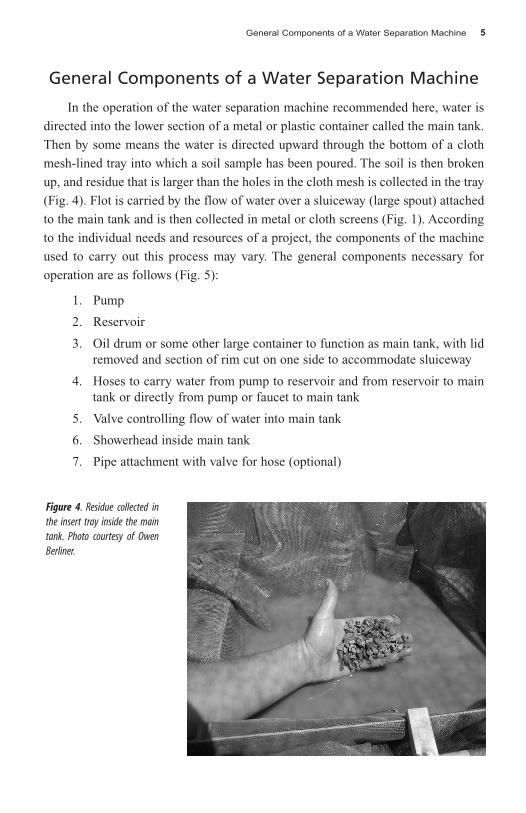
Figure 4. Residue collected in the insert tray inside the main tank. Photo courtesy of Owen Berliner. . . . . . . . . . . . . . . . . . . . . . . . . . . . . . . . . . . . . . 5
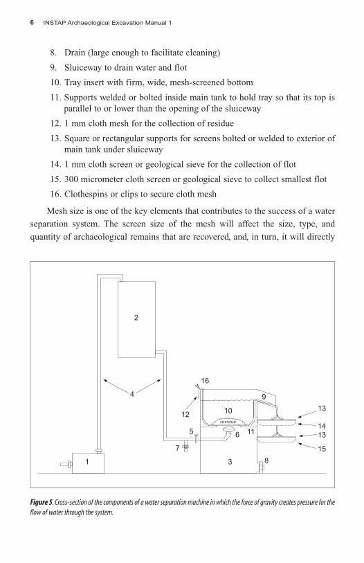
Figure 5. Cross-section of the components of a water separation machine in which the force of gravity creates pressure for the flow of water through the system. . . . . . . . . . . . . . . . . . . . . . . . . . . . . . . . . . . . . . . . . . . . . . . . . 6
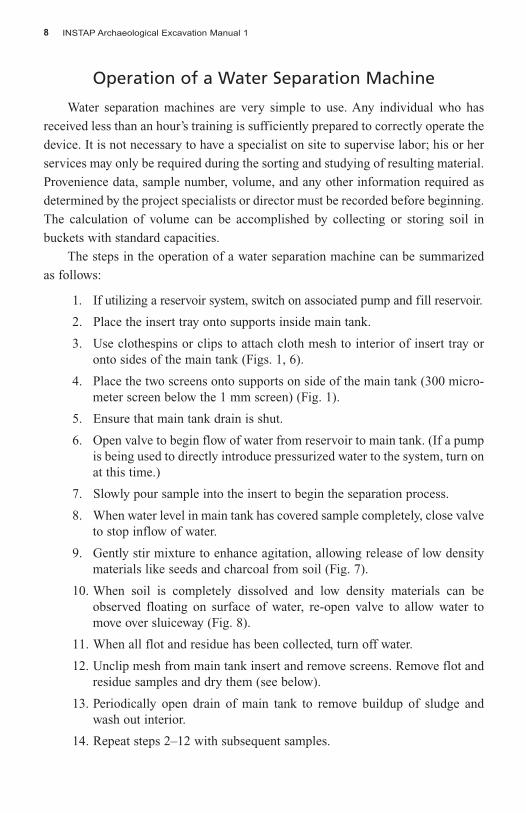
Figure 6. Student clipping cloth mesh to the interior of the main tank. . . . . . . . . . . .9
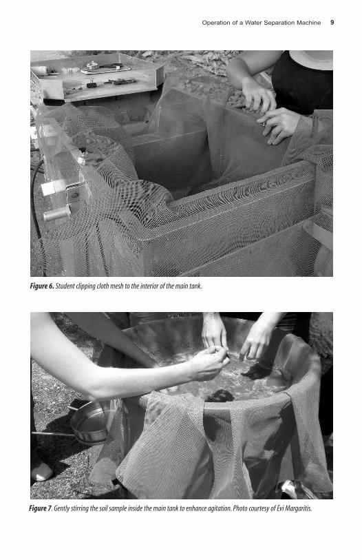
Figure 7. Gently stirring the soil sample inside the main tank to enhance agitation. Photo courtesy of Evi Margaritis. . . . . . . . . . . . . . . . . . . . . . . . . . . . . . 9
Figure 8. Photograph showing the flow of water from the main tank over the sluiceway and into the flot mesh. . . . . . . . . . . . . . . . . . . . . . . . . . . . . . . . . .10
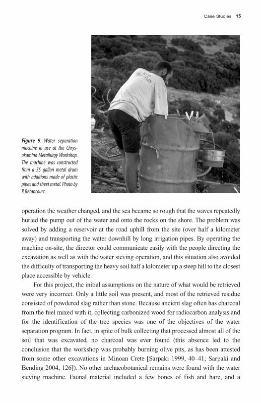
Figure 9. Water separation machine in use at the Chrysokamino Metallurgy Workshop. The machine was constructed from a 55 gallon metal drum with additions made of plastic pipes and sheet metal. Photo by P. Betancourt. . . . . . . . . . . . . . . . . . . . . . . . . . . . . . . . . . . . . . . . . . . . . . . . . . . . . . . . .15
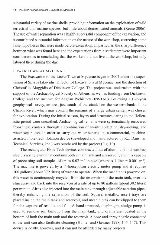
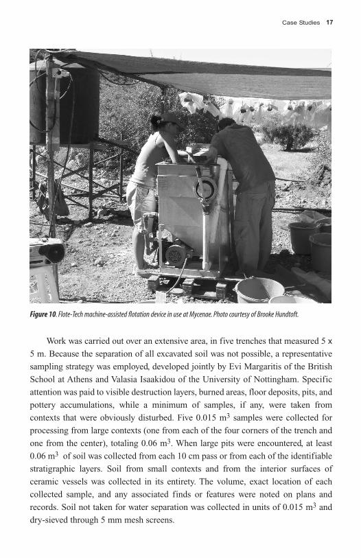
Figure 10. Flote-Tech machine-assisted flotation device in use at Mycenae. Photo courtesy of Brooke Hundtoft. . . . . . . . . . . . . . . . . . . . . . . . . . . . . . . . . . 17
Introduction 1
Introduction
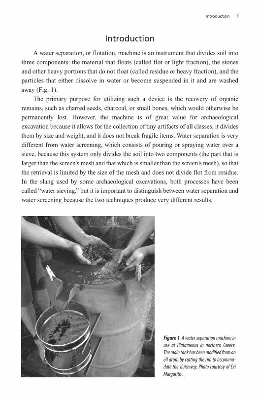
A water separation, or flotation, machine is an instrument that divides soil into
three components: the material that floats (called flot or light fraction), the stones
and other heavy portions that do not float (called residue or heavy fraction), and the
particles that either dissolve in water or become suspended in it and are washed
away (Fig. 1).
The primary purpose for utilizing such a device is the recovery of organic
remains, such as charred seeds, charcoal, or small bones, which would otherwise be
permanently lost. However, the machine is of great value for archaeological
excavation because it allows for the collection of tiny artifacts of all classes, it divides
them by size and weight, and it does not break fragile items. Water separation is very
different from water screening, which consists of pouring or spraying water over a
sieve, because this system only divides the soil into two components (the part that is
larger than the screen’s mesh and that which is smaller than the screen’s mesh), so that
the retrieval is limited by the size of the mesh and does not divide flot from residue.
In the slang used by some archaeological excavations, both processes have been
called “water sieving,” but it is important to distinguish between water separation and
water screening because the two techniques produce very different results.
Figure 1. A water separation machine inuse at Platamonas in northern Greece.The main tank has been modified from anoil drum by cutting the rim to accommo-date the sluiceway. Photo courtesy of EviMargaritis.
INSTAP Archaeological Excavation Manual 12
Use of a water separation machine requires four stages in the recovery of
archaeological material:
1. Retrieval of archaeological sediments
2. Operation of the water separation machine
3. Sorting of materials
4. Study of materials
Goals for Using Water Separation Machines
One of the primary goals of the archaeologist is the collection of material
evidence to aid in the understanding of the past, and the methods by which these
remains are collected during excavation will influence these interpretations. If recov -
ery techniques carried out in the field are biased toward larger, more visible remains,
conclusions that are based solely on such materials will be incomplete and inaccurate.
Additional contextual information, therefore, must be obtained from the collection
and analysis of smaller, less noticeable items. Water separation allows for the retrieval
of such materials.
Small archaeological remains that can be retrieved through water separation
include the following:
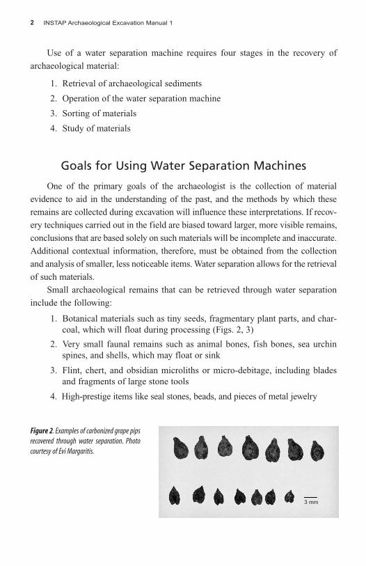
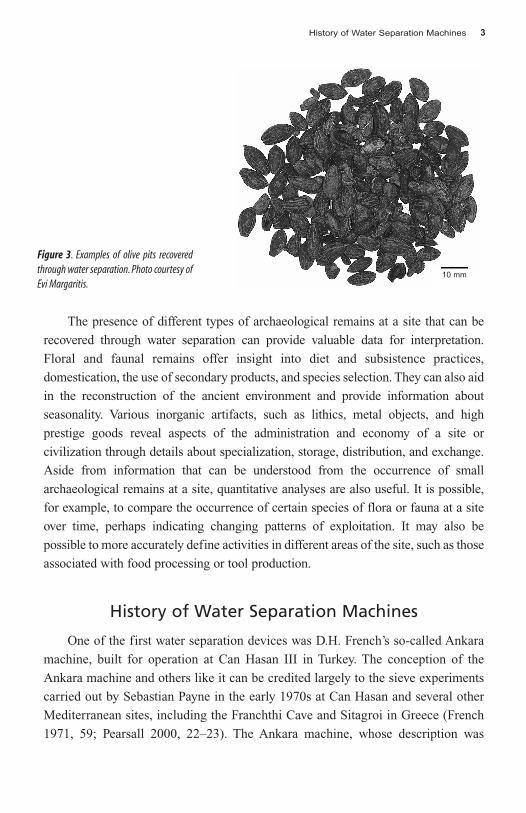
1. Botanical materials such as tiny seeds, fragmentary plant parts, and char-coal, which will float during processing (Figs. 2, 3)
2. Very small faunal remains such as animal bones, fish bones, sea urchinspines, and shells, which may float or sink
3. Flint, chert, and obsidian microliths or micro-debitage, including bladesand fragments of large stone tools
4. High-prestige items like seal stones, beads, and pieces of metal jewelry
Figure 2. Examples of carbonized grape pipsrecovered through water separation. Photocourtesy of Evi Margaritis.
3 mm
History of Water Separation Machines 3
The presence of different types of archaeological remains at a site that can be
recovered through water separation can provide valuable data for interpretation.
Floral and faunal remains offer insight into diet and subsistence practices,
domestication, the use of secondary products, and species selection. They can also aid
in the reconstruction of the ancient environment and provide information about
seasonality. Various inorganic artifacts, such as lithics, metal objects, and high
prestige goods reveal aspects of the administration and economy of a site or
civilization through details about specialization, storage, distribution, and exchange.
Aside from information that can be understood from the occurrence of small
archaeological remains at a site, quantitative analyses are also useful. It is possible,
for example, to compare the occurrence of certain species of flora or fauna at a site
over time, perhaps indicating changing patterns of exploitation. It may also be
possible to more accurately define activities in different areas of the site, such as those
associated with food processing or tool production.
History of Water Separation Machines
One of the first water separation devices was D.H. French’s so-called Ankara
machine, built for operation at Can Hasan III in Turkey. The conception of the
Ankara machine and others like it can be credited largely to the sieve experiments
carried out by Sebastian Payne in the early 1970s at Can Hasan and several other
Mediterranean sites, including the Franchthi Cave and Sitagroi in Greece (French
1971, 59; Pearsall 2000, 22–23). The Ankara machine, whose description was
Figure 3. Examples of olive pits recoveredthrough water separation. Photo courtesy ofEvi Margaritis.
10 mm
INSTAP Archaeological Excavation Manual 14
published by French in 1971, was designed to use two main components—a main
box into which soil samples were poured and a flot box used to collect delicate
remains—through which water continuously flowed from a reservoir situated at a
higher elevation. The pressure of the falling water served to break up the matrix of
the soil, float and separate buoyant materials, and clean nonbuoyant remains
(French 1971, 59, 61; Pearsall 2000, 22–24).
The development of later machine-assisted water separation devices has
largely been based on the original design of the Ankara machine, with various
modifications and improvements made to suit different projects. For example, the
Franchthi Cave device, developed by Thomas Jacobson, was very similar in
character, although it used saline water to process soil (Diamant 1979, 210–212;
Pearsall 2000, 24–25). W.F. Limp proposed an influential modification in 1974 in
which the flow of water was oriented directly at the bottom of the screen of the
main box, thereby increasing the agitation of the soil (Limp 1974, 339). David
Williams similarly designed a machine for use at the Siraf site in southern Iran that
used a 50 gallon drum as the main box (Pearsall 2000, 25; Williams 1973,
288–289).
For each of these water separation devices, water pressure was produced by the
force of gravity created through the downward flow of water from the reservoir to
the main box. However, the machine from the Shellmound Archaeological Project
(SMAP), designed by Bill Robertson for use in North America, did not require such
a scheme. The device, also a variation of the Ankara machine, resembled the Siraf
design and used a gas or electric pump to direct pressurized water into the main
tank (Pearsall 2000, 27). Therefore, whereas the Ankara machine and its later
departures were permanent installations, the SMAP device could be used almost
anywhere, utilizing any source of water (Watson 1976, 82). The SMAP machine
also did not employ the frame and removable mesh technique commonly used in
European systems and had no flot box; fragile remains were caught directly in a
bucket or geological sieve located underneath the sluiceway (Pearsall 2000, 27;
Watson 1976, 82).
The particular alterations introduced in these variations of the Ankara machine
would be widely and successfully adopted by other excavations all over the world.
Several types of machines exist at present, with many distinct elements that are
interchangeable, modifiable, and variable depending on individual desires, needs,
and available resources. As long as one adheres to the basic principles of water
separation, it is possible to construct a device suited to any archaeological project.
General Components of a Water Separation Machine 5
General Components of a Water Separation Machine
In the operation of the water separation machine recommended here, water is
directed into the lower section of a metal or plastic container called the main tank.
Then by some means the water is directed upward through the bottom of a cloth
mesh-lined tray into which a soil sample has been poured. The soil is then broken
up, and residue that is larger than the holes in the cloth mesh is collected in the tray
(Fig. 4). Flot is carried by the flow of water over a sluiceway (large spout) attached
to the main tank and is then collected in metal or cloth screens (Fig. 1). According
to the individual needs and resources of a project, the components of the machine
used to carry out this process may vary. The general components necessary for
operation are as follows (Fig. 5):
1. Pump
2. Reservoir
3. Oil drum or some other large container to function as main tank, with lidremoved and section of rim cut on one side to accommodate sluiceway
4. Hoses to carry water from pump to reservoir and from reservoir to maintank or directly from pump or faucet to main tank
5. Valve controlling flow of water into main tank
6. Showerhead inside main tank
7. Pipe attachment with valve for hose (optional)
Figure 4. Residue collected inthe insert tray inside the maintank. Photo courtesy of OwenBerliner.
INSTAP Archaeological Excavation Manual 16
8. Drain (large enough to facilitate cleaning)
9. Sluiceway to drain water and flot
10. Tray insert with firm, wide, mesh-screened bottom
11. Supports welded or bolted inside main tank to hold tray so that its top isparallel to or lower than the opening of the sluiceway
12. 1 mm cloth mesh for the collection of residue
13. Square or rectangular supports for screens bolted or welded to exterior ofmain tank under sluiceway
14. 1 mm cloth screen or geological sieve for the collection of flot
15. 300 micrometer cloth screen or geological sieve to collect smallest flot
16. Clothespins or clips to secure cloth mesh
Mesh size is one of the key elements that contributes to the success of a water
separation system. The screen size of the mesh will affect the size, type, and
quantity of archaeological remains that are recovered, and, in turn, it will directly
Figure 5. Cross-section of the components of a water separation machine in which the force of gravity creates pressure for theflow of water through the system.
2
4
1
12
16
10
11
13
14
13
15
65
8
9
7
3
residue
General Components of a Water Separation Machine 7
influence interpretation. Although recommendations have been made above, the
size of the mesh can vary from project to project. It is important that the mesh size
is small enough to capture essential materials, but not so small as to clog the mesh
with sediment, thereby causing overflow. The location of the inflow pipe on the
main tank is also crucial. Enough space must be available above the pipe to
accommodate the insert tray and ensure that samples can be processed efficiently.
The size of the space left below the inflow pipe will also determine how many
samples can be processed before the unit must be cleaned.
Sufficient water pressure must be created to allow for the efficient processing
of soil samples in the main tank. Some devices utilize a system in which a reservoir
tank is filled with water and placed at an elevation higher than that of the main tank.
A hose is then connected from the reservoir to the main tank, and when the valve
of the main tank is opened, water flows down the hose into the main tank. This type
of system can be advantageous both because it does not require a constant supply
of water and because the pump does not need to be continuously operated. The
water inflow can also be connected directly to a pump, bypassing the need for a
reservoir. These systems draw and filter water from readily available sources such
as rivers, lakes, or the sea. The inflow also can be connected to a water tap, provided
that it is able to generate an adequate level of pressure.
If ample water supply is limited, the separation device can be modified to
recycle the liquid. Water can be collected in a settling basin, tank, or tub of some
kind after the residue and flot have been completely removed. After silt has settled,
the water can be siphoned off, directed to the water inflow, and used again. The
intake hose in this case must be filtered with fine mesh to prevent the contamination
of subsequent samples. Similarly, if fresh water is scarce, it is possible to use salt
water at little or no risk to the archaeological materials. In fact, it has been sug -
gested that the buoyancy of some remains is increased when salt water is util ized,
thereby increasing the efficiency of recovery (Diamant 1979, 213; Lange and Carty
1975, 122).
When constructing a water separation machine, all hoses and adaptors should be
the same diameter. This way the system may be more economical and efficient, as
stress on the pump will be minimized and individual parts will be easier to replace.
However, the drainage system of the main tank should be wider to allow rapid
cleaning between samples (Diamant 1979, 211; Pearsall 2000, 50). The machine also
should be leveled before operation to ensure the even flow of water. The operator
should make certain that the device functions correctly and is free of leaks. He or she
should properly maintain and frequently check all of the equipment.
INSTAP Archaeological Excavation Manual 18
Operation of a Water Separation Machine
Water separation machines are very simple to use. Any individual who has
received less than an hour’s training is sufficiently prepared to correctly operate the
device. It is not necessary to have a specialist on site to supervise labor; his or her
services may only be required during the sorting and studying of resulting material.
Provenience data, sample number, volume, and any other information required as
determined by the project specialists or director must be recorded before beginning.
The calculation of volume can be accomplished by collecting or storing soil in
buckets with standard capacities.
The steps in the operation of a water separation machine can be summarized
as follows:
1. If utilizing a reservoir system, switch on associated pump and fill reservoir.
2. Place the insert tray onto supports inside main tank.
3. Use clothespins or clips to attach cloth mesh to interior of insert tray oronto sides of the main tank (Figs. 1, 6).
4. Place the two screens onto supports on side of the main tank (300 micro -meter screen below the 1 mm screen) (Fig. 1).
5. Ensure that main tank drain is shut.
6. Open valve to begin flow of water from reservoir to main tank. (If a pumpis being used to directly introduce pressurized water to the system, turn onat this time.)
7. Slowly pour sample into the insert to begin the separation process.
8. When water level in main tank has covered sample completely, close valveto stop inflow of water.
9. Gently stir mixture to enhance agitation, allowing release of low densitymaterials like seeds and charcoal from soil (Fig. 7).
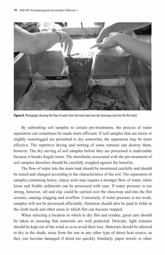
10. When soil is completely dissolved and low density materials can beobserved floating on surface of water, re-open valve to allow water tomove over sluiceway (Fig. 8).
11. When all flot and residue has been collected, turn off water.
12. Unclip mesh from main tank insert and remove screens. Remove flot andresidue samples and dry them (see below).
13. Periodically open drain of main tank to remove buildup of sludge andwash out interior.
14. Repeat steps 2–12 with subsequent samples.
Operation of a Water Separation Machine 9
Figure 7. Gently stirring the soil sample inside the main tank to enhance agitation. Photo courtesy of Evi Margaritis.
Figure 6. Student clipping cloth mesh to the interior of the main tank.
INSTAP Archaeological Excavation Manual 110
By submitting soil samples to certain pre-treatments, the process of water
separation can sometimes be made more efficient. If soil samples that are moist or
slightly waterlogged are permitted to dry somewhat, the separation may be more
effective. The repetitive drying and wetting of some remains can destroy them,
however. The dry sieving of soil samples before they are processed is inadvisable
because it breaks fragile items. The drawbacks associated with the pre-treatment of
soil samples therefore should be carefully weighed against the benefits.
The flow of water into the main tank should be monitored carefully and should
be tested and changed according to the characteristics of the soil. The separation of
samples containing heavy, clayey soils may require a stronger flow of water, while
loose and friable sediments can be processed with ease. If water pressure is too
strong, however, silt and clay could be carried over the sluiceway and into the flot
screens, causing clogging and overflow. Conversely, if water pressure is too weak,
samples will not be processed efficiently. Attention should also be paid to folds in
the cloth mesh and other areas in which flot can become trapped.
When selecting a location in which to dry flot and residue, great care should
be taken in ensuring that materials are well protected. Delicate, light remains
should be kept out of the wind so as to avoid their loss. Materials should be allowed
to dry in the shade, away from the sun or any other type of direct heat source, as
they can become damaged if dried too quickly. Similarly, paper towels or other
Figure 8. Photograph showing the flow of water from the main tank over the sluiceway and into the flot mesh.
Retrieval of Soil 11
absorbent materials can rapidly leech water from fragile materials, causing them to
dry too rapidly. Flot and residue samples can be laid on clean sheets of plastic to
dry, or placed onto a drying table with a fine mesh bottom. In systems that utilize
removable mesh for the capture of flot, the flot can be bundled inside of the cloth
mesh and hung to dry. However, because the cloth mesh cannot be reused until the
flot is entirely dry, the project will need to have an ample supply of it to use for the
processing of other samples.
Processing samples in the field, as opposed to a location away from the
archaeological site, has several advantages. The problem of organizing transportation
for a large amount of heavy soil samples is eliminated when they are processed on-
site. The results also can be immediately reported back to excavators working in the
field, thus enhancing the accuracy of on-site interpretations and allowing the
immediate application of necessary modifications to the sampling system. If lack of
water or other impediments make it impossible to operate a water separation machine
on site, samples should nonetheless be processed during the period of excavation to
similarly allow prompt feedback.
Retrieval of Soil
The objectives of the soil sampling strategy for water separation will vary
between excavations, and they should be developed under the guidance of project
specialists in order to answer specific archaeological questions. The availability of
such resources as funding, labor, and time should also be taken into account. The
collection system utilized ultimately will determine the kind, quantity, and quality
of interpretative data that is obtained, and it should be carefully planned. Two
methods exist for collection of soil for water separation: bulk collection of all
excavated soil and representative sampling.
BULK COLLECTION
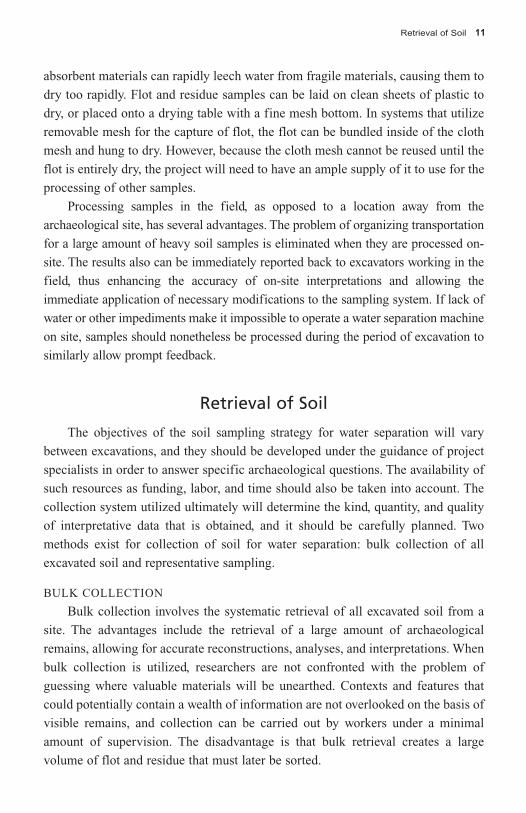
Bulk collection involves the systematic retrieval of all excavated soil from a
site. The advantages include the retrieval of a large amount of archaeological
remains, allowing for accurate reconstructions, analyses, and interpretations. When
bulk collection is utilized, researchers are not confronted with the problem of
guessing where valuable materials will be unearthed. Contexts and features that
could potentially contain a wealth of information are not overlooked on the basis of
visible remains, and collection can be carried out by workers under a minimal
amount of supervision. The disadvantage is that bulk retrieval creates a large
volume of flot and residue that must later be sorted.
INSTAP Archaeological Excavation Manual 112
REPRESENTATIVE SAMPLING
If the project is unable to process all excavated soil, representative samples of
the fill from contexts and features can be collected. Three methods are often used
to collect such samples (Lennstrom and Hastorf 1992, 206; Pearsall 2000, 69, 71):
1. Composite or scatter sampling, which combines small “pinches” of soiltaken from many locations throughout a context in a single bag
2. Point sampling, the collection of soil from a series of single, well-definedlocations
3. Column sampling, utilized when soil is excavated from a series of hori-zontal or successive layers, such as consecutive floor deposits
More than one system is often used on a single project, and many variations of
each exist. Point sampling, for example, can sometimes involve taking five samples
per level, one from each corner of the trench and one from the center. During
representative sampling, the strategy usually focuses on well-defined features and
contexts that are most likely to contain remains. Soil from features such as hearths,
burials, pits, floors, and the insides of ceramic vessels should be bulk collected if
possible. Additionally, soil samples are taken from areas where archaeological
remains are not expected to occur, in order to provide meaningful comparative data.
Sorting and Study of Remains
SORTING OF REMAINS
Following the processing of soil samples, archaeological materials present in
the dried flot and residue are sorted and identified. During sorting, recovered
remains are classified primarily based on size and appearance. Students and other
unskilled individuals can be employed to sort and initially identify residue samples
because a basic familiarity with commonly represented materials is sufficient. New
workers should be shown examples of the items that they will encounter, and the
instruction of a specialist, material identification manuals, taxonomy textbooks,
and comparative collections can be helpful in this respect. A specialist, such as an
archaeobotanist, usually sorts through flot samples with the aid of a microscope.
Materials must be handled with care during sorting, and small hand tools such as
fine paintbrushes and tweezers can be utilized.
STUDY OF RECOVERED REMAINS
After recovered remains have been sorted into their respective categories, a
specialist analyzes the material, usually in a laboratory. An archaeobotanist,
Contamination 13
archaeozoologist, lithics expert, or other specialists can be employed by a project
depending on the types of remains recovered. The first task of a specialist is to
identify and quantify remains based on morphological features. Initially, materials
can be observed under light microscopy, and some analyses can be carried out with
the aid of video and computer equipment. If items are extremely fragmentary or
diminutive, more advanced techniques (such as scanning electron microscopy) can
aid in their identification. Also, some organic materials can be cut into thin
sections, embedded in slides, and analyzed through transmitted light microscopy or
transmission electron microscopy (Pearsall 2000, 170, 175, 177–178).
Recovered organic materials can also be studied on a molecular level. Molecules
and compounds, such as lipids and proteins, can be extracted from ambiguous remains
to allow classification. Botanical remains can be further identified and studied through
the analysis of starch grains. It may also be possible to identify starch grain residues
from the tiny crevices and cracks of small stone tools, thus providing information
about how they were used. Stone tools can also be studied through micro-wear
analysis, and it may be possible to reconstruct larger stone artifacts from fragments and
source raw materials. DNA and other chemical analyses can often be carried out on
certain botanical and faunal remains. Bones can be tested for traces of carbon and
nitrogen isotopes, and metal objects can similarly be subjected to lead isotope and
trace-element analysis (Pearsall 2000, 178-179, 182–184, 187). After the specialist has
identified the presence of different types of archaeological remains at a site, resulting
qualitative and quantitative data may be used for interpretation.
Contamination
Materials can become contaminated at every stage of collection. Soil samples can
become contaminated before retrieval by modern seeds or other materials that fall into
the topsoil through dry cracks and root holes or as the result of plowing and burrowing.
Contamination can also occur if samples are recovered, stored, or transported without
care. Some types of ancient remains, such as seeds and other plant parts, are unlikely
to survive unless they are preserved by charring or desiccation. It may be relatively
simple, therefore, to distinguish modern contaminants from ancient material. Some
waterlogged remains, however, may appear to be modern in origin, so the conditions
of the site must be carefully considered before distinctions are made (Keepax 1997,
221, 224–227).
Cross-contamination of samples also can take place inside the machine during
processing. If the water separation machine is constructed, operated, and maintained
INSTAP Archaeological Excavation Manual 114
correctly, there is a very low risk of contamination. The machine and all of its
associated parts, however, should be cleaned between each sample to ensure that
cross-contamination does not occur. It is especially important to be certain that flot
from a previous sample has not become trapped anywhere in the main tank where it
could be mixed with the sample currently in process. Both the residue cloth mesh and
the flot screens should be gently washed of any remains before they are reused to
process subsequent samples. If samples are dried on flat surfaces they must be
completely removed before other samples are laid in their place.
Case Studies
CHRYSOKAMINO METALLURGY WORKSHOP
The Cretan copper smelting workshop at Chrysokamino was excavated in 1996
and 1997 under the direction of Philip P. Betancourt. The site, which was situated at
the top of a cliff overlooking the Aegean Sea, was covered with a pile of slag
containing pottery from Final Neolithic to Early Minoan III. The excavation uncov -
ered a small hut and extensive evidence for the copper smelting operation. In addition
to the slag, finds included chimney fragments, pieces of ore, a tuyere, part of the wall
of a furnace, and pot bellows (Betancourt 2006).
The program to retrieve materials with a water separation machine was a
collaborative effort with Glynis Jones at the University of Sheffield and David S.
Reese at the Peabody Museum, Yale University. Students from Sheffield operated
the machine and performed preliminary sorting during the excavation season. The
sorted flot was sent to Sheffield for detailed examination and study, and the residue
was sorted in Crete by various members of the staff so that faunal material could
be studied by Reese at the INSTAP Study Center for East Crete in Pacheia Ammos.
Mark Hudson operated the machine in 1996, and Ann Schofield performed this
task in 1997. The program successfully retrieved a variety of materials, and it
contributed considerable information for the interpretation of the site that would
not have been available otherwise.
The excavation used a machine that was constructed from a 55 gallon metal drum
with additions made of plastic pipes and sheet metal (Fig. 9). The two geological sieves
for retrieving the flot were brought to the site from Britain, but the cloth mesh for the
top and all other components were purchased locally in Crete. Because the site was
near the coast, initially the water was supplied from the sea by means of an irrigation
pump and plastic irrigation pipe, with the flow going directly to the machine with no
intermediate reservoir. This system worked satisfactorily, but after a few days of
Case Studies 15
Figure 9. Water sep a r ationmachine in use at the Chrys -okamino Metallurgy Wor k shop.The machine was constructedfrom a 55 gallon metal drumwith additions made of plasticpipes and sheet metal. Photo by P. Betancourt.
operation the weather changed, and the sea became so rough that the waves repeatedly
hurled the pump out of the water and onto the rocks on the shore. The problem was
solved by adding a reservoir at the road uphill from the site (over half a kilometer
away) and transporting the water downhill by long irrigation pipes. By operating the
machine on-site, the director could communicate easily with the people directing the
excavation as well as with the water sieving operation, and this situation also avoided
the difficulty of transporting the heavy soil half a kilometer up a steep hill to the closest
place accessible by vehicle.
For this project, the initial assumptions on the nature of what would be retrieved
were very incorrect. Only a little soil was present, and most of the retrieved residue
consisted of powdered slag rather than stone. Because ancient slag often has charcoal
from the fuel mixed with it, collecting carbonized wood for radiocarbon analysis and
for the identification of the tree species was one of the objectives of the water
separation program. In fact, in spite of bulk collecting that processed almost all of the
soil that was excavated, no charcoal was ever found (this absence led to the
conclusion that the workshop was probably burning olive pits, as has been attested
from some other excavations in Minoan Crete [Sarpaki 1999, 40–41; Sarpaki and
Bending 2004, 126]). No other archaeobotanical remains were found with the water
sieving machine. Faunal material included a few bones of fish and hare, and a
INSTAP Archaeological Excavation Manual 116
substantial variety of marine shells, providing information on the exploitation of wild
terrestrial and marine species, but little about domesticated animals (Reese 2006).
The use of water separation was a highly successful component of the excavation, and
it contributed substantial information on the nature of the workshop, correcting some
false hypotheses that were made before excavation. In particular, the sharp difference
between what was found here and the expectations from a settlement were important
considerations in concluding that the workers did not live at the workshop, but only
labored there during the day.
LOWER TOWN AT MYCENAE
The Excavation of the Lower Town at Mycenae began in 2007 under the super -
vision of Spyros Iakovidis, Director of Excavations at Mycenae, and the direction of
Christofilis Maggidis of Dickinson College. The project was undertaken with the
support of the Archaeological Society of Athens, as well as funding from Dickinson
College and the Institute for Aegean Prehistory (INSTAP). Following a five-year
geophysical survey, an area just south of the citadel on the western bank of the
Chavos River, which may contain the remains of a large urban center, was chosen
for exploration. During the initial season, layers and structures dating to the Hellen -
istic period were unearthed. Archaeological remains were systematically re covered
from these contexts through a combination of in-situ collection, dry-sieving, and
water separation. In order to carry out water separation, a commercial, machine-
assisted, Flote-Tech flotation device (developed and manufactured by R.J. Dausman
Technical Services, Inc.) was purchased by the project (Fig. 10).
The rectangular Flote-Tech device, constructed out of aluminum and stainless
steel, is a single unit that contains both a main tank and a reservoir, and it is capable
of processing soil samples of up to 0.02 m3 in size (whereas 1 liter = 0.001 m3).
The machine is powered by a ¾-horsepower electric motor pump and it requires
100 gallons (about 379 liters) of water to operate. When the machine is powered on,
this water is continuously recycled from the reservoir into the main tank, over the
sluiceway, and back into the reservoir at a rate of up to 80 gallons (about 302 liters)
per minute. Air is also injected into the main tank through adjustable aeration pipes,
thereby enhancing the separation of the soil. Square, metallic, insert trays are
placed inside the main tank and reservoir, and mesh cloths can be clipped to them
for the capture of residue and flot. A hand-operated, diaphragm, sludge pump is
used to remove soil buildup from the main tank, and drains are located at the
bottom of both the main tank and the reservoir. A hose and spray nozzle connected
to the unit can also facilitate cleaning (Hunter and Gassner 1998, 145–147). This
device is costly, however, and it can not be afforded by many projects.
Case Studies 17
Work was carried out over an extensive area, in five trenches that measured 5 x
5 m. Because the separation of all excavated soil was not possible, a representative
sampling strategy was employed, developed jointly by Evi Margaritis of the British
School at Athens and Valasia Isaakidou of the University of Nottingham. Specific
attention was paid to visible destruction layers, burned areas, floor deposits, pits, and
pottery accumulations, while a minimum of samples, if any, were taken from
contexts that were obviously disturbed. Five 0.015 m3 samples were collected for
processing from large contexts (one from each of the four corners of the trench and
one from the center), totaling 0.06 m3. When large pits were encountered, at least
0.06 m3 of soil was collected from each 10 cm pass or from each of the identifiable
stratigraphic layers. Soil from small contexts and from the interior surfaces of
ceramic vessels was collected in its entirety. The volume, exact location of each
collected sample, and any associated finds or features were noted on plans and
records. Soil not taken for water separation was collected in units of 0.015 m3 and
dry-sieved through 5 mm mesh screens.
Figure 10. Flote-Tech machine-assisted flotation device in use at Mycenae. Photo courtesy of Brooke Hundtoft.
INSTAP Archaeological Excavation Manual 118
During processing, 1 mm mesh nylon and polyester screen fabric was used for
the capture of residue, while 0.25 mm mesh fabric was used for the collection of
flot. Approximately 100 separate soil samples were processed and sorted
throughout the course of the four week season. One student could be employed to
operate the machine, but processing was generally faster when two or three were
involved. From the preparation of the machine prior to the addition of the sample
to the time that it took to prepare them for drying, each sample took 10–20 minutes
to process. Loose soils generally took less time to process than those of a dense,
clayey nature. The machine was usually cleaned out after every sample, taking 5–10
minutes. At a rate of roughly three samples per hour, a total of 21 samples could
potentially be processed each day. On most days, however, the machine was not
continuously in operation, either due to a lack of samples or because students
needed to be employed for sorting.
Following processing, recovered residue samples were unclipped from the tray
in the main tank and dried in the shade on screens or plastic sheets. In general, it
took one day for residue samples to dry before they could be sorted by students.
One student could sort a large residue sample in 1–2 hours, while smaller samples
took anywhere from 30 minutes to 1 hour. After processing, flot samples were sim -
ilarly unclipped from the tray in the reservoir, bundled, and hung in the shade to dry.
Flot samples took anywhere from one half of a day to one full day to dry. Following
this, flot samples were bagged and sent to the museum to be processed by the
archaeobotanist.
The samples from the 2007 season primarily yielded botanical remains, specif -
ically grape pips, olive stones, and cereal grains. The deposition of these materials was
attributed to secondary activities such as spillage or accidents during food preparation.
Some tiny animal bones and minuscule pieces of worked flint were also recovered
from many samples.
Acknowledgments
Many thanks are extended to the following persons for photographs and infor -
mation: Evi Margaritis, Christofilis Maggidis, Tanya McCullough, Owen Berliner, and
Brooke Hundtoft. Uncredited photos are by the author.
Bibliography
Abbreviations follow the conventions suggested in the American Journal of Archaeology111.1 (2007), pp. 14–34.
Betancourt, P.P. 2006. The Chrysokamino Metallurgy Workshop and Its Territory (HesperiaSuppl. 36), Princeton.
Diamant, S. 1979. “A Short History of Archaeological Sieving at Franchthi Cave, Greece,”JFA 6, pp. 203–217.
French, D.H. 1971. “An Experiment in Water-Sieving,” AnatSt 21, pp. 59–64.
Hunter, A.A., and B.R. Gassner. 1998. “Evaluation of the Flote-Tech Machine-AssistedFlotation System,” AmerAnt 63, pp. 143–156.
Keepax, C. 1977. “Contamination of Archaeological Deposits by Seeds of Modern Originwith Particular Reference to the Use of Flotation Machines,” JAS 4, pp. 221–229.
Lange, F.W., and F.M. Carty. 1975. “Salt Water Application of the Flotation Technique,” JFA2, pp. 119–123.
Lennstrom, H.A., and C.A. Hastorf. 1995. “Interpretation in Context: Sampling and Analysisin Paleoethnobotany,” AmerAnt 60, pp. 701–721.
Limp, W.F. 1974. “Water Separation and the Flotation Process,” JFA 1, pp. 337–342.
Pearsall, D.M. 2000. Paleoethnobotany: A Handbook of Procedures, 2nd edition, San Diego.
Reese, D.S. 2006. “Faunal Remains,” in Betancourt, 2006, pp. 149–152.
Renfrew, C., and P. Bahn. 2007. Archaeology Essentials: Theories, Methods, and Practice,London.
Sarpaki, A. 1999. “The Archaeobotanical Study of Tzambakas House, Rethymnon, Crete,”in Minoans and Mycenaeans: Flavours of Their Time, Y. Tzedakis and H. Martlew, eds.,Athens, pp. 40–41.
INSTAP Archaeological Excavation Manual 120
Sarpaki, A., and J. Bending. 2004. “Archaeobotanical Assemblages,” in Mochlos IC: PeriodIII. Neopalatial Settlement on the Coast: The Artisans’ Quarter and the Farmhouse atChalinomouri. The Small Finds (Prehistory Monographs 9), J.S. Soles and C. Davaras,eds., Philadelphia, pp. 126–131.
Stahl, P.W. 1982. “On Small Mammal Remains in Archaeological Context,” AmerAnt 47, pp.822–829.
Watson, P.J. 1976. “In Pursuit of Prehistoric Subsistence: A Comparative Account of SomeContemporary Flotation Techniques,” Midcontinental Journal of Archaeology 1, pp.77–100.
Williams, D. 1973. “Flotation at Siraf,” Antiquity 47, pp. 288–292.
Wright, P.J. 2005. “Flotation Samples and Some Paleoethnobotanical Implications,” JAS 32,pp. 19–26.
RECOMMENDATIONS FOR FURTHER READING:
Davis, E.M., and A.B. Wesolowsky. 1975. “The Izum: A Simple Water Separation Device,”JFA 2, pp. 271–273.
Dye, D.H., and K.H. Moore. 1978. “Recovery Systems for Subsistence Data: WaterScreening and Water Flotation,” Tennessee Anthropologist III, pp. 59–69.
Hastorf, C. 1999. “Recent Research in Paleoethnobotany,” Journal of ArchaeologicalResearch 7, pp. 55–103.
Higgs, E.S., ed. 1972. Papers in Economic Prehistory: Studies by Members and Associatesof the British Academy Major Research Project in the Early History of Agriculture,Cambridge.
James, S.R. 1997. “Methodological Issues Concerning Screen Size Recovery Rates andTheir Effects on Archaeofaunal Interpretations,” JAS 24, pp. 385–397.
Struever, S. 1968. “Flotation Techniques for the Recovery of Small-Scale ArchaeologicalRemains,” AmerAnt 33, pp. 353–362.
Wagner, G.E 1982. “Testing Flotation Recovery Rates,” AmerAnt 47, pp. 127–132.
———. 1988. “Comparability among Recovery Techniques,” in Current Paleoethnobotany:Analytical Methods and Cultural Interpretations of Archaeological Plant Remains, C.A.Hastorf and V.S. Popper, eds., Chicago, pp. 17–35


