
Research ArticleCircularly Polarized Triband Printed Quasi-Yagi Antenna forMillimeter-Wave Applications
Dalia M. Elsheakh1 and Magdy F. Iskander2
1Microstrip Department, Electronics Research Institute, Cairo 21622, Egypt2Hawaii Center for Advanced Communications (HCAC), Honolulu, HI 96822, USA
Correspondence should be addressed to Dalia M. Elsheakh; [email protected]
Received 30 October 2014; Revised 21 January 2015; Accepted 25 January 2015
Academic Editor: Atsushi Mase
Copyright © 2015 D. M. Elsheakh and M. F. Iskander. This is an open access article distributed under the Creative CommonsAttribution License, which permits unrestricted use, distribution, and reproduction in any medium, provided the original work isproperly cited.
This paper describes the design and development of a triband with circularly polarized quasi-Yagi antenna for ka-band and shortrange wireless communications applications. The proposed antenna consists of an integrated balun-fed printed dipole, parasiticfolded dipole and a short strip, and amodified ground plane.The antenna structure, together with the parasitic elements, is designedto achieve circular polarization and triband operating at resonant frequencies of 13.5 GHz, 30GHz, and 60GHz. Antenna designwas first simulated using HFSS ver.14, and the obtained results were compared with experimental measurements on a prototypedeveloped on a single printed circuit board. Achieved characteristics include −10 dB impedance bandwidth at the desired bands,circular polarization axial ratio 𝐴𝑅 < 3 dB, front to back ratio of 6 dB, gain value of about 4 dBi, and average radiation efficiency of60%. The paper includes comparison between simulation and experimental results.
1. Introduction
Recently printed antennas have been commonly used insensing and various communications and radar systemsapplications due to their low cost, low profile, and simpleintegration with transceiver systems. For example, microstriparrays are highly desired for the broadcast satellite services(BSS) in the frequency band at 13.5 GHz [1]. Moreover,the unlicensed frequency bands in the 30GHz and 60GHzranges are used for increased data rate of more than 1Gb/sin WLAN (wireless local area network IEEE 802.11n) andWPAN (wireless personal area network) short range commu-nication systems [2].
Some examples of printed antenna implementations illus-trate specific and interesting particular solutions and showthat they can be integrated with solid-state devices [3–5]. Ofspecific interest in this paper are those designs that are basedon new shapes of Yagi-antenna implementation. Yagi-typeantennas have several advantages overmany other commonlyused ones in portable communication systems [5–7]. First,the presence of the substrate provides mechanical support
for the antenna and planar transmission line compatibility.Second, the parasitic director element on the top plane simul-taneously directs the antenna propagation towards the end-fire direction and acts as an impedance-matching parasiticelement as well [8].
Development of antennas with circular polarization (CP)radiation patterns is also desirable in satellite communi-cations systems and for portable wireless communicationssystems as they reduce multipath fading effects and provideflexibility in the orientation angles between transmitters andreceivers. However, CP antennas reduce efficiency comparedto linearly polarized antennas [7, 9]. Many CP antennas alsohave complex feeding networks and configurations and henceincrease packaging cost and system sizes [10]. Nonetheless,various integrated CP antenna designs have been proposedfor MM-wave applications and these designs were imple-mented in either multilayer or one-layer solutions [11].
Development of antennas with multiband radiation char-acteristics is yet another desirable and important feature.Various techniques of printed MM-wave antenna for dualband and circular polarization have been reported [12].These
Hindawi Publishing CorporationInternational Journal of Antennas and PropagationVolume 2015, Article ID 329453, 9 pageshttp://dx.doi.org/10.1155/2015/329453

2 International Journal of Antennas and Propagation
LD
Ls Ls1
LR LR1
Sdir
Lg
g
Wg Wf
Wsub
K
D
D
R
S
Air bridge
X
Y
Truncatedground plane
Reflector
Driver
Director
Lsub
Figure 1: The proposed quasi-Yagi antenna configuration.
designs, however, have not been widely used due to severalundesirable features, including narrowband, small axial ratio,and relatively complex structures and heavier weights.
The main objective of this paper is to describe the designof a low cost, simple structure, multiband quasi-Yagi antennawith circular polarization radiation pattern. The rest of thepaper is organized as follows: in Section 2, the design andsimulation of the quasi-Yagi antenna are described. Section 3discusses the experimental measurements and results.Section 4 concludes and summarizes features and char-acteristics of the designed antenna.
2. Antenna Design and Simulation
As mentioned earlier, printed quasi-Yagi antenna is widelyused in communication and radar applications due to itshigh directivity, high radiation efficiency, low profile, andease of fabrication. It has, however, narrow bandwidth, andthis is considered its main disadvantage. Aimed at increasingthe bandwidth of planar printed quasi-Yagi antennas, manydesigns have been reported [8]. In this paper, a hybrid T-dipole and quasi-Yagi antenna have been used to achievebroadband as shown in Figure 1.
In this case, the quasi-Yagi antenna consists of a groundplane that acts as a reflector with width 𝑊𝑔 and length 𝐿𝑔,T-shaped printed dipole with length 𝐿𝑆 as a driven element,and the parasitic strip with length 𝐿𝐷 as a director which isprinted at distance 𝑅 from the driven element of the antenna.Design method is on feeding (balun) structure to improvethe impedance bandwidth [13–15]. Various design shapes indeveloping this antenna, shown in Figures 2(a)–2(c), havebeen studied and obtained. |𝑆11| results for each of thesecases are shown in Figure 2(d). First, the response of thefolded dipole CPW-fed shown in Figure 2(a) was simulatedand |𝑆11| results are shown as blue dashed line in Figure 2(d).
Table 1: Optimized proposed antenna dimensions (mm).
𝐿 sub 𝐿
𝑔𝐿
𝑅𝐿
𝑆𝐿
𝐷𝑆dir 𝐿
𝑆1𝑊
𝑔
5 2 2 2 1.8 1 2.2 2.2𝑊sub 𝑊
𝑓𝑔 𝑆 𝐷 𝐾 𝐿
𝑅1𝑅
5 0.62 0.1 0.9 0.4 0.4 2.15 0.5
The director element is then introduced in Figure 2(b), andits effect on the |𝑆11| performance is shown as red dashedline in Figure 2(d). To create a new resonant frequency at13.5 GHz and improve the antenna bandwidth at 60GHz, asecond “virtual” dipole with length𝐿𝑅which is away from theground plane by a distance 𝑆dir is added to the ground plane toperform as a reflector element in the proposed Yagi design asshown in Figure 2(c).The impact of this change in the designon the overall performance of the antenna is shown as theblack solid line in Figure 2(d). The air bridge (see Figure 1)is also added to keep the two ground planes at the samepotential and insure the electrical balance of operation. Theantenna was built on a substrate of relative dielectric constant3.5, loss tangent 0.0015, and substrate thickness 0.13mm.The folded dipole 𝐿𝑅 was designed to operate at 13.5 GHzand T-dipole was designed to radiate at 30GHz, while theparasitic element was designed to operate at 60GHz. Theoptimized dimensions of the proposed antenna to providegood impedance matching at the desired frequencies areshown in Table 1. The two dipoles are printed on one sidewith spacing between 𝑆 and 𝑆dir. For CP operation we slightlychanged the lengths 𝐿𝑆1 and 𝐿𝑅1 and shifted 𝐿𝐷 from the T-shaped center [12].
2.1. Antenna Parametric Study. The HFSS ver.14 FEM solverfrom Ansys is used for the design simulations. The initialdesign of the dipoles used 2𝐿𝑆, 2𝐿𝑅, and 𝐿𝐷 at approximately

International Journal of Antennas and Propagation 3
(a) (b) (c)
10 20 30 40 50 60 70 80Frequency (GHz)
T-shaped dipole antenna (a)Quasi-Yagi antenna (b)Proposed antenna (c)
|S11|(
dB)
0
−10
−20
−30
−40
(d)
Figure 2: (a)–(c) Design steps of the proposed antenna and (d) |𝑆11| result response at each step.
half of the effective wavelength (𝜆eff/4) at 13.5 GHz, 30GHz,and 60GHz, respectively.The folded virtual dipole, T-shapeddipole, and parasitic strip act as the reflector, driver, anddirector of the proposed antenna, respectively.The optimizeddimensions of the proposed antenna so as to provide goodimpedance matching at the desired frequency are given inTable 1.
The unequal arms lengths are between 𝐿 𝑠, 𝐿 𝑠1 and 𝐿𝑅,𝐿𝑅1, to be off center of the element axis 𝐿𝐷 to cause 90
∘ phasedifference at 13.5 GHz, 30GHz, and 60GHz, respectively,without using any coupler network to provide circular polar-ization. This could be explained as by utilizing two differentlengths of monopole arms, we realize a change in the electriccurrent phases of the arms. Particularly, the radiated fieldis the submission of radiation of monopole arms currents.The arm with a length shorter than at resonance frequency
generates a wave with relative phase delay, whereas that withlarger length generates a wave with relative phase advance.Taking advantage of this lead and lag of the antenna phases,the phase difference of 90 is tuned at this resonant frequency[8, 11, 12, 16–23].
The effects of 𝐿𝑆, 𝐿𝑅, 𝐿𝐷, and 𝑆𝑑 on the antenna perfor-mance were examined by changing one parameter at a timeand keeping the other parameters fixed as shown in Figure 3.
From Figure 3(a) it may be seen that as the length ofT-dipole 𝐿 𝑠 is increased, from 1 to 3mm with steps 1mm,the fundamental resonant frequency decreased from 16 to12GHz. Moreover, 𝐿 𝑠 affects the lower resonant frequency atthe higher band and reduces the resonant frequency from 56to 53GHz.
As for the folded dipole length 𝐿𝑅, simulation resultsshow that as 𝐿𝑅 is increased from 1mm to 2mm with step

4 International Journal of Antennas and Propagation
10 20 30 40 50 60 70 80Frequency (GHz)
|S11|(
dB)
0
−10
−20
−30
Ls1mm2mm3mm
(a)
10 20 30 40 50 60 70 80Frequency (GHz)
|S11|(
dB)
0
−10
−20
−30
LR1mm1.5mm2mm
(b)
10 20 30 40 50 60 70 80Frequency (GHz)
|S11|(
dB)
0
−10
−20
−30
LD
2mm
0.5mm1mm
(c)
10 20 30 40 50 60 70 80Frequency (GHz)
|S11|(
dB)
0
−10
−20
−30
Sdir
2mm
1mm1.5mm
(d)
Figure 3: (a)–(d) |𝑆11| as function of 𝐿
𝑆, 𝐿𝑅, 𝐿𝐷, and 𝑆dir, respectively.
0.5mm, the second resonant frequency is reduced from 33to 28GHz with slight effect on other resonant frequencies asshown in Figure 3(b).
The increase in the parasitic strip length 𝐿𝐷 from 0.5 to2mm gives rise to a reduction in the highest frequency bandfrom 58–75GHz to 55–69GHz without affecting the otherresonant frequencies as shown in Figure 3(c). Moreover, the
separation between T-dipole and folded dipole 𝑆dir indepen-dently affects the antenna resonant frequency response asshown in Figure 3(d).
The dimensions of the optimized antenna are shown inTable 1 where the length of 𝐿𝑆1 is slightly increased comparedto 𝐿𝑆 by 0.2mm, the length of 𝐿𝑅1 is slightly increased fromthat of 𝐿𝑅 by 0.15mm, and the director element 𝐿𝐷 is shifted

International Journal of Antennas and Propagation 5
10 20 30 40 50 60 70 800
1
2
3
4
5
6
SimulatedMeasured
Axi
al ra
tio (d
B)
Frequency (GHz)
Figure 4: Simulated and measured axial ratio of the proposed antenna.
1.0000e+002
8.5714e+001
7.1429e+001
5.7143e+001
4.2857e+001
2.8571e
+001
1.4286e+001
0.0000e+000
Jsurf (A/m)
(a)
1.0000e+002
8.5714e+001
7.1429e+001
5.7143e+001
4.2857e+001
2.8571e
+001
1.4286e+001
0.0000e+000
Jsurf (A/m)
(b)
1.0000e+002
8.5714e+001
7.1429e+001
5.7143e+001
4.2857e+001
2.8571e
+001
1.4286e+001
0.0000e+000
Jsurf (A/m)
(c)
Figure 5: (a)–(c) The current distribution at 13.5, 30, and 60GHz, respectively.
from the gap center of driver T-dipole by 0.5mm. Figure 4compares the measured and simulated axial ratios of theproposed antenna versus frequency at the maximum gaindirection. Simulated results show that the antenna has an𝐴𝑅bandwidth of 5GHz, 6GHz, and 12GHz at 13.5 GHz, 30GHz,and 60GHz, respectively. Measurements show that the ARbandwidth is close to 4GHz and 8GHz at 13.5 GHz, 30GHz,and 60GHz, respectively.
2.2. Antenna Performance. The performance of the proposedantenna at the three resonant frequencies was further simu-lated and studied. Results of the surface current distributionare shown in Figure 5 for each antenna resonant frequency.As it may be noted, for the band at 13.5 GHz, Figure 5(a)shows that the most current mainly flows on the printed T-shaped dipole and this contributes that the most radiation ismainly due to this element. For the second band at 30GHz,

6 International Journal of Antennas and Propagation
10 20 30 40 50 60 70 80
0
3
6
9
12
15
0
3
6
9
12
15
Gai
n (d
Bi)
F/B
ratio
(dB)
Frequency (GHz)
Front to back ratioGain
−9
−6
−3
−9
−6
−3
Figure 6: Simulated front to back ratio and gain of the proposedantenna.
Figure 5(b) shows that the current is mainly concentrated onthe folded dipole, and this contributes the most radiation inthis band. The same happens for the third band at 60GHz,where current mainly concentrates on the parasitic element.As may be seen from Figure 6, simulated radiation profile(front to back ratio) is about 4.5 dB, 9 dB, and 7 dB while thesimulated antenna gain is about 2.9 dBi, 7 dBi, and 6 dBi, at13.5 GHz, 30GHz, and 60GHz.
3. Experimental Results and Discussion
The antenna was fabricated using mechanical etching tech-nology with 0.1mm accuracy on Rogers RO3035 substratewith a 0.13 and 0.017mm dielectric and copper thickness.End launcher connector 1.85mm is connected and anAnritsu37397C vector network analyzer is used to measure theproposed antenna as shown in Figure 7(a). Comparisonbetweenmeasured and simulated reflection coefficient resultsis shown in Figure 7(b) with 5%, 10%, and 30% impedancebandwidth at 13.5, 30, and 60GHz, respectively. As it maybe seen, the |𝑆11| bandwidth < −10 dB is almost the samebetween simulation and measurement, at lower frequencies,while at higher frequencies, the bands were shifted to lowerfrequency by about 3GHz. This difference may be due to thecapacitor loading between the proposed antenna and the fed-connector and may also be due to fabrication tolerance. Themeasured results were ended at 65GHz due to the limitedrange of the VNA. The gain characteristics of the proposedmm wave antenna are evaluated by using method presentedin [16–18]. The gain of the antenna under test is calculated byusing Friis transmission:
|𝑆21|2
(1 − |𝑆11|2) (1 − |𝑆22|
2)
= 𝐺𝑡𝐺𝑟 (
𝜆
4𝜋𝑅
)
2
, (1)
(a)
10 20 30 40 50 60 70 80
0
Frequency (GHz)
|S11|(
dB)
−10
−20
−30
−40
SimulatedMeasured
(b)
Figure 7: (a) Photo of fabricated antenna and (b) simulated andmeasured |𝑆
11| characteristics of the antenna.
where 𝐺𝑡, 𝐺𝑟 are the gains of the transmitting and receivingantennas, respectively, while |𝑆21|, |𝑆11|, and |𝑆22| are thetransmission and reflection coefficient between a referencehorn antenna having a known gain (Quin Star ≈ 21 dBi) andthe reflection coefficient of the proposed antenna, respec-tively. 𝜆 is the operating wavelength and 𝑅 the distancebetween the two antennas.
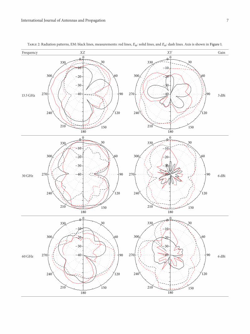
The measured and simulated radiation patterns andpeak gain of the proposed antenna at frequencies 13.5 GHz,30GHz, and 60GHz in the 𝑋𝑍 and 𝑋𝑌 planes are shown inTable 2.This table also shows the fair agreement of measuredand simulated patterns and gain. Discrepancy may be due tothe reflective bodies of automobiles that caused fluctuationsin readings; the movement and positioning of the coaxialcable altered patterns and mis-mounting of the antennascaused altered patterns. These errors increased especially athigh frequencies. The large cross polarization radiation isassumed to be generated by the balun and the use of the largeconnector.
International Journal of Antennas and Propagation 7
Table 2: Radiation patterns, EM: black lines, measurements: red lines, 𝐸B: solid lines, and 𝐸Θ: dash lines. Axis is shown in Figure 1.
Frequency 𝑋𝑍 𝑋𝑌 Gain
13.5 GHz
0 030
60
90
120
150180
210
240
270
300
330−10
−20
−30
−40
0 030
60
90
120
150180
210
240
270
300
330−10
−20
−30
−40 3 dBi
30GHz
0 030
60
90
120
150180
210
240
270
300
330−10
−20
−30
−40
0 030
60
90
120
150180
210
240
270
300
330−10
−20
−30
−40 6 dBi
60GHz
0 030
60
90
120
150180
210
240
270
300
330−10
−20
−30
−40
0 030
60
90
120
150180
210
240
270
300
330−10
−20
−30
−40 6 dBi
8 International Journal of Antennas and Propagation
10 20 30 40 50 60 70 800
10
20
30
40
50
60
70
80
90
100
Radi
atio
n effi
cien
cy (%
)
Frequency (GHz)
SimulatedMeasured
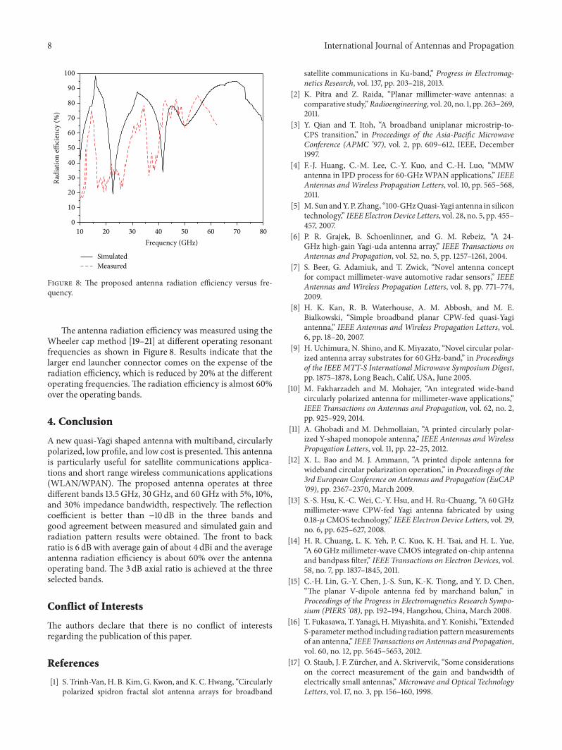
Figure 8: The proposed antenna radiation efficiency versus fre-quency.
The antenna radiation efficiency was measured using theWheeler cap method [19–21] at different operating resonantfrequencies as shown in Figure 8. Results indicate that thelarger end launcher connector comes on the expense of theradiation efficiency, which is reduced by 20% at the differentoperating frequencies. The radiation efficiency is almost 60%over the operating bands.
4. Conclusion
A new quasi-Yagi shaped antenna with multiband, circularlypolarized, low profile, and low cost is presented.This antennais particularly useful for satellite communications applica-tions and short range wireless communications applications(WLAN/WPAN). The proposed antenna operates at threedifferent bands 13.5 GHz, 30GHz, and 60GHz with 5%, 10%,and 30% impedance bandwidth, respectively. The reflectioncoefficient is better than −10 dB in the three bands andgood agreement between measured and simulated gain andradiation pattern results were obtained. The front to backratio is 6 dB with average gain of about 4 dBi and the averageantenna radiation efficiency is about 60% over the antennaoperating band. The 3 dB axial ratio is achieved at the threeselected bands.
Conflict of Interests
The authors declare that there is no conflict of interestsregarding the publication of this paper.
References
[1] S. Trinh-Van, H. B. Kim, G. Kwon, andK. C. Hwang, “Circularlypolarized spidron fractal slot antenna arrays for broadband
satellite communications in Ku-band,” Progress in Electromag-netics Research, vol. 137, pp. 203–218, 2013.
[2] K. Pıtra and Z. Raida, “Planar millimeter-wave antennas: acomparative study,”Radioengineering, vol. 20, no. 1, pp. 263–269,2011.
[3] Y. Qian and T. Itoh, “A broadband uniplanar microstrip-to-CPS transition,” in Proceedings of the Asia-Pacific MicrowaveConference (APMC ’97), vol. 2, pp. 609–612, IEEE, December1997.
[4] F.-J. Huang, C.-M. Lee, C.-Y. Kuo, and C.-H. Luo, “MMWantenna in IPD process for 60-GHzWPAN applications,” IEEEAntennas andWireless Propagation Letters, vol. 10, pp. 565–568,2011.
[5] M. Sun andY. P. Zhang, “100-GHzQuasi-Yagi antenna in silicontechnology,” IEEE ElectronDevice Letters, vol. 28, no. 5, pp. 455–457, 2007.
[6] P. R. Grajek, B. Schoenlinner, and G. M. Rebeiz, “A 24-GHz high-gain Yagi-uda antenna array,” IEEE Transactions onAntennas and Propagation, vol. 52, no. 5, pp. 1257–1261, 2004.
[7] S. Beer, G. Adamiuk, and T. Zwick, “Novel antenna conceptfor compact millimeter-wave automotive radar sensors,” IEEEAntennas and Wireless Propagation Letters, vol. 8, pp. 771–774,2009.
[8] H. K. Kan, R. B. Waterhouse, A. M. Abbosh, and M. E.Bialkowski, “Simple broadband planar CPW-fed quasi-Yagiantenna,” IEEE Antennas and Wireless Propagation Letters, vol.6, pp. 18–20, 2007.
[9] H. Uchimura, N. Shino, and K.Miyazato, “Novel circular polar-ized antenna array substrates for 60GHz-band,” in Proceedingsof the IEEE MTT-S International Microwave Symposium Digest,pp. 1875–1878, Long Beach, Calif, USA, June 2005.
[10] M. Fakharzadeh and M. Mohajer, “An integrated wide-bandcircularly polarized antenna for millimeter-wave applications,”IEEE Transactions on Antennas and Propagation, vol. 62, no. 2,pp. 925–929, 2014.
[11] A. Ghobadi and M. Dehmollaian, “A printed circularly polar-ized Y-shaped monopole antenna,” IEEE Antennas andWirelessPropagation Letters, vol. 11, pp. 22–25, 2012.
[12] X. L. Bao and M. J. Ammann, “A printed dipole antenna forwideband circular polarization operation,” in Proceedings of the3rd European Conference on Antennas and Propagation (EuCAP’09), pp. 2367–2370, March 2009.
[13] S.-S. Hsu, K.-C. Wei, C.-Y. Hsu, and H. Ru-Chuang, “A 60GHzmillimeter-wave CPW-fed Yagi antenna fabricated by using0.18-𝜇 CMOS technology,” IEEE Electron Device Letters, vol. 29,no. 6, pp. 625–627, 2008.
[14] H. R. Chuang, L. K. Yeh, P. C. Kuo, K. H. Tsai, and H. L. Yue,“A 60GHz millimeter-wave CMOS integrated on-chip antennaand bandpass filter,” IEEE Transactions on Electron Devices, vol.58, no. 7, pp. 1837–1845, 2011.
[15] C.-H. Lin, G.-Y. Chen, J.-S. Sun, K.-K. Tiong, and Y. D. Chen,“The planar V-dipole antenna fed by marchand balun,” inProceedings of the Progress in Electromagnetics Research Sympo-sium (PIERS ’08), pp. 192–194, Hangzhou, China, March 2008.
[16] T. Fukasawa, T. Yanagi, H.Miyashita, and Y. Konishi, “ExtendedS-parametermethod including radiation patternmeasurementsof an antenna,” IEEETransactions onAntennas and Propagation,vol. 60, no. 12, pp. 5645–5653, 2012.
[17] O. Staub, J. F. Zurcher, and A. Skrivervik, “Some considerationson the correct measurement of the gain and bandwidth ofelectrically small antennas,” Microwave and Optical TechnologyLetters, vol. 17, no. 3, pp. 156–160, 1998.

International Journal of Antennas and Propagation 9
[18] D. Titz, M. Kyro, C. Luxey, F. B. Abdeljelil, G. Jacquemod,and P. Vainikainen, “Radiation pattern measurement set-up for60GHz on-chip antennas,” in Proceedings of the 6th Loughbor-ough Antennas & Propagation Conference (LAPC ’10), pp. 533–536, IEEE, Loughborough, UK, November 2010.
[19] R. H. Johnston and J. G. McRory, “An improved small antennaradiation efficiency measurement method,” IEEE Antennas andPropagation Magazine, vol. 40, no. 5, pp. 40–47, 1998.
[20] A. P. Raiva and J. Fabrega-Sanchez, “A rectangular cavity forcell phone antenna efficiency measurement,” in Proceedings ofthe IEEE Antennas and Propagation Society International Sym-posium, pp. 740–743, July 2005.
[21] D. M. Pozar and B. Kaufman, “Comparison of three methodsfor the measurement of printed antenna efficiency,” IEEETransactions on Antennas and Propagation, vol. 36, no. 1, pp.136–139, 1988.
[22] H. G. Schantz, “Radiation efficiency of UWB antennas,” inProceedings of the IEEE Conference on Ultra Wideband Systemsand Technologies (UWBST ’02), pp. 351–355, Baltimore, Md,USA, May 2002.
[23] J. An, G.-M. Wang, C.-X. Zhang, and H.-Y. Zeng, “A compact,omni-directional, circularly polarized microstrip antenna,”Microwave Journal, vol. 53, no. 1, pp. 82–90, 2010.

International Journal of
AerospaceEngineeringHindawi Publishing Corporationhttp://www.hindawi.com Volume 2014
RoboticsJournal of
Hindawi Publishing Corporationhttp://www.hindawi.com Volume 2014
Hindawi Publishing Corporationhttp://www.hindawi.com Volume 2014
Active and Passive Electronic Components
Control Scienceand Engineering
Journal of
Hindawi Publishing Corporationhttp://www.hindawi.com Volume 2014
International Journal of
RotatingMachinery
Hindawi Publishing Corporationhttp://www.hindawi.com Volume 2014
Hindawi Publishing Corporation http://www.hindawi.com
Journal ofEngineeringVolume 2014
Submit your manuscripts athttp://www.hindawi.com
VLSI Design
Hindawi Publishing Corporationhttp://www.hindawi.com Volume 2014
Hindawi Publishing Corporationhttp://www.hindawi.com Volume 2014
Shock and Vibration
Hindawi Publishing Corporationhttp://www.hindawi.com Volume 2014
Civil EngineeringAdvances in
Acoustics and VibrationAdvances in
Hindawi Publishing Corporationhttp://www.hindawi.com Volume 2014
Hindawi Publishing Corporationhttp://www.hindawi.com Volume 2014
Electrical and Computer Engineering
Journal of
Advances inOptoElectronics
Hindawi Publishing Corporation http://www.hindawi.com
Volume 2014
The Scientific World JournalHindawi Publishing Corporation http://www.hindawi.com Volume 2014
SensorsJournal of
Hindawi Publishing Corporationhttp://www.hindawi.com Volume 2014
Modelling & Simulation in EngineeringHindawi Publishing Corporation http://www.hindawi.com Volume 2014
Hindawi Publishing Corporationhttp://www.hindawi.com Volume 2014
Chemical EngineeringInternational Journal of Antennas and
Propagation
International Journal of
Hindawi Publishing Corporationhttp://www.hindawi.com Volume 2014
Hindawi Publishing Corporationhttp://www.hindawi.com Volume 2014
Navigation and Observation
International Journal of
Hindawi Publishing Corporationhttp://www.hindawi.com Volume 2014
DistributedSensor Networks
International Journal of


