X-HTC-1001
Repair Parts
CATALOG
for SUNNEN® TUBE HONING MACHINES HTC SERIES HTC-1121 (Linear Feed) & HTC-2121 Version: VCS11/21 Date: 12 April, 2006
READ THE FOLLOWING INSTRUCTIONS THOROUGHLY AND CAREFULLY BEFORE UNPACKING, INSPECTING, OR INSTALLING THE HTB-TUBE-HONING-MACHINE.
“SUNNEN AND THE SUNNEN LOGO ARE REGISTERED TRADEMARKS OF SUNNEN PRODUCTS COMPANY.”
SUNNEN PRODUCTS COMPANY 7910 MANCHESTER ROAD SAINT LOUIS, MO 63143, U.S.A. PHONE: 314-781-2100
SUNNEN AG · Fabrikstrasse 1 · 8586 ENNETAACH · SWITZERLAND · PHONE: + 41 71 649 33 33
1
TABLE OF CONTENTS VCSS11
TABLE OF CONTENTS 1
INTRODUCTION 2
HOW TO ORDER 2
HOW TO USE THIS PARTS LIST 2
DRIVE MECHANISM LFS-110 4
DRIVE MECHANISM Spindle Nose Cover 6
DRIVE MECHANISM 2 7
STROKE MECHANISM 1 9
STROKE MECHANISM 2 11
MOVING SUPPORT 12
COVERS AND COOLANT 13
TOOL SUPPORT 15
HOLDING FIXTURE 16
ELECTRICAL 1, Drives (Diagram VCSS11) 18
ELECTRICAL 1, Drives (Diagram VCSS11) 19
ELECTRICAL 2, Upper Side (Diagram VCSS11) 20
ELECTRICAL 2, Upper Side (Diagram VCSS11) 21
ELECTRICAL 3, IPC-Control (Diagram VCSS11) 22
ELECTRICAL 4 (Diagram VCSS11) 23
PNEUMATIC SYSTEM (HTC-2) 25
PF-401 FILTER UNIT (Optional) 27
Like any machinery, this equipment may be dangerous if used improperly. Be sure to read and follow the instructions for the operation of the equipment.
2
INTRODUCTION Illustrations show all major components in exploded detail. Item numbers on each illustration are keyed to he�s corresponding parts list, providing a descriptive identification of each part. The parts list includes assemblies as well as detail parts. Items listed without a part number can be optioned as a component of the complete assembly of which it is a part. SUNNEN AG reserves the right to make changes, without notice, to materials, specifications, colors, designs and accessories includes with units.
HOW TO ORDER When ordering replacement parts are sure to include the following information to insure prompt shipment of correct parts:
1. The part number and description of each part desired, obtained from this parts catalog.
2. The quantity of each part desired.
3. The voltage, frequency and phases, when ordering electrical parts.
4. The model and serial number of the honing machine, obtained from the nameplate, when there is any question concerning a part.
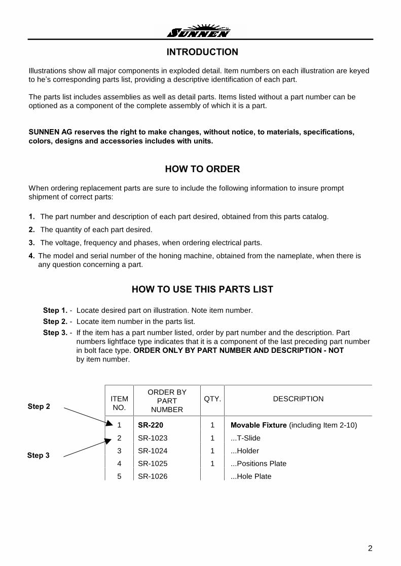
HOW TO USE THIS PARTS LIST
Step 1. - Locate desired part on illustration. Note item number.
Step 2. - Locate item number in the parts list.
Step 3. - If the item has a part number listed, order by part number and the description. Part numbers lightface type indicates that it is a component of the last preceding part number in bolt face type. ORDER ONLY BY PART NUMBER AND DESCRIPTION - NOT by item number.
ITEM NO.
ORDER BY PART
NUMBER
QTY.
DESCRIPTION
1 SR-220 1 Movable Fixture (including Item 2-10)
2 SR-1023 1 ...T-Slide
3 SR-1024 1 ...Holder
4 SR-1025 1 ...Positions Plate
5 SR-1026 ...Hole Plate
Step 2
Step 3

3

4
DRIVE MECHANISM LFS-110
PARTS LIST COVERING FIGURE � Drawing LFS-110 �
ITEM NO.
ORDER BY PART
NUMBER
QTY.
DESCRIPTION
1 LFS-1001-1 1 Gear Housing 2 LFS-1002 1 Wheel Z54 3 LFS-1004 1 Housing 4 LFS-1005 1 Ball Screw Housing 5 LFS-1106 1 Ball Screw Housing Cover 6 LFS-1107 1 Ball Screw Adapter 7 LFS-1108 2 Inner Disk 8 LFS-1109 2 Outer Disk
10 LFS-1011 1 Holder Sensor 11 LFS-1112 1 Axial Bearing Housing 12 LFS-1113 1 Axial Bearing Cover 13 LFS-1014 1 Ring 14 LFS-1115 1 Bar 15 LFS-1116 1 Spindle 16 LFS-1118 1 Feed Adapter 17 LFS-1120 1 Ring 18 LFS-1019 1 Ring 19 LFS-1121 1 Ring 20 LFS-1122 1 Spindle Housing 21 LFS-1125 1 Distance Ring 22 LFS-1124 1 Bearing Cover 23 LFS-1027 1 Ring 24 LFS-1128-1 1 Belt Cover 28 LFS-1150-1 1 Adapter Axial Bearing 29 LFS-1151-1 2 Tube 30 LFS-1152 1 Holder 31 7208BG 2 Bearing 32 7204B.TVP.UA 2 Bearing 33 6201 2RS 1 Bearing 34 6001 2Z 2 Bearing 35 1551-0-1700 1 Feed Spindle KGT D=20 5/0.052 T7, Length 198mm 36 1512-1-1013 1 Flansh Nut D=20x5
37 1590-0-1200 1 Bearing 38 0601-016-10 2 Ball Bearing ø 26/16x36 39 450 113 1 Feed Motor Coupling ø 10/11 (MK1-45-37-10-11) 40 32-8M-20 5F ST TB 1610 1 Tooth Belt Wheel Z32
5
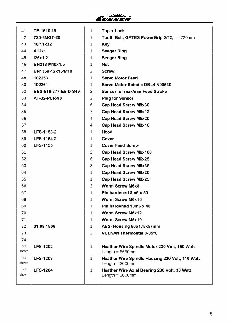
41 TB 1610 19 1 Taper Lock 42 720-8MGT-20 1 Tooth Belt, GATES PowerGrip GT2, L= 720mm 43 18/11x32 1 Key 44 A12x1 1 Seeger Ring 45 I26x1.2 1 Seeger Ring 46 BN218 M40x1.5 1 Nut 47 BN1359-12x16/M10 2 Screw 48 102253 1 Servo Motor Feed 50 102261 1 Servo Motor Spindle DBL4 N00530 52 BES-516-377-E5-D-S49 2 Sensor for max/min Feed Stroke 53 AT-32-PUR-90 2 Plug for Sensor 54 6 Cap Head Screw M8x30 55 7 Cap Head Screw M5x12 56 4 Cap Head Screw M5x20 57 4 Cap Head Screw M8x16 58 LFS-1153-2 1 Hood 59 LFS-1154-2 1 Cover 60 LFS-1155 1 Cover Feed Screw 61 2 Cap Head Screw M6x100 62 6 Cap Head Screw M6x25 63 3 Cap Head Screw M6x35 64 1 Cap Head Screw M8x20 65 1 Cap Head Screw M8x25 66 2 Worm Screw M6x8 67 1 Pin hardened 8m6 x 50 68 1 Worm Screw M6x16 69 1 Pin hardened 10m6 x 40 70 1 Worm Screw M6x12 71 1 Worm Screw M5x10 72 01.08.1806 1 ABS- Housing 80x175x57mm 73 2 VULKAN Thermostat 0-85°C 74 not
shown LFS-1202 1 Heather Wire Spindle Motor 230 Volt, 150 Watt
Length = 5650mm not
shown LFS-1203 1 Heather Wire Spindle Housing 230 Volt, 110 Watt
Length = 3000mm not
shown LFS-1204 1 Heather Wire Axial Bearing 230 Volt, 30 Watt
Length = 1000mm
6
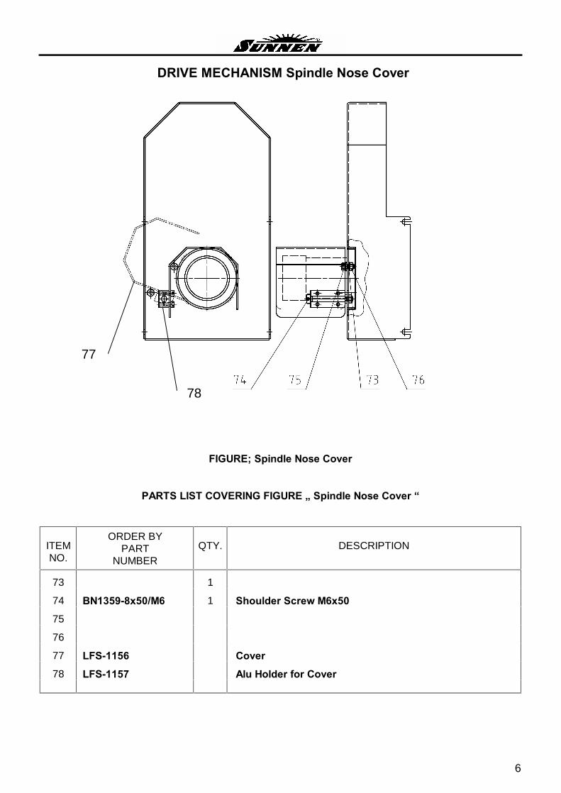
DRIVE MECHANISM Spindle Nose Cover
FIGURE; Spindle Nose Cover
PARTS LIST COVERING FIGURE � Spindle Nose Cover �
ITEM NO.
ORDER BY PART
NUMBER
QTY.
DESCRIPTION
73 1
74 BN1359-8x50/M6 1 Shoulder Screw M6x50
75
76
77 LFS-1156 Cover
78 LFS-1157 Alu Holder for Cover
77
78
7
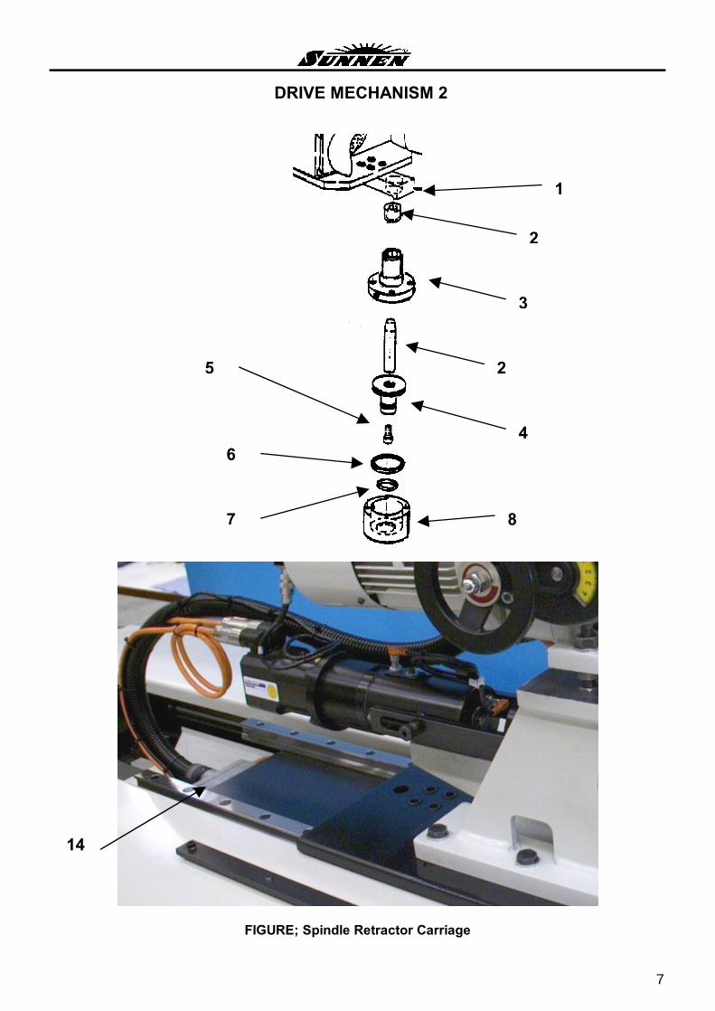
DRIVE MECHANISM 2
FIGURE; Spindle Retractor Carriage
2
3
8
4
2
7
6
5
14
1

8
DRIVE MECHANISM 2
PARTS LIST COVERING FIGURE � Spindle Retractor Carriage �
ITEM NO.
ORDER BY PART
NUMBER
QTY.
DESCRIPTION
1 HT-2002 1 Lock Bolt Plate
2 HT-2005-1 1 Lock Bolt and Taper Sleeve
3 HT-2004 1 Lock Bolt Sleeve
4 HT-2008 1 Piston
5 JZK M10x20 1 Cap Head Screw
6 11 6241 0110 1 Airzet Seal ø 60
7 11 6241 0107 1 Airzet Seal ø 40
8 HT-2006 1 Air Cylinder Housing not
shown HT-2007 1 Air Cylinder Cover not
shown 60x2 1 O-Ring
14 0934 010 0404 0934 016 2601
1 Plug male (X121)
not shown
0934 010 0304 0934 016 2701
1 Plug female (X121)
not shown XCM-B515 2 Safety Switch S716L / S716R (Pkg. of 1)
not shown 0731-240-40 4 Linear Bearings (Pkg. of 1)
not shown AT-32-PUR-90 1 Plug for Sensor
not shown I3N-M8TIS-PO6 1 Sensor Initialization

9
STROKE MECHANISM 1
FIGURE; Chain Adjuster
1
2
8
9
7
3
4
6
10
STROKE MECHANISM 1
PARTS LIST COVERING FIGURE � Chain Adjuster �
ITEM NO.
ORDER BY PART
NUMBER
QTY.
DESCRIPTION
1 HT-2112 1 Duplex Chain Wheel with two Bearings
2 HT-3018 2 Spacer
3 HT-3019 1 Bolt
4 HT-3017 1 Duplex Chain Adjuster
6 MF-30x2x200 1 Spindle
7 HT-2046 1 Washer
8 MF-30x2-M 2 Nut
9 HT-3038 1 Chain Guard not
shown HT-3020 1 Damper Holder not
shown HT-3025 1 Back Stop Washer not
shown 12.2101.0403 1 Damper not
shown JZK-M12x80 1 Cap Head Screw

11
STROKE MECHANISM 2
FIGURE; Stroke Drive
ITEM NO.
ORDER BY PART
NUMBER
QTY.
DESCRIPTION
1 RLD 1600 5571 1 Clamp Sleeve ø 55 / 71
2 HT-2110 1 Duplex Chain Wheel
3 HT-3004-1 1 Gear Flansh with Screws
4 16B-2 Duplex Chain 1�x17mm (Pkg. of 1 meter)
5 16B-2NR3 1 Chain Locker
6 C9DE0026/CYD32615 Stroke Gear MT ø 55x80 (i=26)
8 30069 ZHAA 1 Coupling ø 24/24
9 81679 1 Servomotor Stroke 3,0 kW (6SM 71K-3,000)

12
MOVING SUPPORT
FIGURE; Moving Support
ITEM NO.
ORDER BY PART
NUMBER
QTY.
DESCRIPTION
1 SR-1060 1 Guide-Shells ø 5mm
1 SR-1061 1 Guide-Shells ø 7mm
1 SR-1062 1 Guide-Shells ø 7mm
1 SR-1063 1 Guide-Shells ø 13mm
1 SR-1064 1 Guide-Shells ø 16mm
2 SR-1057 1 Holder for LFS-Guide
3 SR-1010 1 Guide Holder
4 GN617-6-AK 1 Position Bolt
5 1607-204-31 1 Rail
6 1691-294-10 1 Linear Bearing not
shown VK332-5DO-M5 1 3/2 Air Valve Y2001 (Moving Support) not
shown K33 1 Plug (Moving Support) not
shown EVM130-F01-00 1 3/2 Air Valve mechanical
7 C85N25-10C00 1 Air Cylinder (Moving Support) not
shown EAR-2000_F01 2 Regulator (Moving Support)
1
2
3
4
5
6
7
13
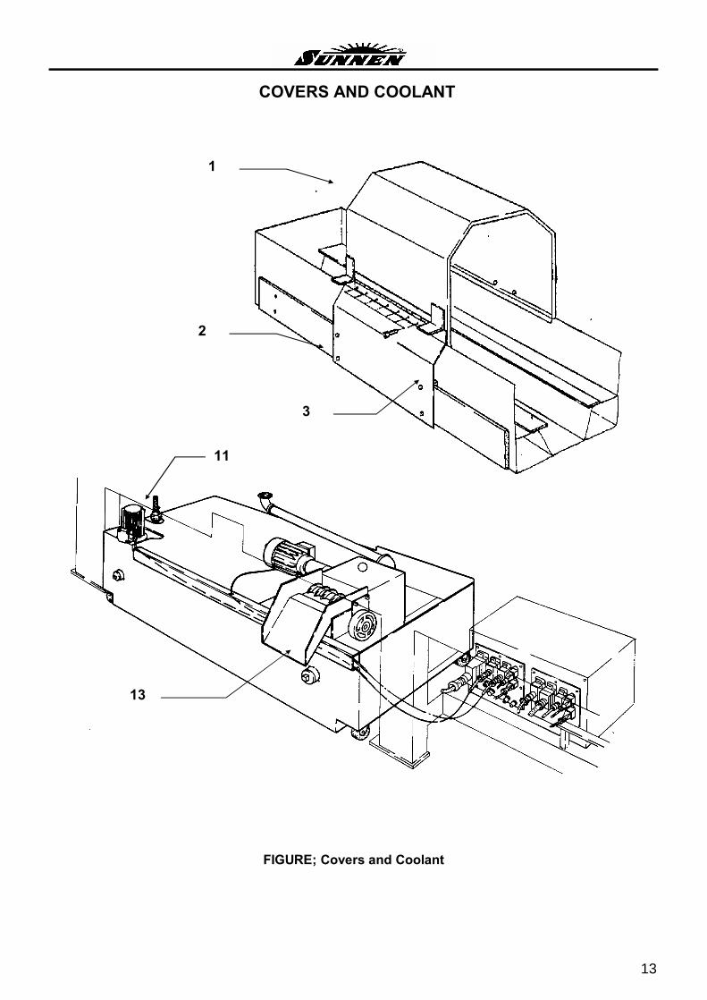
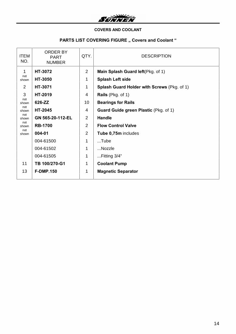
COVERS AND COOLANT
FIGURE; Covers and Coolant
1
3
2
13
11
14
COVERS AND COOLANT
PARTS LIST COVERING FIGURE � Covers and Coolant �
ITEM NO.
ORDER BY PART
NUMBER
QTY.
DESCRIPTION
1 HT-3072 2 Main Splash Guard left(Pkg. of 1) not
shown HT-3050 1 Splash Left side
2 HT-3071 1 Splash Guard Holder with Screws (Pkg. of 1)
3 HT-2019 4 Rails (Pkg. of 1) not
shown 626-ZZ 10 Bearings for Rails not
shown HT-2045 4 Guard Guide green Plastic (Pkg. of 1) not
shown GN 565-20-112-EL 2 Handle not
shown RB-1700 2 Flow Control Valve not
shown 004-01 2 Tube 0,75m includes
004-61500 1 ...Tube
004-61502 1 ...Nozzle
004-61505 1 ...Fitting 3/4�
11 TB 100/270-G1 1 Coolant Pump
13 F-DMP.150 1 Magnetic Separator
15
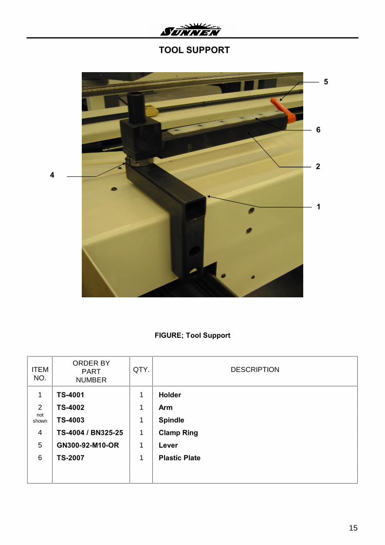
TOOL SUPPORT
FIGURE; Tool Support
ITEM NO.
ORDER BY PART
NUMBER
QTY.
DESCRIPTION
1 TS-4001 1 Holder
2 TS-4002 1 Arm not
shown TS-4003 1 Spindle
4 TS-4004 / BN325-25 1 Clamp Ring
5 GN300-92-M10-OR 1 Lever
6 TS-2007 1 Plastic Plate
1
4
6
2
5
16
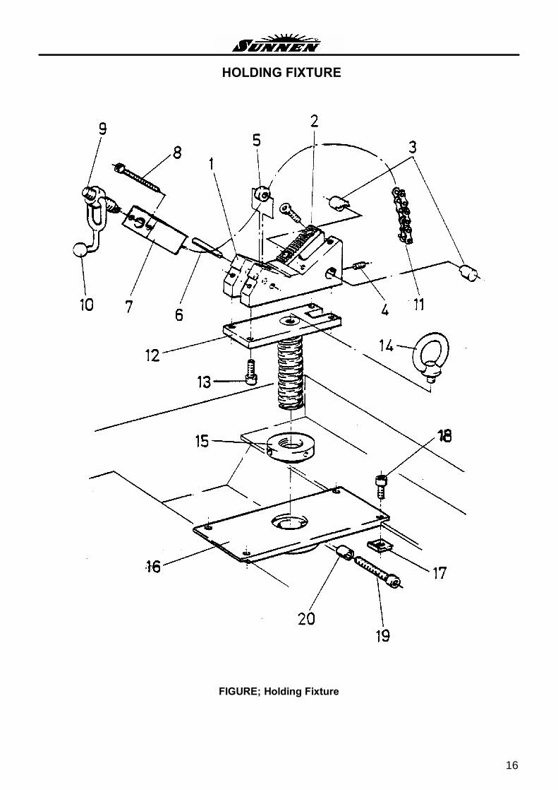
HOLDING FIXTURE
FIGURE; Holding Fixture
17
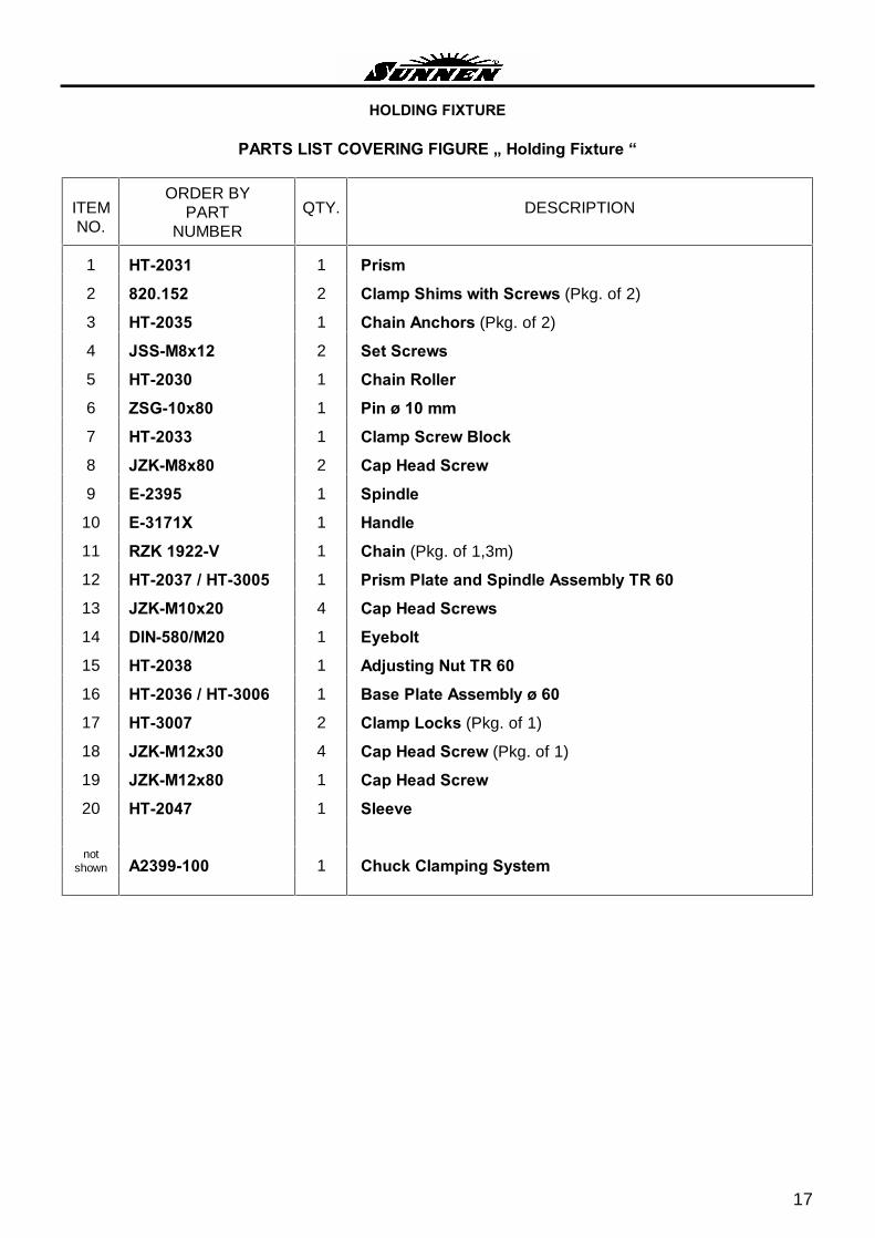
HOLDING FIXTURE
PARTS LIST COVERING FIGURE � Holding Fixture �
ITEM NO.
ORDER BY PART
NUMBER
QTY.
DESCRIPTION
1 HT-2031 1 Prism
2 820.152 2 Clamp Shims with Screws (Pkg. of 2)
3 HT-2035 1 Chain Anchors (Pkg. of 2)
4 JSS-M8x12 2 Set Screws
5 HT-2030 1 Chain Roller
6 ZSG-10x80 1 Pin ø 10 mm
7 HT-2033 1 Clamp Screw Block
8 JZK-M8x80 2 Cap Head Screw
9 E-2395 1 Spindle
10 E-3171X 1 Handle
11 RZK 1922-V 1 Chain (Pkg. of 1,3m)
12 HT-2037 / HT-3005 1 Prism Plate and Spindle Assembly TR 60
13 JZK-M10x20 4 Cap Head Screws
14 DIN-580/M20 1 Eyebolt
15 HT-2038 1 Adjusting Nut TR 60
16 HT-2036 / HT-3006 1 Base Plate Assembly ø 60
17 HT-3007 2 Clamp Locks (Pkg. of 1)
18 JZK-M12x30 4 Cap Head Screw (Pkg. of 1)
19 JZK-M12x80 1 Cap Head Screw
20 HT-2047 1 Sleeve
not
shown A2399-100 1 Chuck Clamping System

18
ELECTRICAL 1, Drives (Diagram VCSS11)
FIGURE; Electrical 1
T410 K706
A110 A120
K2016
A130

19
ELECTRICAL 1, Drives (Diagram VCSS11)
PARTS LIST COVERING FIGURE � Electrical 1 �
DIAGRAM NO.
ORDER BY PART
NUMBER
QTY.
DESCRIPTION
A110 (Stroke) 89703 1 Speed Regulator
SERVOSTAR 610-AS
A120 (Feed) 89701 1 Speed Regulator
SERVOSTAR 603
A130 (Stroke) 89703 1 Speed Regulator
SERVOSTAR 610-AS
T410 6EP14363BA00 1 SITOP Power 24 Volt / ??A
K706 DIL 1M-G(24VDC) 1 Contactor
K706 22 DIL M 1 Sub Contactor
K2016 DIL EM-10-G(24VDC) 1 Contactor
Outside of ELECTRICAL ENCLOSURE
ITEM NO.
DIAGRAM NO.
ORDER BY PART
NUMBER
QTY.
DESCRIPTION
S711, S712 10721S 1 Sender of Light Barrier SLA25
S711A, S712A 10721E 1 Receiver of Light Barrier SLA25 with LED

20
ELECTRICAL 2, Upper Side (Diagram VCSS11)
FIGURE; Electrical 2
A403
S100
A711
K705
F414
K2011
A1000-1030
K2009
F317
Q103a
Q110
Q411
Q314
K2026
F413
Q312 Q311
A702
X2009
F401
F402
K2014
K2027
K2028
K2008
Q..
K2022

21
ELECTRICAL 2, Upper Side (Diagram VCSS11)
PARTS LIST COVERING FIGURE � Electrical 2 �
DIAGRAM NO.
ORDER BY PART
NUMBER
QTY.
DESCRIPTION
A403 IPC HTC MKV-0 1 IPC-Control SK3150 100 1 Air Van S100 P3-63/EA/SVB-SW/N 1 Main Switch A711 SLVA-4K 1 Light Barrier Control 24VDC A1000, A1010, A1020, A1030
DC8I8O50 4 I/O OPTO-Conditioner
A1000, A1010, A1020, A1030
FBK26P 4 Flat Wire to OPTO-Conditioner
A702 PNOZ/475695 1 Emergency Stop Control K2011, K2014, K2026, K2027, K2028, K2008, K2022
C9-A41DX (24VDC) 7 Relays (COMAT)
K2009 DIL ER-22-G(24VDC) 1 Contactor X2009 DEK-OE-
24DC/48DC/100 1 Optokoppler
F413, F414 FAZNC10 2 Circuit Breaker 10A Q103A CL-PKZO 1 Supply Limiter Q411 PKZM0-1.6 1 Manual Starter 1.6A Q110 PKZM0-25 1 Manual Starter 25A Q311 PKZM0-1.0 1 Manual Starter 1,0A Q312 PKZM0-0.63 1 Manual Starter 0,63A
(Machines 1 up to 3 Meters)
Q312 PKZM0-1.0 1 Manual Starter 1,0A (Machines with 500 Liter Coolant Reservoir)
Q311, Q312, Q314 NHI 11-PKZ0 3 Contactor to Manual Starters F317, F401, F402 FAZNC10-N 3 Circuit Breaker C10A&NT

22
ELECTRICAL 3, IPC-Control (Diagram VCSS11)
FIGURE; Electrical 3
PARTS LIST COVERING FIGURE � Electrical 3 �
DIAGRAM NO. ORDER BY PART NO. QTY. DESCRIPTION
A403 IPC HTC MKV-0 1 IPC-Control 2 IBMM20 1 ...IBM-Motherboard
3 STDMO20 1 ...STD-Motherboard
4 IBMSTD20 1 ...IBM-STD-Adapter
5 STD/CPU586 1 ...PENTIUM CPU AP-545V 233MHz
6 IBM-VGA 1 ...VGA-Controller
J1 / J2 STD/IO3220 1 ...I/O-Interface
J150 STD/4AD30 1 ...Digital-Analog Interface (Spindle Torque Controller) Version: WAAGAD10
J170 STD/SODA30 1 ...Digital-Analog Interface (Feed Torque Control)
J160 STD/SODA30 1 ...Digital-Analog Interface (Spindle Speed Control)
J7, J122 STD/SMCIO 422-S 1 ...Motor controller inc. Interrupt (Feed Control)
J11, J112 STD/SMCIO 422-S 1 ...Motor controller inc. Interrupt (Stroke Control)
13 C6510020 1 ...LCD-Sender SIL (new)
14 IPC-Netzteil 1 ...IPC-Supply
15 HDD 350M 1 ...Harddisk drive
16 FD 1.44M 1 ...Floppy drive
1
2
3
4
5
6
16
15
13
14
J1 / J2 J150 J170 J160 J7, J122
J11, J112

23
ELECTRICAL 4 (Diagram VCSS11)
FIGURE O; Electrical 4
8
3
9
14
16
2
6 19
18
17
20
11
4
7
13
10
12
5
15

24
ELECTRICAL 4 (Diagram VCSS11)
PARTS LIST COVERING FIGURE �O�
ITEM NO.
DIAGRAM NO.
ORDER BY PART
NUMBER
QTY.
DESCRIPTION
1 A401 Panel HTC-VC-45 1 Operator Panel
2 FP HTC MKV-1 1 Front plate with Foil and Frame
3 A7005 LQ10D321 1 Color LCD-Display TFT
4 A7003 LQ10D321 IN 1 Back light Inverter S/N until 1744
4 A7003 CXA-LO612-VSL 1 Back light Inverter S/N 1748 and up
5 LQOB128 1 Back light
6 E274HL-683 (OBSOLETE) 1 Touch screen
6 HTC-TOUCH4 1 Touch screen including Frame
7 A7007 E271-2210 1 Touch Controller
8 A7008 STC3TG10 1 Numeric Keyboard
9 STC3TK10 1 Functions Keyboard F1 � F10
10 PPCKBW10 1 Keyboard Point
11 T402 SNP9541 1 Panel-Power Supply
12 C6510120 1 LCD-Receiver SIL
13 K2021 C9-A41X (24VDC) 1 Relays (COMAT)
14 S717 ZB4-BS54 1 Emergency Stop Switch
14 S717 ZB4-BZ104 1 Contacts
15 S1031 XB4-BD53 1 Feed Switch
Including Contacts
16 S1033, S1034 ZB4-BA38 2 Key Left / Right GREEN
16 S1033, S1034 ZB4-BZ101 2 Contact
17 S1035, S1036 ZB4-BA38 2 Acknowledge Key GREEN
17 S1035, S1036 ZB4-BZ101 2 Contact
18 S1037 ZB4-BA38 1 Start Key GREEN
18 S1037 ZB4-BZ101 1 Contact
19 S1038 ZB4-BA48 1 Stop Key RED
19 S1038 ZB4-BZ102 1 Contact
20 S1039 ZB4-BA68 1 Reset Key BLUE
20 S1039 ZB4-BW0B61 1 Contact

25
PNEUMATIC SYSTEM (HTC-2)
26
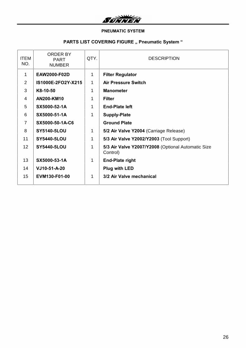
PNEUMATIC SYSTEM
PARTS LIST COVERING FIGURE � Pneumatic System �
ITEM NO.
ORDER BY PART
NUMBER
QTY.
DESCRIPTION
1 EAW2000-F02D 1 Filter Regulator
2 IS1000E-2FO2Y-X215 1 Air Pressure Switch
3 K8-10-50 1 Manometer
4 AN200-KM10 1 Filter
5 SX5000-52-1A 1 End-Plate left
6 SX5000-51-1A 1 Supply-Plate
7 SX5000-50-1A-C6 Ground Plate
8 SY5140-5LOU 1 5/2 Air Valve Y2004 (Carriage Release)
11 SY5440-5LOU 1 5/3 Air Valve Y2002/Y2003 (Tool Support)
12 SY5440-5LOU 1 5/3 Air Valve Y2007/Y2008 (Optional Automatic Size Control)
13 SX5000-53-1A 1 End-Plate right
14 VJ10-51-A-20 Plug with LED
15 EVM130-F01-00 1 3/2 Air Valve mechanical
27
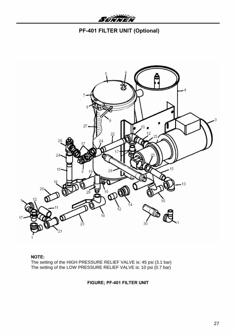
PF-401 FILTER UNIT (Optional)
NOTE: The setting of the HIGH PRESSURE RELIEF VALVE is: 45 psi (3.1 bar) The setting of the LOW PRESSURE RELIEF VALVE is: 10 psi (0.7 bar)
FIGURE; PF-401 FILTER UNIT

Note: If 5 micron filter elements are required, order PF-105-4. 28
PF-401 FILTER UNIT
PARTS LIST COVERING FIGURE � PF-401 FILTER UNIT �
ITEM NO.
ORDER BY PART
NUMBER
QTY.
DESCRIPTION
1 CK-1279A 3 Street Elbow (3/4 NPT) Pkg. of 1
2 CK-1389A 1 Relief Valve (High Pressure)
3 CK-5724 1 Pump Motor (50Hz)
3 CK-5721 1 Pump Motor (60Hz)
4 PF-405 1 Canister
5 PF-243 2 Cover
6 PF-246A 2 Air Vent Pkg. of 1
7 PF-244 2 Clamp Ring
8 PF-261 2 Clamp
9 PF-270A 2 Tee Handle Pkg. of 1
10 PF-259A 2 Draincock Pkg. of 1
11 PF-426A 1 Hose
12 PPP-152A 3 Nipple (3/4 NPT) Pkg. of 1
13 PPP-154A 2 Side Outlet Elbow (3/4 NPT) Pkg. of 1
14 PPP-168A 1 Reducer Coupling (3/4 to 1�)
15 PPP-195A 1 Nipple (3/4 NPT x 4 �Long)
16 PPP-196A 2 Street Tee (3/4 NPT) Pkg. of 1
17 PPP-197A 4 Swivel Adapter (3/4-14 NPT) Pkg. of 1
18 PPP-198A 1 Valve (3 Way)
19 PPP-199A 1 Shutoff Valve
20 PPP-200A 1 Nipple (3/4-14 NPT x 3 Long)
21 PPP-201A 1 Tee (3/4-14 NPT)
22 PPP-204A 1 Nipple (3/4-14 NPT x 5-3/4 Long)
23 PPP-205A 1 Nipple (3/4-14 NPT x 6-1/2 Long)
24 PPP-209A 2 Coupling (3/4 NPT)
25 PPP-M445 2 Coupling
26 PPP-208A 1 Relive Valve (Low Pressure)
27 PF-110-4* 1 Filter Elements (10-Micron) Pkg. of 4
28 PPP-37A 1 Hose Assembly
29 PPP-39A 1 Hose Assembly
30 PPP-43A 1 Hose Assembly not
shown PPP-45A 1 Hose Assembly not
shown PF-440A 1 Intake Strainer & Hose Assembly

29
* NOTES

NOTES
SUNNEN®
reserves the right to change or revise specifications and product design in connection with any feature of our products contained herein. Such changes do not entitle the buyer to corresponding changes, improvements, additions, or replacements for equipment, supplies or accessories previously sold. Information contained herein is considered to be accurate based on available information at the time of printing. Should any discrepancy of information arise, Sunnen recommends that the user verify the discrepancy with Sunnen before proceeding.
PRINTED IN U.S.A. 0606 © COPYRIGHT SUNNEN® PRODUCTS COMPANY 2006, ALL RIGHTS RESERVED
SUNNEN PRODUCTS COMPANY 7910 ManchesterRoad • St. Louis, MO 63143 U.S.A. Phone: 314-781-2100 Fax: 314-781-2268 U.S.A. Toll-Free Sales and Service - Auto: 1-800-772-2878 • Ind: 1-800-325-3670 International Division - Telex: 4312052 SUNNEN PRODSTL http://www.sunnen.com e-mail: [email protected]
SUNNEN PRODUCTS LIMITED No. 1 Centro, Maxted Road Hemel Hempstead, Herts HP2 7EF ENGLAND Phone: ++ 44 1442 39 39 39 Fax: ++ 44 1442 39 12 12 www.sunnen.co.uk e-mail: [email protected] SUNNEN AG Fabrikstrasse 1 8586 Ennetaach-Erlen, Switzerland Phone: ++ 41 71 649 33 33 Fax: ++ 41 71 649 34 34 www.sunnen.ch e-mail: [email protected] SHANGHAI SUNNEN MECHANICAL CO., LTD. 889 Kang Qiao East Road, PuDong Shanghai 201319, P.R. China Phone: 86 21 5 813 3322 Fax: 86 21 5 813 2299 www.sunnensh.com e-mail: [email protected] SUNNEN ITALIA S.R.L. Viale Stelvio 12/15 20021 Ospiate di Bollate (MI) Italy Phone: 39 02 383 417 1 Fax: 39 02 383 417 50 www.sunnenitalia.com e-mail: [email protected]


