
No.:
PROJECT CLIENT
REFERENCES:
REVISIONS:No.: By: Date:
0 JRK 10-Sep-15
DRAWN BY:
TCB
DATE:
14-May-15 DWG. #: SHEET: REV.: SCALE:
1 OF 8 0 NONE
TITLE:
PROJECT
FIO
15515 Starling Crossing Lithia, Floride33547 (813) 654-
9800 www.boksamarinedesign.com
408-800-01
REVISIONS:
INITIAL RELEASE FOR REGULATORY REVIEW
AC LOAD ANALYSIS

9/11/2015 FIO 78 RESEARCH VESSELAC ELECTRICAL LOAD ANALYSIS - SUMMARY
LOAD kW 48.42 LOAD kW 46.93 LOAD kW 47.31 LOAD kW 31.85 LOAD kW 28.99HARBOR - ANCHOR - NIGHTHARBOR - ANCHOR - DAY
SUMMER CONDITIONSAC LOADS - SAILING AC LOADS - MANOEUVRING AC LOADS - HARBOR
SAILING - DAY SAILING - NIGHT MANOEUVRING
12.0%
88.0%
AVAILABLE
USED
14.7%
85.3%
AVAILABLE
USED
14.0%
86.0%
AVAILABLE
USED
42.1%
57.9%
AVAILABLE
USED
47.3%
52.7%
AVAILABLE
USED
BOKSA MARINE DESIGN - TCB PAGE 2 OF 9
POWER AVAILABLE POWER USED POWER AVAILABLE POWER USED POWER AVAILABLE POWER USED POWER AVAILABLE POWER USED POWER AVAILABLE POWER USED# OF GENERATORS RATING Kw # OF GENERATORS RATING Kw # OF GENERATORS RATING Kw # OF GENERATORS RATING Kw # OF GENERATORS RATING Kw
1 55.00 1 55.00 1 55.00 1 55.00 1 55.00
AVAILABLE USED AVAILABLE USED AVAILABLE USED AVAILABLE USED AVAILABLE USED12.0% 88.0% 14.7% 85.3% 14.0% 86.0% 42.1% 57.9% 47.3% 52.7%
LOAD kW 52.61 LOAD kW 49.76 LOAD kW 51.51 LOAD kW 34.72 LOAD kW 30.49SAILING - NIGHT MANOEUVRING
% LOADING% LOADING
WINTER CONDITIONS
% LOADING % LOADING % LOADING
AC LOADS - SAILING AC LOADS - MANOEUVRING AC LOADS - HARBOR - GENERATOR
HARBOR - ANCHOR - DAY HARBOR - ANCHOR - NIGHTSAILING - DAY
4.3%
9.5%
6.3%
POWER AVAILABLE POWER USED POWER AVAILABLE POWER USED POWER AVAILABLE POWER USED POWER AVAILABLE POWER USED POWER AVAILABLE POWER USED# OF GENERATORS RATING Kw # OF GENERATORS RATING Kw # OF GENERATORS RATING Kw # OF GENERATORS RATING Kw # OF GENERATORS RATING Kw
1 55.00 1 55.00 1 55.00 1 55.00 1 55.00
AVAILABLE USED AVAILABLE USED AVAILABLE USED AVAILABLE USED AVAILABLE USED4.3% 95.7% 9.5% 90.5% 6.3% 93.7% 36.9% 63.1% 44.6% 55.4%
% LOADING % LOADING % LOADING % LOADING % LOADING
95.7%
AVAILABLE
USED
90.5%
AVAILABLE
USED
93.7%
AVAILABLE
USED
36.9%
63.1%
AVAILABLE
USED
44.6%
55.4%
AVAILABLE
USED
BOKSA MARINE DESIGN - TCB 2 of 8
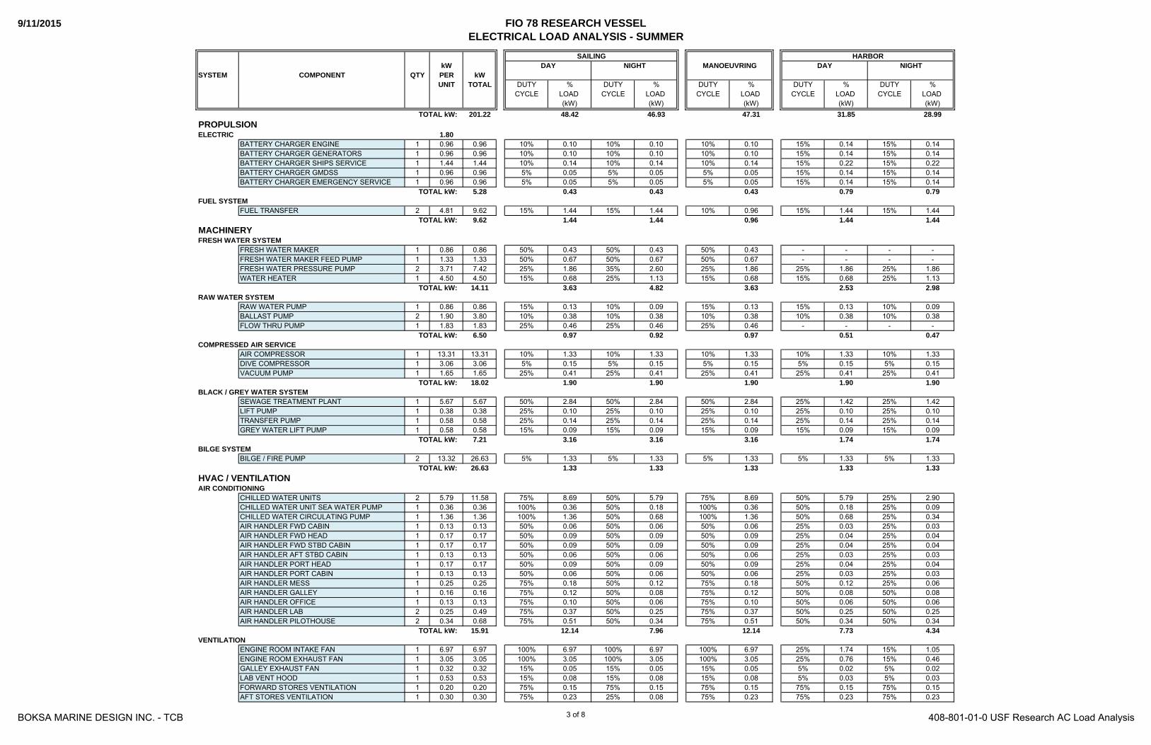
9/11/2015 FIO 78 RESEARCH VESSELELECTRICAL LOAD ANALYSIS - SUMMER
kWSYSTEM COMPONENT QTY PER kW
UNIT TOTAL DUTY % DUTY % DUTY % DUTY % DUTY %CYCLE LOAD CYCLE LOAD CYCLE LOAD CYCLE LOAD CYCLE LOAD
(kW) (kW) (kW) (kW) (kW)201.22 48.42 46.93 47.31 31.85 28.99
1.80BATTERY CHARGER ENGINE 1 0.96 0.96 10% 0.10 10% 0.10 10% 0.10 15% 0.14 15% 0.14BATTERY CHARGER GENERATORS 1 0.96 0.96 10% 0.10 10% 0.10 10% 0.10 15% 0.14 15% 0.14BATTERY CHARGER SHIPS SERVICE 1 1.44 1.44 10% 0.14 10% 0.14 10% 0.14 15% 0.22 15% 0.22BATTERY CHARGER GMDSS 1 0.96 0.96 5% 0.05 5% 0.05 5% 0.05 15% 0.14 15% 0.14BATTERY CHARGER EMERGENCY SERVICE 1 0.96 0.96 5% 0.05 5% 0.05 5% 0.05 15% 0.14 15% 0.14
5.28 0.43 0.43 0.43 0.79 0.79
FUEL TRANSFER 2 4.81 9.62 15% 1.44 15% 1.44 10% 0.96 15% 1.44 15% 1.449.62 1.44 1.44 0.96 1.44 1.44
FRESH WATER MAKER 1 0.86 0.86 50% 0.43 50% 0.43 50% 0.43 - - - -FRESH WATER MAKER FEED PUMP 1 1.33 1.33 50% 0.67 50% 0.67 50% 0.67 - - - -FRESH WATER PRESSURE PUMP 2 3.71 7.42 25% 1.86 35% 2.60 25% 1.86 25% 1.86 25% 1.86WATER HEATER 1 4.50 4.50 15% 0.68 25% 1.13 15% 0.68 15% 0.68 25% 1.13
14.11 3.63 4.82 3.63 2.53 2.98
RAW WATER PUMP 1 0.86 0.86 15% 0.13 10% 0.09 15% 0.13 15% 0.13 10% 0.09BALLAST PUMP 2 1.90 3.80 10% 0.38 10% 0.38 10% 0.38 10% 0.38 10% 0.38FLOW THRU PUMP 1 1.83 1.83 25% 0.46 25% 0.46 25% 0.46 - - - -
6.50 0.97 0.92 0.97 0.51 0.47
AIR COMPRESSOR 1 13.31 13.31 10% 1.33 10% 1.33 10% 1.33 10% 1.33 10% 1.33DIVE COMPRESSOR 1 3.06 3.06 5% 0.15 5% 0.15 5% 0.15 5% 0.15 5% 0.15VACUUM PUMP 1 1.65 1.65 25% 0.41 25% 0.41 25% 0.41 25% 0.41 25% 0.41
18.02 1.90 1.90 1.90 1.90 1.90
SEWAGE TREATMENT PLANT 1 5.67 5.67 50% 2.84 50% 2.84 50% 2.84 25% 1.42 25% 1.42LIFT PUMP 1 0.38 0.38 25% 0.10 25% 0.10 25% 0.10 25% 0.10 25% 0.10TRANSFER PUMP 1 0.58 0.58 25% 0.14 25% 0.14 25% 0.14 25% 0.14 25% 0.14GREY WATER LIFT PUMP 1 0.58 0.58 15% 0.09 15% 0.09 15% 0.09 15% 0.09 15% 0.09
7.21 3.16 3.16 3.16 1.74 1.74BILGE SYSTEM
BILGE / FIRE PUMP 2 13.32 26.63 5% 1.33 5% 1.33 5% 1.33 5% 1.33 5% 1.3326.63 1.33 1.33 1.33 1.33 1.33
CHILLED WATER UNITS 2 5.79 11.58 75% 8.69 50% 5.79 75% 8.69 50% 5.79 25% 2.90CHILLED WATER UNIT SEA WATER PUMP 1 0.36 0.36 100% 0.36 50% 0.18 100% 0.36 50% 0.18 25% 0.09CHILLED WATER CIRCULATING PUMP 1 1.36 1.36 100% 1.36 50% 0.68 100% 1.36 50% 0.68 25% 0.34AIR HANDLER FWD CABIN 1 0.13 0.13 50% 0.06 50% 0.06 50% 0.06 25% 0.03 25% 0.03AIR HANDLER FWD HEAD 1 0.17 0.17 50% 0.09 50% 0.09 50% 0.09 25% 0.04 25% 0.04AIR HANDLER FWD STBD CABIN 1 0.17 0.17 50% 0.09 50% 0.09 50% 0.09 25% 0.04 25% 0.04AIR HANDLER AFT STBD CABIN 1 0.13 0.13 50% 0.06 50% 0.06 50% 0.06 25% 0.03 25% 0.03AIR HANDLER PORT HEAD 1 0.17 0.17 50% 0.09 50% 0.09 50% 0.09 25% 0.04 25% 0.04AIR HANDLER PORT CABIN 1 0.13 0.13 50% 0.06 50% 0.06 50% 0.06 25% 0.03 25% 0.03AIR HANDLER MESS 1 0.25 0.25 75% 0.18 50% 0.12 75% 0.18 50% 0.12 25% 0.06AIR HANDLER GALLEY 1 0.16 0.16 75% 0.12 50% 0.08 75% 0.12 50% 0.08 50% 0.08AIR HANDLER OFFICE 1 0.13 0.13 75% 0.10 50% 0.06 75% 0.10 50% 0.06 50% 0.06AIR HANDLER LAB 2 0.25 0.49 75% 0.37 50% 0.25 75% 0.37 50% 0.25 50% 0.25AIR HANDLER PILOTHOUSE 2 0.34 0.68 75% 0.51 50% 0.34 75% 0.51 50% 0.34 50% 0.34
15.91 12.14 7.96 12.14 7.73 4.34
ENGINE ROOM INTAKE FAN 1 6.97 6.97 100% 6.97 100% 6.97 100% 6.97 25% 1.74 15% 1.05ENGINE ROOM EXHAUST FAN 1 3.05 3.05 100% 3.05 100% 3.05 100% 3.05 25% 0.76 15% 0.46GALLEY EXHAUST FAN 1 0.32 0.32 15% 0.05 15% 0.05 15% 0.05 5% 0.02 5% 0.02LAB VENT HOOD 1 0.53 0.53 15% 0.08 15% 0.08 15% 0.08 5% 0.03 5% 0.03FORWARD STORES VENTILATION 1 0.20 0.20 75% 0.15 75% 0.15 75% 0.15 75% 0.15 75% 0.15AFT STORES VENTILATION 1 0.30 0.30 75% 0.23 25% 0.08 75% 0.23 75% 0.23 75% 0.23
MANOEUVRING
TOTAL kW:
DAYSAILING
NIGHT
PROPULSIONELECTRIC
TOTAL kW:
TOTAL kW:FUEL SYSTEM
TOTAL kW:MACHINERYFRESH WATER SYSTEM
TOTAL kW:RAW WATER SYSTEM
TOTAL kW:COMPRESSED AIR SERVICE
TOTAL kW:BLACK / GREY WATER SYSTEM
TOTAL kW:
TOTAL kW:HVAC / VENTILATIONAIR CONDITIONING
HARBORDAY NIGHT
VENTILATION
BOKSA MARINE DESIGN INC. - TCB 408-801-01-0 USF Research AC Load Analysis3 of 8
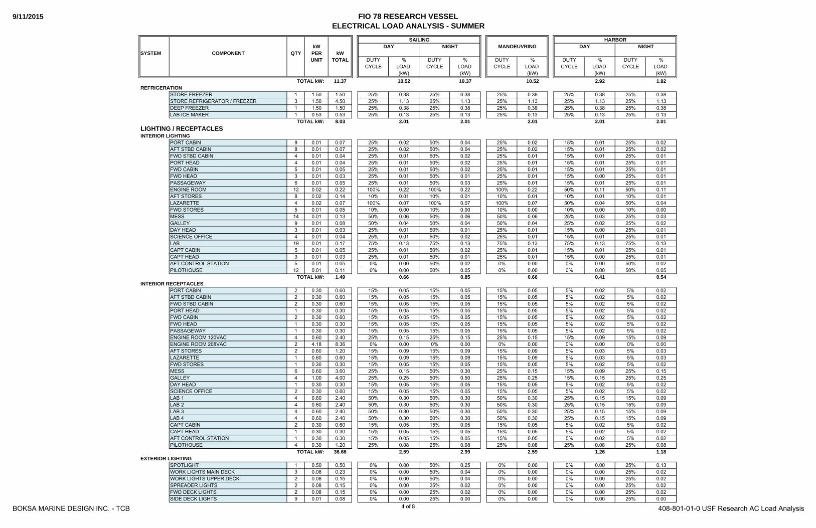
9/11/2015 FIO 78 RESEARCH VESSELELECTRICAL LOAD ANALYSIS - SUMMER
kWSYSTEM COMPONENT QTY PER kW
UNIT TOTAL DUTY % DUTY % DUTY % DUTY % DUTY %CYCLE LOAD CYCLE LOAD CYCLE LOAD CYCLE LOAD CYCLE LOAD
(kW) (kW) (kW) (kW) (kW)
MANOEUVRING
TOTAL kW:
DAYSAILING
NIGHTHARBOR
DAY NIGHT
11.37 10.52 10.37 10.52 2.92 1.92
STORE FREEZER 1 1.50 1.50 25% 0.38 25% 0.38 25% 0.38 25% 0.38 25% 0.38STORE REFRIGERATOR / FREEZER 3 1.50 4.50 25% 1.13 25% 1.13 25% 1.13 25% 1.13 25% 1.13DEEP FREEZER 1 1.50 1.50 25% 0.38 25% 0.38 25% 0.38 25% 0.38 25% 0.38LAB ICE MAKER 1 0.53 0.53 25% 0.13 25% 0.13 25% 0.13 25% 0.13 25% 0.13
8.03 2.01 2.01 2.01 2.01 2.01
PORT CABIN 8 0.01 0.07 25% 0.02 50% 0.04 25% 0.02 15% 0.01 25% 0.02AFT STBD CABIN 8 0.01 0.07 25% 0.02 50% 0.04 25% 0.02 15% 0.01 25% 0.02FWD STBD CABIN 4 0.01 0.04 25% 0.01 50% 0.02 25% 0.01 15% 0.01 25% 0.01PORT HEAD 4 0.01 0.04 25% 0.01 50% 0.02 25% 0.01 15% 0.01 25% 0.01FWD CABIN 5 0.01 0.05 25% 0.01 50% 0.02 25% 0.01 15% 0.01 25% 0.01FWD HEAD 3 0.01 0.03 25% 0.01 50% 0.01 25% 0.01 15% 0.00 25% 0.01PASSAGEWAY 6 0.01 0.05 25% 0.01 50% 0.03 25% 0.01 15% 0.01 25% 0.01ENGINE ROOM 12 0.02 0.22 100% 0.22 100% 0.22 100% 0.22 50% 0.11 50% 0.11AFT STORES 8 0.02 0.14 10% 0.01 10% 0.01 10% 0.01 10% 0.01 10% 0.01LAZARETTE 4 0.02 0.07 100% 0.07 100% 0.07 100% 0.07 50% 0.04 50% 0.04FWD STORES 5 0.01 0.05 10% 0.00 10% 0.00 10% 0.00 10% 0.00 10% 0.00MESS 14 0.01 0.13 50% 0.06 50% 0.06 50% 0.06 25% 0.03 25% 0.03GALLEY 9 0.01 0.08 50% 0.04 50% 0.04 50% 0.04 25% 0.02 25% 0.02DAY HEAD 3 0.01 0.03 25% 0.01 50% 0.01 25% 0.01 15% 0.00 25% 0.01SCIENCE OFFICE 4 0.01 0.04 25% 0.01 50% 0.02 25% 0.01 15% 0.01 25% 0.01LAB 19 0.01 0.17 75% 0.13 75% 0.13 75% 0.13 75% 0.13 75% 0.13CAPT CABIN 5 0.01 0.05 25% 0.01 50% 0.02 25% 0.01 15% 0.01 25% 0.01CAPT HEAD 3 0.01 0.03 25% 0.01 50% 0.01 25% 0.01 15% 0.00 25% 0.01AFT CONTROL STATION 5 0.01 0.05 0% 0.00 50% 0.02 0% 0.00 0% 0.00 50% 0.02PILOTHOUSE 12 0.01 0.11 0% 0.00 50% 0.05 0% 0.00 0% 0.00 50% 0.05
1.49 0.66 0.85 0.66 0.41 0.54
PORT CABIN 2 0.30 0.60 15% 0.05 15% 0.05 15% 0.05 5% 0.02 5% 0.02AFT STBD CABIN 2 0.30 0.60 15% 0.05 15% 0.05 15% 0.05 5% 0.02 5% 0.02FWD STBD CABIN 2 0.30 0.60 15% 0.05 15% 0.05 15% 0.05 5% 0.02 5% 0.02PORT HEAD 1 0.30 0.30 15% 0.05 15% 0.05 15% 0.05 5% 0.02 5% 0.02FWD CABIN 2 0.30 0.60 15% 0.05 15% 0.05 15% 0.05 5% 0.02 5% 0.02FWD HEAD 1 0.30 0.30 15% 0.05 15% 0.05 15% 0.05 5% 0.02 5% 0.02PASSAGEWAY 1 0.30 0.30 15% 0.05 15% 0.05 15% 0.05 5% 0.02 5% 0.02ENGINE ROOM 120VAC 4 0.60 2.40 25% 0.15 25% 0.15 25% 0.15 15% 0.09 15% 0.09ENGINE ROOM 208VAC 2 4.18 8.36 0% 0.00 0% 0.00 0% 0.00 0% 0.00 0% 0.00AFT STORES 2 0.60 1.20 15% 0.09 15% 0.09 15% 0.09 5% 0.03 5% 0.03LAZARETTE 1 0.60 0.60 15% 0.09 15% 0.09 15% 0.09 5% 0.03 5% 0.03FWD STORES 1 0.30 0.30 15% 0.05 15% 0.05 15% 0.05 5% 0.02 5% 0.02MESS 6 0.60 3.60 25% 0.15 50% 0.30 25% 0.15 15% 0.09 25% 0.15GALLEY 4 1.00 4.00 25% 0.25 50% 0.50 25% 0.25 15% 0.15 25% 0.25DAY HEAD 1 0.30 0.30 15% 0.05 15% 0.05 15% 0.05 5% 0.02 5% 0.02SCIENCE OFFICE 2 0.30 0.60 15% 0.05 15% 0.05 15% 0.05 5% 0.02 5% 0.02LAB 1 4 0.60 2.40 50% 0.30 50% 0.30 50% 0.30 25% 0.15 15% 0.09LAB 2 4 0.60 2.40 50% 0.30 50% 0.30 50% 0.30 25% 0.15 15% 0.09LAB 3 4 0.60 2.40 50% 0.30 50% 0.30 50% 0.30 25% 0.15 15% 0.09LAB 4 4 0.60 2.40 50% 0.30 50% 0.30 50% 0.30 25% 0.15 15% 0.09CAPT CABIN 2 0.30 0.60 15% 0.05 15% 0.05 15% 0.05 5% 0.02 5% 0.02CAPT HEAD 1 0.30 0.30 15% 0.05 15% 0.05 15% 0.05 5% 0.02 5% 0.02AFT CONTROL STATION 1 0.30 0.30 15% 0.05 15% 0.05 15% 0.05 5% 0.02 5% 0.02PILOTHOUSE 4 0.30 1.20 25% 0.08 25% 0.08 25% 0.08 25% 0.08 25% 0.08
36.66 2.59 2.99 2.59 1.26 1.18
SPOTLIGHT 1 0.50 0.50 0% 0.00 50% 0.25 0% 0.00 0% 0.00 25% 0.13WORK LIGHTS MAIN DECK 3 0.08 0.23 0% 0.00 50% 0.04 0% 0.00 0% 0.00 25% 0.02WORK LIGHTS UPPER DECK 2 0.08 0.15 0% 0.00 50% 0.04 0% 0.00 0% 0.00 25% 0.02SPREADER LIGHTS 2 0.08 0.15 0% 0.00 25% 0.02 0% 0.00 0% 0.00 25% 0.02FWD DECK LIGHTS 2 0.08 0.15 0% 0.00 25% 0.02 0% 0.00 0% 0.00 25% 0.02SIDE DECK LIGHTS 9 0.01 0.08 0% 0.00 25% 0.00 0% 0.00 0% 0.00 25% 0.00
LIGHTING / RECEPTACLESINTERIOR LIGHTING
TOTAL kW:INTERIOR RECEPTACLES
TOTAL kW:EXTERIOR LIGHTING
TOTAL kW:REFRIGERATION
TOTAL kW:
BOKSA MARINE DESIGN INC. - TCB 408-801-01-0 USF Research AC Load Analysis4 of 8
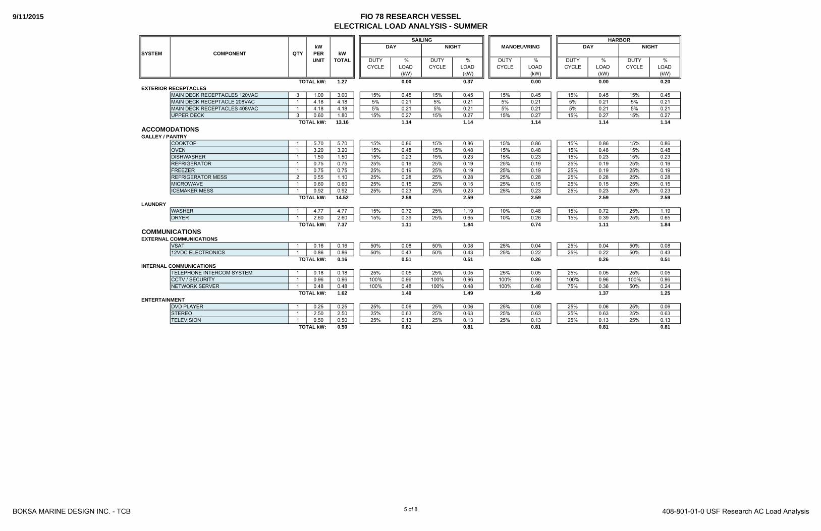
9/11/2015 FIO 78 RESEARCH VESSELELECTRICAL LOAD ANALYSIS - SUMMER
kWSYSTEM COMPONENT QTY PER kW
UNIT TOTAL DUTY % DUTY % DUTY % DUTY % DUTY %CYCLE LOAD CYCLE LOAD CYCLE LOAD CYCLE LOAD CYCLE LOAD
(kW) (kW) (kW) (kW) (kW)
MANOEUVRING
TOTAL kW:
DAYSAILING
NIGHTHARBOR
DAY NIGHT
1.27 0.00 0.37 0.00 0.00 0.20
MAIN DECK RECEPTACLES 120VAC 3 1.00 3.00 15% 0.45 15% 0.45 15% 0.45 15% 0.45 15% 0.45MAIN DECK RECEPTACLE 208VAC 1 4.18 4.18 5% 0.21 5% 0.21 5% 0.21 5% 0.21 5% 0.21MAIN DECK RECEPTACLES 408VAC 1 4.18 4.18 5% 0.21 5% 0.21 5% 0.21 5% 0.21 5% 0.21UPPER DECK 3 0.60 1.80 15% 0.27 15% 0.27 15% 0.27 15% 0.27 15% 0.27
13.16 1.14 1.14 1.14 1.14 1.14
COOKTOP 1 5.70 5.70 15% 0.86 15% 0.86 15% 0.86 15% 0.86 15% 0.86OVEN 1 3.20 3.20 15% 0.48 15% 0.48 15% 0.48 15% 0.48 15% 0.48DISHWASHER 1 1.50 1.50 15% 0.23 15% 0.23 15% 0.23 15% 0.23 15% 0.23REFRIGERATOR 1 0.75 0.75 25% 0.19 25% 0.19 25% 0.19 25% 0.19 25% 0.19FREEZER 1 0.75 0.75 25% 0.19 25% 0.19 25% 0.19 25% 0.19 25% 0.19REFRIGERATOR MESS 2 0.55 1.10 25% 0.28 25% 0.28 25% 0.28 25% 0.28 25% 0.28MICROWAVE 1 0.60 0.60 25% 0.15 25% 0.15 25% 0.15 25% 0.15 25% 0.15ICEMAKER MESS 1 0.92 0.92 25% 0.23 25% 0.23 25% 0.23 25% 0.23 25% 0.23
14.52 2.59 2.59 2.59 2.59 2.59
WASHER 1 4.77 4.77 15% 0.72 25% 1.19 10% 0.48 15% 0.72 25% 1.19DRYER 1 2.60 2.60 15% 0.39 25% 0.65 10% 0.26 15% 0.39 25% 0.65
7.37 1.11 1.84 0.74 1.11 1.84
VSAT 1 0.16 0.16 50% 0.08 50% 0.08 25% 0.04 25% 0.04 50% 0.0812VDC ELECTRONICS 1 0.86 0.86 50% 0.43 50% 0.43 25% 0.22 25% 0.22 50% 0.43
0.16 0.51 0.51 0.26 0.26 0.51
TELEPHONE INTERCOM SYSTEM 1 0.18 0.18 25% 0.05 25% 0.05 25% 0.05 25% 0.05 25% 0.05CCTV / SECURITY 1 0.96 0.96 100% 0.96 100% 0.96 100% 0.96 100% 0.96 100% 0.96NETWORK SERVER 1 0.48 0.48 100% 0.48 100% 0.48 100% 0.48 75% 0.36 50% 0.24
1.62 1.49 1.49 1.49 1.37 1.25
DVD PLAYER 1 0.25 0.25 25% 0.06 25% 0.06 25% 0.06 25% 0.06 25% 0.06STEREO 1 2.50 2.50 25% 0.63 25% 0.63 25% 0.63 25% 0.63 25% 0.63TELEVISION 1 0.50 0.50 25% 0.13 25% 0.13 25% 0.13 25% 0.13 25% 0.13
0.50 0.81 0.81 0.81 0.81 0.81
TOTAL kW:COMMUNICATIONSEXTERNAL COMMUNICATIONS
TOTAL kW:
TOTAL kW:EXTERIOR RECEPTACLES
ACCOMODATIONSTOTAL kW:
GALLEY / PANTRY
TOTAL kW:LAUNDRY
TOTAL kW:
INTERNAL COMMUNICATIONS
TOTAL kW:ENTERTAINMENT
BOKSA MARINE DESIGN INC. - TCB 408-801-01-0 USF Research AC Load Analysis5 of 8

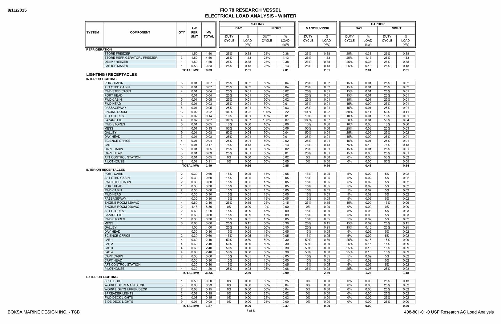
9/11/2015 FIO 78 RESEARCH VESSELELECTRICAL LOAD ANALYSIS - WINTER
kWSYSTEM COMPONENT QTY PER kW
UNIT TOTAL DUTY % DUTY % DUTY % DUTY % DUTY %CYCLE LOAD CYCLE LOAD CYCLE LOAD CYCLE LOAD CYCLE LOAD
(kW) (kW) (kW) (kW) (kW)203.59 52.61 49.76 51.51 34.72 30.49
1.80BATTERY CHARGER ENGINE 1 0.96 0.96 10% 0.10 10% 0.10 10% 0.10 15% 0.14 15% 0.14BATTERY CHARGER GENERATORS 1 0.96 0.96 10% 0.10 10% 0.10 10% 0.10 15% 0.14 15% 0.14BATTERY CHARGER SHIPS SERVICE 1 1.44 1.44 10% 0.14 10% 0.14 10% 0.14 15% 0.22 15% 0.22BATTERY CHARGER GMDSS 1 0.96 0.96 5% 0.05 5% 0.05 5% 0.05 15% 0.14 15% 0.14BATTERY CHARGER EMERGENCY SERVICE 1 0.96 0.96 5% 0.05 5% 0.05 5% 0.05 15% 0.14 15% 0.14
5.28 0.43 0.43 0.43 0.79 0.79
FUEL TRANSFER 2 4.81 9.62 15% 1.44 15% 1.44 10% 0.96 15% 1.44 15% 1.449.62 1.44 1.44 0.96 1.44 1.44
FRESH WATER MAKER 1 0.86 0.86 50% 0.43 50% 0.43 50% 0.43 - - - -FRESH WATER MAKER FEED PUMP 1 1.33 1.33 50% 0.67 50% 0.67 50% 0.67 - - - -FRESH WATER PRESSURE PUMP 2 3.71 7.42 25% 1.86 35% 2.60 25% 1.86 25% 1.86 25% 1.86WATER HEATER 1 4.50 4.50 15% 0.68 25% 1.13 15% 0.68 15% 0.68 25% 1.13
14.11 3.63 4.82 3.63 2.53 2.98
RAW WATER PUMP 2 0.86 1.73 15% 0.26 10% 0.17 15% 0.26 15% 0.26 10% 0.17BALLAST PUMP 2 1.90 3.80 10% 0.38 10% 0.38 10% 0.38 10% 0.38 10% 0.38FLOW THRU PUMP 1 1.83 1.83 25% 0.46 25% 0.46 25% 0.46 - - - -
7.36 1.10 1.01 1.10 0.64 0.55
AIR COMPRESSOR 1 13.31 13.31 10% 1.33 10% 1.33 10% 1.33 10% 1.33 10% 1.33DIVE COMPRESSOR 1 3.06 3.06 5% 0.15 5% 0.15 5% 0.15 5% 0.15 5% 0.15VACUUM PUMP 1 1.65 1.65 25% 0.41 25% 0.41 25% 0.41 25% 0.41 25% 0.41
18.02 1.90 1.90 1.90 1.90 1.90
SEWAGE TREATMENT PLANT 1 5.67 5.67 50% 2.84 50% 2.84 50% 2.84 25% 1.42 25% 1.42LIFT PUMP 1 0.38 0.38 25% 0.10 25% 0.10 25% 0.10 25% 0.10 25% 0.10TRANSFER PUMP 1 0.58 0.58 25% 0.14 25% 0.14 25% 0.14 25% 0.14 25% 0.14GREY WATER LIFT PUMP 1 0.58 0.58 15% 0.09 15% 0.09 15% 0.09 15% 0.09 15% 0.09
7.21 3.16 3.16 3.16 1.74 1.74BILGE SYSTEM
BILGE / FIRE PUMP 2 13.32 26.63 5% 1.33 5% 1.33 5% 1.33 5% 1.33 5% 1.3326.63 1.33 1.33 1.33 1.33 1.33
CHILLED WATER UNITS 2 8.44 16.88 75% 12.66 50% 8.44 75% 12.66 50% 8.44 25% 4.22CHILLED WATER UNIT SEA WATER PUMP 1 0.36 0.36 100% 0.36 50% 0.18 100% 0.36 50% 0.18 25% 0.09CHILLED WATER CIRCULATING PUMP 1 1.36 1.36 100% 1.36 50% 0.68 100% 1.36 50% 0.68 25% 0.34AIR HANDLER FWD CABIN 1 0.13 0.13 50% 0.06 50% 0.06 50% 0.06 25% 0.03 25% 0.03AIR HANDLER FWD HEAD 1 0.17 0.17 50% 0.09 50% 0.09 50% 0.09 25% 0.04 25% 0.04AIR HANDLER FWD STBD CABIN 1 0.17 0.17 50% 0.09 50% 0.09 50% 0.09 25% 0.04 25% 0.04AIR HANDLER AFT STBD CABIN 1 0.13 0.13 50% 0.06 50% 0.06 50% 0.06 25% 0.03 25% 0.03AIR HANDLER PORT HEAD 1 0.17 0.17 50% 0.09 50% 0.09 50% 0.09 25% 0.04 25% 0.04AIR HANDLER PORT CABIN 1 0.13 0.13 50% 0.06 50% 0.06 50% 0.06 25% 0.03 25% 0.03AIR HANDLER MESS 1 0.25 0.25 75% 0.18 50% 0.12 75% 0.18 50% 0.12 25% 0.06AIR HANDLER GALLEY 1 0.16 0.16 75% 0.12 50% 0.08 75% 0.12 50% 0.08 50% 0.08AIR HANDLER OFFICE 1 0.13 0.13 75% 0.10 50% 0.06 75% 0.10 50% 0.06 50% 0.06AIR HANDLER LAB 2 0.25 0.49 75% 0.37 50% 0.25 75% 0.37 50% 0.25 50% 0.25AIR HANDLER PILOTHOUSE 2 0.34 0.68 75% 0.51 50% 0.34 75% 0.51 50% 0.34 50% 0.34
21.21 16.11 10.61 16.11 10.38 5.67
ENGINE ROOM INTAKE FAN 1 6.97 6.97 100% 6.97 100% 6.97 100% 6.97 25% 1.74 15% 1.05ENGINE ROOM EXHAUST FAN 1 3.05 3.05 100% 3.05 100% 3.05 100% 3.05 25% 0.76 15% 0.46GALLEY EXHAUST FAN 1 0.32 0.32 15% 0.05 15% 0.05 15% 0.05 5% 0.02 5% 0.02LAB VENT HOOD 1 0.53 0.53 15% 0.08 15% 0.08 15% 0.08 5% 0.03 5% 0.03FORWARD STORES VENTILATION 1 0.20 0.20 75% 0.15 75% 0.15 75% 0.15 75% 0.15 75% 0.15AFT STORES VENTILATION 1 0.30 0.30 75% 0.23 25% 0.08 75% 0.23 75% 0.23 75% 0.23
11.37 10.52 10.37 10.52 2.92 1.92
TOTAL kW:
DAY NIGHT
PROPULSION
FRESH WATER SYSTEM
TOTAL kW:
MACHINERY
FUEL SYSTEM
TOTAL kW:
ELECTRIC
TOTAL kW:
RAW WATER SYSTEM
HARBORDAY NIGHT MANOEUVRING
TOTAL kW:
SAILING
COMPRESSED AIR SERVICE
TOTAL kW:
HVAC / VENTILATIONAIR CONDITIONING
TOTAL kW:VENTILATION
TOTAL kW:
BLACK / GREY WATER SYSTEM
TOTAL kW:
TOTAL kW:
BOKSA MARINE DESIGN INC. - TCB 408-801-01-0 USF Research AC Load Analysis6 of 8
9/11/2015 FIO 78 RESEARCH VESSELELECTRICAL LOAD ANALYSIS - WINTER
kWSYSTEM COMPONENT QTY PER kW
UNIT TOTAL DUTY % DUTY % DUTY % DUTY % DUTY %CYCLE LOAD CYCLE LOAD CYCLE LOAD CYCLE LOAD CYCLE LOAD
(kW) (kW) (kW) (kW) (kW)
DAY NIGHTHARBOR
DAY NIGHT MANOEUVRING
TOTAL kW:
SAILING
STORE FREEZER 1 1.50 1.50 25% 0.38 25% 0.38 25% 0.38 25% 0.38 25% 0.38STORE REFRIGERATOR / FREEZER 3 1.50 4.50 25% 1.13 25% 1.13 25% 1.13 25% 1.13 25% 1.13DEEP FREEZER 1 1.50 1.50 25% 0.38 25% 0.38 25% 0.38 25% 0.38 25% 0.38LAB ICE MAKER 1 0.53 0.53 25% 0.13 25% 0.13 25% 0.13 25% 0.13 25% 0.13
8.03 2.01 2.01 2.01 2.01 2.01
PORT CABIN 8 0.01 0.07 25% 0.02 50% 0.04 25% 0.02 15% 0.01 25% 0.02AFT STBD CABIN 8 0.01 0.07 25% 0.02 50% 0.04 25% 0.02 15% 0.01 25% 0.02FWD STBD CABIN 4 0.01 0.04 25% 0.01 50% 0.02 25% 0.01 15% 0.01 25% 0.01PORT HEAD 4 0.01 0.04 25% 0.01 50% 0.02 25% 0.01 15% 0.01 25% 0.01FWD CABIN 5 0.01 0.05 25% 0.01 50% 0.02 25% 0.01 15% 0.01 25% 0.01FWD HEAD 3 0.01 0.03 25% 0.01 50% 0.01 25% 0.01 15% 0.00 25% 0.01PASSAGEWAY 6 0.01 0.05 25% 0.01 50% 0.03 25% 0.01 15% 0.01 25% 0.01ENGINE ROOM 12 0.02 0.22 100% 0.22 100% 0.22 100% 0.22 50% 0.11 50% 0.11AFT STORES 8 0.02 0.14 10% 0.01 10% 0.01 10% 0.01 10% 0.01 10% 0.01LAZARETTE 4 0.02 0.07 100% 0.07 100% 0.07 100% 0.07 50% 0.04 50% 0.04FWD STORES 5 0.01 0.05 10% 0.00 10% 0.00 10% 0.00 10% 0.00 10% 0.00MESS 14 0.01 0.13 50% 0.06 50% 0.06 50% 0.06 25% 0.03 25% 0.03GALLEY 9 0.01 0.08 50% 0.04 50% 0.04 50% 0.04 25% 0.02 25% 0.02DAY HEAD 3 0.01 0.03 25% 0.01 50% 0.01 25% 0.01 15% 0.00 25% 0.01SCIENCE OFFICE 4 0.01 0.04 25% 0.01 50% 0.02 25% 0.01 15% 0.01 25% 0.01LAB 19 0.01 0.17 75% 0.13 75% 0.13 75% 0.13 75% 0.13 75% 0.13CAPT CABIN 5 0.01 0.05 25% 0.01 50% 0.02 25% 0.01 15% 0.01 25% 0.01CAPT HEAD 3 0.01 0.03 25% 0.01 50% 0.01 25% 0.01 15% 0.00 25% 0.01AFT CONTROL STATION 5 0.01 0.05 0% 0.00 50% 0.02 0% 0.00 0% 0.00 50% 0.02PILOTHOUSE 12 0.01 0.11 0% 0.00 50% 0.05 0% 0.00 0% 0.00 50% 0.05
1.49 0.66 0.85 0.66 0.41 0.54
PORT CABIN 2 0.30 0.60 15% 0.05 15% 0.05 15% 0.05 5% 0.02 5% 0.02AFT STBD CABIN 2 0.30 0.60 15% 0.05 15% 0.05 15% 0.05 5% 0.02 5% 0.02FWD STBD CABIN 2 0.30 0.60 15% 0.05 15% 0.05 15% 0.05 5% 0.02 5% 0.02PORT HEAD 1 0.30 0.30 15% 0.05 15% 0.05 15% 0.05 5% 0.02 5% 0.02FWD CABIN 2 0.30 0.60 15% 0.05 15% 0.05 15% 0.05 5% 0.02 5% 0.02FWD HEAD 1 0.30 0.30 15% 0.05 15% 0.05 15% 0.05 5% 0.02 5% 0.02PASSAGEWAY 1 0.30 0.30 15% 0.05 15% 0.05 15% 0.05 5% 0.02 5% 0.02ENGINE ROOM 120VAC 4 0.60 2.40 25% 0.15 25% 0.15 25% 0.15 15% 0.09 15% 0.09ENGINE ROOM 208VAC 2 4.18 8.36 0% 0.00 0% 0.00 0% 0.00 0% 0.00 0% 0.00AFT STORES 2 0.60 1.20 15% 0.09 15% 0.09 15% 0.09 5% 0.03 5% 0.03LAZARETTE 1 0.60 0.60 15% 0.09 15% 0.09 15% 0.09 5% 0.03 5% 0.03FWD STORES 1 0.30 0.30 15% 0.05 15% 0.05 15% 0.05 5% 0.02 5% 0.02MESS 6 0.60 3.60 25% 0.15 50% 0.30 25% 0.15 15% 0.09 25% 0.15GALLEY 4 1.00 4.00 25% 0.25 50% 0.50 25% 0.25 15% 0.15 25% 0.25DAY HEAD 1 0.30 0.30 15% 0.05 15% 0.05 15% 0.05 5% 0.02 5% 0.02SCIENCE OFFICE 2 0.30 0.60 15% 0.05 15% 0.05 15% 0.05 5% 0.02 5% 0.02LAB 1 4 0.60 2.40 50% 0.30 50% 0.30 50% 0.30 25% 0.15 15% 0.09LAB 2 4 0.60 2.40 50% 0.30 50% 0.30 50% 0.30 25% 0.15 15% 0.09LAB 3 4 0.60 2.40 50% 0.30 50% 0.30 50% 0.30 25% 0.15 15% 0.09LAB 4 4 0.60 2.40 50% 0.30 50% 0.30 50% 0.30 25% 0.15 15% 0.09CAPT CABIN 2 0.30 0.60 15% 0.05 15% 0.05 15% 0.05 5% 0.02 5% 0.02CAPT HEAD 1 0.30 0.30 15% 0.05 15% 0.05 15% 0.05 5% 0.02 5% 0.02AFT CONTROL STATION 1 0.30 0.30 15% 0.05 15% 0.05 15% 0.05 5% 0.02 5% 0.02PILOTHOUSE 4 0.30 1.20 25% 0.08 25% 0.08 25% 0.08 25% 0.08 25% 0.08
36.66 2.59 2.99 2.59 1.26 1.18
SPOTLIGHT 1 0.50 0.50 0% 0.00 50% 0.25 0% 0.00 0% 0.00 25% 0.13WORK LIGHTS MAIN DECK 3 0.08 0.23 0% 0.00 50% 0.04 0% 0.00 0% 0.00 25% 0.02WORK LIGHTS UPPER DECK 2 0.08 0.15 0% 0.00 50% 0.04 0% 0.00 0% 0.00 25% 0.02SPREADER LIGHTS 2 0.08 0.15 0% 0.00 25% 0.02 0% 0.00 0% 0.00 25% 0.02FWD DECK LIGHTS 2 0.08 0.15 0% 0.00 25% 0.02 0% 0.00 0% 0.00 25% 0.02SIDE DECK LIGHTS 9 0.01 0.08 0% 0.00 25% 0.00 0% 0.00 0% 0.00 25% 0.00
1.27 0.00 0.37 0.00 0.00 0.20
REFRIGERATION
TOTAL kW:LIGHTING / RECEPTACLESINTERIOR LIGHTING
TOTAL kW:INTERIOR RECEPTACLES
TOTAL kW:EXTERIOR LIGHTING
TOTAL kW:
BOKSA MARINE DESIGN INC. - TCB 408-801-01-0 USF Research AC Load Analysis7 of 8

9/11/2015 FIO 78 RESEARCH VESSELELECTRICAL LOAD ANALYSIS - WINTER
kWSYSTEM COMPONENT QTY PER kW
UNIT TOTAL DUTY % DUTY % DUTY % DUTY % DUTY %CYCLE LOAD CYCLE LOAD CYCLE LOAD CYCLE LOAD CYCLE LOAD
(kW) (kW) (kW) (kW) (kW)
DAY NIGHTHARBOR
DAY NIGHT MANOEUVRING
TOTAL kW:
SAILING
MAIN DECK RECEPTACLES 120VAC 3 1.00 3.00 15% 0.45 15% 0.45 15% 0.45 15% 0.45 15% 0.45MAIN DECK RECEPTACLE 208VAC 1 4.18 4.18 5% 0.21 5% 0.21 5% 0.21 5% 0.21 5% 0.21MAIN DECK RECEPTACLES 408VAC 1 4.18 4.18 5% 0.21 5% 0.21 5% 0.21 5% 0.21 5% 0.21UPPER DECK 3 0.60 1.80 15% 0.27 15% 0.27 15% 0.27 15% 0.27 15% 0.27
13.16 1.14 1.14 1.14 1.14 1.14
COOKTOP 1 2.30 2.30 25% 0.58 25% 0.58 25% 0.58 25% 0.58 25% 0.58OVEN 1 2.80 2.80 25% 0.70 25% 0.70 25% 0.70 25% 0.70 25% 0.70DISHWASHER 1 1.50 1.50 25% 0.38 25% 0.38 25% 0.38 25% 0.38 25% 0.38REFRIGERATOR 1 0.75 0.75 25% 0.19 25% 0.19 25% 0.19 25% 0.19 25% 0.19FREEZER 1 0.75 0.75 25% 0.19 25% 0.19 25% 0.19 25% 0.19 25% 0.19REFRIGERATOR MESS 2 0.55 1.10 25% 0.28 25% 0.28 25% 0.28 25% 0.28 25% 0.28MICROWAVE 1 0.60 0.60 25% 0.15 25% 0.15 25% 0.15 25% 0.15 25% 0.15ICEMAKER MESS 1 0.92 0.92 25% 0.23 25% 0.23 25% 0.23 25% 0.23 25% 0.23
10.72 2.68 2.68 2.68 2.68 2.68
WASHER 1 4.77 4.77 15% 0.72 25% 1.19 10% 0.48 15% 0.72 25% 1.19DRYER 1 2.60 2.60 15% 0.39 25% 0.65 10% 0.26 15% 0.39 25% 0.65
7.37 1.11 1.84 0.74 1.11 1.84
VSAT 1 0.16 0.16 50% 0.08 50% 0.08 25% 0.04 25% 0.04 50% 0.0812VDC ELECTRONICS 1 0.86 0.86 50% 0.43 50% 0.43 25% 0.22 25% 0.22 50% 0.43
0.16 0.51 0.51 0.26 0.26 0.51
TELEPHONE INTERCOM SYSTEM 1 0.18 0.18 25% 0.05 25% 0.05 25% 0.05 25% 0.05 25% 0.05CCTV / SECURITY 1 0.96 0.96 100% 0.96 100% 0.96 100% 0.96 100% 0.96 100% 0.96NETWORK SERVER 1 0.48 0.48 100% 0.48 100% 0.48 100% 0.48 75% 0.36 50% 0.24
1.62 1.49 1.49 1.49 1.37 1.25
DVD PLAYER 1 0.25 0.25 25% 0.06 25% 0.06 25% 0.06 25% 0.06 25% 0.06STEREO 1 2.50 2.50 25% 0.63 25% 0.63 25% 0.63 25% 0.63 25% 0.63TELEVISION 1 0.50 0.50 25% 0.13 25% 0.13 25% 0.13 25% 0.13 25% 0.13
0.50 0.81 0.81 0.81 0.81 0.81
LAUNDRYTOTAL kW:
EXTERIOR RECEPTACLES
GALLEY / PANTRYACCOMODATIONS
TOTAL kW:
TOTAL kW:
ENTERTAINMENT
TOTAL kW:COMMUNICATIONSEXTERNAL COMMUNICATIONS
TOTAL kW:INTERNAL COMMUNICATIONS
TOTAL kW:
BOKSA MARINE DESIGN INC. - TCB 408-801-01-0 USF Research AC Load Analysis8 of 8
No.:
PROJECT CLIENT
REVISIONS:
REFERENCES:
No.: By: Date:0 JRK 10-Sep-15
DRAWN BY:
TCB
DATE:
14-May-15 DWG. #: SHEET: REV.: SCALE:
1 OF 7 0 NONE
15515 Starling Crossing Lithia,Floride 33547
(813) 654-9800www.boksamarinedesign.com
408-800-02
DC LOAD ANALYSIS
PROJECT
FIO
TITLE:
REVISIONS:
INITIAL RELEASE FOR REGULATORY REVIEW

FIO 78 RESEARCH VESSELDC LOAD ANALYSIS AND RESERVE CAPACITY CALCULATION
408-800-02-0 USF Research DC Load Analysis
SERVICE COMPONENT QTY PER AMP
UNIT TOTAL DUTY % DUTY % DUTY % DUTY %
CYCLE LOAD CYCLE LOAD CYCLE LOAD CYCLE LOAD
AMP AMP AMP AMP
FUEL LEVEL MONITOR 1 3.50 3.50 100% 3.50 100% 3.50 25% 0.88 25% 0.88
THRUSTER CONTROL 1 2.00 2.00 5% 0.10 5% 0.10 5% 0.10 5% 10.00
ANCHOR WINDLASS CONTROL 1 2.00 2.00 5% 0.10 5% 0.10 5% 0.10 5% 0.10
WINCH CONTROL 1 2.00 2.00 5% 0.10 5% 0.10 5% 0.10 5% 0.10
CRANE CONTROL 1 2.00 2.00 5% 0.10 5% 0.10 5% 0.10 5% 0.10
J FRAME CONTROL 1 2.00 2.00 5% 0.10 5% 0.10 5% 0.10 5% 0.10
A FRAME CONTROL 1 2.00 2.00 5% 0.10 5% 0.10 5% 0.10 5% 0.10
HOLDING TANK MONITOR 1 1.50 1.50 100% 1.50 100% 1.50 100% 1.50 100% 1.50
HEAD ADDER VALVES 4 0.38 1.52 15% 0.23 15% 0.23 15% 0.23 15% 0.23
BILGE PUMPS 6 6.00 36.00 5% 1.80 5% 1.80 5% 1.80 5% 1.80
FWD WIPERS 5 2.00 10.00 25% 2.50 25% 2.50 5% 0.50 5% 0.50
AFT CONTROL WIPERS 2 2.00 4.00 10% 0.40 10% 0.40 5% 0.20 5% 0.20
DOG HOUSE WIPER 1 2.00 2.00 10% 0.20 10% 0.20 10% 0.20 10% 0.20
WIPER WASH 3 0.25 0.75 5% 0.04 5% 0.04 5% 0.04 5% 0.04
AUTO PILOT HEAD 1 2.00 2.00 100% 2.00 100% 2.00 0% 0.00 0% 0.00
AUTOPILOT PUMP 1 15.00 15.00 25% 3.75 25% 3.75 0% 0.00 0% 0.00
RADAR 1 4.97 4.97 100% 4.97 100% 4.97 15% 0.75 15% 0.75
WEATHERFAX 1 0.63 0.63 25% 0.16 25% 0.16 25% 0.16 25% 0.16
SONAR 1 4.58 4.58 50% 2.29 50% 2.29 15% 0.69 15% 0.69
VHF 1 4.70 4.70 25% 1.18 25% 1.18 25% 1.18 25% 1.18
12VDC ELECTRONICS 1 5.00 5.00 15% 0.75 15% 0.75 15% 0.75 15% 0.75
24VDC GMDSS SERVICE 1 48.72 48.72 FACTORED 18.80 FACTORED 18.80 FACTORED 0.81 FACTORED 20.30
24VDC EMERGENCY SERVICE 1 44.56 44.56 FACTORED 13.06 FACTORED 13.06 FACTORED 7.96 FACTORED 7.96
TOTAL CONNECTED LOAD : 201.43 TOTAL : 57.72 TOTAL : 57.72 TOTAL : 18.23 TOTAL : 47.62
RADAR 1 6.04 6.04 75% 4.53 75% 4.53 75% 4.53 75% 4.53
MULTIFUNCTION DISPLAYS 4 1.80 7.20 100% 7.20 100% 7.20 100% 7.20 100% 7.20
SATELLITE COMPASS 1 0.50 0.50 100% 0.50 100% 0.50 100% 0.50 100% 0.50
SOUNDER 1 1.40 1.40 100% 1.40 100% 1.40 100% 1.40 100% 1.40
12VDC ELECTRONICS 1 2.00 2.00 25% 0.50 25% 0.50 100% 2.00 100% 2.00
SSB 1 20.00 20.00 10% 2.00 10% 2.00 10% 2.00 10% 2.00
VHF 1 4.70 4.70 15% 0.71 15% 0.71 15% 0.71 15% 0.71
NAVTEX 1 0.10 0.10 100% 0.10 100% 0.10 100% 0.10 100% 0.10
PRINTER 1 0.36 0.36 15% 0.05 15% 0.05 15% 0.05 15% 0.05
AIS 1 1.00 1.00 100% 1.00 100% 1.00 100% 1.00 100% 1.00
INMARSAT 1 5.42 5.42 15% 0.81 15% 0.81 15% 0.81 15% 0.81
TOTAL CONNECTED LOAD : 48.72 TOTAL : 18.80 TOTAL : 18.80 TOTAL : 20.30 TOTAL : 20.30
24VDC EMERGENCY SERVICE FUEL ISOLATION VALVES 8 1.00 8.00 5% 0.40 5% 0.40 10% 0.80 10% 0.80
SHAFT SEAL PUMP 1 6.00 6.00 100% 6.00 100% 6.00 0% 0.00 0% 0.00
HORN COMPRESSOR 1 14.00 14.00 10% 1.40 10% 1.40 10% 1.40 10% 1.40
HORN CONTROLLER 1 2.00 2.00 10% 0.20 10% 0.20 10% 0.20 10% 0.20
NAVIGATION LIGHTS RUNNING 4 0.38 1.52 100% 1.52 100% 1.52 100% 1.52 100% 1.52
NAVIGATION LIGHTS TOW 4 0.38 1.52 100% 1.52 100% 1.52 100% 1.52 100% 1.52
NAVIGATION LIGHTS ANCHOR 1 0.38 0.38 100% 0.38 100% 0.38 100% 0.38 100% 0.38
NAVIGATION LIGHTS NUC 3 0.38 1.14 100% 1.14 100% 1.14 100% 1.14 100% 1.14
EMERGENCY LIGHTS 1 15.72 15.72 100% 15.72 100% 15.72 100% 15.72 100% 15.72
PA/GENERAL ALARM 1 5.00 5.00 5% 0.25 5% 0.25 5% 0.25 5% 0.25
FIRE ALARM 1 5.00 5.00 5% 0.25 5% 0.25 15% 0.75 15% 0.75
TOTAL CONNECTED LOAD : 60.28 TOTAL : 28.78 TOTAL : 28.78 TOTAL : 23.68 TOTAL : 23.68
24VDC GMDSS SERVICE
24VDC SHIPS SERVICE
AMP
SAILING HARBOR
DAY NIGHT DAY NIGHT
BOKSA NARINE DESIGN - TCB PAGE 2 OF 7

FIO 78 RESEARCH VESSELDC LOAD ANALYSIS AND RESERVE CAPACITY CALCULATION
408-800-02-0 USF Research DC Load Analysis
SERVICE COMPONENT QTY PER AMP
UNIT TOTAL DUTY % DUTY % DUTY % DUTY %
CYCLE LOAD CYCLE LOAD CYCLE LOAD CYCLE LOAD
AMP AMP AMP AMP
AMP
SAILING HARBOR
DAY NIGHT DAY NIGHT
24VDC EMERGENCY LIGHTINGSERVICE
PORT AFT CABIN 1 0.38 0.38 100% 0.38 100% 0.38 100% 0.38 100% 0.38
STBD AFT CABIN 1 0.38 0.38 100% 0.38 100% 0.38 100% 0.38 100% 0.38
STBD FWD CABIN 1 0.38 0.38 100% 0.38 100% 0.38 100% 0.38 100% 0.38
CREW CABIN 1 0.38 0.38 100% 0.38 100% 0.38 100% 0.38 100% 0.38
LOWER PASSAGEWAY 2 0.38 0.75 100% 0.75 100% 0.75 100% 0.75 100% 0.75
ENGINE ROOM 2 0.75 1.50 100% 1.50 100% 1.50 100% 1.50 100% 1.50
AFT STORES 1 0.75 0.75 100% 0.75 100% 0.75 100% 0.75 100% 0.75
LAZARETTE 1 0.75 0.75 100% 0.75 100% 0.75 100% 0.75 100% 0.75
FWD STORES 1 0.75 0.75 100% 0.75 100% 0.75 100% 0.75 100% 0.75
MESS 1 0.38 0.38 100% 0.38 100% 0.38 100% 0.38 100% 0.38
GALLEY 1 0.38 0.38 100% 0.38 100% 0.38 100% 0.38 100% 0.38
SCIENCE OFFICE 1 0.38 0.38 100% 0.38 100% 0.38 100% 0.38 100% 0.38
LAB 2 0.38 0.75 100% 0.75 100% 0.75 100% 0.75 100% 0.75
CAPTAINS CABIN 1 0.38 0.38 100% 0.38 100% 0.38 100% 0.38 100% 0.38
AFT CONTROL STATION 1 0.38 0.38 100% 0.38 100% 0.38 100% 0.38 100% 0.38
PILOTHOUSE 2 0.38 0.75 100% 0.75 100% 0.75 100% 0.75 100% 0.75
WORK LIGHTS MAIN DECK 1 3.17 3.17 100% 3.17 100% 3.17 100% 3.17 100% 3.17
WORK LIGHTS UPPER DECK 1 3.17 3.17 100% 3.17 100% 3.17 100% 3.17 100% 3.17
TOTAL CONNECTED LOAD : 15.72 TOTAL : 15.72 TOTAL : 15.72 TOTAL : 15.72 TOTAL : 15.72
BOKSA NARINE DESIGN - TCB PAGE 3 OF 7

FIO 78 RESEARCH VESSELDC LOAD ANALYSIS AND RESERVE CAPACITY
9/11/2015
4 255 510 255
57.72 4.4257.72 4.4218.23 13.9947.62 5.36
105 AMPS
54.97%54.97%
60 AMPS
30.38%79.36%
2 255 255 127.5
18.80 6.7818.80 6.7820.30 6.2820.30 6.28
40 AMPS
50.76%50.76%
HARBOR DAYHARBOR NIGHT
CHARGER - % OUTPUT REQUIRED TO MAINTAIN CHARGECHARGER OUTPUT :
CONDITION REQUIREDOUTPUT
SAILING NIGHTHARBOR DAYHARBOR NIGHT
HOURS AVAILABLE WITHOUT ALTERNATOR/CHARGER
CONDITIONFACTORED AMPS HOURS AVAILABLE
SAILING DAY
24VDC GMDSS SERVICE
8D BATTERIES IN SERIES / PARALLEL
BATTERYQUANTITY
AMP/HR EACHBATTERY
TOTAL AMP/HR /BANK TOTAL AMP/HR @
50%DOD
SAILING DAYSAILING NIGHT
HARBOR DAYHARBOR NIGHT
HARBOR DAY
CHARGER - % OUTPUT REQUIRED TO MAINTAIN CHARGECHARGER OUTPUT :
CONDITION REQUIREDOUTPUT
HARBOR NIGHT
BATTERYQUANTITY
AMP/HR EACHBATTERY
TOTAL AMP/HR /BANK TOTAL AMP/HR @
50%DOD
24VDC SHIP SERVICE
8D BATTERIES IN SERIES / PARALLEL
INCLUDING FACTORED 24VDC GMDSS AND EMERGENCY SERVICES
HOURS AVAILABLE WITHOUT ALTERNATOR/CHARGER
(1) ENGINE ALTERNATOR - % OUTPUT REQUIRED TO MAINTAIN CHARGE
CONDITION REQUIREDOUTPUT
ALTERNATOR OUTPUT :
FACTORED AMPS HOURS AVAILABLECONDITION
SAILING DAYSAILING NIGHT
BOKSA MARINE DESIGN - TCB PAGE 4 OF 7

FIO 78 RESEARCH VESSELDC LOAD ANALYSIS AND RESERVE CAPACITY
9/11/2015
2 255 255 127.5
28.78 4.4328.78 4.4323.68 5.3923.68 5.39
40 AMPS
59.19%59.19%
CONDITION REQUIREDOUTPUT
HARBOR DAYHARBOR NIGHT
SAILING NIGHTHARBOR DAYHARBOR NIGHT
CHARGER - % OUTPUT REQUIRED TO MAINTAIN CHARGECHARGER OUTPUT :
HOURS AVAILABLE WITHOUT ALTERNATOR/CHARGER
CONDITIONFACTORED AMPS HOURS AVAILABLE
SAILING DAY
24VDC EMERGENCY SERVICE
8D BATTERIES IN SERIES / PARALLEL
BATTERYQUANTITY
AMP/HR EACHBATTERY
TOTAL AMP/HR /BANK TOTAL AMP/HR @
50%DOD
INCLUDING 24VDC EMERGENCY LIGHTING SERVICE
BOKSA MARINE DESIGN - TCB PAGE 5 OF 7
FIO 78 RESEARCH VESSELDC LOAD ANALYSIS AND RESERVE CAPACITY
SERVICE COMPONENT QTY PER
UNIT
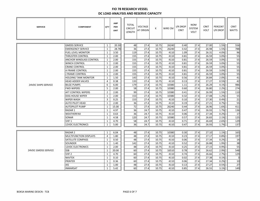
GMDSS SERVICE 1 20.30 48 27.4 10.75 26240 0.40 27.4 27.00 1.5% 556EMERGENCY SERVICE 1 28.78 36 27.4 10.75 26240 0.42 27.4 26.98 1.5% 788FUEL LEVEL MONITOR 1 3.50 119 27.4 10.75 4110 1.09 27.4 26.31 4.0% 96THRUSTER CONTROL 1 2.00 155 27.4 10.75 4110 0.81 27.4 26.59 3.0% 55ANCHOR WINDLASS CONTROL 1 2.00 155 27.4 10.75 4110 0.81 27.4 26.59 3.0% 55WINCH CONTROL 1 2.00 155 27.4 10.75 4110 0.81 27.4 26.59 3.0% 55CRANE CONTROL 1 2.00 155 27.4 10.75 4110 0.81 27.4 26.59 3.0% 55A FRAME CONTROL 1 2.00 155 27.4 10.75 4110 0.81 27.4 26.59 3.0% 55J FRAME CONTROL 1 2.00 155 27.4 10.75 4110 0.81 27.4 26.59 3.0% 55HOLDING TANK MONITOR 1 1.50 143 27.4 10.75 4110 0.56 27.4 26.84 2.0% 41HEAD ADDER VALVES 4 0.38 133 27.4 10.75 4110 0.13 27.4 27.27 0.5% 42BILGE PUMPS 6 6.00 179 27.4 10.75 10380 1.11 27.4 26.29 4.1% 986FWD WIPERS 5 2.00 58 27.4 10.75 10380 0.60 27.4 26.80 2.2% 274AFT CONTROL WIPERS 2 2.00 99 27.4 10.75 10380 0.41 27.4 26.99 1.5% 110DOG HOUSE WIPER 1 2.00 153 27.4 10.75 10380 0.32 27.4 27.08 1.2% 55WIPER WASH 3 0.25 153 27.4 10.75 4110 0.10 27.4 27.30 0.4% 21AUTO PILOT HEAD 1 2.00 36 27.4 10.75 4110 0.19 27.4 27.21 0.7% 55AUTOPILOT PUMP 1 15.00 72 27.4 10.75 26240 0.44 27.4 26.96 1.6% 411RADAR 1 1 4.97 36 24.7 10.75 4110 0.47 27.4 26.93 1.7% 136WEATHERFAX 1 0.63 36 24.7 10.75 4110 0.06 27.4 27.34 0.2% 17SONAR 1 4.58 120 24.7 10.75 10380 0.57 27.4 26.83 2.1% 125VHF 1 1 4.70 58 24.7 10.75 4110 0.71 27.4 26.69 2.6% 12912VDC ELECTRONICS 1 5.00 36 24.7 10.75 4110 0.47 27.4 26.93 1.7% 137
RADAR 2 1 6.04 48 27.4 10.75 10380 0.30 27.4 27.10 1.1% 165MULTIFUNCTION DISPLAYS 4 1.80 48 27.4 10.75 4110 0.23 27.4 27.17 0.8% 197SATELLITE COMPASS 1 0.50 48 27.4 10.75 4110 0.06 27.4 27.34 0.2% 14SOUNDER 1 1.40 142 27.4 10.75 4110 0.52 27.4 26.88 1.9% 3812VDC ELECTRONICS 1 2.00 48 27.4 10.75 4110 0.25 27.4 27.15 0.9% 55SSB 1 20.00 60 27.4 10.75 16510 0.78 27.4 26.62 2.9% 548VHF 2 1 4.70 60 27.4 10.75 4110 0.74 27.4 26.66 2.7% 129NAVTEX 1 0.10 60 27.4 10.75 4110 0.02 27.4 27.38 0.1% 3PRINTER 1 0.36 60 27.4 10.75 4110 0.06 27.4 27.34 0.2% 10AIS 1 1.00 48 27.4 10.75 4110 0.13 27.4 27.27 0.5% 27INMARSAT 1 5.42 60 27.4 10.75 4110 0.85 27.4 26.55 3.1% 149
AMP
CRKTWATTS
24VDC GMDSS SERVICE
24VDC SHIPS SERVICE
CRKTVOLT
PERCENTI/R DROP
TOTALCIRCUITLENGTH
VOLTAGEAT ORIGIN
K WIRE CMI/R DROP
CRKT
NOMSYSTEM
VOLT
BOKSA MARINE DESICN - TCB PAGE 6 OF 7
FIO 78 RESEARCH VESSELDC LOAD ANALYSIS AND RESERVE CAPACITY
SERVICE COMPONENT QTY PER
UNIT
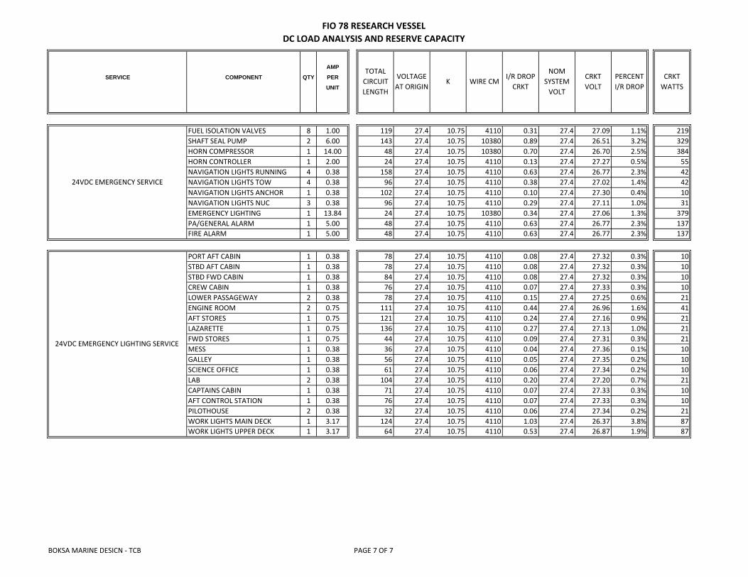
AMP
CRKTWATTS
CRKTVOLT
PERCENTI/R DROP
TOTALCIRCUITLENGTH
VOLTAGEAT ORIGIN
K WIRE CMI/R DROP
CRKT
NOMSYSTEM
VOLT
FUEL ISOLATION VALVES 8 1.00 119 27.4 10.75 4110 0.31 27.4 27.09 1.1% 219SHAFT SEAL PUMP 2 6.00 143 27.4 10.75 10380 0.89 27.4 26.51 3.2% 329HORN COMPRESSOR 1 14.00 48 27.4 10.75 10380 0.70 27.4 26.70 2.5% 384HORN CONTROLLER 1 2.00 24 27.4 10.75 4110 0.13 27.4 27.27 0.5% 55NAVIGATION LIGHTS RUNNING 4 0.38 158 27.4 10.75 4110 0.63 27.4 26.77 2.3% 42NAVIGATION LIGHTS TOW 4 0.38 96 27.4 10.75 4110 0.38 27.4 27.02 1.4% 42NAVIGATION LIGHTS ANCHOR 1 0.38 102 27.4 10.75 4110 0.10 27.4 27.30 0.4% 10NAVIGATION LIGHTS NUC 3 0.38 96 27.4 10.75 4110 0.29 27.4 27.11 1.0% 31EMERGENCY LIGHTING 1 13.84 24 27.4 10.75 10380 0.34 27.4 27.06 1.3% 379PA/GENERAL ALARM 1 5.00 48 27.4 10.75 4110 0.63 27.4 26.77 2.3% 137FIRE ALARM 1 5.00 48 27.4 10.75 4110 0.63 27.4 26.77 2.3% 137
PORT AFT CABIN 1 0.38 78 27.4 10.75 4110 0.08 27.4 27.32 0.3% 10STBD AFT CABIN 1 0.38 78 27.4 10.75 4110 0.08 27.4 27.32 0.3% 10STBD FWD CABIN 1 0.38 84 27.4 10.75 4110 0.08 27.4 27.32 0.3% 10CREW CABIN 1 0.38 76 27.4 10.75 4110 0.07 27.4 27.33 0.3% 10LOWER PASSAGEWAY 2 0.38 78 27.4 10.75 4110 0.15 27.4 27.25 0.6% 21ENGINE ROOM 2 0.75 111 27.4 10.75 4110 0.44 27.4 26.96 1.6% 41AFT STORES 1 0.75 121 27.4 10.75 4110 0.24 27.4 27.16 0.9% 21LAZARETTE 1 0.75 136 27.4 10.75 4110 0.27 27.4 27.13 1.0% 21FWD STORES 1 0.75 44 27.4 10.75 4110 0.09 27.4 27.31 0.3% 21MESS 1 0.38 36 27.4 10.75 4110 0.04 27.4 27.36 0.1% 10GALLEY 1 0.38 56 27.4 10.75 4110 0.05 27.4 27.35 0.2% 10SCIENCE OFFICE 1 0.38 61 27.4 10.75 4110 0.06 27.4 27.34 0.2% 10LAB 2 0.38 104 27.4 10.75 4110 0.20 27.4 27.20 0.7% 21CAPTAINS CABIN 1 0.38 71 27.4 10.75 4110 0.07 27.4 27.33 0.3% 10AFT CONTROL STATION 1 0.38 76 27.4 10.75 4110 0.07 27.4 27.33 0.3% 10PILOTHOUSE 2 0.38 32 27.4 10.75 4110 0.06 27.4 27.34 0.2% 21WORK LIGHTS MAIN DECK 1 3.17 124 27.4 10.75 4110 1.03 27.4 26.37 3.8% 87WORK LIGHTS UPPER DECK 1 3.17 64 27.4 10.75 4110 0.53 27.4 26.87 1.9% 87
24VDC EMERGENCY SERVICE
24VDC EMERGENCY LIGHTING SERVICE
BOKSA MARINE DESICN - TCB PAGE 7 OF 7
B
A
2 134
B
A
2 134
PROPRIETARY INFORMATION THIS DOCUMENT IS PROPRIETARY. NO DATA OR DESIGN SHALL BE COPIED, REPRODUCED, DISCLOSEDOR SUBMITTED TO ANY THIRD PARTY OR USED FOR CONSTRUCTION OR MANUFACTURE WHOLE OR IN PART, OF ANY PRODUCT DEFINEDWITHOUT PRIOR WRITTEN CONSENT OF BOKSA MARINE DESIGN, INC., TAMPA, FL 33547 - U.S.A.
BOKSA MARINE DESIGN, INC.Naval Architecture/Marine Engineering
15515 Starling Crossing Dr.Lithia, FL 33547(813) 654-9800
www.boksamarinedesign.com

Rev.: Date:Title:REFERENCES:
Drawing No.: Rev.: Date:
No.: By: Date:0 JRK 25-Nov-15
15515 Starling Crossing Dr.
Lithia, FL 33547
(813) 654-9800
DRAWN BY:
JRKDATE:
10-Feb-15FOR: DWG. #: SHEET: REV.: SCALE:
FIO 408-803-01 1 of 2 0 N/A
St. Petersburg, FL 33701
The Florida Institute ofOceanography
REVISIONS:
Initial Release
Title:Drawing No.:
727-553-1100
PROJECT:
78' RESEARCH VESSELTITLE:
DRAWING LIST
830 1st Street S.
The Florida Institute of Oceanography78' Research VesselRevision: 0Date: 25-Nov-15
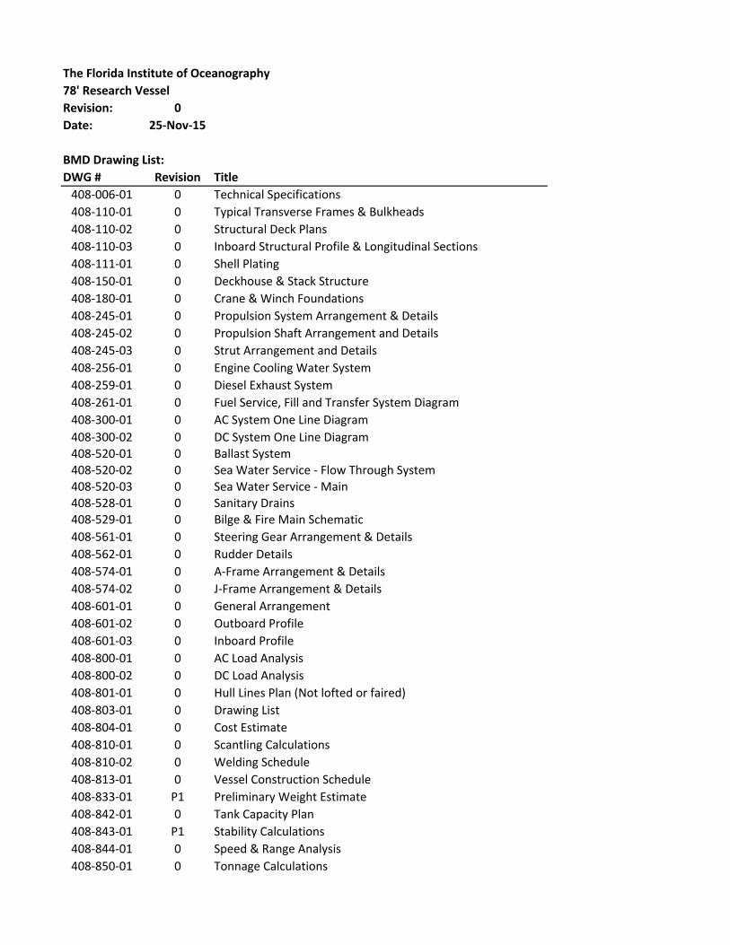
BMD Drawing List:DWG # Revision Title
408-006-01 0 Technical Specifications408-110-01 0 Typical Transverse Frames & Bulkheads408-110-02 0 Structural Deck Plans408-110-03 0 Inboard Structural Profile & Longitudinal Sections408-111-01 0 Shell Plating408-150-01 0 Deckhouse & Stack Structure408-180-01 0 Crane & Winch Foundations408-245-01 0 Propulsion System Arrangement & Details408-245-02 0 Propulsion Shaft Arrangement and Details408-245-03 0 Strut Arrangement and Details408-256-01 0 Engine Cooling Water System408-259-01 0 Diesel Exhaust System408-261-01 0 Fuel Service, Fill and Transfer System Diagram408-300-01 0 AC System One Line Diagram408-300-02 0 DC System One Line Diagram408-520-01 0 Ballast System408-520-02 0 Sea Water Service - Flow Through System408-520-03 0 Sea Water Service - Main408-528-01 0 Sanitary Drains408-529-01 0 Bilge & Fire Main Schematic408-561-01 0 Steering Gear Arrangement & Details408-562-01 0 Rudder Details408-574-01 0 A-Frame Arrangement & Details408-574-02 0 J-Frame Arrangement & Details408-601-01 0 General Arrangement408-601-02 0 Outboard Profile408-601-03 0 Inboard Profile408-800-01 0 AC Load Analysis408-800-02 0 DC Load Analysis408-801-01 0 Hull Lines Plan (Not lofted or faired)408-803-01 0 Drawing List408-804-01 0 Cost Estimate408-810-01 0 Scantling Calculations408-810-02 0 Welding Schedule408-813-01 0 Vessel Construction Schedule408-833-01 P1 Preliminary Weight Estimate408-842-01 0 Tank Capacity Plan408-843-01 P1 Stability Calculations408-844-01 0 Speed & Range Analysis408-850-01 0 Tonnage Calculations

No.: By: Date:0 JET 25-Nov-15
DRAWN BY:JET
DATE:8-Apr-15
PROJECT: DWG. #: SHEET: REV.: SCALE:408-Research Vessel 408-810-01 1 of 56 0 N/A
FOR:FIO
TITLE:SCANTLING CALCULATIONS
15515 Starling Crossing Dr
Lithia, FL 33547
(813) 654-9800
REVISIONS:
Initial Issue

Requirement Req'd Unit Actual Member P / FShell Plating3-2-2/3.3 Bottom Shell Plating 0.268 in 0.313 5/16" PASS3-2-2/5 Side Shell Plating 0.259 in 0.313 5/16" PASS3-2-2/5.5 Side Shell Plating at ends 0.253 in 0.313 5/16" PASS3-2-2/5.7 Forecastle and Poop Side Plating 0.221 in 0.250 1/4" PASSDeck Plating3-2-3/3.1 All Decks- Exposed Freeboard Deck w/o deck below 0.222 in 0.250 1/4" PASS- Freeboard deck within superstructure 0.202 in 0.250 1/4" PASS-Superstructure deck fwd of amidships 0.205 in 0.250 1/4" PASS-Decks that make up tank tops 0.215 in 0.250 1/4" PASS-Superstructure deck between .25L fwd 0.202 in 0.250 1/4" PASSof amidships and .20L aft of amidshipsBottom Girders3-2-4/5.3 Bottom Girders and Transverses- Frs. 7-22 27.941 in3 157.682 3/8" Pl PASS-Frs. 22-30 (ER) 27.206 in3 99.137 3/8" Pl w/5"x3/4" Fl PASS-Frs. 30-Transom 11.630 in3 49.456 3/8" Pl w/4"x1/4" Fl PASSCenterline Girder3-2-4/5.5 Center Girder- Frs. 7-22 27.941 in3 157.682 3/8" Pl PASS-Frs. 22-30 (ER) 27.206 in3 99.137 3/8" Pl w/5"x3/4" Fl PASS-Frs. 30-Transom 11.630 in3 49.456 3/8" Pl w/4"x1/4" Fl PASSBottom Shell Frames3-2-4/3.7 Floors-Amidships (worst case) 4.553 in3 6.823 Min. 6"x1/4" B. Pl w/3" Fl PASS3-2-4/5.7 Frames-Fr. 21 2.093 in3 3.951 4"x3"x1/4" L PASS-Fr. 23 0.971 in3 3.951 4"x3"x1/4" L PASS-Fr. 26 0.820 in3 3.951 4"x3"x1/4" L PASS-Fr. 31 0.813 in3 3.951 4"x3"x1/4" L PASSSide Shell Structure3-2-5/5 Transverse Side Frames 2.372 in3 3.951 4"x3"x1/4" L PASSDeck Structure3-2-6/1 Beams-Deep Tanks 0.820 in3 3.951 4"x3"x1/4" L PASS-Elsewhere 0.681 in3 3.951 4"x3"x1/4" L PASS3-2-6/3 Deck Girders and Deck Transverses- Frs. 7-22 Deck Girder 5.916 in3 9.962 6"x3/8" Bent Pl w/3" Flg PASS-Frs. 22-30 (ER) Deck Girder 2.629 in3 9.780 6"x3/8" Bent Pl w/3" Flg PASS-Frs. 30-Transom Deck Girder 5.911 in3 9.887 6"x3/8" Bent Pl w/3" Flg PASS-Frs 12 and 16.5 Deck Transverses 9.466 in3 15.287 6"x1/2" Bent Pl w/4" Flg PASS-Fr 26 Deck Transverse 4.260 in3 6.931 6"x1/4" Bent Pl w/3" Flg PASS
2 of 56
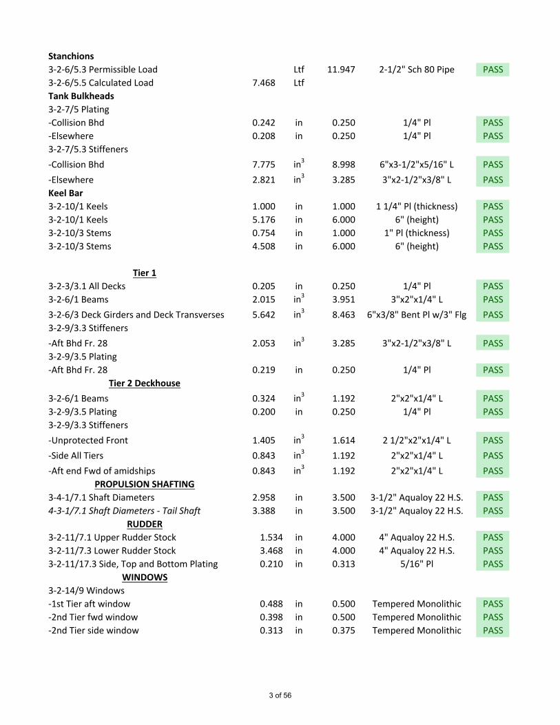
Stanchions3-2-6/5.3 Permissible Load Ltf 11.947 2-1/2" Sch 80 Pipe PASS3-2-6/5.5 Calculated Load 7.468 LtfTank Bulkheads3-2-7/5 Plating-Collision Bhd 0.242 in 0.250 1/4" Pl PASS-Elsewhere 0.208 in 0.250 1/4" Pl PASS3-2-7/5.3 Stiffeners-Collision Bhd 7.775 in3 8.998 6"x3-1/2"x5/16" L PASS-Elsewhere 2.821 in3 3.285 3"x2-1/2"x3/8" L PASSKeel Bar3-2-10/1 Keels 1.000 in 1.000 1 1/4" Pl (thickness) PASS3-2-10/1 Keels 5.176 in 6.000 6" (height) PASS3-2-10/3 Stems 0.754 in 1.000 1" Pl (thickness) PASS3-2-10/3 Stems 4.508 in 6.000 6" (height) PASS
Tier 13-2-3/3.1 All Decks 0.205 in 0.250 1/4" Pl PASS3-2-6/1 Beams 2.015 in3 3.951 3"x2"x1/4" L PASS3-2-6/3 Deck Girders and Deck Transverses 5.642 in3 8.463 6"x3/8" Bent Pl w/3" Flg PASS3-2-9/3.3 Stiffeners-Aft Bhd Fr. 28 2.053 in3 3.285 3"x2-1/2"x3/8" L PASS3-2-9/3.5 Plating-Aft Bhd Fr. 28 0.219 in 0.250 1/4" Pl PASS
Tier 2 Deckhouse3-2-6/1 Beams 0.324 in3 1.192 2"x2"x1/4" L PASS3-2-9/3.5 Plating 0.200 in 0.250 1/4" Pl PASS3-2-9/3.3 Stiffeners-Unprotected Front 1.405 in3 1.614 2 1/2"x2"x1/4" L PASS-Side All Tiers 0.843 in3 1.192 2"x2"x1/4" L PASS-Aft end Fwd of amidships 0.843 in3 1.192 2"x2"x1/4" L PASS
PROPULSION SHAFTING3-4-1/7.1 Shaft Diameters 2.958 in 3.500 3-1/2" Aqualoy 22 H.S. PASS4-3-1/7.1 Shaft Diameters - Tail Shaft 3.388 in 3.500 3-1/2" Aqualoy 22 H.S. PASS
RUDDER3-2-11/7.1 Upper Rudder Stock 1.534 in 4.000 4" Aqualoy 22 H.S. PASS3-2-11/7.3 Lower Rudder Stock 3.468 in 4.000 4" Aqualoy 22 H.S. PASS3-2-11/17.3 Side, Top and Bottom Plating 0.210 in 0.313 5/16" Pl PASS
WINDOWS3-2-14/9 Windows-1st Tier aft window 0.488 in 0.500 Tempered Monolithic PASS-2nd Tier fwd window 0.398 in 0.500 Tempered Monolithic PASS-2nd Tier side window 0.313 in 0.375 Tempered Monolithic PASS
3 of 56
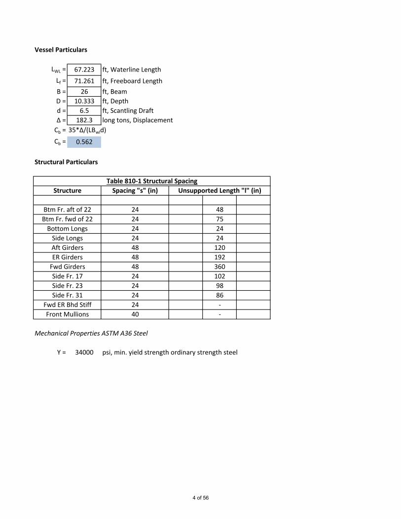
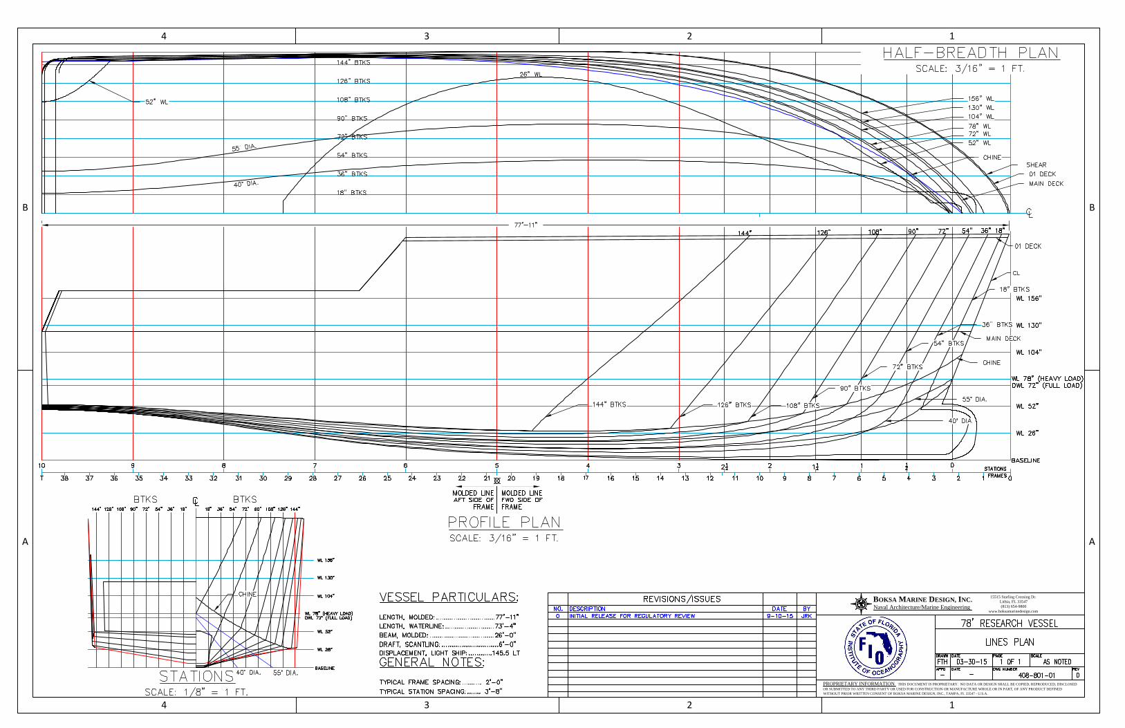
Vessel Particulars
LWL = 67.223 ft, Waterline LengthLf = 71.261 ft, Freeboard LengthB = 26 ft, BeamD = 10.333 ft, Depthd = 6.5 ft, Scantling DraftΔ = 182.3 long tons, Displacement
Cb = 35*Δ/(LBwld)Cb = 0.562
Structural Particulars
48752424
1201923601029886--
Mechanical Properties ASTM A36 Steel
Y = 34000 psi, min. yield strength ordinary strength steel
Side Fr. 23Side Fr. 31
Fwd ER Bhd StiffFront Mullions
24242440
Aft Girders
Unsupported Length "l" (in)
Btm Fr. fwd of 22 24
ER Girders
Table 810-1 Structural Spacing
Fwd GirdersSide Fr. 17
Spacing "s" (in)
24
242448484824
Structure
Btm Fr. aft of 22
Bottom LongsSide Longs
4 of 56
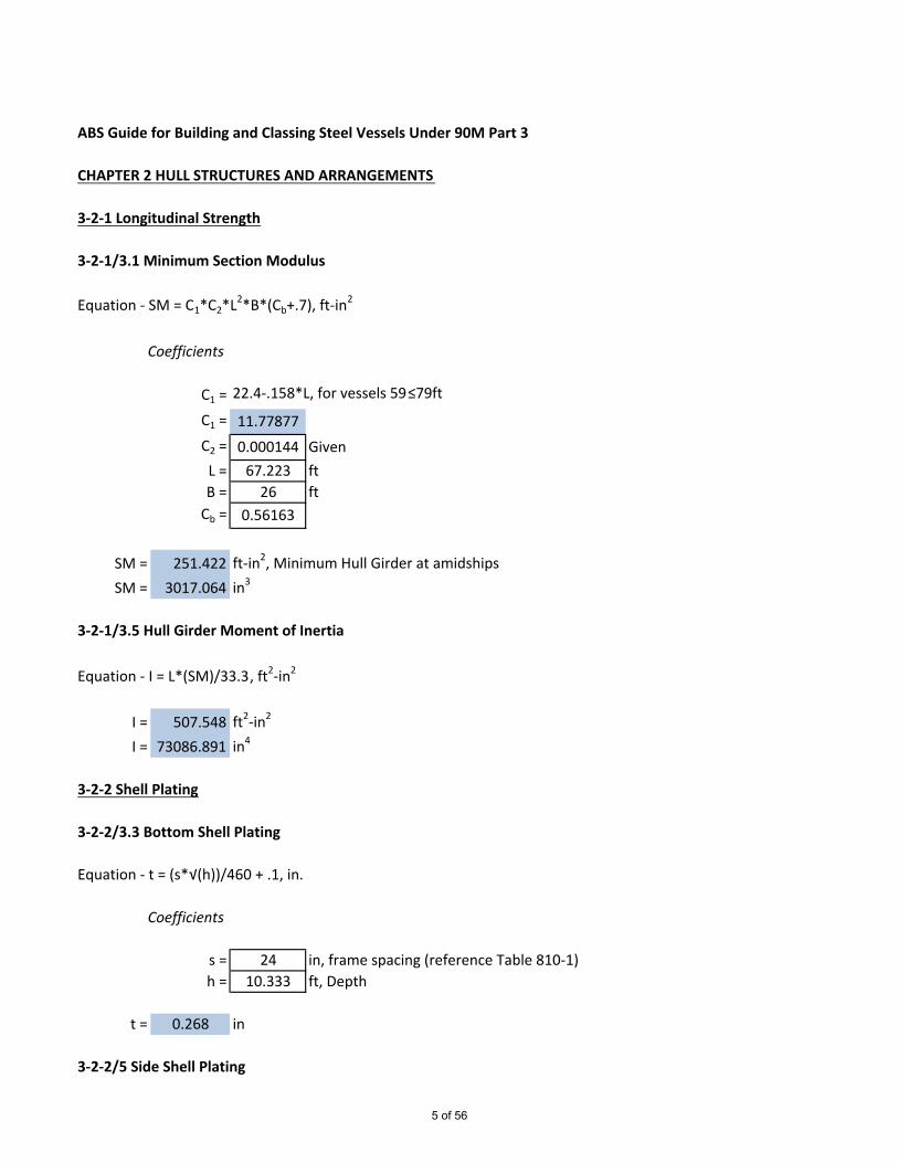
ABS Guide for Building and Classing Steel Vessels Under 90M Part 3
CHAPTER 2 HULL STRUCTURES AND ARRANGEMENTS
3-2-1 Longitudinal Strength
3-2-1/3.1 Minimum Section Modulus
Equation - SM = C1*C2*L2*B*(Cb+.7), ft-in2
Coefficients
C1 = 22.4-.158*L, for vessels 59≤79ft
C1 = 11.77877C2 = 0.000144 GivenL = 67.223 ftB = 26 ft
Cb = 0.56163
SM = 251.422 ft-in2, Minimum Hull Girder at amidshipsSM = 3017.064 in3
3-2-1/3.5 Hull Girder Moment of Inertia
Equation - I = L*(SM)/33.3, ft2-in2
I = 507.548 ft2-in2
I = 73086.891 in4
3-2-2 Shell Plating
3-2-2/3.3 Bottom Shell Plating
Equation - t = (s*√(h))/460 + .1, in.
Coefficients
s = 24 in, frame spacing (reference Table 810-1)h = 10.333 ft, Depth
t = 0.268 in
3-2-2/5 Side Shell Plating
5 of 56

Equation - t = (s*√(h))/485 + .1, in.
Coefficients
s = 24 in, frame spacing (reference Table 810-1)h = 10.333 ft, Depth
t = 0.259 in
3-2-2/5.5 Side Shell Plating at ends
Equation - t = .000545*L+.009*s, in
t = 0.253 in
3-2-2/5.7 Forecastle and Poop Side Plating
Equation - t = .00045*(L+103.3)+.006*s, in. Forecastle Plating
t = 0.221 in
3-2-2/7 Bow and Stern Thruster Tunnels
Equation - t = .008*d+.13, in.
Coefficients
d = 38 in, inside diameter of tunnel, but not less than 38
t = 0.434 in
3-2-3 Deck Plating
3-2-3/3.1 All Decks
Equation - t = (s*√(h))/460 + .1, in.
Coefficients
s = 24 in, frame spacing (reference Table 810-1)h = See Below
Equation 1 - h =.028*L+3.57, ft for exposed freeboard deck with no deckbelow
h = 5.452 ft
6 of 56

Equation 2 - h =.028*L+2.14, ft for exposed freeboard deck with a deckbelow, Forcastle deck, Superstructure deck Fwdof Amidships (.5*L)
h = 4.022 ft
Equation 3 - h =.014*L+2.86, ft Freeboard deck within superstructure,any deck below freeboard deck, superstructuredeck between .25L Fwd of and .2L aft of amidships
h = 3.801 ft
Equation 4 - h = .014*L+1.43, ft All other locations
h = 2.371 ft
For decks that make up tank top h is the greater of the following:
h1 = 4.875 ft, two-thirds the distance from the tank top tothe top of the overflow
h2 = 4.875 ft, two-thirds the distance from the tank top to thefreeboard deck
h = 4.875 ft
t = 0.222 in, for Exposed freeboard deck with no deck below
t = 0.205 in, for Exposed freeboard deck with deck below
t = 0.205 in, for Forcastle deck
t = 0.205 in, for Superstructure deck fwd of amidships
t = 0.202 in, Freeboard deck with Superstructure
t = 0.202 in, Any deck below freeboard deck
t = 0.202 in, Superstructure deck between .25L fwd of and .20L aft of amidships
t = 0.180 in, For decks at all other locations
t = 0.215 in, For decks that make up tank tops
3-2-4 Bottom Structure
7 of 56

3-2-4/3 Single Bottoms with Floors and Keelsons
3-2-4/3.7 FloorsNote: This calculation is for Transverse Framing. Only to be used if frames are continuousrelative to bottom girders
Equation 1 - SM = .0041*c*h*s*l2, in3
Coefficients
c = 0.55 Given
h = Not to be less than the following:
h1 = 6.5 ft, scantling drafth2 = 6.820 ft, .66*Dh3 = 4.437 ft, .066*L
h = 6.820 ft
s = 2 ft
l = 12.167 ft, Station 5
SM = 4.553 in3, Station 5
Equation 2 -hf = .75*l, in. mimimum depth of floor at centerline
hf = 9.125 in,
Equation 3 - t = .01*hf+.12, in. minimum thickess of floor
t = 0.211 in
3-2-4/5 Single Bottoms with Longitudinal or Transverse Frames
3-2-4/5.3 Bottom Girders and TransversesNote: This calculation is for the bottom girders. For transverse frames see 5.7
Equation 1 - SM = .0041*c*h*s*l2, in3
Coefficients
8 of 56
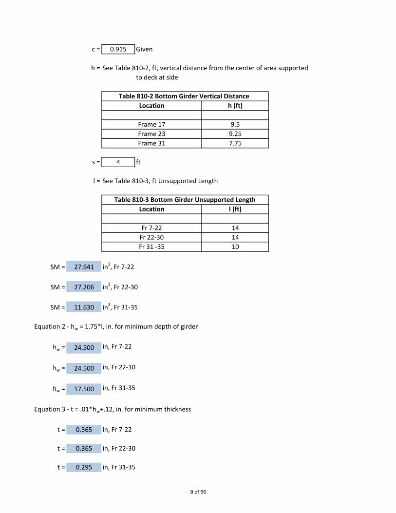
c = 0.915 Given
h = See Table 810-2, ft, vertical distance from the center of area supportedto deck at side
s = 4 ft
l = See Table 810-3, ft Unsupported Length
SM = 27.941 in3, Fr 7-22
SM = 27.206 in3, Fr 22-30
SM = 11.630 in3, Fr 31-35
Equation 2 - hw = 1.75*l, in. for minimum depth of girder
hw = 24.500 in, Fr 7-22
hw = 24.500 in, Fr 22-30
hw = 17.500 in, Fr 31-35
Equation 3 - t = .01*hw+.12, in. for minimum thickness
t = 0.365 in, Fr 7-22
t = 0.365 in, Fr 22-30
t = 0.295 in, Fr 31-35
Fr 7-22 14Fr 22-30 14Fr 31 -35 10
LocationTable 810-2 Bottom Girder Vertical Distance
h (ft)
Table 810-3 Bottom Girder Unsupported LengthLocation l (ft)
Frame 17Frame 23Frame 31
9.59.257.75
9 of 56

3-2-4/5.5 Center Girder
In general to be taken same as bottom girders
3-2-4/5.7 Frames
Equation 1 - SM = .0041*c*h*s*l2, in3
Coefficients
c = 0.8 Given, For transverse frame clear of tanks1 Given, For transverse frames in way of tanks
s = 2 ft
l = 6.25 ft, fwd of frame 22l = 4 ft, aft of frame 22
h = See Table 810-4, ft, vertical distance from the center of area supportedto deck at side
* h value for Frame 23 (due to tank) is the greater of the following:
h1 = 6.25 ft, two-thirds the distance from the tank top tothe top of the overflow
h2 = .01*L+.5 fth2 = 1.172 ft
h3 = 1.5 ft, Given
SM = 2.093 in3, Fr 21SM = 0.971 in3, Fr 23SM = 0.820 in3, Fr 26SM = 0.813 in3, Fr 31
*Frame 267.75
Table 810-4 Frame Vertical DistanceLocation h (ft)
9.25Frame 21 8.167Frame 23
6.250Frame 31
10 of 56
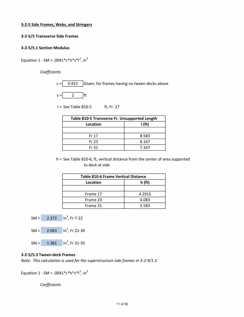
3-2-5 Side Frames, Webs, and Stringers
3-2-5/5 Transverse Side Frames
3-2-5/5.1 Section Modulus
Equation 1 - SM = .0041*c*h*s*l2, in3
Coefficients
c = 0.915 Given, for frames having no tween decks above
s = 2 ft
l = See Table 810-5 ft, Fr. 17
h = See Table 810-6, ft, vertical distance from the center of area supportedto deck at side
SM = 2.372 in3, Fr 7-22
SM = 2.043 in3, Fr 22-30
SM = 1.381 in3, Fr 31-35
3-2-5/5.3 Tween-deck FramesNote: This calculation is used for the superstructure side frames in 3-2-9/1.3
Equation 1 - SM = .0041*c*h*s*l2, in3
Coefficients
Table 810-5 Transverse Fr. Unsupported LengthLocation l (ft)
8.5838.1677.167
Fr 17Fr 23Fr 31
Table 810-6 Frame Vertical DistanceLocation h (ft)
Frame 31 3.583
Frame 17 4.2915Frame 23 4.083
11 of 56
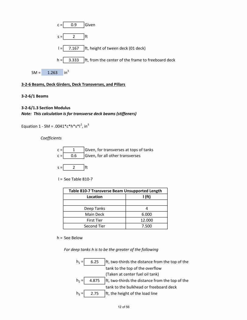
c = 0.9 Given
s = 2 ft
l = 7.167 ft, height of tween deck (01 deck)
h = 3.333 ft, from the center of the frame to freeboard deck
SM = 1.263 in3
3-2-6 Beams, Deck Girders, Deck Transverses, and Pillars
3-2-6/1 Beams
3-2-6/1.3 Section ModulusNote: This calculation is for transverse deck beams (stiffeners)
Equation 1 - SM = .0041*c*h*s*l2, in3
Coefficients
c = 1 Given, for transverses at tops of tanksc = 0.6 Given, for all other transverses
s = 2 ft
l = See Table 810-7
h = See Below
For deep tanks h is to be the greater of the following
h1 = 6.25 ft, two-thirds the distance from the top of thetank to the top of the overflow(Taken at center fuel oil tank)
h2 = 4.875 ft, two-thirds the distance from the top of thetank to the bulkhead or freeboard deck
h3 = 2.75 ft, the height of the load line
Deep TanksMain DeckFirst Tier
Second Tier
46.000
12.0007.500
Table 810-7 Transverse Beam Unsupported LengthLocation l (ft)
12 of 56

h4 = 1.172 ft, .01*L+.5
ht = 6.250 ft, for deep tanks
Elsewhere h is as follows
Equation 1 -h = .02*L+2.5 ft, Exposed freeboard deck having no deckbelow
h = 3.844 ft,
Equation 2 - h =.02*L+1.5, ft for exposed freeboard deck with a deckbelow, Forcastle deck, Superstructure deck Fwdof Amidships (.5*L)
h = 2.844 ft
Equation 3 - h =.01*L+2, ft Freeboard deck within superstructure,any deck below freeboard deck, superstructuredeck between .25L Fwd of and .3L aft of amidships
h = 2.672 ft
Equation 4 - h = .01*L+1, ft All Other First Tier Above Freeboard Decklocations
h = 1.672 ft
Equation 5 - .01*L+.5, ft, Second Tier above freeboard deck; deckhousetop, or superstructure
h = 1.172 ft
SM = 0.820 in3, For deep tanks
SM = 0.681 in3, For exposed freeboard deck with no deck below
SM = 0.504 in3, For exposed freeboard deck having a deck below, forcastle deck
SM = 2.015 in3, For first tier superstructure deck fwd of amidships
SM = 0.473 in3, For freeboard deck within superstructure, any deck below freeboarddeck
13 of 56
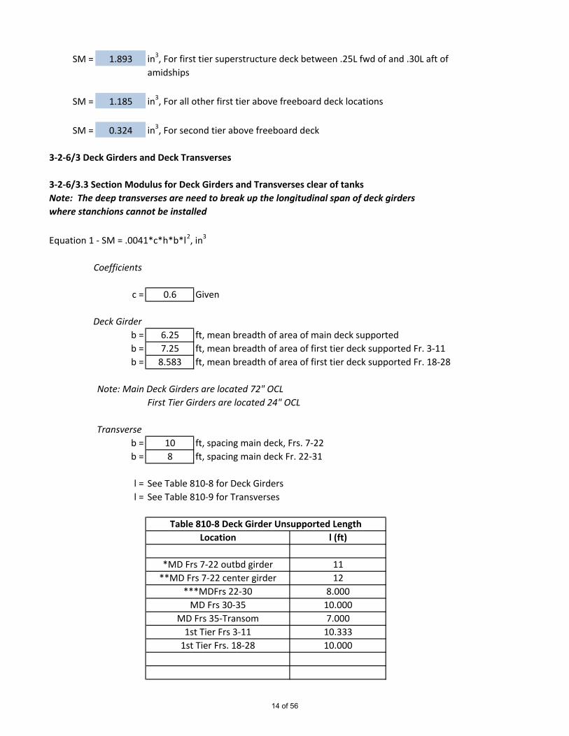
SM = 1.893 in3, For first tier superstructure deck between .25L fwd of and .30L aft ofamidships
SM = 1.185 in3, For all other first tier above freeboard deck locations
SM = 0.324 in3, For second tier above freeboard deck
3-2-6/3 Deck Girders and Deck Transverses
3-2-6/3.3 Section Modulus for Deck Girders and Transverses clear of tanksNote: The deep transverses are need to break up the longitudinal span of deck girderswhere stanchions cannot be installed
Equation 1 - SM = .0041*c*h*b*l2, in3
Coefficients
c = 0.6 Given
Deck Girderb = 6.25 ft, mean breadth of area of main deck supportedb = 7.25 ft, mean breadth of area of first tier deck supported Fr. 3-11b = 8.583 ft, mean breadth of area of first tier deck supported Fr. 18-28
Note: Main Deck Girders are located 72" OCLFirst Tier Girders are located 24" OCL
Transverseb = 10 ft, spacing main deck, Frs. 7-22b = 8 ft, spacing main deck Fr. 22-31
l = See Table 810-8 for Deck Girdersl = See Table 810-9 for Transverses
Table 810-8 Deck Girder Unsupported LengthLocation l (ft)
MD Frs 30-35MD Frs 35-Transom
1112
8.00010.0007.000
*MD Frs 7-22 outbd girder**MD Frs 7-22 center girder
***MDFrs 22-30
1st Tier Frs 3-11 10.3331st Tier Frs. 18-28 10.000
14 of 56

* Considered with stanchion at fr. 11.5 and 17** Considered with headers in way of 12 and 16.5*** Considered with deep deck transverse with stanchion on CL
h = See beam calculations above
Deck Girders
For Main Deck Girders from Fr. 7 - 22
SM = 4.971 in3, For side girders iwo freeboard deck within superstructure
SM = 5.916 in3, For center girder iwo freeboard deck within superstructure
For Main Deck Girders from Fr. 22 - 30
SM = 2.629 in3, For deck girders iwo freeboard deck within superstructure
For Main Deck Girders from Fr. 30 - 35
SM = 5.911 in3, For deck girders iwo exposed freeboard deck with deck below
For Main Deck Girders from Fr. 35 - Transom
SM = 2.896 in3, For deck girders iwo exposed freeboard deck with no deck below
For First Tier Deck Girders from Fr. 3-11
SM = 5.417 in3, For deck girders iwo first tier deck fwd of amidships
For First Tier Deck Girders from Fr. 18-28
SM = 5.642 in3, For deck girders iwo first tier deck between .25L Fwd of and .3L aft ofamidships
Deck Transverses
For Deck Transverse Frames 12 and 16.5
Fr. 12 and 16.5 12Fr. 26 9
Table 810-9 Transverses Unsupported LengthLocation l (ft)
15 of 56

SM = 9.466 in3, For main deck transverse iwo freeboard deck within superstructure
For Deck Transverse Frame 26
SM = 4.260 in3, For main deck transverse iwo freeboard deck within superstructure
3-2-6/5 Stanchions
3-2-6/5.3 Permissible Load
Equation - Wa = (k-(n*l/r))*A, Ltf
Coefficients
k = 7.83 Given
n = 0.345 Given
l = See Table 810-10
r = 0.924 in, least radius of gyration for 2-1/2" Sch. 80 Pipe
A = 2.25 in2, area of stanchion for 2-1/2" Sch. 80 Pipe
Wa = 11.947 Ltf, Main Deck Stanchion
Wa = 11.737 Ltf, First Tier Stanchion
3-2-6/5.5 Calculated Load
Equation - W = n*b*h*s, Ltf
Coefficients
n = 0.02 Given
b = See Table 810-11
h = See Below
Location l (ft)
Main Deck Frs. 11.5, 17, 26 6.75
Table 810-10 Stanchion Unsupported Length
First Tier Fr. 5.5 7
16 of 56

Stanchions below freeboard deckh = .02*L+2.5 fth = 3.844 ft
Stanchions below first tier deckh = .02*L+1.5 fth = 2.844 ft
s = See Table 810-12
W = 7.468 Ltf, for stanchions below freeboard deck
W = 3.343 Ltf, for stanchions below first tier deck
3-2-7 Watertight Bulkheads and Doors
3-2-7/3.1 Collision Bulkhead
Location of Collision Bhd
Equation - Location = .05*Lf
Location = 3.563 ft
3-2-7/5 Plating
Equation - t = (s*k*√(q*h))/c+.06, in.
Coefficients
s = 24 in
k = 1 Given, for aspect ratio >2
10.5First Tier Fr. 5.5 7.75
Table 810-12 Stanchion Mean Length SupportedLocation s (ft)
Main Deck Stanchion at Fr 17 9.25First Tier Stanchion at Fr. 5.5 7.583
Table 810-11 Stanchion Mean Breadth SupportedLocation b (ft)
Main Deck Stanchion at Fr 17
17 of 56
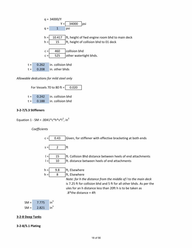
q = 34000/YY = 34000 psi
q = 1 psi
h = 10.417 ft, height of fwd engine room bhd to main deckh = 15 ft, height of collision bhd to 01 deck
c = 460 collision bhdc = 525 other watertight bhds.
t = 0.262 in. collision bhdt = 0.208 in. other bhds
Allowable dedcutions for mild steel only
For Vessels 70 to 80 ft = 0.020
t = 0.242 in. collision bhdt = 0.188 in. collision bhd
3-2-7/5.3 Stiffeners
Equation 1 - SM = .0041*c*h*s*l2, in3
Coefficients
c = 0.43 Given, for stiffener with effective bracketing at both ends
s = 2 ft
l = 15 ft. Collision Bhd distance between heels of end attachmentsl = 10 ft. distance between heels of end attachments
h = 9.8 ft, Elsewhereh = 8 ft, Elsewhere
Note: for h the distance from the middle of l to the main deckis 7.25 ft for collision bhd and 5 ft for all other bhds. As per theules for an h distance less than 20ft h is to be taken as .8*the distance + 4ft
SM = 7.775 in3
SM = 2.821 in3
3-2-8 Deep Tanks
3-2-8/5.1 Plating
18 of 56

Equation - t = (s*k*√(q*h))/460+.1, in.
Coefficients
s = 24
k = 0.985 for (1 ≤ α ≤ 2), k = (3.075*√(α)-2.077/(α + .272)
α = 1.755 aspect ratio (longest edge/shorter edge)Note: longest edge of aspect ratio taken as height frombottom shell to tank top for fr. 12 tank boudary
q = 34000/YY = 34000
q = 1
h = 4.875 ft, The greatest of the following:
h1 = 4.875 ft, two-thirds of the distance to the deck
h2 = 4.875 ft, two-thirds the distance from the top of thetank to the top of the overflow
h3 = 3 ft, the load line
h4 = 1.172 ft, .01*L+.5ft
h5 = 1.5 ft
t = 0.213 in.
3-2-8/5.3 Stiffeners
Equation 1 - SM = .0041*c*h*s*l2, in3
Coefficients
c = 0.594 Given, for stiffener with effective bracketing at both ends
s = 2 ft
l = 3.333 ft. distance between heels of end attachments
h = 4.875 ft, reference h values for 5.1 Plating
SM = 0.264 in3
19 of 56
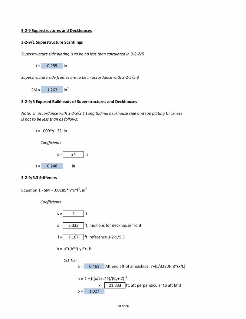
3-2-9 Superstructures and Deckhouses
3-2-9/1 Superstructure Scantlings
Superstructure side plating is to be no less than calculated in 3-2-2/5
t = 0.259 in
Superstructure side frames are to be in accordance with 3-2-5/5.3
SM = 1.263 in3
3-2-9/3 Exposed Bulkheads of Superstructures and Deckhouses
Note: In accordance with 3-2-9/3.1 Longitudinal deckhouse side and top plating thicknessis not to be less than as follows:
t = .009*s+.32, in.
Coefficients
s = 24 in
t = 0.248 in
3-2-9/3.3 Stiffeners
Equation 1 - SM = .00185*h*s*l2, in3
Coefficients
s = 2 ft
s = 3.333 ft, mullions for deckhouse front
l = 7.167 ft. reference 3-2-5/5.3
h = a*((b*f)-y)*c, ft
1st Tiera = 0.461 Aft end aft of amidships .7+(L/3280)-.8*(x/L)
b = 1 + (((x/L)-.45)/(Cb+.2))2
x = 21.833 ft, aft perpendicular to aft bhdb = 1.027
20 of 56

f = 4.09 Given, 3-2-9/Table 2
y = 7.833 ft, vertical distance from summer load line to midstiffener span
c = .3+(.7*b1/B1)b1 = 26 ft
B1 = 25.5 ftc = 1.014
h = -1.696 ftNote: h is not to be taken as less than 10.8 ft for first tier
h = 10.800 ft
2nd Tier
a = 1.171 Unprotected front second tier 1+L/393.6a = 0.637 Sides - .5+L/492a = 0.283 Aft end fwd of amidships .5+(L/3280)-.4*(x/L)
b = 1+1.5*(((x/L)-.45)/(Cb+.2))2
x = 39.833 ft, aft perpendicular to aft bhdx = 50.75 ft, aft perpendicular to mid side bhdx = 61.833 ft, aft perpendicular to fwd bhd
b = 1.053 aft bhdb = 1.240 side bhdb = 1.571 front bhd
y = 15.167 ft, vertical distance from summer load line to midstiffener span
c = .3+(.7*b1/B1)b1 = 16 ft
B1 = 25.5 ftc = 0.739
h = -9.401 ft, aft bhd-4.750 ft, side bhd-1.832 ft, front bhd
Note: h is not to be taken as less than 4.1+L/200, ft = 4.436 ft
21 of 56

h = 4.436 ft, aft bhdh = 4.436 ft, side bhdh = 4.436 ft, front bhd
1st TierSM = 2.053 in3, aft bhd stiffeners
2nd Tier
SM = 0.843 in3, aft bhd stiffenersSM = 0.843 in3, side bhd stiffenersSM = 1.405 in3, front bhd stiffeners
3-2-9/3.5 Plating
Equation - t = s*√(h)/50
1st Tiert = 0.131 in, aft end bhd
Note: t for the lowest tier is not to be less than the following:
t = (s/1.97)*(.2+.00024*L)t = 0.219 in
Use t = 0.219 in, aft end bhd
2nd Tier
t = 0.084 in, aft end bhdt = 0.084 in, side bhdt = 0.140 in, front bhd
Note: t for the second tier is not to be less than .2in
Use t= 0.200 in, aft end bhdUse t= 0.200 in, side bhdUse t= 0.200 in, front bhd
3-2-10 Keels, Stems, Stern Frames, Shaft Struts, and Propeller Nozzles
3-2-10/1 Keels
Equation 1 - t = .0075*L+.5, in. thickness of keel bar
Equation 2 - h = .0175*L+4, in. height of keel bar
t = 1.004 inUse t = 1.000 in
22 of 56

h = 5.176 in
3-2-10/3 Stems
Equation 1 - t = .0075*L+.25, in. thickness of bar stem
Equation 2 - w = .015*L+3.5, in. width of bar stem
t = 0.754 in
w = 4.508 in
3-2-10/17 Shaft Struts
3-2-10/17.3 V Strut
Equation 1 - Moment of intertia - Ixx = .0044D4
Equation 2 - Section Modulus - SMxx = .024D3
D = 3.5 in, Shaft diameter
Ixx = 0.660 in4, For each strut arm
SMxx = 1.029 in3, For each strut arm
3-2-11 Rudders and Steering Equipment
3-2-11/1.3 Materials for Rudder, Rudder Stock and Steering Equipment
Equation 1 -K = (ny/Y)e
ny
(psi)U
(psi)Yeq
(psi)e
Ym
(psi).7U(psi)
Rudder Stock, Ks = 0.615 34000 130000 65000 0.75 65,000 91000Coupling Flange, Kf = 1.000 34000 58000 34000 1 34000 40600
Flange bolts, Kb = 0.810 34000 91000 45000 0.75 45000 63700
3-2-11/3 Rudder Design Force
3-2-11/3.1 Rudder Blades without Cutouts
Equation 1 - CR = nkRkcklAVR2
Material Factor
23 of 56

n = 0.00123 Given Coefficient
kR = (b2/At+2)/3
b= 3.167 ft, mean height of rudder areafrom Figure 3-2-11/Fig. 1
At = 6.742 ft2, sum of rudder blade area A, and rudder post
or rudder horn within extension of rudder profilekR = 1.163
A = 5.6 ft2, total projected area of rudder (from working drawing)
kcA = 1.1 from 3-2-11/Table 1A, Ahead ConditionkcAs = 0.8 from 3-2-11/Table 1A, Astern Condition
kl = 1 from 3-2-11/Table 2
VRA > of Vd or Vmin, knots in ahead conditionVRAS > of Va or .5*Vd or .5Vmin, knots in asterncondition
Vd = 12 knots, design speed running ahead at max. cont.rated shaft rpm at the summer load line
.5*Vd = 6Vmin = (Vd +20)/3Vmin = 10.667 knots
.5*Vmin = 5.333 knots
Va = 4 knots, max. astern speed
VRA = 12 knots, ahead conditionVRAS = 6 knots, astern condition
CRA = 1.268 Ltf, ahead conditionCRA = 0.231 Ltf, astern condition
CR = 1.268 Ltf
3-2-11/5 Rudder Design Torque
3-2-11/5.3 Rudder Blades without Cutouts
24 of 56

Equation 1 - QR = CRr
r = c(α-k), but not less than .1*c for ahead condition
c = 3.389 ft, mean breadth of rudder
.1*c = 0.3389 ft, for ahead condition
k = Af/AAf = 1.804 ft2, area of rudder fwd of rudder stock
centerlinek = 0.322
αA = 0.33 from 3-2-11/Table 3, ahead condition
αAS = 0.75 from 3-2-11/Table 3, astern condition
rA = 0.027 for ahead conditionUse rA= 0.339 for ahead condition
rAS = 1.450 for astern condition
QRA = 0.430 Ltf-ft, ahead conditionQRAS = 0.334 Ltf-ft, astern condition
3-2-11/7 Rudder Stocks
3-2-11/7.1 Upper Rudder Stock
Equation 1 - S = Nu*(QRKs)^(1/3)
Nu = 2.39 GivenKs = 0.615 Material Factor
SA = 1.534 inSAS = 1.411 in
Use S = 2.000 in
3-2-11/7.3 Lower Rudder Stock
Equation 1 - Sl = S*(1+(4/3)*(M/QR)2)^(1/6)
Sl = 3.468 in
25 of 56

Use Sl = 4.000 in
3-2-11/7.5 Bending Moments
Equation 1 - Mn = CR*ln (For Spade Rudders at neck bearing)Equation 2 - Ms = CR*(A1/A)*lc (For Spade Rudders at section under consideration)
ln = 1.502 ft, distance from center of neck bearing to centroid of rudderarea
lc1 = 1.139 ft, distance from section under consideration to the centroidof rudder area A1, Upper diaphragm
lc2 = 0.77 ft, distance from section under consideration to the centroidof rudder area A1, 2nd diaphragm
lc3 = 0.39 ft, distance from section under consideration to the centroidof rudder area A1, lower diaphragm
A11 = 4.038 ft2, area under upper diaphragm
A12 = 2.584 ft2, area under 2nd diaphragm
A13 = 1.238 ft2, area under lower diaphragm
Mn = 1.905 Ltf-ft
Ms1 = 1.042 Ltf-ft, Upper Diaphragm
Ms2 = 0.451 Ltf-ft, 2nd Diaphragm
Ms3 = 0.109 Ltf-ft, Lower Diaphragm
3-2-11/9.3 Horizontal Couplings
Equation 1 - db = .62*sqrt(ds3*Kb/(nrKs)) Coupling bolts
Equation 2 - tf = dbt*sqrt(Kf/Kb) Coupling flangeEquation 3 - tf = .9*dbt
ds = 2.000 in, diamter upper rudder stock
dsl = 4.000 in, diameter lower rudder stock
n = 6 minimum number of bolts allowed
r = 8 in, mean distance of the bolt axes from the center of
26 of 56

bolt systemKb = 0.810 for 316 stainless bolts Reference 3-2-11/1.3
Kf = 1.000 for Astm A36 steel Reference 3-2-11/1.3
Ks = 0.615 for Aqualoy 22 HS Reference 3-2-11/1.3
dbs = 0.291 in, upper rudder stockdbsl = 0.822 in, lower rudder stock
Eq 2 tfs = 0.323 in, upper rudder stock flangeEq 2 tfsl = 0.913 in, lower rudder stock flange
Eq 3 tfs = 0.261 in, upper rudder stock flangeEq 3 tfsl = 0.740 in, lower rudder stock flange
Use tfs = 0.323 in, Greater of equations 2 and 3Use tfsl = 0.913 in, Greater of equations 2 and 3
3-2-11/13.5 Shear and Bearing Forces
Equation 1 - Pu = Mn/lu Bearing Force at Rudder CarrierEquation 2 - Pn = Cr+Pu Bearing Force at Neck BearingEquation 3 - Fn = Cr Shear Force at Neck Bearing
lu = 3.5 ft, distance between center of neck bearing and thecenter of the rudder carrier bearing
Pu = 0.544 Ltf
Pn = 1.813 Ltf
Fn = 1.268 Ltf
3-2-11/17 Double Plate Rudder
3-2-11/17.1 Strength
Equation 1 = σb = Kσ/Q Bending StressEquation 2 - τ = Kτ/Q Shear Stress
Equation 3a - σe = sqrt(σb2+3τ2) Equivalent Strength
Equation 3b - σe = Ke/Q
27 of 56
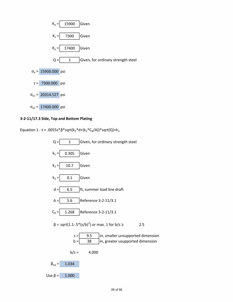
Kσ = 15900 Given
Kτ = 7300 Given
Ke = 17400 Given
Q = 1 Given, for ordinary strength steel
σb = 15900.000 psi
τ = 7300.000 psi
σe1 = 20314.527 psi
σe2 = 17400.000 psi
3-2-11/17.3 Side, Top and Bottom Plating
Equation 1 - t = .0055s*β*sqrt(k1*d+(k2*CR/A))*sqrt(Q)+k3
Q = 1 Given, for ordinary strength steel
k1 = 0.305 Given
k2 = 10.7 Given
k3 = 0.1 Given
d = 6.5 ft, summer load line draft
A = 5.6 Reference 3-2-11/3.1
CR = 1.268 Reference 3-2-11/3.1
β = sqrt(1.1-.5*(s/b)2) or max. 1 for b/s ≥ 2.5
s = 9.5 in, smaller unsupported dimensionb = 38 in, greater usupported dimension
b/s = 4.000
βeq = 1.034
Use β = 1.000
28 of 56

t = 0.210 in
Use t = 0.313 in
3-2-11/17.5 Diaphragm Plates
Thickness of diaphragm plates are to be 70% of required rudder plate thickness or .31in,whichever is greater
Use tdp = 0.313 in
3-2-14 Bulwarks, Rails, Freeing Ports, Portlights, Windows, Ventilators, Tank Vents &Overflows
3-2-14/5 Freeing Ports
Equation - A = 7.6+.115*l, ft2 freeing port basic area
Coefficients
l = 26.75 ft, bulwark length
A = 10.676 ft2
3-2-14/7 Portlights
The lowest point of the portlights above the design water line are to be the greater distance ofthe following:
h1 = 2.5%*B = 0.65 ft = 7.8 in
h2 = 19.500 in
h = 19.500 in
3-2-14/9 WindowsNote: Consider tempered monolithic glassWindow thickness is to be the greater of the following:
Equation 1 - t = s*√(p*k/σa)
Equation 2 - t = s*(3√(p*k1/.02*E))
Coefficients
29 of 56
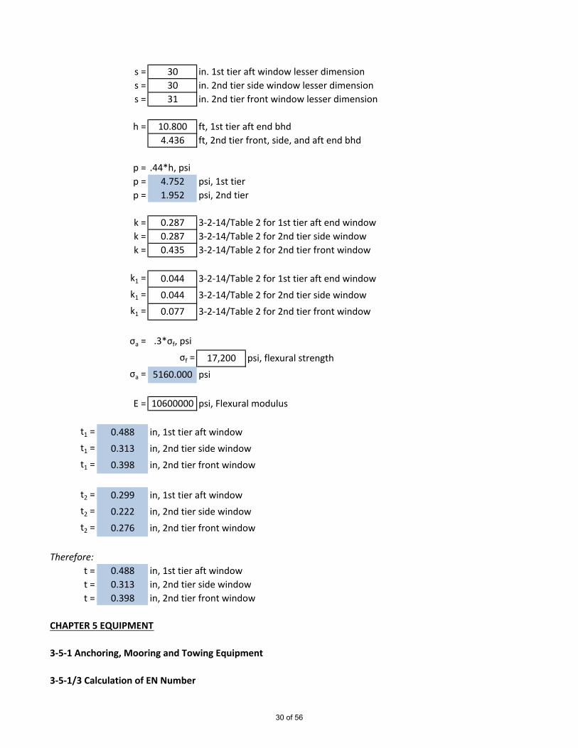
s = 30 in. 1st tier aft window lesser dimensions = 30 in. 2nd tier side window lesser dimensions = 31 in. 2nd tier front window lesser dimension
h = 10.800 ft, 1st tier aft end bhd4.436 ft, 2nd tier front, side, and aft end bhd
p = .44*h, psip = 4.752 psi, 1st tierp = 1.952 psi, 2nd tier
k = 0.287 3-2-14/Table 2 for 1st tier aft end windowk = 0.287 3-2-14/Table 2 for 2nd tier side windowk = 0.435 3-2-14/Table 2 for 2nd tier front window
k1 = 0.044 3-2-14/Table 2 for 1st tier aft end windowk1 = 0.044 3-2-14/Table 2 for 2nd tier side windowk1 = 0.077 3-2-14/Table 2 for 2nd tier front window
σa = .3*σf, psiσf = 17,200 psi, flexural strength
σa = 5160.000 psi
E = 10600000 psi, Flexural modulus
t1 = 0.488 in, 1st tier aft windowt1 = 0.313 in, 2nd tier side windowt1 = 0.398 in, 2nd tier front window
t2 = 0.299 in, 1st tier aft windowt2 = 0.222 in, 2nd tier side windowt2 = 0.276 in, 2nd tier front window
Therefore:t = 0.488 in, 1st tier aft windowt = 0.313 in, 2nd tier side windowt = 0.398 in, 2nd tier front window
CHAPTER 5 EQUIPMENT
3-5-1 Anchoring, Mooring and Towing Equipment
3-5-1/3 Calculation of EN Number
30 of 56

Equation - EN = k*Δ2/3+m*B*h+n*A
Coefficients
k = 1.012 Givenm = 0.186 Givenn = 0.00929 GivenΔ = 182.3 long tonnesB = 26 fth = a+h1+h2
a = 4.333 fth1 = 6.917 fth2 = 7.083 ft
h = 18.333 ftA = 1221.038 ft2
EN = 132.540
31 of 56

ABS Guide for Building and Classing Steel Vessels Under 90M Part 4
3-4-1/7 Design Constrcution
3-4-1/7.1 Shaft Diameters
Equation 1 - D = 100*K*((H/R)(c1/(U+c2)))(1/3)
c1 = 3.55 For vessels 65ft - 150ft, material of shaft other than Grade 2
c2 = 23180 Given Coefficient
K1a = 1 From 4-3-1/Table 1, shrink fit coupling
K1b = 1.1 From 4-3-1/Table 1, Keyways
K2a = 1.22 From 4-3-1/Table 2, Water Lubricated bearings w/cont. linersShrink fit Propeller Attachment
K2b = 1.26 From 4-3-1/Table 2, Water Lubricated bearings w/cont. linersKeyed Propeller Attachment
K2c = 1.15 From 4-3-1/Table 2, Water Lubricated bearings w/cont. linersStern Tube Shafts
H = 600 HP, Power at rated speed
R = 715.1371 rpm at rated speed
U = 130000 psi, Aqualoy 22 High Strength Ultimate Tensile Strength
D1a = 2.689 in, for line and thrust shafts with press fit couplingD1b = 2.958 in, for line and thrust shafts with keywaysD2a = 3.281 in, for tail shafts with shrink fit connectionD2b = 3.388 in, for tail shafts with keyed connectionD2c = 3.092 in, for stern tube shafts
Use D = 3.500 in
4-3-1/9 Key
Equation 2 - A = (D3/5.1*rm)*(Ys/Yk)
rm = 1.25 in, shaft radius at mid-length of key
32 of 56
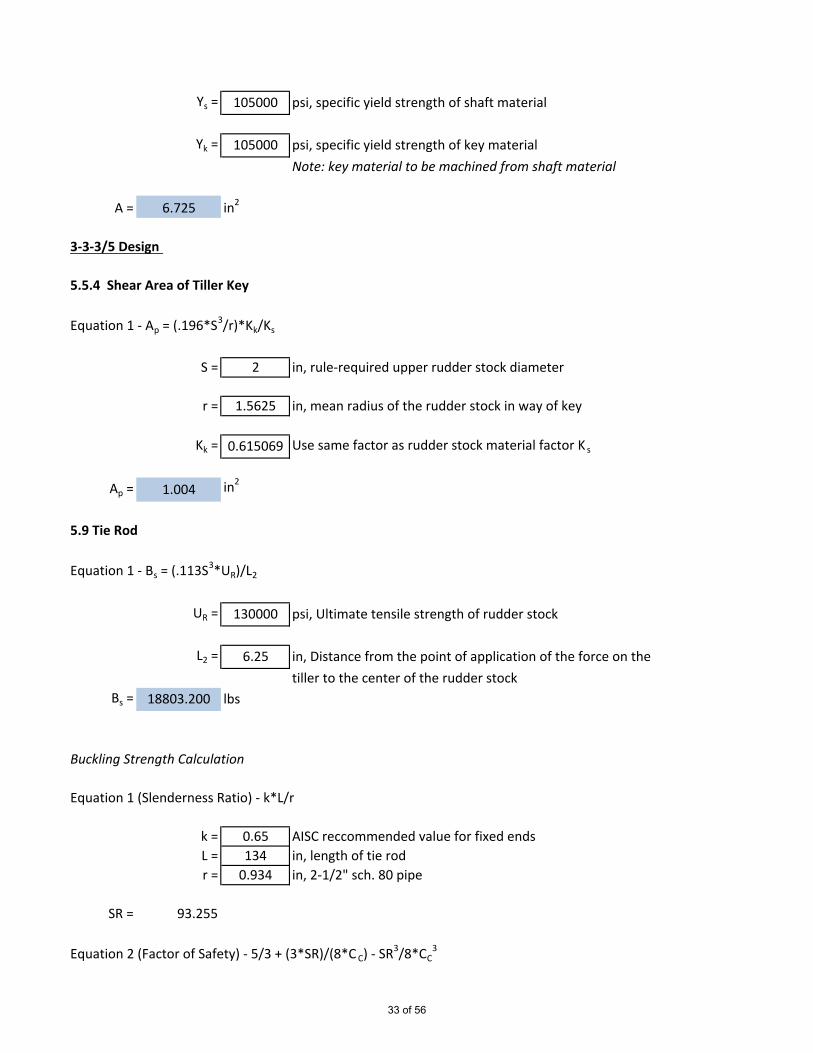
Ys = 105000 psi, specific yield strength of shaft material
Yk = 105000 psi, specific yield strength of key materialNote: key material to be machined from shaft material
A = 6.725 in2
3-3-3/5 Design
5.5.4 Shear Area of Tiller Key
Equation 1 - Ap = (.196*S3/r)*Kk/Ks
S = 2 in, rule-required upper rudder stock diameter
r = 1.5625 in, mean radius of the rudder stock in way of key
Kk = 0.615069 Use same factor as rudder stock material factor K s
Ap = 1.004 in2
5.9 Tie Rod
Equation 1 - Bs = (.113S3*UR)/L2
UR = 130000 psi, Ultimate tensile strength of rudder stock
L2 = 6.25 in, Distance from the point of application of the force on thetiller to the center of the rudder stock
Bs = 18803.200 lbs
Buckling Strength Calculation
Equation 1 (Slenderness Ratio) - k*L/r
k = 0.65 AISC reccommended value for fixed endsL = 134 in, length of tie rodr = 0.934 in, 2-1/2" sch. 80 pipe
SR = 93.255
Equation 2 (Factor of Safety) - 5/3 + (3*SR)/(8*C C) - SR3/8*CC3
33 of 56
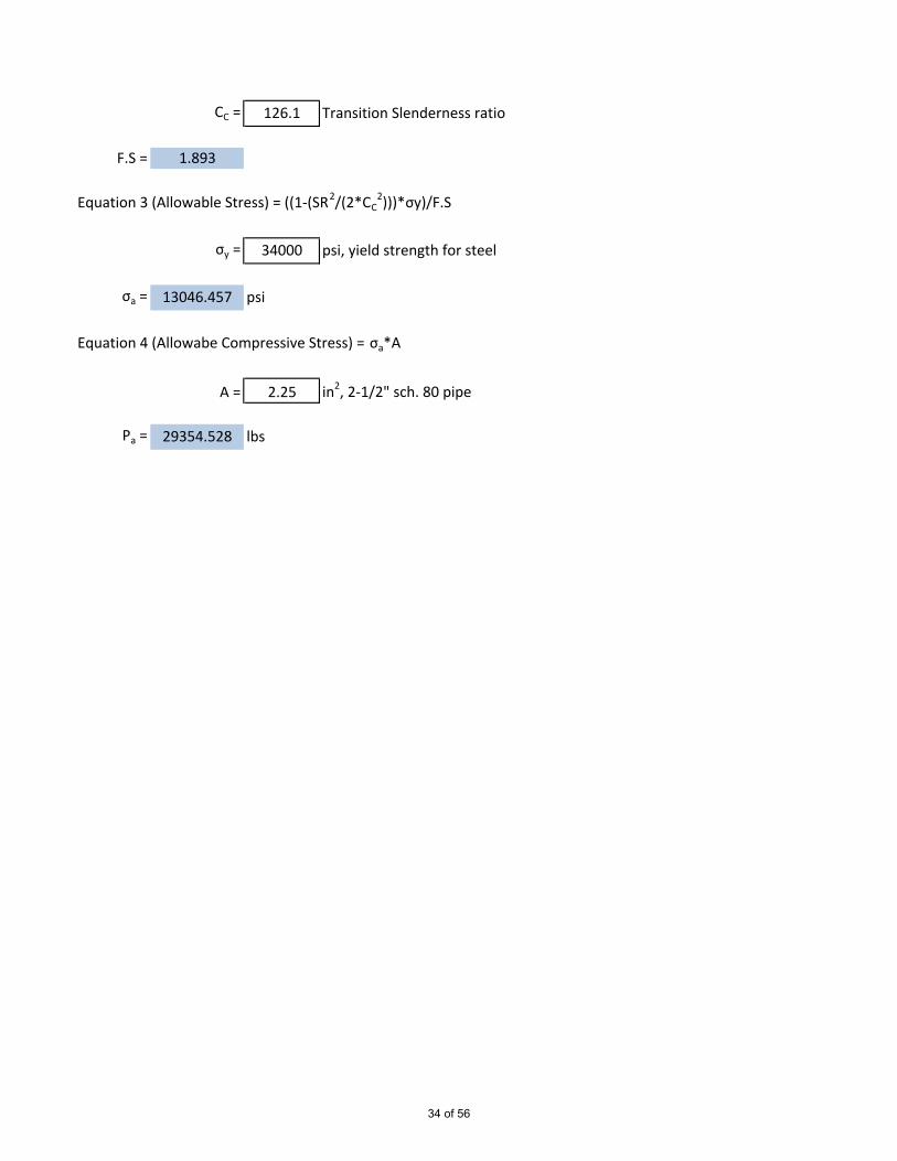
CC = 126.1 Transition Slenderness ratio
F.S = 1.893
Equation 3 (Allowable Stress) = ((1-(SR2/(2*CC2)))*σy)/F.S
σy = 34000 psi, yield strength for steel
σa = 13046.457 psi
Equation 4 (Allowabe Compressive Stress) = σa*A
A = 2.25 in2, 2-1/2" sch. 80 pipe
Pa = 29354.528 lbs
34 of 56

Aqualoy Propeller Shafting
Shaft Diameter
D = ((321000*P*S.F)/(S*N))^(1/3)
P = 600 HP, shaft HPS.F = 10 Safety Factor
S = 70000 psi, Yield strength in torsionN = 720 rpm, shaft speed
D = 3.368 in
Bearing Spacing
L =sqrt ((3.21*D)/N) * (E/W1)^(1/4)
D = 3.5 in, shaft diameterN = 720 Shaft SpeedE = 28900000 psi, Modulus of elasticity
W1 = 0.285 lbs, weight of one cubic inch
L = 12.535 ft
35 of 56

Bottom Girder Fr. 7 -22,Plate = 0.313 in =
s = 47.520 in =Web t = 0.375 in =Web d = 12.200 in =Flg t = 0.250 in =Flg d = 48.000 in =
Part b h A=b*h y A*y A*(Ybar - y)2 Io=bh^3/12Shell 47.520 0.313 14.850 12.606 187.203 478.578 0.121Web 0.375 12.200 4.575 6.350 29.051 1.535 56.745Flange 48.000 0.250 12.000 0.125 1.500 555.586 0.063
12.763 31.425 19.081 217.754 1035.700 56.929
Area = 31.425 in^2 Area = SA=b*h Total Cross Sectional AreaYbar = 6.929 in Ybar = SA*y/Area Centroid LocationI-n/a = 1092.628 in^4 I-n/a = ΣIo + A*(Ybar - y)2Moment of Inertia About Neutral AxisSMTOP = 187.313 in^3 SMTOP = I-n/a / (h-Ybar) Section Modulus TopSMBTM = 157.682 in^3 SMBTM = I-n/a / Ybar Section Modulus BottomAw = 4.575 in^2 Web area
Bottom Girder Fr. 22 -30Plate = 0.250 in =
s = 48.000 in =Web t = 0.375 in =Web d = 18.313 in =Flg t = 0.750 in =Flg d = 5.000 in =
Part b h A=b*h y A*y A*(Ybar - y)2 Io=bh^3/12Shell 48.000 0.250 12.000 19.188 230.250 423.005 0.063Web 0.375 18.313 6.867 9.906 68.028 76.793 191.908Flange 5.000 0.750 3.750 0.375 1.406 621.649 0.176
19.313 22.617 29.469 299.684 1121.448 192.146
Area = 22.617 in^2 Area = SA=b*h Total Cross Sectional AreaYbar = 13.250 in Ybar = SA*y/Area Centroid LocationI-n/a = 1313.594 in^4 I-n/a = ΣIo + A*(Ybar - y)2Moment of Inertia About Neutral AxisSMTOP = 216.686 in^3 SMTOP = I-n/a / (h-Ybar) Section Modulus TopSMBTM = 99.137 in^3 SMBTM = I-n/a / Ybar Section Modulus BottomAw = 6.867 in^2 Web area
36 of 56

Bottom Girder Fr. 30-35Plate = 0.250 in =
s = 39.600 in =Web t = 0.375 in =Web d = 17.500 in =Flg t = 0.250 in =Flg d = 4.000 in =
Part b h A=b*h y A*y A*(Ybar - y)2 Io=bh^3/12Shell 39.600 0.250 9.900 17.875 176.963 187.482 0.052Web 0.375 17.500 6.563 9.000 59.063 134.268 167.480Flange 4.000 0.250 1.000 0.125 0.125 179.513 0.005
18.000 17.463 27.000 236.150 501.264 167.537
Area = 17.463 in^2 Area = SA=b*h Total Cross Sectional AreaYbar = 13.523 in Ybar = SA*y/Area Centroid LocationI-n/a = 668.801 in^4 I-n/a = ΣIo + A*(Ybar - y)2Moment of Inertia About Neutral AxisSMTOP = 149.395 in^3 SMTOP = I-n/a / (h-Ybar) Section Modulus TopSMBTM = 49.456 in^3 SMBTM = I-n/a / Ybar Section Modulus BottomAw = 6.563 in^2 Web area
Main Deck Girder Fr. 35 -TransomPlate = 0.250 in =
s = 27.720 in =Web t = 0.375 in =Web d = 5.625 in =Flg t = 0.375 in =Flg d = 3.000 in =
Part b h A=b*h y A*y A*(Ybar - y)2 Io=bh^3/12Shell 27.720 0.250 6.930 6.125 42.446 11.121 0.036Web 0.375 5.625 2.109 3.188 6.724 5.888 5.562Flange 3.000 0.375 1.125 0.188 0.211 24.543 0.013
6.250 10.164 9.500 49.381 41.551 5.611
Area = 10.164 in^2 Area = SA=b*h Total Cross Sectional AreaYbar = 4.858 in Ybar = SA*y/Area Centroid LocationI-n/a = 47.162 in^4 I-n/a = ΣIo + A*(Ybar - y)2Moment of Inertia About Neutral AxisSMTOP = 33.886 in^3 SMTOP = I-n/a / (h-Ybar) Section Modulus TopSMBTM = 9.708 in^3 SMBTM = I-n/a / Ybar Section Modulus BottomAw = 2.109 in^2 Web area
37 of 56

First Tier Deck Girder Fr. 3-11Plate = 0.250 in =
s = 47.520 in =Web t = 0.313 in =Web d = 5.688 in =Flg t = 0.313 in =Flg d = 3.000 in =
Part b h A=b*h y A*y A*(Ybar - y)2 Io=bh^3/12Shell 47.520 0.250 11.880 6.125 72.765 6.593 0.062Web 0.313 5.688 1.777 3.156 5.610 8.790 4.791Flange 3.000 0.313 0.938 0.156 0.146 25.583 0.008
6.250 14.595 9.438 78.521 40.965 4.861
Area = 14.595 in^2 Area = SA=b*h Total Cross Sectional AreaYbar = 5.380 in Ybar = SA*y/Area Centroid LocationI-n/a = 45.825 in^4 I-n/a = ΣIo + A*(Ybar - y)2Moment of Inertia About Neutral AxisSMTOP = 52.677 in^3 SMTOP = I-n/a / (h-Ybar) Section Modulus TopSMBTM = 8.518 in^3 SMBTM = I-n/a / Ybar Section Modulus BottomAw = 1.777 in^2 Web area
First Tier Deck Girder Fr. 18-28Plate = 0.250 in =
s = 39.600 in =Web t = 0.313 in =Web d = 5.688 in =Flg t = 0.313 in =Flg d = 3.000 in =
Part b h A=b*h y A*y A*(Ybar - y)2 Io=bh^3/12Shell 39.600 0.250 9.900 6.125 60.638 7.354 0.052Web 0.313 5.688 1.777 3.156 5.610 7.890 4.791Flange 3.000 0.313 0.938 0.156 0.146 24.450 0.008
6.250 12.615 9.438 66.394 39.694 4.850
Area = 12.615 in^2 Area = SA=b*h Total Cross Sectional AreaYbar = 5.263 in Ybar = SA*y/Area Centroid LocationI-n/a = 44.544 in^4 I-n/a = ΣIo + A*(Ybar - y)2Moment of Inertia About Neutral AxisSMTOP = 45.137 in^3 SMTOP = I-n/a / (h-Ybar) Section Modulus TopSMBTM = 8.463 in^3 SMBTM = I-n/a / Ybar Section Modulus BottomAw = 1.777 in^2 Web area
38 of 56
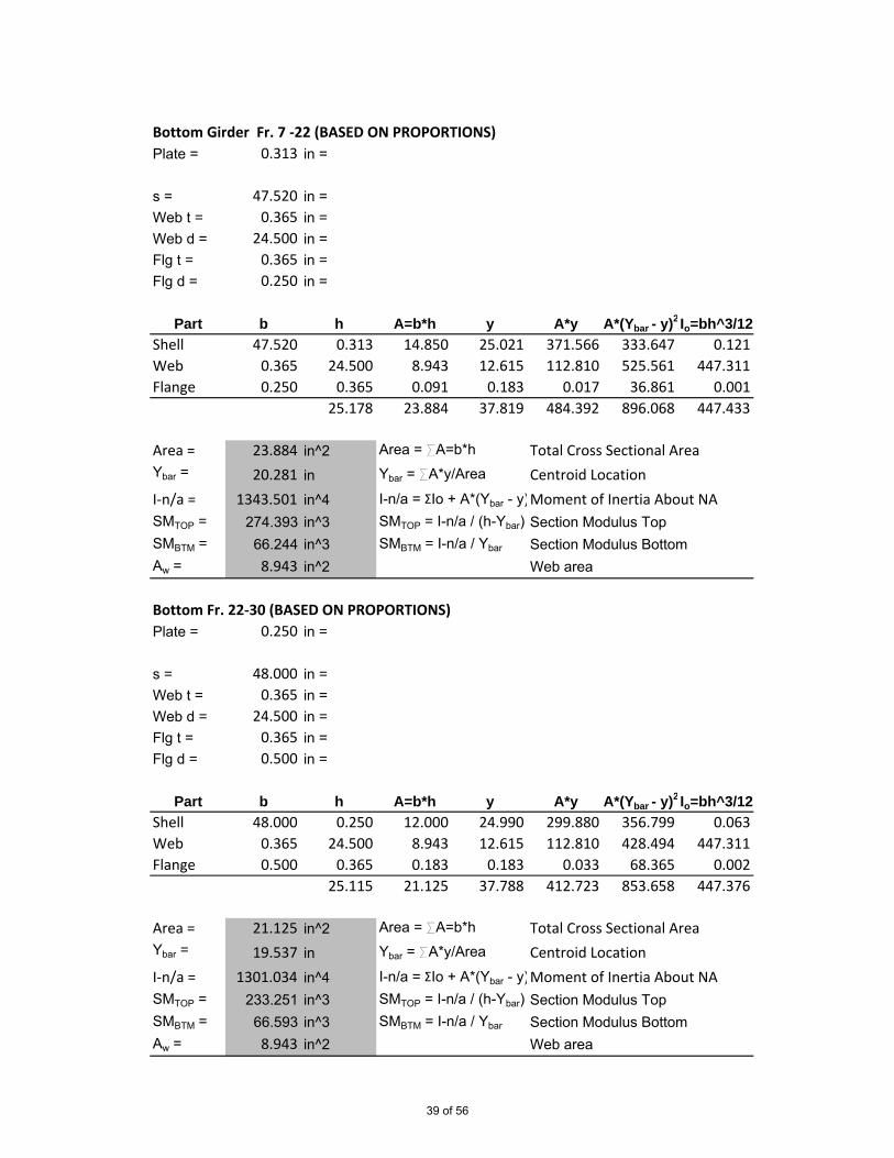
Bottom Girder Fr. 7 -22 (BASED ON PROPORTIONS)Plate = 0.313 in =
s = 47.520 in =Web t = 0.365 in =Web d = 24.500 in =Flg t = 0.365 in =Flg d = 0.250 in =
Part b h A=b*h y A*y A*(Ybar - y)2 Io=bh^3/12Shell 47.520 0.313 14.850 25.021 371.566 333.647 0.121Web 0.365 24.500 8.943 12.615 112.810 525.561 447.311Flange 0.250 0.365 0.091 0.183 0.017 36.861 0.001
25.178 23.884 37.819 484.392 896.068 447.433
Area = 23.884 in^2 Area = SA=b*h Total Cross Sectional AreaYbar = 20.281 in Ybar = SA*y/Area Centroid LocationI-n/a = 1343.501 in^4 I-n/a = ΣIo + A*(Ybar - y)2Moment of Inertia About NASMTOP = 274.393 in^3 SMTOP = I-n/a / (h-Ybar) Section Modulus TopSMBTM = 66.244 in^3 SMBTM = I-n/a / Ybar Section Modulus BottomAw = 8.943 in^2 Web area
Bottom Fr. 22-30 (BASED ON PROPORTIONS)Plate = 0.250 in =
s = 48.000 in =Web t = 0.365 in =Web d = 24.500 in =Flg t = 0.365 in =Flg d = 0.500 in =
Part b h A=b*h y A*y A*(Ybar - y)2 Io=bh^3/12Shell 48.000 0.250 12.000 24.990 299.880 356.799 0.063Web 0.365 24.500 8.943 12.615 112.810 428.494 447.311Flange 0.500 0.365 0.183 0.183 0.033 68.365 0.002
25.115 21.125 37.788 412.723 853.658 447.376
Area = 21.125 in^2 Area = SA=b*h Total Cross Sectional AreaYbar = 19.537 in Ybar = SA*y/Area Centroid LocationI-n/a = 1301.034 in^4 I-n/a = ΣIo + A*(Ybar - y)2Moment of Inertia About NASMTOP = 233.251 in^3 SMTOP = I-n/a / (h-Ybar) Section Modulus TopSMBTM = 66.593 in^3 SMBTM = I-n/a / Ybar Section Modulus BottomAw = 8.943 in^2 Web area
39 of 56

Bottom Girder Fr. 30-35 (BASED ON PROPORTIONS)Plate = 0.250 in =
s = 39.600 in =Web t = 0.230 in =Web d = 7.000 in =Flg t = 0.230 in =Flg d = 1.500 in =
Part b h A=b*h y A*y A*(Ybar - y)2 Io=bh^3/12Shell 39.600 0.250 9.900 7.355 72.815 4.893 0.052Web 0.230 7.000 1.610 3.730 6.005 13.746 6.574Flange 1.500 0.230 0.345 0.115 0.040 14.743 0.002
7.480 11.855 11.200 78.859 33.382 6.627
Area = 11.855 in^2 Area = SA=b*h Total Cross Sectional AreaYbar = 6.652 in Ybar = SA*y/Area Centroid LocationI-n/a = 40.009 in^4 I-n/a = ΣIo + A*(Ybar - y)2Moment of Inertia About NASMTOP = 48.320 in^3 SMTOP = I-n/a / (h-Ybar) Section Modulus TopSMBTM = 6.015 in^3 SMBTM = I-n/a / Ybar Section Modulus BottomAw = 1.610 in^2 Web area
Deck Girder Fr. 35-Transom (BASED ON PROPORTIONS)Plate = 0.250 in =
s = 27.720 in =Web t = 0.209 in =Web d = 4.900 in =Flg t = 0.209 in =Flg d = 1.500 in =
Part b h A=b*h y A*y A*(Ybar - y)2 Io=bh^3/12Shell 27.720 0.250 6.930 5.234 36.272 1.827 0.036Web 0.209 4.900 1.024 2.659 2.723 4.352 2.049Flange 1.500 0.209 0.314 0.105 0.033 6.680 0.001
5.359 8.268 7.998 39.027 12.859 2.086
Area = 8.268 in^2 Area = SA=b*h Total Cross Sectional AreaYbar = 4.721 in Ybar = SA*y/Area Centroid LocationI-n/a = 14.946 in^4 I-n/a = ΣIo + A*(Ybar - y)2Moment of Inertia About NASMTOP = 23.409 in^3 SMTOP = I-n/a / (h-Ybar) Section Modulus TopSMBTM = 3.166 in^3 SMBTM = I-n/a / Ybar Section Modulus BottomAw = 1.024 in^2 Web area
40 of 56
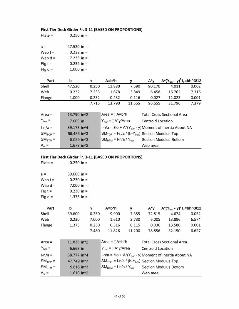
First Tier Deck Girder Fr. 3-11 (BASED ON PROPORTIONS)Plate = 0.250 in =
s = 47.520 in =Web t = 0.232 in =Web d = 7.233 in =Flg t = 0.232 in =Flg d = 1.000 in =
Part b h A=b*h y A*y A*(Ybar - y)2 Io=bh^3/12Shell 47.520 0.250 11.880 7.590 90.170 4.011 0.062Web 0.232 7.233 1.678 3.849 6.458 16.762 7.316Flange 1.000 0.232 0.232 0.116 0.027 11.023 0.001
7.715 13.790 11.555 96.655 31.796 7.379
Area = 13.790 in^2 Area = SA=b*h Total Cross Sectional AreaYbar = 7.009 in Ybar = SA*y/Area Centroid LocationI-n/a = 39.175 in^4 I-n/a = ΣIo + A*(Ybar - y)2Moment of Inertia About NASMTOP = 55.486 in^3 SMTOP = I-n/a / (h-Ybar) Section Modulus TopSMBTM = 5.589 in^3 SMBTM = I-n/a / Ybar Section Modulus BottomAw = 1.678 in^2 Web area
First Tier Deck Girder Fr. 3-11 (BASED ON PROPORTIONS)Plate = 0.250 in =
s = 39.600 in =Web t = 0.230 in =Web d = 7.000 in =Flg t = 0.230 in =Flg d = 1.375 in =
Part b h A=b*h y A*y A*(Ybar - y)2 Io=bh^3/12Shell 39.600 0.250 9.900 7.355 72.815 4.674 0.052Web 0.230 7.000 1.610 3.730 6.005 13.896 6.574Flange 1.375 0.230 0.316 0.115 0.036 13.580 0.001
7.480 11.826 11.200 78.856 32.150 6.627
Area = 11.826 in^2 Area = SA=b*h Total Cross Sectional AreaYbar = 6.668 in Ybar = SA*y/Area Centroid LocationI-n/a = 38.777 in^4 I-n/a = ΣIo + A*(Ybar - y)2Moment of Inertia About NASMTOP = 47.749 in^3 SMTOP = I-n/a / (h-Ybar) Section Modulus TopSMBTM = 5.816 in^3 SMBTM = I-n/a / Ybar Section Modulus BottomAw = 1.610 in^2 Web area
41 of 56

Main Deck Girder Fr. 7 -22,Plate = 0.250 in =
s = 47.520 in =Web t = 0.375 in =Web d = 5.625 in =Flg t = 0.375 in =Flg d = 3.000 in =
Part b h A=b*h y A*y A*(Ybar - y)2 Io=bh^3/12Shell 47.520 0.250 11.880 6.125 72.765 8.622 0.062Web 0.375 5.625 2.109 3.188 6.724 9.175 5.562Flange 3.000 0.375 1.125 0.188 0.211 29.096 0.013
6.250 15.114 9.500 79.700 46.893 5.637
Area = 15.114 in^2 Area = SA=b*h Total Cross Sectional AreaYbar = 5.273 in Ybar = SA*y/Area Centroid LocationI-n/a = 52.530 in^4 I-n/a = ΣIo + A*(Ybar - y)2Moment of Inertia About Neutral AxisSMTOP = 53.772 in^3 SMTOP = I-n/a / (h-Ybar) Section Modulus TopSMBTM = 9.962 in^3 SMBTM = I-n/a / Ybar Section Modulus BottomAw = 2.109 in^2 Web area
Main Deck Girder Fr. 22 -30Plate = 0.250 in =
s = 31.680 in =Web t = 0.375 in =Web d = 5.625 in =Flg t = 0.375 in =Flg d = 3.000 in =
Part b h A=b*h y A*y A*(Ybar - y)2 Io=bh^3/12Shell 31.680 0.250 7.920 6.125 48.510 10.553 0.041Web 0.375 5.625 2.109 3.188 6.724 6.707 5.562Flange 3.000 0.375 1.125 0.188 0.211 25.738 0.013
6.250 11.154 9.500 55.445 42.999 5.616
Area = 11.154 in^2 Area = SA=b*h Total Cross Sectional AreaYbar = 4.971 in Ybar = SA*y/Area Centroid LocationI-n/a = 48.615 in^4 I-n/a = ΣIo + A*(Ybar - y)2Moment of Inertia About Neutral AxisSMTOP = 38.000 in^3 SMTOP = I-n/a / (h-Ybar) Section Modulus TopSMBTM = 9.780 in^3 SMBTM = I-n/a / Ybar Section Modulus BottomAw = 2.109 in^2 Web area
42 of 56

Main Deck Girder Fr. 30-35Plate = 0.250 in =
s = 39.600 in =Web t = 0.375 in =Web d = 5.625 in =Flg t = 0.375 in =Flg d = 3.000 in =
Part b h A=b*h y A*y A*(Ybar - y)2 Io=bh^3/12Shell 39.600 0.250 9.900 6.125 60.638 9.514 0.052Web 0.375 5.625 2.109 3.188 6.724 8.080 5.562Flange 3.000 0.375 1.125 0.188 0.211 27.645 0.013
6.250 13.134 9.500 67.572 45.240 5.627
Area = 13.134 in^2 Area = SA=b*h Total Cross Sectional AreaYbar = 5.145 in Ybar = SA*y/Area Centroid LocationI-n/a = 50.866 in^4 I-n/a = ΣIo + A*(Ybar - y)2Moment of Inertia About Neutral AxisSMTOP = 46.019 in^3 SMTOP = I-n/a / (h-Ybar) Section Modulus TopSMBTM = 9.887 in^3 SMBTM = I-n/a / Ybar Section Modulus BottomAw = 2.109 in^2 Web area
Main Deck Girder Fr. 35 -TransomPlate = 0.250 in =
s = 27.720 in =Web t = 0.375 in =Web d = 5.625 in =Flg t = 0.375 in =Flg d = 3.000 in =
Part b h A=b*h y A*y A*(Ybar - y)2 Io=bh^3/12Shell 27.720 0.250 6.930 6.125 42.446 11.121 0.036Web 0.375 5.625 2.109 3.188 6.724 5.888 5.562Flange 3.000 0.375 1.125 0.188 0.211 24.543 0.013
6.250 10.164 9.500 49.381 41.551 5.611
Area = 10.164 in^2 Area = SA=b*h Total Cross Sectional AreaYbar = 4.858 in Ybar = SA*y/Area Centroid LocationI-n/a = 47.162 in^4 I-n/a = ΣIo + A*(Ybar - y)2Moment of Inertia About Neutral AxisSMTOP = 33.886 in^3 SMTOP = I-n/a / (h-Ybar) Section Modulus TopSMBTM = 9.708 in^3 SMBTM = I-n/a / Ybar Section Modulus BottomAw = 2.109 in^2 Web area
43 of 56
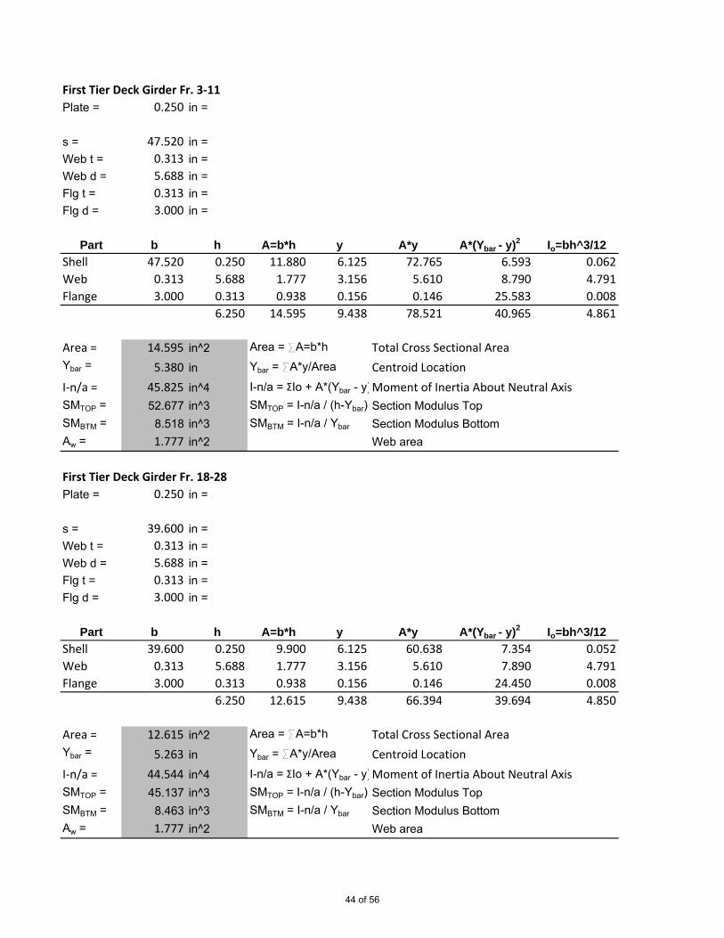
First Tier Deck Girder Fr. 3-11Plate = 0.250 in =
s = 47.520 in =Web t = 0.313 in =Web d = 5.688 in =Flg t = 0.313 in =Flg d = 3.000 in =
Part b h A=b*h y A*y A*(Ybar - y)2 Io=bh^3/12Shell 47.520 0.250 11.880 6.125 72.765 6.593 0.062Web 0.313 5.688 1.777 3.156 5.610 8.790 4.791Flange 3.000 0.313 0.938 0.156 0.146 25.583 0.008
6.250 14.595 9.438 78.521 40.965 4.861
Area = 14.595 in^2 Area = SA=b*h Total Cross Sectional AreaYbar = 5.380 in Ybar = SA*y/Area Centroid LocationI-n/a = 45.825 in^4 I-n/a = ΣIo + A*(Ybar - y)2Moment of Inertia About Neutral AxisSMTOP = 52.677 in^3 SMTOP = I-n/a / (h-Ybar) Section Modulus TopSMBTM = 8.518 in^3 SMBTM = I-n/a / Ybar Section Modulus BottomAw = 1.777 in^2 Web area
First Tier Deck Girder Fr. 18-28Plate = 0.250 in =
s = 39.600 in =Web t = 0.313 in =Web d = 5.688 in =Flg t = 0.313 in =Flg d = 3.000 in =
Part b h A=b*h y A*y A*(Ybar - y)2 Io=bh^3/12Shell 39.600 0.250 9.900 6.125 60.638 7.354 0.052Web 0.313 5.688 1.777 3.156 5.610 7.890 4.791Flange 3.000 0.313 0.938 0.156 0.146 24.450 0.008
6.250 12.615 9.438 66.394 39.694 4.850
Area = 12.615 in^2 Area = SA=b*h Total Cross Sectional AreaYbar = 5.263 in Ybar = SA*y/Area Centroid LocationI-n/a = 44.544 in^4 I-n/a = ΣIo + A*(Ybar - y)2Moment of Inertia About Neutral AxisSMTOP = 45.137 in^3 SMTOP = I-n/a / (h-Ybar) Section Modulus TopSMBTM = 8.463 in^3 SMBTM = I-n/a / Ybar Section Modulus BottomAw = 1.777 in^2 Web area
44 of 56

1 A-frame longitudinal supportPlate = 1.000 in =
s = 36.000 in =Web t = 0.500 in =Web d = 7.500 in =Flg t = 0.500 in =Flg d = 6.000 in =
Part b h A=b*h y A*y A*(Ybar - y)2 Io=bh^3/12Shell 36.000 1.000 36.000 8.500 306.000 32.610 3.000Web 0.500 7.500 3.750 4.250 15.938 40.794 17.578Flange 6.000 0.500 3.000 0.250 0.750 159.793 0.063
9.000 42.750 13.000 322.688 233.197 20.641
Area = 42.750 in^2 Area = SA=b*h Total Cross Sectional AreaYbar = 7.548 in Ybar = SA*y/Area Centroid LocationI-n/a = 253.838 in^4 I-n/a = ΣIo + A*(Ybar - y)2Moment of Inertia About Neutral AxisSMTOP = 174.849 in^3 SMTOP = I-n/a / (h-Ybar) Section Modulus TopSMBTM = 33.629 in^3 SMBTM = I-n/a / Ybar Section Modulus BottomAw = 3.750 in^2 Web area
45 of 56
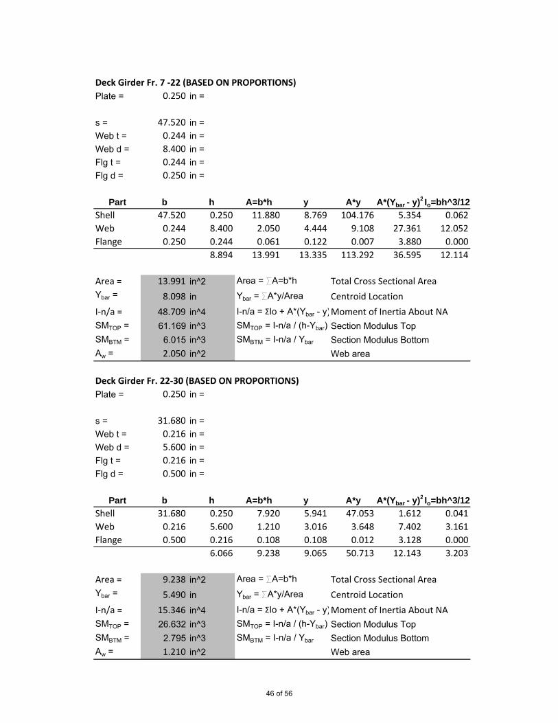
Deck Girder Fr. 7 -22 (BASED ON PROPORTIONS)Plate = 0.250 in =
s = 47.520 in =Web t = 0.244 in =Web d = 8.400 in =Flg t = 0.244 in =Flg d = 0.250 in =
Part b h A=b*h y A*y A*(Ybar - y)2 Io=bh^3/12Shell 47.520 0.250 11.880 8.769 104.176 5.354 0.062Web 0.244 8.400 2.050 4.444 9.108 27.361 12.052Flange 0.250 0.244 0.061 0.122 0.007 3.880 0.000
8.894 13.991 13.335 113.292 36.595 12.114
Area = 13.991 in^2 Area = SA=b*h Total Cross Sectional AreaYbar = 8.098 in Ybar = SA*y/Area Centroid LocationI-n/a = 48.709 in^4 I-n/a = ΣIo + A*(Ybar - y)2Moment of Inertia About NASMTOP = 61.169 in^3 SMTOP = I-n/a / (h-Ybar) Section Modulus TopSMBTM = 6.015 in^3 SMBTM = I-n/a / Ybar Section Modulus BottomAw = 2.050 in^2 Web area
Deck Girder Fr. 22-30 (BASED ON PROPORTIONS)Plate = 0.250 in =
s = 31.680 in =Web t = 0.216 in =Web d = 5.600 in =Flg t = 0.216 in =Flg d = 0.500 in =
Part b h A=b*h y A*y A*(Ybar - y)2 Io=bh^3/12Shell 31.680 0.250 7.920 5.941 47.053 1.612 0.041Web 0.216 5.600 1.210 3.016 3.648 7.402 3.161Flange 0.500 0.216 0.108 0.108 0.012 3.128 0.000
6.066 9.238 9.065 50.713 12.143 3.203
Area = 9.238 in^2 Area = SA=b*h Total Cross Sectional AreaYbar = 5.490 in Ybar = SA*y/Area Centroid LocationI-n/a = 15.346 in^4 I-n/a = ΣIo + A*(Ybar - y)2Moment of Inertia About NASMTOP = 26.632 in^3 SMTOP = I-n/a / (h-Ybar) Section Modulus TopSMBTM = 2.795 in^3 SMBTM = I-n/a / Ybar Section Modulus BottomAw = 1.210 in^2 Web area
46 of 56

Deck Girder Fr. 30-35 (BASED ON PROPORTIONS)Plate = 0.250 in =
s = 39.600 in =Web t = 0.230 in =Web d = 7.000 in =Flg t = 0.230 in =Flg d = 1.500 in =
Part b h A=b*h y A*y A*(Ybar - y)2 Io=bh^3/12Shell 39.600 0.250 9.900 7.355 72.815 4.893 0.052Web 0.230 7.000 1.610 3.730 6.005 13.746 6.574Flange 1.500 0.230 0.345 0.115 0.040 14.743 0.002
7.480 11.855 11.200 78.859 33.382 6.627
Area = 11.855 in^2 Area = SA=b*h Total Cross Sectional AreaYbar = 6.652 in Ybar = SA*y/Area Centroid LocationI-n/a = 40.009 in^4 I-n/a = ΣIo + A*(Ybar - y)2Moment of Inertia About NASMTOP = 48.320 in^3 SMTOP = I-n/a / (h-Ybar) Section Modulus TopSMBTM = 6.015 in^3 SMBTM = I-n/a / Ybar Section Modulus BottomAw = 1.610 in^2 Web area
Deck Girder Fr. 35-Transom (BASED ON PROPORTIONS)Plate = 0.250 in =
s = 27.720 in =Web t = 0.209 in =Web d = 4.900 in =Flg t = 0.209 in =Flg d = 1.500 in =
Part b h A=b*h y A*y A*(Ybar - y)2 Io=bh^3/12Shell 27.720 0.250 6.930 5.234 36.272 1.827 0.036Web 0.209 4.900 1.024 2.659 2.723 4.352 2.049Flange 1.500 0.209 0.314 0.105 0.033 6.680 0.001
5.359 8.268 7.998 39.027 12.859 2.086
Area = 8.268 in^2 Area = SA=b*h Total Cross Sectional AreaYbar = 4.721 in Ybar = SA*y/Area Centroid LocationI-n/a = 14.946 in^4 I-n/a = ΣIo + A*(Ybar - y)2Moment of Inertia About NASMTOP = 23.409 in^3 SMTOP = I-n/a / (h-Ybar) Section Modulus TopSMBTM = 3.166 in^3 SMBTM = I-n/a / Ybar Section Modulus BottomAw = 1.024 in^2 Web area
47 of 56

First Tier Deck Girder Fr. 3-11 (BASED ON PROPORTIONS)Plate = 0.250 in =
s = 47.520 in =Web t = 0.232 in =Web d = 7.233 in =Flg t = 0.232 in =Flg d = 1.000 in =
Part b h A=b*h y A*y A*(Ybar - y)2 Io=bh^3/12Shell 47.520 0.250 11.880 7.590 90.170 4.011 0.062Web 0.232 7.233 1.678 3.849 6.458 16.762 7.316Flange 1.000 0.232 0.232 0.116 0.027 11.023 0.001
7.715 13.790 11.555 96.655 31.796 7.379
Area = 13.790 in^2 Area = SA=b*h Total Cross Sectional AreaYbar = 7.009 in Ybar = SA*y/Area Centroid LocationI-n/a = 39.175 in^4 I-n/a = ΣIo + A*(Ybar - y)2Moment of Inertia About NASMTOP = 55.486 in^3 SMTOP = I-n/a / (h-Ybar) Section Modulus TopSMBTM = 5.589 in^3 SMBTM = I-n/a / Ybar Section Modulus BottomAw = 1.678 in^2 Web area
First Tier Deck Girder Fr. 3-11 (BASED ON PROPORTIONS)Plate = 0.250 in =
s = 39.600 in =Web t = 0.230 in =Web d = 7.000 in =Flg t = 0.230 in =Flg d = 1.375 in =
Part b h A=b*h y A*y A*(Ybar - y)2 Io=bh^3/12Shell 39.600 0.250 9.900 7.355 72.815 4.674 0.052Web 0.230 7.000 1.610 3.730 6.005 13.896 6.574Flange 1.375 0.230 0.316 0.115 0.036 13.580 0.001
7.480 11.826 11.200 78.856 32.150 6.627
Area = 11.826 in^2 Area = SA=b*h Total Cross Sectional AreaYbar = 6.668 in Ybar = SA*y/Area Centroid LocationI-n/a = 38.777 in^4 I-n/a = ΣIo + A*(Ybar - y)2Moment of Inertia About NASMTOP = 47.749 in^3 SMTOP = I-n/a / (h-Ybar) Section Modulus TopSMBTM = 5.816 in^3 SMBTM = I-n/a / Ybar Section Modulus BottomAw = 1.610 in^2 Web area
48 of 56
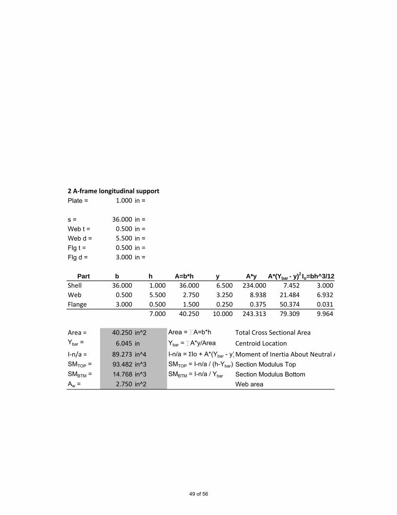
2 A-frame longitudinal supportPlate = 1.000 in =
s = 36.000 in =Web t = 0.500 in =Web d = 5.500 in =Flg t = 0.500 in =Flg d = 3.000 in =
Part b h A=b*h y A*y A*(Ybar - y)2 Io=bh^3/12Shell 36.000 1.000 36.000 6.500 234.000 7.452 3.000Web 0.500 5.500 2.750 3.250 8.938 21.484 6.932Flange 3.000 0.500 1.500 0.250 0.375 50.374 0.031
7.000 40.250 10.000 243.313 79.309 9.964
Area = 40.250 in^2 Area = SA=b*h Total Cross Sectional AreaYbar = 6.045 in Ybar = SA*y/Area Centroid LocationI-n/a = 89.273 in^4 I-n/a = ΣIo + A*(Ybar - y)2Moment of Inertia About Neutral AxisSMTOP = 93.482 in^3 SMTOP = I-n/a / (h-Ybar) Section Modulus TopSMBTM = 14.768 in^3 SMBTM = I-n/a / Ybar Section Modulus BottomAw = 2.750 in^2 Web area
49 of 56

Main Deck Transverse Fr. 12 and 16.5Plate = 0.250 in =
s = 47.520 in =Web t = 0.500 in =Web d = 5.500 in =Flg t = 0.500 in =Flg d = 4.000 in =
Part b h A=b*h y A*y A*(Ybar - y)2 Io=bh^3/12Shell 47.520 0.250 11.880 6.125 72.765 16.597 0.062Web 0.500 5.500 2.750 3.250 8.938 7.882 6.932Flange 4.000 0.500 2.000 0.250 0.500 44.049 0.042
6.250 16.630 9.625 82.203 68.529 7.036
Area = 16.630 in^2 Area = SA=b*h Total Cross Sectional AreaYbar = 4.943 in Ybar = SA*y/Area Centroid LocationI-n/a = 75.564 in^4 I-n/a = ΣIo + A*(Ybar - y)2Moment of Inertia About Neutral AxisSMTOP = 57.816 in^3 SMTOP = I-n/a / (h-Ybar) Section Modulus TopSMBTM = 15.287 in^3 SMBTM = I-n/a / Ybar Section Modulus BottomAw = 2.750 in^2 Web area
Main Deck Transverse Fr. 26Plate = 0.250 in =
s = 35.640 in =Web t = 0.250 in =Web d = 5.750 in =Flg t = 0.250 in =Flg d = 3.000 in =
Part b h A=b*h y A*y A*(Ybar - y)2 Io=bh^3/12Shell 35.640 0.250 8.910 6.125 54.574 5.619 0.046Web 0.250 5.750 1.438 3.125 4.492 6.995 3.961Flange 3.000 0.250 0.750 0.125 0.094 20.326 0.004
6.250 11.098 9.375 59.160 32.940 4.011
Area = 11.098 in^2 Area = SA=b*h Total Cross Sectional AreaYbar = 5.331 in Ybar = SA*y/Area Centroid LocationI-n/a = 36.950 in^4 I-n/a = ΣIo + A*(Ybar - y)2Moment of Inertia About Neutral AxisSMTOP = 40.203 in^3 SMTOP = I-n/a / (h-Ybar) Section Modulus TopSMBTM = 6.931 in^3 SMBTM = I-n/a / Ybar Section Modulus BottomAw = 1.438 in^2 Web area
50 of 56

Main Deck Transverse Fr. 12 and 16.5 (BASED ON PROPORTIONS)Plate = 0.250 in =
s = 47.520 in =Web t = 0.244 in =Web d = 8.400 in =Flg t = 0.244 in =Flg d = 2.000 in =
Part b h A=b*h y A*y A*(Ybar - y)2 Io=bh^3/12Shell 47.520 0.250 11.880 8.769 104.176 9.784 0.062Web 0.244 8.400 2.050 4.444 9.108 23.938 12.052Flange 2.000 0.244 0.488 0.122 0.060 29.231 0.002
8.894 14.418 13.335 113.344 62.953 12.116
Area = 14.418 in^2 Area = SA=b*h Total Cross Sectional AreaYbar = 7.861 in Ybar = SA*y/Area Centroid LocationI-n/a = 75.069 in^4 I-n/a = ΣIo + A*(Ybar - y)2Moment of Inertia About NASMTOP = 72.705 in^3 SMTOP = I-n/a / (h-Ybar) Section Modulus TopSMBTM = 9.549 in^3 SMBTM = I-n/a / Ybar Section Modulus BottomAw = 2.050 in^2 Web area
Main Deck Transverse Fr.26 (BASED ON PROPORTIONS)Plate = 0.250 in =
s = 35.640 in =Web t = 0.223 in =Web d = 6.300 in =Flg t = 0.223 in =Flg d = 1.250 in =
Part b h A=b*h y A*y A*(Ybar - y)2 Io=bh^3/12Shell 35.640 0.250 8.910 6.648 59.234 3.275 0.046Web 0.223 6.300 1.405 3.373 4.739 10.006 4.647Flange 1.250 0.223 0.279 0.112 0.031 9.803 0.001
6.773 10.594 10.133 64.003 23.084 4.694
Area = 10.594 in^2 Area = SA=b*h Total Cross Sectional AreaYbar = 6.042 in Ybar = SA*y/Area Centroid LocationI-n/a = 27.778 in^4 I-n/a = ΣIo + A*(Ybar - y)2Moment of Inertia About NASMTOP = 37.984 in^3 SMTOP = I-n/a / (h-Ybar) Section Modulus TopSMBTM = 4.598 in^3 SMBTM = I-n/a / Ybar Section Modulus BottomAw = 1.405 in^2 Web area
51 of 56
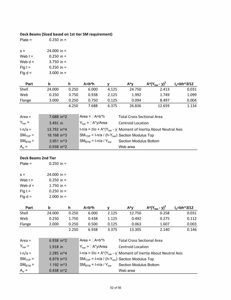
Deck Beams (Sized based on 1st tier SM requirement)Plate = 0.250 in =
s = 24.000 in =Web t = 0.250 in =Web d = 3.750 in =Flg t = 0.250 in =Flg d = 3.000 in =
Part b h A=b*h y A*y A*(Ybar - y)2 Io=bh^3/12Shell 24.000 0.250 6.000 4.125 24.750 2.413 0.031Web 0.250 3.750 0.938 2.125 1.992 1.749 1.099Flange 3.000 0.250 0.750 0.125 0.094 8.497 0.004
4.250 7.688 6.375 26.836 12.659 1.134
Area = 7.688 in^2 Area = SA=b*h Total Cross Sectional AreaYbar = 3.491 in Ybar = SA*y/Area Centroid LocationI-n/a = 13.792 in^4 I-n/a = ΣIo + A*(Ybar - y)2Moment of Inertia About Neutral AxisSMTOP = 18.168 in^3 SMTOP = I-n/a / (h-Ybar) Section Modulus TopSMBTM = 3.951 in^3 SMBTM = I-n/a / Ybar Section Modulus BottomAw = 0.938 in^2 Web area
Deck Beams 2nd TierPlate = 0.250 in =
s = 24.000 in =Web t = 0.250 in =Web d = 1.750 in =Flg t = 0.250 in =Flg d = 2.000 in =
Part b h A=b*h y A*y A*(Ybar - y)2 Io=bh^3/12Shell 24.000 0.250 6.000 2.125 12.750 0.258 0.031Web 0.250 1.750 0.438 1.125 0.492 0.275 0.112Flange 2.000 0.250 0.500 0.125 0.063 1.607 0.003
2.250 6.938 3.375 13.305 2.140 0.146
Area = 6.938 in^2 Area = SA=b*h Total Cross Sectional AreaYbar = 1.918 in Ybar = SA*y/Area Centroid LocationI-n/a = 2.285 in^4 I-n/a = ΣIo + A*(Ybar - y)2Moment of Inertia About Neutral AxisSMTOP = 6.879 in^3 SMTOP = I-n/a / (h-Ybar) Section Modulus TopSMBTM = 1.192 in^3 SMBTM = I-n/a / Ybar Section Modulus BottomAw = 0.438 in^2 Web area
52 of 56
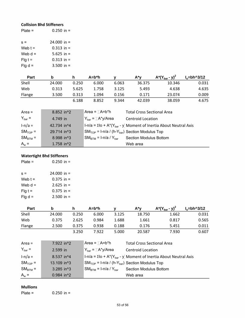
Collision Bhd StiffenersPlate = 0.250 in =
s = 24.000 in =Web t = 0.313 in =Web d = 5.625 in =Flg t = 0.313 in =Flg d = 3.500 in =
Part b h A=b*h y A*y A*(Ybar - y)2 Io=bh^3/12Shell 24.000 0.250 6.000 6.063 36.375 10.346 0.031Web 0.313 5.625 1.758 3.125 5.493 4.638 4.635Flange 3.500 0.313 1.094 0.156 0.171 23.074 0.009
6.188 8.852 9.344 42.039 38.059 4.675
Area = 8.852 in^2 Area = SA=b*h Total Cross Sectional AreaYbar = 4.749 in Ybar = SA*y/Area Centroid LocationI-n/a = 42.734 in^4 I-n/a = ΣIo + A*(Ybar - y)2Moment of Inertia About Neutral AxisSMTOP = 29.714 in^3 SMTOP = I-n/a / (h-Ybar) Section Modulus TopSMBTM = 8.998 in^3 SMBTM = I-n/a / Ybar Section Modulus BottomAw = 1.758 in^2 Web area
Watertight Bhd StiffenersPlate = 0.250 in =
s = 24.000 in =Web t = 0.375 in =Web d = 2.625 in =Flg t = 0.375 in =Flg d = 2.500 in =
Part b h A=b*h y A*y A*(Ybar - y)2 Io=bh^3/12Shell 24.000 0.250 6.000 3.125 18.750 1.662 0.031Web 0.375 2.625 0.984 1.688 1.661 0.817 0.565Flange 2.500 0.375 0.938 0.188 0.176 5.451 0.011
3.250 7.922 5.000 20.587 7.930 0.607
Area = 7.922 in^2 Area = SA=b*h Total Cross Sectional AreaYbar = 2.599 in Ybar = SA*y/Area Centroid LocationI-n/a = 8.537 in^4 I-n/a = ΣIo + A*(Ybar - y)2Moment of Inertia About Neutral AxisSMTOP = 13.109 in^3 SMTOP = I-n/a / (h-Ybar) Section Modulus TopSMBTM = 3.285 in^3 SMBTM = I-n/a / Ybar Section Modulus BottomAw = 0.984 in^2 Web area
MullionsPlate = 0.250 in =
53 of 56
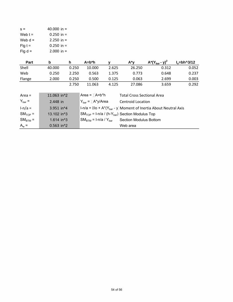
s = 40.000 in =Web t = 0.250 in =Web d = 2.250 in =Flg t = 0.250 in =Flg d = 2.000 in =
Part b h A=b*h y A*y A*(Ybar - y)2 Io=bh^3/12Shell 40.000 0.250 10.000 2.625 26.250 0.312 0.052Web 0.250 2.250 0.563 1.375 0.773 0.648 0.237Flange 2.000 0.250 0.500 0.125 0.063 2.699 0.003
2.750 11.063 4.125 27.086 3.659 0.292
Area = 11.063 in^2 Area = SA=b*h Total Cross Sectional AreaYbar = 2.448 in Ybar = SA*y/Area Centroid LocationI-n/a = 3.951 in^4 I-n/a = ΣIo + A*(Ybar - y)2Moment of Inertia About Neutral AxisSMTOP = 13.102 in^3 SMTOP = I-n/a / (h-Ybar) Section Modulus TopSMBTM = 1.614 in^3 SMBTM = I-n/a / Ybar Section Modulus BottomAw = 0.563 in^2 Web area
54 of 56

Side FramesPlate = 0.250 in =
s = 24.000 in =Web t = 0.250 in =Web d = 3.750 in =Flg t = 0.250 in =Flg d = 3.000 in =
Part b h A=b*h y A*y A*(Ybar - y)2 Io=bh^3/12Shell 24.000 0.250 6.000 4.125 24.750 2.413 0.031Web 0.250 3.750 0.938 2.125 1.992 1.749 1.099Flange 3.000 0.250 0.750 0.125 0.094 8.497 0.004
4.250 7.688 6.375 26.836 12.659 1.134
Area = 7.688 in^2 Area = SA=b*h Total Cross Sectional AreaYbar = 3.491 in Ybar = SA*y/Area Centroid LocationI-n/a = 13.792 in^4 I-n/a = ΣIo + A*(Ybar - y)2Moment of Inertia About Neutral AxisSMTOP = 18.168 in^3 SMTOP = I-n/a / (h-Ybar) Section Modulus TopSMBTM = 3.951 in^3 SMBTM = I-n/a / Ybar Section Modulus BottomAw = 0.938 in^2 Web area
Bottom FramesPlate = 0.250 in =
s = 24.000 in =Web t = 0.250 in =Web d = 3.750 in =Flg t = 0.250 in =Flg d = 3.000 in =
Part b h A=b*h y A*y A*(Ybar - y)2 Io=bh^3/12Shell 24.000 0.250 6.000 4.125 24.750 2.413 0.031Web 0.250 3.750 0.938 2.125 1.992 1.749 1.099Flange 3.000 0.250 0.750 0.125 0.094 8.497 0.004
4.250 7.688 6.375 26.836 12.659 1.134
Area = 7.688 in^2 Area = SA=b*h Total Cross Sectional AreaYbar = 3.491 in Ybar = SA*y/Area Centroid LocationI-n/a = 13.792 in^4 I-n/a = ΣIo + A*(Ybar - y)2Moment of Inertia About Neutral AxisSMTOP = 18.168 in^3 SMTOP = I-n/a / (h-Ybar) Section Modulus TopSMBTM = 3.951 in^3 SMBTM = I-n/a / Ybar Section Modulus BottomAw = 0.938 in^2 Web area
55 of 56
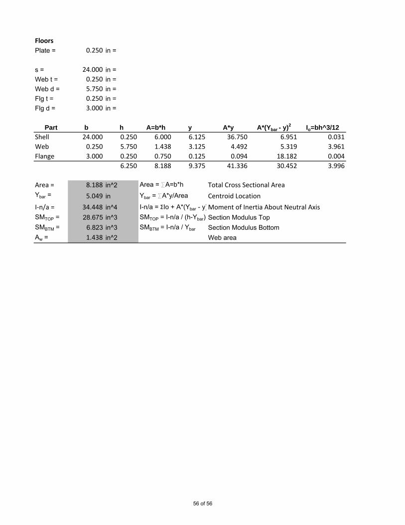
FloorsPlate = 0.250 in =
s = 24.000 in =Web t = 0.250 in =Web d = 5.750 in =Flg t = 0.250 in =Flg d = 3.000 in =
Part b h A=b*h y A*y A*(Ybar - y)2 Io=bh^3/12Shell 24.000 0.250 6.000 6.125 36.750 6.951 0.031Web 0.250 5.750 1.438 3.125 4.492 5.319 3.961Flange 3.000 0.250 0.750 0.125 0.094 18.182 0.004
6.250 8.188 9.375 41.336 30.452 3.996
Area = 8.188 in^2 Area = SA=b*h Total Cross Sectional AreaYbar = 5.049 in Ybar = SA*y/Area Centroid LocationI-n/a = 34.448 in^4 I-n/a = ΣIo + A*(Ybar - y)2Moment of Inertia About Neutral AxisSMTOP = 28.675 in^3 SMTOP = I-n/a / (h-Ybar) Section Modulus TopSMBTM = 6.823 in^3 SMBTM = I-n/a / Ybar Section Modulus BottomAw = 1.438 in^2 Web area
56 of 56

No.: By: Date:0 JET 25-Nov-15
DRAWN BY:JET
DATE:1-May-15
PROJECT: DWG. #: SHEET: REV.: SCALE:408-Research Vessel 408-810-02 1 of 6 0 N/A
FIOTITLE:
WELDING SCHEDULE
15515 Starling Crossing Dr
Lithia, FL 33547
(813) 654-9800
FOR:
REVISIONS:
Initial Issue
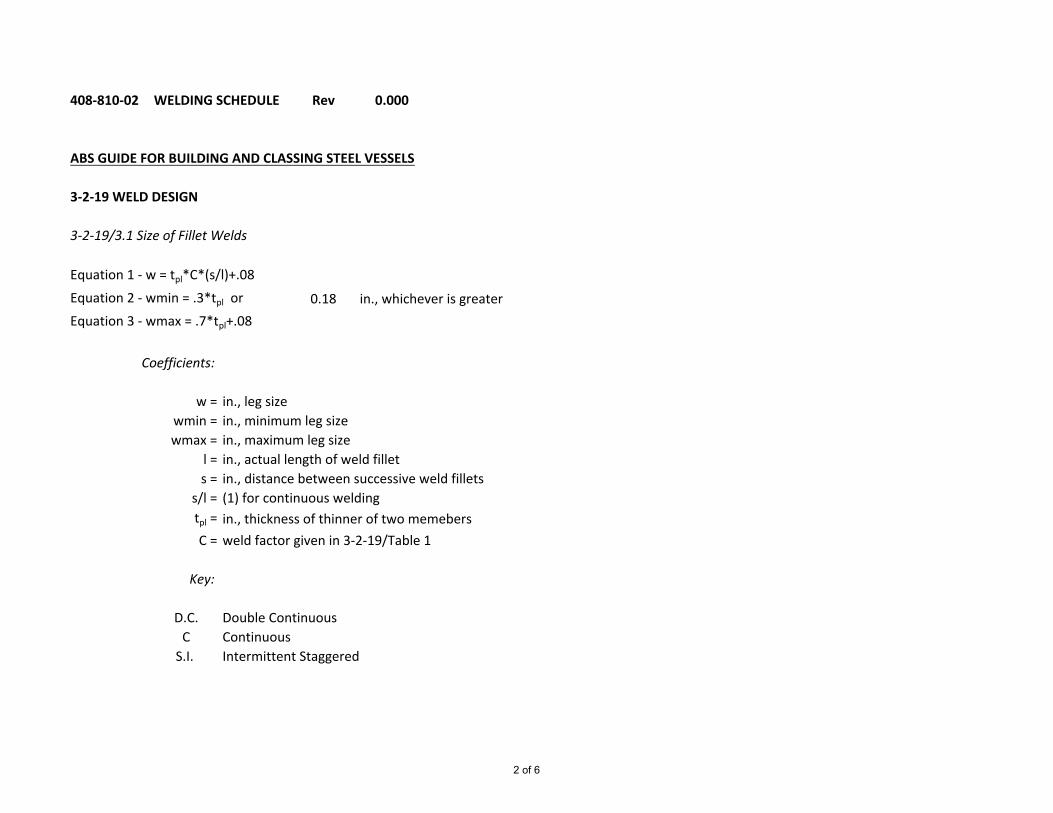
408-810-02 WELDING SCHEDULE Rev 0.000
ABS GUIDE FOR BUILDING AND CLASSING STEEL VESSELS
3-2-19 WELD DESIGN
3-2-19/3.1 Size of Fillet Welds
Equation 1 - w = tpl*C*(s/l)+.08Equation 2 - wmin = .3*tpl or 0.18 in., whichever is greaterEquation 3 - wmax = .7*tpl+.08
Coefficients:
w = in., leg sizewmin = in., minimum leg sizewmax = in., maximum leg size
l = in., actual length of weld fillets = in., distance between successive weld fillets
s/l = (1) for continuous weldingtpl = in., thickness of thinner of two memebersC = weld factor given in 3-2-19/Table 1
Key:
D.C. Double ContinuousC Continuous
S.I. Intermittent Staggered
2 of 6

tpl C s l w w min w min w max Use Type(calc.) (use)
Decks
Main deck 0.250 0.420 1.000 1.000 0.185 0.075 0.180 0.255 3/16" D.C.01 deck 0.250 0.420 1.000 1.000 0.185 0.075 0.180 0.255 3/16" D.C.Pilothouse top 0.188 0.350 1.000 1.000 0.146 0.056 0.180 0.211 3/16" D.C.
Bulkheads
Watertight 0.25 0.350 1.000 1.000 0.168 0.075 0.180 0.255 3/16" D.C.Non-tight
Swash Bulkheads 0.25 0.200 9.000 3.000 0.230 0.075 0.180 0.255 1/4" S.I.
Bottom Floors
To ShellAft peak below WL 0.250 0.250 1.000 1.000 0.143 0.075 0.180 0.255 3/16" D.C.Machinery Space 0.25 0.200 1.000 1.000 0.130 0.075 0.180 0.255 3/16" D.C.Flat of Bottom FWD 0.250 0.150 9.000 3.000 0.193 0.075 0.180 0.255 1/4" S.I.
To Side GirderIWO engine 0.25 0.300 1.000 1.000 0.155 0.075 0.180 0.255 3/16" D.C.Transverse Framing 0.25 0.300 1.000 1.000 0.155 0.075 0.180 0.255 3/16" D.C.Long. Framing 0.250 0.170 9.000 3.000 0.208 0.075 0.180 0.255 1/4" S.I.
To Side Shell 0.25 0.350 1.000 1.000 0.168 0.075 0.180 0.255 3/16" D.C.
Bottom Girders
Side GirderTo Floors IWO BHDS 0.25 0.350 1.000 1.000 0.168 0.075 0.180 0.255 3/16" D.C.
Member
3 of 6
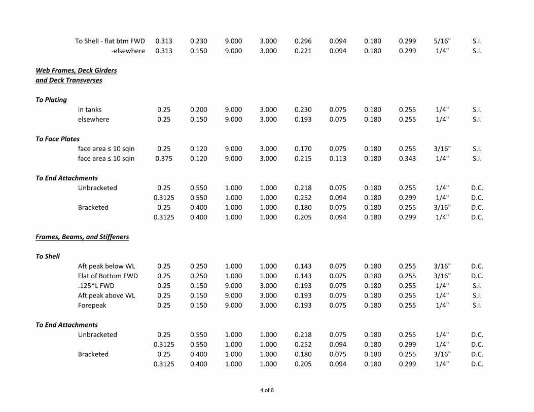
To Shell - flat btm FWD 0.313 0.230 9.000 3.000 0.296 0.094 0.180 0.299 5/16" S.I.-elsewhere 0.313 0.150 9.000 3.000 0.221 0.094 0.180 0.299 1/4" S.I.
Web Frames, Deck Girdersand Deck Transverses
To Platingin tanks 0.25 0.200 9.000 3.000 0.230 0.075 0.180 0.255 1/4" S.I.elsewhere 0.25 0.150 9.000 3.000 0.193 0.075 0.180 0.255 1/4" S.I.
To Face Platesface area ≤ 10 sqin 0.25 0.120 9.000 3.000 0.170 0.075 0.180 0.255 3/16" S.I.face area ≤ 10 sqin 0.375 0.120 9.000 3.000 0.215 0.113 0.180 0.343 1/4" S.I.
To End AttachmentsUnbracketed 0.25 0.550 1.000 1.000 0.218 0.075 0.180 0.255 1/4" D.C.
0.3125 0.550 1.000 1.000 0.252 0.094 0.180 0.299 1/4" D.C.Bracketed 0.25 0.400 1.000 1.000 0.180 0.075 0.180 0.255 3/16" D.C.
0.3125 0.400 1.000 1.000 0.205 0.094 0.180 0.299 1/4" D.C.
Frames, Beams, and Stiffeners
To ShellAft peak below WL 0.25 0.250 1.000 1.000 0.143 0.075 0.180 0.255 3/16" D.C.Flat of Bottom FWD 0.25 0.250 1.000 1.000 0.143 0.075 0.180 0.255 3/16" D.C..125*L FWD 0.25 0.150 9.000 3.000 0.193 0.075 0.180 0.255 1/4" S.I.Aft peak above WL 0.25 0.150 9.000 3.000 0.193 0.075 0.180 0.255 1/4" S.I.Forepeak 0.25 0.150 9.000 3.000 0.193 0.075 0.180 0.255 1/4" S.I.
To End AttachmentsUnbracketed 0.25 0.550 1.000 1.000 0.218 0.075 0.180 0.255 1/4" D.C.
0.3125 0.550 1.000 1.000 0.252 0.094 0.180 0.299 1/4" D.C.Bracketed 0.25 0.400 1.000 1.000 0.180 0.075 0.180 0.255 3/16" D.C.
0.3125 0.400 1.000 1.000 0.205 0.094 0.180 0.299 1/4" D.C.
4 of 6

Hatch Covers
Oiltight Joints 0.25 0.400 1.000 1.000 0.180 0.075 0.180 0.255 3/16" D.C.
Watertight JointsOutside 0.25 0.400 1.000 1.000 0.180 0.075 0.180 0.255 3/16" CInside 0.25 0.150 9.000 3.000 0.193 0.075 0.180 0.255 1/4" S.I.
Stiffeners and Web to SidePlating or other Stiffeners
Unbracketed 0.25 0.450 1.000 1.000 0.193 0.075 0.180 0.255 1/4" D.C.0.3125 0.450 1.000 1.000 0.221 0.094 0.180 0.299 1/4" D.C.
Bracketed 0.25 0.350 1.000 1.000 0.168 0.075 0.180 0.255 3/16" D.C.0.3125 0.350 1.000 1.000 0.189 0.094 0.180 0.299 3/16" D.C.
Hatch Coamings and Ventilators
To DeckAt Hatch Corner 0.25 0.450 1.000 1.000 0.193 0.075 0.180 0.255 1/4" D.C.Elsewhere 0.25 0.250 1.000 1.000 0.143 0.075 0.180 0.255 3/16" D.C.
Foundations
Main Engine and Major 0.25 0.400 1.000 1.000 0.180 0.075 0.180 0.255 3/16" D.C.Auxiliaries 0.3125 0.400 1.000 1.000 0.205 0.094 0.180 0.299 1/4" D.C.
0.375 0.400 1.000 1.000 0.230 0.113 0.180 0.343 1/4" D.C.
Rudders - Diaphragms
To Side PlatingIWO Rudder axis 0.3125 0.450 1.000 1.000 0.221 0.094 0.180 0.299 1/4" D.C.Elsewhere 0.3125 0.200 9.000 3.000 0.268 0.094 0.180 0.299 5/16" S.I.Slot Welds 0.25 0.450 1.000 1.000 0.193 0.075 0.180 0.255 3/16" D.C.
5 of 6

Notes for Buttweld Edge Preparation
Up to 3/16" butt joint - Square-butt welded3/16" to 5/8" butt joint - Single-Vee 60 deg. with 0"- 3/16" root gap, 1/8" landOver 5/8" butt joint - Double-Vee 60 deg. with 0"-3/16" root gap, 1/8" land
**Note: Bevel 3:1 when thickness varies more than 1/8".
6 of 6

B
A
2 134
B
A
2 134
PROPRIETARY INFORMATION THIS DOCUMENT IS PROPRIETARY. NO DATA OR DESIGN SHALL BE COPIED, REPRODUCED, DISCLOSEDOR SUBMITTED TO ANY THIRD PARTY OR USED FOR CONSTRUCTION OR MANUFACTURE WHOLE OR IN PART, OF ANY PRODUCT DEFINEDWITHOUT PRIOR WRITTEN CONSENT OF BOKSA MARINE DESIGN, INC., TAMPA, FL 33547 - U.S.A.
BOKSA MARINE DESIGN, INC.Naval Architecture/Marine Engineering
15515 Starling Crossing Dr.Lithia, FL 33547(813) 654-9800
www.boksamarinedesign.com

BY REV REV REV REVA.B.S.U.S.C.GOWNER
APPROVALS:
OWNER
PROJECT CLIENT:
No.: By: Date:P0 JRK 3-Apr-15P1 JRK 10-Jun-15
6129 Churchside Dr.
Lithia, FL 33547
(813) 654-9800
DRAWN BY:JRK
DATE:3-Apr-15
PROJECT: DWG. #: SHEET: REV.: SCALE:408-Research Vessel 408-843-01 1 of 29 P1 N/A
Preliminary Initial IssueVessel updates applied
PROJECT TITLE:
78' FIO RESEARCH VESSELDRAWING TITLE:
STABILITY & TRIM CALCULATIONS
REVISIONS:

Vessel Particulars 3Downflooding Points and Restrictions 4Composite Maximum KG Curve 546CFR170.170 - Weather Criterea Calculations 646CFR170.173(c) - Unusual Proportions and Form 746CFR171.050 - PAX Heel Req'ts for a Mech. Propelled Vessel 846CFR173.095(b) - Towline Pull Criterea Calculations 9Criterea Summary 10Plot of Condition VCG's 1146CFR173.005(b) Lifting Criteria 12Maximum Free Surface Calculations 13Full Load - Departure Load Condition 14Half Trip 19Arrival Condition 24Hydrostatics 29
Table of Contents

VESSEL PARTICULARS:Vessel Name: TBD
Builder: TBD
Hull No. TBD
ABS ID: TBD
Official No.: TBD
IMO No.: TBD
Year Built: 2016
Length Overall (Molded): 77.917 ft
Length, Waterline: 73.333 ft
Length, LBP: 73.333 ft
Beam (Molded): 26.000 ft
Depth (Molded): 10.333 ft @ MS
Draft, Design DWL: 6.500 ft
Lightship Disp.: 145.534 LT
VCG (Lightship): 10.384 ft abl
LCG (Lightship): 36.528 ft aft of St 0
Type: Ocean Service, Exposed Waters
Material (Hull): Steel
Material (Superstructure): Steel
Classification: 46CFR Subchapter T
Longitudinal Reference: 6" Fwd of Fr 2
Transverse Reference: Centerline (Port -/Stbd +)
Vertical Reference: Baseline

Downflooding Points - Energy Criterea
Opening Long. Trans. Vert.(ft-ST0) (ft-CL) (+Stbd) (ft-BL)
E.R. Vents 42.500 2.500 19.750
Restrictions
All cross connections between port and starboard tanks shall be kept closed at all times.
Deck freeing ports shall be maintaned operable and completely unobstructed at all times.
Fuel tanks may be partially filled at any one time. The additional free surface has been taken intoaccount in these calculations.
The vessel's bilges and voids are to be kept pumped to a minimum content at all times consistentwith the pollution prevention requirements.
The Captain shall make every effort to determine the cause of any list prior to taking correctiveaction.
Main deck hatches and weather doors to the forecastle and machinery spaces shall be kept closedand fully secured at all times when underway, except when actually used for transit under safeconditions.

12.0
13.0
14.0
Max
imum
VCG
(ft)Composite VCG
9.0
10.0
11.0
5.0 6.0 7.0
Max
imum
VCG
(ft)
Draft (ft)
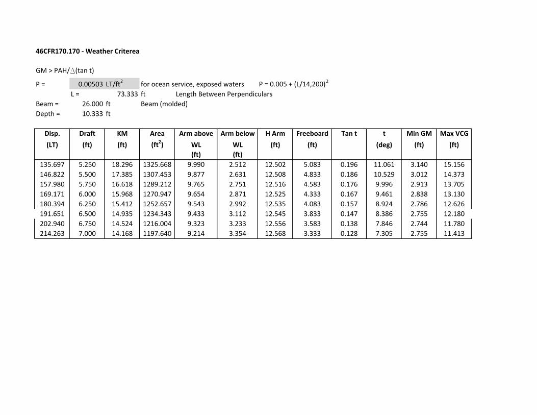
46CFR170.170 - Weather Criterea
GM > PAH/D(tan t)
P = 0.00503 LT/ft2 for ocean service, exposed waters P = 0.005 + (L/14,200)2
L = 73.333 ft Length Between PerpendicularsBeam = 26.000 ft Beam (molded)Depth = 10.333 ft
Disp. Draft KM Area Arm above Arm below H Arm Freeboard Tan t t Min GM Max VCG(LT) (ft) (ft) (ft2) WL WL (ft) (ft) (deg) (ft) (ft)
(ft) (ft)135.697 5.250 18.296 1325.668 9.990 2.512 12.502 5.083 0.196 11.061 3.140 15.156146.822 5.500 17.385 1307.453 9.877 2.631 12.508 4.833 0.186 10.529 3.012 14.373157.980 5.750 16.618 1289.212 9.765 2.751 12.516 4.583 0.176 9.996 2.913 13.705169.171 6.000 15.968 1270.947 9.654 2.871 12.525 4.333 0.167 9.461 2.838 13.130180.394 6.250 15.412 1252.657 9.543 2.992 12.535 4.083 0.157 8.924 2.786 12.626191.651 6.500 14.935 1234.343 9.433 3.112 12.545 3.833 0.147 8.386 2.755 12.180202.940 6.750 14.524 1216.004 9.323 3.233 12.556 3.583 0.138 7.846 2.744 11.780214.263 7.000 14.168 1197.640 9.214 3.354 12.568 3.333 0.128 7.305 2.755 11.413

46 CFR 170.173 (c) Criterion for Vessels of Unusual Proportion and Form
Maximum VCG vs. Displacement
Trim = zero at zero heel (Trim righting arm held at zero)IntactDispl
IntactDraft
Max.VCG
(LT) At 0.000(ft)
(ft)
135.300 5.250 12.320 1128.10% 4.4° 107.80% 0.00% 43.70%146.500 5.500 12.140 978.90% 6.0° 102.00% 0.00% 52.90%157.600 5.750 11.910 866.70% 7.0° 97.30% 0.10% 56.80%168.800 6.000 11.660 784.70% 6.8° 93.40% 0.10% 48.70%180.000 6.250 11.380 727.70% 6.4° 90.00% 0.00% 39.70%191.300 6.500 11.080 691.00% 6.2° 86.70% 0.00% 34.10%202.600 6.750 10.760 671.60% 6.2° 83.70% 0.00% 31.80%213.900 7.000 10.430 666.80% 5.8° 81.00% 0.10% 26.20%
Limit Report
Limit Min/Max>0.49 ft>15.00 deg>16.900 ft-D>5.600 ft-D>11.497 ft-D
(3) Area from 0.00 deg to 40.00 or Flood(2) Absolute Angle at MaxRA(1) GM Upright
(5) Area from 0.00 deg to MaxRA(4) Area from 30.00 deg to 40.00 or Flood
Limit 1 Limit 2 Limit 3 Limit 4 Limit 5
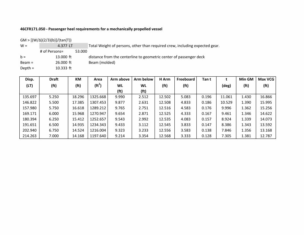
46CFR171.050 - Passenger heel requirements for a mechanically propelled vessel
GM > [(W/∆)(2/3)(b)]/(tan(T))W = 4.377 LT Total Weight of persons, other than required crew, including expected gear.
# of Persons= 53.000b = 13.000 ft distance from the centerline to geometric center of passenger deckBeam = 26.000 ft Beam (molded)Depth = 10.333 ft
Disp. Draft KM Area Arm above Arm below H Arm Freeboard Tan t t Min GM Max VCG(LT) (ft) (ft) (ft2) WL WL (ft) (ft) (deg) (ft) (ft)
(ft) (ft)135.697 5.250 18.296 1325.668 9.990 2.512 12.502 5.083 0.196 11.061 1.430 16.866146.822 5.500 17.385 1307.453 9.877 2.631 12.508 4.833 0.186 10.529 1.390 15.995157.980 5.750 16.618 1289.212 9.765 2.751 12.516 4.583 0.176 9.996 1.362 15.256169.171 6.000 15.968 1270.947 9.654 2.871 12.525 4.333 0.167 9.461 1.346 14.622180.394 6.250 15.412 1252.657 9.543 2.992 12.535 4.083 0.157 8.924 1.339 14.073191.651 6.500 14.935 1234.343 9.433 3.112 12.545 3.833 0.147 8.386 1.343 13.592202.940 6.750 14.524 1216.004 9.323 3.233 12.556 3.583 0.138 7.846 1.356 13.168214.263 7.000 14.168 1197.640 9.214 3.354 12.568 3.333 0.128 7.305 1.381 12.787

46CFR173.095(b) - Towline Pull Criterea
GM > N(PD)2/3sh/(KD(f/B))
N = 2.000 Number of propellersP = 600.000 shp/ea Shaft horsepower per shaftD = 3.417 ft Propeller diameterh = 21.583 ft Vertical distance from shaft centerline to bittK = 38.000 ConstantB = 26.000 ft Beam (molded)Depth = 10.333 ft
Apd = 9.170 ft2Propeller disc area
Ar = 5.514 ft2Projected rudder area at 45 deg in way of propeller disc
s = 0.601
Disp. Draft KM Freeboard Min GM Max VCG(LT) (ft) (ft) (ft) (ft) (ft)
135.697 5.250 18.296 5.083 4.155 14.141146.822 5.500 17.385 4.833 4.039 13.346157.980 5.750 16.618 4.583 3.959 12.659169.171 6.000 15.968 4.333 3.910 12.058180.394 6.250 15.412 4.083 3.891 11.521191.651 6.500 14.935 3.833 3.902 11.033202.940 6.750 14.524 3.583 3.942 10.582214.263 7.000 14.168 3.333 4.013 10.155
Fraction of the propeller circle intercepted by the rudders at 45 deg

Criterea SummaryWeather Unusual Prop & Form Passenger Heel *Towline
46CFR170.170 46CFR 170.173(c) 46CFR171.050 46CFR173.095(b)Disp. Draft KM Max VCG Max VCG Max VCG Max VCG Max VCG(LT) (ft) (ft) (ft) (ft) (ft) (ft) (ft)
135.697 5.250 18.296 15.156 12.320 16.866 14.141 12.320146.822 5.500 17.385 14.373 12.140 15.995 13.346 12.140157.980 5.750 16.618 13.705 11.910 15.256 12.659 11.910169.171 6.000 15.968 13.130 11.660 14.622 12.058 11.660180.394 6.250 15.412 12.626 11.380 14.073 11.521 11.380191.651 6.500 14.935 12.180 11.080 13.592 11.033 11.033202.940 6.750 14.524 11.780 10.760 13.168 10.582 10.582214.263 7.000 14.168 11.413 10.430 12.787 10.155 10.155
*46CFR173.095 requires the vessel to meet either b or c, therefore, b was selected.
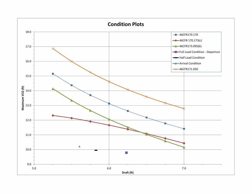
13.0
14.0
15.0
16.0
17.0
18.0
Max
imum
VCG
(ft)Condition Plots
46CFR170.170
46CFR 170.173(c)
46CFR173.095(b)
Full Load Condition - Departure
Half Load Condition
Arrival Condition
46CFR171.050
9.0
10.0
11.0
12.0
5.0 6.0 7.0
Max
imum
VCG
(ft)
Draft (ft)

46CFR173.005(b) - Lifting Criterea
Hmmt = (0.67)(D)(GM)(F/B)
Arrival Fully LoadedBeam (ft) 26.000 26.000GM (ft) 6.327 5.216Depth (ft) 10.333 10.333Draft (ft) 5.618 6.298Freeboard (ft) 4.715 4.035D (LT) 155.380 182.330Hmmt (ft-LT) 119.447 98.887
Crane Max. Reach Min. ReachHook Load (LT) 1.000 1.000Length of Boom (ft) 20.000 20.000Crane Center to CL (ft) 7.000 7.000Max Heeling Moment ofCrane (ft-LT) 27.000 27.000Criteria Condition PASS PASS
The Maximum Heeling Moment of the crane does not exceed the result of the equationfrom 46CFR173.005(b), therefore this requirement does not apply.

Max Free Surface Moments
Tank Status
SALT WATERTank Load Weight LCG TCG VCG Max FSMName (%) (LT) (ft) (ft) (ft) (LT-ft)FWDBALLAST.C 1.025 100.00% 9.09 3.016a 0 5.732 9.9SLOP.C 1.025 100.00% 1.35 53.380a 0 2.983 4.7AFTBALLAST.P 1.025 100.00% 4.41 69.322a 10.658p 7.35 0.7AFTBALLAST.S 1.025 100.00% 4.41 69.322a 10.658s 7.35 0.7
Subtotals: 100.00% 19.26 36.916a 0 6.28 16.1
FRESH WATERTank Load Weight LCG TCG VCG Max FSMName (%) (LT) (ft) (ft) (ft) (LT-ft)FW.P 1 100.00% 2.58 19.814a 3.768p 1.991 1.7FW.S 1 100.00% 2.58 19.814a 3.768s 1.991 1.7GW.S 1 100.00% 1.4 48.342a 1.914s 2.669 0.9
Subtotals: 100.00% 6.55 25.895a 0.408s 2.135 4.3
FUEL OILTank Load Weight LCG TCG VCG Max FSMName (%) (LT) (ft) (ft) (ft) (LT-ft)FO1.P 0.87 100.00% 3.92 33.367a 5.430p 2.113 12.2FO1.S 0.87 100.00% 3.92 33.367a 5.430s 2.113 12.2FO2.P 0.87 100.00% 7.21 42.102a 8.801p 6.233 8.6FO2.S 0.87 100.00% 7.21 42.102a 8.801s 6.233 8.6
Subtotals: 100.00% 22.25 39.027a 0 4.783 41.7
SEWAGETank Load Weight LCG TCG VCG Max FSMName (%) (LT) (ft) (ft) (ft) (LT-ft)BW.P 1.025 100.00% 1.43 48.342a 1.914p 2.669 0.9
Subtotals: 100.00% 1.43 48.342a 1.914p 2.669 0.9
FSM Notes*** Max. FSM is the Maximum Free Surface Moment of any load at thepresent heel and trim. It may not be the current FSM.
Spgr
Spgr
Spgr
Spgr

Full Load Condition - Departure
Load Actual USCGFSM FSM
(LT-ft) (LT-ft)FWDBALLAST.C 0% 0.00 0.00SLOP.C 0% 0.00 0.00AFTBALLAST.P 0% 0.00 0.00AFTBALLAST.S 0% 0.00 0.00FW.P 100% 0.00 1.70FW.S 100% 0.00 1.70GW.S 0% 0.00 0.00FO1.P 95% 12.20 12.20FO1.S 95% 12.20 12.20FO2.P 95% 8.60 8.60FO2.S 95% 8.60 8.60BW.P 0% 0.00 0.00FSM (LT-ft) 41.60 45.00Displacement (LT) 176.90 176.90F/S Correction (ft) 0.235 0.254
GM (Solid) 6.083 ftF/S Correction 0.254 ftGM (Fluid) 5.829 ftKMt 15.616 ftVCG (Corrected) 9.787 ftDraft 6.232 ft
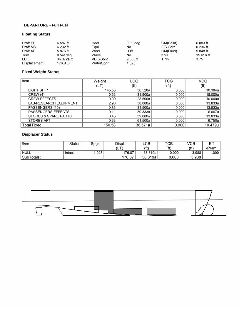
DEPARTURE - Full Fuel
Floating Status
Draft FP 6.587 ft Heel 0.00 deg GM(Solid) 6.083 ftDraft MS 6.232 ft Equil No F/S Corr. 0.236 ftDraft AP 5.876 ft Wind Off GM(Fluid) 5.848 ftTrim 0.54f deg Wave No KMT 15.616 ftLCG 36.372a ft VCG-Solid 9.533 ft TPIn 3.75Displacement 176.9 LT WaterSpgr 1.025
Fixed Weight Status
Item Weight(LT)
LCG(ft)
TCG(ft)
VCG(ft)
LIGHT SHIP 145.53 36.528a 0.000 10.384uCREW (4) 0.33 31.500a 0.000 15.000uCREW EFFECTS 0.09 28.500a 0.000 10.000uLAB-RESEARCH EQUIPMENT 2.90 38.000a 0.000 13.833uPASSENGERS (10) 0.83 31.500a 0.000 13.833uPASSENGERS EFFECTS 0.11 30.333a 0.000 6.667uSTORES & SPARE PARTS 0.45 39.000a 0.000 13.833uSTORES AFT 0.33 61.500a 0.000 6.750u
Total Fixed: 150.58 36.571a 0.000 10.479u
Displacer Status
Item Status Spgr Displ(LT)
LCB(ft)
TCB(ft)
VCB(ft)
Eff/Perm
HULL Intact 1.025 176.87 36.319a 0.000 3.988 1.000SubTotals: 176.87 36.319a 0.000 3.988
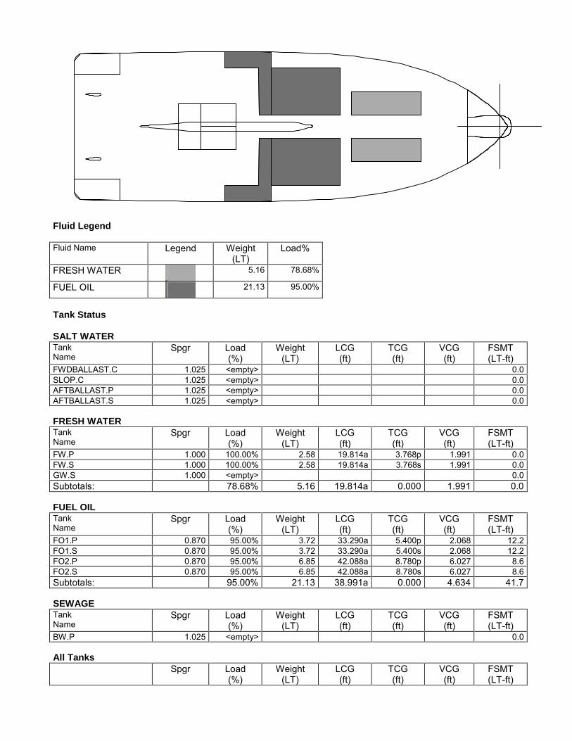
Fluid Legend
Fluid Name Legend Weight(LT)
Load%
FRESH WATER 5.16 78.68%
FUEL OIL 21.13 95.00%
Tank Status
SALT WATERTankName
Spgr Load(%)
Weight(LT)
LCG(ft)
TCG(ft)
VCG(ft)
FSMT(LT-ft)
FWDBALLAST.C 1.025 <empty> 0.0SLOP.C 1.025 <empty> 0.0AFTBALLAST.P 1.025 <empty> 0.0AFTBALLAST.S 1.025 <empty> 0.0
FRESH WATERTankName
Spgr Load(%)
Weight(LT)
LCG(ft)
TCG(ft)
VCG(ft)
FSMT(LT-ft)
FW.P 1.000 100.00% 2.58 19.814a 3.768p 1.991 0.0FW.S 1.000 100.00% 2.58 19.814a 3.768s 1.991 0.0GW.S 1.000 <empty> 0.0Subtotals: 78.68% 5.16 19.814a 0.000 1.991 0.0
FUEL OILTankName
Spgr Load(%)
Weight(LT)
LCG(ft)
TCG(ft)
VCG(ft)
FSMT(LT-ft)
FO1.P 0.870 95.00% 3.72 33.290a 5.400p 2.068 12.2FO1.S 0.870 95.00% 3.72 33.290a 5.400s 2.068 12.2FO2.P 0.870 95.00% 6.85 42.088a 8.780p 6.027 8.6FO2.S 0.870 95.00% 6.85 42.088a 8.780s 6.027 8.6Subtotals: 95.00% 21.13 38.991a 0.000 4.634 41.7
SEWAGETankName
Spgr Load(%)
Weight(LT)
LCG(ft)
TCG(ft)
VCG(ft)
FSMT(LT-ft)
BW.P 1.025 <empty> 0.0
All TanksSpgr Load
(%)Weight
(LT)LCG(ft)
TCG(ft)
VCG(ft)
FSMT(LT-ft)
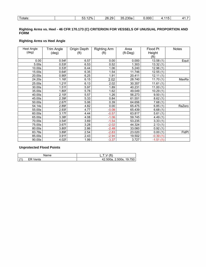
Totals: 53.12% 26.29 35.230a 0.000 4.115 41.7
Righting Arms vs. Heel - 46 CFR 170.173 (C) CRITERION FOR VESSELS OF UNUSUAL PROPORTION ANDFORM
Righting Arms vs Heel Angle
Heel Angle(deg)
Trim Angle(deg)
Origin Depth(ft)
Righting Arm(ft)
Area(ft-Deg)
Flood PtHeight
(ft)
Notes
0.00 0.54f 6.57 0.00 0.000 13.58 (1) Equil5.00s 0.53f 6.53 0.52 1.303 13.32 (1)
10.00s 0.53f 6.44 1.06 5.240 12.96 (1)15.00s 0.64f 6.35 1.54 11.746 12.55 (1)20.00s 0.90f 6.25 1.91 20.411 12.11 (1)24.20s 1.16f 6.15 2.02 28.740 11.70 (1) MaxRa25.00s 1.21f 6.13 2.02 30.357 11.61 (1)30.00s 1.51f 5.97 1.89 40.231 11.00 (1)35.00s 1.80f 5.78 1.62 49.049 10.29 (1)40.00s 2.10f 5.57 1.26 56.273 9.50 (1)45.00s 2.39f 5.33 0.84 61.551 8.62 (1)50.00s 2.67f 5.06 0.39 64.656 7.68 (1)54.14s 2.89f 4.82 0.00 65.475 6.85 (1) RaZero55.00s 2.93f 4.77 -0.08 65.439 6.68 (1)60.00s 3.17f 4.44 -0.57 63.817 5.61 (1)65.00s 3.38f 4.08 -1.06 59.745 4.49 (1)70.00s 3.54f 3.69 -1.54 53.235 3.33 (1)75.00s 3.67f 3.28 -2.02 44.324 2.13 (1)80.00s 3.80f 2.86 -2.48 33.060 0.92 (1)83.78s 3.89f 2.54 -2.83 23.020 0.00 (1) FldPt85.00s 3.91f 2.43 -2.94 19.502 -0.30 (1)90.00s 4.02f 1.99 -3.37 3.727 -1.51 (1)
Unprotected Flood Points
Name L,T,V (ft)(1) ER Vents 42.500a, 2.500s, 19.750

Righting Arms vs. Heel - {BOLD}46 CFR 170.173 (C) CRITERION FOR VESSELS OF UNUSUAL PROPORTION AND FORMHeel angle (Degrees)
Ar
ms
in
ft
0.0s 50.0s
-3.0
-2.0
-1.0
0.0
1.0
2.0Righting ArmR. Area / 100EquilibriumFlood Pt
46 CFR 170.173 (C) CRITERION FOR VESSELS OF UNUSUAL PROPORTION AND FORM
Limit Min/Max Actual Margin Pass(1) GM Upright >0.49 ft 5.85 5.36 Yes(2) Absolute Angle at MaxRA >15.00 deg 24.20 9.20 Yes(3) Area from 0.00 deg to 40.00 or Flood >16.900 ft-D 56.273 39.373 Yes(4) Area from 30.00 deg to 40.00 or Flood >5.600 ft-D 16.042 10.442 Yes(5) Area from 0.00 deg to MaxRA >11.497 ft-D 28.740 17.243 Yes

Half Load Condition
Load Actual USCGFSM FSM
(LT-ft) (LT-ft)FWDBALLAST.C 0% 0.00 0.00SLOP.C 50% 4.70 4.70AFTBALLAST.P 0% 0.00 0.00AFTBALLAST.S 0% 0.00 0.00FW.P 50% 1.60 1.70FW.S 50% 1.60 1.70GW.S 50% 0.90 0.90FO1.P 0% 0.00 0.00FO1.S 0% 0.00 0.00FO2.P 77% 8.10 8.60FO2.S 77% 8.10 8.60BW.P 50% 0.90 0.90FSM (LT-ft) 25.90 27.10Displacement (LT) 161.10 161.10F/S Correction (ft) 0.161 0.168
GM (Solid) 6.657 ftF/S Correction 0.168 ftGM (Fluid) 6.489 ftKMt 16.436 ftVCG (Corrected) 9.947 ftDraft 5.826 ft

HALF TRIP
Floating Status
Draft FP 5.817 ft Heel 0.00 deg GM(Solid) 6.657 ftDraft MS 5.826 ft Equil No F/S Corr. 0.166 ftDraft AP 5.835 ft Wind Off GM(Fluid) 6.492 ftTrim 0.01a deg Wave No KMT 16.436 ftLCG 36.816a ft VCG-Solid 9.779 ft TPIn 3.73Displacement 161.1 LT WaterSpgr 1.025
Fixed Weight Status
Item Weight(LT)
LCG(ft)
TCG(ft)
VCG(ft)
LIGHT SHIP 140.49 36.482a 0.000 10.282uCREW (4) 0.33 31.500a 0.000 15.000uCREW EFFECTS 0.09 28.500a 0.000 10.000uLAB-RESEARCH EQUIPMENT 2.90 38.000a 0.000 13.833uPASSENGERS (10) 0.83 31.500a 0.000 13.833uPASSENGERS EFFECTS 0.11 30.333a 0.000 6.667uSTORES & SPARE PARTS 0.22 39.000a 0.000 13.833uSTORES AFT 0.33 61.500a 0.000 6.750u
Total Fixed: 145.30 36.524a 0.000 10.379u
Displacer Status
Item Status Spgr Displ(LT)
LCB(ft)
TCB(ft)
VCB(ft)
Eff/Perm
HULL Intact 1.025 161.07 36.817a 0.000 3.786 1.000SubTotals: 161.07 36.817a 0.000 3.786

Fluid Legend
Fluid Name Legend Weight(LT)
Load%
SALT WATER .68 3.51%
FRESH WATER 3.28 50.00%
FUEL OIL 11.10 49.90%
SEWAGE .72 50.00%
Tank Status
SALT WATERTankName
Spgr Load(%)
Weight(LT)
LCG(ft)
TCG(ft)
VCG(ft)
FSMT(LT-ft)
FWDBALLAST.C 1.025 <empty> 0.0SLOP.C 1.025 50.00% 0.68 53.261a 0.000 2.595 4.7AFTBALLAST.P 1.025 <empty> 0.0AFTBALLAST.S 1.025 <empty> 0.0Subtotals: 3.51% 0.68 53.261a 0.000 2.595 4.7
FRESH WATERTankName
Spgr Load(%)
Weight(LT)
LCG(ft)
TCG(ft)
VCG(ft)
FSMT(LT-ft)
FW.P 1.000 50.00% 1.29 20.105a 3.553p 1.452 1.6FW.S 1.000 50.00% 1.29 20.105a 3.553s 1.452 1.6GW.S 1.000 50.00% 0.70 48.184a 1.843s 2.123 0.9Subtotals: 50.00% 3.28 26.090a 0.393s 1.595 4.1
FUEL OILTankName
Spgr Load(%)
Weight(LT)
LCG(ft)
TCG(ft)
VCG(ft)
FSMT(LT-ft)
FO1.P 0.870 <empty> 0.0FO1.S 0.870 <empty> 0.0FO2.P 0.870 77.00% 5.55 42.062a 8.715p 5.284 8.5FO2.S 0.870 77.00% 5.55 42.062a 8.715s 5.284 8.5Subtotals: 49.90% 11.10 42.062a 0.000 5.284 17.0
SEWAGETankName
Spgr Load(%)
Weight(LT)
LCG(ft)
TCG(ft)
VCG(ft)
FSMT(LT-ft)
BW.P 1.025 50.00% 0.72 48.184a 1.843p 2.123 0.9

Subtotals: 50.00% 0.72 48.184a 1.843p 2.123 0.9
All TanksSpgr Load
(%)Weight
(LT)LCG(ft)
TCG(ft)
VCG(ft)
FSMT(LT-ft)
Totals: 31.86% 15.77 39.501a 0.002p 4.258 26.7
Righting Arms vs. Heel - 46 CFR 170.173 (C) CRITERION FOR VESSELS OF UNUSUAL PROPORTION ANDFORM
Righting Arms vs Heel Angle
Heel Angle(deg)
Trim Angle(deg)
Origin Depth(ft)
Righting Arm(ft)
Area(ft-Deg)
Flood PtHeight
(ft)
Notes
0.00 0.01a 5.82 0.00 0.000 13.92 (1) Equil5.00s 0.02a 5.79 0.57 1.427 13.65 (1)
10.00s 0.01a 5.71 1.14 5.709 13.30 (1)15.00s 0.15f 5.65 1.63 12.668 12.89 (1)20.00s 0.43f 5.55 1.97 21.711 12.47 (1)24.60s 0.72f 5.40 2.09 31.102 12.05 (1) MaxRa25.00s 0.74f 5.38 2.09 31.936 12.01 (1)30.00s 1.04f 5.16 1.96 42.146 11.46 (1)35.00s 1.32f 4.92 1.67 51.286 10.80 (1)40.00s 1.60f 4.65 1.30 58.749 10.06 (1)45.00s 1.88f 4.35 0.85 64.149 9.23 (1)50.00s 2.15f 4.04 0.37 67.237 8.33 (1)53.73s 2.34f 3.79 0.00 67.940 7.61 (1) RaZero55.00s 2.40f 3.70 -0.13 67.857 7.35 (1)60.00s 2.63f 3.34 -0.64 65.928 6.31 (1)65.00s 2.82f 2.96 -1.16 61.420 5.21 (1)70.00s 3.00f 2.56 -1.67 54.343 4.06 (1)75.00s 3.18f 2.17 -2.18 44.711 2.88 (1)80.00s 3.37f 1.78 -2.68 32.552 1.69 (1)85.00s 3.56f 1.38 -3.17 17.926 0.49 (1)87.04s 3.64f 1.22 -3.36 11.266 0.00 (1) FldPt90.00s 3.73f 0.98 -3.63 0.927 -0.71 (1)
Unprotected Flood Points
Name L,T,V (ft)(1) ER Vents 42.500a, 2.500s, 19.750
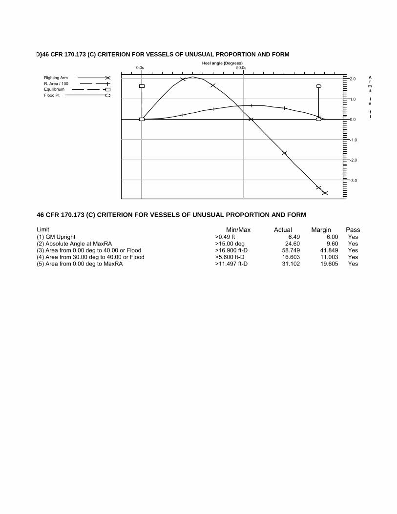
Righting Arms vs. Heel - {BOLD}46 CFR 170.173 (C) CRITERION FOR VESSELS OF UNUSUAL PROPORTION AND FORMHeel angle (Degrees)
Ar
ms
in
ft
0.0s 50.0s
-3.0
-2.0
-1.0
0.0
1.0
2.0Righting ArmR. Area / 100EquilibriumFlood Pt
46 CFR 170.173 (C) CRITERION FOR VESSELS OF UNUSUAL PROPORTION AND FORM
Limit Min/Max Actual Margin Pass(1) GM Upright >0.49 ft 6.49 6.00 Yes(2) Absolute Angle at MaxRA >15.00 deg 24.60 9.60 Yes(3) Area from 0.00 deg to 40.00 or Flood >16.900 ft-D 58.749 41.849 Yes(4) Area from 30.00 deg to 40.00 or Flood >5.600 ft-D 16.603 11.003 Yes(5) Area from 0.00 deg to MaxRA >11.497 ft-D 31.102 19.605 Yes

Arrival Condition
Load Actual USCGFSM FSM
(LT-ft) (LT-ft)FWDBALLAST.C 0% 0.00 0.00SLOP.C 95% 4.70 4.70AFTBALLAST.P 0% 0.00 0.00AFTBALLAST.S 0% 0.00 0.00FW.P 10% 0.50 1.70FW.S 10% 0.50 1.70GW.S 95% 0.90 0.90FO1.P 0% 7.70 0.00FO1.S 0% 7.70 0.00FO2.P 15% 8.00 8.60FO2.S 15% 8.00 8.60BW.P 95% 0.90 0.90FSM (LT-ft) 38.90 27.10Displacement (LT) 152.10 152.10F/S Correction (ft) 0.256 0.178
GM (Solid) 6.969 ftF/S Correction 0.178 ftGM (Fluid) 6.791 ftKMt 17.007 ftVCG (Corrected) 10.216 ftDraft 5.605 ft
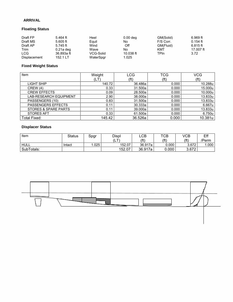
ARRIVAL
Floating Status
Draft FP 5.464 ft Heel 0.00 deg GM(Solid) 6.969 ftDraft MS 5.605 ft Equil No F/S Corr. 0.154 ftDraft AP 5.745 ft Wind Off GM(Fluid) 6.815 ftTrim 0.21a deg Wave No KMT 17.007 ftLCG 36.893a ft VCG-Solid 10.038 ft TPIn 3.72Displacement 152.1 LT WaterSpgr 1.025
Fixed Weight Status
Item Weight(LT)
LCG(ft)
TCG(ft)
VCG(ft)
LIGHT SHIP 140.72 36.486a 0.000 10.288uCREW (4) 0.33 31.500a 0.000 15.000uCREW EFFECTS 0.09 28.500a 0.000 10.000uLAB-RESEARCH EQUIPMENT 2.90 38.000a 0.000 13.833uPASSENGERS (10) 0.83 31.500a 0.000 13.833uPASSENGERS EFFECTS 0.11 30.333a 0.000 6.667uSTORES & SPARE PARTS 0.11 39.000a 0.000 13.833uSTORES AFT 0.33 61.500a 0.000 6.750u
Total Fixed: 145.42 36.526a 0.000 10.381u
Displacer Status
Item Status Spgr Displ(LT)
LCB(ft)
TCB(ft)
VCB(ft)
Eff/Perm
HULL Intact 1.025 152.07 36.917a 0.000 3.672 1.000SubTotals: 152.07 36.917a 0.000 3.672

Fluid Legend
Fluid Name Legend Weight(LT)
Load%
SALT WATER 1.28 6.66%
FRESH WATER 1.84 28.12%
FUEL OIL 2.16 9.72%
SEWAGE 1.36 95.00%
Tank Status
SALT WATERTankName
Spgr Load(%)
Weight(LT)
LCG(ft)
TCG(ft)
VCG(ft)
FSMT(LT-ft)
FWDBALLAST.C 1.025 <empty> 0.0SLOP.C 1.025 95.00% 1.28 53.378a 0.000 2.945 4.7AFTBALLAST.P 1.025 <empty> 0.0AFTBALLAST.S 1.025 <empty> 0.0Subtotals: 6.66% 1.28 53.378a 0.000 2.945 4.7
FRESH WATERTankName
Spgr Load(%)
Weight(LT)
LCG(ft)
TCG(ft)
VCG(ft)
FSMT(LT-ft)
FW.P 1.000 10.00% 0.26 20.596a 2.812p 0.860 0.4FW.S 1.000 10.00% 0.26 20.596a 2.812s 0.860 0.4GW.S 1.000 95.00% 1.33 48.339a 1.911s 2.615 0.9Subtotals: 28.12% 1.84 40.576a 1.376s 2.124 1.7
FUEL OILTankName
Spgr Load(%)
Weight(LT)
LCG(ft)
TCG(ft)
VCG(ft)
FSMT(LT-ft)
FO1.P 0.870 <empty> 0.0FO1.S 0.870 <empty> 0.0FO2.P 0.870 15.00% 1.08 41.474a 7.575p 2.592 8.0FO2.S 0.870 15.00% 1.08 41.474a 7.575s 2.592 8.0Subtotals: 9.72% 2.16 41.474a 0.000 2.592 16.1
SEWAGETankName
Spgr Load(%)
Weight(LT)
LCG(ft)
TCG(ft)
VCG(ft)
FSMT(LT-ft)
BW.P 1.025 95.00% 1.36 48.339a 1.911p 2.615 0.9
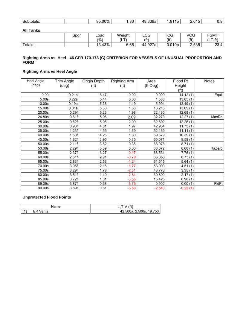
Subtotals: 95.00% 1.36 48.339a 1.911p 2.615 0.9
All TanksSpgr Load
(%)Weight
(LT)LCG(ft)
TCG(ft)
VCG(ft)
FSMT(LT-ft)
Totals: 13.43% 6.65 44.927a 0.010p 2.535 23.4
Righting Arms vs. Heel - 46 CFR 170.173 (C) CRITERION FOR VESSELS OF UNUSUAL PROPORTION ANDFORM
Righting Arms vs Heel Angle
Heel Angle(deg)
Trim Angle(deg)
Origin Depth(ft)
Righting Arm(ft)
Area(ft-Deg)
Flood PtHeight
(ft)
Notes
0.00 0.21a 5.47 0.00 0.000 14.12 (1) Equil5.00s 0.22a 5.44 0.60 1.503 13.85 (1)
10.00s 0.19a 5.38 1.19 5.994 13.49 (1)15.00s 0.01a 5.33 1.68 13.216 13.09 (1)20.00s 0.29f 5.23 1.98 22.430 12.68 (1)24.80s 0.61f 5.06 2.09 32.273 12.27 (1) MaxRa25.00s 0.62f 5.05 2.09 32.692 12.25 (1)30.00s 0.93f 4.81 1.97 42.954 11.73 (1)35.00s 1.23f 4.55 1.69 52.169 11.11 (1)40.00s 1.53f 4.26 1.30 59.679 10.39 (1)45.00s 1.82f 3.95 0.85 65.071 9.59 (1)50.00s 2.11f 3.62 0.35 68.078 8.71 (1)53.38s 2.29f 3.39 0.00 68.672 8.08 (1) RaZero55.00s 2.37f 3.27 -0.17 68.534 7.76 (1)60.00s 2.61f 2.91 -0.70 66.358 6.73 (1)65.00s 2.83f 2.53 -1.24 61.515 5.64 (1)70.00s 3.05f 2.16 -1.77 53.990 4.51 (1)75.00s 3.29f 1.78 -2.31 43.776 3.35 (1)80.00s 3.51f 1.40 -2.84 30.899 2.17 (1)85.00s 3.72f 1.01 -3.35 15.425 0.98 (1)89.09s 3.87f 0.68 -3.75 0.902 0.00 (1) FldPt90.00s 3.89f 0.61 -3.83 -2.540 -0.22 (1)
Unprotected Flood Points
Name L,T,V (ft)(1) ER Vents 42.500a, 2.500s, 19.750

Righting Arms vs. Heel - {BOLD}46 CFR 170.173 (C) CRITERION FOR VESSELS OF UNUSUAL PROPORTION AND FORMHeel angle (Degrees)
Ar
ms
in
ft
0.0s 50.0s
-4.0
-3.0
-2.0
-1.0
0.0
1.0
2.0Righting ArmR. Area / 100EquilibriumFlood Pt
46 CFR 170.173 (C) CRITERION FOR VESSELS OF UNUSUAL PROPORTION AND FORM
Limit Min/Max Actual Margin Pass(1) GM Upright >0.49 ft 6.82 6.33 Yes(2) Absolute Angle at MaxRA >15.00 deg 24.80 9.80 Yes(3) Area from 0.00 deg to 40.00 or Flood >16.900 ft-D 59.679 42.779 Yes(4) Area from 30.00 deg to 40.00 or Flood >5.600 ft-D 16.725 11.125 Yes(5) Area from 0.00 deg to MaxRA >11.497 ft-D 32.273 20.776 Yes

Hydrostatic Properties
Draft is from Baseline.No Trim, No heel, VCG = 0.00
LCFDraft(ft)
Displ(LT)
LCB(ft)
VCB(ft)
LCF(ft)
TPI(LT/inch)
MTI(LT-ft/deg)
KML(ft)
KMT(ft)
5.250 135.326 35.920a 3.452 41.456a 3.70 285.15 120.717 18.3395.500 146.450 36.338a 3.598 41.388a 3.71 288.09 112.698 17.4235.750 157.608 36.693a 3.742 41.323a 3.72 291.03 105.790 16.6516.000 168.799 36.998a 3.883 41.257a 3.74 294.05 99.799 15.9976.250 180.022 37.262a 4.023 41.192a 3.75 297.11 94.552 15.4386.500 191.279 37.491a 4.161 41.126a 3.76 300.24 89.925 14.9596.750 202.568 37.692a 4.299 41.060a 3.77 303.43 85.817 14.5457.000 213.891 37.868a 4.435 40.993a 3.78 306.70 82.150 14.188
Water Specific Gravity = 1.025.
Hydrostatic Properties at Trim = 0.00, Heel = 0.00Long. Location in ft
Draft
@
LCF
42.0a 41.0a 40.0a 39.0a 38.0a 37.0a 36.0a
5.5
6.0
6.5
7.0LCB ftLCF ftVCB ftDispl.LTLT/inch Imm.Mom/Deg TrimKMLKMT
VCB ft x 1 3.0 4.0 5.0Displ.LT x 100 1.5 2.0
LT/inch Imm. x 0.1 37.0 38.0Mom/Deg Trim x 10 29.0 30.0 31.0
KML x 10 8.0 9.0 10.0 11.0 12.0KMT x 1 14.0 15.0 16.0 17.0 18.0 19.0
SPEED/POWER & RANGE/ENDURANCE ANALYSIS
No.: By: Date:0 JRK 25-Nov-15
6129 Churchside Dr.
Lithia, FL 33547
(813) 654-9800
DRAWN BY:JRK
DATE:31-Mar-15
PROJECT: DWG. #: SHEET: REV.: SCALE:
408-Research Vessel 408-844-01 1 OF 3 0 NONE
TITLE:SPEED/ POWER & RANGE ANALYSIS
FIO
SPEED/POWER & RANGE/ENDURANCE ANALYSIS
FOR:
REVISIONS:
Initial Preliminary Issue

SPEED/ POWER &RANGE ANALYSIS
408-844-01 Rev. 25-Nov-15
Principal Characteristics
Length, Molded 77.917 ft.LWL, Waterline Length 73.333 ft.Breadth, Molded 26.000 ft.
General Notes
1. All longitudinal centers are referenced from Station 02. All transverse centers referenced from centerline (Stbd (+), Port (-)).3. All vertical centers referenced from baseline.
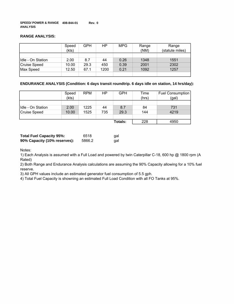
SPEED/ POWER & RANGEANALYSIS
408-844-01 Rev. 0
RANGE ANALYSIS:
Speed GPH HP MPG Range Range(kts) (NM) (statute miles)
Idle - On Station 2.00 8.7 44 0.26 1348 1551Cruise Speed 10.00 29.3 450 0.39 2001 2302Max Speed 12.50 67.1 1200 0.21 1092 1257
ENDURANCE ANALYSIS (Condition: 6 days transit roundtrip. 6 days idle on station, 14 hrs/day):
Speed RPM HP GPH Time Fuel Consumption(kts) (hrs) (gal)
Idle - On Station 2.00 1225 44 8.7 84 731Cruise Speed 10.00 1525 735 29.3 144 4219
Totals: 228 4950
Total Fuel Capacity 95%: 6518 gal90% Capacity (10% reserves): 5866.2 gal
Notes:
3) All GPH values include an estimated generator fuel consumption of 5.5 gph.4) Total Fuel Capacity is showning an estimated Full Load Condition with all FO Tanks at 95%.
1) Each Analysis is assumed with a Full Load and powered by twin Caterpillar C-18, 600 hp @ 1800 rpm (ARated)2) Both Range and Endurance Analysis calculations are assuming the 90% Capacity allowing for a 10% fuelreserve.


