Bimmer Retrofit Installation Instruction
Retrofits and remote coding
Rear-view Camera Installation Instruction (with Front Camera support)
Rev 2.02
BEFORE YOU START
READ THE COMPLETE INSTRUCTIONS CAREFULLY BEFORE BEGINNING THE INSTALLATION
IF YOU HAVE ANY QUESTIONS ABOUT THE USE OF THIS DEVICE, CONTACT YOUR BIMMER RETROFIT REPRESENTATIVE BEFORE USE
Installation of Rear-view Camera Retrofit should be performed by an installer with appropriate
knowledge and experience. We strongly recommend using services of professional installers,
experienced with BMWs, for this installation.
Battery should be disconnected prior to the installation for safety reasons. Reconnection of the battery
should be done only after all electrical connections are in place.
For self-coding feature to work, your vehicle’s software must be recent (or at least from 2011).
For normal operation of PDC (if available), vehicle’s software must be recent (or at least from 2011).
This manual covers installation of the Rear View cameras of two types: Rear View Camera with Static
Guidelines and Rear View Camera with Dynamic Guidelines (with front camera support). Both camera
types requires very similar installation technic with just a few minor differences. Dynamic guidelines
camera module also supports front camera connection.

Bimmer Retrofit Installation Instruction
Retrofits and remote coding
Contents DEVICE OVERVIEW ....................................................................................................................................... 3
Discontinued models ................................................................................................................................ 3
Current models ......................................................................................................................................... 4
INSTALLATION OF REAR-VIEW CAMERA CONTROL MODULE ..................................................................... 5
REPLACING THE TRUNK HANDLE ............................................................................................................... 10
PASSING THE WIRES FROM HEAD UNIT TO THE TRUNK HANDLE ............................................................ 11
FRONT CAMERA INSTALLATION ................................................................................................................. 14
IS CODING REQUIRED IN YOUR CASE? ....................................................................................................... 15
CAMERA MODULE CONFIGURATION MODES SELECTION .................................................................... 16
REAR VIEW CAMERA SELF CODING MODE ............................................................................................ 20
FIRMWARE UPDATE MODE FOR CAMERA MODULE ............................................................................. 25
MANUAL FIRMWARE UPDATE MODE FOR THE CAMERA MODULE ......................................................... 27
Bimmer Retrofit Installation Instruction
Retrofits and remote coding
DEVICE OVERVIEW
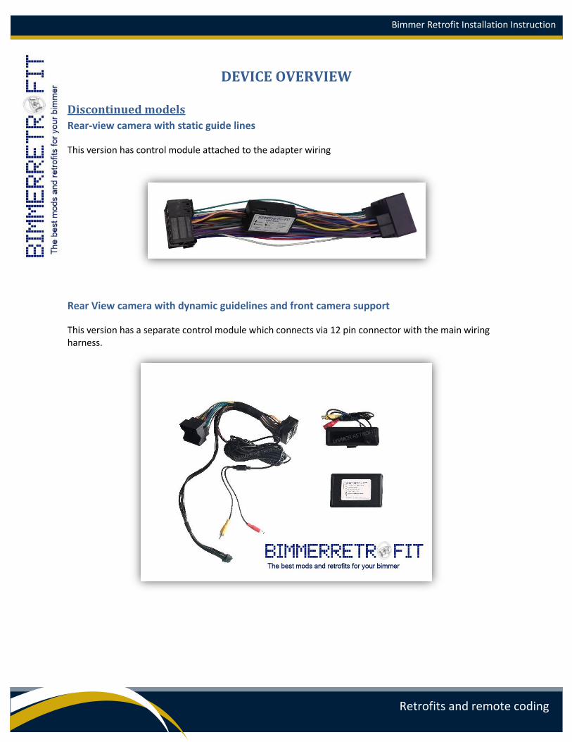
Discontinued models
Rear-view camera with static guide lines
This version has control module attached to the adapter wiring
Rear View camera with dynamic guidelines and front camera support
This version has a separate control module which connects via 12 pin connector with the main wiring harness.
Bimmer Retrofit Installation Instruction
Retrofits and remote coding
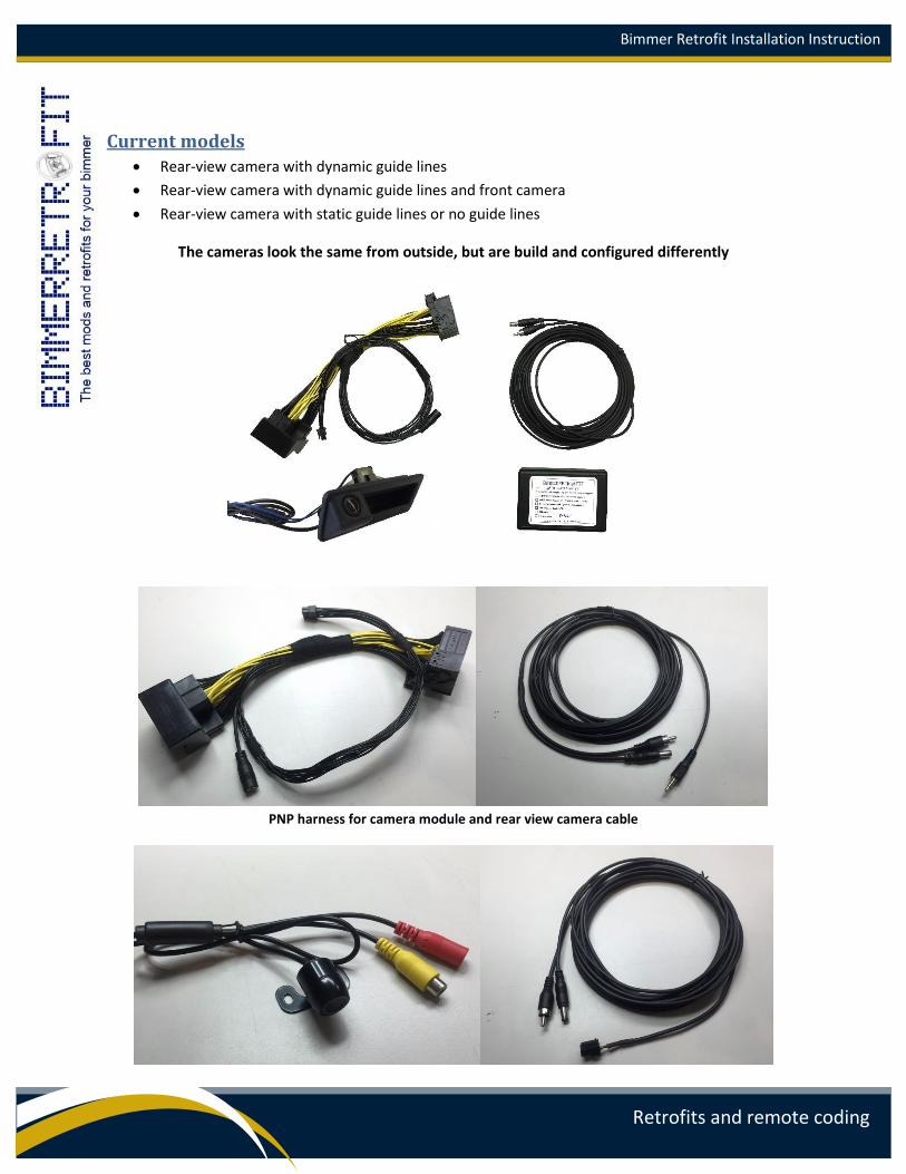
Current models
Rear-view camera with dynamic guide lines
Rear-view camera with dynamic guide lines and front camera
Rear-view camera with static guide lines or no guide lines
The cameras look the same from outside, but are build and configured differently
PNP harness for camera module and rear view camera cable
Bimmer Retrofit Installation Instruction
Retrofits and remote coding
Front camera and front camera cable
INSTALLATION OF REAR-VIEW CAMERA CONTROL MODULE
STEP 1
Remove CIC/NBT head unit (‘head unit’) from its position (but do not disconnect any of the wiring just
yet). This will require you to remove some plastic trim on your dashboard and unscrew appropriate
screws.
Depending on the model of your BMW, you may need to switch transmission to ‘Drive” position, before
removing the head unit (to give more space to maneuver).
We also recommend that you place some protective blanket on the center console trim, to avoid
possible scratches and dents.
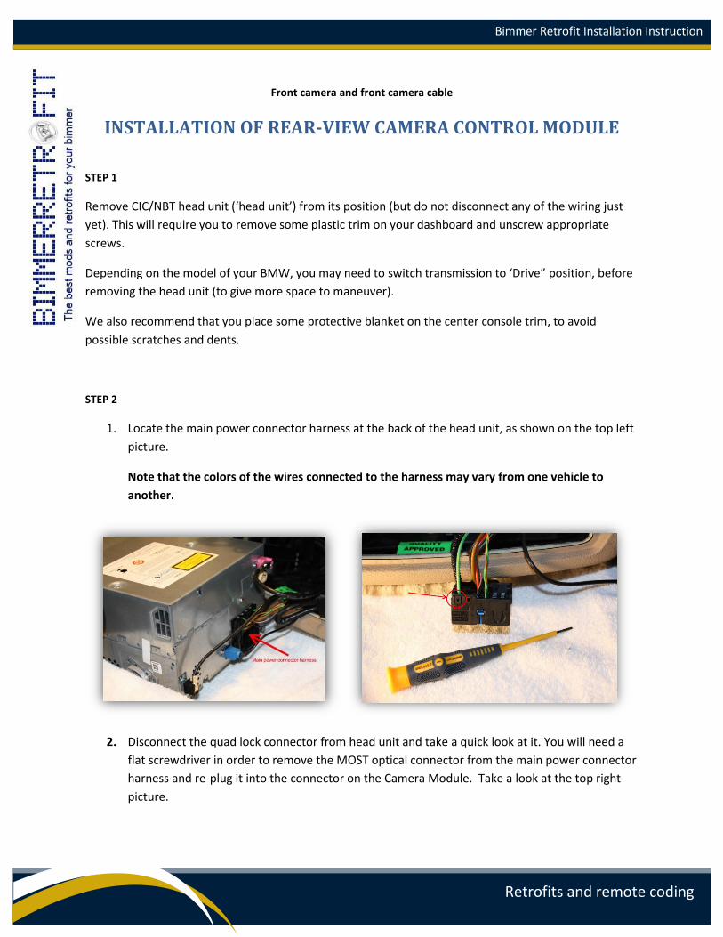
STEP 2
1. Locate the main power connector harness at the back of the head unit, as shown on the top left
picture.
Note that the colors of the wires connected to the harness may vary from one vehicle to
another.
2. Disconnect the quad lock connector from head unit and take a quick look at it. You will need a
flat screwdriver in order to remove the MOST optical connector from the main power connector
harness and re-plug it into the connector on the Camera Module. Take a look at the top right
picture.

Bimmer Retrofit Installation Instruction
Retrofits and remote coding
WARNING ! It is important to reconnect this MOST optical cable in
order to avoid loss of sound and other multimedia features.
If your vehicle does not have this MOST optical connector (vehicle with no MOST and with no top
HiFi Logic 7 or other high end amplifiers) then you do not need to reconnect this cable.
3. Gently pull the plastic lock on the connector using a screwdriver and pull up the two optical
cables.
4. Now re-plug this optical connector into the same position on the Camera Module’s connector.
5. Now connect the Main power connector harness into the opposite end of the Camera Module’s
connector.
Bimmer Retrofit Installation Instruction
Retrofits and remote coding
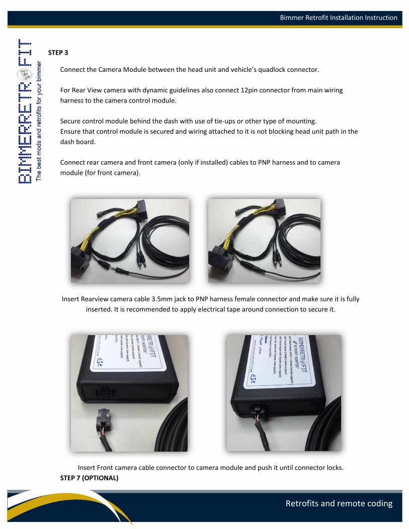
STEP 3
Connect the Camera Module between the head unit and vehicle’s quadlock connector.
For Rear View camera with dynamic guidelines also connect 12pin connector from main wiring
harness to the camera control module.
Secure control module behind the dash with use of tie-ups or other type of mounting.
Ensure that control module is secured and wiring attached to it is not blocking head unit path in the
dash board.
Connect rear camera and front camera (only if installed) cables to PNP harness and to camera
module (for front camera).
Insert Rearview camera cable 3.5mm jack to PNP harness female connector and make sure it is fully
inserted. It is recommended to apply electrical tape around connection to secure it.
Insert Front camera cable connector to camera module and push it until connector locks.
STEP 7 (OPTIONAL)

Bimmer Retrofit Installation Instruction
Retrofits and remote coding
IF YOU WANT TO SIMPLIFY FUTURE FIRMWARE UPDATE OF THE CAMERA MODULE
1. Connect Micro USB cable to the Camera Module (only for Beta test or if you prefer to have easy
ability to update internal module’s firmware in the future).
2. Another end of the USB cable should be passed under the dashboard and left floating outside for
future use with laptop for firmware updates.
Refer to the appropriate section of the instructions for more information on connecting USB cable
to the Camera Module.
STEP 4 (RE-INSTALLING THE HEAD UNIT)
Re-install your head unit inside the dash board.
Normally at the back of the head unit tunnel in the dash board on the right or left side,
there will be some sort of opening. You may use that opening to install the Camera
Module. This will let you install head unit until completely, to the end of the tunnel.
Warning! Avoid installing camera module in direct contact with hot surfaces (head unit
surface, vehicle heater surface, etc). Excessive temperature may damage camera module.
Bimmer Retrofit Installation Instruction
Retrofits and remote coding
TEST OF CAMERA BEFORE INSTALLATION
IMPORTANT INFORMATION BEFORE YOU PROCEED TO THE NEXT STEP
It is not mandatory but HIGHLY RECOMMENDED to test your camera and make sure that it works in
prior to passing all wiring in to the back and installing camera in its original place.
Assume that at this point you have your Camera module installed and connected to the head unit.
Camera wire from module is not yet passed across the vehicle in to the back.
Now it is a good moment to make a camera test.
1. Connect your camera to main adapter’s camera cable and place it somewhere near you.
IMPORTANT: Make sure that the camera plug is inserted into the connector on the cable until the
end.
It may be a little bit hard to push it until the end but the plug of the camera should be fully inserted,
otherwise camera will not work. It is strongly suggested to isolate each connector of the camera
(power connector, video connector, handle connector) for better effect.
2. Temporary skip next steps and go directly to STEP11. Connect back battery terminal temporary
for testing of the camera. At this time camera must be connected to vehicle.
3. Turn ignition ON-OFF-ON at least 2-3 times to allow camera module to detect your vehicle.
4. Proceed with head unit self-coding via camera adapter (see REAR VIEW CAMERA SELF
CODING MODE).
5. While engine is running or ignition is on turn Reverse gear and make sure that you have actual
picture from the camera on the display of the head unit. In case if front camera is also installed
move iDrive controller’s knob forward and hold it for few seconds until video feed from front
camera appears. If all looks okay means you have properly connected camera adapter to your
head unit and your camera(s) work.
6. Disconnect battery terminal again and continue with the next steps of camera installation.
This checkup above is not mandatory but HIGHLY RECOMMENDED.
The idea of this checkup is to ensure that the video feed from the camera(s) is OKAY.
Bimmer Retrofit Installation Instruction
Retrofits and remote coding
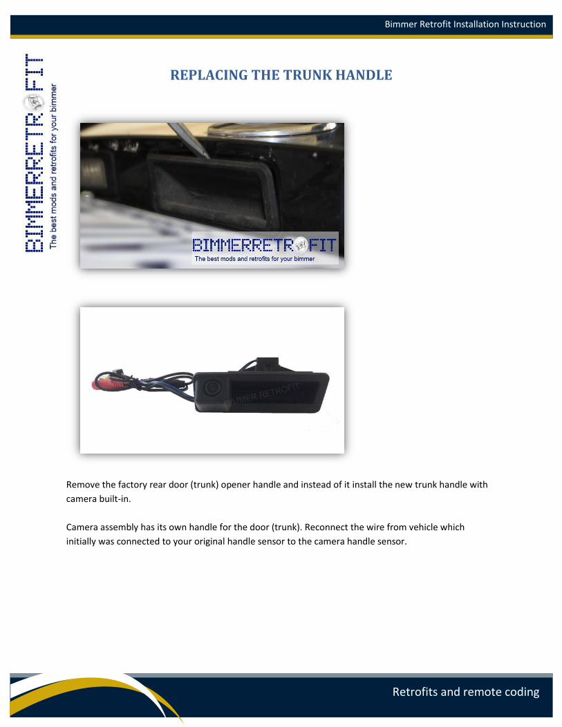
REPLACING THE TRUNK HANDLE
Remove the factory rear door (trunk) opener handle and instead of it install the new trunk handle with
camera built-in.
Camera assembly has its own handle for the door (trunk). Reconnect the wire from vehicle which
initially was connected to your original handle sensor to the camera handle sensor.
Bimmer Retrofit Installation Instruction
Retrofits and remote coding
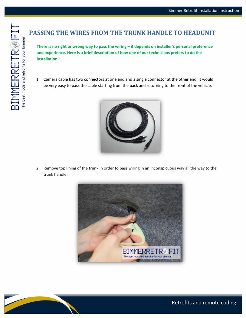
PASSING THE WIRES FROM THE TRUNK HANDLE TO HEADUNIT
There is no right or wrong way to pass the wiring – it depends on installer’s personal preference
and experience. Here is a brief description of how one of our technicians prefers to do the
installation.
1. Camera cable has two connectors at one end and a single connector at the other end. It would
be very easy to pass the cable starting from the back and returning to the front of the vehicle.
2. Remove top lining of the trunk in order to pass wiring in an inconspicuous way all the way to the
trunk handle.
Bimmer Retrofit Installation Instruction
Retrofits and remote coding
3. Once you get the trunk handle, just connect the cable to the connectors on the camera, built into
the trunk handle.
IMPORTANT: Connect both yellow and red connectors to the camera cable. It is strongly
recommended to secure each connector with electrical tape and with tie-ups to the trunk body to
protect it from vibration and humidity.
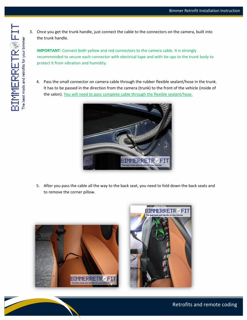
4. Pass the small connector on camera cable through the rubber flexible sealant/hose in the trunk.
It has to be passed in the direction from the camera (trunk) to the front of the vehicle (inside of
the salon). You will need to pass complete cable through the flexible sealant/hose.
5. After you pass the cable all the way to the back seat, you need to fold down the back seats and
to remove the corner pillow.
Bimmer Retrofit Installation Instruction
Retrofits and remote coding
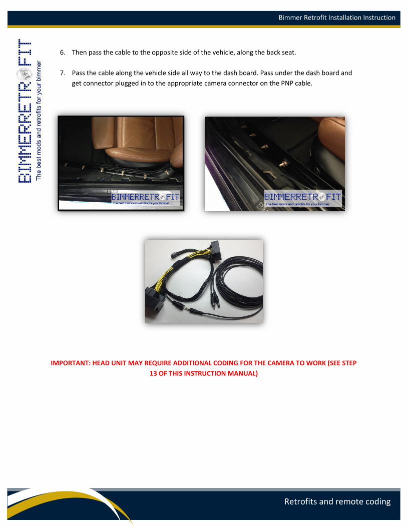
6. Then pass the cable to the opposite side of the vehicle, along the back seat.
7. Pass the cable along the vehicle side all way to the dash board. Pass under the dash board and
get connector plugged in to the appropriate camera connector on the PNP cable.
IMPORTANT: HEAD UNIT MAY REQUIRE ADDITIONAL CODING FOR THE CAMERA TO WORK (SEE STEP
13 OF THIS INSTRUCTION MANUAL)

Bimmer Retrofit Installation Instruction
Retrofits and remote coding
FRONT CAMERA INSTALLATION Front camera can be installed on the front bumper. Use any opening in the bumper with sufficient
space to install camera. It is not recommended to install camera very low as it may be easily
damaged. Secure camera mount with two screws to plastic of the bumper.
Pass front camera cable through front vehicle’s firewall and reach with cable to camera connectors.
Connect both yellow and red connectors. Apply electrical tape around connectors to secure them
and avoid water to be in contact with metal parts of the connectors.
Use tie-ups to secure the wiring to vehicle’s bumper grill. Any other way of securing wires can also
be used.
Warning: Avoid routing camera cable under the hood in any areas where direct heat with
excessive temperature is produced as it may damage the cable.
Make sure that camera cable under the hood is routed via designated for wiring areas along with
other cables (lights, sensors, etc cables).
After camera is installed it is required to adjust its horizon. Simply unscrew the camera a little and
adjust it by viewing the live feed from the camera (this task may require two people) and rotating
camera in its mount across the axel. Once horizon is adjusted screw and tied up the camera back in
mount.
Bimmer Retrofit Installation Instruction
Retrofits and remote coding
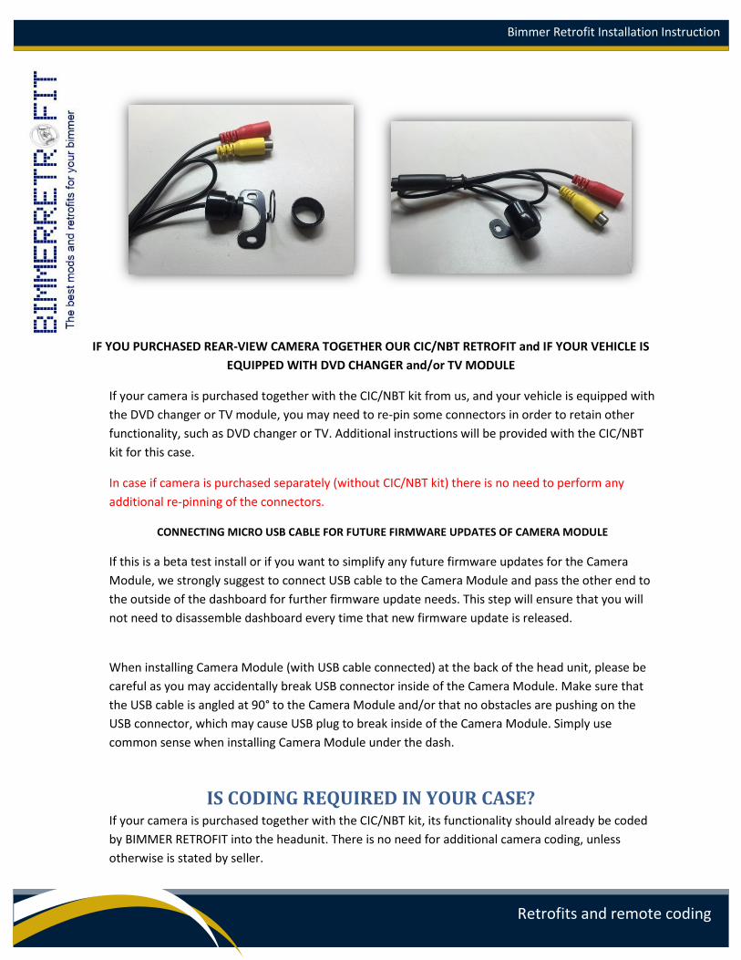
IF YOU PURCHASED REAR-VIEW CAMERA TOGETHER OUR CIC/NBT RETROFIT and IF YOUR VEHICLE IS
EQUIPPED WITH DVD CHANGER and/or TV MODULE
If your camera is purchased together with the CIC/NBT kit from us, and your vehicle is equipped with
the DVD changer or TV module, you may need to re-pin some connectors in order to retain other
functionality, such as DVD changer or TV. Additional instructions will be provided with the CIC/NBT
kit for this case.
In case if camera is purchased separately (without CIC/NBT kit) there is no need to perform any
additional re-pinning of the connectors.
CONNECTING MICRO USB CABLE FOR FUTURE FIRMWARE UPDATES OF CAMERA MODULE
If this is a beta test install or if you want to simplify any future firmware updates for the Camera
Module, we strongly suggest to connect USB cable to the Camera Module and pass the other end to
the outside of the dashboard for further firmware update needs. This step will ensure that you will
not need to disassemble dashboard every time that new firmware update is released.
When installing Camera Module (with USB cable connected) at the back of the head unit, please be
careful as you may accidentally break USB connector inside of the Camera Module. Make sure that
the USB cable is angled at 90° to the Camera Module and/or that no obstacles are pushing on the
USB connector, which may cause USB plug to break inside of the Camera Module. Simply use
common sense when installing Camera Module under the dash.
IS CODING REQUIRED IN YOUR CASE? If your camera is purchased together with the CIC/NBT kit, its functionality should already be coded
by BIMMER RETROFIT into the headunit. There is no need for additional camera coding, unless
otherwise is stated by seller.
Bimmer Retrofit Installation Instruction
Retrofits and remote coding
In case if your camera is purchased separately, additional coding is required in order to activate
rear-view camera. This coding is done for your head unit which must be configured to accept
camera.
Your rear-view camera is self-coding. This means the camera module has a built-in coding feature,
and the camera can code head unit since it is directly connected with it.
WARNING: Self coding is available ONLY for E series head units.
For F series CIC head units remote coding is required.
For F series NBT head units software coding solution via USB will be provided.
IMPORTANT: See next sections for instructions on how to use the self-coding feature.
CAMERA MODULE CONFIGURATION MODES SELECTION
1. Your Camera Module has a built-in logic which allows you to perform configuration using the
iDrive controller of your vehicle. Clock in the head unit is used for results output and for
interaction. This configuration mode is called iClick Mode.
2. In order to switch your Camera Module to the configuration mode, you have to make sure that
your head unit is turned on and you can see Main Menu on the display.
3. There are two methods of configuring your camera control module – via iClick technology or via
separate free PC utility by connecting your PC via USB cable to camera module. Below we provide
instructions for camera configuring via iClick technology. Description of camera configuring via PC
utility described at the end of this manual.
4. Configuration can be performed using iDrive controller rotation clicks. To select any desired
function, you need to enter the 3 digit code value, associated with the desired function. A list of
available functions and associated 3 digit codes are provided in the next section.
Below it is explained how you can enter this 3 digit value using the iDrive controller:
a. For example we need to select option called: Video in Motion (VIM) activation or
deactivation. Code 3-1-2 is assigned to this function.
Bimmer Retrofit Installation Instruction
Retrofits and remote coding
b. Press ‘Menu’ button and hold it for approximately 7 seconds. While holding the button
down keep an eye on the clock in the head unit. As soon as you see time 0:00, that
means you have entered the configuration mode. (If your system set to AM/PM time
you will see 12:00 instead of 0:00)
c. Now rotate your iDrive controller clockwise (to the right) very slowly – one click by one
– and watch your clock on head unit display. You will see that as you turn the iDrive
controller to the right, hours increase from 0 to 5 with each click (0:00 1:00 ….
5:00). You need to make the ‘hour’ value equal to 3 (since our VIM option code is 3-1-
2 and first number is 3). The clock on the display should display 3:00.
d. Now rotate your iDrive controller counter-clockwise (to the left) very slowly – just for 1
click. You will see that the second value on the clock (minutes) will become 1 (3:00
3:10) Now you have selected second number from VIM option code which is 3-1-2.
e. Now rotate your iDrive controller clockwise (to the right) very slowly – one click by one
– and watch your clock on head unit display. Once you turned the iDrive controller to
the right for 2 clicks, you will see that you the third value on the clock (minutes) will
increase from 0 value to 2 (3:103:113:12). Once you see that the value on the clock
of head unit matches the VIM option code 3-1-2 (on display it should be 3:12) you are
done with selection.
f. Now you have to push the iDrive controller know down and hold it for a little bit more
than a second, until you see the value 11:00 or 11:01 or --:-- (for camera self coding
mode values are 03:03 or 10:10. Pls see in appropriate section of manual)
g. These values may show up only for a second or two and disappear after. Value 11:00
means that the option which you just choose is Deactivated (00 in minutes value means
Turned OFF). Value 11:01 means that the option which you just selected is Activated (01
in minutes value means Turned ON). This is true when you select the options which can
be left ON or OFF for long period of time. Video In Motion option can be kept ON or OFF
for any amount of time. However if the option which you choose is a service option (for
example Firmware Update) you may see the message like: --:-- instead of 11:00 or 11:01
h. In case if during selection of the option code, you jumped over the desired value you
may easily reset to 0:00. Simply rotate iDrive controller to the left until you see 0:00 in
clock of the NBT display. (If your system set to AM/PM time you will see 12:00 instead
of 0:00)
i. In order to return back to the normal mode without selecting any option, push down
iDrive knob while selecting code 0:00 which means: No option selected.
Bimmer Retrofit Installation Instruction
Retrofits and remote coding
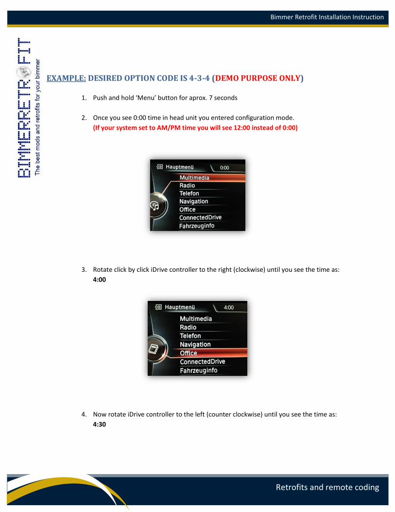
EXAMPLE: DESIRED OPTION CODE IS 4-3-4 (DEMO PURPOSE ONLY)
1. Push and hold ‘Menu’ button for aprox. 7 seconds
2. Once you see 0:00 time in head unit you entered configuration mode.
(If your system set to AM/PM time you will see 12:00 instead of 0:00)
3. Rotate click by click iDrive controller to the right (clockwise) until you see the time as:
4:00
4. Now rotate iDrive controller to the left (counter clockwise) until you see the time as:
4:30
Bimmer Retrofit Installation Instruction
Retrofits and remote coding
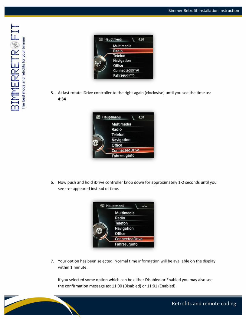
5. At last rotate iDrive controller to the right again (clockwise) until you see the time as:
4:34
6. Now push and hold iDrive controller knob down for approximately 1-2 seconds until you
see --:-- appeared instead of time.
7. Your option has been selected. Normal time information will be available on the display
within 1 minute.
If you selected some option which can be either Disabled or Enabled you may also see
the confirmation message as: 11:00 (Disabled) or 11:01 (Enabled).
Bimmer Retrofit Installation Instruction
Retrofits and remote coding
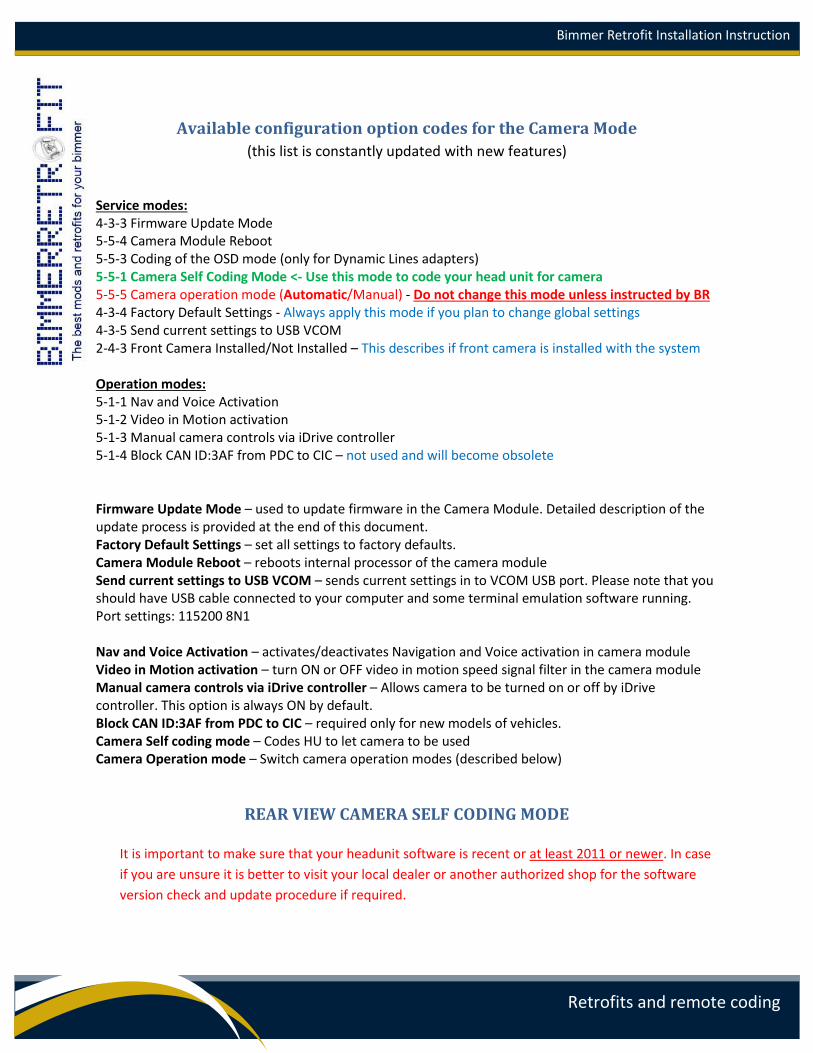
Available configuration option codes for the Camera Mode
(this list is constantly updated with new features)
Service modes: 4-3-3 Firmware Update Mode 5-5-4 Camera Module Reboot 5-5-3 Coding of the OSD mode (only for Dynamic Lines adapters) 5-5-1 Camera Self Coding Mode <- Use this mode to code your head unit for camera 5-5-5 Camera operation mode (Automatic/Manual) - Do not change this mode unless instructed by BR 4-3-4 Factory Default Settings - Always apply this mode if you plan to change global settings 4-3-5 Send current settings to USB VCOM 2-4-3 Front Camera Installed/Not Installed – This describes if front camera is installed with the system Operation modes: 5-1-1 Nav and Voice Activation 5-1-2 Video in Motion activation 5-1-3 Manual camera controls via iDrive controller 5-1-4 Block CAN ID:3AF from PDC to CIC – not used and will become obsolete
Firmware Update Mode – used to update firmware in the Camera Module. Detailed description of the update process is provided at the end of this document. Factory Default Settings – set all settings to factory defaults. Camera Module Reboot – reboots internal processor of the camera module Send current settings to USB VCOM – sends current settings in to VCOM USB port. Please note that you should have USB cable connected to your computer and some terminal emulation software running. Port settings: 115200 8N1 Nav and Voice Activation – activates/deactivates Navigation and Voice activation in camera module Video in Motion activation – turn ON or OFF video in motion speed signal filter in the camera module Manual camera controls via iDrive controller – Allows camera to be turned on or off by iDrive controller. This option is always ON by default. Block CAN ID:3AF from PDC to CIC – required only for new models of vehicles. Camera Self coding mode – Codes HU to let camera to be used Camera Operation mode – Switch camera operation modes (described below)
REAR VIEW CAMERA SELF CODING MODE
It is important to make sure that your headunit software is recent or at least 2011 or newer. In case
if you are unsure it is better to visit your local dealer or another authorized shop for the software
version check and update procedure if required.
Bimmer Retrofit Installation Instruction
Retrofits and remote coding
1. Following the instructions above select Camera Self Coding Mode (5-5-1) from the available
iClick options. After pushing down the iDrive knob you must see 03:03 in time display of your
head unit. This means that coding was correctly started.
In case if you see 10:10 in time display of your head unit means that coding failed and:
- your camera module is in Automatic mode and you have not turned ON-OFF-ON ignition at
least two-three times after module was installed and connected
OR
- your camera module is in Manual mode and you have not selected proper Vehicle Specific
Mode.
Fix the issue and repeat complete step again!
2. As soon as coding started you will notice that the Telephone menu on the CIC becomes grey for
some time and after that iDrive controller become unresponsive for the entire duration of the
coding. Also some warning messages may show up on the display depending on the vehicle’s
configuration. This is normal behavior during the coding process. Do not interrupt or switch off
the headunit.
3. After approximatelly 10-25 seconds, your headunit will reboot. Once you see that display
reboots, this means that the coding is completed. You may now test your camera or continue
installation if not yet finished with the the installation of the hardware.
There is no need to repeat self coding again if succeeded, unless the head
unit has been recoded or reprogrammed for any reason using dealer’s
software.
It is important to keep ignition on and to not disconnect head unit or Camera Module during
coding procedure.
Reboot of the head unit is a confirmation of a successful coding. If the head unit does not
reboot, it means that the coding has not finished successfully for some reason. Indication of the
time as described above will also indicate the status of the coding.
In some cases you may push Volume knob down for at least 30 seconds (MUTE button) and after
that your head unit will reboot.
In case if camera not work after coding you will need remote coding over the internet to be done by
one of our specialists. For that you will need to have a USB K+DCAN cable. This is very unlikely case
if your head unit complies with minimum required software version and installation is properly
done.
Bimmer Retrofit Installation Instruction
Retrofits and remote coding
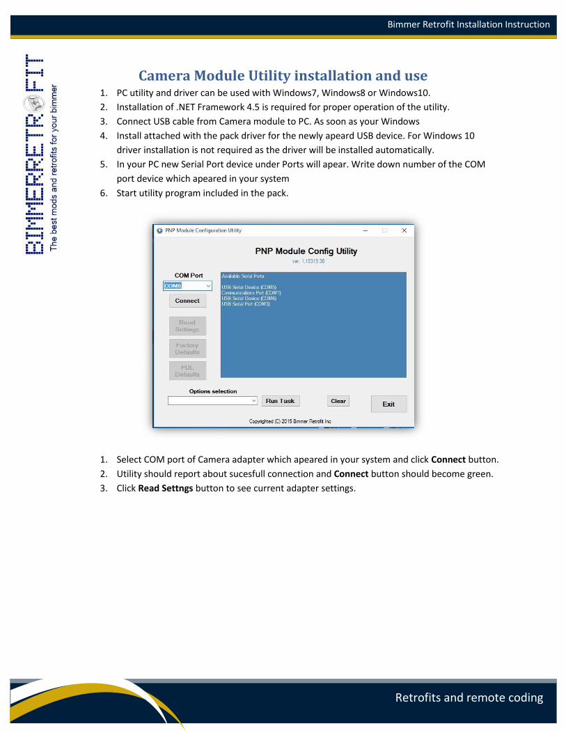
Camera Module Utility installation and use 1. PC utility and driver can be used with Windows7, Windows8 or Windows10.
2. Installation of .NET Framework 4.5 is required for proper operation of the utility.
3. Connect USB cable from Camera module to PC. As soon as your Windows
4. Install attached with the pack driver for the newly apeard USB device. For Windows 10
driver installation is not required as the driver will be installed automatically.
5. In your PC new Serial Port device under Ports will apear. Write down number of the COM
port device which apeared in your system
6. Start utility program included in the pack.
1. Select COM port of Camera adapter which apeared in your system and click Connect button.
2. Utility should report about sucesfull connection and Connect button should become green.
3. Click Read Settngs button to see current adapter settings.
Bimmer Retrofit Installation Instruction
Retrofits and remote coding
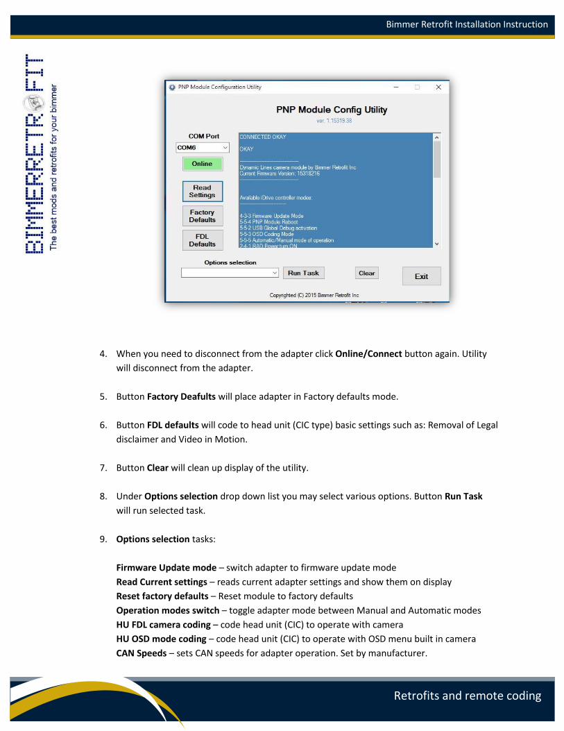
4. When you need to disconnect from the adapter click Online/Connect button again. Utility
will disconnect from the adapter.
5. Button Factory Deafults will place adapter in Factory defaults mode.
6. Button FDL defaults will code to head unit (CIC type) basic settings such as: Removal of Legal
disclaimer and Video in Motion.
7. Button Clear will clean up display of the utility.
8. Under Options selection drop down list you may select various options. Button Run Task
will run selected task.
9. Options selection tasks:
Firmware Update mode – switch adapter to firmware update mode
Read Current settings – reads current adapter settings and show them on display
Reset factory defaults – Reset module to factory defaults
Operation modes switch – toggle adapter mode between Manual and Automatic modes
HU FDL camera coding – code head unit (CIC) to operate with camera
HU OSD mode coding – code head unit (CIC) to operate with OSD menu built in camera
CAN Speeds – sets CAN speeds for adapter operation. Set by manufacturer.
Bimmer Retrofit Installation Instruction
Retrofits and remote coding
BR Rear Camera mode – Describes if rear camera is conencted (must be always ON)
BR Front Camera mode – Describes if front camera is connected.
Other modes also can be switched (ON/OFF) using this drop down menu.
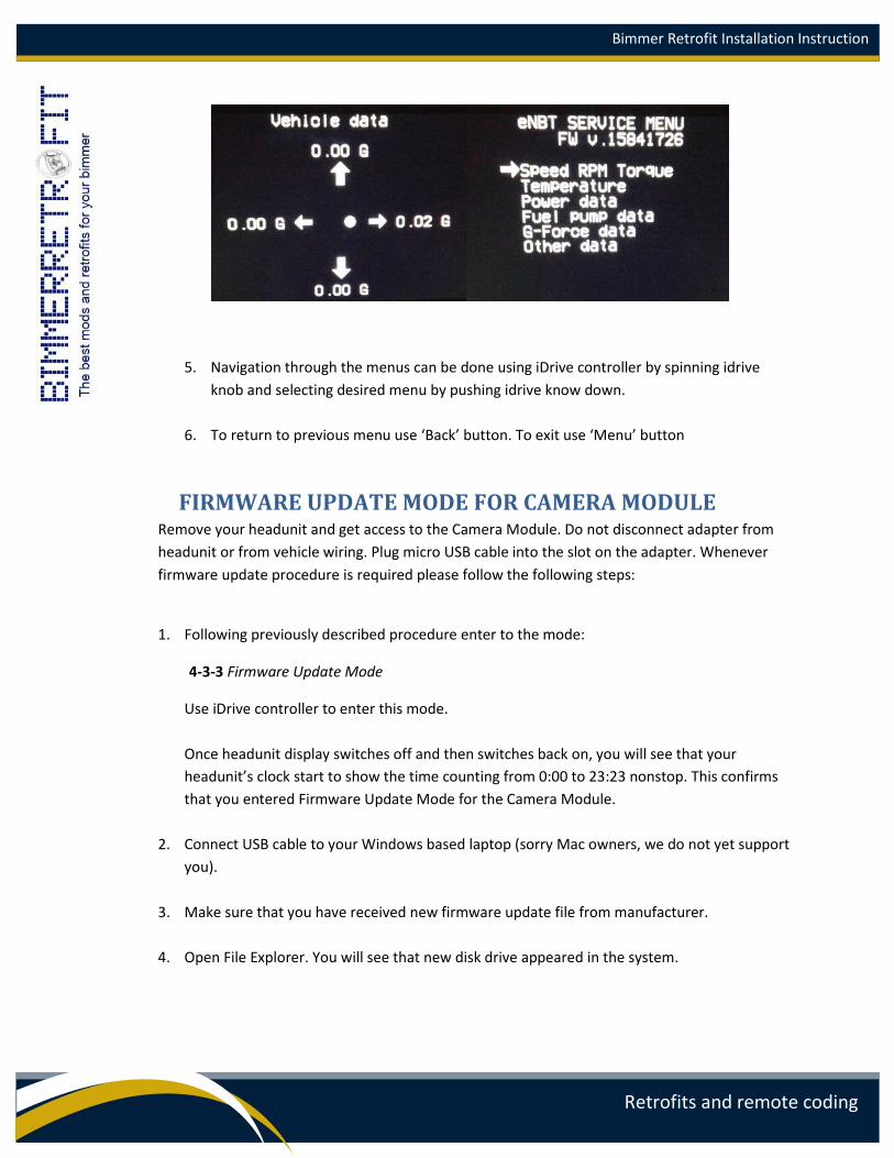
BUILT IN OSD MENU OPERATION
1. Camera module with dynamic lines comes with built in OSD menu. Depends on the
version of the camera and firmware type additional information can be shown on head
unit display. Vehicle live data or external sensor values can be shown on display of head
unit.
2. For OSD menu activation installer initially has to perform Coding of the OSD mode task
via iClick or via PC utility (HU OSD mode coding). This has to be done once during
adapter and head unit configuration.
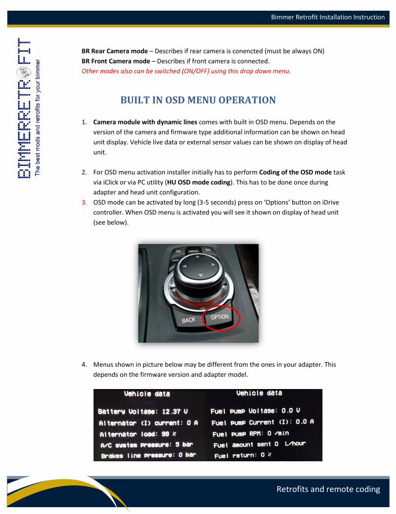
3. OSD mode can be activated by long (3-5 seconds) press on ‘Options’ button on iDrive
controller. When OSD menu is activated you will see it shown on display of head unit
(see below).
4. Menus shown in picture below may be different from the ones in your adapter. This
depends on the firmware version and adapter model.
Bimmer Retrofit Installation Instruction
Retrofits and remote coding
5. Navigation through the menus can be done using iDrive controller by spinning idrive
knob and selecting desired menu by pushing idrive know down.
6. To return to previous menu use ‘Back’ button. To exit use ‘Menu’ button
FIRMWARE UPDATE MODE FOR CAMERA MODULE Remove your headunit and get access to the Camera Module. Do not disconnect adapter from
headunit or from vehicle wiring. Plug micro USB cable into the slot on the adapter. Whenever
firmware update procedure is required please follow the following steps:
1. Following previously described procedure enter to the mode:
4-3-3 Firmware Update Mode
Use iDrive controller to enter this mode.
Once headunit display switches off and then switches back on, you will see that your
headunit’s clock start to show the time counting from 0:00 to 23:23 nonstop. This confirms
that you entered Firmware Update Mode for the Camera Module.
2. Connect USB cable to your Windows based laptop (sorry Mac owners, we do not yet support
you).
3. Make sure that you have received new firmware update file from manufacturer.
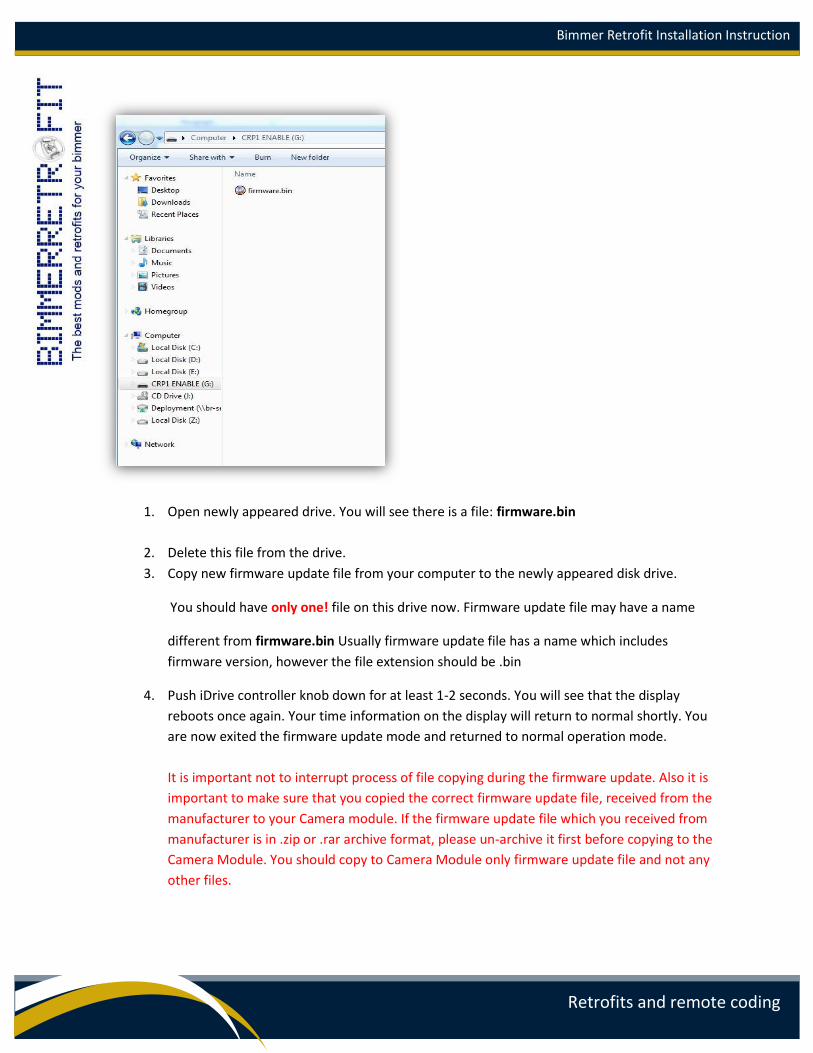
4. Open File Explorer. You will see that new disk drive appeared in the system.
Bimmer Retrofit Installation Instruction
Retrofits and remote coding
1. Open newly appeared drive. You will see there is a file: firmware.bin
2. Delete this file from the drive.
3. Copy new firmware update file from your computer to the newly appeared disk drive.
You should have only one! file on this drive now. Firmware update file may have a name
different from firmware.bin Usually firmware update file has a name which includes
firmware version, however the file extension should be .bin
4. Push iDrive controller knob down for at least 1-2 seconds. You will see that the display
reboots once again. Your time information on the display will return to normal shortly. You
are now exited the firmware update mode and returned to normal operation mode.
It is important not to interrupt process of file copying during the firmware update. Also it is
important to make sure that you copied the correct firmware update file, received from the
manufacturer to your Camera module. If the firmware update file which you received from
manufacturer is in .zip or .rar archive format, please un-archive it first before copying to the
Camera Module. You should copy to Camera Module only firmware update file and not any
other files.
Bimmer Retrofit Installation Instruction
Retrofits and remote coding
MANUAL FIRMWARE UPDATE MODE FOR THE CAMERA MODULE If for any reason your firmware update is not successful using the method above and your module can
no longer enter the firmware update mode, you can use the Manual firmware update method described
below.
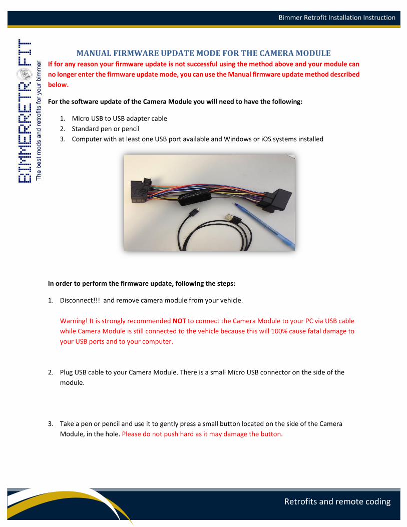
For the software update of the Camera Module you will need to have the following:
1. Micro USB to USB adapter cable
2. Standard pen or pencil
3. Computer with at least one USB port available and Windows or iOS systems installed
In order to perform the firmware update, following the steps:
1. Disconnect!!! and remove camera module from your vehicle.
Warning! It is strongly recommended NOT to connect the Camera Module to your PC via USB cable
while Camera Module is still connected to the vehicle because this will 100% cause fatal damage to
your USB ports and to your computer.
2. Plug USB cable to your Camera Module. There is a small Micro USB connector on the side of the
module.
3. Take a pen or pencil and use it to gently press a small button located on the side of the Camera
Module, in the hole. Please do not push hard as it may damage the button.
Bimmer Retrofit Installation Instruction
Retrofits and remote coding
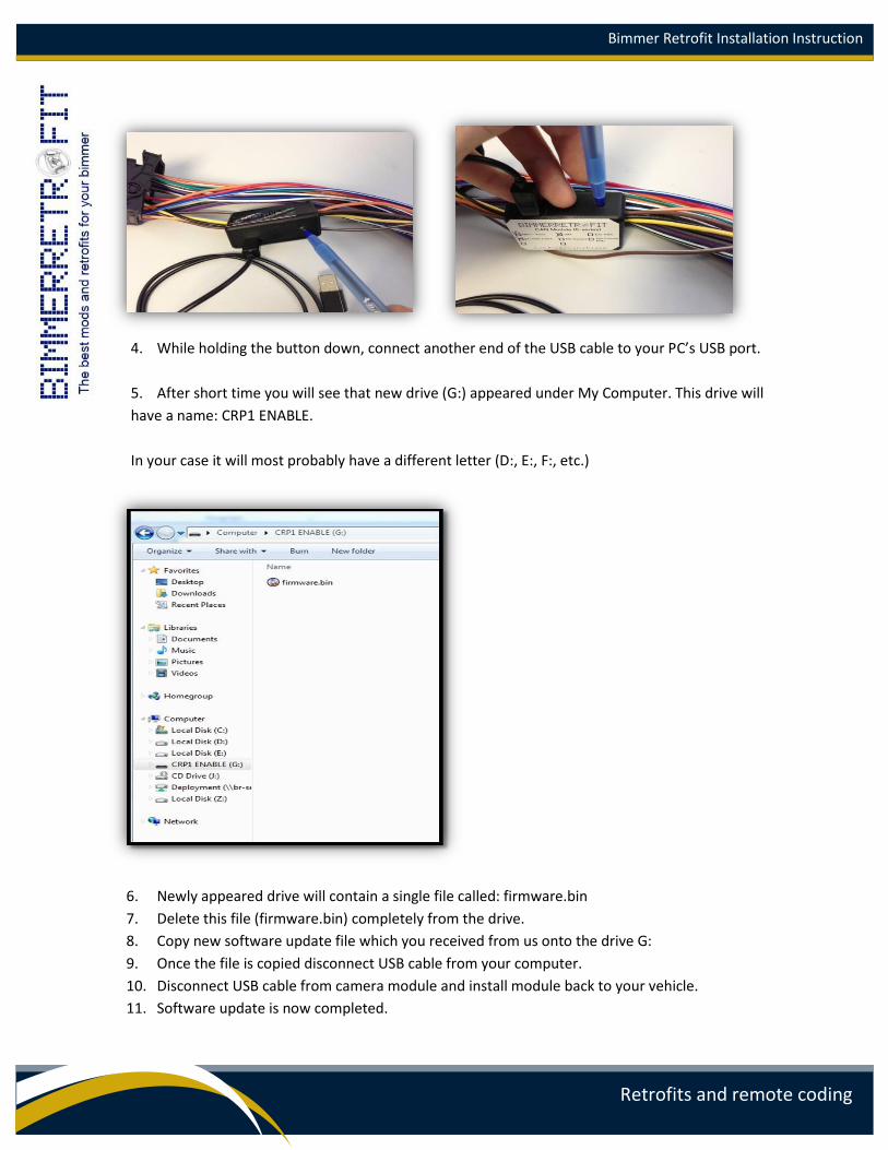
4. While holding the button down, connect another end of the USB cable to your PC’s USB port.
5. After short time you will see that new drive (G:) appeared under My Computer. This drive will
have a name: CRP1 ENABLE.
In your case it will most probably have a different letter (D:, E:, F:, etc.)
6. Newly appeared drive will contain a single file called: firmware.bin
7. Delete this file (firmware.bin) completely from the drive.
8. Copy new software update file which you received from us onto the drive G:
9. Once the file is copied disconnect USB cable from your computer.
10. Disconnect USB cable from camera module and install module back to your vehicle.
11. Software update is now completed.
Bimmer Retrofit Installation Instruction
Retrofits and remote coding
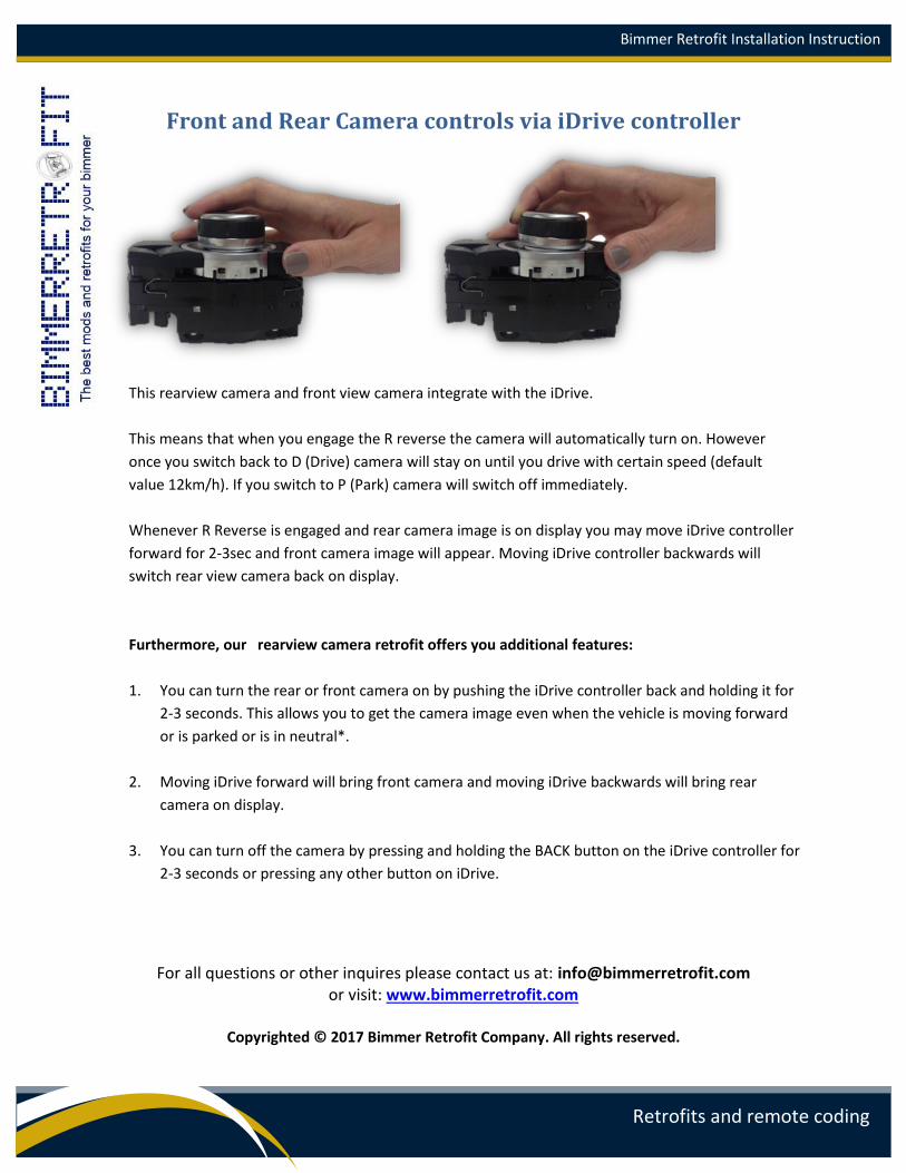
Front and Rear Camera controls via iDrive controller
This rearview camera and front view camera integrate with the iDrive.
This means that when you engage the R reverse the camera will automatically turn on. However
once you switch back to D (Drive) camera will stay on until you drive with certain speed (default
value 12km/h). If you switch to P (Park) camera will switch off immediately.
Whenever R Reverse is engaged and rear camera image is on display you may move iDrive controller
forward for 2-3sec and front camera image will appear. Moving iDrive controller backwards will
switch rear view camera back on display.
Furthermore, our rearview camera retrofit offers you additional features:
1. You can turn the rear or front camera on by pushing the iDrive controller back and holding it for
2-3 seconds. This allows you to get the camera image even when the vehicle is moving forward
or is parked or is in neutral*.
2. Moving iDrive forward will bring front camera and moving iDrive backwards will bring rear
camera on display.
3. You can turn off the camera by pressing and holding the BACK button on the iDrive controller for
2-3 seconds or pressing any other button on iDrive.
For all questions or other inquires please contact us at: [email protected] or visit: www.bimmerretrofit.com
Copyrighted © 2017 Bimmer Retrofit Company. All rights reserved.


