American Institute of Aeronautics and Astronautics
1
Realistic Near-Term Propellant Depots: Implementation of a
Critical Spacefaring Capability
Jonathan A. Goff1
Masten Space Systems, Inc., Mojave, CA, 93501
Bernard F. Kutter2 and Frank Zegler
3
United Launch Alliance, Littleton, CO, 80127
Dallas Bienhoff4
The Boeing Company, Arlington, VA, 22202
Frank Chandler5
The Boeing Company, Huntington Beach, CA 92647
Jeffrey Marchetta6
The University of Memphis, Memphis, TN, 38152
Orbital cryogenic propellant depots and the ability to refuel spacecraft in orbit are
critical capabilities for the expansion of human life throughout the Solar System. While
depots have long been recognized as an important component of large-scale manned
spaceflight efforts, questions about their technology readiness have so far prevented their
implementation. Technological advancements in settled cryogenic handling, passive thermal
control systems, and autonomous rendezvous and docking techniques make near-term
implementation of cryogenic propellant depots significantly more realistic. Current work
on flight-demonstration tools like ULA’s CRYOTE testbed, and Masten Space Systems’s
XA-1.0 suborbital RLV provide methods for affordably retiring the remaining technical
risks for cryogenic depots.
Recent depot design concepts, built on high-TRL technologies and existing flight vehicle
hardware, can enable easier implementation of first-generation propellant depots without
requiring extensive development programs. Some concepts proposed by industry include
disposable “pre-depots”, single-fluid simple depots, self-deployable dual-fluid single-launch
depots using existing launchers and near-term launcher upgrades, and multi-launch
modular depots. These concepts, particularly the dual-fluid single-launch depot enable
robust exploration and commercial transportation throughout the inner Solar System,
without the need for HLVs, while providing badly-needed markets to encourage the
commercial development of more affordable access to space.
1 Propulsion Engineer, 1570 Sabovich St. Bldg 25, AIAA Member.
2 Sr. Staff, Manager Advanced Programs, P. O. Box 277005 MS U9115, AIAA Senior Member
3 Sr. Staff, Advanced Programs, United P.O. Box 277005 MS U9115, AIAA Member
4Manager, In-Space & Surface Systems, Advanced Space Exploration, 1215 S. Clark St. MC 793C-G042, AIAA
Senior Member. 5 Director, Propulsion & Cryogenic Technologies, 5301 Bolsa Ave/H012-2B201, Associate Fellow.
6Associate Professor, Mechanical Engineering, 322D Engineering Sciences Building Memphis, TN 38152, AIAA
Member.
American Institute of Aeronautics and Astronautics
2
Nomenclature
MSS = Masten Space Systems, Inc.
ULA = United Launch Alliance
DARPA = Defense Advanced Research Projects Agency
LO2 = Liquid Oxygen
LH2 = Liquid Hydrogen
ISRU = In-Situ Resource Utilization
ISS = International Space Station
LEO = Low Earth Orbit
EML-1 = Earth-Moon L-1 LaGrange Point
EML-2 = Earth-Moon L-1 LaGrange Point
HLV = Heavy Lift Vehicle
RLV = Reusable Launch Vehicle
TRL = Technology Readiness Level
mT = 1 Metric Ton
I. Introduction
NE of the key challenges of interplanetary space travel is the vast amount of propellant that has to be hauled
from Earth to reach even the nearest bodies in the Solar System. This situation is not unique to spaceflight—
there are many historical examples of groups dealing with the challenges of operating in hostile environments far
from sources of food and fuel. Whether the challenge was crossing the frozen deserts of Antarctica with sled dogs
and skis, exploring underwater caverns in Mexico or the US military trying to operate steam-powered naval vessels
across the vast Pacific in the late 1800s, caches of supplies and fuel were a key part of solving transportation
logistics problems. For Amundsen’s South Polar expedition, caches of supplies and food were left at key points
along the way to the South Pole1. For an underwater spelunking expedition in the Huautla Plateau of Mexico, the US
Deep Caving Team established a series of supply camps at different dry points within the cavern2. For the US
Pacific Fleet, the solution was naval coaling stations and colliers located in places like Pearl Harbor, Midway Island,
Guam, and American Samoa.
The similarity of the interplanetary transportation logistics problem to its historical analogs was not lost on the
pioneers of space travel in the 20th
century. As early as 19283, scientists studying interplanetary travel began
arguing that pre-positioning propellants in orbit would be required for any sustainable large-scale travel beyond
Earth. Ever since those initial observations, the use of orbital propellant depots—facilities specifically designed to
receive, store, and dispense propellants to visiting craft—has been an important part of many of the most ambitious
transportation architecture proposals45
, including the “tanker mode” concept for Earth Orbit Rendezvous favored by
von Braun during the Apollo Program6. Perhaps one of the most valuable lessons learned from the Apollo Program
was the difficulty of making even limited sorties beyond earth orbit without using propellant depots. Launching all
of the supplies and propellant needed for exploration missions on just one rocket was only barely possible, and even
then, it only permitted voyages of a couple of weeks, at the most. One could argue that the great expense of
developing and operating the massive launch vehicles necessary for non-depot approaches is one of the principal
factors which have prevented space exploration and development activities beyond LEO since the Apollo Program
ended.
In recent years, a growing interest in commercial approaches to space transportation has led to the beginning of a
renaissance in propellant depot efforts7. In addition to the logistical advantages, researchers have begun to notice
economic benefits of orbital propellant depots. These benefits include providing demand for launch services that
can help drive down launch costs by creating a robust and competitive marketplace, providing launch demand
sufficient to encourage the development of commercial RLVs, enabling the reuse of in-space assets, and greatly
increasing the utility of future ISRU efforts8. Depots have the potential to not only greatly reduce the difficulty of
travel beyond LEO, but also to help promote the development of much more affordable and reliable means for
accessing LEO in the first place.
However, in spite of over 80 years of recognition that orbital propellant depots are a critical necessity for
affordable and sustainable travel beyond LEO, there has still been no serious effort to develop and field orbital
propellant depots. In fact, many have opposed the idea. A large part of the opposition stems from two key
misconceptions. The first of these misconceptions is that propellant depots are very technically risky and require
O

American Institute of Aeronautics and Astronautics
3
large amounts of expensive R&D work before we can even know if they will work, let alone before they can be
implemented. The second key misconception is that orbital propellant depots imply an effort comparable in
complexity to the International Space Station. Propellant depots, when viewed in this light, have often been seen as
expensive and risky detours when compared to the HLV path taken by Apollo.
Several recent developments, however, indicate that propellant depots are much closer to reality than previously
believed. While some key techniques still require demonstration, the fundamental technologies needed for initial
propellant depot capability are already at a high level of maturity. Several innovative depot design concepts have
recently been proposed, which have sufficient propellant storage capacity to enable near-term manned missions
beyond LEO, while still being much simpler than previously envisioned approaches. In addition to concepts for
simple near-term depots, several groups are now working on orbital and suborbital test-beds that will facilitate
maturation of technologies needed for initial depot capabilities and continuous improvement of propellant depot
technology. These new developments are realistic near-term options for developing and fielding these key pieces of
space transportation infrastructure.
II. Propellant Depot Technologies
An important challenge in developing space systems and architectures is determining when and how to
incorporate promising new technologies. On one hand, at least 80 percent of the life-cycle costs of a program are
determined by decisions made during the conceptual design stage9. Being too conservative about incorporating new
technologies can lock in high costs, threatening project sustainability. On the other hand, incorporation of new
technologies carries technical risk, which often makes decision makers hesitant to adopt them. An example of this
was the Apollo Program’s eventual decision to use Lunar Orbit Rendezvous (LOR). Originally, orbital rendezvous
was viewed as far too immature a technology to risk the program on. As one member of the committee that initially
rejected the LOR approach put it, “We thought it too risky. Remember, in 1961 we hadn’t even orbited Glenn yet.
We certainly had done no rendezvous yet…it had to be dead right the first time. I mean, that just seemed like a bit
much.”10
In the end, however, LOR won out in spite of the fact that orbital rendezvous technology was then only at
TRL 3 or 4. The decision was largely motivated by the political need to avoid excessive life-cycle costs and
development time for the massive Nova launch vehicle.
Propellant depot technologies now are significantly more mature than orbital rendezvous technologies were
when they were selected as the baseline for Apollo’s critical path. , Propellant depot technologies have benefited
from decades of operational experience with cryogenic upper stages and technology maturation efforts such as the
DARPA Orbital Express demonstrator. Many approaches, spanning a wide range of technological maturity, have
been investigated for key depot functions, including cryogenic fluid management, propellant thermal control, and
rendezvous, docking, and fluid coupling and transfer. . Some combinations of depot technologies can provide
initial operational capabilities with very little additional technology demonstration, while some other interesting
options will require more work. A program that utilizes incremental system demonstrations in parallel with a robust
technology maturation effort can provide early, useful operational capabilities, while still allowing some of the
promising but less developed technologies to be integrated as they reach a sufficient level of technological maturity.
A. Microgravity Cryogenic Fluid Management
The first key task of an orbital propellant depot is to store and handle fluids on orbit, particularly cryogenic
propellants. Cryogenic fluids, such as LO2 and LH2, are stored and transferred daily on Earth for use in industrial
and medical applications. Compared to the terrestrial environment, where cryogenic fluid handling is relatively
simple, the microgravity environment in which orbital propellant depots operate presents many unique challenges.
While the locations of liquids and gasses in a tank at rest in a gravity field are controlled and easily predictable, the
behavior of the fluids in microgravity is more difficult to predict and presents some unique challenges for
controlling the fluid flow. The processes of pressure venting and transfer of liquid propellant are complicated by the
uncertainty of distribution of liquid and gasses within the tank. Lack of gravity-driven buoyancy effects makes
thermal equalization within the liquid much more challenging than in even a slight gravity field. For non-volatile
propellants, the options of using either elastomeric diaphragms or surface tension liquid acquisition devices to
separate the liquid from the gas have been flight qualified. While there has been significant research on options for
dealing with these challenges for cryogenic fluids11
, the technology is less mature than for storable propellants.
American Institute of Aeronautics and Astronautics
4
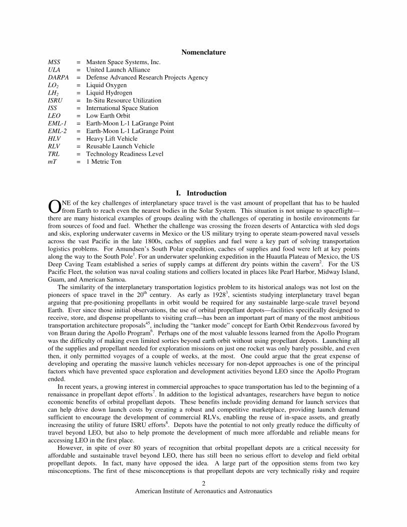
1. Inertial Propellant Settling
There are, however, alternatives to developing
techniques for manipulating fluids in microgravity,
which typically fall into the category known as settled
propellant handling. Research for cryogenic upper
stages dating back to the Saturn S-IVB and Centaur
found that providing a slight acceleration (as little as
10-4
to 10-5
g of acceleration) to the tank can make the
propellants assume a desired configuration, which
allows many of the main cryogenic fluid handling tasks
to be performed in a similar fashion to terrestrial
operations12
. The simplest and most mature settling
technique is to apply thrust to the spacecraft, forcing the
liquid to settle against one end of the tank. The thrust
can come either from small rockets or from venting a
small amount of boiled-off propellant gas through small
nozzles and can be applied periodically or continuously.
Another proposed option, which ULA plans to
flight-test in 2009 (on the DMSP-18 mission), involves
spinning the tank about its axis, as shown in Fig. 1. In
this technique, the propellant is forced against the side walls, leaving a core of gas along the axis of rotation13
. This
provides continuous settling without consuming boil-off gases.
2. Tether or Gravity Gradient Settling
Other options, which have not yet been demonstrated, use tethers or gravity gradients to provide the settling
forces. One option, similar to the centrifugal settling option mentioned previously, is to extend a tether and a
counterweight from a depot, and then to spin the assembly about its center of gravity. It is also possible to use the
same configuration without spinning the assembly, by taking advantage of the gravity gradient. Any part of the
assembly that is above the station’s center of gravity is actually travelling faster than a separate object orbiting at
that altitude, resulting in a slight acceleration outward, and any piece below the center of gravity experiences an
acceleration downward towards Earth. In order to provide adequate settling forces, the assembly only needs to be a
few hundred meters long. Another approach would use electrodynamic tethers14
both for propellantless depot
reboost as well as for propellant settling.
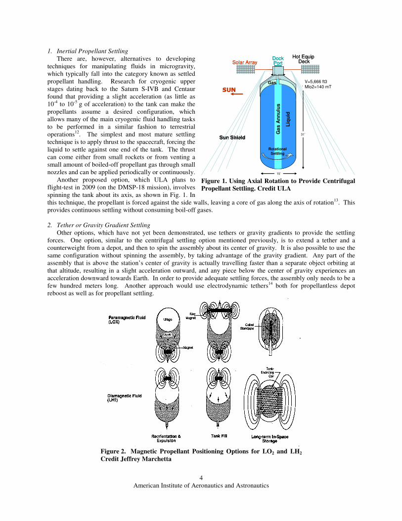
Figure 2. Magnetic Propellant Positioning Options for LO2 and LH2
Credit Jeffrey Marchetta
Ga
s A
nn
ulu
s
Gas
Sun Shield
Hot Equip Deck
DockPort
Rotational
Settling
SUN
15’
31’
V=5,666 ft3Mlo2=140 mT
Liq
uid
Solar Array
Ga
s A
nn
ulu
s
Gas
Sun Shield
Hot Equip Deck
DockPort
Rotational
Settling
SUN
15’15’
31’
V=5,666 ft3Mlo2=140 mT
Liq
uid
Solar Array
Figure 1. Using Axial Rotation to Provide Centrifugal
Propellant Settling. Credit ULA

American Institute of Aeronautics and Astronautics
5
3. Electromagnetic Propellant Settling
One particularly promising class of propellant settling options, shown above in Fig. 2, forces the fluid within the
tanks to assume a desired orientation using strong permanent or electromagnets. The settling force is provided by
the reaction of the inherent paramagnetic or diamagnetic properties of the propellants to an applied magnetic field15
.
LO2 is paramagnetic, meaning that it is slightly attracted to strong magnetic fields. LH2, methane, propane, and
other light hydrocarbons are weakly diamagnetic, meaning they are repelled by strong magnetic fields. Because the
bulk magnetic susceptibilities of the fuels are much lower than that of the LO2—with LH2 being the least susceptible
of the cryogenic fuels—the use of high temperature superconducting electromagnets may be required to make
magnetic propellant positioning for these fuels feasible. If LH2 magnetic propellant positioning is feasible, then the
same technique can be used for the more magnetically susceptible light hydrocarbons. At this moment, the
technology for electromagnetic settling is still fairly early in its development. There have been some small
experiments such as MAPO16
, which have been flown on the NASA zero-gravity airplane (Vomit Comet). Coupled
fluid/electromagnetic models were correlated to the experimental results17,18,19
. Analytical work has begun this year
using those models to determine the feasibility of using magnetic propellant positioning for tanks on the scale
required for propellant depots. If magnetic propellant positioning can be perfected, it may provide many of the
advantages of both settled and non-settled microgravity propellant handling as shown in Table 1.
Table 1. A Comparison of Cryogenic Fluid Handling Techniques
Technique Advantages Disadvantages
Zero-G Handling • Does not require reaction mass for
propellant settling.
• Integration with big stations easier
• Configuration and orientation
independent of operations
• Loading/offloading operations
identical
• Zero-G thermal control, transfer, and
liquid acquisition are low TRL.
Propulsive Settling • Settled cryo handling is high TRL,
and simplifies all other depot functions
• Settling and reboost functions can be
combined.
• Uses reaction mass for settling
• Hard to integrate with existing space
stations
• Constrains tank arrangement to get
correct settling effects
Centrifugal Settling • Does not require reaction mass for
propellant settling.
• Settled cryo handling is high TRL,
and simplifies all other depot functions
• May require despinning for docking
• May need to be combined with another
process for transfer ops
• Constrains tank arrangement to get
correct settling effects
ED Tether Settling • Provides reboost and propellant
settling without using reaction mass
• Can use zero boil-off systems
• Requires moderately large station with
significant solar power capability
• Low TRL for ED tethers
• Challenges docking
• Constrains tank arrangement to get
correct settling effects
Gravity Gradient
Settling • Does not require reaction mass for
propellant settling
• Requires very long tether and large
overall system
• Complex system dynamics
• Constrains tank arrangement to get
settling effects correctly
Electromagnetic
Settling • Does not require reaction mass for
propellant settling.
• Provides more control over propellant
positioning.
• More flexibility on tank arrangements
and depot layout
• Electromagnetic settling is low TRL
• Superconducting electromagnets may add
significant weight
• Uncertainty if existing electromagnets
sufficient for large LH2 tank settling.
American Institute of Aeronautics and Astronautics
6
Propulsive propellant settling is a well understood process and can be easily incorporated into near-term
propellant depots. As the more advanced inertial and electromagnetic approaches are technologically matured, they
can be brought into service alongside of, or in place of, the first generation depots.
B. Propellant Thermal Control
The second task of an orbital propellant depot is to store the propellants for long durations with minimal or no
boil-off losses. Due to the very low boiling points of cryogenic propellants, care must be taken to reduce the flow of
heat into the propellants and remove the heat that does make it into the propellants. Current flight-demonstrated
thermal control systems for cryogenic upper stages have not yet reached the efficiencies necessary for a reasonable
propellant depot, however many of the insulation and cooling technologies have been developed to the point of
preliminary ground-systems tests20
.
1. Thermal Insulation
An important part of the thermal control involves isolating the propellants from internal and external heat
sources. The main source of external heat load is, of course, the Sun itself. Planetary bodies, however, can also be
significant sources of radiant heat for depots in low-orbits. There are also heat sources internal to the depot, such as
electronics and power generation equipment, which must be isolated from the propellant section of the depot. For
LO2/LH2 systems, the other main heat source is the temperature difference between the two propellants.
A wide variety of passive insulation techniques have been investigated21
. Multi-Layer Insulation (MLI) material
and deployable sunshades22,23
reduce the heat flux from external sources. Vacuum Insulation Panels (VIPs), which
see extensive use in other industrial applications, and low-conductivity attachments, are also being considered for
cutting down on heat flow between the tanks and between the tanks and the depot electronics. MLI has seen
extensive operational use on satellites and space probes, and sunshades are becoming popular for space telescopes
(e.g. Spitzer, Kepler and the James Webb Space Telescope), some of which need to maintain liquid helium
temperatures at their optics for several years at a time24
. Low-conductivity mounts are currently used in some places
on upper stages, and vacuum insulation panels are being ground tested for eventual use on propellant tank common
bulkheads and in other locations.
2. Heat Rejection and Active Thermal Control
Even the best insulation system, however, still allows some heat to flow into the propellants. The simplest
method of dealing with the heat flow is to let the cryogen absorb the tank heating, resulting in a warming of the
liquid. This is what is currently done on Centaur’s LO2 tank, which is not vented on orbit. This method, however, is
usable only for medium durations, because as the heat flow into the propellants, the pressure in the tank increases,
which can eventually lead to tank rupture if unrelieved. Another approach for dealing with the heat flow into the
propellants is to allow a small amount of the propellant to boil-off, and then vent the excess gas overboard, as has
been and is done on Saturn S-IVB, the Centaur LH2 tank and the Delta IV upper stage. Not only does this process
carry away excess heat from the propellant, and keep the tanks within their structural limits, but the process of
venting the gases to space can also be used for propulsive settling of the propellants as well as for depot station-
keeping.
Some more advanced techniques have been proposed that would use the vented gas from the coldest propellant
tanks to remove heat from the overall system. This is especially useful for LO2/LH2 systems, because the LH2 has
over ten times the heat capacity of the LO2. It also starts off at a much cooler temperature, and makes up a much
smaller fraction of the overall propellant mass. By using the LH2 boil-off to cool the LO2 tank, LO2 boil-off can be
completely eliminated. This is much more mass efficient than allowing them both to boil and vent. It is also
possible, using a Thermodynamic Venting System (TVS), to use the vented hydrogen gas to remove some more heat
from its own tank. This is done by running the moderate-pressure boil-off gas through a Joule-Kelvin valve, which
drops both the pressure and temperature of the vented gas, allowing it to provide some extra cooling for the LH2
tank before it is used for removing heat from the other tanks and subsystems in the depot. After cooling the LO2
tank, and the connection between the LO2 tank and the electronics section of the depot, the now much warmer
gaseous hydrogen can be run through a nozzle to provide thrust for settling and station-keeping. While these passive
boil-off venting techniques do result in the loss of valuable propellant mass, the amount of propellant lost to boil-off
in a system with good thermal insulation may actually be less than the amount required for station-keeping. This
means that unless some higher Isp or non-propellant means (such as an electrodynamic tether) is used for station-
keeping, the propellant loss to boil-off may actually be “free”.
The other approach to heat rejection is using an active cryocooler to pump heat out of the propellants. Although
almost all cryogenic fluid cooling in space to-date has been of the passive variety, there has been significant research
American Institute of Aeronautics and Astronautics
7
into active cooling techniques due to their promise for zero boil-off operations. While zero boil-off depots are not
required for initial operations, they represent a significant enabler of longer-duration deep space missions. They
also make a lot of sense when used in conjunction with non-propulsive propellant settling where propulsive station-
keeping is not necessary. Active cryocooling eliminates the waste of propellants currently required for chill-down
operations during transfer, increases system efficiency by eliminating boil-off of propellants over time, and makes it
possible to keep the region around the depot clear of contamination. These benefits make cryocooling technologies
well worth further development effort.
C. Rendezvous, Docking, and Propellant Transfer
The last major task of an orbital propellant depot is the transfer of propellant from visiting tankers into the depot
and from the depot into customer spacecraft. This involves rendezvous and mating of the visiting vehicles, secure
attachment of fluid couplings, and safe and efficient transfer of propellants through those couplings. This process
was first demonstrated operationally by the Soviet space program in 1978 using storable propellants25
and is used
routinely for propellant resupply of the ISS by the Russian Progress vehicle and the ESA Automated Transfer
Vehicle. It has also been demonstrated recently in the US by the DARPA Orbital Express program, also with
storable propellants.
While there has not yet been an operational demonstration of cryogenic propellant transfer between two vehicles
on orbit, a similar process has been used to transfer propulsively-settled cryogenic propellants from the tanks to the
engines for every multi-burn cryogenic upper stage since the Saturn S-IVB. The experience obtained from literally
hundreds of such upper stage engine restarts—which are arguably even more finicky about two-phase flow than a
depot—is a significant knowledge base from which propellant depot designers should be able to draw. The only
piece of hardware that has not yet been flight demonstrated is the automatic connection of cryogenic fluid couplings
on orbit.
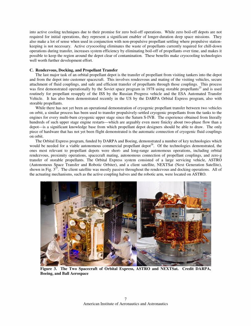
The Orbital Express program, funded by DARPA and Boeing, demonstrated a number of key technologies which
would be needed for a viable autonomous commercial propellant depot26
. Of the technologies demonstrated, the
ones most relevant to propellant depots were short- and long-range autonomous operations, including orbital
rendezvous, proximity operations, spacecraft mating, autonomous connection of propellant couplings, and zero-g
transfer of storable propellants. The Orbital Express system consisted of a large servicing vehicle, ASTRO
(Autonomous Space Transfer and Robotic Orbiter), and a client satellite, NEXTSat (Next Generation Satellite),
shown in Fig. 327
. The client satellite was mostly passive throughout the rendezvous and docking operations. All of
the actuating mechanisms, such as the active coupling halves and the robotic arm, were located on ASTRO.
Figure 3. The Two Spacecraft of Orbital Express, ASTRO and NEXTSat. Credit DARPA,
Boeing, and Ball Aerospace

American Institute of Aeronautics and Astronautics
8
The propellant transfer system, Fig. 4, transferred
storable propellants, including both hydrazine and
pressurant gas28
, at ambient temperatures. The
pressurant gas was transferred to provide ullage
equalization and to demonstrate gaseous fluid transfer.
There were 15 successful propellant transfers with
varying ullage termination quantities up to and
including a full tank load. These operations validated
the essential techniques required for safe autonomous
transfer of fluids on-orbit. While the couplings will
probably be different for cryogenic fluid transfer,,the
techniques and procedures demonstrated during the
storable fluid transfer testing can used in cryogenic
applications.
One promising approach to cryogenic fluid
couplers, proposed by ULA for depot applications, is a
coupling based on the slip-joint duct used in the LO2
feed line of the Atlas Centaur upper stage29
. The slip
joint duct, shown in Fig. 5, consists of two concentric
tubes with a set of redundant cryogenic spring-energized Teflon dynamic seals and a set of low-friction guide
bushings, all arranged in an annulus between the inner and outer tube. This system would be combined with shutoff
valves on both sides of the connection to prevent leakage when the connection is broken. With proper design, this
coupling can be self aligning, and the seal does not require large clamping forces to provide a leak-tight connection;
only axial restraint is needed to resist pressure and fluid dynamic forces. The coupling also has a very low thermal
mass, and can provide much larger flow area for a given sized coupling than other cryogenic couplings, resulting in
faster fluid transfer times.
Figure 5. Illustration of a Slip-Joint Duct Connector for Cryogenic Propellant Transfer. Credit ULA
Figure 4. Fluid Coupling Placement between ASTRO
and NEXTSat. Credit DARPA and Boeing

American Institute of Aeronautics and Astronautics
9
Another contribution of the Orbital Express project to the development of propellant depots is the concept of
using a space tug to simplify proximity ops and propellant transfer coupling connection. The main previous
example of orbital propellant transfer, the Progress spacecraft, required the tanker vehicle to be a fully maneuverable
proximity operations craft in its own right. This resulted in a very poor payload to spacecraft mass ratio—only 31%
of the launched mass was usable payload. While it may be possible to design a more mass efficient tanker system
based on the COTS cargo vehicles, and to minimize tanker “over head” performance loss through efficient tanker
design30
or by directly integrating the fluid load into the upper stage tanks, the parasitic mass of tanker docking and
transfer systems still have to be taken into consideration for any depot architecture design.
However, the success of the Orbital Express program suggests that the delivered propellant mass fraction can be
further increased by offloading most of the rendezvous and docking hardware to a reusable space tug31
. Such an
orbital tug system, when combined with an upper stage capable of station-keeping, would require only very minimal
hardware on the delivery tanker. In operation, such a tug could leave the depot, rendezvous with the tanker and
upper stage, mate to the tanker, remove the tanker from the upper stage, haul the tanker to the depot, attach
propellant feedlines, and then dispose of the tanker after all the propellant has been transferred. This would allow
the tanker to be a lot simpler, requiring only passive mating and propellant coupling hardware, and some simple
controls. Offloading the expensive “smarts” to a reusable tug, which remains in orbit between missions, should
reduce the cost of delivery tankers substantially. The creation of a standardized mating and transfer interface would
also allow multiple US and international launch companies to supply propellants to an orbital depot. These
relatively dumb tankers would mostly consist of tanks sized to the launch vehicles that would be lofting them. A
tanker could be built using similar construction to the launch vehicle’s upper stage or even integrated directly into
the upper stage32
, with the addition of the mating and propellant transfer interface panel. The use of dumb tankers
would permit a healthy amount of competition for propellant deliveries, which will provide a strong incentive for
lowering prices over time.
III. Near-term Propellant Depot Concepts
While many depot concepts have been proposed which involve complex assembly operations on par with the
contsruction of ISS, several innovative but simpler concepts have been recently proposed. These concepts provide
enough capability to be immediately useful without requiring excessive up-front development, and can be evolved
as the demand for higher flight-rates and additional services increase.
A. ULA Disposable Single-Use “Pre-Depot” Concept The most straightforward propellant depot consists of a delivery
tanker cryogenic supply tank, as in Fig. 6, modified with modest thermal
insulation. Such a supply tank is designed specifically as part of a
delivery tanker used for resupplying an orbital propellant depot.
However, with modest thermal protection, such a tank can support
months of near zero boil-off by taking advantage of the thermal
capacitance of the launched propellant. This disposable “pre-depot” can
be pre-launched and then used to directly supply propellant to a
propulsion stage. To reduce development costs, the depot tank can be a
derivative of existing upper stage tanks such as Centaur’s 3m diameter
LO2 tank. Existing boosters, such as the Atlas V 551 or the RS-68A
equipped Delta-IV Heavy, allow a “pre-depot” with as much as 20-26mT
of LO2 capacity. For launch, the disposable “pre-depot” is stacked on the
launch vehicle using standard payload interfaces.
To minimize heating, the tank has minimum penetrations. Avionics,
docking port, reaction control system and fluid control are all mounted on
the composite, low conductivity payload adapter. The entire system is
shrouded in a thick MLI blanket, possibly further protected with a conic
sunshield. By saturating the cryogenic propellant at atmospheric
pressure prior to lift-off and allowing the bulk vapor pressure to slowly
increase, the propellant can passively absorb tank heating for months with minimal need for tank venting. This
period of minimal boil-off can be nearly doubled with pre-launch subcooling to just above the freezing point of the
LO233
.
Figure 6. A Lightweight, Disposable
“Pre-Depot” Tank, Derived from
Centaur LO2 Tank, with 26 mT LO2
Capacity. Credit ULA
American Institute of Aeronautics and Astronautics
10
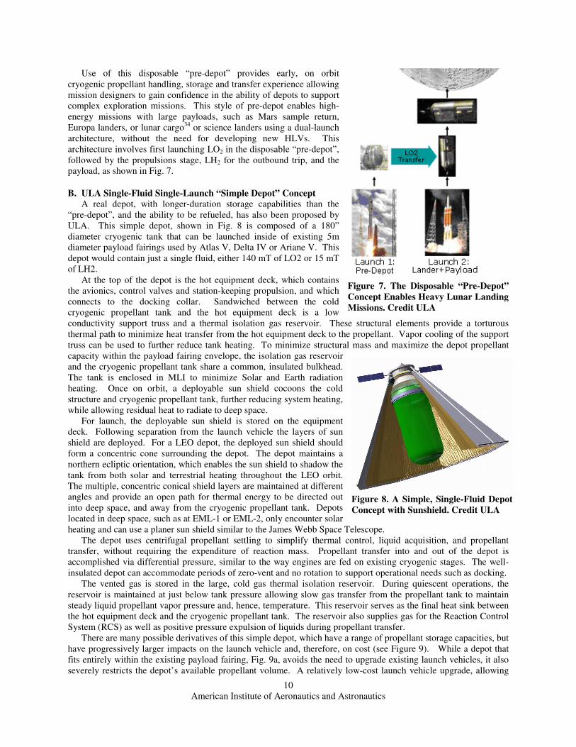
Use of this disposable “pre-depot” provides early, on orbit
cryogenic propellant handling, storage and transfer experience allowing
mission designers to gain confidence in the ability of depots to support
complex exploration missions. This style of pre-depot enables high-
energy missions with large payloads, such as Mars sample return,
Europa landers, or lunar cargo34
or science landers using a dual-launch
architecture, without the need for developing new HLVs. This
architecture involves first launching LO2 in the disposable “pre-depot”,
followed by the propulsions stage, LH2 for the outbound trip, and the
payload, as shown in Fig. 7.
B. ULA Single-Fluid Single-Launch “Simple Depot” Concept
A real depot, with longer-duration storage capabilities than the
“pre-depot”, and the ability to be refueled, has also been proposed by
ULA. This simple depot, shown in Fig. 8 is composed of a 180”
diameter cryogenic tank that can be launched inside of existing 5m
diameter payload fairings used by Atlas V, Delta IV or Ariane V. This
depot would contain just a single fluid, either 140 mT of LO2 or 15 mT
of LH2.
At the top of the depot is the hot equipment deck, which contains
the avionics, control valves and station-keeping propulsion, and which
connects to the docking collar. Sandwiched between the cold
cryogenic propellant tank and the hot equipment deck is a low
conductivity support truss and a thermal isolation gas reservoir. These structural elements provide a torturous
thermal path to minimize heat transfer from the hot equipment deck to the propellant. Vapor cooling of the support
truss can be used to further reduce tank heating. To minimize structural mass and maximize the depot propellant
capacity within the payload fairing envelope, the isolation gas reservoir
and the cryogenic propellant tank share a common, insulated bulkhead.
The tank is enclosed in MLI to minimize Solar and Earth radiation
heating. Once on orbit, a deployable sun shield cocoons the cold
structure and cryogenic propellant tank, further reducing system heating,
while allowing residual heat to radiate to deep space.
For launch, the deployable sun shield is stored on the equipment
deck. Following separation from the launch vehicle the layers of sun
shield are deployed. For a LEO depot, the deployed sun shield should
form a concentric cone surrounding the depot. The depot maintains a
northern ecliptic orientation, which enables the sun shield to shadow the
tank from both solar and terrestrial heating throughout the LEO orbit.
The multiple, concentric conical shield layers are maintained at different
angles and provide an open path for thermal energy to be directed out
into deep space, and away from the cryogenic propellant tank. Depots
located in deep space, such as at EML-1 or EML-2, only encounter solar
heating and can use a planer sun shield similar to the James Webb Space Telescope.
The depot uses centrifugal propellant settling to simplify thermal control, liquid acquisition, and propellant
transfer, without requiring the expenditure of reaction mass. Propellant transfer into and out of the depot is
accomplished via differential pressure, similar to the way engines are fed on existing cryogenic stages. The well-
insulated depot can accommodate periods of zero-vent and no rotation to support operational needs such as docking.
The vented gas is stored in the large, cold gas thermal isolation reservoir. During quiescent operations, the
reservoir is maintained at just below tank pressure allowing slow gas transfer from the propellant tank to maintain
steady liquid propellant vapor pressure and, hence, temperature. This reservoir serves as the final heat sink between
the hot equipment deck and the cryogenic propellant tank. The reservoir also supplies gas for the Reaction Control
System (RCS) as well as positive pressure expulsion of liquids during propellant transfer.
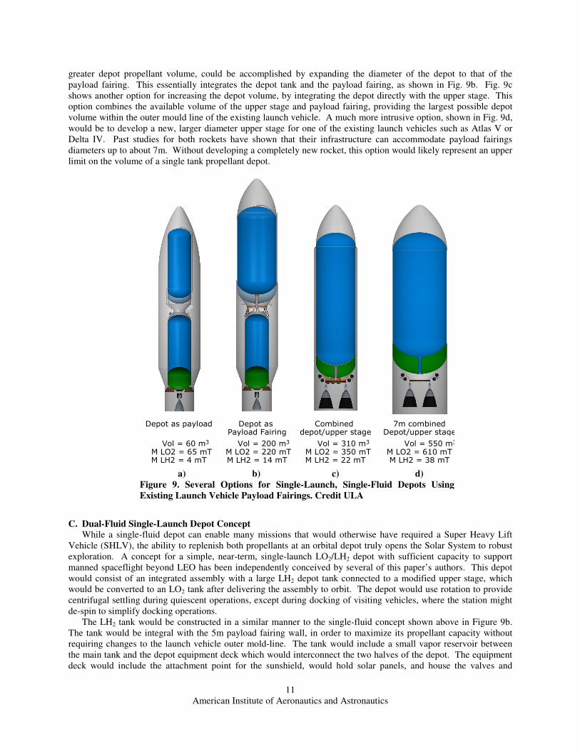
There are many possible derivatives of this simple depot, which have a range of propellant storage capacities, but
have progressively larger impacts on the launch vehicle and, therefore, on cost (see Figure 9). While a depot that
fits entirely within the existing payload fairing, Fig. 9a, avoids the need to upgrade existing launch vehicles, it also
severely restricts the depot’s available propellant volume. A relatively low-cost launch vehicle upgrade, allowing
Figure 7. The Disposable “Pre-Depot”
Concept Enables Heavy Lunar Landing
Missions. Credit ULA
Figure 8. A Simple, Single-Fluid Depot
Concept with Sunshield. Credit ULA
American Institute of Aeronautics and Astronautics
11
greater depot propellant volume, could be accomplished by expanding the diameter of the depot to that of the
payload fairing. This essentially integrates the depot tank and the payload fairing, as shown in Fig. 9b. Fig. 9c
shows another option for increasing the depot volume, by integrating the depot directly with the upper stage. This
option combines the available volume of the upper stage and payload fairing, providing the largest possible depot
volume within the outer mould line of the existing launch vehicle. A much more intrusive option, shown in Fig. 9d,
would be to develop a new, larger diameter upper stage for one of the existing launch vehicles such as Atlas V or
Delta IV. Past studies for both rockets have shown that their infrastructure can accommodate payload fairings
diameters up to about 7m. Without developing a completely new rocket, this option would likely represent an upper
limit on the volume of a single tank propellant depot.
C. Dual-Fluid Single-Launch Depot Concept
While a single-fluid depot can enable many missions that would otherwise have required a Super Heavy Lift
Vehicle (SHLV), the ability to replenish both propellants at an orbital depot truly opens the Solar System to robust
exploration. A concept for a simple, near-term, single-launch LO2/LH2 depot with sufficient capacity to support
manned spaceflight beyond LEO has been independently conceived by several of this paper’s authors. This depot
would consist of an integrated assembly with a large LH2 depot tank connected to a modified upper stage, which
would be converted to an LO2 tank after delivering the assembly to orbit. The depot would use rotation to provide
centrifugal settling during quiescent operations, except during docking of visiting vehicles, where the station might
de-spin to simplify docking operations.
The LH2 tank would be constructed in a similar manner to the single-fluid concept shown above in Figure 9b.
The tank would be integral with the 5m payload fairing wall, in order to maximize its propellant capacity without
requiring changes to the launch vehicle outer mold-line. The tank would include a small vapor reservoir between
the main tank and the depot equipment deck which would interconnect the two halves of the depot. The equipment
deck would include the attachment point for the sunshield, would hold solar panels, and house the valves and
Depot as payload
Vol = 60 m3
M LO2 = 65 mTM LH2 = 4 mT
Depot as Payload Fairing
Vol = 200 m3
M LO2 = 220 mTM LH2 = 14 mT
Combined depot/upper stage
Vol = 310 m3
M LO2 = 350 mTM LH2 = 22 mT
7m combinedDepot/upper stage
Vol = 550 m3
M LO2 = 610 mTM LH2 = 38 mT
a) b) c) d)
Figure 9. Several Options for Single-Launch, Single-Fluid Depots Using
Existing Launch Vehicle Payload Fairings. Credit ULA

American Institute of Aeronautics and Astronautics
12
controls for the LH2 half of the depot. The depot equipment deck would be attached to the LH2 tank and the LO2
tanks via low-conductivity materials.
The LO2 half of the depot would be constructed by adding several mission-specific modifications to the upper
stage used to orbit the vehicle. These additions would include MLI to provide in-space thermal insulation, docking
adapters and transfer interfaces mounted on the aft end of the stage, and some additional plumbing and controls for
depot operations. The stage would be converted to LO2 use after arriving at the destination orbit by first transferring
any remaining LH2 from the upper stage LH2 tank into the much larger depot LH2 tank. The upper stage LH2 tank
would then be vented to verify that no residual hydrogen remained. After allowing it to sit open to vacuum for some
time, the tank would be resealed and any remaining LO2 from the upper stage would be transferred from the upper
stage LO2 tank into the now-empty upper stage LH2 tank. The emptied upper stage LO2 tank would then serve as
the gas barrier to insulate the LO2 tank from heat flowing out of the aft section. For thermal control, the LO2 section
would take advantage of the fact that LH2 has a heat capacity ten times higher than LO2. By using the boiled
hydrogen to chill the LO2 tank and the interconnects between the tanks and hot structures, the depot would be able to
completely suppress LO2 boil-off, even though the LO2 section would not include its own sunshield, and in spite of
the rather severe thermal environment in LEO. As mentioned previously, the LH2 boil-off in this situation is still
less than the reaction mass requirements for station-keeping, so none of the boil-off LH2 is actually wasted.
An illustration of such a depot, based on the ULA ACES upper stage35
is shown below in Fig. 10. Using the
ACES stage, the depot would hold 121 mT of propellant (106 mT of LO2 and 15 mT of LH2). It should be noted
however, that this concept could also be based on existing stages such as the Centaur or Delta-IV Heavy upper
stages, or other proposed LO2/LH2 upper stages such as SpaceX’s Raptor, or Arianespace’s Ariane 5 ESC-B. A
depot using a stock Centaur as its LO2 tank would be able to hold about 52mT of LO2 and 14mT of LH2. The
resulting oxidizer to fuel (O/F) ratio is 3.7, which is far richer than the 5.5-6:1 ratio typical for existing upper stages,
in which only about 62mT of propellant would be usable. However, by stretching the Centaur stage LH2 tank by
about 1.5m (and shortening the depot tank by the same amount to keep it within the boundaries of the existing
fairings), the total propellant loads become about 64mT of LO2 and 12mT of LH2, giving a more useful O/F ratio of
5.4. This would leave some extra LH2 tankage to handle the higher boil-off. Tank barrel stretches are far less
expensive than changes to the diameter of the tanks, which require redesigning the complicated aft-end of the rocket,
new tooling and qualification testing. In fact, many of the upgrades to the Centaur stage over the years have
consisted of such barrel stretching36
.
Figure 10. A Single Launch, Dual-Fluid Propellant Depot. Credit ULA
American Institute of Aeronautics and Astronautics
13
By combining a depot tank with a propulsive stage, this depot concept is able to self-deploy to locations beyond
LEO, such as at EML-1 or -2, or even as far as Mars orbit. By placing one of these depots in LEO and one in either
EML-1 or -2, ESAS-class lunar missions can be performed without requiring vehicles bigger than existing
launchers, and without requiring a new Earth departure stage. The severe thermal environment in LEO causes a
substantial amount of propellant boil-off over the course of a year. EML-1 or -2 depots are in a much more benign
thermal environment, with very low boil-off levels. This leads to the conclusion that the best way to use a depot
system like this is to forward propellants on from the LEO depot to the EML-1 or -2 depot as quickly as possible.
The higher the tempo of flights beyond LEO, the lower the percentage of propellants lost to boil-off in LEO. With a
decent operational tempo, boil-off losses for this system can be kept to low single-digit percentages of the yearly
propellant throughput.
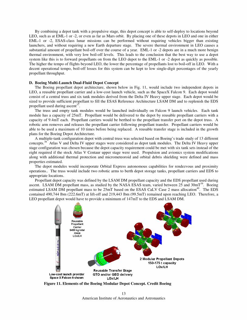
D. Boeing Multi-Launch Dual-Fluid Depot Concept
The Boeing propellant depot architecture, shown below in Fig. 11, would include two independent depots in
LEO, a reusable propellant carrier and a low-cost launch vehicle, such as the SpaceX Falcon 9. Each depot would
consist of a central truss and six tank modules derived from the Delta IV Heavy upper stage. Each depot would be
sized to provide sufficient propellant to fill the ESAS Reference Architecture LSAM DM and to replenish the EDS
propellant used during ascent37
.
The truss and empty tank modules would be launched individually on Falcon 9 launch vehicles. Each tank
module has a capacity of 25mT. Propellant would be delivered to the depot by reusable propellant carriers with a
capacity of 9.4mT each. Propellant carriers would be berthed to the propellant transfer port on the depot truss. A
robotic arm removes and releases the propellant carrier following propellant transfer. Propellant carriers would be
able to be used a maximum of 10 times before being replaced. A reusable transfer stage is included in the growth
plans for the Boeing Depot Architecture.
A multiple-tank configuration depot with central truss was selected based on Boeing’s trade study of 13 different
concepts.38
Atlas V and Delta IV upper stages were considered as depot tank modules. The Delta IV Heavy upper
stage configuration was chosen because the depot capacity requirement could be met with six tank sets instead of the
eight required if the stock Atlas V Centaur upper stage were used. Propulsion and avionics system modifications
along with additional thermal protection and micrometeoroid and orbital debris shielding were defined and mass
properties estimated.
The depot modules would incorporate Orbital Express autonomous capabilities for rendezvous and proximity
operations.. The truss would include two robotic arms to berth depot storage tanks, propellant carriers and EDS to
appropriate locations.
Propellant depot capacity was defined by the LSAM DM propellant capacity and the EDS propellant used during
ascent. LSAM DM propellant mass, as studied by the NASA ESAS team, varied between 25 and 30mT39
. Boeing
estimated LSAM DM propellant mass to be 25mT based on the ESAS CaLV Case 2 mass allocation40
. The EDS
contained 490,744 lbm (222.6mT) at lift-off and 219,443 lbm (99.5mT) remained upon reaching LEO. Therefore, a
LEO propellant depot would have to provide a minimum of 147mT to the EDS and LSAM DM.
Figure 11. Elements of the Boeing Modular Depot Concept. Credit Boeing
American Institute of Aeronautics and Astronautics
14
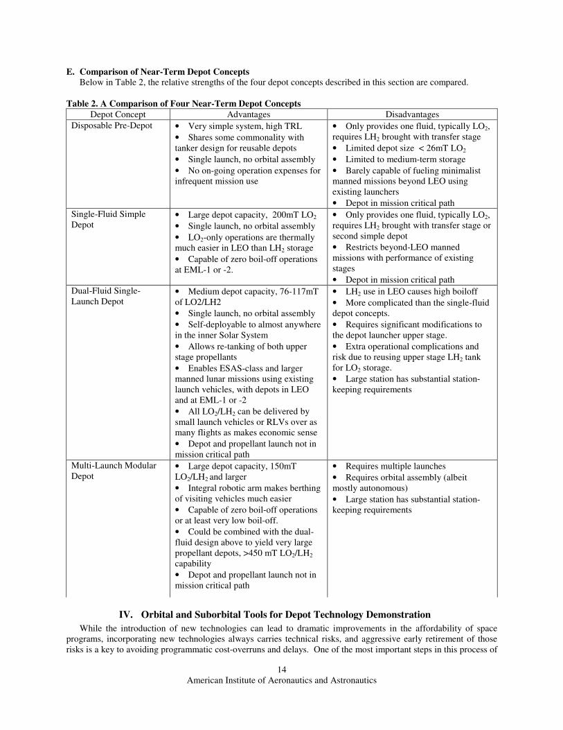
E. Comparison of Near-Term Depot Concepts
Below in Table 2, the relative strengths of the four depot concepts described in this section are compared.
IV. Orbital and Suborbital Tools for Depot Technology Demonstration
While the introduction of new technologies can lead to dramatic improvements in the affordability of space
programs, incorporating new technologies always carries technical risks, and aggressive early retirement of those
risks is a key to avoiding programmatic cost-overruns and delays. One of the most important steps in this process of
Table 2. A Comparison of Four Near-Term Depot Concepts
Depot Concept Advantages Disadvantages
Disposable Pre-Depot • Very simple system, high TRL
• Shares some commonality with
tanker design for reusable depots
• Single launch, no orbital assembly
• No on-going operation expenses for
infrequent mission use
• Only provides one fluid, typically LO2,
requires LH2 brought with transfer stage
• Limited depot size < 26mT LO2
• Limited to medium-term storage
• Barely capable of fueling minimalist
manned missions beyond LEO using
existing launchers
• Depot in mission critical path
Single-Fluid Simple
Depot • Large depot capacity, 200mT LO2
• Single launch, no orbital assembly
• LO2-only operations are thermally
much easier in LEO than LH2 storage
• Capable of zero boil-off operations
at EML-1 or -2.
• Only provides one fluid, typically LO2,
requires LH2 brought with transfer stage or
second simple depot
• Restricts beyond-LEO manned
missions with performance of existing
stages
• Depot in mission critical path
Dual-Fluid Single-
Launch Depot • Medium depot capacity, 76-117mT
of LO2/LH2
• Single launch, no orbital assembly
• Self-deployable to almost anywhere
in the inner Solar System
• Allows re-tanking of both upper
stage propellants
• Enables ESAS-class and larger
manned lunar missions using existing
launch vehicles, with depots in LEO
and at EML-1 or -2
• All LO2/LH2 can be delivered by
small launch vehicles or RLVs over as
many flights as makes economic sense
• Depot and propellant launch not in
mission critical path
• LH2 use in LEO causes high boiloff
• More complicated than the single-fluid
depot concepts.
• Requires significant modifications to
the depot launcher upper stage.
• Extra operational complications and
risk due to reusing upper stage LH2 tank
for LO2 storage.
• Large station has substantial station-
keeping requirements
Multi-Launch Modular
Depot • Large depot capacity, 150mT
LO2/LH2 and larger
• Integral robotic arm makes berthing
of visiting vehicles much easier
• Capable of zero boil-off operations
or at least very low boil-off.
• Could be combined with the dual-
fluid design above to yield very large
propellant depots, >450 mT LO2/LH2
capability
• Depot and propellant launch not in
mission critical path
• Requires multiple launches
• Requires orbital assembly (albeit
mostly autonomous)
• Large station has substantial station-
keeping requirements
American Institute of Aeronautics and Astronautics
15
space technology maturation, especially for systems involving complicated phenomena like cryogenic fluid
management, is flight testing in the space environment.41
Unfortunately, this step is often hampered by the high cost
and infrequent opportunities for flight testing. In many cases this prevents adequate experimentation with
alternative approaches to truly evaluate their feasibility. Space architectures often suffer thereby from conceptual
lock-in, where judgment decisions made during early phases with marginal and incomplete data win out over
promising new concepts42
. Recent progress in developing orbital testbeds for cryogenic fluid management and in
the fielding of commercial reusable suborbital vehicles means that a wider range of technological solutions can now
be affordably and extensively tested. These capabilities allow various propellant depot technologies to be rapidly
matured, while simultaneously increasing the probability that promising alternative technological approaches will be
adequately investigated as well.
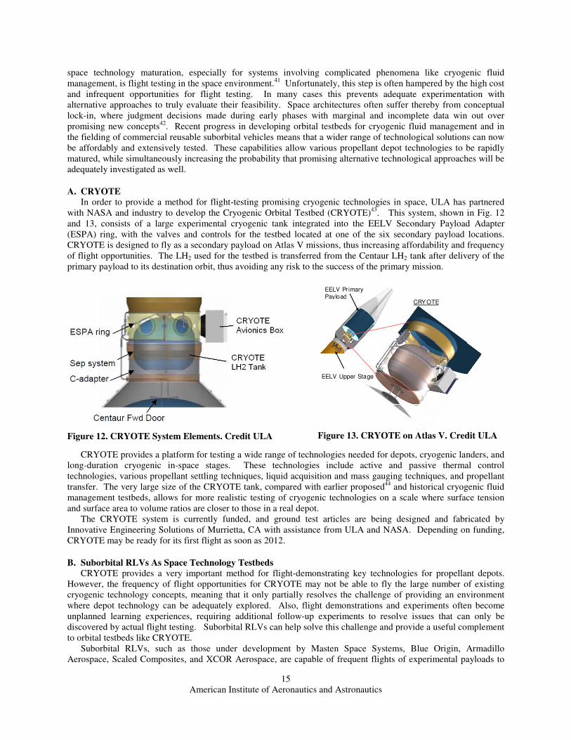
A. CRYOTE
In order to provide a method for flight-testing promising cryogenic technologies in space, ULA has partnered
with NASA and industry to develop the Cryogenic Orbital Testbed (CRYOTE)43
. This system, shown in Fig. 12
and 13, consists of a large experimental cryogenic tank integrated into the EELV Secondary Payload Adapter
(ESPA) ring, with the valves and controls for the testbed located at one of the six secondary payload locations.
CRYOTE is designed to fly as a secondary payload on Atlas V missions, thus increasing affordability and frequency
of flight opportunities. The LH2 used for the testbed is transferred from the Centaur LH2 tank after delivery of the
primary payload to its destination orbit, thus avoiding any risk to the success of the primary mission.
CRYOTE provides a platform for testing a wide range of technologies needed for depots, cryogenic landers, and
long-duration cryogenic in-space stages. These technologies include active and passive thermal control
technologies, various propellant settling techniques, liquid acquisition and mass gauging techniques, and propellant
transfer. The very large size of the CRYOTE tank, compared with earlier proposed44
and historical cryogenic fluid
management testbeds, allows for more realistic testing of cryogenic technologies on a scale where surface tension
and surface area to volume ratios are closer to those in a real depot.
The CRYOTE system is currently funded, and ground test articles are being designed and fabricated by
Innovative Engineering Solutions of Murrietta, CA with assistance from ULA and NASA. Depending on funding,
CRYOTE may be ready for its first flight as soon as 2012.
B. Suborbital RLVs As Space Technology Testbeds
CRYOTE provides a very important method for flight-demonstrating key technologies for propellant depots.
However, the frequency of flight opportunities for CRYOTE may not be able to fly the large number of existing
cryogenic technology concepts, meaning that it only partially resolves the challenge of providing an environment
where depot technology can be adequately explored. Also, flight demonstrations and experiments often become
unplanned learning experiences, requiring additional follow-up experiments to resolve issues that can only be
discovered by actual flight testing. Suborbital RLVs can help solve this challenge and provide a useful complement
to orbital testbeds like CRYOTE.
Suborbital RLVs, such as those under development by Masten Space Systems, Blue Origin, Armadillo
Aerospace, Scaled Composites, and XCOR Aerospace, are capable of frequent flights of experimental payloads to
CRY OTE
EELV Upper Stage
EELV Pr imary Payload
Figure 13. CRYOTE on Atlas V. Credit ULA
Figure 12. CRYOTE System Elements. Credit ULA

American Institute of Aeronautics and Astronautics
16
the edge of space, providing a few minutes of microgravity per flight.
These vehicles are designed to return to their launch site, where
experiments can be recovered and even reflown same-day, if necessary.
Masten Space Systems, in particular, is investigating the feasibility of
developing a suborbital version of the CRYOTE system for flight on its
XA-1.0 vehicle (shown in Fig. 14). Vertical takeoff and landing
systems, such as those being developed by MSS, Blue Origin, and
Armadillo, are particularly useful for cryogenic fluid management
experiments.. Most are capable of being flown unmanned, and they
tend to have spacious payload accommodations because wide diameters
are needed for landing stability. .Unmanned flight capability may be
important for flights involving highly flammable liquids like LH2,
because it allows the cabin atmosphere to be filled with a neutral buffer
gas like helium. The high flight rate capability of these vehicles, combined with the lower cost of accessing
suborbital space makes it easier to explore a wider range of alternative depot-enabling technologies. Also, by
substantially lowering the cost of failure, suborbital RLVs allow experimentation to be done in a rapid, iterative
process, as is typical in non-space technology development projects. By trying out technologies and experimental
hardware earlier in the development process, knowledge can be gained less expensively and costly detours can be
avoided.
Suborbital vehicles do not provide the same long-duration flight capability that may be necessary to ultimately
demonstrate a complete, integrated depot system. However, by allowing earlier experimentation, and by allowing
CRYOTE payloads to be tested out before being committed to an expensive orbital mission, they can provide a great
enhancement to the capabilities provided by CRYOTE.
V. Conclusion
While there is still work to be done to bring orbital propellant depots into reality, the technology is at the point
where it can be incorporated into manned space transportation systems and be moved forward. The depot design
concepts discussed in this paper offer realistic, near-term options that would be useful in a wide variety of manned
exploration missions, and would enable commercial manned spaceflight beyond LEO. The tools being developed for
flight-testing and maturing these propellant depot technologies make propellant depots much closer to reality than
they have ever been. Depots are a key capability for a spacefaring civilization that are ready for development today.
References
1 Amundsen, R. “The South Pole: An Account of the Norwegian Antarctic Expedition in the ‘Fram’, 1910-1912”
Interlink Publishing Group, 2003. Chapter VI: Depot Journeys. 2 Stone, W. C., "The Challenge of the Pena Colorada," No. 14, September 1984, pp. 46-55, AMCS Activities
Newsletter, Association for Mexican Cave Studies, Box 7672, Austin, TX 78713 3 Sykora, Fritz, “Guido von Pirquet-Austrian Pioneer of Astronautics,” History of Rocketry and Astronautics, R.
Cargill Hall, ed., AAS Publications, San Diego, 1986, p. 151. 4 Wilson, D. J.; Hale, D. V.; Whitacre, W. E. “Orbital propellant depot system” (Cryogenic Engineering Conference,
Boulder, Colo., June 17-19, 1970.) In: Advances in cryogenic engineering. Volume 17 (A72-3882619-33) New
York, Plenum Press, 1972, p. 160-165. 5 Flemming, Ken. “STV fueling options” in NASA, Washington, Beyond the Baseline 1991: Proceedings of the
Space Station Evolution Symposium. Volume 1: Space Station Freedom, Part 2 p 489-531 (SEE N92-17409 08-18) 6 Von Braun, W. “Concluding Remarks by Dr. Wernher von Braun about Mode Selection for the Lunar Landing
Program”, 7 June 1962, Lunar-Orbit Rendezvous File, NASA Historical Reference Collection, NASA Headquarters,
Washington D.C. p. 7 7 Kutter, Bernard. “Commercial Launch Services: An Enabler for Launch Vehicle Evolution and Cost Reduction”,
AIAA-2006-7271. 8 Goff, J., Traugott, S., and Oesterle, A. “Depot-Centric Human Spaceflight”. Whitepaper submitted to the Review
of US Human Spaceflight Plans Committee, July 2009.
http://www.nasa.gov/pdf/376490main_026%20-%2020090722.2.Depot-Centric_Human_Spaceflight.pdf 9 Blair, J.C., Ryan, R.S., Schutzenhofer, L.A., Humphries, W.R. “Launch Vehicle Design Process: Characterization,
Technical Integration, and Lessons Learned”. NASA/TP-2001-210992. p. 35.
Figure 14. XA-1.0 Suborbital RLV.
Credit MSS
American Institute of Aeronautics and Astronautics
17
10
Hansen, James R., “Enchanted Rendezvous, ” Monographs in Aerospace History, Series #4, NASA Headquarters
History Office, January 1999, pp. 30. 11
LeBar, J., and Cady, E., “The Advanced Cryogenic Evolved Stage (ACES)—A Low-Cost, Low-Risk Approach to
Space Exploration Launch”. AIAA-2007-7454. September, 2007.
http://www.ulalaunch.com/docs/publications/TheAdvancedCryogenicEvolvedStageACES2006LeBar7454.pdf 12
Jeffrey S. De Kruif, “Centaur Upperstage Applicability for Several-Day Mission Durations with Minor Insulation
Modifications”, AIAA-2007-5845, July 2007,
http://www.ulalaunch.com/docs/publications/CentaurUpperstageApplicabilityforSeveralDayMissionDurationswith
MinorInsulationModificationsAIAA20075845.pdf. 13
Bernard Kutter, “A Practical, Affordable Cryogenic Propellant Depot based on ULA’s Flight Experience”, AIAA
2008-7644, September 2008,
http://www.ulalaunch.com/docs/publications/APracticalAffordableCryogenicPropellantDepotBasedonULAsFlightE
xperience20087644.pdf 14
Bonometti, J., Sorensen, K., Jansen, R., Dankanich, J., and Frame, K. “Free Re-boost Electrodynamic Tether on
the International Space Station”. AIAA-2005-4545. July 2005. 15
Marchetta, J.G., Simmons, B.D., Hochstein, J.I., "Magnetic Retention of LO2 in an Accelerating Environment,"
Acta Astronautica, Vol. 62, 8-9, pp.478-490, April-May 2008. 16
Martin, J.J., Holt, J.B. “Magnetically Actuated Propellant Orientation Experiment, Controlling Fluid Motion with
Magnetic Fields in a Low-Gravity Environment.” NASA TM 210129. 17
Marchetta, J.G., Roos, K.M., "Simulating Magnetic Positive Positioning of Cryogenic Propellants in a Transient
Acceleration Field,"Computers and Fluids, Sept. 2008,DOI: 10.1016/j.compfluid.2008.09.005. 18
Marchetta, J.G., "Simulation of LOX Reorientation Using Magnetic Positive Positioning," Microgravity Science
and Technology Journal, Vol. 18, pp. 31-39, 2006. 19
Marchetta J.G., Hochstein, J.I., "Simulation and Prediction of Magnetic Propellant Reorientation in Reduced
Gravity", AIAA Journal of Propulsion and Power, Vol. 20, no. 5, pp.927-935, September-October 2004. 20
J. J. Martin, “Large-Scale Liquid Hydrogen Testing of a Variable Density Multilayer Insulation With a Foam
Substrate”, NASA/TM-2001-211089, June 2001. 21
Kutter et al. “Atlas Centaur Extensibility to Long-Duration In-Space Applications”, AIAA 2005-6738, Sept 2005,
http://www.ulalaunch.com/docs/publications/AtlasCentaurExtensibilitytoLongDurationInSpaceApplications200567
38.pdf 22
Dew, M. et al., “Design and Development of an In-Space Deployable Sun Shield for the Atlas Centaur”, AIAA-
2008-7764, September 2008,
http://www.ulalaunch.com/docs/publications/DesignandDevelopmentofanInSpaceDeployableSunShieldfortheAtlasC
entaur20087764.pdf 23
Kirk Allwein, “Atlas Centaur Sun Shield Design and Testing, An Update”, AIAA 2009-6587, September 2009. 24
Ewing, A., Back, J., Schuettpelz, B., and Laue, G. “James Webb Space Telescope Sunshield Membrane
Assembly”. AIAA-2009-2156. May 2009. 25
Chato, D. “Technologies for Refueling Spacecraft on Orbit”. NASA/TM-2000-210476. November 2000. 26
Friend, R. B., “Orbital Express Program Summary And Mission Overview”, 2008_6958-02 27
Mulder, T.A., “Orbital Express Autonomous Rendezvous and Capture Flight Operations”, Air Force T&E Days
2008, Los Angeles CA. 28
Dipprey, N. F., et al., Orbital Express Propellant Resupply Servicing, 39th
AIAA/ASME/SAE/ASEE JPC, AIAA
2003-4898 29
Dean, M., Zegler, F. “Slip Joint Duct System”. US Patent #6,449,942 B1, granted September 2002. 30
Michael Johnson, “Astrotech Research & Conventional Technology Utilization Spacecraft (ARCTUS)”, AIAA-
2007-6130, September 2006. 31
Charles Miller, “A Public Offer of Near-Term, Low-Risk, Low-Cost ISS Cargo Delivery Service on US Launch
Vehicles”. Newspace 2006, July 2006. http://www.constellationservices.com/csi_publicoffer_isscargo_jul06.pdf 32
Frank Zegler, “A Commercially Based Lunar Architecture”,AIAA-2009-6567, September 2009 33
Shuvo Mustafi, “Subcooling Cryogenic Propellants for Long Duration Space Exploration”, AIAA-2009-6584,
September 2009 34
Bernard F. Kutter, “Robust Lunar Exploration Using an Efficient Lunar Lander Derived from Existing Upper
Stages”, AIAA-2009-6566, September 2009 35
Mark Wilkins, “Upper Stage Evolution”, JPC 2009, August 2009,
http://www.ulalaunch.com/docs/publications/UpperStageEvolutionJPC2009.pdf

American Institute of Aeronautics and Astronautics
18
36
Thomas J. Rudman, “The Centaur Upper Stage Vehicle”, 4th
IAC on Launcher Technology, December 2002,
http://www.ulalaunch.com/docs/publications/TheCentaurUpperStageVehicleHistory.pdf 37
Bienhoff, D, “The Potential Impact of a LEO Propellant Depot On the NASA ESAS Architecture,” Space
Technology & Applications International Forum (STAIR-2007), Albuquerque, NM, 11-15 February, 2007 38
Chandler, F., Bienhoff, D., Cronick, J., and Grayson, G. “Propellant Depots for Earth Orbit and Lunar
Exploration”. AIAA-2007-6081. September 2007. 39
NASA Exploration System Architecture Final Report, Tables 4-21 and 4-23
http://www.nasa.gov/pdf/140635main_ESAS_04.pdf 40
NASA Exploration System Architecture ESAS Final Report Figure 6-43
http://www.nasa.gov/pdf/140637main_ESAS_06.pdf 41
Chato, D., “The Role of Flight Experiments in the Development of Cryogenic Fluid Management Technologies”.
NASA/TM-2006-214261. http://gltrs.grc.nasa.gov/reports/2006/TM-2006-214261.pdf 42
Bonometti, J. “Boom Rendezvous Alternative Docking Approach”. AIAA-2006-7239. September 2006. 43
Mari Gravlee, "CRYOTE (Cryogenic Orbital Test) Concept", AIAA-2009-6440, September 2009 44
Sakla, S., Kutter, B., and Wall, J. “Centaur Test Bed (CTB) for Cryogenic Fluid Management”. AIAA-2006-4603.
http://www.ulalaunch.com/docs/publications/CentaurTestBedCTBforCryogenicFluidManagement20064603.pdf


