
Ramesh Yerraballi EE319K Spring 2015 Homework Manual Page 1
[email protected] 4/20/2015
EE319K Homework Manual Univ of Texas at Austin
Do not print the entire document; we will be making changes.
Spring 2015 (4/20/15 version) Table of Contents with Due Dates
HOMEWORK 1. BASICS FROM INTRO TO COMPUTING AND FIRST WEEK’S LECTURE ................................. 2
HOMEWORK 2. ELECTRIC CIRCUITS AND ASSEMBLY LANGUAGE AND ........................................................... 4
HOMEWORK 3. ASSEMBLY AND C PROGRAMMING, INTERFACING .................................................................... 6
HOMEWORK 4: CONDITIONAL STATEMENTS IN C .................................................................................................... 7
HOMEWORK 5 – PRACTICE EXAM ................................................................................................................................... 8
HOMEWORK 6. LOOPS AND ARRAYS IN C ................................................................................................................... 19
HOMEWORK 7. SUBROUTINES IN C, PARAMETER-PASSING AND POINTERS .................................................. 20
HOMEWORK 8. PRACTICE EXAM 2 (1/2) ....................................................................................................................... 21
HOMEWORK 9. PRACTICE EXAM 2 (2/2) ....................................................................................................................... 22
HOMEWORK 10. STRUCTS IN C ....................................................................................................................................... 23
This lab manual is updated each semester. If you find a mistakes, please email your instructor.
Grading policies: All homeworks are “submission only”, which implies that the we trust you will use the homework to learn
the material but we will not be grading it by looking at the correctness of your answers. You turn in your work in class to a
TA and the TA gives you credit for the homework.
You are allowed to work in groups of 2 on homework. Each student must turn in their own solution. If you will miss class
you are allowed to turn in homework to your professor before class. If you are uncertain about your answers go to an
Instructor’s their office hours to check your answers. We will not post the answers.

Page 2 EE319K Spring 2015 Homework Manual
04/20/15
Homework 1. Basics from Intro to Computing and first week’s lecture
Due: Wednesday 1/28 / Thursday 1/29 in Class
(turn in this paper to the TA during class) Read all Chapter 2 from the E-Book(you can skim section 2.8)
http://users.ece.utexas.edu/~valvano/Volume1/E-Book/C2_FundamentalConcepts.htm
Problem 1.1: Fill in the letter that specifies the definition for each word. (Definitions on next page)
Computer
ROM
microcontroller
Arithmetic logic unit (ALU)
Instruction set architecture (ISA) ADC
basis
embedded computer system
Hardware port
bus
Real time Halfword
R13
R14 R15
byte
Big endian Little endian
Serial port
Parallel Port Device driver
Problem 1.2: Compare memory on LC3 and on the ARM. Fill in this table
How many memory locations are there? How many bits are stored at each address?
LC3
ARM Cortex
M
Problem 1.3: Each row of the following table is to contain an equal value expressed in binary, hexadecimal, and decimal.
Complete the missing values. Assume the decimal values are unsigned. The first row illustrates the process.
binary hexadecimal decimal
2_01101001 0x69 105
0x48
49
2_11001110
0xF5
Problem 1.4: Each row of the following table is to contain an equal value expressed in binary, hexadecimal, and decimal.
Complete the missing values. Assume each value is 8 bits and the decimal numbers are signed. The first row illustrates the
process.
binary hexadecimal decimal
2_01011110 0x5E 94
0xB2
-76
2_11000011

Ramesh Yerraballi EE319K Spring 2015 Homework Manual Page 3
[email protected] 4/20/2015
Definitions for assignment 0.1 (please do not turn this page in)
A Memory that is nonvolatile and contains machine instructions (code)
B Component of the processor that performs arithmetic and logic operations.
C Mechanism for storing multiple byte numbers such that the least significant byte exists first (in the smallest memory
address).
D Mechanism for storing multiple byte numbers such that the most significant byte exists first (in the smallest memory
address).
E Link register containing the return address when calling a function (subroutine).
F A set of digital signals that connect the CPU, memory and I/O devices, consisting of address signals, data signals and
control signals. See also address bus, control bus and data bus.
G A register in the processor that points to the memory containing the instruction to execute next.
H Digital information containing 8 bits.
I A single chip microcomputer like the Texas Instruments TM4C123, Freescale 9S12, Intel 8051, Intel 8096, PIC16, or the
Texas Instruments MSP430.
J A physical/electrical mechanism for data to flow into or out of the microcontroller
K Stack pointer.
L A description of a processor that details the machine code, the instruction set, addressing modes, and how data are
accessed.
M A system that performs a specific dedicated operation where the computer is hidden inside the machine.
N Input/output with many bits sent at the same time.
O Input/output that sends one bit at a time.
P Digital information containing 32 bits.
Q An electronic device that converts analog signals (e.g., voltage) into digital form (i.e., integers).
R Digital information containing 64 bits.
S Includes a processor, RAM, ROM, and I/O ports.
T Digital information containing 16 bits.
U A system can guarantee a worst case upper bound on the response time between when the new input information becomes
available and when that information is processed..
V A condition where information is lost when power is removed.
W A subset from which linear combinations of the elements can be used to construct the entire set.
Y a set of software functions that facilitate the use of an I/O port.
Z 1024 bytes or 8192 bits, abbreviated KiB.
Page 4 EE319K Spring 2015 Homework Manual
04/20/15
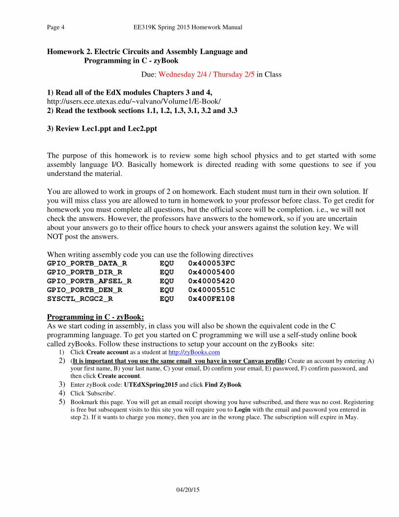
Homework 2. Electric Circuits and Assembly Language and
Programming in C - zyBook
Due: Wednesday 2/4 / Thursday 2/5 in Class
1) Read all of the EdX modules Chapters 3 and 4,
http://users.ece.utexas.edu/~valvano/Volume1/E-Book/
2) Read the textbook sections 1.1, 1.2, 1.3, 3.1, 3.2 and 3.3
3) Review Lec1.ppt and Lec2.ppt
The purpose of this homework is to review some high school physics and to get started with some
assembly language I/O. Basically homework is directed reading with some questions to see if you
understand the material.
You are allowed to work in groups of 2 on homework. Each student must turn in their own solution. If
you will miss class you are allowed to turn in homework to your professor before class. To get credit for
homework you must complete all questions, but the official score will be completion. i.e., we will not
check the answers. However, the professors have answers to the homework, so if you are uncertain
about your answers go to their office hours to check your answers against the solution key. We will
NOT post the answers.
When writing assembly code you can use the following directives GPIO_PORTB_DATA_R EQU 0x400053FC
GPIO_PORTB_DIR_R EQU 0x40005400
GPIO_PORTB_AFSEL_R EQU 0x40005420
GPIO_PORTB_DEN_R EQU 0x4000551C
SYSCTL_RCGC2_R EQU 0x400FE108
Programming in C - zyBook:
As we start coding in assembly, in class you will also be shown the equivalent code in the C
programming language. To get you started on C programming we will use a self-study online book
called zyBooks. Follow these instructions to setup your account on the zyBooks site: 1) Click Create account as a student at http://zyBooks.com
2) (It is important that you use the same email you have in your Canvas profile) Create an account by entering A)
your first name, B) your last name, C) your email, D) confirm your email, E) password, F) confirm password, and
then click Create account. 3) Enter zyBook code: UTEdXSpring2015 and click Find ZyBook 4) Click 'Subscribe'. 5) Bookmark this page. You will get an email receipt showing you have subscribed, and there was no cost. Registering
is free but subsequent visits to this site you will require you to Login with the email and password you entered in
step 2). If it wants to charge you money, then you are in the wrong place. The subscription will expire in May.

Ramesh Yerraballi EE319K Spring 2015 Homework Manual Page 5
[email protected] 4/20/2015
Problem 2.1 . What is Ohm’s Law?
Problem 2.2: Fill in this table with the equivalent resistance (all values are in ohms)
R1 R2 R1 in series with
R2
R1 in parallel with R2
1000
2000
2000
10000
1000
4000
2000
1600
Problem 2.3. What is the range of voltages that represent logic low?
Problem 2.4. What is the range of voltages that represent logic high?
Problem 2.5. Write assembly code to set the Port B direction register so PB7-PB4 are output and PB3-0
are inputs.
Problem 2.6. Assume Port B is initialized and PB5 is an output pin. Write assembly code to set PB5
high. It will take three steps 1) read the data register; 2) perform a logical operation to set bit 5; and then
3) write the new value back to the data register. Hint: this is similar to Example 3.1.
Problem 2.7. Complete your subscription on zyBooks website and read Chapter 1 and complete
Activity 1.1.2.
Page 6 EE319K Spring 2015 Homework Manual
04/20/15
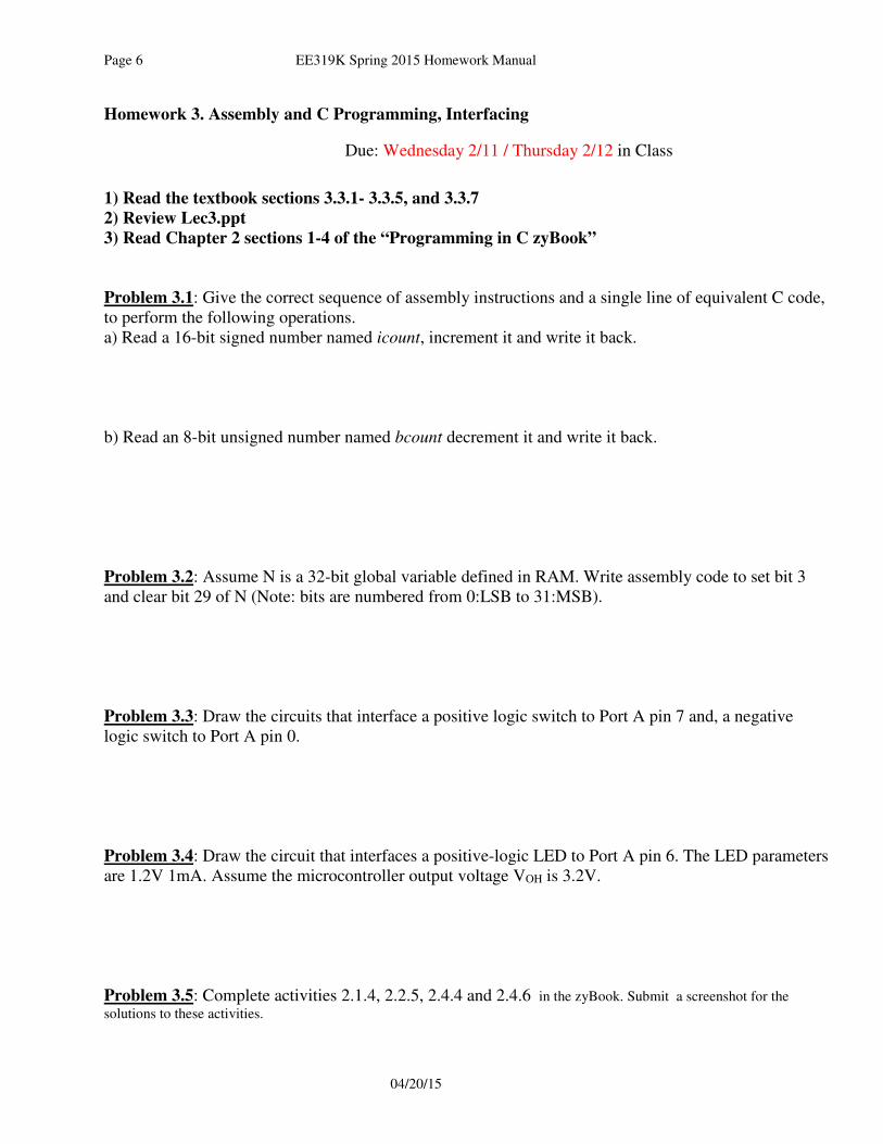
Homework 3. Assembly and C Programming, Interfacing
Due: Wednesday 2/11 / Thursday 2/12 in Class
1) Read the textbook sections 3.3.1- 3.3.5, and 3.3.7
2) Review Lec3.ppt
3) Read Chapter 2 sections 1-4 of the “Programming in C zyBook”
Problem 3.1: Give the correct sequence of assembly instructions and a single line of equivalent C code,
to perform the following operations.
a) Read a 16-bit signed number named icount, increment it and write it back.
b) Read an 8-bit unsigned number named bcount decrement it and write it back.
Problem 3.2: Assume N is a 32-bit global variable defined in RAM. Write assembly code to set bit 3
and clear bit 29 of N (Note: bits are numbered from 0:LSB to 31:MSB).
Problem 3.3: Draw the circuits that interface a positive logic switch to Port A pin 7 and, a negative
logic switch to Port A pin 0.
Problem 3.4: Draw the circuit that interfaces a positive-logic LED to Port A pin 6. The LED parameters
are 1.2V 1mA. Assume the microcontroller output voltage VOH is 3.2V.
Problem 3.5: Complete activities 2.1.4, 2.2.5, 2.4.4 and 2.4.6 in the zyBook. Submit a screenshot for the
solutions to these activities.
Ramesh Yerraballi EE319K Spring 2015 Homework Manual Page 7
[email protected] 4/20/2015
Homework 4: Conditional statements in C
Due: Wednesday 2/18 / Thursday 2/19 in Class
1) Read EdX Chapter 5: sections 5.1, 5.2 and 5.3
http://users.ece.utexas.edu/~valvano/Volume1/E-Book/
2) Read Chapter 3 on zyBook and complete all activities in the chapter. Submit a screenshot for
the solutions to the two Challenge homework activities 3.1.1. and3.1.2.

Page 8 EE319K Spring 2015 Homework Manual
04/20/15
Homework 5 – Practice Exam
Due: Wednesday 2/25 / Thursday 2/26 in Class
UT EID:
Printed Name:
Last, First
Your signature is your promise that you have not cheated and will not cheat on this exam, nor will you help others to cheat on
this exam:
Signature:
Instructions:
• Closed book and closed notes. No books, no papers, no data sheets (other than the last two pages of this Exam)
• No devices other than pencil, pen, eraser (no calculators, no electronic devices), please turn cell phones off.
• Please be sure that your answers to all questions (and all supporting work that is required) are contained in the space
(boxes) provided. Anything outside the boxes/blanks will be ignored in grading. You may use the back of the sheets
for scratch work.
• You have 75 minutes, so allocate your time accordingly.
• For all questions, unless otherwise stated, find the most efficient (time, resources) solution.
• Unless otherwise stated, make all I/O accesses friendly.
• Please read the entire exam before starting.
Problem 1 10
Problem 2 6
Problem 3 4
Problem 4 10
Problem 5 20
Problem 6 10
Problem 7 10
Problem 8 15
Problem 9 15
Total 100

Ramesh Yerraballi EE319K Spring 2015 Homework Manual Page 9
[email protected] 4/20/2015
(10) Question 1. State the term, symbol, or expression that is best described by each definition.
Part a) A property of memory that describes the fact that when power is
removed and subsequently restored, the contents of the memory is lost.
Part b) A debugging instrument or tool that measures voltage versus time for
multiple digital signals.
Part c) A drawing that describes how information is passed from one module to
another in a system. An arrow from circle A to circle B means information is
passed from software module A to software module B.
Part d) A collection of wires in a computer that allows data to travel from one
module to another within the computer.
Part e) A processor in which the operands to ALU instructions are never a
memory location uses what type of generic architecture? (Hint: the answer to
this question is not ARM, THUMB, or Cortex-M, but rather the general
architecture type.)
Part f) The electrical property that specifies the number of electrons per second
that are traveling down a wire.
Part g) This C operator will perform the exclusive or of two numbers in a bit-
wise fashion.
Part h) A C program calls an assembly subroutine. When the assembly
subroutine returns, where can the return value be found? (Hint: AAPCS)
Part i) This declaration is used to create a variable in C that can take on the
values from -20 to +200. Pick the most efficient format.
Part j) A debugging feature that causes execution to halt, and control returns to
the debugger when your software executes an instruction at a specific location in
your code.
Page 10 EE319K Spring 2015 Homework Manual
04/20/15
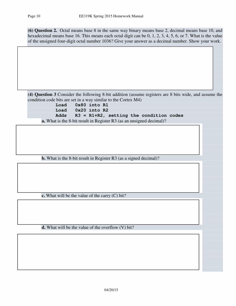
(6) Question 2. Octal means base 8 in the same way binary means base 2, decimal means base 10, and
hexadecimal means base 16. This means each octal digit can be 0, 1, 2, 3, 4, 5, 6, or 7. What is the value
of the unsigned four-digit octal number 1036? Give your answer as a decimal number. Show your work.
(4) Question 3 Consider the following 8-bit addition (assume registers are 8 bits wide, and assume the
condition code bits are set in a way similar to the Cortex M4) Load 0x80 into R1
Load 0x20 into R2
Adds R3 = R1+R2, setting the condition codes
a. What is the 8-bit result in Register R3 (as an unsigned decimal)?
b. What is the 8-bit result in Register R3 (as a signed decimal)?
c. What will be the value of the carry (C) bit?
d. What will be the value of the overflow (V) bit?
139
-117-

Ramesh Yerraballi EE319K Spring 2015 Homework Manual Page 11
[email protected] 4/20/2015
(10) Question 4. Complete the assembly subroutine that initializes Port D, making PD4 an output, and
making PD3, PD2, PD1, PD0 inputs. This subroutine is called once at the start of execution of the
system. All accesses to I/O registers must be friendly. Your subroutine will set the clock, direction,
and enable registers (in this question do not worry about AFSEL, PUR, PDR, AMSEL, or PCTL). You
must fill in the instruction or instructions for the following five boxes. Boxes may contain 0, 1, or 2
instructions. Do not assume DIR, DEN or DATA registers have been cleared by the reset operation.
Comments are not needed.
GPIO_PORTD_DATA_R EQU 0x400073FC
GPIO_PORTD_DIR_R EQU 0x40007400
GPIO_PORTD_DEN_R EQU 0x4000751C
SYSCTL_RCGCGPIO_R EQU 0x400FE608
PortD_Init
LDR R1, =SYSCTL_RCGCGPIO_R
LDR R0, [R1]
STR R0, [R1]
LDR R1, =GPIO_PORTD_DIR_R
LDR R0, [R1]
STR R0, [R1]
LDR R1, =GPIO_PORTD_DEN_R
LDR R0, [R1]
STR R0, [R1]

Page 12 EE319K Spring 2015 Homework Manual
04/20/15
(20) Question 5. The inputs are on Port D pins 3,2,1,0. The output is PD4. Design a detector that reads
a 4-bit number on PD3 – PD0 and activates a positive-logic detection light on PD4. First, read the 4-bit
input and count the number of input pins, PD3 – PD0, that are high. If the count is odd, set PD4 high; if
the count is even, clear PD4 low. For example, if PD3 – PD0 is 1011 then there are an odd number of
pins that are high, the pattern is detected, and the PD4 should be set high. When such a pattern is
detected turn ON the light otherwise turn it off. You will design pieces of the solution in two parts. You
may assume the subroutine in Question 4 has been called making PD4 an output and making PD3 –
PD0 inputs.
Part a) Write an assembly subroutine called Detect that takes a 4-bit input in a register (the remaining
bits are zero). Returns a 1 if pattern is detected, 0 otherwise. Detect must be AAPCS compliant.
Part b) Complete the caller code loop in assembly that repeatedly reads the 4-bit number, calls Detect
and appropriately manipulates the light. Execute these steps over and over.

Ramesh Yerraballi EE319K Spring 2015 Homework Manual Page 13
[email protected] 4/20/2015
(10) Question 6. You are to interface an external LED on Port D pin 4 that operates using positive
logic. You have an LED whose desired brightness requires an operating point of (Vd , Id) = (1.5V,
15mA). Given the TM4C microcontroller output low VOL ranges between (0V,0.5V) and output high
VOH ranges between (2.4V,3.3V). The 7406 driver’s VOL is 0.5V. Show the calculation used to find the
resistor value needed and draw the circuit below by connecting the needed elements:
R
PD4
Microcontroller
7406
+3.3V+5V
0V
(10) Question 7. You are to interface an external Switch on Port D pin 2 that operates using negative
logic by using the needed elements in the following figure.
(8) Part a) Given the TM4C microcontroller limits the current flow into it to 2 µA calculate the voltage
at Port D pin 2 when the switch is open. Choose a value for R and specify its value.
R
PD2
Microcontroller
7406
+3.3V+5V
0V
(2) Part b) If you were using an internal resistor (instead of an external one) what extra line(s) would you have to
add to the initialization for port D. (C or Assembly is okay)
R =
VPD2 =
Page 14 EE319K Spring 2015 Homework Manual
04/20/15
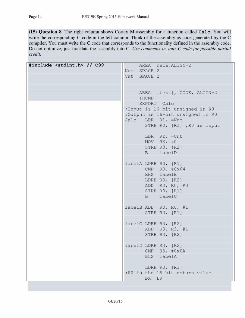
(15) Question 8. The right column shows Cortex M assembly for a function called Calc. You will
write the corresponding C code in the left column. Think of the assembly as code generated by the C
compiler. You must write the C code that corresponds to the functionality defined in the assembly code.
Do not optimize, just translate the assembly into C. Use comments in your C code for possible partial
credit.
#include <stdint.h> // C99
AREA Data,ALIGN=2
Num SPACE 2
Cnt SPACE 2
AREA |.text|, CODE, ALIGN=2
THUMB
EXPORT Calc
;Input is 16-bit unsigned in R0
;Output is 16-bit unsigned in R0
Calc LDR R1, =Num
STRH R0, [R1] ;R0 is input
LDR R2, =Cnt
MOV R3, #0
STRH R3, [R2]
B labelD
labelA LDRH R0, [R1]
CMP R0, #0x64
BHS labelB
LDRH R3, [R2]
ADD R0, R0, R3
STRH R0, [R1]
B labelC
labelB ADD R0, R0, #1
STRH R0, [R1]
labelC LDRH R3, [R2]
ADD R3, R3, #1
STRH R3, [R2]
labelD LDRH R3, [R2]
CMP R3, #0x0A
BLS labelA
LDRH R0, [R1]
;R0 is the 16-bit return value
BX LR

Ramesh Yerraballi EE319K Spring 2015 Homework Manual Page 15
[email protected] 4/20/2015
(15) Question 9. Consider the following assembly code. Execution begins at line 127 in main, and the
initial SP equals 0x20000100. 111: ;R0 dividend
112: ;R1 divisor
113: ;R0 is returned with remainder
114: 0x000002F8 B500 mod PUSH {LR}
115: 0x000002FA FBB0F3F1 UDIV R3, R0, R1 ;<-stop execution here
116: 0x000002FE FB03F301 MUL R3, R3, R1
117: 0x00000302 EBA00003 SUB R0, R0, R3
118: 0x00000306 BD00 POP {PC}
119: 0x00000308 B510 fun PUSH {R4,LR}
120: 0x0000030A F04F040A MOV R4, #10
121: 0x0000030E F04F0010 loop MOV R0, #16
122: 0x00000312 4621 MOV R1, R4
123: 0x00000314 F7FFFFF0 BL mod ;<-what addressing mode??
124: 0x00000318 3C01 SUBS R4, #1
125: 0x0000031A D1F8 BNE loop
126: 0x0000031C BD10 POP {R4,PC}
127: 0x0000031E F04F0405 main MOV R4, #5 ;<- begin execution here
128: 0x00000322 F7FFFFF1 BL fun
129: 0x00000326 E7FE done B done
Part a) What is the SP when execution reaches line 115 for the first time?
Part b) What values are stored on the stack as it executes from line 127 to line 115? Show each value as
a 32-bit hexadecimal number into the appropriate place on the stack picture. The addresses and machine
code are included for each line.
Part c) What is the addressing mode of the instruction at line 123?
Part d) What does B500 at line 114 represent?
0x200000F0
0x200000F4
0x200000F8
0x200000FC
0x20000100
0x20000104
0x20000108
0x2000010C
0x20000110
Initial SP
Page 16 EE319K Spring 2015 Homework Manual
04/20/15
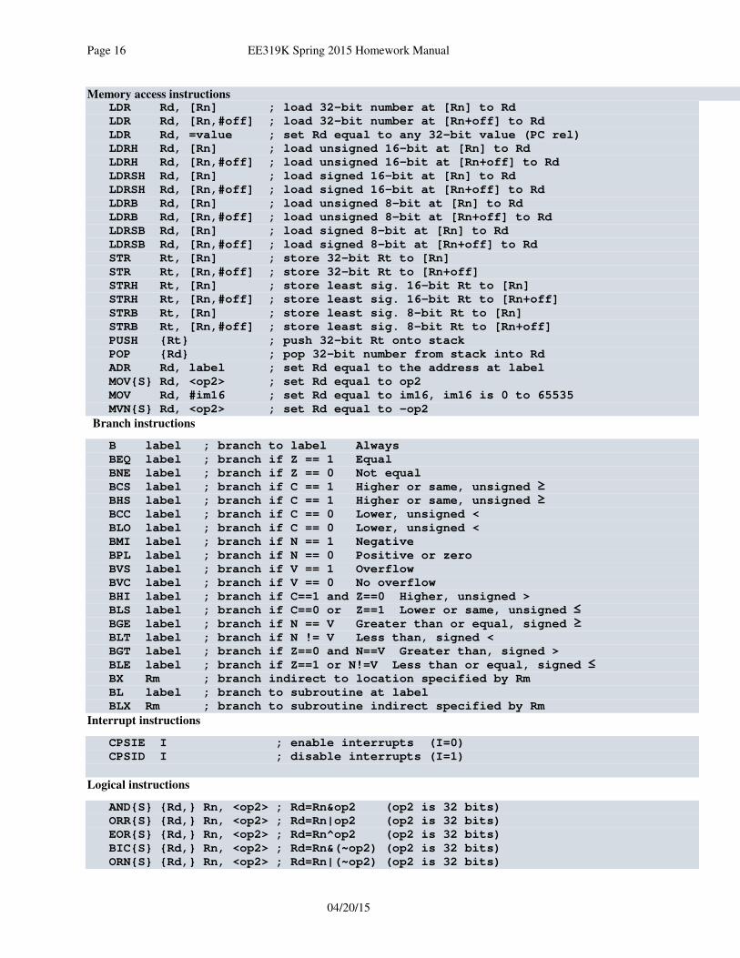
Memory access instructions LDR Rd, [Rn] ; load 32-bit number at [Rn] to Rd
LDR Rd, [Rn,#off] ; load 32-bit number at [Rn+off] to Rd
LDR Rd, =value ; set Rd equal to any 32-bit value (PC rel)
LDRH Rd, [Rn] ; load unsigned 16-bit at [Rn] to Rd
LDRH Rd, [Rn,#off] ; load unsigned 16-bit at [Rn+off] to Rd
LDRSH Rd, [Rn] ; load signed 16-bit at [Rn] to Rd
LDRSH Rd, [Rn,#off] ; load signed 16-bit at [Rn+off] to Rd
LDRB Rd, [Rn] ; load unsigned 8-bit at [Rn] to Rd
LDRB Rd, [Rn,#off] ; load unsigned 8-bit at [Rn+off] to Rd
LDRSB Rd, [Rn] ; load signed 8-bit at [Rn] to Rd
LDRSB Rd, [Rn,#off] ; load signed 8-bit at [Rn+off] to Rd
STR Rt, [Rn] ; store 32-bit Rt to [Rn]
STR Rt, [Rn,#off] ; store 32-bit Rt to [Rn+off]
STRH Rt, [Rn] ; store least sig. 16-bit Rt to [Rn]
STRH Rt, [Rn,#off] ; store least sig. 16-bit Rt to [Rn+off]
STRB Rt, [Rn] ; store least sig. 8-bit Rt to [Rn]
STRB Rt, [Rn,#off] ; store least sig. 8-bit Rt to [Rn+off]
PUSH {Rt} ; push 32-bit Rt onto stack
POP {Rd} ; pop 32-bit number from stack into Rd
ADR Rd, label ; set Rd equal to the address at label
MOV{S} Rd, <op2> ; set Rd equal to op2
MOV Rd, #im16 ; set Rd equal to im16, im16 is 0 to 65535
MVN{S} Rd, <op2> ; set Rd equal to -op2
Branch instructions
B label ; branch to label Always
BEQ label ; branch if Z == 1 Equal
BNE label ; branch if Z == 0 Not equal
BCS label ; branch if C == 1 Higher or same, unsigned ≥
BHS label ; branch if C == 1 Higher or same, unsigned ≥
BCC label ; branch if C == 0 Lower, unsigned <
BLO label ; branch if C == 0 Lower, unsigned <
BMI label ; branch if N == 1 Negative
BPL label ; branch if N == 0 Positive or zero
BVS label ; branch if V == 1 Overflow
BVC label ; branch if V == 0 No overflow
BHI label ; branch if C==1 and Z==0 Higher, unsigned >
BLS label ; branch if C==0 or Z==1 Lower or same, unsigned ≤
BGE label ; branch if N == V Greater than or equal, signed ≥
BLT label ; branch if N != V Less than, signed <
BGT label ; branch if Z==0 and N==V Greater than, signed >
BLE label ; branch if Z==1 or N!=V Less than or equal, signed ≤
BX Rm ; branch indirect to location specified by Rm
BL label ; branch to subroutine at label
BLX Rm ; branch to subroutine indirect specified by Rm
Interrupt instructions
CPSIE I ; enable interrupts (I=0)
CPSID I ; disable interrupts (I=1)
Logical instructions
AND{S} {Rd,} Rn, <op2> ; Rd=Rn&op2 (op2 is 32 bits)
ORR{S} {Rd,} Rn, <op2> ; Rd=Rn|op2 (op2 is 32 bits)
EOR{S} {Rd,} Rn, <op2> ; Rd=Rn^op2 (op2 is 32 bits)
BIC{S} {Rd,} Rn, <op2> ; Rd=Rn&(~op2) (op2 is 32 bits)
ORN{S} {Rd,} Rn, <op2> ; Rd=Rn|(~op2) (op2 is 32 bits)

Ramesh Yerraballi EE319K Spring 2015 Homework Manual Page 17
[email protected] 4/20/2015
LSR{S} Rd, Rm, Rs ; logical shift right Rd=Rm>>Rs (unsigned)
LSR{S} Rd, Rm, #n ; logical shift right Rd=Rm>>n (unsigned)
ASR{S} Rd, Rm, Rs ; arithmetic shift right Rd=Rm>>Rs (signed)
ASR{S} Rd, Rm, #n ; arithmetic shift right Rd=Rm>>n (signed)
LSL{S} Rd, Rm, Rs ; shift left Rd=Rm<<Rs (signed, unsigned)
LSL{S} Rd, Rm, #n ; shift left Rd=Rm<<n (signed, unsigned)
Arithmetic instructions
ADD{S} {Rd,} Rn, <op2> ; Rd = Rn + op2
ADD{S} {Rd,} Rn, #im12 ; Rd = Rn + im12, im12 is 0 to 4095
SUB{S} {Rd,} Rn, <op2> ; Rd = Rn - op2
SUB{S} {Rd,} Rn, #im12 ; Rd = Rn - im12, im12 is 0 to 4095
RSB{S} {Rd,} Rn, <op2> ; Rd = op2 - Rn
RSB{S} {Rd,} Rn, #im12 ; Rd = im12 – Rn
CMP Rn, <op2> ; Rn – op2 sets the NZVC bits
CMN Rn, <op2> ; Rn - (-op2) sets the NZVC bits
MUL{S} {Rd,} Rn, Rm ; Rd = Rn * Rm signed or unsigned
MLA Rd, Rn, Rm, Ra ; Rd = Ra + Rn*Rm signed or unsigned
MLS Rd, Rn, Rm, Ra ; Rd = Ra - Rn*Rm signed or unsigned
UDIV {Rd,} Rn, Rm ; Rd = Rn/Rm unsigned
SDIV {Rd,} Rn, Rm ; Rd = Rn/Rm signed
Notes Ra Rd Rm Rn Rt represent 32-bit registers
value any 32-bit value: signed, unsigned, or address
{S} if S is present, instruction will set condition codes
#im12 any value from 0 to 4095
#im16 any value from 0 to 65535
{Rd,} if Rd is present Rd is destination, otherwise Rn
#n any value from 0 to 31
#off any value from -255 to 4095
label any address within the ROM of the microcontroller
op2 the value generated by <op2>
Examples of flexible operand <op2> creating the 32-bit number. E.g., Rd = Rn+op2
ADD Rd, Rn, Rm ; op2 = Rm
ADD Rd, Rn, Rm, LSL #n ; op2 = Rm<<n Rm is signed, unsigned
ADD Rd, Rn, Rm, LSR #n ; op2 = Rm>>n Rm is unsigned
ADD Rd, Rn, Rm, ASR #n ; op2 = Rm>>n Rm is signed
ADD Rd, Rn, #constant ; op2 = constant, where X and Y are hexadecimal digits:
• produced by shifting an 8-bit unsigned value left by any number of bits
• in the form 0x00XY00XY
• in the form 0xXY00XY00
• in the form 0xXYXYXYXY
R0R1R2R3R4R5R6R7R8R9R10R11R12
R13 (MSP)R14 (LR)R15 (PC)
Stack pointerLink register
Program counter
Generalpurpose
registers
Condition code bits
N negative
Z zero
V signed overflow
C carry or
unsigned overflow
256k FlashROM
32k RAM
I/O ports
Internal I/OPPB
0x0000.0000
0x0003.FFFF
0x2000.0000
0x2000.7FFF
0x4000.0000
0x400F.FFFF
0xE000.0000
0xE004.1FFF

Page 18 EE319K Spring 2015 Homework Manual
04/20/15
Ramesh Yerraballi EE319K Spring 2015 Homework Manual Page 19
[email protected] 4/20/2015
Homework 6. Loops and Arrays in C
Due: Wednesday 3/11 / Thursday 3/12 in Class
The purpose of this homework is to learn loops and arrays in C programming.
1) Read EdX Chapters 7 and 9: all sections; watch the videos
http://users.ece.utexas.edu/~valvano/Volume1/E-Book/
2) Log into Zybooks and read Chapters 4 and 5
The exercises are practice programs to write, but not turn in. The assignment is a program you will
write, debug and turn in. Create a one page print out of a screen shot showing some of the program code
and run time output. In this homework we will look at basics of arrays and revisit the for-loop as a
natural fit for traversing an array.
Exercise 6.1: Do all activities in chapters 4 of the zyBook.
Assignment 6.1: Submit one sheet each (screenshots) of your code for Homework challenges 4.2.2,
4.4.2 and 4.5.2 from the zyBook.
Exercise 6.2: Do all activities in chapters 5 (except 5.5) of the zyBook.
Assignment 6.2: Submit one sheet each (screenshots) of your code for Homework challenges 5.2.2,
5.4.1 and 5.4.2 from the zyBook.
Page 20 EE319K Spring 2015 Homework Manual
04/20/15
Homework 7. Subroutines in C, Parameter-passing and Pointers
Due: Wednesday 3/25 / Thursday 3/26 in Class
The purpose of this homework is to learn how to write subroutines in C and to pass parameters to and
results from a subroutine. You will also learn the use of pointers.
Exercise 7.1: Read Chapter 6 sections 1 through 5 from the zyBook.
To demonstrate you completed this assignment make a one page printout of the most interesting part of
this reading and place your name at the top. As usual, show this to the TA at the start of class.

Ramesh Yerraballi EE319K Spring 2015 Homework Manual Page 21
[email protected] 4/20/2015
Homework 8. Practice Exam 2 (1/2)
Due: Wednesday 4/1 / Thursday 4/2 in Class
Download the following old exam:
http://users.ece.utexas.edu/~valvano/Volume1/Exam2X-S14.zip
Assignment 8.1: Do the example Exam2 called Number in String from Spring 2014:
1) Unzip Exam2X-S14.zip
2) Print out pdf (read just the first page)
3) Launch the uvproj that starts Keil uVision
4) Build the object code Target->Rebuild all target files
Start a stopwatch and measure how many points you achieve in 35 minutes. Measure how many minutes
it takes you to get to 100 points. Print one page of your solution and write the two measurements (points
in 35 minutes, and time to 100 points for the exams)
See http://users.ece.utexas.edu/~valvano/Volume1/Exam2thoughts.pdf for more information on the
exam.
There are four other practice exams in C at http://users.ece.utexas.edu/~valvano/Volume1/
Page 22 EE319K Spring 2015 Homework Manual
04/20/15
Homework 9. Practice Exam 2 (2/2)
Assignment 9.1: Do the example Exam2 called Merge:
1) Unzip http://users.ece.utexas.edu/~valvano/Volume1/Exam2_Merge.zip
2) Print out pdf (read just the first page)
3) Launch the uvproj that starts Keil uVision
4) Build the object code Target->Rebuild all target files
Start a stopwatch and measure how many points you achieve in 60 minutes. Measure how many minutes
it takes you to get to 100 points. Print one page of your solution and write the two measurements (points
in 60 minutes, and time to 100 points for the exams)
Due: Wednesday 4/8 / Thursday 4/9 in Class
Ramesh Yerraballi EE319K Spring 2015 Homework Manual Page 23
[email protected] 4/20/2015
Homework 10. Structs in C
Due: Wednesday 4/22 / Thursday 4/23 in Class
Exercise 10: Read all of Chapters 7 and 8 in the zyBook
Assignment 10.1:
Structs: Complete Challenge homework activities 7.1.1 and 7.1.2
Structs and arrays: Modify the TV watch program(Try 7.2.1)
Assignment 10.2: Complete Challenge homework activities 8.1.1 and 8.1.2


