Download - QuickLoad Installation Guide - Air Weigh
1PN 901-0144-002 R1
Air-Weigh Customer Support: 888-459-3247
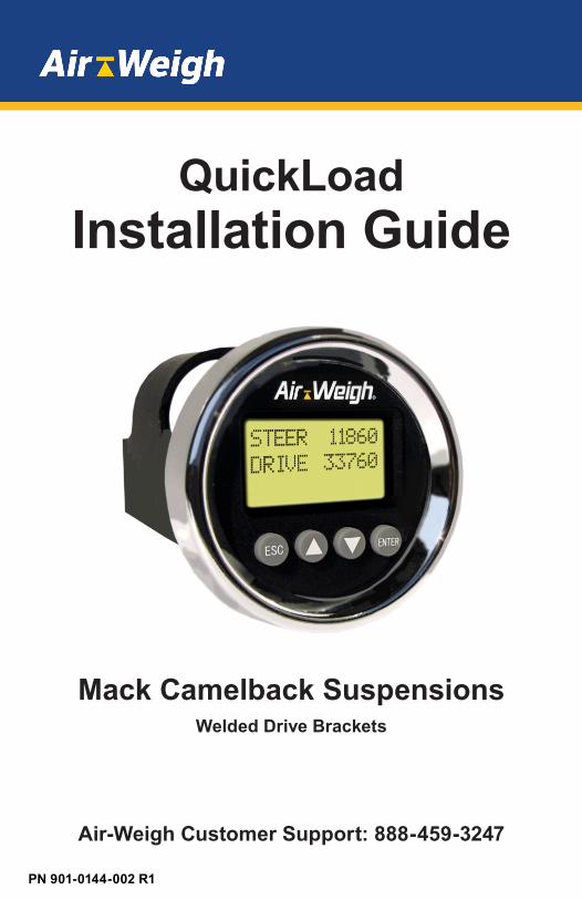
QuickLoadInstallation Guide
Mack Camelback SuspensionsWelded Drive Brackets

2
Table of Contents
Scale Overview.................................................................................1 Overview: Sensor Installation......................................................1Tools Required.................................................................................2Installing the Sensor Bracket on the Camelback Suspension...3 Preparing the Camelback Suspension......................................3 Welding the Bracket......................................................................4 Adding a Protective Spray Paint Coating..................................5Installing the Display and Cables..................................................6 Routing the Sensor Extension Cable.........................................6 Preparing the Cab Display for Installation.................................7 Installing the Cab Display.............................................................7Deflection Sensor Installation........................................................8 Securing Cables and Reassembling the Dash........................9 Setting the Sensor A/D Values.................................................10 Assembling the Electrical Connector.......................................10 Adjusting the A/D Reading.........................................................11 Final Sensor Torque....................................................................12Cover Installation...........................................................................13Sensor Configuration Chart.........................................................15Notes...............................................................................................22 Limited Warranty............................................................................24Procedure for Warranty Claims...................................................25

1
Scale Overview
The Air-Weigh QuickLoad Scale for vocational vehicles with the Mack Camelback suspension includes a dashboard-mounted QuickLoad display, power harness, a deflection sensor with mounting hardware for the Camelback suspension, and sensor cables.This Installation Guide provides all the instructions needed to install the deflection sensor on the Camelback suspension.Follow the installing procedures in this guide exactly for the most accurate weighing.The User Guide, included with the scale kit, provides the complete scale calibration and operation procedures.
Overview: Sensor Installation The following overview steps are to be applied to the Camelback Suspension Sensor Installation:
• Mark the center of the trunnion tube. • Mount bracket assembly on the trunnion tube. • Connect the cables • Route the extension cable through the firewall and connect
it to the QuickLoad Scale Sensor Port A.• Mount the sensor to the bracket.• Check for sensor readings in range.• Mount the cover over the sensor and brackets.
2
Tools RequiredThe list below contains the tools (customer supplied) to properly install the deflection sensor on the Mack Camelback Suspension.
• Sander/grinder • 40-grit medium sandpaper• Chalk or permanent marker• 22mm combination wrench• Torque wrench, 20 – 120 ft-lb • 22mm socket and 3/8-inch socket handle• Enamel spray paint• Tape measure• C clamps• ARC or MIG welder• 5/16 socket or flathead screwdriver
Note: Heavy calibration must be done using maximum vehicle loads. See QuickLoad Calibrations and Operations manual, for additional information on calibration.
Cables to the sensor, and any other Air-Weigh wiring, must be separated by a minimum of 12 inches, or properly shielded, from exhaust piping.
Do not move vehicle until the alignment tool is removed.
Do not calibrate sensor following installation until the sensors have had a break-in period. Break-in periods are dependent on a number of factors, including but not limited to: work environment the scale is subject to; road conditions; vehicle conditions; normal wear and tear. This can cause the break-in period to vary from 100 miles to 800 miles.

3
Installing the Sensor Bracket on theCamelback Suspension
Preparing the Camelback SuspensionLocate and mark the top center of the trunnion tube.
Sanding the Trunnion Tube
Marking Center of Trunnion Tube
2. Using chalk or permanent marker, mark the top of the trunnion tube 3-3/8 in. (85.725mm) on both sides of the center mark. The overall measurement is 6-3/4 in. (171.45 mm).
3. Using a grinder or 40-grit medium sandpaper, sand the marked off area until it is free of paint and other residues.
4. Clean the sanded area. 5. Re-mark the center of the trunnion tube.

4
Welding the Bracket
1. Place the mounting bracket assembly on the top center of the trunnion tube. Mark the center on the alignment tool and ensure it lines up with the center mark on the trunnion tube.
2. Use C clamps to hold the bracket in place. Make sure you leave the alignment tool in the bracket assembly while welding.
Placing the Brackets on the Trunnion Tube
3. Tack weld all 8 corners of the base of the bracket.4. Fillet weld a full bead on the edges of each bracket piece.5. Allow the weld and the bracket to completely cool.
Alignment Tool
5
Alignment Tool
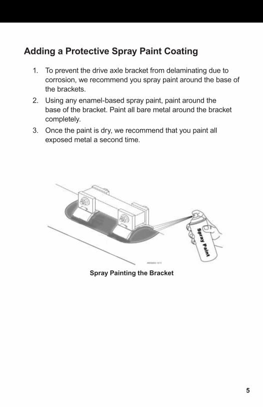
Adding a Protective Spray Paint Coating
1. To prevent the drive axle bracket from delaminating due to corrosion, we recommend you spray paint around the base of the brackets.
2. Using any enamel-based spray paint, paint around the base of the bracket. Paint all bare metal around the bracket completely.
3. Once the paint is dry, we recommend that you paint all exposed metal a second time.
Spray Painting the Bracket

6
Installing the Display and Cables
Routing the Sensor Extension Cable
1. Starting from where you mounted the bracket, route the drive axle extension cable along the axle and the frame, and then through the cab firewall to where you will install the in-cab display on the dash. If possible, route along an existing wire harness. Be careful to avoid routing along pieces of the frame that may move or cause wiring to rub.
2. The drive axle sensor extension cable will be connected to Sensor Port A on the back of the QuickLoad display once the display is installed.
3. Coil and secure the drive axle extension cable approximately every foot along the frame of the truck using zip ties. Leave the ties loosely attached, as you will tighten them later in the install process.
Note: Keep all cables a minimum of 12” from exhaust piping or properly shield cables.
Drive Axle Connections

7
Preparing the Cab Display for Installation The Optional Universal Mounting Pod can be used for installations where there is no space in the dash to mount the scale display.
1. Select a location for the display (1) on the dash panel (5) with at least 3” of clearance behind the dash panel (5) for the unit and its connections. A higher dash position provides better visibility.
2. Using a hole saw, cut a 2-1/8” hole (2) in the dash where you will mount the display.
3. Remove the hex nuts (4) from the studs (6) on the back of the display (1) to release the mounting bracket (3).
Installing the Cab Display1. Position the display (1) in the hole so that it appears level on
the dash. 2. Reinstall the mounting bracket (3) on the back of the display
(1) and secure with two nuts (4) on the display studs (6). Tighten the nuts (4) and secure the display (1) to the dash using 6 in-lbs. of torque. Do not over- tighten the mounting bracket nuts (4).
3. Connect the drive axle extension cable to the display in the dash to Port A.
Display Preparation and Installation

8
Deflection Sensor Installation1. Insert the deflection sensor into the brackets with its cable
extending toward the side of the vehicle where you routed the sensor extension cable to the firewall. The engraved lettering on the sensor should face up.
2. Align the deflection sensor with the bracket holes.
Inserting the Sensor
3. Slide the bolt through the bracket holes so that the bolthead is secured in the manufactured bolthead holder.
Inserting Bolt and Washers into Sensor and Bracket
9
Securing Cables and Reassembling the Dash
1. Coil and secure any excess wire using zip ties.2. Tighten all zip ties and trim.3. Reassemble the dash assembly after the sensor has been
installed and sensor cables are connected. Ensure all connections are tight.

10
Setting the A/D values
At this point, you have installed all of the QuickLoad system components. You will next adjust the deflection sensor to read weight correctly by setting its A/D values. A/D refers to the analog-to-digital conversion of the sensor reading. This step will require the use of either the QuickLoad Scale or the Deflection Sensor Test box (P/N 1001). If using the QuickLoad Scale, the scale must be installed and powered, and the Deflection Sensor Extension Cable must be installed.
Assembling the Electrical Connector1. To assemble the connectors, insert the deflection sensor
connector plug into the sensor extension cable connector OR connect to the deflection sensor test box (P/N 1001). Ensure the locking tabs on the connector plug engage completely.
Assembling the Electrical Connector
Note: When tightening the bolts, ALWAYS torque the nut, NOT the bolt head. The bolt head should be in the bolt head holder, which is built into the bracket.
11
2. Tighten both nuts and use a torque wrench to torque to 60 ft-lbs.
3. Verify the A/D reading using the display in the cab (start the ignition to power on the display), or the deflection sensor test box. If the reading is within range (750-1250), continue to instructions for the Final Sensor Torque. If the reading is not within range, follow the instructions to adjust the A/D readings below.
Adjusting the A/D ReadingIf the A/D reading is above 1250, follow these instructions:
1. Loosen the nuts on both ends of the sensor2. At the plastic nut where the cable enters the sensor,
exert DOWNWARD pressure with your fingers until the A/D reading is between 750 and 1250. Continue to apply pressure to maintain the desired A/D reading during the torque procedures in step 3.
3. Tighten the nut on the cable end of the sensor and torque to 60 ft/lbs. Continue to apply pressure with your finger to the plastic nut during torquing in order to maintain the desired A/D reading. If the A/D readings are still within the 750 to 1250 range after the nuts on both sides of the sensor have been torque to 60 ft/lbs., continue to instructions for the Final Sensor Torque.

12
If the A/D reading is below 750, or there is no A/D reading at all, follow the steps below:
1. Loosen the nuts on both ends of the sensor2. At the plastic nut where the cable enters the sensor, exert
UPWARD pressure with your fingers until the A/D reading is between 750 and 1250. Continue to apply pressure to maintain the desired A/D reading during the torque procedures in step 3.
3. Tighten the nut on the cable end of the sensor and torqued to 60 ft/lbs. Continue to apply pressure with your finger to the plastic nut during torquing in order to maintain the desired A/D reading. If the A/D readings are still within the 750 to 1250 range after the nuts on both sides of the sensor have been torqued to 60 ft/lbs., continue to instructions for the Final Sensor Torque.
Final Sensor Torque
1. Torque both nuts to 120 ft/lbs.2. Perform a final check to A/D values using the readings from
the in-cab QuickLoad display, not from the A/D Box. If A/D readings are not within range, repeat the Adjusting the A/D reading steps.

13
Cover Installation
1. Locate the opening in the end of the cover. The opening is used for the sensor cable to go through.
Cable Opening in Cover
2. Cut a notch in the supplied grommet and place it on the sensor cable.
Notching the Grommet
14
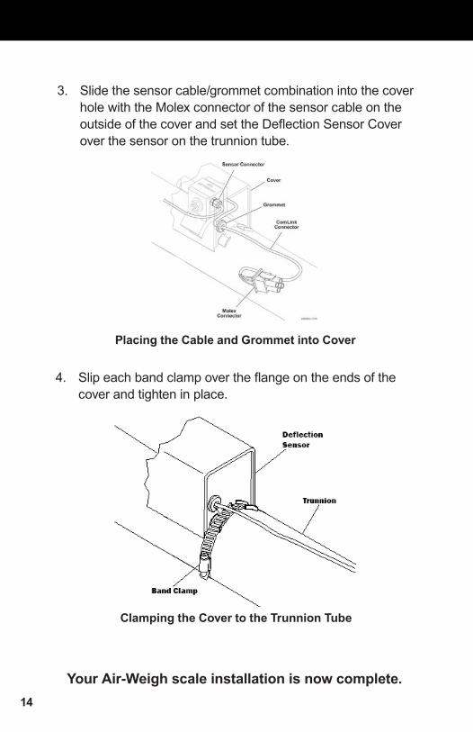
3. Slide the sensor cable/grommet combination into the cover hole with the Molex connector of the sensor cable on the outside of the cover and set the Deflection Sensor Cover over the sensor on the trunnion tube.
Placing the Cable and Grommet into Cover
4. Slip each band clamp over the flange on the ends of the cover and tighten in place.
Your Air-Weigh scale installation is now complete.
Clamping the Cover to the Trunnion Tube

15
PARTS REFERENCE1350 Display Kit, QuickLoad, with mounting hardware, power
cable, and user manual1360 Sensor Kit, QuickLoad, Air Pressure – Single Sensor,
Push–In fittings, and 3' Cable1361 Sensor Kit, QuickLoad, Air Pressure – Dual Sensors,
Push–In fittings, 3' Cable, and Y Cable1380 Alarm Kit, QuickLoad, LED and Cable1381 Alarm Relay Harness, 12V, 10A1390 Tractor/Truck Steer Axle Sensor Kit, Deflection Sensor,
mounting brackets, 15’ sensor cable, installation manual and glue
1391 Tractor/Truck Steer Axle Sensor Kit,, Deflection Sensor, mounting brackets, 15’ sensor cable, installation manual, no Glue
1392 Drive Axle Deflection Sensor Kit which includes J Brackets for vehicle with Hendrickson suspensions, 45’ sensor cable, mounting hardware and installation manual
1393 Tractor/Truck Steer Axle Sensor Kit, Deflection Sensor, mounting brackets, 25’ sensor cable, installation manual, Glue
1395 Tractor/Truck Steer Axle Sensor Kit, Deflection Sensor, mounting brackets, 25’ cable, installation manual, no Glue
1397 Mounting Brackets for vehicle with Volvo T Ride drive suspension, deflection sensor, 40’ Sensor Cable, and installation manual
1398 Mounting Brackets for vehicle with Mack Camelback drive suspension, deflection sensor and 40' cable, and Installation manual
1650 Display Kit, QuickLoad, with mounting hardware, power cable, and user manual (1350), and Sensor Kit, QuickLoad, Air Pressure – Single Sensor, Push–In fittings, and 3' Cable (1360)

16
Kit Configuration Sensor AssignmentNumberSee Kit Part Number for Model Number
Sensor Installed on this SuspensionHCV = Height Control ValveDS = Deflection Sensor
Sensor TypeAP = Air Pressure SensorsDS = Deflection SensorHY = Hydraulic SensorLC = Load Call
ComLink Sensor Cable Input Jack
5800Drive AP Sensor A
Steer Calculated N/A
5801Drive, Dual HCV’s or other dual sensors AP, AP Sensor A & B
Steer Calculated N/A
5803 Drive, Hide Steer AP Sensor A
5805Drive AP Sensor A
Steer AP Sensor B
5806Drive, Dual HCV’s or other dual sensors
AP, AP Sensor A & B
Steer AP Sensor C
5807Drive AP Sensor A
Steer DS Sensor B
5808Drive, Dual HCV’s or other dual sensors
AP, AP Sensor A & B
Steer DS Sensor C
5809 Drive, Hide Steer LC or HY Sensor A
5810 Drive, Dual DS’s, Hide Steer DS, DS Sensor A & B
5814Drive, Dual HCV’s or other dual sensors
DS, DS Sensor A & B
Steer DS Sensor C
5815
Drive, Dual HCV’s or other dual sensors
AP. AP Sensor A & B
Steer, Dual HCV’s or other dual sensors
AP, AP Sensor C & D
5816 Drive, Dual HCVs, Hide Steer AP, AP Sensor A & B
5817Drive DS Sensor A
Steer DS Sensor B
5818
Drive, Dual DS’s or other dual sensors
DS, DS Sensor A & B
Steer, Dual HVS’s or other dual sensors
AP, AP Sensor C & D
IMPORTANT SENSOR INSTALLATION INSTRUCTIONSNote: Calculated steer model numbers require the vehicle to have a 5th wheel

17
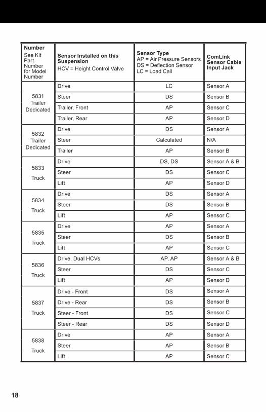
NumberSee Kit Part Number for Model Number
Sensor Installed on this SuspensionHCV = Height Control Valve
Sensor TypeAP = Air Pressure SensorsDS = Deflection SensorLC = Load Call
ComLink Sensor Cable Input Jack
5820
Drive, Load Cell LC Sensor A
<not used> N/A Sensor B
Steer, Drive DS’s DS, DS Sensor C & D
5821
Drive AP Sensor A
<not used> N/A Sensor B
Steer, Dual HVS’s or other dual sensors
AP, AP Sensor C & D
5822DRIV1/DRIV2
Drive AP Sensor A
Steer DS Sensor B
5823DRIV1/DRIV2
Drive, Dual HCV’s or other dual sensors
AP, AP Sensor A & B
Steer DS Sensor C
5824Drive, Dual DS’s DS, DS Sensor A & B
Steer AP Sensor C
5825Drive, Dual HCV’s or other dual sensors
AP, AP Sensor A & B
Steer, Dual DS’s DS, DS Sensor C & D
5826 DRIV1/DRIV2
Drive AP Sensor A
Steer AP Sensor B
5827 DRIV1/DRIV2
Drive, Dual HCV’s or other dual sensors
AP, AP Sensor A & B
Steer Calculated N/A
5828
Drive AP Sensor A
<not used> N/A Sensor B
Steer, Dual DS’s DS, DS Sensor C & D
5829Drive, Dual DS’s DS, DS Sensor A & B
Steer, Dual DS’s DS, DS Sensor C & D
5830
Truck Payload
Drive AP Sensor A
Steer HY Sensor B
18
NumberSee Kit Part Number for Model Number
Sensor Installed on this SuspensionHCV = Height Control Valve
Sensor TypeAP = Air Pressure SensorsDS = Deflection SensorLC = Load Call
ComLink Sensor Cable Input Jack
5831 Trailer
Dedicated
Drive LC Sensor A
Steer DS Sensor B
Trailer, Front AP Sensor C
Trailer, Rear AP Sensor D
5832 Trailer
Dedicated
Drive DS Sensor A
Steer Calculated N/A
Trailer AP Sensor B
5833
Truck
Drive DS, DS Sensor A & B
Steer DS Sensor C
Lift AP Sensor D
5834
Truck
Drive DS Sensor A
Steer DS Sensor B
Lift AP Sensor C
5835
Truck
Drive AP Sensor A
Steer DS Sensor B
Lift AP Sensor C
5836
Truck
Drive, Dual HCVs AP, AP Sensor A & B
Steer DS Sensor C
Lift AP Sensor D
5837
Truck
Drive - Front DS Sensor A
Drive - Rear DS Sensor B
Steer - Front DS Sensor C
Steer - Rear DS Sensor D
5838
Truck
Drive AP Sensor A
Steer AP Sensor B
Lift AP Sensor C

19
NumberSee Kit Part Number for Model Number
Sensor Installed on this SuspensionHCV = Height Control Valve
Sensor TypeAP = Air Pressure SensorsDS = Deflection SensorLC = Load Call
ComLink Sensor Cable Input Jack
5839
Truck
Drive DS Sensor A
Steer DS Sensor B
Pusher Lift AP Sensor C
Tag Lift AP Sensor D
Trailer Dedicated
5840
Drive, Hide Steer AP Sensor A
Trailer, Trailer - B - Train AP, AP Sensor B & C
Trailer Dedicated
5841
Drive AP Sensor A
Steer Calculated N/A
Trailer, Trailer - B - Train AP, AP Sensor B & C
Trailer Dedicated
5842
Drive AP Sensor A
Steer AP Sensor B
Trailer, Trailer - B - Train AP, AP Sensor C & D
Trailer Dedicated
5843
Drive AP Sensor A
Steer DS Sensor B
Trailer, Trailer - B - Train AP, AP Sensor C & D
Trailer Dedicated
5844
Drive, Dual HCVs AP, AP Sensor A & B
Trailer, Trailer - B - Train AP, AP Sensor C & D
Trailer Dedicated
5845
Drive, Dual HCVs AP, AP Sensor A & B
Steer Calculated N/A
Trailer, Trailer - B - Train AP, AP Sensor C & D
Trailer Dedicated
5846
Drive LC Sensor A
Steer DS Sensor B
Trailer, Trailer - B - Train AP, AP Sensor C & D
Trailer Dedicated
5847
Drive AP Sensor A
Steer Calculasted N/A
Trailer DS Sensor B

20
NumberSee Kit Part Number for Model Number
Sensor Installed on this SuspensionHCV = Height Control Valve
Sensor TypeAP = Air Pressure SensorsDS = Deflection SensorLC = Load Call
ComLink Sensor Cable Input Jack
Trailer Dedicated
5849
Drive DS Sensor A
Steer Calculated N/A
Trailer Dedicated
5850
Drive, Hide Steer AP Sensor A
Trailer AP Sensor B
Trailer Dedicated
5851
Drive AP Sensor A
Steer Calculated N/A
Trailer AP Sensor B
Trailer Dedicated
5852
Drive AP Sensor A
Steer AP Sensor B
Trailer AP Sensor C
Trailer Dedicated
5853
Drive AP Sensor A
Steer DS Sensor B
Trailer AP Sensor C
Trailer Dedicated
5854
Drive, Dual HCVs, Hide Steer AP, AP Sensor A & B
Trailer AP Sensor C
Trailer Dedicated
5855
Drive, Dual HCVs AP, AP Sensor A & B
Steer Calculated N/A
Trailer AP Sensor C
Trailer Dedicated
5856
Drive, Dual HCVs AP, AP Sensor A & B
Steer AP Sensor C
Trailer AP Sensor D
Trailer Dedicated
5857
Drive, Dual HCVs AP, AP Sensor A & B
Steer DS Sensor C
Trailer AP Sensor D
Trailer Dedicated
5860
Drive, Dual HCVs AP, AP Sensor A & B
Steer Calculated N/A
Trailer, Dual HCVs AP, AP Sensor C & D
Trailer Dedicated
5863
Drive LC Sensor A
Steer DS Sensor B
Trailer AP Sensor C

21
NumberSee Kit Part Number for Model Number
Sensor Installed on this SuspensionHCV = Height Control Valve
Sensor TypeAP = Air Pressure SensorsDS = Deflection SensorLC = Load Call
ComLink Sensor Cable Input Jack
Trailer Dedicated
5864
Drive AP Sensor A
Steer DS Sensor B
Pusher Lift AP Sensor C
Tag Lift AP Sensor D
5878 No FSK
Drive, Dual HCVs AP, AP Sensor A & B
Steer DS Sensor C

22
Notes

23
Notes

24
Limited WarrantyAir-Weigh warrants (the “Limited Warranty”) that the Products will be free from defects in material and workmanship under normal use and service with proper maintenance for the following time periods:
(a) for new Scale kits, the Limited Warranty period will be 3 years; (b) for new parts and accessories sold separately, the Limited Warranty period will
be 1 year; and (c) for repaired or refurbished items, including repaired or refurbished Scale kits
and repaired or refurbished parts and accessories sold separately, the Limited Warranty period will be 90 days.
If any Product is determined to not conform to this Limited Warranty during its applicable Limited Warranty period, Air-Weigh will, at its exclusive option, either repair or replace the Product.
Limitations of Limited Warranty. Air-Weigh will have no obligation under the Limited Warranty with respect to any product if (a) Buyer fails to notify Air-Weigh in writing during the warranty period of a non-conformity, or (b) Buyer or any other person, entity, or governmental authority uses, misuses, or neglects the product in a manner inconsistent with the product’s specifications or directions for use or maintenance, modifies the product or improperly installs, handles, or maintains the product.
No Repair or Modification of the products. Except as explicitly authorized or in a separate written agreement with Air-Weigh, Buyer will not service, repair, modify, alter, replace, reverse engineer, or otherwise change any of the products.
Disclaimer of All Other Warranties. EXCEPT FOR THE LIMITED WARRANTIES SET OUT ABOVE, NEITHER AIR-WEIGH NOR ANY PERSON OR ENTITY ON AIR-WEIGH’S BEHALF HAS MADE OR MAKES FOR BUYER’S BENEFIT ANY EXPRESS OR IMPLIED REPRESENTATION OR WARRANTY WHATSOEVER, INCLUDING ANY WARRANTIES OF: (i) MERCHANTABILITY; (ii) FITNESS FOR A PARTICULAR PURPOSE; (iii) TITLE; OR (iv) NON-INFRINGEMENT; WHETHER ARISING BY LAW, COURSE OF DEALING, COURSE OF PERFORMANCE, USAGE OF TRADE OR OTHERWISE, ALL OF WHICH ARE EXPRESSLY DISCLAIMED. BUYER ACKNOWLEDGES THAT IT HAS NOT RELIED ON ANY OTHER REPRESENTATION OR WARRANTY MADE BY AIR-WEIGH, OR ANY OTHER PERSON OR ENTITY ON AIR-WEIGH’S BEHALF.
Limitation of Liability.
IN NO EVENT WILL AIR-WEIGH BE LIABLE FOR CONSEQUENTIAL, INDIRECT, INCIDENTAL, SPECIAL, EXEMPLARY, PUNITIVE, OR ENHANCED DAMAGES, LOST PROFITS OR REVENUES, OR DIMINUTION IN VALUE, ARISING OUT OF OR RELATING TO ANY BREACH OF THESE TERMS, REGARDLESS OF WHETHER OR NOT THE DAMAGES WERE FORESEEABLE, WHETHER OR NOT AIR-WEIGH WAS ADVISED OF THE POSSIBILITY OF THE DAMAGES, OR THE LEGAL OR EQUITABLE THEORY (CONTRACT, TORT, OR OTHERWISE) ON WHICH THE CLAIM IS BASED.
IN NO CASE WILL AIR-WEIGH’S AGGREGATE LIABILITY ARISING OUT OF OR RELATED TO THESE TERMS, WHETHER ARISING OUT OF OR RELATED TO BREACH OF CONTRACT, TORT (INCLUDING NEGLIGENCE), OR OTHERWISE, EXCEED THE TOTAL OF THE AMOUNTS PAID TO AIR-WEIGH FOR THE PRODUCTS.
THE FOREGOING LIMITATIONS APPLY EVEN IF BUYER’S REMEDIES UNDER THESE TERMS FAIL OF THEIR ESSENTIAL PURPOSE.

25
Procedure For Warranty ClaimsALL customers should first contact Air-Weigh Customer Support Department at (888) 459-3247 for questions regarding the use, operation, repair or return of any Air-Weigh product.
In the event Air-Weigh requests to examine the product prior to disposition OR for repair or replacement, Air-Weigh requires a Return Material Authorization (RMA) number be issued before the item is returned. Customer Support will issue the RMA number. Please reference this RMA number in all correspondence.
Claimed items shall be shipped freight pre-paid to: Air-Weigh Customer Support Department 1730 Willow Creek Circle, Suite 100 Eugene, Oregon 97402, USA
The Air-Weigh RMA number must appear on the outside of the return packaging.Air-Weigh shall examine returned material within 30 days after receipt, or sooner if mutually agreed upon. If Air-Weigh determines that the part or assembly was defective in material or workmanship and within the warranty period, Air-Weigh will repair or replace the part or assembly and return freight pre-paid. In the event Air-Weigh determines that the part or assembly cannot be repaired or replaced and is within the warranty period, a credit not to exceed the purchase price will be issued to the Air-Weigh customer.
For our customers using purchase orders Air-Weigh will process a credit memo and notify the customer by email or fax. The customer will process a corresponding debit memo and notify Air-Weigh accordingly.
If the part or assembly received by Air-Weigh does not meet the requirements of the warranty program set forth above, at the Air-Weigh customer’s request the part or assembly will either be discarded, returned freight collect, or repaired or replaced at the Air-Weigh customer’s expense and returned freight collect.

26
1730 Willow Creek Circle • Eugene, OR 97402-9152 USAP.O. Box 24308 • Eugene, OR 97402-0437 USA
Telephone (541) 343-7884 • Order Desk (888) 459-3444Customer Support (888) 459-3247 • Fax (541) 431-3121
www.Air-Weigh.com


