
Quality Assurance Project PlanFormer Lockbourne Landfill
Site InvestigationFormer Lockbourne Air Force Base,
Franklin County, Ohio
Prepared for
U.S. Army Corps of Engineers, Louisville District
December 2008
U.S. Army Corps of Engineers Contract No. W912QR-04-D-00020 Task Order: 0034
Prepared by
9191 South Jamaica Street
Englewood, Colorado 80112

II
QUALITY ASSURANCE PROJECT PLAN FORMER LANDFILL SITE INVESTIGATION
FORMER LOCKBOURNE AIR FORCE BASE FRANKLIN COUNTY, OHIO
USACE CONTRACT NO. W912QR-04-D-0020 Task Order No. 0034
December 2008
NONDISCLOSURE STATEMENT This document has been prepared for the U.S. Army Corps of Engineers under Contract No. W912QR-04-D-0020. The material contained herein is not to be disclosed to, discussed with, or made available to any persons for any reason without the prior expressed approval of a responsible official of the U.S. Army Corps of Engineers.

III
Contents
Introduction...................................................................................................................................1Site Description.................................................................................................................1Previous Investigations ...................................................................................................1Scope of Work ...................................................................................................................3
Trenching..............................................................................................................4Seep Water Sampling..........................................................................................4Methane Gas.........................................................................................................4
QAPP Worksheet No. 1 ...............................................................................................................5QAPP Worksheet No. 2 ...............................................................................................................7QAPP Worksheet No. 3 .............................................................................................................12QAPP Worksheet No. 4-1 ..........................................................................................................13QAPP Worksheet No. 4-3 ..........................................................................................................14QAPP Worksheet No. 4-4 ..........................................................................................................15QAPP Worksheet No. 4-5 ..........................................................................................................16QAPP Worksheet No. 5 .............................................................................................................17QAPP Worksheet No. 6 .............................................................................................................18QAPP Worksheet No. 7 .............................................................................................................20QAPP Worksheet No. 8 .............................................................................................................22QAPP Worksheet No. 9 .............................................................................................................23QAPP Worksheet No. 10 ...........................................................................................................25QAPP Worksheet No. 11 ...........................................................................................................28QAPP Worksheet No. 12 ...........................................................................................................35QAPP Worksheet No. 12-1 ........................................................................................................36QAPP Worksheet No. 12-2 ........................................................................................................37QAPP Worksheet No. 12-3 ........................................................................................................38QAPP Worksheet No. 12-4 ........................................................................................................39QAPP Worksheet No. 12-5 ........................................................................................................40QAPP Worksheet No. 13 ...........................................................................................................42QAPP Worksheet No. 14 ...........................................................................................................43QAPP Worksheet No. 15 ...........................................................................................................48QAPP Worksheet No. 16 ...........................................................................................................51QAPP Worksheet No. 17-1 ........................................................................................................53QAPP Worksheet No. 17-2 ........................................................................................................55QAPP Worksheet No. 18 ...........................................................................................................56QAPP Worksheet No. 19 ...........................................................................................................57QAPP Worksheet No. 20 ...........................................................................................................58QAPP Worksheet No. 21 ...........................................................................................................60QAPP Worksheet No. 22 ...........................................................................................................62QAPP Worksheet No. 23 ...........................................................................................................63QAPP Worksheet No. 24 ...........................................................................................................65QAPP Worksheet No. 25 ...........................................................................................................72QAPP Worksheet No. 26 ...........................................................................................................73QAPP Worksheet No. 27 ...........................................................................................................74

FORMER LOCKBOURNE AIR FORCE BASE LANDFILL SITE INVESTIGATION, QUALITY ASSURANCE PROJECT PLAN REVISION NUMBER: 0 REVISION DATE: DECEMBER 2008
IV
QAPP Worksheet No. 28-1 ........................................................................................................77QAPP Worksheet No. 28-2 ........................................................................................................79QAPP Worksheet No. 28-3 ........................................................................................................81QAPP Worksheet No. 28-4 ........................................................................................................83QAPP Worksheet No. 28-5 ........................................................................................................84QAPP Worksheet No. 29y .........................................................................................................87QAPP Worksheet No. 30 ...........................................................................................................88QAPP Worksheet No. 31 ...........................................................................................................90QAPP Worksheet No. 32 ...........................................................................................................92QAPP Worksheet No. 33 ...........................................................................................................93QAPP Worksheet No. 34 ...........................................................................................................94QAPP Worksheet No. 35 ...........................................................................................................95QAPP Worksheet No. 36 ...........................................................................................................97QAPP Worksheet No. 37 ...........................................................................................................98References ..................................................................................................................................102
Attachments1 Laboratory Standard Operating Procedures 2 Field Standard Operating Procedures 3 Example Chain of Custody and Custody Seal Figures2-1 Trenching/EM-21 Reconnaissance Survey Locations 2-2 Methane Sampling Locations 2-3 Seep Water Sampling Locations

V
Acronyms and Abbreviations
%C percent completeness %D percent drift %R percent recovery %RSD percent relative standard deviation
ADR automatic data review AFB Air Force Base ANG Air National Guard APP accident prevention plan ARW Air Refueling Wing
bgs below ground surface
CA corrective action CB calibration blank CC continuing calibration CCC calibration check compound CCV continuing calibration verification CERCLA Comprehensive Environmental Response, Compensation, and Liability Act CHMM Certified Hazardous Materials Manager CLP Contract Laboratory Program Cm measured concentration of SRM COC chain of custody COD coefficient of determination COPC contaminant of potential concern COPC contaminant of potential concern COR contracting officer’s representative CRAA Columbus Regional Airport Authority Csa actual concentration of spike added Csm actual concentration of SRM
DBMS database management system DDT dichlorodiphenyl trichloroethane DFTPP decafluorotriphenylphosphine DoD Department of Defense DQI data quality indicator DQO data quality objective
EDD electronic data deliverable EEG Ellis Environmental Group EM electromagnetic induction EPA U.S. Environmental Protection Agency ESL ecological screening level
FD field duplicate

FORMER LOCKBOURNE AIR FORCE BASE LANDFILL SITE INVESTIGATION, QUALITY ASSURANCE PROJECT PLAN REVISION NUMBER: 0 REVISION DATE: DECEMBER 2008
VI
FID flame ionization detector FLAA flame atomic adsorption FS feasibility study FSP field sampling plan FTL field team leader
GFAA graphite furnace atomic adsorption GIS global information system GPS global positioning system
HASP health and safety plan
IC initial calibration ICAL initial calibration ICP inductively coupled plasma ICS interference check sample ICSA interference check standard A ICSAB interference check standard B ICSB interference check standard AB ICV initial calibration verification
LCS laboratory control sample LD laboratory duplicate LDC Laboratory Data Consultants LIMS Laboratory information management system LQSMS USACE Louisville District DoD QSM Supplement
MB method blank MCL maximum contaminant level MD matrix duplicate MDL method detection limit MNA monitored natural attenuation MPC measurement performance criteria MS matrix spike MSD matrix spike duplicate
n number of replicates N/A Not Applicable NCR non-conformance reports NELAP National Environmental Laboratory Accreditation Program NERI Northeast Research Institute, LLC
Ohio EPA Ohio Environmental Protection Agency OUPS Ohio Utility Protection Service
PAH polynuclear aromatic hydrocarbon PB preparation blank pH hydrogen (ion) concentration PM project manager PMC Program Management Company

FORMER LOCKBOURNE AIR FORCE BASE LANDFILL SITE INVESTIGATION, QUALITY ASSURANCE PROJECT PLAN REVISION NUMBER: 0
REVISION DATE: DECEMBER 2008
VII
POS post-digestion spike ppt parts per trillion PQO project quality objective PRG preliminary remediation goal PVC polyvinyl chloride
QA quality assurance QAPP quality assurance project plan QC quality control QL quantitation limit QSM quality services manual
RA risk assessment RF response factor RI remedial investigation RL reporting limit RPD relative percent difference RPM remedial project manager RRF relative response factor RSD relative standard deviation
S measured concentration in spiked aliquot S sampling s standard deviation S&A sampling and analysis SDG sample delivery group SI site investigation SMCL secondary maximum contaminant level SOP standard operating procedure SPCC system performance check compound SRM standard reference material SVOC semivolatile organic compound
T total number of measurements TAL target analyte list TOC total organic carbon
U measured concentration in unspiked aliquot UFP-QAPP Uniform Federal Policy for the Quality Assurance Project Plan USACE U.S. Army Corps of Engineers
V number of measurements judged valid VOA volatile organic analysis VOC volatile organic compound
y mean of replicate analyses yi measured value of the with replicate

1
Introduction
On behalf of the U.S. Army Corps of Engineers (USACE), Louisville District, CH2M HILL is conducting additional investigation as part of a remedial investigation (RI) addendum for the former Lockbourne Air Force Base (AFB). This Uniform Federal Policy for the Quality Assurance Project Plan (UFP-QAPP) document summarizes the objectives, scope, and procedures to collect and analyze seep water samples and conduct field screening for methane gas in support of the RI addendum. CH2M HILL prepared this document under USACE contract W912QR-04-D-0020, Task Order 0034, and in accordance with the U.S. Environmental Protection Agency (EPA) UFP-QAPP guidance document. This UFP-QAPP guidance document includes 37 worksheets that detail various aspects of the environmental investigation process that will serve as guidelines for the fieldwork.
Implementation of this document will confirm that environmental data collected for this project are scientifically sound, of known and documented quality, and suitable for intended uses. This document includes specific information regarding the two laboratories—CT Laboratories of Baraboo, Wisconsin, and Empirical Laboratories of Nashville, Tennessee—that will be used for this work plan. If the actual laboratories change from those identified, CH2M HILL will submit revised QAPP worksheets to the USACE and the Ohio Environmental Protection Agency (Ohio EPA) prior to commencing the fieldwork. Attachment 1 contains the laboratory standard operating procedures (SOPs). Attachment 2 contains field-related SOPs.
Site Description The former Lockbourne AFB is in the Columbus, Ohio, metropolitan area, located in both Franklin and Pickaway counties, just east of the village of Lockbourne. The former Lockbourne AFB covered 4,371 acres with portions of the property now occupied by the Columbus Regional Airport Authority (CRAA), the 121 Air Refueling Wing (ARW) of the Ohio Air National Guard (ANG), the Ohio Army National Guard, Lane Aviation, various retail and service businesses, and a Naval Reserve Center. Additional parcels at the former Lockbourne AFB are privately owned and used for housing (apartment rentals) and recreation (for example, a golf course). Historical activities at the former Lockbourne AFB site date back to 1942, and include aircraft staging, fueling, preparation, supplying, arming, and air-delivered ordinance removal and handling.
Previous Investigations To understand the site’s history to develop this QAPP, CH2M HILL reviewed the RI report produced by Ellis Environmental Group (EEG 2007) and the Phase I site investigation (SI) report (Law 1995). The EEG report contains summaries of both the Phase I and II investigations conducted by Law Engineering and Program Management Company, respectively.

FORMER LOCKBOURNE AIR FORCE BASE LANDFILL SITE INVESTIGATION, QUALITY ASSURANCE PROJECT PLAN REVISION NUMBER: 0 REVISION DATE: DECEMBER 2008
2
EEG conducted the RI at the former Lockbourne AFB during July and August 2003. The scope of work included collecting surface soil samples from the “Heavily Used Area” and the “Unused to Moderately Used Area,” plus sampling surface water and sediment, seep, subsurface soil outside the landfill area, and groundwater. EEG also conducted geotechnical analysis of soil outside the landfill.
EEG concluded in the RI report that the components of EPA’s presumptive remedy are applicable to the landfill’s “Heavily Used Area,” where its heavy use, large area, and presumed trench disposal suggest that containment is an appropriate remedial solution.
Findings of the Phase I SI report (Law 1995) include the following:
� In 1995, Law Engineering completed the Phase I SI that included a records review, screening survey, and field activities. The records review found that Ohio EPA inspected the landfill in 1978. This included a field inspection and an evaluation of the existing landfill. About 4,200 cubic yards of refuse was deposited in the landfill using a trench-type method of disposal. The trench depths were reported to typically vary between 8 to 10 feet below ground surface (bgs), which may have been as much as 2 to 3 feet below the water table. The recommended action made by the Office of Public Water Supply was to cease landfill operations immediately because of the permeable sand and gravel layers found just below the landfill. The reviewers stated that some portions of the landfill might sit directly atop the underlying sand and gravel aquifer, and that the Village of Lockbourne water supply wells, less than 0.25 mile west of town, could be impacted.
� In 1995, Northeast Research Institute, LLC (NERI) performed a passive soil gas screening survey as a part of the Phase I investigation on behalf of USACE. Elevated levels of hydrocarbons and halogenated organics were detected in soil gas, but only in small zones distributed sporadically across the site. The survey found that “hydrocarbons from petroleum products and halogenated organics found in common solvents exist in the subsurface within both the “Heavily Used Area” and “Non- or Moderately Used Area of the Closed Landfill.” NERI theorized that the zones derive from “numerous independent localized surface or subsurface releases of common commercial petroleum products and chemical agents.”
Other field activities performed as part of the Phase I SI included soil sampling, sediment sampling, surface water and seep water sampling, groundwater sampling, and hydraulic conductivity testing. Potential constituents of concern identified in the Phase I SI included 4,4’-dichlorodiphenyl trichloroethane (DDT), arsenic, benzo(a)anthracene, benzo(a)pyrene, benzo(b)fluoranthene, benzo(k)fluoranthene, cadmium, dibenzo(a,h)anthracene, diethylphthalate, lead, manganese, and silver. The recommendations of the Phase I SI included a more thorough comparison of groundwater to background values, as well as additional monitoring wells to supplement and strengthen the groundwater monitoring network. Other recommendations included conduct of a landfill gas survey and additional sampling of soil, sediment, surface water, and groundwater to include analyses not utilized during the Phase I SI. The Phase I SI also included specific recommendations that no invasive soil sampling to characterize landfill contents be performed because of the “heterogeneous nature of the landfill contents, the lack of reliable information concerning disposal history,

FORMER LOCKBOURNE AIR FORCE BASE LANDFILL SITE INVESTIGATION, QUALITY ASSURANCE PROJECT PLAN REVISION NUMBER: 0
REVISION DATE: DECEMBER 2008
3
and the problems/health and safety considerations of drilling/excavating through landfill material.”
Findings of the Phase II SI report as reported in the draft RI report include the following:
� As part of this Phase II investigation, Project Management Company conducted groundwater, soil, surface water, sediment, and seep water sampling at the site. One volatile organic compound (VOC), carbon disulfide, was detected in a surface water sample at the site, and semivolatile organic compounds (SVOCs) were detected in nine soil samples. Arsenic was detected at concentrations exceeding screening values in all sampling media. Soil samples collected throughout the landfill and the village of Lockbourne were found to contain levels of dioxin in the parts per trillion (ppt) range. The investigation recommended further site investigation to determine the boundaries of the waste disposal within the “Unused to Moderately Used” and “Heavily Used” areas.
� In the draft RI report, EEG compared the detected results for all media sampled against readily available health-based criteria; specifically, soil, sediment, and surface water were compared against EPA Region 9 preliminary remediation goals (PRGs). Results were as follows:
� Arsenic, a cancer endpoint, was in exceedances of residential or industrial PRGs in surface soil samples, two subsurface soil samples collected during monitoring well installation, four sediment samples, seep water samples, and one groundwater sample. SVOC detections, particularly of polycyclic aromatic hydrocarbon (PAH) compounds, were in exceedance of PRGs in surface soil samples, one sediment sample and two groundwater samples. Several metals were detected in exceedance of the EPA Region 9 PRGs tap water criteria in surface water samples, seep water samples, one sediment sample and two groundwater samples. Surface soil samples collected were found to contain levels of dioxin in exceedance of residential soil PRGs, while seep water samples found one dioxin in exceedance of EPA Region 5 ecological screening levels (ESLs) for surface water, and one groundwater sample detected dioxin in exceedance of maximum contaminant levels (MCLs).
Scope of Work The scope of work for the former Lockbourne AFB former landfill SI work plan consists of the following:
� Conducting utility clearance, coordinated with Ohio Utility Protection Service (OUPS) and applicable property owners, to locate private utilities
� Identifying an equipment staging area
� Conducting site reconnaissance and an initial onsite coordination meeting
� Mobilizing to site
� Conducting a trenching investigation
� Conducting a geophysical investigation

FORMER LOCKBOURNE AIR FORCE BASE LANDFILL SITE INVESTIGATION, QUALITY ASSURANCE PROJECT PLAN REVISION NUMBER: 0 REVISION DATE: DECEMBER 2008
4
� Collecting seep samples from the embankment between the landfill and the surface drainage channel, in the area designated as “heavily used”
� Analyzing seep samples for a select list of contaminants of potential concern (COPCs) including VOCs, SVOCs, PAHs, dioxin/furans, metals, hydrogen (ion) concentration (pH), and monitored natural attenuation (MNA) parameters
� Collecting and analyzing two rounds of methane gas samples from 20 locations within and adjacent to the “heavily used area”
� Performing waste characterization
The objective of this project is to collect data for use in an evaluation of remedial alternatives, if needed. Specific objectives of these investigation activities, as described in the Former Lockbourne AFB Landfill Site Investigation Work Plan (CH2M HILL, August 2008), are summarized below:
TrenchingImprove characterization of the limits of waste disposal and evaluate other areas historically cleared of vegetation where construction and demolition debris may have been placed. The information gathered during this investigation will be used to help delineate and revise the designated “Heavily Used Area” and the “Unused to Moderately Used Areas.”
Seep Water Sampling Seep samples will be collected and analyzed to support the remedy selection; specifically, the objective of the additional analysis is to support an understanding of the conditions of the seep water and whether the water shows characteristics of liquid associated with waste decay.
Methane Gas Methane gas samples will be collected from locations within the boundary of the landfill, and used to evaluate methane gas generation. These results also will be used in the feasibility study (FS).
FORMER LOCKBOURNE AIR FORCE BASE LANDFILL SITE INVESTIGATION, QUALITY ASSURANCE PROJECT PLAN REVISION NUMBER: 0
REVISION DATE: DECEMBER 2008
5
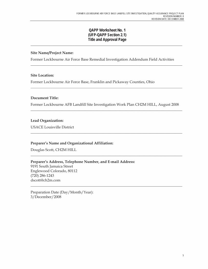
QAPP Worksheet No. 1(UFP-QAPP Section 2.1) Title and Approval Page
_________________________________________________________________________________
Site Name/Project Name:
Former Lockbourne Air Force Base Remedial Investigation Addendum Field Activities _________________________________________________________________________________
Site Location:
Former Lockbourne Air Force Base, Franklin and Pickaway Counties, Ohio _________________________________________________________________________________
Document Title:
Former Lockbourne AFB Landfill Site Investigation Work Plan CH2M HILL, August 2008 _________________________________________________________________________________
Lead Organization:
USACE Louisville District _________________________________________________________________________________
Preparer’s Name and Organizational Affiliation:
Douglas Scott, CH2M HILL _________________________________________________________________________________
Preparer’s Address, Telephone Number, and E-mail Address: 9191 South Jamaica Street Englewood Colorado, 80112 (720) 286-1243 [email protected] _________________________________________________________________________________
Preparation Date (Day/Month/Year): 3/December/2008

FORMER LOCKBOURNE AIR FORCE BASE LANDFILL SITE INVESTIGATION, QUALITY ASSURANCE PROJECT PLAN REVISION NUMBER: 0 REVISION DATE: DECEMBER 2008
6
QAPP Worksheet No. 1(UFP-QAPP Section 2.1) Title and Approval Page
_________________________________________________________________________________ Investigative Organization’s Project Manager/Date:
Signature ______________________________________
Printed Name/Organization:
Robert H. Frank II/CH2M HILL _________________________________________________________________________________
Investigative Organization’s Project QC Director/Date:
Signature ______________________________________
Printed Name/Organization:
Julie Schucker/CH2M HILL _________________________________________________________________________________
Lead Organization’s Project Manager/Date:
Signature ______________________________________
Printed Name/Organization:
Douglas Meadors/USACE Louisville District
_________________________________________________________________________________
Other Approval Signatures/Date:
Signature ______________________________________
Printed Name/Title:
Douglas Malik/CH2M HILL – Program Director
_________________________________________________________________________________

FORMER LOCKBOURNE AIR FORCE BASE LANDFILL SITE INVESTIGATION, QUALITY ASSURANCE PROJECT PLAN REVISION NUMBER: 0
REVISION DATE: DECEMBER 2008
7
QAPP Worksheet No. 2 (UFP-QAPP Section 2.2.4)
QAPP Identifying Information Site Name/Project Name: Former Lockbourne Air Force Base, Former Landfill Site Investigation Activities
Title: Former Lockbourne AFB Landfill Site Investigation Work Plan CH2M HILL, August 2008
Site Location: Former Lockbourne Air Force Base, Franklin and Pickaway Counties, Ohio
Revision Number: 0
Site Number/Code: Revision Date: December 2008
Contractor Name: CH2M HILL Page 7 of 117 Contractor Number: W912QR-04-D-0020 Contract Title: USACE, Louisville District
Work Assignment Number: 0034
1. Identify regulatory program: Comprehensive Environmental Response, Compensation,
and Liability Act (CERCLA)
2. Identify approval entity: USACE Louisville District
3. The QAPP is (select one): Generic Project Specific
4. List dates of scoping sessions that were held:
� January 23-24, 2008: Meeting between CH2M HILL and USACE personnel to discuss risk assessment (RA) review
� February 4 and April 28, 2008: CH2M HILL conducts internal scoping session to discuss QAPP
� February 28, 2008: Meeting with CH2M HILL, USACE, and Ohio EPA personnel to discuss revisions to original RI report
� March 3 and March 17, 2008: Teleconferences between CH2M HILL, USACE, and Ohio EPA personnel to discuss project status
� April 28, 2008: Meeting between CH2M HILL and USACE personnel to discuss new listings of COPCs detected as a result of RA review
� Weekly CH2M HILL internal update teleconferences have been held since April 8, 2008. USACE project managers were invited to participate in these calls, and occasionally USACE Project Manager Douglas Meadors was present.

FORMER LOCKBOURNE AIR FORCE BASE LANDFILL SITE INVESTIGATION, QUALITY ASSURANCE PROJECT PLAN REVISION NUMBER: 0 REVISION DATE: DECEMBER 2008
8
QAPP Worksheet No. 2 (UFP-QAPP Section 2.2.4)
QAPP Identifying Information 5. List dates and titles of QAPP documents written for previous site work, if applicable:
Title Approval Date
Remedial Investigation Report: Former Lockbourne Air Force Base Landfill. Ellis Environmental Group (EEG)
May 2007
Final Site Investigation for Site Investigation – Former Lockbourne Air Force Base Landfill, Rickenbacker Port Authority, Lockbourne, Ohio. Law Engineering and Environmental Services (Law).
November 1995
Supplemental Phase II Environmental Baseline Survey Investigation, Rickenbacker Air National Guard Base, Columbus, OH. IT Corporation
November 1995
6. List organizational partners (stakeholders) and connection with lead organization:
� USACE Louisville District, Lead Agency � Ohio EPA, Regulatory Partner
7. List data users:
� USACE Louisville District, Lead Agency � Ohio EPA, Regulatory Partner � CH2M HILL
8. If any required QAPP elements and required information are not applicable to the project, then circle the omitted QAPP elements and required information on the attached table. Provide an explanation for their exclusions below: Not Applicable

FORMER LOCKBOURNE AIR FORCE BASE LANDFILL SITE INVESTIGATION, QUALITY ASSURANCE PROJECT PLAN REVISION NUMBER: 0
REVISION DATE: DECEMBER 2008
9
QAPP Worksheet No. 2 (UFP-QAPP Section 2.2.4)
QAPP Identifying Information
Identify where each required QAPP element is located in the QAPP (provide section, worksheet, table, or figure number) or other project planning documents (provide complete document title, date, section number, page numbers, and location of the information in the document). Type “NA” for the QAPP elements that are not applicable to the project and provide an explanation in the QAPP.
QAPP Worksheet No. 2 (UFP-QAPP Section 2.2.4)
QAPP Identifying InformationRequired QAPP Element(s) and Corresponding
QAPP Section(s) Required Information
Optional QAPP Worksheet # in QAPP
Workbook
Project Management and Objectives
2.1 Title and Approval Page - Title and Approval Page Worksheet No. 1
2.2 Document Format and Table of Contents 2.2.1 Document Control Format 2.2.2 Document Control Numbering System 2.2.3 Table of Contents 2.2.4 QAPP Identifying Information
- Table of Contents - QAPP Identifying Information
Worksheet No. 2
2.3 Distribution List and Project Personnel Signoff Sheet
2.3.1 Distribution List 2.3.2 Project Personnel Signoff Sheet
- Distribution List - Project Personnel Sign-Off Sheet
Worksheet No. 3 Worksheet No. 4
2.4 Project Organization 2.4.1 Project Organizational Chart 2.4.2 Communication Pathways 2.4.3 Personnel Responsibilities and
Qualifications 2.4.4 Special Training Requirements and
Certification
- Project Organizational Chart - Communication Pathways - Personnel Responsibilities and
Qualifications Table - Special Personnel Training
Requirements Table
Worksheet No. 5 Worksheet No. 6 Worksheet No. 7 Worksheet No. 8
2.5 Project Planning/Problem Definition 2.5.1 Project Planning (Scoping) 2.5.2 Problem Definition, Site History, and
Background
- Project Planning Session Documentation
- Project Scoping Session Participants Sheet
- Problem Definition, Site History, and Background
- Site Maps (historical and present)
Worksheet No. 9 Worksheet No. 10 Worksheet No. 13
2.6 Project Quality Objectives (PQOs) and Measurement Performance Criteria
2.6.1 Development of Project Quality Objectives Using the Systematic Planning Process
2.6.2 Measurement Performance Criteria
- Site-Specific PQOs - Measurement Performance
Criteria Table
Worksheet No. 11 Worksheet No. 12
2.7 Secondary Data Evaluation - Sources of Secondary Data and Information
- Secondary Data Criteria and Limitations Table
Worksheet No. 13
2.8 Project Overview and Schedule 2.8.1 Project Overview 2.8.2 Project Schedule
- Summary of Project Tasks - Reference Limits and Evaluation
Table - Project Schedule/Timeline Table
Worksheet No. 14 Worksheet No. 15 Worksheet No. 16

FORMER LOCKBOURNE AIR FORCE BASE LANDFILL SITE INVESTIGATION, QUALITY ASSURANCE PROJECT PLAN REVISION NUMBER: 0 REVISION DATE: DECEMBER 2008
10
QAPP Worksheet No. 2 (UFP-QAPP Section 2.2.4)
QAPP Identifying InformationRequired QAPP Element(s) and Corresponding
QAPP Section(s) Required Information
Optional QAPP Worksheet # in QAPP
Workbook
Measurement/Data Acquisition
3.1 Sampling Tasks 3.1.1 Sampling Process Design and Rationale 3.1.2 Sampling Procedures and Requirements 3.1.2.1 Sampling Collection Procedures 3.1.2.2 Sample Containers, Volume, and
Preservation 3.1.2.3 Equipment/Sample Containers Cleaning and Decontamination Procedures 3.1.2.4 Field Equipment Calibration, Maintenance, Testing, and Inspection Procedures 3.1.2.5 Supply Inspection and Acceptance Procedures 3.1.2.6 Field Documentation Procedures
- Sampling Design and Rationale - Sample Location Map - Sampling Locations and
Methods/SOP Requirements Table
- Analytical Methods/SOP Requirements Table
- Field Quality Control Sample Summary Table
- Sampling SOPs - Project Sampling SOP
References Table - Field Equipment Calibration,
Maintenance, Testing, and Inspection Table
Worksheet No. 17 Worksheet No. 18 Worksheet No. 19 Worksheet No. 20 Worksheet No. 21 Worksheet No. 22
3.2 Analytical Tasks 3.2.1 Analytical SOPs 3.2.2 Analytical Instrument Calibration
Procedures 3.2.3 Analytical Instrument and Equipment
Maintenance, Testing, and Inspection Procedures
3.2.4 Analytical Supply Inspection and Acceptance Procedures
- Analytical SOPs - Analytical SOP References Table - Analytical Instrument Calibration
Table - Analytical Instrument and
Equipment Maintenance, Testing, and Inspection Table
Worksheet No. 23 Worksheet No. 24 Worksheet No. 25
3.3 Sample Collection Documentation, Handling, Tracking, and Custody Procedures
3.3.1 Sample Collection Documentation 3.3.2 Sample Handling and Tracking System 3.3.3 Sample Custody
- Sample Collection Documentation Handling, Tracking, and Custody SOPs
- Sample Container Identification - - Example Chain-of-Custody Form
and Seal
Worksheet No. 26 Worksheet No. 27
3.4 Quality Control Samples 3.4.1 Sampling Quality Control Samples 3.4.2 Analytical Quality Control Samples
- QC Samples Table -
Worksheet No. 28
3.5 Data Management Tasks 3.5.1 Project Documentation and Records 3.5.2 Data Package Deliverables 3.5.3 Data Reporting Formats 3.5.4 Data Handling and Management 3.5.5 Data Tracking and Control
- Project Documents and Records Table
- Analytical Services Table -
Worksheet No. 29 Worksheet No. 30
Assessment/Oversight
4.1 Assessments and Response Actions 4.1.1 Planned Assessments 4.1.2 Assessment Findings and Corrective Action
Responses
- Assessments and Response Actions
- Planned Project Assessments Table
- - Assessment Findings and
Corrective Action Responses Table
Worksheet No. 31 Worksheet No. 32
4.2 QA Management Reports - QA Management Reports Table Worksheet No. 33
4.3 Final Project Report`

FORMER LOCKBOURNE AIR FORCE BASE LANDFILL SITE INVESTIGATION, QUALITY ASSURANCE PROJECT PLAN REVISION NUMBER: 0
REVISION DATE: DECEMBER 2008
11
QAPP Worksheet No. 2 (UFP-QAPP Section 2.2.4)
QAPP Identifying InformationRequired QAPP Element(s) and Corresponding
QAPP Section(s) Required Information
Optional QAPP Worksheet # in QAPP
Workbook
Data Review
5.1 Overview
5.2 Data Review Steps 5.2.1 Step I: Verification 5.2.2 Step II: Validation 5.2.2.1 Step IIa Validation Activities 5.2.2.2 Step IIb Validation Activities 5.2.3 Step III: Usability Assessment 5.2.3.1 Data Limitations and Actions from
Usability Assessment 5.2.3.2 Activities
- Verification (Step I) Process Table - Validation (Steps IIa and IIb)
Process Table - Validation (Steps IIa and IIb)
Summary Table - Usability Assessment
Worksheet No. 34 Worksheet No. 35 Worksheet No. 36 Worksheet No. 37
5.3 Streamlining Data Review 5.3.1 Data Review Steps To Be Streamlined 5.3.2 Criteria for Streamlining Data Review 5.3.3 Amounts and Types of Data Appropriate for
Streamlining
Worksheet No. 35

FORMER LOCKBOURNE AIR FORCE BASE LANDFILL SITE INVESTIGATION, QUALITY ASSURANCE PROJECT PLAN REVISION NUMBER: 0 REVISION DATE: DECEMBER 2008
12
QAPP Worksheet No. 3(UFP-QAPP Manual Section 2.3.1)
Distribution List List those entities that will receive copies of the approved QAPP, subsequent QAPP revisions, addenda, and amendments will be sent.
Worksheet Not Applicable (State Reason)
Distribution List QAPP Recipients Title Organization Telephone Number Fax Number E-mail Address
Douglas Meadors Project Manager USACE Louisville District
502-315-6345 [email protected]
Jay Trumble Project Manager USACE Louisville District
502-315-6349 [email protected]
Kari Meier Project Chemist USACE Louisville District
502-315-6316 [email protected]
Diana L. Bynum Remedial Project Manager Ohio EPA 614-728-3826 614-728-3898 [email protected]
Robert H. Frank II CH2M HILL Project Manager
CH2M HILL 937-220-2911 937-228-7572 [email protected]
Devamita Chattopadhyay Analytical Sampling Support
CH2M HILL 937-220-2959 [email protected]
Susan Garlic Analytical Sampling Support
CH2M HILL 937-228-3180 [email protected]
Eric Korthals Laboratory Project Manager
CT Laboratories 608-356-2760 [email protected]
Marcia McGinnity Laboratory Project Manager
Empirical Laboratories 615-345-1115 [email protected]
Rich Amano Principal Chemist Laboratory Data Consultants Inc.
760-634-0437 [email protected]
This distribution list shows the primary stakeholder agency leads and project team members. Others, as assigned by the stakeholders and lead contractor (CH2M HILL), may also receive the QAPP and associated documents.

FORMER LOCKBOURNE AIR FORCE BASE LANDFILL SITE INVESTIGATION, QUALITY ASSURANCE PROJECT PLAN REVISION NUMBER: 0
REVISION DATE: DECEMBER 2008
13
QAPP Worksheet No. 4-1(UFP-QAPP Manual Section 2.3.2) Project Personnel Sign-Off Sheet
Have copies of this form signed by key project personnel from each organization to indicate that they have read the applicable sections of the QAPP and will perform the tasks as described. Ask each organization to forward signed sheets to the central project file.
Worksheet Not Applicable (State Reason)
Project Personnel Sign-Off Sheet
Organization: USACE Louisville District
Project Personnel Title Telephone Number Signature Date QAPP Read
Douglas Meadors USACE Project Manager 502-315-6345
Jay Trumble USACE Project Manager 502-315-6349
Kari Meier USACE Project Chemist 502-315-6316

FORMER LOCKBOURNE AIR FORCE BASE LANDFILL SITE INVESTIGATION, QUALITY ASSURANCE PROJECT PLAN REVISION NUMBER: 0 REVISION DATE: DECEMBER 2008
14
QAPP Worksheet No. 4-3 (UFP-QAPP Manual Section 2.3.2) Project Personnel Sign-Off Sheet
Have copies of this form signed by key project personnel from each organization to indicate that they have read the applicable sections of the QAPP and will perform the tasks as described. Ask each organization to forward signed sheets to the central project file.
Project Personnel Sign-Off Sheet
Organization: CH2M HILL
Project Personnel Title Telephone Number Signature Date QAPP Read
Douglas Malik Program Director 724-935-7559
Doug Scott Project Chemist/QAPP Preparer 720-286-1243
Robert H. Frank II CH2M HILL Project Manager 937-220-2911
Dan Moore Data Management Lead 314-421-0313
FORMER LOCKBOURNE AIR FORCE BASE LANDFILL SITE INVESTIGATION, QUALITY ASSURANCE PROJECT PLAN REVISION NUMBER: 0
REVISION DATE: DECEMBER 2008
15
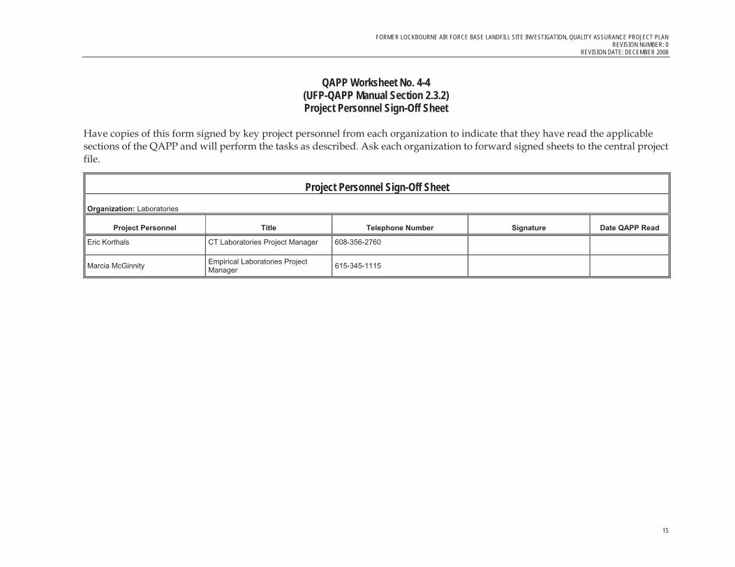
QAPP Worksheet No. 4-4 (UFP-QAPP Manual Section 2.3.2) Project Personnel Sign-Off Sheet
Have copies of this form signed by key project personnel from each organization to indicate that they have read the applicable sections of the QAPP and will perform the tasks as described. Ask each organization to forward signed sheets to the central project file.
Project Personnel Sign-Off Sheet
Organization: Laboratories
Project Personnel Title Telephone Number Signature Date QAPP Read
Eric Korthals CT Laboratories Project Manager 608-356-2760
Marcia McGinnity Empirical Laboratories Project Manager 615-345-1115

FORMER LOCKBOURNE AIR FORCE BASE LANDFILL SITE INVESTIGATION, QUALITY ASSURANCE PROJECT PLAN REVISION NUMBER: 0 REVISION DATE: DECEMBER 2008
16
QAPP Worksheet No. 4-5 (UFP-QAPP Manual Section 2.3.2) Project Personnel Sign-Off Sheet
Have copies of this form signed by key project personnel from each organization to indicate that they have read the applicable sections of the QAPP and will perform the tasks as described. Ask each organization to forward signed sheets to the central project file.
Project Personnel Sign-Off Sheet
Organization: Data validation Third Party
Project Personnel Title Telephone Number Signature Date QAPP Read
Rich Amano Principal Chemist Laboratory Data Consultants Inc
760-634-0437

FORMER LOCKBOURNE AIR FORCE BASE LANDFILL SITE INVESTIGATION, QUALITY ASSURANCE PROJECT PLAN REVISION NUMBER: 0
REVISION DATE: DECEMBER 2008
17
QAPP Worksheet No. 5 (UFP-QAPP Manual Section 2.4.1)
Project Organizational Chart
Doug MeadorsLouisville District PM
Jay TrumbleLouisville District PM
Kari MeierLouisville District Program Chemist
Doug MalikProgram Director
CH2M HILL
Robert FrankProject Manager
CH2M HILL
Doug ScottProject Chemist
CH2M HILL
Eric KorthalsAnalytical Laboratory
CT Laboratories
Marcia McGinnityQA Laboratory
Empirical Laboratories
Susan Garlic and Matt GaleField Team Leads
CH2M HILL
Dan MooreData Management Lead
CH2M HILL
Diana BynumRemedial Project Manager
Ohio EPA
FORMER LOCKBOURNE AIR FORCE BASE LANDFILL SITE INVESTIGATION, QUALITY ASSURANCE PROJECT PLAN REVISION NUMBER: 0 REVISION DATE: DECEMBER 2008
18
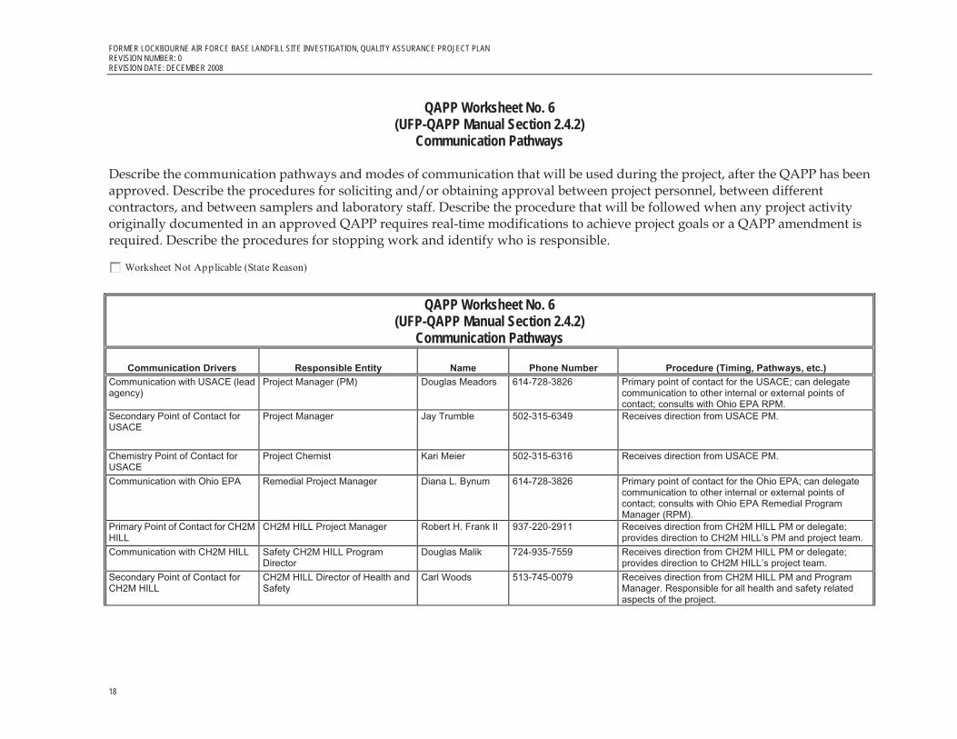
QAPP Worksheet No. 6 (UFP-QAPP Manual Section 2.4.2)
Communication Pathways
Describe the communication pathways and modes of communication that will be used during the project, after the QAPP has been approved. Describe the procedures for soliciting and/or obtaining approval between project personnel, between different contractors, and between samplers and laboratory staff. Describe the procedure that will be followed when any project activity originally documented in an approved QAPP requires real-time modifications to achieve project goals or a QAPP amendment is required. Describe the procedures for stopping work and identify who is responsible.
Worksheet Not Applicable (State Reason)
QAPP Worksheet No. 6 (UFP-QAPP Manual Section 2.4.2)
Communication Pathways
Communication Drivers Responsible Entity Name Phone Number Procedure (Timing, Pathways, etc.) Communication with USACE (lead agency)
Project Manager (PM) Douglas Meadors 614-728-3826 Primary point of contact for the USACE; can delegate communication to other internal or external points of contact; consults with Ohio EPA RPM.
Secondary Point of Contact for USACE
Project Manager Jay Trumble 502-315-6349 Receives direction from USACE PM.
Chemistry Point of Contact for USACE
Project Chemist Kari Meier 502-315-6316 Receives direction from USACE PM.
Communication with Ohio EPA Remedial Project Manager Diana L. Bynum 614-728-3826 Primary point of contact for the Ohio EPA; can delegate communication to other internal or external points of contact; consults with Ohio EPA Remedial Program Manager (RPM).
Primary Point of Contact for CH2M HILL
CH2M HILL Project Manager Robert H. Frank II 937-220-2911 Receives direction from CH2M HILL PM or delegate; provides direction to CH2M HILL’s PM and project team.
Communication with CH2M HILL Safety CH2M HILL Program Director
Douglas Malik 724-935-7559 Receives direction from CH2M HILL PM or delegate; provides direction to CH2M HILL’s project team.
Secondary Point of Contact for CH2M HILL
CH2M HILL Director of Health and Safety
Carl Woods 513-745-0079 Receives direction from CH2M HILL PM and Program Manager. Responsible for all health and safety related aspects of the project.
FORMER LOCKBOURNE AIR FORCE BASE LANDFILL SITE INVESTIGATION, QUALITY ASSURANCE PROJECT PLAN REVISION NUMBER: 0
REVISION DATE: DECEMBER 2008
19
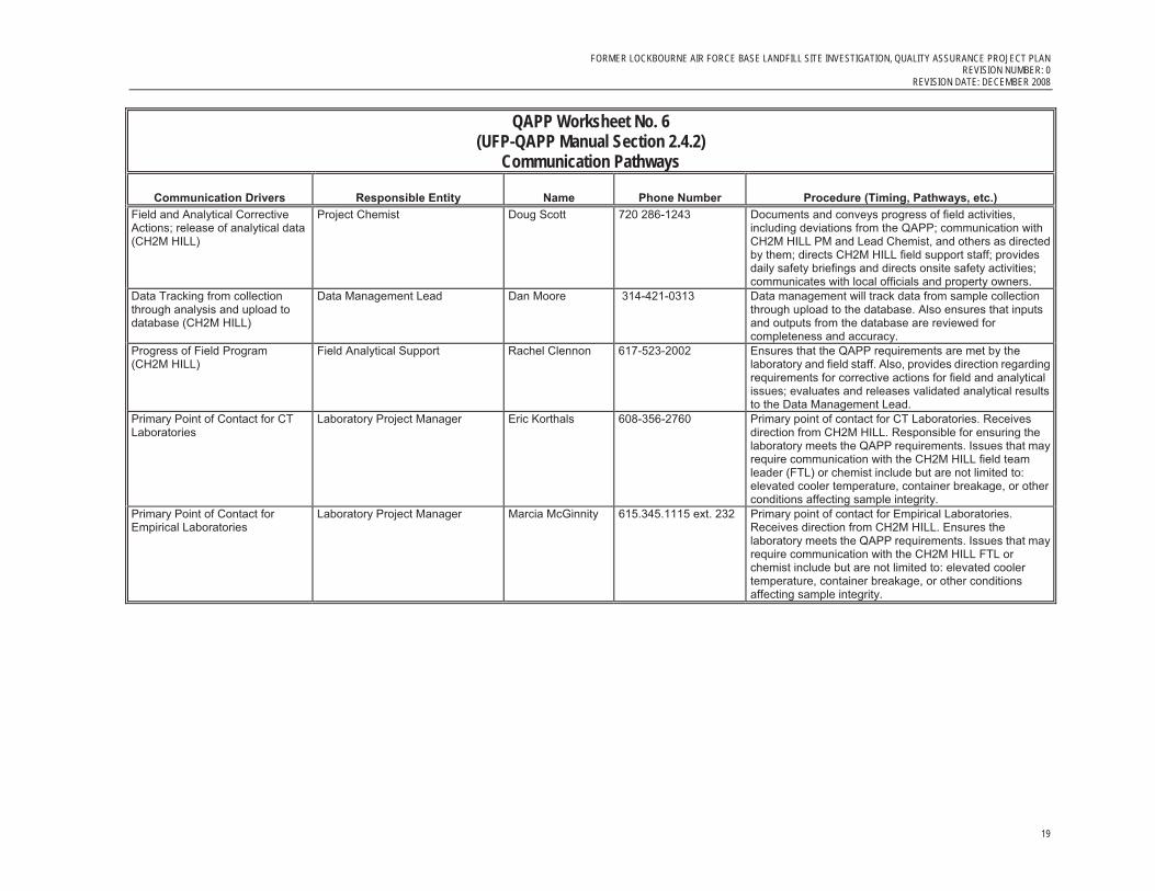
QAPP Worksheet No. 6 (UFP-QAPP Manual Section 2.4.2)
Communication Pathways
Communication Drivers Responsible Entity Name Phone Number Procedure (Timing, Pathways, etc.) Field and Analytical Corrective Actions; release of analytical data (CH2M HILL)
Project Chemist Doug Scott 720 286-1243 Documents and conveys progress of field activities, including deviations from the QAPP; communication with CH2M HILL PM and Lead Chemist, and others as directed by them; directs CH2M HILL field support staff; provides daily safety briefings and directs onsite safety activities; communicates with local officials and property owners.
Data Tracking from collection through analysis and upload to database (CH2M HILL)
Data Management Lead Dan Moore 314-421-0313 Data management will track data from sample collection through upload to the database. Also ensures that inputs and outputs from the database are reviewed for completeness and accuracy.
Progress of Field Program (CH2M HILL)
Field Analytical Support Rachel Clennon 617-523-2002 Ensures that the QAPP requirements are met by the laboratory and field staff. Also, provides direction regarding requirements for corrective actions for field and analytical issues; evaluates and releases validated analytical results to the Data Management Lead.
Primary Point of Contact for CT Laboratories
Laboratory Project Manager Eric Korthals 608-356-2760 Primary point of contact for CT Laboratories. Receives direction from CH2M HILL. Responsible for ensuring the laboratory meets the QAPP requirements. Issues that may require communication with the CH2M HILL field team leader (FTL) or chemist include but are not limited to: elevated cooler temperature, container breakage, or other conditions affecting sample integrity.
Primary Point of Contact for Empirical Laboratories
Laboratory Project Manager Marcia McGinnity 615.345.1115 ext. 232 Primary point of contact for Empirical Laboratories. Receives direction from CH2M HILL. Ensures the laboratory meets the QAPP requirements. Issues that may require communication with the CH2M HILL FTL or chemist include but are not limited to: elevated cooler temperature, container breakage, or other conditions affecting sample integrity.

FORMER LOCKBOURNE AIR FORCE BASE LANDFILL SITE INVESTIGATION, QUALITY ASSURANCE PROJECT PLAN REVISION NUMBER: 0 REVISION DATE: DECEMBER 2008
20
QAPP Worksheet No. 7 (UFP-QAPP Manual Section 2.4.3)
Personnel Responsibilities and Qualifications Table
Identify project personnel associated with each organization, contractor, and subcontractor participating in responsible roles. Include data users, decision-makers, project managers, QA officers, project contacts for organizations involved in the project, project health and safety officers, geotechnical engineers and hydrogeologists, field operation personnel, analytical services, and data reviewers. Identify project team members with an asterisk (*). Attach resume to this worksheet or note the location of the resumes.
Worksheet Not Applicable (State Reason)
QAPP Worksheet No. 7 (UFP-QAPP Manual Section 2.4.3)
Personnel Responsibilities and Qualification Table
Name Title Organizational
Affiliation Responsibilities Education and Experience Qualifications
Douglas Meadors
Project Manager USACE Louisville District
Manages project for the USACE Louisville District M.P.A., Public Administration, Indiana University; MEng., Environmental Engineering, University of Louisville; B.S., Applied Science, University of Louisville, 27 years experience
Jay Trumble
Project Manager USACE Louisville District
Receives direction from USACE PM. Provides direction to CH2M HILL
B.S., Chemical Engineering,12 years experience in Environmental Engineering
Kari Meier Project Chemist USACE Louisville District
Receives direction from USACE PM. Provides direction to CH2M HILL
M.S., Chemistry; Ph.D. Environmental Science/Atmospheric Chemistry, 7 years experience
Robert H. Frank II
CH2M HILL Project Manager
CH2M HILL Provides direction to CH2M HILL’s project team. Tracks the budget and schedule for CH2M HILL personnel
B.S. Natural Resource Conservation Management, 9 years experience CHMM Master Level, No. 13441
Douglas Malik
CH2M HILL Program Director
CH2M HILL Provides technical and administrative guidance to the project team, and direction to the CH2M HILL PM.
M.S., Civil Engineering, State University of New York at Buffalo; MBA, State University of New York at Buffalo; B.S., Civil Engineering, State University of New York at Buffalo
Rachel Clennon
Field Analytical Support
CH2M HILL Documents and conveys progress of field activities, including deviations from the QAPP; communication with CH2M HILL PM and Lead Chemist, and others as directed by them; directs CH2M HILL field support staff; provides daily safety briefings and directs onsite safety activities; communicates with local officials and property owners.
B.S., Geology, Environmental Studies, Tulane University, 5 years experience

FORMER LOCKBOURNE AIR FORCE BASE LANDFILL SITE INVESTIGATION, QUALITY ASSURANCE PROJECT PLAN REVISION NUMBER: 0
REVISION DATE: DECEMBER 2008
21
QAPP Worksheet No. 7 (UFP-QAPP Manual Section 2.4.3)
Personnel Responsibilities and Qualification Table
Name Title Organizational
Affiliation Responsibilities Education and Experience Qualifications
Dan Moore Data Management Lead
CH2M HILL Data management will track data from sample collection through upload to the database. Also responsible to ensure that input/outputs from the database are reviewed for completeness and accuracy
University of Missouri, St. Louis, Chemistry & Math Course Study, 17 years experience
Doug Scott Project Chemist CH2M HILL Responsible to ensure that the QAPP requirements are met by the laboratory and field staff. Also, provides direction regarding requirements for corrective actions for field and analytical issues; oversight of the third party data validation, evaluates and releases validated analytical results to the Data Management Lead.
A.S., Science, 22 years experience
Eric Korthals
Laboratory Project Manager
CT Laboratories Primary point of contact for laboratory M.S., Biology, 25 years experience
Marcia McGinnity
Laboratory Project Manager
Empirical Laboratories
Primary point of contact for Empirical Laboratories. B.S., 1987, Chemistry; 1987, Science Education, North Carolina State University, Raleigh, NC, 11 years of experience
Resumes are maintained by the individuals’ organization and are available upon request; other staff with similar qualifications may be removed, added, or substituted as necessary. .

FORMER LOCKBOURNE AIR FORCE BASE LANDFILL SITE INVESTIGATION, QUALITY ASSURANCE PROJECT PLAN REVISION NUMBER: 0 REVISION DATE: DECEMBER 2008
22
QAPP Worksheet No. 8(UFP-QAPP Manual Section 2.4.4)
Special Personnel Training Requirements Table
Provide the following information for those projects requiring personnel with specialized training. Attach training records and/or certificates to the QAPP or note their location.
Worksheet Not Applicable (State Reason)
QAPP Worksheet No. 8
(UFP-QAPP Manual Section 2.4.4) Special Personnel Training Requirements Table
Project Function
Specialized Training – Title or Description of
CourseTraining Provider
Training Date
Personnel/Groups Receiving Training
Personnel Titles/
Organizational Affiliation
Location of Training Records/Certificates
Lockbourne AFB Former Landfill Environmental Work
Hazwoper 40-hour Training/8 Hour Refresher
Registered Training Organization—Internal CH2M HILL HAZWOPR 8 Hr Refresher Course
08/21/08 Robert H. Frank II
Matt Gale
Susan Garlic
CH2M HILL Project Manager
CH2M HILL Field Team Lead
CH2M HILL Field Team Member
CH2M HILL Human Resources Department
Lockbourne AFB Former Landfill Environmental Work
Hazwoper 40-hour Training/8 Hour Refresher
Registered Training Organization—Internal BBU 8 Hr Refresher Course
10/8/08 BBU BBU Operator BBU Human Resources Department
Lockbourne AFB Former Landfill Environmental Work
3R Training Ben Redmund, CH2M HILL Munitions Response Subject Matter Expert
8/8/08 All field project team members
CH2M HILL Project Team (project manager and field team personnel)
CH2M HILL Human Resources Department
Lockbourne AFB Former Landfill Environmental Work
3R Training Ben Redmund, CH2M HILL Munitions Response Subject Matter Expert
8/8/08 All field project team members
BBU field personnel BBU Human Resources Department
Project team members with the necessary experience and technical skills are chosen to perform required project-specific tasks. Subcontractors chosen to complete tasks such as drilling, laboratory analysis, and data validation will meet project-specific requirements and specifications set forth by CH2M HILL and EPA.

FORMER LOCKBOURNE AIR FORCE BASE LANDFILL SITE INVESTIGATION, QUALITY ASSURANCE PROJECT PLAN REVISION NUMBER: 0
REVISION DATE: DECEMBER 2008
23
QAPP Worksheet No. 9 (UFP-QAPP Manual Section 2.5.1)
Project Scoping Session Participants Sheet
Complete this worksheet for each project scoping session held. Identify project team members who are responsible for planning the project.
Worksheet Not Applicable (State Reason)
On January 23-24, 2008, CH2M HILL and USACE personnel met in Cincinnati, Ohio. Those present were CH2M HILL Project Manager Robert Frank, CH2M HILL Senior Consultants Spence Smith and Scott Hutsell, and USACE Project Managers Douglas Meadors and Jay Trumble. These meetings were held to discuss the RA review and the formulation of a revised COPC list.
On February 4 and April 25, 2008, scoping sessions for the RI QAPP were held. Participants in these meetings were CH2M HILL project team members: Robert Frank, CH2M HILL Project Manager, Douglas Scott, CH2M HILL Project Chemist, and Matt Gale, CH2M HILL Staff Consultant. These two meetings were held to determine the data quality objectives (DQOs) for the project, review of the scoped work to be delivered, and the methods by which the work can be most efficiently delivered.
On February 28, 2008, CH2M HILL, USACE, and Ohio EPA personnel met in Columbus, Ohio. Participants were CH2M HILL Project Manager Robert Frank, CH2M HILL Senior Consultants Spence Smith and Scott Hutsell, USACE Project Managers Douglas Meadors and Jay Trumble, and Ohio EPA Remedial Project Manager Diana Bynum. This meeting was held to discuss Ohio EPA comments on the original RI Report and the efforts by CH2M HILL to address these comments for document approval.
On March 3 and March 27, 2008, CH2M HILL, USACE, and Ohio EPA personnel held two teleconferences. Participants were CH2M HILL Project Manager Robert Frank, CH2M HILL Senior Consultants Spence Smith and Scott Hutsell, USACE Project Managers Douglas Meadors and Jay Trumble, and Ohio EPA Remedial Project Manager Diana Bynum. The purpose of these calls was to present the technical approach to the work plan for the site investigation to Ohio EPA.
On April 28, 2008, CH2M HILL Project Manager Robert Frank, CH2M HILL Senior Consultants Spence Smith and Scott Hutsell, CH2M HILL Project Chemist Doug Scott, and USACE Project Managers Douglas Meadors and Jay Trumble held a teleconference to discuss new listings of COPCs detected due to RA review.
On July 9, 2008, CH2M HILL Project Manager Robert Frank, CH2M HILL Senior Consultant Spence Smith, and USACE Project Managers Douglas Meadors, Brooks Evens, and Jay Trumble, and Ohio EPA RPM Diana Bynum held a teleconference to discuss Ohio EPA comments on the work plan.

FORMER LOCKBOURNE AIR FORCE BASE LANDFILL SITE INVESTIGATION, QUALITY ASSURANCE PROJECT PLAN REVISION NUMBER: 0 REVISION DATE: DECEMBER 2008
24
QAPP Worksheet No. 9 (UFP-QAPP Manual Section 2.5.1)
Project Scoping Session Participants Sheet
On October 9, 2008, CH2M HILL Project Manager Robert Frank, CH2M HILL CH2M HILL Project Chemist Doug Scott, and USACE Project Manager Brooks Evens, USACE Chemist Kari Meier, and Ohio EPA RPM Diana Bynum held a teleconference to discuss Ohio EPA comments on the QAPP.
Weekly internal update teleconferences have been held since April 8, 2008. USACE project managers were invited to participate in these calls, and occasionally USACE Project Manager Douglas Meadors is present. Other participants vary, but have included: CH2M HILL Project Manager Robert Frank, CH2M HILL Senior Consultants Spence Smith and Scott Hutsell, CH2M HILL Project Chemist Doug Scott, and CH2M HILL Staff Consultants Matt Gale and Rachel Clennon. These meetings provide weekly updates by team members and discuss ongoing project progress internally and with USACE personnel.
Project Scoping Session Participants Sheet Project Name: Former Lockbourne Air Force Base Remedial Investigation Addendum Fieldwork ActivitiesProjected Date(s) of Sampling: September 2008 Project Manager: Robert Frank
Site Name: Former Lockbourne Air Force Base Site Location: Former Lockbourne Air Force Base, Franklin and Pickaway Counties, OH
Date of Session: Scoping Session Purpose:
Name Title Affiliation Phone No. E-mail Address Project Role
Douglas Meadors Project Manager USACE 502-315-6345 [email protected]
USACE Project Manager
(PM)
Jay Trumble Project Manager USACE 502-315-6349 [email protected]
USACE Project Manager
(PM)
Diana L. Bynum Remedial Project
Manager Ohio EPA 614-728-3778 [email protected]
Ohio EPA Remedial Project
Manager
Robert H. Frank II Project Manager CH2M HILL 937-220-2911 [email protected] CH2M HILL
Project Manager
Douglas Scott Project Chemist CH2M HILL 720-286-1243 [email protected] CH2M HILL
Project Chemist
Spence Smith Senior Consultant CH2M HILL 617-523-2002 [email protected] CH2M HILL
Senior Consultant
Scott Hutsell Senior Consultant CH2M HILL 517-347-3404 [email protected] CH2M HILL
Senior Consultant
Matt Gale Staff Consultant CH2M HILL 937-220-2905 [email protected] CH2M HILL Staff
Consultant
Rachel Clennon Staff Consultant CH2M HILL 617-523-2002 [email protected] CH2M HILL Staff
Consultant

FORMER LOCKBOURNE AIR FORCE BASE LANDFILL SITE INVESTIGATION, QUALITY ASSURANCE PROJECT PLAN REVISION NUMBER: 0
REVISION DATE: DECEMBER 2008
25
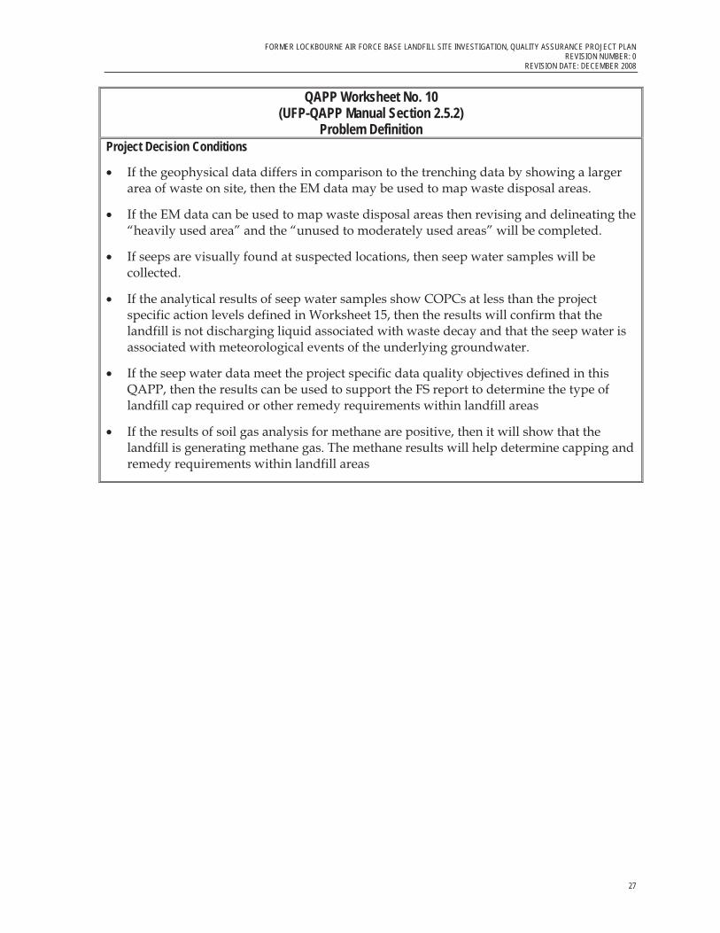
QAPP Worksheet No. 10(UFP-QAPP Manual Section 2.5.2)
Problem Definition
Clearly define the problem and the environmental questions that should be answered for the current investigation and develop the project decision “If…, then…” statements in the QAPP, linking data results with possible actions. The prompts below are meant to help the project team define the problem. They are not comprehensive.
QAPP Worksheet No. 10(UFP-QAPP Manual Section 2.5.2)
Problem Definition Detailed site history and investigation background are presented in the Introduction to this document. This section includes a problem definition and project objectives designed to address this problem.
PROBLEM DEFINITION Information is needed to better characterize the limits of waste disposal in the areas believed to have been used for waste disposal (the “heavily used” and “unused to moderately used” areas), evaluate other areas historically cleared of vegetation where construction and demolition debris may have been placed, further evaluate and sample seep water on the eastern and western sides of the former landfill, and evaluate methane in soil vapor in the former landfill. Previous seep sampling has produced poor quality data, primarily associated with high turbidity seep water, and led CH2M HILL to question the past sampling methodology and thereby adjust the current seep sampling approach to address these concerns and improve data quality.
The objectives of this investigation are to collect supporting information for the development of remedial alternatives, and have agreement by all parties as to this remedy. CH2M HILL selected trench locations intended to provide 1) better characterization of the limits of waste disposal in the northern part of the heavily used area and its relationship to geophysical (electromagnetic induction [EM]) anomalies, and 2) evaluation of the extent of waste disposal in the south end of the heavily used area, and 3) evaluation of EM anomalies in the areas identified as being unused-to-moderately used and possibly involving disposal of construction debris (for example, asphalt). Sampling efforts, of both seep water and methane gas, will further the understanding of the impacted areas and support the evaluation of selecting the appropriate remedial option.
Geophysical survey work involving EM is planned to be repeated in a few areas such that recent geophysical data may be compared with results from trenching, potentially allowing EM data to be used to map waste disposal. The information gathered during this investigation will also be used to help delineate and revise the designated “heavily used area” and the “unused to moderately used areas”.
TrenchingThe objectives of the trenching effort consist of the following components:

FORMER LOCKBOURNE AIR FORCE BASE LANDFILL SITE INVESTIGATION, QUALITY ASSURANCE PROJECT PLAN REVISION NUMBER: 0 REVISION DATE: DECEMBER 2008
26
QAPP Worksheet No. 10(UFP-QAPP Manual Section 2.5.2)
Problem Definition � Better characterize the limits of waste disposal in the areas believed to have been used of
for solid waste disposal
� Evaluate other areas historically cleared of vegetation where construction and demolition debris may have been placed; The information gathered during this investigation will be used to help delineate and revise the designated “heavily used area” and the “unused to moderately used areas”
Geophysical Investigation Geophysical survey work involving EM induction is planned to be repeated in a few areas with the following objectives:
� Recent geophysical data may be compared with results from trenching, potentially allowing EM data to be used to map waste disposal.
� To help delineate and revise the designated “heavily used area” and the “unused to moderately used areas
Seep Water The seep water samples, to be collected along the slope of the “heavily used” area of the landfill, will be analyzed for a defined list of VOCs, SVOCs, dioxins/furans, MNA parameters and pH. The objectives of the seep sampling effort consist of the following components:
� The objective of the seep water sampling and analysis is support an understanding of the conditions of the seep water and whether the water shows characteristics of liquid associated with waste decay. Seep sample collection is to help USACE determine if the sample locations called seeps within historical documentation are seeps associated with the groundwater, or if they are points where rainwater from meteorological events exit the landfill. The MNA parameters (dissolved metals (Mn/Fe), NO2/NO3 as nitrogen, sulfate, chloride, methane, ethane, ethane, alkalinity, and total organic carbon) have been proposed because they will help determine if the seep water is associated with meteorological events of the underlying groundwater by showing whether or not the byproducts of waste degradation are present within the samples collected.
� Use seep sampling data in the FS report to determine the type of cap required.
Methane Gas � Determine if the landfill is generating methane gas.
� Use this additional information to help determine capping and remedy requirements within landfill areas.
FORMER LOCKBOURNE AIR FORCE BASE LANDFILL SITE INVESTIGATION, QUALITY ASSURANCE PROJECT PLAN REVISION NUMBER: 0
REVISION DATE: DECEMBER 2008
27
QAPP Worksheet No. 10(UFP-QAPP Manual Section 2.5.2)
Problem Definition Project Decision Conditions
� If the geophysical data differs in comparison to the trenching data by showing a larger area of waste on site, then the EM data may be used to map waste disposal areas.
� If the EM data can be used to map waste disposal areas then revising and delineating the “heavily used area” and the “unused to moderately used areas” will be completed.
� If seeps are visually found at suspected locations, then seep water samples will be collected.
� If the analytical results of seep water samples show COPCs at less than the project specific action levels defined in Worksheet 15, then the results will confirm that the landfill is not discharging liquid associated with waste decay and that the seep water is associated with meteorological events of the underlying groundwater.
� If the seep water data meet the project specific data quality objectives defined in this QAPP, then the results can be used to support the FS report to determine the type of landfill cap required or other remedy requirements within landfill areas
� If the results of soil gas analysis for methane are positive, then it will show that the landfill is generating methane gas. The methane results will help determine capping and remedy requirements within landfill areas

FORMER LOCKBOURNE AIR FORCE BASE LANDFILL SITE INVESTIGATION, QUALITY ASSURANCE PROJECT PLAN REVISION NUMBER: 0 REVISION DATE: DECEMBER 2008
28
QAPP Worksheet No. 11 (UFP-QAPP Manual Section 2.6.1)
Project Quality Objectives/Systematic Planning Process Statements
Use this worksheet to develop project quality objectives (PQOs) in terms of type, quantity, and quality of data determined using a systematic planning process. Provide a detailed discussion of PQOs in the QAPP. List PQOs in the form of qualitative and quantitative statements. These statements should answer questions such as those listed below. These questions are examples only; however, they are neither inclusive nor appropriate for all projects.
Worksheet Not Applicable (State Reason)
QAPP Worksheet No. 11(UFP-QAPP Manual Section 2.6.1)
Project Quality Objectives/Systematic Planning Process Statements
Trenching and Geophysical Investigation
Who will use the data?
Ohio EPA, USACE, and CH2M HILL
What will the data be used for?
The trenching and geophysical information will be used to better characterize the limits of waste disposal in the areas believed to have been used of for solid waste disposal; and evaluate other areas historically cleared of vegetation where construction and demolition debris may have been placed to help delineate and revise the designated “heavily used area” and the “unused to moderately used areas”. Geophysical survey work involving EM is planned to be repeated in a few areas where trenching will occur such that geophysical data may be compared with results from trenching. These data are expected to support an evaluation of EM data, including new and previously collected, and its use as an aid in mapping horizontal waste disposal boundaries.
What types of data are needed?
Using a flame ionization detector (FID), screening level qualitative data will be generated during the trenching activities as part of the field activities conducted by CH2M HILL for health and safety purposes during fieldwork only. Material removed from the trench locations will be screened with a FID, placed on visqueen sheets adjacent to the trench, and covered. If the readings on the FID are above action levels (as dictated by the project-specific accident prevention plan (APP) consistent with the USACE Safety and Health Requirements Manual (EM 385-1-1, November 2003; and ER 385-1-92, Appendix C, Safety and Health Elements for Hazardous Toxic Radioactive Waste Activities, 1 September 2000) then excavation activities will immediately stop.

FORMER LOCKBOURNE AIR FORCE BASE LANDFILL SITE INVESTIGATION, QUALITY ASSURANCE PROJECT PLAN REVISION NUMBER: 0
REVISION DATE: DECEMBER 2008
29
QAPP Worksheet No. 11(UFP-QAPP Manual Section 2.6.1)
Project Quality Objectives/Systematic Planning Process Statements
How “good” does the data need to be in order to support the environmental decision? Field screening level data quality will be sufficient to meet the project data use.
How much data are needed? Figure 2-1 of the Former Lockbourne AFB Landfill Site Investigation Work Plan CH2M HILL, August 2008 indicates the number and location of trenches to be excavated. Sufficient documentation will be collected during trenching activities to meet project objectives. Where, when, and how should the data be collected/generated? Approximately seventeen trenches will be excavated in predetermined locations, as shown in Figure 2-1 in the Work Plan. The rationale for each sampling location and a brief description of each is also presented in Table 2-1 in the Work Plan.
Using an excavator or similar-type of equipment, CH2M HILL will excavate test trenches in accordance with the designated Work Plan and appropriate Field SOP (Former Lockbourne AFB Landfill Site Investigation Work Plan CH2M HILL, August 2008, Appendix C, SOP-01) to a depth of between 9 and 10 feet. If CH2M HILL observes the water table before reaching that depth, excavation activities will be discontinued at that location. CH2M HILL will conduct excavations in 3-foot lifts, and record soil observations at intervals of 0-to-3, 3-to-6, and 6-to-9 feet. Material removed from the trenches will be screened as described above. After screening and documentation of the trench, the material removed during trenching will then be replaced in the reverse order of its removal, so that the last lift (6-9 feet) is replaced first an the first lift (0-3 feet) is replaced into the trench last. The excavated material will be replaced in the trenches, presuming that the work will not require any additional backfill to restore the site to the approximate existing grade. As appropriate, CH2M HILL will seed these areas, covering them with straw, so as to encourage the re-growth of grass. CH2M HILL will also survey the four corners of each trench to sub meter accuracy using GPS technology, and will map those using Ohio state plane coordinates.
In the event that obvious contamination is observed during trenching activities, such as liquids, petroleum products or FID soil screening results above action levels, CH2M HILL will employ the Corps of Engineers Rapid Response Plan. This plan is detailed in the Former Lockbourne AFB Landfill Site Investigation Work Plan CH2M HILL, August 2008, Section 1.7, and the project health and safety plan (HASP). In the event that an unforeseen condition is uncovered such as a buried container or the presence of liquid petroleum or fuel or a similar unforeseen condition requiring special handling, CH2M HILL will immediately inform the Corps of Engineers Louisville District, Contracting Officer’s Representative (COR). CH2M HILL will stop work at the location and take appropriate action to safely place warning tape or a sign at the location. For any unforeseen situations that may have significant impacts on, human life, public health or the environment the Corps of Engineers has designated the Corps of Engineers Omaha District as the District for rapid response activities.

FORMER LOCKBOURNE AIR FORCE BASE LANDFILL SITE INVESTIGATION, QUALITY ASSURANCE PROJECT PLAN REVISION NUMBER: 0 REVISION DATE: DECEMBER 2008
30
QAPP Worksheet No. 11(UFP-QAPP Manual Section 2.6.1)
Project Quality Objectives/Systematic Planning Process Statements
The Rapid Response Program Office has contracts with local vendors that have equipment that can quickly respond to an unforeseen condition such as the rupture of a buried container. A response would address impacts to human life, public health, and/or the environment.
Who will collect and generate the data?CH2M HILL will collect the screening data resulting from the trenching activities.
How will the data be reported? At the conclusion of the field activities, a Trenching and Supplemental Sampling Report will be completed to document the sampling activities. The Trenching and Supplemental Sampling Report will include text, tables, and figures including a description of the field activities, tables presenting data collected, and figures presenting locations of associated relevant activities.
A photograph documentation log will also be included along with this report. Each photograph will include the date and time the photograph was taken, the photographer’s name, the direction of the photograph, the photograph’s electronic file name, and any relevant comments.
How will the data be archived? Electronic data (database management system and project GIS) is routinely backed-up by CH2M HILL internal database systems. In addition, electronic data will be archived onto CD-ROM or DVD+R media on a monthly basis. Project reports will be archived on CD-ROM or DVD +R media and stored in the project file. All materials will be archived for 7 years after the remedial action completion.
Seep Water Samples
Who will use the data? Ohio EPA, USACE, and CH2M HILL
What will the data be used for? The seep water data will be used to verify if the “heavily used” area of the landfill is not leaching fluid and the seeps are related to infiltration of surface water and rainfall. The resulting data set will be used to aid in the determination of a remedial alternative (cap).
What types of data are needed? Samples will be collected for seep water and taken to an offsite laboratory, CT Laboratories, for analysis of COPCs of VOCs, SVOC/PAHs, dioxin/furans, metals, and general MNA parameters, including nitrate/nitrite as nitrogen, methane, ethane and ethene, chloride, sulfate, alkalinity and total organic carbon. Dioxin/furans will be subcontracted by CT Laboratories to TestAmerica Laboratories in Knoxville, Tennessee. A complete listing of
FORMER LOCKBOURNE AIR FORCE BASE LANDFILL SITE INVESTIGATION, QUALITY ASSURANCE PROJECT PLAN REVISION NUMBER: 0
REVISION DATE: DECEMBER 2008
31
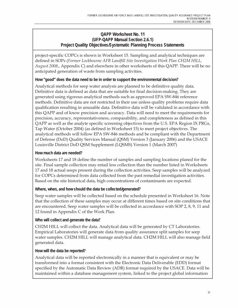
QAPP Worksheet No. 11(UFP-QAPP Manual Section 2.6.1)
Project Quality Objectives/Systematic Planning Process Statements
project-specific COPCs is shown in Worksheet 15. Sampling and analytical techniques are defined in SOPs (Former Lockbourne AFB Landfill Site Investigation Work Plan CH2M HILL, August 2008,, Appendix C) and elsewhere in other worksheets of this QAPP. There will be no anticipated generation of waste from sampling activities.
How “good” does the data need to be in order to support the environmental decision? Analytical methods for seep water analysis are planned to be definitive quality data. Definitive data is defined as data that are suitable for final decision-making. They are generated using rigorous analytical methods such as approved EPA SW-846 reference methods. Definitive data are not restricted in their use unless quality problems require data qualification resulting in unusable data. Definitive data will be validated in accordance with this QAPP and of know precision and accuracy. Data will need to meet the requirements for precision, accuracy, representativeness, comparability, and completeness as defined in this QAPP as well as the analyte specific screening objectives from the U.S. EPA Region IX PRGs, Tap Water (October 2004) (as defined in Worksheet 15) to meet project objectives. The analytical methods will follow EPA SW-846 methods and be compliant with the Department of Defense (DoD) Quality Services Manual (QSM) Version 3 (January 2006) and the USACE Louisville District DoD QSM Supplement (LQSMS) Version 1 (March 2007)
How much data are needed? Worksheets 17 and 18 define the number of samples and sampling locations planed for the site. Final sample collection may entail less collection than the number listed in Worksheets 17 and 18 actual seeps present during the collection activities. Seep samples will be analyzed for COPCs determined from data collected from the past remedial investigation activities. Based on the site historical data, high concentrations of contaminants are expected.
Where, when, and how should the data be collected/generated? Seep water samples will be collected based on the schedule presented in Worksheet 16. Note that the collection of these samples may occur at different times based on site conditions that are encountered. Seep water samples will be collected in accordance with SOP 2, 8, 9, 11 and 12 found in Appendix C of the Work Plan.
Who will collect and generate the data? CH2M HILL will collect the data. Analytical data will be generated by CT Laboratories. Empirical Laboratories will generate data from quality assurance split samples for seep water samples. CH2M HILL will manage analytical data. CH2M HILL will also manage field generated data.
How will the data be reported? Analytical data will be reported electronically in a manner that is equivalent or may be transformed into a format consistent with the Electronic Data Deliverable (EDD) format specified by the Automatic Data Review (ADR) format required by the USACE. Data will be maintained within a database management system, linked to the project global information

FORMER LOCKBOURNE AIR FORCE BASE LANDFILL SITE INVESTIGATION, QUALITY ASSURANCE PROJECT PLAN REVISION NUMBER: 0 REVISION DATE: DECEMBER 2008
32
QAPP Worksheet No. 11(UFP-QAPP Manual Section 2.6.1)
Project Quality Objectives/Systematic Planning Process Statements
system (GIS) data. The Laboratory shall transmit the data in the hard copy format as a complete Level III type data as well as include full supporting raw data. To the extent possible, all applicable data such as sample results, laboratory QC samples including (but not limited to) surrogates, LCS. MS/MSD, calibrations and blanks must be provided on summary format pages. All LQSMS specific laboratory checklist will apply and must be provided with the data deliverable. Documentation and reports specified in this QAPP will be retained in Adobe PDF format.
EPA Level III data will contain the following summarized data forms. All supporting raw data will be included as well as the following summary forms:
� Cover letter � Table of contents � Chain of custody form dated and signed by the laboratory � Sample receipt checklist and login information � Summary of samples received that correlates field sample ids with the laboratory ids � Laboratory qualifier flags and definitions � Field identification number � Date received � Date prepared � Date analyzed (and time of analysis if the holding time is less than or equal to 48 hours) � Preparation and analytical methods � Result for each analyte (dry weight basis for soils) � Percent solids results for soil samples � Dilution factor (provide both diluted and undiluted results when available) � Sample-specific reporting limit adjusted for sample size, dilution/concentration � Sample-specific MDL adjusted for sample size, dilution/concentration (project objectives
require reporting less than the RL) � Units � Case Narrative that addresses the following information at a minimum;
� Sample receipt discrepancies, such as bubbles in VOA samples, and temperature exceedances.
� Descriptions of all non conformances in the sample receipt, handling, preparation, analytical and reporting processes and the corrective action taken in each occurrence.
� Identification and justification for sample dilution � Surrogate percent recoveries � MS/MSD and LCS spike concentrations, native sample results, spiked sample results,
percent recoveries, and RPDs between the MS and MSD results. Associated QC limits must also be provided.
� Method blank results � Analytical batch reference number that cross references samples to QC sample analyses � Executed chain of custody and sample receipt checklist

FORMER LOCKBOURNE AIR FORCE BASE LANDFILL SITE INVESTIGATION, QUALITY ASSURANCE PROJECT PLAN REVISION NUMBER: 0
REVISION DATE: DECEMBER 2008
33
QAPP Worksheet No. 11(UFP-QAPP Manual Section 2.6.1)
Project Quality Objectives/Systematic Planning Process Statements
� Analytical sequence or laboratory run log that contains sufficient information to correlate samples reported in the summary results to the associated method QC information, such as initial and continuing calibration analyses.
� Confirmation results � Calibration blank results for inorganic analyses (required in hardcopy format only) � ICP interference check sample true and measured concentrations and percent recoveries
(required in hardcopy format only) � Method of standard addition results (if applicable; required in hardcopy format only) � Post-digestion spike recoveries (if applicable; required in hardcopy format only) � Internal standard recovery and retention time information, as applicable � Initial calibration summary, including standard concentrations, RFs, average RFs, RSDs
or correlation coefficients, and calibration plots or equations, if applicable (required in hardcopy format only)
� Continuing calibration verification summary, including expected and recovered concentrations and percent differences (required in hardcopy format only)
� Instrument Tuning and mass calibration information for gas chromatography/ mass spectrometry and ICP/ mass spectrometry analyses
� Any other method-specific QC sample results How will the data be archived? Electronic data (database management system and project GIS) is routinely backed-up by CH2M HILL internal database systems. In addition, electronic data will be archived onto CD-ROM or DVD+R media on a monthly basis. Project reports will be archived on CD-ROM or DVD +R media and stored in the project file. All materials will be archived for 7 years after the remedial action completion.
Methane Gas Sampling
Who will use the data? Ohio EPA, USACE, and CH2M HILL
What will the data be used for? Methane gas sample data will be used to determine if the landfill is generating methane gas. The resulting data set will be used to aid in the FS determination of a remedial alternative (cap).
What types of data are needed? Methane gas samples will be collected. Samples will be collected for methane gas from predetermined sample collection points defined in Worksheet 17. Samples will be analyzed onsite at the point of collection using a Portable infrared detector (LandTec GEM 500 or equivalent).

FORMER LOCKBOURNE AIR FORCE BASE LANDFILL SITE INVESTIGATION, QUALITY ASSURANCE PROJECT PLAN REVISION NUMBER: 0 REVISION DATE: DECEMBER 2008
34
QAPP Worksheet No. 11(UFP-QAPP Manual Section 2.6.1)
Project Quality Objectives/Systematic Planning Process Statements
How “good” do the data need to be in order to support the environmental decision? The data from the GEM will be screening level data quality defined as data often generated by rapid methods of analysis with less rigorous sample preparation, calibration and/or QC requirements. Screening data will provide analyte identification and quantitation, although the quantitation may be relatively imprecise. Sampling and analytical techniques are defined in SOPs 2, 5, 6 and 7 (Former Lockbourne AFB Landfill Site Investigation Work Plan CH2M HILL, August 2008, Appendix C) and elsewhere in other worksheets of this QAPP.
How much data are needed? Worksheets 17 and 18 define the number of samples and sampling locations planed for the site. Twenty samples were determined sufficient to meet project specific objectives. These samples will be collected from 20 locations around the perimeter of the former landfill within area designated as “heavily used.” Each sample location will be sampled twice and analyzed twice with an average of the two results used for final project data use.
Where, when, and how should the data be collected/generated? Methane gas samples will be collected in accordance with SOP 4, 5, 7, and 12. Refer to Worksheet 16 for a schedule of Remedial Investigation activities.
Who will collect and generate the data? CH2M HILL will collect and analyze the data. CH2M HILL will also manage field generated data.
How will the data be archived? Electronic data (database management system and project GIS) is routinely backed-up by CH2M HILL internal systems. In addition, electronic data will be archived onto CD-ROM or DVD+R media on a monthly basis. Project reports will be archived on CD-ROM or DVD +R media and stored in the project file. All materials will be archived for 7 years after the remedial action completion.
FORMER LOCKBOURNE AIR FORCE BASE LANDFILL SITE INVESTIGATION, QUALITY ASSURANCE PROJECT PLAN REVISION NUMBER: 0
REVISION DATE: DECEMBER 2008
35
QAPP Worksheet No. 12(UFP-QAPP Manual Section 2.6.2)
Measurement Performance Criteria Table
Complete this worksheet for each matrix, analytical group, and concentration level. Identify the data quality indicators (DQIs), measurement performance criteria (MPC), and QC sample and/or activity used to assess the measurement performance for both the sampling and analytical measurement systems. Use additional worksheets if necessary. If MPC for a specific DQI vary within an analytical parameter, that is, MPC are analyte-specific, and then provide analyte-specific MPC on an additional worksheet.
Worksheet Not Applicable (State Reason)
See following pages for the Measurement Performance Criteria Table.
Note: Method performance criteria for EPA SW846 methods will follow those defined in the DoD QSM (latest version) and any additional requirements of the LQSMS.

FORMER LOCKBOURNE AIR FORCE BASE LANDFILL SITE INVESTIGATION, QUALITY ASSURANCE PROJECT PLAN REVISION NUMBER: 0 REVISION DATE: DECEMBER 2008
36
QAPP Worksheet No. 12-1 Measurement Performance Criteria Table
Matrix Seep Water
Analytical Group1 COPC Metals plus MNA metals
Concentration Level NA
Sampling Procedure2 Analytical Method/SOP3
Data Quality Indicators (DQIs)
Measurement Performance Criteria
QC Sample and/or Activity Used to Assess Measurement
Performance
QC Sample Assesses Error for Sampling (S), Analytical (A) or
both (S&A)
SOP-8 SW6010B / Metals by
ICP or SW7060/Metals by GFAA
Precision RPD, reference worksheet 15 MS, MSD, FD, LD, QC samples S & A
Accuracy/Bias ± Percent Recovery,, reference worksheet 15
LCS, MS, surrogate spikes, QC split samples, post spike, serial dilutions
A
Completeness > 90% Laboratory Analysis Percent Completeness S & A
Representativeness Contamination of sample or digestate with a target analyte MB, PB, CB S & A
Comparability Qualitative measure for field sampling and analytical procedures
Industry standard methods, QAPP compliance and precision between QA split samples and primary samples
S & A
Sensitivity
Verification of accurate assessment of data at the RL where the MDL meets project objectives
In control calibrations, LCS, MBs as well as other method QC. Current and valid MDL for the matrix.
A
Target compound interference Accuracy ICSA and ICSB A
1If information varies within an analytical group, separate by individual analyte. 2Reference number from QAPP Worksheet No. 21 3Reference number from QAPP Worksheet No. 23 Note: RPD = relative percent difference; MS = matrix spike; MSD = matrix spike duplicate; FD = field duplicate; LD = laboratory duplicate; LCS = laboratory control sample; MB = method blank; PB = preparation blank; CB = Calibration Blank

FORMER LOCKBOURNE AIR FORCE BASE LANDFILL SITE INVESTIGATION, QUALITY ASSURANCE PROJECT PLAN REVISION NUMBER: 0
REVISION DATE: DECEMBER 2008
37
QAPP Worksheet No. 12-2 Measurement Performance Criteria Table
Matrix Seep Water
Analytical Group1 COPC VOCs or Methane, ethane and ethene
Concentration Level NA
Sampling Procedure2 Analytical Method/SOP3
Data Quality Indicators (DQIs)
Measurement Performance Criteria
QC Sample and/or Activity Used to Assess Measurement
Performance
QC Sample Assesses Error for Sampling (S), Analytical (A) or
both (S&A)
SOP-8 SW8260B / VOCs or RSK175/Diss Gasses Precision RPD, reference worksheet 15 MS, MSD, FD, QC samples S & A
Accuracy/Bias ± Percent Recovery,, reference worksheet 15
LCS, MS, surrogate spikes, QC samples and internal standards A
Completeness > 90% Laboratory Analysis Percent Completeness S & A
Representativeness Contamination of sample or extract with a target analyte MB, S & A
Comparability Qualitative measure for field sampling and analytical procedures
Industry standard methods, QAPP compliance and precision between QA split samples and primary samples
S & A
Sensitivity
Verification of accurate assessment of data at the RL where the MDL meets project objectives
In control calibrations, LCS, MBs as well as other method QC. Current and valid MDL for the matrix.
A
1If information varies within an analytical group, separate by individual analyte. 2Reference number from QAPP Worksheet No. 21 3Reference number from QAPP Worksheet No. 23 Note: RPD = relative percent difference; MS = matrix spike; MSD = matrix spike duplicate; FD = field duplicate; LCS = laboratory control sample; MB = method blank; CB = Calibration Blank

FORMER LOCKBOURNE AIR FORCE BASE LANDFILL SITE INVESTIGATION, QUALITY ASSURANCE PROJECT PLAN REVISION NUMBER: 0 REVISION DATE: DECEMBER 2008
38
QAPP Worksheet No. 12-3 Measurement Performance Criteria Table
Matrix Seep Water
Analytical Group1 COPC SVOCs and PAHs
Concentration Level NA
Sampling Procedure2 Analytical Method/SOP3
Data Quality Indicators (DQIs)
Measurement Performance Criteria
QC Sample and/or Activity Used to Assess Measurement
Performance
QC Sample Assesses Error for Sampling (S), Analytical (A) or
both (S&A)
SOP-8 SW8270C / Semivolatiles Precision RPD, reference worksheet 15 MS, MSD, FD, QC samples S & A
Accuracy/Bias ± Percent Recovery,, reference worksheet 15
LCS, MS, surrogate spikes, QC samples and internal standards A
Completeness > 90% Laboratory Analysis Percent Completeness S & A
Representativeness Contamination of sample or extract with a target analyte MB, S & A
Comparability Qualitative measure for field sampling and analytical procedures
Industry standard methods, QAPP compliance and precision between QA split samples and primary samples
S & A
Sensitivity
Verification of accurate assessment of data at the RL where the RL or MDL meets project objectives
In control calibrations, LCS, MBs as well as other method QC. Current and valid MDL for the matrix.
A
1If information varies within an analytical group, separate by individual analyte. 2Reference number from QAPP Worksheet No. 21 3Reference number from QAPP Worksheet No. 23 Note: RPD = relative percent difference; MS = matrix spike; MSD = matrix spike duplicate; FD = field duplicate; LCS = laboratory control sample; MB = method blank; CB = Calibration Blank

FORMER LOCKBOURNE AIR FORCE BASE LANDFILL SITE INVESTIGATION, QUALITY ASSURANCE PROJECT PLAN REVISION NUMBER: 0
REVISION DATE: DECEMBER 2008
39
QAPP Worksheet No. 12-4 Measurement Performance Criteria Table
Matrix Seep Water
Analytical Group1 COPC Dioxin Furans Concentration Level NA
Sampling Procedure2 Analytical Method/SOP3
Data Quality Indicators (DQIs)
Measurement Performance Criteria
QC Sample and/or Activity Used to Assess Measurement
Performance
QC Sample Assesses Error for Sampling (S), Analytical (A) or
both (S&A)
SOP-8
SW8290 / TestAmerica Specific SOP as a subcontract to CT
Laboratories
Precision RPD, reference worksheet 15 MS, MSD, FD, QC samples S & A
Accuracy/Bias ± Percent Recovery,, reference worksheet 15
LCS, MS, surrogate spikes, QC samples and internal standards A
Completeness > 90% Laboratory Analysis Percent Completeness S & A
Representativeness Contamination of sample or extract with a target analyte MB, S & A
Comparability Qualitative measure for field sampling and analytical procedures
Industry standard methods, QAPP compliance and precision between QA split samples and primary samples
S & A
Sensitivity
Verification of accurate assessment of data at the RL where the RL or MDL meets project objectives
In control calibrations, LCS, MBs as well as other method QC. Current and valid MDL for the matrix.
A
1If information varies within an analytical group, separate by individual analyte. 2Reference number from QAPP Worksheet No. 21 3Reference number from QAPP Worksheet No. 23 Note: RPD = relative percent difference; MS = matrix spike; MSD = matrix spike duplicate; FD = field duplicate; LCS = laboratory control sample; MB = method blank; CB = Calibration Blank
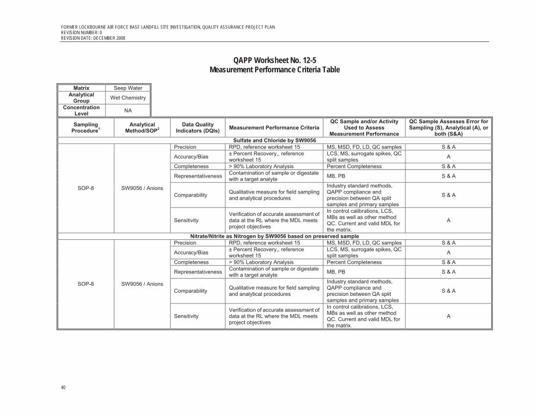
FORMER LOCKBOURNE AIR FORCE BASE LANDFILL SITE INVESTIGATION, QUALITY ASSURANCE PROJECT PLAN REVISION NUMBER: 0 REVISION DATE: DECEMBER 2008
40
QAPP Worksheet No. 12-5 Measurement Performance Criteria Table
Matrix Seep Water
Analytical Group Wet Chemistry
Concentration Level NA
Sampling Procedure1
Analytical Method/SOP2
Data Quality Indicators (DQIs) Measurement Performance Criteria
QC Sample and/or Activity Used to Assess
Measurement Performance
QC Sample Assesses Error for Sampling (S), Analytical (A), or
both (S&A) Sulfate and Chloride by SW9056
Precision RPD, reference worksheet 15 MS, MSD, FD, LD, QC samples S & A
Accuracy/Bias ± Percent Recovery,, reference worksheet 15
LCS, MS, surrogate spikes, QC split samples A
Completeness > 90% Laboratory Analysis Percent Completeness S & A
Representativeness Contamination of sample or digestate with a target analyte MB, PB S & A
Comparability Qualitative measure for field sampling and analytical procedures
Industry standard methods, QAPP compliance and precision between QA split samples and primary samples
S & A SOP-8 SW9056 / Anions
Sensitivity Verification of accurate assessment of data at the RL where the MDL meets project objectives
In control calibrations, LCS, MBs as well as other method QC. Current and valid MDL for the matrix.
A
Nitrate/Nitrite as Nitrogen by SW9056 based on preserved sample Precision RPD, reference worksheet 15 MS, MSD, FD, LD, QC samples S & A
Accuracy/Bias ± Percent Recovery,, reference worksheet 15
LCS, MS, surrogate spikes, QC split samples A
Completeness > 90% Laboratory Analysis Percent Completeness S & A
Representativeness Contamination of sample or digestate with a target analyte MB, PB S & A
Comparability Qualitative measure for field sampling and analytical procedures
Industry standard methods, QAPP compliance and precision between QA split samples and primary samples
S & A SOP-8 SW9056 / Anions
Sensitivity Verification of accurate assessment of data at the RL where the MDL meets project objectives
In control calibrations, LCS, MBs as well as other method QC. Current and valid MDL for the matrix.
A
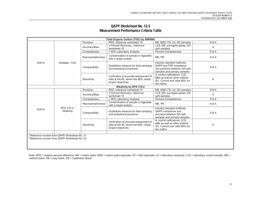
FORMER LOCKBOURNE AIR FORCE BASE LANDFILL SITE INVESTIGATION, QUALITY ASSURANCE PROJECT PLAN REVISION NUMBER: 0
REVISION DATE: DECEMBER 2008
41
QAPP Worksheet No. 12-5 Measurement Performance Criteria Table
Total Organic Carbon (TOC) by SW9060
Precision RPD, reference worksheet 15 MS, MSD, FD, LD, QC samples S & A
Accuracy/Bias ± Percent Recovery,, reference worksheet 15
LCS, MS, surrogate spikes, QC split samples A
Completeness > 90% Laboratory Analysis Percent Completeness S & A
Representativeness Contamination of sample or digestate with a target analyte MB, PB S & A
Comparability Qualitative measure for field sampling and analytical procedures
Industry standard methods, QAPP and FSP compliance and precision between QA split samples and primary samples
S & A SOP-8 SW9060 / TOC
Sensitivity Verification of accurate assessment of data at the RL where the MDL meets project objectives
In control calibrations, LCS, MBs as well as other method QC. Current and valid MDL for the matrix.
A
Alkalinity by EPA 310.2 Precision RPD, reference worksheet 15 MS, MSD, FD, LD, QC samples S & A
Accuracy/Bias ± Percent Recovery, reference worksheet 15
LCS, MS, surrogate spikes, QC split samples A
Completeness > 90% Laboratory Analysis Percent Completeness S & A
Representativeness Contamination of sample or digestate with a target analyte MB, PB S & A
Comparability Qualitative measure for field sampling and analytical procedures
Industry standard methods, QAPP compliance and precision between QA split samples and primary samples
S & A SOP-8 EPA 310.2 /
Alkalinity
Sensitivity Verification of accurate assessment of data at the RL where the MDL meets project objectives
In control calibrations, LCS, MBs as well as other method QC. Current and valid MDL for the matrix.
A
1Reference number from QAPP Worksheet No. 21. 2Reference number from QAPP Worksheet No. 23 Note: RPD = relative percent difference; MS = matrix spike; MSD = matrix spike duplicate; FD = field duplicate; LD = laboratory duplicate; LCS = laboratory control sample; MB = method blank; PB = prep blank; CB = Calibration Blank

FORMER LOCKBOURNE AIR FORCE BASE LANDFILL SITE INVESTIGATION, QUALITY ASSURANCE PROJECT PLAN REVISION NUMBER: 0 REVISION DATE: DECEMBER 2008
42
QAPP Worksheet No. 13 (UFP-QAPP Manual Section 2.7)
Secondary Data Criteria and Limitations Table
Identify all secondary data and information that will be used for the project and their originating sources. Specify how the secondary data will be used and the limitations on their use.
Worksheet Not Applicable (State Reason)
QAPP Worksheet No. 13
(UFP-QAPP Manual Section 2.7) Secondary Data Criteria and Limitations Table
Secondary Data
Data Source (Originating Organization, Report Title,
and Date)
Data Generator(s) (Originating Org., Data
Types, Data Generation/ Collection Dates) How Data Will Be Used
Limitations on Data Use
RI Report soil data Ellis Environmental Group (EEG). 2007. Remedial Investigation Report: Former Lockbourne Air Force Base Landfill. May. EEG Inc.
Historical soil data define the limits of the RI Addendum soil excavations. The RI report historical data also identify seep sample locations.
None for the current intended project objectives.
Phase II Report and data
Program Management Company (PMC), 2000. Phase II Site Investigation Report, Former Lockbourne AFB Landfill, Lockbourne, OH.
PMC Inc.
Historical soil data define the limits of the RI Addendum soil excavations. The RI report historical data also identify seep sample locations.
None for the current intended project objectives.
Phase I Report and data
Law Engineering and Environmental Services (Law). 1995. Final Site Investigation for Site Investigation –, Former Lockbourne Air Force Base Landfill, Rickenbacker Port Authority, Lockbourne, Ohio. November.
Law Inc. Historical soil data define the limits of the RI Addendum soil excavations.
None for the current intended project objectives.
Site Investigation Report and data
Engineering Science, Inc. 1992. Final Site Investigation Report, Rickenbacker Air National Guard Base, Columbus, Ohio. May 1992.
Engineering Science, Inc. Historical soil data define the limits of the RI Addendum soil excavations.
None for the current intended project objectives.

FORMER LOCKBOURNE AIR FORCE BASE LANDFILL SITE INVESTIGATION, QUALITY ASSURANCE PROJECT PLAN REVISION NUMBER: 0
REVISION DATE: DECEMBER 2008
43
QAPP Worksheet No. 14(UFP-QAPP Manual Section 2.8.1)
Summary of Project Tasks
Provide a brief overview of the listed project activities.
Worksheet Not Applicable (State Reason)
QAPP Worksheet No. 14(UFP-QAPP Manual Section 2.8.1)
Summary of Project Tasks
Summary of Project Tasks Sampling Tasks:
The following list represents the types of samples to be collected during the course of field activities that will be performed at off site laboratories. Six seep water samples plus the associated QA/QC samples will be collected. Worksheet 15 provides lists of compounds for each method to be analyzed and Worksheet 17 provides descriptions of sampling procedures.
� VOC � SVOC � Dioxin/Furans � Total metals � Dissolved metals (MNA only) � Nitrate/nitrite as nitrogen � Sulfate � Chloride � Alkalinity � Methane, ethane, and ethene � Total organic carbon
Soil gas samples analyzed for methane will be collected and analyzed in the field real-time and considered to be screening data only.
Analysis Tasks:
Offsite Laboratory Analyses:
Laboratory analysis will be based on the requirements of the QAPP and be compliant with the DoD QSM (latest version); and the LQSMS. Laboratory specific, method compliant SOPs are referenced in Worksheet 23.
Table 15-1 (worksheet 15) provides lists of compounds for each method to be analyzed. Also in Table 15-1 are project specific reporting limits (RL), laboratory specific method detection limits (MDL), upper and lower control limits for precision and accuracy as well as project-specific screening level objectives based on the EPA Region 9 Tap Water PRGs. For comparative purposes, the federal drinking water screening goals are listed in Table 15-1 as
FORMER LOCKBOURNE AIR FORCE BASE LANDFILL SITE INVESTIGATION, QUALITY ASSURANCE PROJECT PLAN REVISION NUMBER: 0 REVISION DATE: DECEMBER 2008
44
QAPP Worksheet No. 14(UFP-QAPP Manual Section 2.8.1)
Summary of Project Tasks well. The methods selected are the most sensitive available from commonly used industry standard SW-846 methods available today. However, there are some of the EPA Region 9 Tap Water PRGs that can not be met, that is, the PRG is lower than that of the laboratory specific MDL or RL. In this case, the final sample-specific MDL reported by the laboratory will be the lowest possible detection level achievable and will represent the level used to verify against the screening objectives.
Table 15-1A shows a target analyte list (TAL) based on a site-specific list of COPCs that were developed from available historical data after the completion of risk assessment activities. The COPCs are specific to the east or west ditches as well as for surface water and groundwater. Of the project specific COPCs, arsenic, trichloroethene can not be analyzed at concentrations low enough to meet the EPA Region 9 Tap Water PRG. Dibenzo(a,h)anthracene and benzo(a)pyrene will meet the EPA Region 9 Tap Water PRG when using the MDL and only if samples can be analyzed without complications such as matrix related interference. In addition, the breakdown product compounds to trichloroethene were added to the COPC list because of the possibility of trichloroethene breakdown; however, these compounds have not been documented to be actual COPCs.
Soil Gas Field Analysis of Methane:
Field analysis of soil gas for methane will consist of portable infrared detector (LandTec GEM 500 or equivalent) readings that will be conducted in accordance with Field SOP 6 Landfill Gas Probe Monitoring and Installation (Former Lockbourne AFB Landfill Site Investigation Work Plan CH2M HILL, August 2008, Appendix C). Calibration of the meter will be checked each day of testing in accordance with SOP 6.
Quality Control Tasks:
Field and Lab QC samples are specified in Worksheet 20. All field records generated in the field will undergo a review daily by a peer or field team leader. Laboratory analytical data will undergo internal reviews and validation as defined below in this worksheet. All reports generated by CH2M HILL will undergo senior-level reviews prior to release.
Secondary Data:
Reports and analytical data associated with prior investigations as defined in Worksheet 13.
Data Management Tasks:
Both hard copy and electronic data deliverables will be tracked, stored, handled, and managed. Data collected from field observations, laboratory and location information will be stored in the project database management system (DBMS). The DBMS will be used to perform sample tracking, storage of electronic data, validation of chemical data by the chemist, querying data for analysis, final data tables and available for any visualization required to support the project team. The following represent the summary of tasks.

FORMER LOCKBOURNE AIR FORCE BASE LANDFILL SITE INVESTIGATION, QUALITY ASSURANCE PROJECT PLAN REVISION NUMBER: 0
REVISION DATE: DECEMBER 2008
45
QAPP Worksheet No. 14(UFP-QAPP Manual Section 2.8.1)
Summary of Project Tasks
� Project Planning Support – generation of bottle labels and sampling worksheets
� Sample Tracking – From field to laboratory, laboratory to database and from database to report outputs and ultimately archival.
� Data Loading and QC – Loading of laboratory electronic data to DBMS (from ADR output) and QC of deliverables versus DBMS valid values, etc.
� Data Validation – The data validation will be completed by a third party contractor and reviewed by the PC. Results from the data validation will be loaded into the DBMS for internal project use. Data validation qualifiers will be directly applied to the electronic data and ultimately senior review of data validation. Please refer to the data validation section below for additional details.
� Data Reporting – The DBMS will be used to support all reporting functions from ad-hoc queries used in data analysis, formal reporting and any required data visualization efforts.
� Federal/State Deliverables – The data will be exported from the DBMS in formats that the USACE requires.
� Data Archival – The archival and storage of all hard copy and electronic deliverables.
Documentation and Records:
Field logs, field forms, chains-of-custody, correspondence, analytical data and project reports will be maintained in electronic format (PDF) at the CH2M HILL Dayton office.
Data Packages
Laboratory data packages will meet the requirements as described in Worksheet #11.
Assessment/Audit Tasks:
Audits of field staff compliance with project SOPs are not planned; however, records of field generated data will undergo a daily review by a peer or the field team leader for accuracy and compliance with project requirements. Audits of laboratory compliance with laboratory SOPs will be performed on a periodic basis as determined by the laboratory QA manager. In addition laboratory data will be audited as part of the data validation process as defined by this QAPP. CH2M HILL may audit the laboratory on site at any time based on need determined by the CH2M HILL project chemist. QA split samples will be sent to a laboratory other than the primary laboratory at a rate of 5 percent of all samples.
CT Laboratories (the primary laboratory) and Empirical Laboratories (QA split sample laboratory) will maintain current requirements for certification required by the state of Ohio and also carry current certification from the NELAP. CT Laboratories and Empirical Laboratories will also complete all required self-declaration documentation to the
FORMER LOCKBOURNE AIR FORCE BASE LANDFILL SITE INVESTIGATION, QUALITY ASSURANCE PROJECT PLAN REVISION NUMBER: 0 REVISION DATE: DECEMBER 2008
46
QAPP Worksheet No. 14(UFP-QAPP Manual Section 2.8.1)
Summary of Project Tasks satisfaction of the USACE Louisville District.
Data Validation:
Laboratory analytical data will be validated by Laboratory Data Consultants (LDC) Inc. staff experienced in the analysis and review of data from environmental matrices as follows.
All samples (100 percent) analyzed by the primary laboratory will be validated in accordance with the latest version of the DoD QSM and the LQSMS. Validation will consist of EPA Level IV data review. QA split laboratory sample results will not be validated; however, they will be evaluated for precision in comparison with the primary laboratory data. Significant errors noted during the data validation review may determine a need for corrective action based on recommendation of the project chemist and with concurrence of the USACE. Data validation shall include but may not be limited to the following parameters.
� Data completeness � Holding time � Instrument calibration, initial and continuing � Laboratory control samples � Method blanks � Surrogate spikes � Matrix spikes and matrix spike duplicates � Laboratory and field duplicates � Sample results verification
A data validation report will be provided at the end of the project to summarize the results of the data validation findings and to present conclusions regarding the usability of the data for project objectives. The data validation report will be included as an appendix to the overall project report. The data validation report will assess the accuracy, precision, representativeness, comparability, and completeness of the data generated. The report will focus on out of control data results and present a table of non-compliant results that exceeded some QC requirement.
Data Review Tasks:
Soil Gas Field Data:
All field measurements and or field log information will be entered into field log books and reviewed daily by the field team leader or designee. The designee may be by a qualified field geologists, engineers, environmental scientists, and/or technicians. Field generated information may include field log books, GEM calibrations and readings, waste management records and/or manifests, survey data, GIS data, sample chains of custody, shipping documents, sampling observations, sample labels and other miscellaneous field observations.

FORMER LOCKBOURNE AIR FORCE BASE LANDFILL SITE INVESTIGATION, QUALITY ASSURANCE PROJECT PLAN REVISION NUMBER: 0
REVISION DATE: DECEMBER 2008
47
QAPP Worksheet No. 14(UFP-QAPP Manual Section 2.8.1)
Summary of Project Tasks Offsite Laboratory Data:
The data validation process defined above is a separate task from that of internal laboratory data review tasks. Internal laboratory data review will entail several phases. First, the laboratory will perform internal reviews where all analytical data generated by the laboratory shall be verified before submittal to the CH2M HILL. This internal data review process, which is multi-tiered, shall include all aspects of data generation, reduction, and quality control assessment. In each laboratory analytical section, the analyst performing the tests shall review 100 percent of the definitive data. After the analyst’s review has been completed, 100 percent of the data shall be reviewed independently by a senior analyst or by the supervisor of the respective analytical section using the same criteria. The laboratory QA section shall perform a 100 percent review of 10 percent of the completed data packages, and the laboratory project representative shall complete a final review on all the completed data packages. Non-conformance reports (NCR) will be required for any errors noted. In all cases, an NCR shall be issued with the name of the individual reporting the issue, a description of the noncompliance issue, the corrective action taken, the date the issue was discovered, and the affected project samples. All employees are responsible for reporting the nonconformance. The appropriate supervisor is responsible for assuring that the corrective actions are taken.
Once the samples reach the laboratory, they shall be checked against information on the COC form for anomalies. The condition, temperature, and appropriate preservation of samples shall be checked and documented on the COC form. Checking an aliquot of the sample using pH paper is an acceptable procedure, except for VOCs where an additional sample is required to check preservation. The occurrence of any anomalies in the received samples and their resolution shall be documented in laboratory records. All sample information shall then be entered into a tracking system, and unique analytical sample identifiers shall be assigned. A copy of this information shall be reviewed by the laboratory for accuracy.
Once sample login is completed, a copy of the COC and sample condition of receipt details must be sent to the CH2M HILL project chemist by e-mail. This is expected to be completed within 24 hours of sample receipt. In addition, the laboratory must submit weekly a status report to the CH2M HILL project chemist to define each sample delivery group and delivery schedule.

FORMER LOCKBOURNE AIR FORCE BASE LANDFILL SITE INVESTIGATION, QUALITY ASSURANCE PROJECT PLAN REVISION NUMBER: 0 REVISION DATE: DECEMBER 2008
48
QAPP Worksheet No. 15 (UFP-QAPP Manual Section 2.8.1)
Reference Limits and Evaluation Table
Complete this worksheet for each matrix, analytical group, and concentration level. Identify the target analytes/contaminants of concern and project-required action limits. Next, determine the quantitation limits (QL) that must be met to achieve the project quality objectives. Finally, list the published and achievable detection and QLs for each analyte.
Worksheet Not Applicable (State Reason)
QAPP Worksheet No. 15 Table 15-1(UFP-QAPP Manual Section 2.8.1)
Reference Limits and Evaluation Table
EPA Region IX PRGs for Tap
Water Federal Drinking Water Standards Site Specific Site Specific Percent Recovery
Method Constituent CAS # Units Tap
Water MCLs SMCLs
SeepBackground
Concentrations East and West
Ditch
Groundwater Background
Concentrations Upper Water Bearing Zone
MostStringent Screening
Level1 Laboratory
RL
DoesRL
ExceedScreening
Level? Laboratory
MDL
DoesMDL
ExceedScreening
Level? Surrogate Lower Limit
UpperLimit RPD
EPA 310.2 Alkalinity Alkalinity mg/L -- -- -- -- -- -- 22 NO 7.0 NO NO 90 110 20 SW9056 Nitrate-Nitrite as Nitrogen NITRATE-NITRITE mg/L -- -- -- -- -- -- 0.42 NO 0.12 NO NO 80 120 20 RSK-175 Ethane 74-84-0 ug/L -- -- -- -- -- -- 1.4 NO 0.4 NO NO 70 130 20 RSK-175 Ethene 74-85-1 ug/L -- -- -- -- -- -- 1.7 NO 0.5 NO NO 70 130 20 RSK-175 Methane 74-82-8 ug/L -- -- -- -- -- -- 0.83 NO 0.25 NO NO 70 130 20 SW6010B Aluminum 7429-90-5 mg/L 36 -- 0.050 16.6 16.6 0.050 0.016 NO 0.005 NO NO 80 120 20 SW6010B Cadmium 7440-43-9 mg/L 0.018 0.0050 -- 0.007 -- 0.0050 0.0011 NO 0.0003 NO NO 80 120 20 SW6010B Cobalt 7440-48-4 mg/L 0.73 -- -- 0.04 0.04 0.7300 0.0028 NO 0.0008 NO NO 80 120 20 SW6010B Copper 7440-50-8 mg/L 1.5 1.3 1.0 0.068 0.068 1.0000 0.004 NO 0.0012 NO NO 80 120 20 SW6010B Iron 7439-89-6 mg/L 11 -- 0.30 3.85 3.85 0.30 0.027 NO 0.008 NO NO 80 120 20 SW6010B Lead 7439-92-1 mg/L -- 0.015 -- 0.033 0.033 0.0150 0.0046 NO 0.0014 NO NO 80 120 20 SW6010B Manganese 7439-96-5 mg/L 0.88 -- 0.050 0.877 0.877 0.050 0.014 NO 0.004 NO NO 80 120 20 SW6010B Selenium 7782-49-2 mg/L 0.18 0.050 -- 0.0165 0.0165 0.0500 0.014 NO 0.004 NO NO 80 120 20 SW6010B Zinc 7440-66-6 mg/L 11 -- 5.0 0.3 0.3 5.000 0.0063 NO 0.0019 NO NO 80 120 20 SW7060A Arsenic 7440-38-2 mg/L 0.00004 0.010 -- 0.00927 0.00927 0.00004 0.0026 YES 0.0008 YES NO 80 120 20 SW8260B 1,1-DCE 75-35-4 ug/L 339 7.0 -- -- -- 7.0 1.3 NO 0.4 NO NO 70 135 20 SW8260B Cis-1,2-DCE 156-59-2 ug/L 61 70 -- -- -- 61 1.2 NO 0.4 NO NO 70 125 20 SW8260B Methylene chloride 75-09-2 ug/L 4.3 5.0 -- -- -- 4.3 2 NO 0.5 NO NO 55 140 20 SW8260B TCE 79-01-6 ug/L 0.028 5.0 -- -- -- 0.028 1 YES 0.15 YES NO 75 125 20 SW8260B trans-1,2-DCE 156-60-5 ug/L 122 100 -- -- -- 100 1.8 NO 0.5 NO NO 60 140 20 SW8260B Vinyl chloride 75-01-4 ug/L 0.020 2.0 -- -- -- 0.020 1 YES 0.15 YES NO 50 145 20 SW8260B 1,2-Dichloroethane-d4 1868-53-7 % -- -- -- -- -- -- -- -- -- -- YES 70 120 -- SW8260B Toluene-d8 460-00-4 % -- -- -- -- -- -- -- -- -- -- YES 85 120 -- SW8260B 4-Bromofluorobenzene 2037-26-5 % -- -- -- -- -- -- -- -- -- -- YES 75 120 -- SW8260B 1,2-Dichlorobenzene-d4 17060-07-0 % -- -- -- -- -- -- -- -- -- -- YES 71 123 -- SW8270C Bis (2-ethylhexyl) phthalate 117-81-7 ug/L 4.8 6.0 -- -- -- 4.8 1 NO 0.23 NO NO 40 125 20 SW8270-SIM Benzo (a) anthracene 56-55-3 ug/L 0.092 -- -- -- -- 0.092 0.026 NO 0.008 NO NO 43 138 30 SW8270-SIM Benzo (a) pyrene 50-32-8 ug/L 0.0092 0.20 -- -- -- 0.0092 0.02 YES 0.006 NO NO 38 144 30 SW8270-SIM Benzo (b) fluoranthene 205-99-2 ug/L 0.092 -- -- -- -- 0.092 0.03 NO 0.009 NO NO 31 146 30 SW8270-SIM Dibenzo (a,h) anthracene 53-70-3 ug/L 0.0092 -- -- -- -- 0.0092 0.029 YES 0.009 NO NO 38 130 30 SW8270-SIM Indeno (1,2,3-c,d) pyrene 193-39-5 ug/L 0.092 -- -- -- -- 0.092 0.035 NO 0.011 NO NO 37 130 30

FORMER LOCKBOURNE AIR FORCE BASE LANDFILL SITE INVESTIGATION, QUALITY ASSURANCE PROJECT PLAN REVISION NUMBER: 0
REVISION DATE: DECEMBER 2008
49
QAPP Worksheet No. 15 Table 15-1(UFP-QAPP Manual Section 2.8.1)
Reference Limits and Evaluation Table
EPA Region IX PRGs for Tap
Water Federal Drinking Water Standards Site Specific Site Specific Percent Recovery
Method Constituent CAS # Units Tap
Water MCLs SMCLs
SeepBackground
Concentrations East and West
Ditch
Groundwater Background
Concentrations Upper Water Bearing Zone
MostStringent Screening
Level1 Laboratory
RL
DoesRL
ExceedScreening
Level? Laboratory
MDL
DoesMDL
ExceedScreening
Level? Surrogate Lower Limit
UpperLimit RPD
SW8270-SIM Terphenyl-d14 1718-51-0 % -- -- -- -- -- -- -- -- -- -- YES 50 150 -- SW8290 1,2,3,4,6,7,8-Heptachlorodibenzo 67562-39-4 ug/L -- -- -- -- -- -- 0.00005 NO 0.000025 NO NO 50 120 20 SW8290 1,2,3,4,6,7,8-Heptachlorodibenzo- 35822-46-9 ug/L -- -- -- -- -- -- 0.00005 NO 0.000025 NO NO 50 120 30 SW8290 1,2,3,4,7,8,9-Heptachlorodibenzo 55673-89-7 ug/L -- -- -- -- -- -- 0.00005 NO 0.000025 NO NO 50 120 30 SW8290 1,2,3,4,7,8-Hexachlorodibenzo- 39227-28-6 ug/L -- -- -- -- -- -- 0.00005 NO 0.000025 NO NO 50 120 30 SW8290 1,2,3,4,7,8-Hexachlorodibenzofuran 70648-26-9 ug/L -- -- -- -- -- -- 0.00005 NO 0.000025 NO NO 50 120 30 SW8290 1,2,3,6,7,8-Hexachlorodibenzo- 57653-85-7 ug/L -- -- -- -- -- -- 0.00005 NO 0.000025 NO NO 50 120 30 SW8290 1,2,3,6,7,8-Hexachlorodibenzofuran 57117-44-9 ug/L -- -- -- -- -- -- 0.00005 NO 0.000025 NO NO 50 120 30 SW8290 1,2,3,7,8,9-Hexachlorodibenzo- 19408-74-3 ug/L -- -- -- -- -- -- 0.00005 NO 0.000025 NO NO 50 120 30 SW8290 1,2,3,7,8,9-Hexachlorodibenzofuran 72918-21-9 ug/L -- -- -- -- -- -- 0.00005 NO 0.000025 NO NO 50 120 30 SW8290 1,2,3,7,8-Pentachlorodibenzofuran 57117-41-6 ug/L -- -- -- -- -- -- 0.00005 NO 0.000025 NO NO 50 120 30 SW8290 1,2,3,7,8-Pentachlorodibenzo-p 40321-76-4 ug/L -- -- -- -- -- -- 0.00005 NO 0.000025 NO NO 50 120 30 SW8290 2,3,4,6,7,8-Hexachlorodibenzofuran 60851-34-5 ug/L -- -- -- -- -- -- 0.00005 NO 0.000025 NO NO 50 120 30 SW8290 2,3,4,7,8-Pentachlorodibenzofuran 57117-31-4 ug/L -- -- -- -- -- -- 0.00005 NO 0.000025 NO NO 50 120 30 SW8290 2,3,7,8-Tetrachlorodibenzofuran 51207-31-9 ug/L -- -- -- -- -- -- 0.00001 NO 0.000005 NO NO 50 120 30 SW8290 2,3,7,8-Tetrachlorodibenzo-p-D 1746-01-6 ug/L 0.00045 -- -- -- -- 0.00045 0.00001 NO 0.000005 NO NO 50 120 30 SW8290 Octachlorodibenzofuran 39001-02-0 ug/L -- -- -- -- -- -- 0.0001 NO 0.00005 NO NO 50 120 30 SW8290 Octachlorodibenzo-p-Dioxin 3268-87-9 ug/L -- -- -- -- -- -- 0.0001 NO 0.00005 NO NO 50 120 30 SW9056 Chloride Chloride mg/L -- -- -- -- -- -- 3.3 NO 1.00 NO NO 80 120 20 SW9056 Sulfate Sulfate mg/L -- -- -- -- -- -- 3.4 NO 1.00 NO NO 80 120 20 SW9060 Total Organic Carbon TOC mg/L -- -- -- -- -- -- 2.8 NO 0.80 NO NO 85 113 20 Notes: Constituents with "%" units are surrogates and are not a part of the target analytes. mg/L = milligrams per liter ug/L = micrograms per liter RL = reporting limit MDL = method detection limit If shaded Gray, the expected MDL will exceed the most stringent screening objective 1 For water, most stringent of: U.S. EPA Region IX preliminary remediation goals (PRGs), Tap Water (October 2004) U.S. EPA Drinking Water Maximum Contaminant Levels (MCLs) and Secondary Maximum Contaminant Levels (SMCLs), 40 CFR 141, 142

FORMER LOCKBOURNE AIR FORCE BASE LANDFILL SITE INVESTIGATION, QUALITY ASSURANCE PROJECT PLAN REVISION NUMBER: 0 REVISION DATE: DECEMBER 2008
50
QAPP Worksheet No. 15 (UFP-QAPP Manual Section 2.8.1)
Reference Limits and Evaluation Table
Table 15-1A COPCs for Seeps, Surface Water and GroundwaterGroundwater Seeps Seeps Surface Water
COPCUWBZ East
DitchWestDitch
EastDitch
WestDitch
Aluminum X X
Arsenic X X
Cadmium X
Cobalt X
Copper X X
Iron X X X
Lead X X X
Manganese X
Nitrogen, NO2+NO3 X O
Selenium X
Zinc X
Benz(a)anthracene X
Benzo(a)pyrene X
Benzo(b)fluoranthene X
Dibenz(ah)anthracene X
Indeno(1,2,3-cd)pyrene X
Bis(2-ethyl hexyl)phthalate X
TCDD-TEQ X X X
Methylene chloride X X X
Trichloroethene X
Key: COPC = Compound of potential concern UWBZ = Upper water-bearing zone Notes:
X = This constituent is included as a COPC and evaluated further in the HRA because the maximum detected concentration exceeded a health-based soil screening level and background
O = No PRG was available for this constituent; therefore it was considered a COPC and evaluated further in the HRA.
FORMER LOCKBOURNE AIR FORCE BASE LANDFILL SITE INVESTIGATION, QUALITY ASSURANCE PROJECT PLAN REVISION NUMBER: 0
REVISION DATE: DECEMBER 2008
51
QAPP Worksheet No. 16(UFP-QAPP Manual Section 2.8.2) Project Schedule/Timeline Table
List all project activities as well as the QA assessments that will be performed during the course of the project. Include the anticipated start and completion dates.
Worksheet Not Applicable (State Reason)
As the project progresses, this schedule will be updated, as necessary. Refer to the Project schedule attached.

ID Task Name Duration Start Finish
1 TASK 1--Soil Gas Sampling 20 days Mon 1/5/09 Fri 1/30/09
2 Round 1 of Soil Gas Sampling 5 days Mon 1/5/09 Fri 1/9/09
3 Round 2 of Soil Gas Sampling 5 days Mon 1/26/09 Fri 1/30/09
4 TASK 2--Site Investigation (SI) Report 59 days Mon 2/16/09 Thu 5/7/09
5 Draft SI Report to USACE 11 days Mon 2/16/09 Mon 3/2/09
6 Draft Final SI Report to Ohio EPA 35 days Mon 3/9/09 Fri 4/24/09
7 Final SI Report to USACE 2 days Mon 4/27/09 Tue 4/28/09
8 Final SI Report to Ohio EPA 5 days Fri 5/1/09 Thu 5/7/09
9 TASK 3-- Draft Final Remedial Investigation (RI) Report 126 days? Tue 12/16/08 Tue 6/9/09
10 Draft Final RI Report to USACE 75 days? Tue 12/16/08 Mon 3/30/09
11 Draft Final RI Report to Ohio EPA 35 days Mon 4/6/09 Fri 5/22/09
12 Final RI Report to USACE 2 days Mon 6/1/09 Tue 6/2/09
13 Final RI Report to Ohio EPA 5 days Wed 6/3/09 Tue 6/9/09
14 TASK 4--Feasibility Study (FS) Report 122 days Mon 5/4/09 Tue 10/20/09
15 Draft FS Report to USACE 41 days Mon 5/4/09 Mon 6/29/09
16 Draft Final FS Report to Ohio EPA 35 days Mon 7/27/09 Fri 9/11/09
17 Final FS Report to USACE 2 days Thu 10/8/09 Fri 10/9/09
18 Final FS Report to Ohio EPA 5 days Wed 10/14/09 Tue 10/20/09
Nov Dec Jan Feb Mar Apr May Jun Jul Aug Sep Oct NovQtr 1, 2009 Qtr 2, 2009 Qtr 3, 2009 Qtr 4, 2009
Task
Split
Progress
Milestone
Summary
Project Summary
External Tasks
External Milestone
Deadline
LOCKBOURNE ALL TASKS (SI & RI/FS PROJECTS)
Page 1
Project: Lockbourne ALL Schedule 12Date: Tue 12/16/08

FORMER LOCKBOURNE AIR FORCE BASE LANDFILL SITE INVESTIGATION, QUALITY ASSURANCE PROJECT PLAN REVISION NUMBER: 0
REVISION DATE: DECEMBER 2008
53
QAPP Worksheet No. 17-1 (UFP-QAPP Section 3.1.1)
Sampling Design and Rationale
Describe the project sampling approach. Provide the rationale for selecting sample locations and matrices for each analytical group and concentration level.
Worksheet Not Applicable (State Reason)
QAPP Worksheet No. 17-1 (UFP-QAPP Section 3.1.1)
Sampling Design and Rationale Seep Sampling
Describe and provide a rationale for choosing the sampling approach:
CH2M HILL will collect seep water samples from approximately six locations, with exact coordinates to be determined, along the perimeter of the “heavily used” landfill area. Figure 2-3 of the Former Lockbourne AFB Landfill Site Investigation Work Plan CH2M HILL, August 2008 depicts the locations that have been sampled historically during the Site and Remedial Investigations. Attempts will be made to locate these seeps or others that may be present during the fieldwork. The temporary probes will be installed by manually driving a 1-inch diameter hollow, steel rod approximately 2 feet horizontally into the embankment at the location of a seep. The rod will be removed and the polyvinyl chloride (PVC) casing and screen will be inserted into the boring. If the boring collapses prior to PVC insertion, the PVC will be manually driven (using caution) into the collapsed boring. These are expected to be driven horizontally along the fairly steep embankment between the landfill and the drainage channel on the west. A water sample will be collected through use of a peristaltic pump sampling system through sampling of flow coming off driven (horizontal) piezometers. The samples will be analyzed for target analytes as defined in Table 15 (worksheet 15). Seep water sampling will be conducted in accordance with Field SOP-8 Seep Water Sampling.
Seep water samples will be analyzed on a standard turnaround time. Field QC sample collection is summarized in Worksheet 20, and each field QC sample type is defined in Worksheets 28 of this QAPP. One matrix spike/matrix spike duplicate (MS/MSD), one blind field duplicate, and one field blank will be collected and analyzed for the same suite as the standard seep samples.
Describe the sampling design and rationale in terms of what matrices will be sampled, what analytical groups will and at what concentration levels, the sampling locations, the number of samples to be taken, and the sampling frequency:

FORMER LOCKBOURNE AIR FORCE BASE LANDFILL SITE INVESTIGATION, QUALITY ASSURANCE PROJECT PLAN REVISION NUMBER: 0 REVISION DATE: DECEMBER 2008
54
QAPP Worksheet No. 17-1 (UFP-QAPP Section 3.1.1)
Sampling Design and Rationale Seep samples will be collected from an anticipated six seep locations along the slope of the former landfill area designated as “heavily used” in accordance with methods described in the Former Lockbourne AFB Landfill Site Investigation Work Plan CH2M HILL, August 2008 and Field SOP-8 Seep Water Sampling.
Seep samples will be collected and analyzed for the contaminants listed in Worksheet 15.
Locations of samples shall be marked in the field and documented in the field and on any applicable report figures.
Additional sample information can be found in Worksheet No. 18.
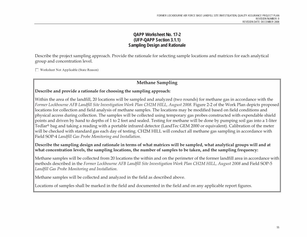
FORMER LOCKBOURNE AIR FORCE BASE LANDFILL SITE INVESTIGATION, QUALITY ASSURANCE PROJECT PLAN REVISION NUMBER: 0
REVISION DATE: DECEMBER 2008
55
QAPP Worksheet No. 17-2 (UFP-QAPP Section 3.1.1)
Sampling Design and Rationale
Describe the project sampling approach. Provide the rationale for selecting sample locations and matrices for each analytical group and concentration level.
Worksheet Not Applicable (State Reason)
Methane Sampling
Describe and provide a rationale for choosing the sampling approach:
Within the area of the landfill, 20 locations will be sampled and analyzed (two rounds) for methane gas in accordance with the Former Lockbourne AFB Landfill Site Investigation Work Plan CH2M HILL, August 2008. Figure 2-2 of the Work Plan depicts proposed locations for collection and field analysis of methane samples. The locations may be modified based on field conditions and physical access during collection. The samples will be collected using temporary gas probes constructed with expendable shield points and driven by hand to depths of 1 to 2 feet and sealed. Testing for methane will be done by pumping soil gas into a 1-liter Tedlar® bag and taking a reading with a portable infrared detector (LandTec GEM 2000 or equivalent). Calibration of the meter will be checked with standard gas each day of testing. CH2M HILL will conduct all methane gas sampling in accordance with Field SOP-4 Landfill Gas Probe Monitoring and Installation.
Describe the sampling design and rationale in terms of what matrices will be sampled, what analytical groups will and at what concentration levels, the sampling locations, the number of samples to be taken, and the sampling frequency:
Methane samples will be collected from 20 locations the within and on the perimeter of the former landfill area in accordance with methods described in the Former Lockbourne AFB Landfill Site Investigation Work Plan CH2M HILL, August 2008 and Field SOP-5 Landfill Gas Probe Monitoring and Installation.
Methane samples will be collected and analyzed in the field as described above.
Locations of samples shall be marked in the field and documented in the field and on any applicable report figures.

FORMER LOCKBOURNE AIR FORCE BASE LANDFILL SITE INVESTIGATION, QUALITY ASSURANCE PROJECT PLAN REVISION NUMBER: 0 REVISION DATE: DECEMBER 2008
56
QAPP Worksheet No. 18 (UFP-QAPP Manual Section 3.1.1)
Sampling Locations and Methods/SOP Requirements Table
List all site locations that will be sampled and include sample/ID number, if available. (Provide a range of sampling locations or ID numbers if a site has a large number.) Specify matrix and, if applicable, depth at which samples will be taken. Only a short reference for the sampling location rationale is necessary for the table. The text of the QAPP should clearly identify the detailed rationale associated with each reference. Complete all required information, using additional worksheets if necessary.
Worksheet Not Applicable (State Reason)
Remedial Design Sampling
Location/ID Number Matrix
Depth (ft bgs) Analytical Group 1
ConcentrationLevel
Number of Samples (identify field
duplicates
Sampling SOP
Reference Rationale for Sampling Location VOCs
Dioxin/furans
SVOCs
Total Metals
Dissolved metals for MNA
Nitrate/nitrite as Nitrogen
Sulfate and chloride Alkalinity
Total organic carbon
Seep 1, 2, 3, 4, 5 and 6 (Exact nomenclature/ Field IDs to be determined in the field)
Seep Water NA
Methane, ethane, ethene
NA 6 plus one duplicate SOP 8 Identify the presence or absence of
contaminated water exiting from below ground as seepage from the landfill
Field analysis of Methane (Exact nomenclature/ Field IDs to be determined in the field)
Soil Gas
To be Determined by field conditions
Methane
NA
20 (for two rounds)
SOP 6
Identify the presence or absence of methane gas being generate within the landfill
1 Please refer to Worksheet 15 for the list of target analytes.

FORMER LOCKBOURNE AIR FORCE BASE LANDFILL SITE INVESTIGATION, QUALITY ASSURANCE PROJECT PLAN REVISION NUMBER: 0
REVISION DATE: DECEMBER 2008
57
QAPP Worksheet No. 19(UFP-QAPP Manual Section 3.1.1)
Analytical SOP Requirements Table
For each matrix, analytical group, and concentration level, list the analytical and preparation method and SOP and associated sample volume, container specifications, preservation requirements, and maximum holding time.
Worksheet Not Applicable (State Reason)
Analytical SOP Requirements Table
Matrix Analytical Group Concentration
Level
Analytical and Preparation
Method/SOP Reference1SampleVolume
Containers (number, size, and
type)
Preservation Requirements (chemical, temperature, light
protected)
Maximum Holding Time (preparation/
analysis) Water Metals NA SW6010B/SW7060A/Dis
solved or total metals prep for ICP, Arsenic prep, Metals by GFAA, Metals by ICP
100 ml 1 liter polyethylene
pH < 2 with nitric acid; 4 +/- 2 degrees Celsius
28days from date of collection for Hg, others, 180 days
Water SVOCs and PAHs NA SW8270CSIM/Semivolatiles
1 liter 2 1-liter amber glass
4 +/- 2 degrees Celsius
7 days from date of collection to extraction and 40 days from extraction to analysis
Water Dioxins/furans NA SW8290/ Dioxins Furans 1 liter 2 1-liter amber glass
4 +/- 2 degrees Celsius
14 days from date of collection to extraction and 40 days from extraction to analysis
Water VOCs NA SW8260B/ VOCs 3 40 ml vials 3 40 ml VOA vials
No headspace; pH < 2 with HCl; 4 +/- 2 degrees Celsius
14 days from data of collection
Water Alkalinity as CaCO3 NA EPA 310.2/Alkalinity 125 ml 250 ml polyethylene
4 +/- 2 degrees Celsius
14 days from date of collection
Water TOC NA SW9060/TOC 500 ml 1 liter polyethylene
4 +/- 2 degrees Celsius, HCL or H2SO4 to pH < 2
28 days from date of collection
Water Nitrate/nitrite as Nitrogen
NA SW9056/100-03-4 NO2-NO3
500 ml 1 liter polyethylene
4 +/- 2 degrees Celsius, H2SO4 to pH < 2
28 days from date of collection
Water Methane, ethane and ethene
NA RSK175/Dissolved Gases
3 40 ml vials 3 40 ml VOA vials
No headspace; pH < 2 with HCl; 4 +/- 2 degrees Celsius
14 days from data of collection
Water Sulfate and Chloride NA SW9056/Anions 50 ml 125 ml polyethylene
4 +/- 2 degrees Celsius
28 days from collection
1Specify the appropriate reference letter or number from the Analytical SOP References table (Worksheet No. 23).
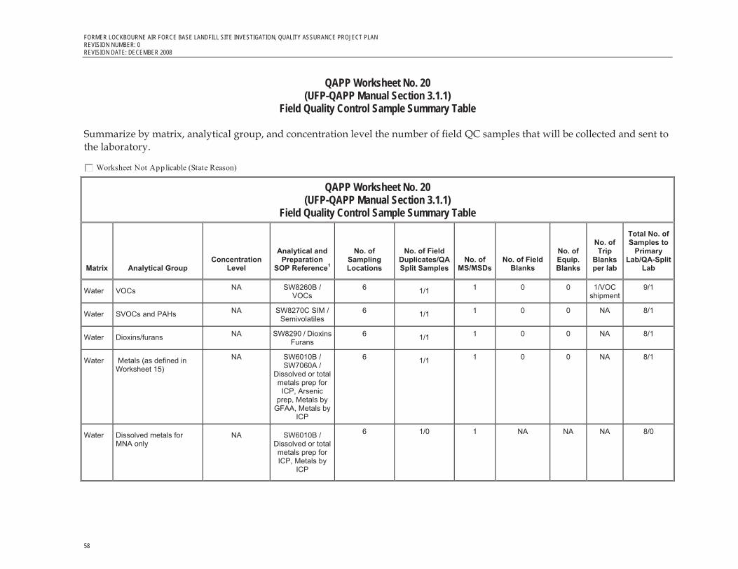
FORMER LOCKBOURNE AIR FORCE BASE LANDFILL SITE INVESTIGATION, QUALITY ASSURANCE PROJECT PLAN REVISION NUMBER: 0 REVISION DATE: DECEMBER 2008
58
QAPP Worksheet No. 20(UFP-QAPP Manual Section 3.1.1)
Field Quality Control Sample Summary Table
Summarize by matrix, analytical group, and concentration level the number of field QC samples that will be collected and sent to the laboratory.
Worksheet Not Applicable (State Reason)
QAPP Worksheet No. 20(UFP-QAPP Manual Section 3.1.1)
Field Quality Control Sample Summary Table
Matrix Analytical Group Concentration
Level
Analytical and Preparation
SOP Reference1
No. of Sampling Locations
No. of Field Duplicates/QA Split Samples
No. of MS/MSDs
No. of Field Blanks
No. of Equip.Blanks
No. of Trip
Blanksper lab
Total No. of Samples to
Primary Lab/QA-Split
Lab
Water VOCs NA SW8260B / VOCs
6 1/1 1 0 0 1/VOC shipment
9/1
Water SVOCs and PAHs NA SW8270C SIM / Semivolatiles
6 1/1 1 0 0 NA 8/1
Water Dioxins/furans NA SW8290 / Dioxins Furans
6 1/1 1 0 0 NA 8/1
Water Metals (as defined in Worksheet 15)
NA SW6010B / SW7060A /
Dissolved or total metals prep for ICP, Arsenic
prep, Metals by GFAA, Metals by
ICP
6 1/1 1 0 0 NA 8/1
Water Dissolved metals for MNA only
NA SW6010B / Dissolved or total metals prep for ICP, Metals by
ICP
6 1/0 1 NA NA NA 8/0

FORMER LOCKBOURNE AIR FORCE BASE LANDFILL SITE INVESTIGATION, QUALITY ASSURANCE PROJECT PLAN REVISION NUMBER: 0
REVISION DATE: DECEMBER 2008
59
QAPP Worksheet No. 20(UFP-QAPP Manual Section 3.1.1)
Field Quality Control Sample Summary Table
Matrix Analytical Group Concentration
Level
Analytical and Preparation
SOP Reference1
No. of Sampling Locations
No. of Field Duplicates/QA Split Samples
No. of MS/MSDs
No. of Field Blanks
No. of Equip.Blanks
No. of Trip
Blanksper lab
Total No. of Samples to
Primary Lab/QA-Split
Lab
Water Nitrate/nitrite as nitrogen for MNA
NA SW9056 / 100-03-4 NO2-NO3
6 1/0 1 NA NA NA 8/0
Water Sulfate and chloride for MNA
NA SW9056 / Anions 6 1/0 1 NA NA NA 8/0
Water Alkalinity for MNA NA EPA 310.2 / Alkalinity
6 1/0 1 NA NA NA 8/0
Water Methane, ethane and ethene for MNA
NA RSK175 / Dissolved Gasses
6 1/0 1 NA NA NA 8/0
Water Total organic carbon for MNA
NA SW9060 / TOC 6 1/0 1 NA NA NA 8/0
Soil gas
Methane NA Field Screening / SOP -6
20 2/0 0 NA NA NA 0
1Specify the appropriate reference letter or number from the Analytical SOP References table (Worksheet No. 23).
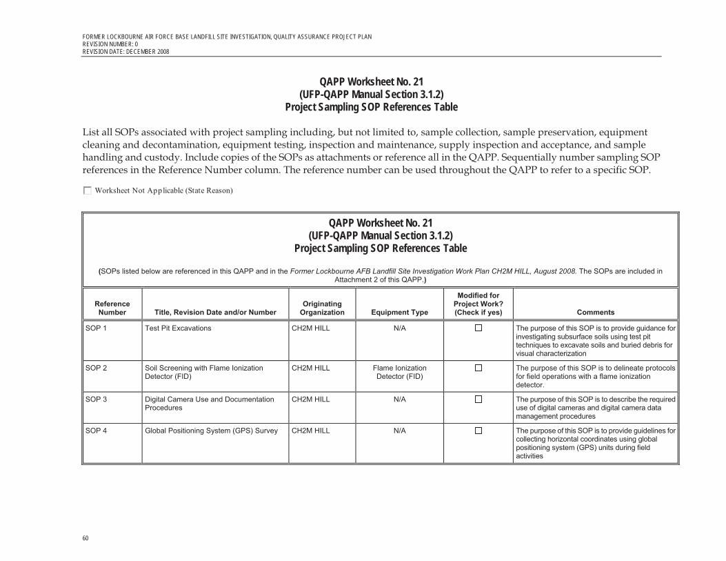
FORMER LOCKBOURNE AIR FORCE BASE LANDFILL SITE INVESTIGATION, QUALITY ASSURANCE PROJECT PLAN REVISION NUMBER: 0 REVISION DATE: DECEMBER 2008
60
QAPP Worksheet No. 21(UFP-QAPP Manual Section 3.1.2)
Project Sampling SOP References Table
List all SOPs associated with project sampling including, but not limited to, sample collection, sample preservation, equipment cleaning and decontamination, equipment testing, inspection and maintenance, supply inspection and acceptance, and sample handling and custody. Include copies of the SOPs as attachments or reference all in the QAPP. Sequentially number sampling SOP references in the Reference Number column. The reference number can be used throughout the QAPP to refer to a specific SOP.
Worksheet Not Applicable (State Reason)
QAPP Worksheet No. 21(UFP-QAPP Manual Section 3.1.2)
Project Sampling SOP References Table
(SOPs listed below are referenced in this QAPP and in the Former Lockbourne AFB Landfill Site Investigation Work Plan CH2M HILL, August 2008. The SOPs are included in Attachment 2 of this QAPP.)
Reference Number Title, Revision Date and/or Number
Originating Organization Equipment Type
Modified for Project Work? (Check if yes) Comments
SOP 1 Test Pit Excavations CH2M HILL N/A The purpose of this SOP is to provide guidance for investigating subsurface soils using test pit techniques to excavate soils and buried debris for visual characterization
SOP 2 Soil Screening with Flame Ionization Detector (FID)
CH2M HILL Flame Ionization Detector (FID)
The purpose of this SOP is to delineate protocols for field operations with a flame ionization detector.
SOP 3 Digital Camera Use and Documentation Procedures
CH2M HILL N/A The purpose of this SOP is to describe the required use of digital cameras and digital camera data management procedures
SOP 4 Global Positioning System (GPS) Survey CH2M HILL N/A The purpose of this SOP is to provide guidelines for collecting horizontal coordinates using global positioning system (GPS) units during field activities

FORMER LOCKBOURNE AIR FORCE BASE LANDFILL SITE INVESTIGATION, QUALITY ASSURANCE PROJECT PLAN REVISION NUMBER: 0
REVISION DATE: DECEMBER 2008
61
QAPP Worksheet No. 21(UFP-QAPP Manual Section 3.1.2)
Project Sampling SOP References Table
(SOPs listed below are referenced in this QAPP and in the Former Lockbourne AFB Landfill Site Investigation Work Plan CH2M HILL, August 2008. The SOPs are included in Attachment 2 of this QAPP.)
Reference Number Title, Revision Date and/or Number
Originating Organization Equipment Type
Modified for Project Work? (Check if yes) Comments
SOP 5 Temporary Soil Gas Probe Installation and Sampling
CH2M HILL N/A The purpose of this SOP is to provide general guidelines for the installation of shallow soil gas temporary sampling probes
SOP 6 Landfill Gas Probe Monitoring, GEM2000 Operation
CH2M HILL Portable infrared detector The purpose of this SOP is to delineate protocols for field operations with a combustible portable infrared monitor.
SOP 7 Landfill Gas Probe Monitoring CH2M HILL N/A The purpose of this SOP is to provide general guidelines for monitoring a landfill gas probe
SOP 8 Low Flow Seep Water Sampling CH2M HILL N/A The purpose of this SOP is to delineate protocols for the collection of water samples using a peristaltic pump.
SOP 9 Field Filtering Water Samples CH2M HILL N/A The purpose of this SOP is to provide technical guidance for filtering suspended solids in ground water samples which will be analyzed for metals.
SOP 10 Field Decontamination Procedures CH2M HILL N/A This SOP provides guidelines for decontamination groundwater investigation equipment, sampling equipment, and monitoring equipment used in potentially contaminated environments
SOP 11 Sample Handling, Chain of Custody and Shipping Procedures
CH2M HILL N/A The purpose of this SOP is to delineate protocols for the packing and shipping of samples to the laboratory for analysis and the use of the COC Form
SOP12 Field Documentation CH2M HILL N/A The purpose of this SOP is to delineate protocols for recording field survey and sampling information in a field logbook.

FORMER LOCKBOURNE AIR FORCE BASE LANDFILL SITE INVESTIGATION, QUALITY ASSURANCE PROJECT PLAN REVISION NUMBER: 0 REVISION DATE: DECEMBER 2008
62
QAPP Worksheet No. 22(UFP-QAPP Manual Section 3.1.2.4)
Field Equipment Calibration, Maintenance, Testing, and Inspection Table
Identify all field equipment and instruments (other than analytical instrumentation) that require calibration, maintenance, testing, or inspection and provide the SOP reference number for each type of equipment. In addition, document the frequency of activity, acceptance criteria, and corrective action requirements on the worksheet.
Worksheet Not Applicable (State Reason)
Field Equipment Calibration, Maintenance, Testing, and Inspection Table
FieldEquipment
Calibration Activity
Maintenance Activity
Testing Activity
Inspection Activity
Frequency Acceptance Criteria
Corrective Action
Responsible Person
SOP Reference1
Portable infrared detector (LandTec GEM 500 or equivalent) for methane analysis
Calibrate for methane and ambient gases using compressed gas cylinders
Charge batteries. Allow the batteries to totally discharge before recharging to prevent battery memory from occurring.
Evaluation of methane levels
NA Daily before use. Occasionally, as needed.
Check operations manual for acceptable range of calibrated probe.
If meter fails to calibrate, do not use this meter.
Field Team lead.
CH2M HILL SOP-6
Flame ionization detector (FID)
Calibrate for VOCs and ambient gases using compressed gas cylinders
Charge batteries. Allow the batteries to totally discharge before recharging to prevent battery memory from occurring.
Evaluation of VOC vapor levels
NA Daily before use. Occasionally, as needed.
Check operations manual for acceptable range of calibrated probe.
If meter fails to calibrate, do not use this meter.
Field Team lead CH2M HILL SOP-2
1Specify the appropriate reference letter or number from the Project Sampling SOP References table (Worksheet No. 21). NA – Not applicable.

FORMER LOCKBOURNE AIR FORCE BASE LANDFILL SITE INVESTIGATION, QUALITY ASSURANCE PROJECT PLAN REVISION NUMBER: 0
REVISION DATE: DECEMBER 2008
63
QAPP Worksheet No. 23(UFP-QAPP Manual Section 3.2.1) Analytical SOP References Table
List all SOPs that will be used to perform onsite or offsite analysis. Indicate whether the procedure produces screening or definitive data. Sequentially number analytical SOP reference in the “Reference Number” column. Include copies of the SOPs as attachments or reference in the QAPP. The reference number can be used throughout the QAPP to refer to a specific SOP.
Worksheet Not Applicable (State Reason)
QAPP Worksheet No. 23(UFP-QAPP Manual Section 3.2.1) Analytical SOP References Table
Reference Number Title, Revision Date, and/or Number
Definitive or Screening
Data Analytical Group Instrument
Organization Performing
Analysis
Modified for Project Work? (Y/N)
Dissolved or Total Metals Prep Acid Digestion of Waters for Dissolved or Total Recoverable Metals SOP 6205B, 7/30/04
Definitive Metals Varies CT Laboratories N
Total Metals Prep for ICP Total Metals Sample Preparation for FLAA and ICP SOP 6225B, 10/5/07
Definitive Metals Varies CT Laboratories N
Arsenic Prep Arsenic and Selenium Sample Preparation SOP 6226B, 4/03/02
Definitive Metals Varies CT Laboratories N
Metals by GFAA Graphite Furnace Atomic Absorption SOP 6110B, 3/21/06
Definitive metals GFAA CT Laboratories N
Metals by ICP Inductively Coupled Plasma Emission—ICP-OES 6000 Series SOP 6105B-6000, 3/18/08
Definitive metals ICP CT Laboratories N
Dioxins/Furans Analysis of Dioxins/Furans by High Resolution GC/MS
Definitive Dioxins/Furans GC/MS TA Sacramento N
VOCs Analysis of Volatile Organic Compounds by GC/MS SOP 5280B, 3/28/08
Definitive volatiles GCMS CT Laboratories N

FORMER LOCKBOURNE AIR FORCE BASE LANDFILL SITE INVESTIGATION, QUALITY ASSURANCE PROJECT PLAN REVISION NUMBER: 0 REVISION DATE: DECEMBER 2008
64
QAPP Worksheet No. 23(UFP-QAPP Manual Section 3.2.1) Analytical SOP References Table
Reference Number Title, Revision Date, and/or Number
Definitive or Screening
Data Analytical Group Instrument
Organization Performing
Analysis
Modified for Project Work? (Y/N)
Semivolatiles Analysis of Semi-volatile Organic Compounds by GC/MS 8270 SOP8270, 7/20/07
Definitive Semi-volatiles GCMS CT Laboratories N
Alkalinity Alkalinity Automated Colorimetric, SOP CC-10, 8/23/04
Definitive Alkalinity Titration CT Laboratories N
Anions Ion Chromatography, SOP CC-IC, 10/11/04 Definitive Anions Ion Chromatograph
CT Laboratories N
TOC Total organic carbon (TOC) in Water, SOP CC-TOC H2O, 6/21/07
Definitive TOC TOC Analyzer CT Laboratories N
100-03-4 NO2-NO3 Determination of Nitrate Nitrite as Nitrogen by semi-automated colorimetry, 6/20/2007
Definitive TOC Colorimetric autoanalyzer
CT Laboratories N
Dissolved Gasses Dissolved Methane, Ethene, Ethane, Acetylene and Carbon Dioxide in Water SOP 5200, 3/26/04
Definitive Methane, ethane, ethene
GC CT Laboratories N

FORMER LOCKBOURNE AIR FORCE BASE LANDFILL SITE INVESTIGATION, QUALITY ASSURANCE PROJECT PLAN REVISION NUMBER: 0
REVISION DATE: DECEMBER 2008
65
QAPP Worksheet No. 24 (UFP-QAPP Manual Section 3.2.2)
Analytical Instrument Calibration Table
Identify all analytical instrumentation that requires calibration and provide the SOP reference number for each. In addition, document the frequency, acceptance criteria, and corrective action requirements on the worksheet.
Worksheet Not Applicable (State Reason)
QAPP Worksheet No. 24 (UFP-QAPP Manual Section 3.2.2)
Analytical Instrument Calibration Table
Instrument Calibration Procedure Frequency of Calibration Acceptance Criteria Corrective Action (CA)
PersonResponsible
for CA SOP Reference Initial calibration (3 point minimum curve)
Before sample analysis, every 24 hours, whenever modifications are made to the system, or when continuing calibration verification fails
If more than one standard is used, correlation coefficient must be > 0.995
N/A Lab analyst Metals by ICP and Metals by GFAA
Second-source calibration verification
Immediately following each initial calibration
All analytes within �10% of expected value
Correct problem and repeat initial calibration
Lab analyst Metals by ICP and Metals by GFAA
ICP and GFAA
Continuing calibration verification
After every 10 samples and at the end of the analysis sequence
All analytes within �10% of expected value
Recalibrate and reanalyze all samples since the last acceptable continuing calibration verification
Lab Analyst Metals by ICP and Metals by GFAA
GC/MS (VOC) BFB Tuning Prior to initial calibration
and calibration verification (every 12 hours)
Refer to criteria listed in the method Retune instrument and verify
Lab analyst VOCs

FORMER LOCKBOURNE AIR FORCE BASE LANDFILL SITE INVESTIGATION, QUALITY ASSURANCE PROJECT PLAN REVISION NUMBER: 0 REVISION DATE: DECEMBER 2008
66
QAPP Worksheet No. 24 (UFP-QAPP Manual Section 3.2.2)
Analytical Instrument Calibration Table
Instrument Calibration Procedure Frequency of Calibration Acceptance Criteria Corrective Action (CA)
PersonResponsible
for CA SOP Reference Multipoint initial calibration (minimum five points)
Prior to sample analysis, or when calibration verification fails
SPCCs: Average RF � 0.30 for chlorobenzene and 1,1,2,2-tetrachloroethane and >0.1 for chloromethane, bromoform and 1,1-dichloroethane Calibration check compounds (CCC): % RSD for RFs � 30% andone of the options below: Option 1: linear—RSD for each analyte < 15% Option 2 linear—linear least squares regression r > 0.995 for each analyte Option 3 non-linear—COD � 0.99 (6 points shall be used for second order, 7 points shall be used for third order)
Correct the problem and repeat the initial calibration
Lab analyst VOCs
Second-source calibration verification
Once for each multipoint initial calibration
All analytes within �25% of expected value
Correct the problem and repeat initial calibration
Lab analyst VOCs

FORMER LOCKBOURNE AIR FORCE BASE LANDFILL SITE INVESTIGATION, QUALITY ASSURANCE PROJECT PLAN REVISION NUMBER: 0
REVISION DATE: DECEMBER 2008
67
QAPP Worksheet No. 24 (UFP-QAPP Manual Section 3.2.2)
Analytical Instrument Calibration Table
Instrument Calibration Procedure Frequency of Calibration Acceptance Criteria Corrective Action (CA)
PersonResponsible
for CA SOP Reference Continuing calibration verification
At the start of each analytical sequence and every 12 hours thereafter
SPCCs: Average RF � 0.30 for chlorobenzene and 1,1,2,2-tetrachloroethane and >0.1 for chloromethane, bromoform and 1,1-dichloroethane Calibration check compounds (CCCs): % RSD for RFs � 30% andAll other analytes within + 20% D (note: D = difference when using RFs or drift when using least squares regression or non-linear calibration)
Correct the problem, then recalibrate and reanalyze all samples since the last acceptable continuing calibration verification
Lab analyst VOCs
DFTPP Tuning Prior to initial calibration and calibration verification (every 12 hours)
Refer to criteria listed in the method Retune instrument and verify
Lab analyst Semivolatiles
Multipoint initial calibration (minimum five points)
Prior to sample analysis, or when calibration verification fails
Average RF � 0.050 and one option below: Option 1: linear—RSD for each analyte < 15% Option 2 linear—linear least squares regression r > 0.995 for each analyte Option 3 non-linear—COD � 0.99 (6 points shall be used for second order, 7 points shall be used for third order)
Correct the problem and repeat the initial calibration
Lab analyst Semivolatiles
GC/MS (SVOC and PAHs)
Second-source calibration verification
Once for each multipoint initial calibration
All analytes within �25% of expected value
Correct the problem and repeat initial calibration
Lab analyst Semivolatiles

FORMER LOCKBOURNE AIR FORCE BASE LANDFILL SITE INVESTIGATION, QUALITY ASSURANCE PROJECT PLAN REVISION NUMBER: 0 REVISION DATE: DECEMBER 2008
68
QAPP Worksheet No. 24 (UFP-QAPP Manual Section 3.2.2)
Analytical Instrument Calibration Table
Instrument Calibration Procedure Frequency of Calibration Acceptance Criteria Corrective Action (CA)
PersonResponsible
for CA SOP Reference Continuing calibration verification
At the start of each analytical sequence and every 12 hours thereafter
Average RF � 0. All other analytes within + 20% D (note: D = difference when using RFs or drift when using least squares regression or non-linear calibration)
Correct the problem, then recalibrate and reanalyze all samples since the last acceptable continuing calibration verification
Lab analyst Semivolatiles
GC/MS Dioxin/furans
MS tuning check (use PFK)
Before initial calibration or calibration verification and after every 12-hour period
Static resolving power � 10,000 (10% valley) for identified masses per 8290 (7.6.2.2 and 8.2.2.1/8.2.2.3), and Lock-mass ion between lowest and highest masses for each descriptor and level of reference compound <10% full-scale deflection, per 8290 (8.2.2.2)
Retune instrument; verify. Rerun affected samples.
Dioxins/Furans
GC column performance check
Before initial calibration or calibration verification
Peak separation between 2,3,7,8-TCDD and other TCDD isomers result in a valley of < 25%, per 8290 (8.2.1.2) and Identification of all first and last eluters of the eight homologue retention time windows and documentation by labeling (F/L) on the chromatogram (8.2.1.2) and Absolute retention times for switching from one homologous series to the next � 10 sec. For all components of the mixture (8.2.1.3)
Correct problem then repeat column performance check.
Dioxins/Furans

FORMER LOCKBOURNE AIR FORCE BASE LANDFILL SITE INVESTIGATION, QUALITY ASSURANCE PROJECT PLAN REVISION NUMBER: 0
REVISION DATE: DECEMBER 2008
69
QAPP Worksheet No. 24 (UFP-QAPP Manual Section 3.2.2)
Analytical Instrument Calibration Table
Instrument Calibration Procedure Frequency of Calibration Acceptance Criteria Corrective Action (CA)
PersonResponsible
for CA SOP Reference Initial multipoint
calibration for all analytes (minimum five standards) (ICAL)
Before sample analysis, as needed by failure of routine calibration verifica-tion standard, or when a new lot is used for standard source of CCV, sample fortification solution (IS), or recovery standards
Ion abundance ratios in accordance with criteria in Table 8 of Method 8290 (7.7.1.4.1/7.7.2.3) and S/N ratio � 10 for all target analyte ions (7.7.2.2) and RSD � 20% for the response factors (RF) for all 17 unlabeled standards and RSD � 30% for the RFs for the 9 labeled IS (7.7.2.1).
Correct problem then repeat initial calibration.
Dioxins/Furans
Routine (continuing) calibration check (Use HRCC-3 calibration standard) (CCV)
At the beginning of each 12-hour period (after successful GC resolution and MS resolution checks), and at the end of 12-hour shift.
Ion abundance ratios in accordance with Table 8, Method SW8290 and RF within ± 20% D for unlabeled standards from mean RF from initial calibration and RF within ± 30% for labeled standards from mean RF from initial calibration End of run CCV only: If the RF for an unlabeled or labeled standard fails by � 5% in the final CCV, a new “daily” mean RF may be calculated using the initial and final RF values and used to determine the specific analyte concentrations for all samples analyzed during the shift.
Correct problem, repeat calibration verification standard one more time. If that fails, then repeat initial calibration and reanalyze all samples analyzed since the last successful calibration verification. Evaluation of corresponding labeled/unlabeled standards may impact the corrective action required. End of run CCV: If the RF for an unlabeled or labeled standard fails by > 5% in the final CCV, run a new ICAL immediately (within 2 hours) and use the new RF values to process the samples. Alternatively, reanalyze all samples with positive detections.
Dioxins/Furans
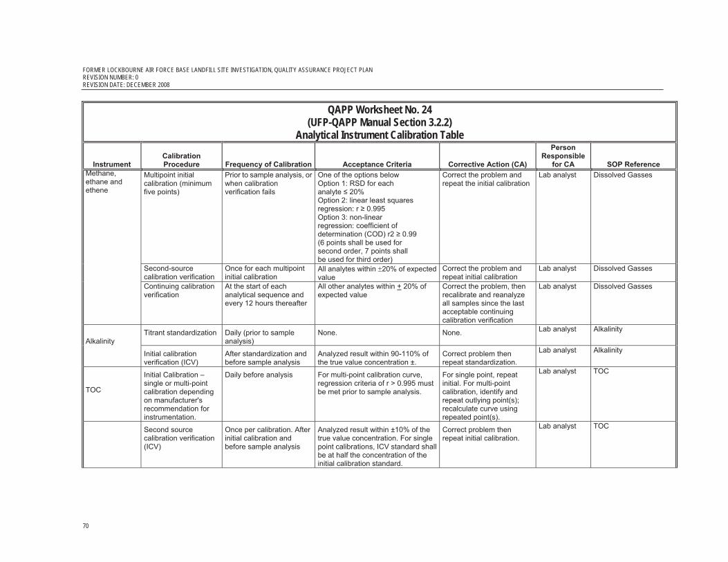
FORMER LOCKBOURNE AIR FORCE BASE LANDFILL SITE INVESTIGATION, QUALITY ASSURANCE PROJECT PLAN REVISION NUMBER: 0 REVISION DATE: DECEMBER 2008
70
QAPP Worksheet No. 24 (UFP-QAPP Manual Section 3.2.2)
Analytical Instrument Calibration Table
Instrument Calibration Procedure Frequency of Calibration Acceptance Criteria Corrective Action (CA)
PersonResponsible
for CA SOP Reference Multipoint initial calibration (minimum five points)
Prior to sample analysis, or when calibration verification fails
One of the options below Option 1: RSD for each analyte � 20% Option 2: linear least squares regression: r � 0.995 Option 3: non-linear regression: coefficient of determination (COD) r2 � 0.99 (6 points shall be used for second order, 7 points shall be used for third order)
Correct the problem and repeat the initial calibration
Lab analyst Dissolved Gasses
Second-source calibration verification
Once for each multipoint initial calibration
All analytes within �20% of expected value
Correct the problem and repeat initial calibration
Lab analyst Dissolved Gasses
Methane, ethane and ethene
Continuing calibration verification
At the start of each analytical sequence and every 12 hours thereafter
All other analytes within + 20% of expected value
Correct the problem, then recalibrate and reanalyze all samples since the last acceptable continuing calibration verification
Lab analyst Dissolved Gasses
Titrant standardization Daily (prior to sample analysis)
None. None. Lab analyst Alkalinity Alkalinity Initial calibration
verification (ICV) After standardization and before sample analysis
Analyzed result within 90-110% of the true value concentration ±.
Correct problem then repeat standardization.
Lab analyst Alkalinity
TOC
Initial Calibration – single or multi-point calibration depending on manufacturer's recommendation for instrumentation.
Daily before analysis For multi-point calibration curve, regression criteria of r > 0.995 must be met prior to sample analysis.
For single point, repeat initial. For multi-point calibration, identify and repeat outlying point(s); recalculate curve using repeated point(s).
Lab analyst TOC
Second source calibration verification (ICV)
Once per calibration. After initial calibration and before sample analysis
Analyzed result within ±10% of the true value concentration. For single point calibrations, ICV standard shall be at half the concentration of the initial calibration standard.
Correct problem then repeat initial calibration.
Lab analyst TOC

FORMER LOCKBOURNE AIR FORCE BASE LANDFILL SITE INVESTIGATION, QUALITY ASSURANCE PROJECT PLAN REVISION NUMBER: 0
REVISION DATE: DECEMBER 2008
71
QAPP Worksheet No. 24 (UFP-QAPP Manual Section 3.2.2)
Analytical Instrument Calibration Table
Instrument Calibration Procedure Frequency of Calibration Acceptance Criteria Corrective Action (CA)
PersonResponsible
for CA SOP Reference
Sulfate and Chloride, nitrate/nitrite as nitrogen
Initial multipoint calibration for all analytes (minimum three standards and one calibration blank) (ICAL)
Initial calibration before sample analysis
Linear—RSD for each analyte � 10% or: linear—least squares regression r > 0.995 for each analyte.
Correct problem then repeat initial calibration.
Lab analyst Anions
Calibration verification: ICV and CCV
ICV: Daily, before sample analysis, unless ICAL performed on same day when effluent is changed CCV: After every 10 samples At the end of the analysis sequence
All analytes within � 10% of expected value (%D)
ICV: Correct problem, rerun ICV. If that fails, repeat initial calibration. CCV: Correct problem then repeat CCV. Reanalyze all samples since last successful calibration verification.
Lab analyst Anions
Field Analysis of Methane
Reference SOP 6 and Worksheet 22
Reference SOP 6 and Worksheet 22
Reference SOP 6 and Worksheet 22 Reference SOP 6 and Worksheet 22
Field Team Leader
SOP 6
1Specify the appropriate reference letter or number from the Analytical SOP References table (Worksheet No. 23). DFTPP = Decafluorotriphenylphosphine; %D = Percent Drift; %RSD = Percent Relative Standard Deviation; CC = Continuing Calibration; RRF = Relative Response Factor; IC = Initial Calibration; SPCC = System Performance Check Compound; RF = Response Factor; CCC = Calibration Check Compound, NA – Not applicable.

FORMER LOCKBOURNE AIR FORCE BASE LANDFILL SITE INVESTIGATION, QUALITY ASSURANCE PROJECT PLAN REVISION NUMBER: 0 REVISION DATE: DECEMBER 2008
72
QAPP Worksheet No. 25(UFP-QAPP Manual Section 3.2.3)
Analytical Instrument and Equipment Maintenance, Testing, and Inspection Table
Identify all analytical instruments that require maintenance, testing, or inspection and provide the SOP reference number for each. In addition, document the frequency, acceptance criteria, and corrective action requirements on the worksheet.
Worksheet Not Applicable (State Reason)
Note: All laboratory analytical equipment will undergo maintenance and testing procedures in accordance with the laboratory SOPs. Laboratory SOPs must be compliant with minimum method requirements. All applicable SOPs are provided for review in Attachment 1
Analytical Instrument and Equipment Maintenance, Testing, and Inspection TableInstrument/ Equipment
Maintenance Activity Testing Activity Inspection Activity Frequency
Acceptance Criteria
Corrective Action
Responsible Person SOP Reference1
GEM 2000 (field methane analysis)
Daily Calibration verification
Methane Analysis Check the calibration of the methane gas meter with standard calibration gas
Daily Per SOP Per SOP CH2M HILL Field Team Lead
SOP 6
Flame Ionization Detector (FID)
Daily Calibration verification
VOC Analysis Check the calibration of the methane gas meter with standard calibration gas
Daily Per SOP Per SOP CH2M HILL Field Team Lead
SOP 2
1Specify the appropriate reference letter or number from the Analytical SOP References table (Worksheet No. 23).

FORMER LOCKBOURNE AIR FORCE BASE LANDFILL SITE INVESTIGATION, QUALITY ASSURANCE PROJECT PLAN REVISION NUMBER: 0
REVISION DATE: DECEMBER 2008
73
QAPP Worksheet No. 26(UFP-QAPP Manual Appendix A)
Sampling Handling System
Use this worksheet to identify components of the project-specific sample handling system. Record personnel, and their organizational affiliations, who are primarily responsible for proper handling, custody, and storage of field samples from the time of collection, to laboratory delivery, to final sample disposal. Indicate the number of days field samples and their extracts and digestates will be archived prior to disposal.
Worksheet Not Applicable (State Reason)
Sample Handling SystemSAMPLE COLLECTION, PACKAGING, AND SHIPMENT
Sample Collection (Personnel/Organization): Field Team Leader or designee, CH2M HILL
Sample Packaging (Personnel/Organization): Field Team Leader or designee, CH2M HILL
Coordination of Shipment (Personnel/Organization): Field Team Leader or designee, CH2M HILL
Type of Shipment/Carrier: Overnight shipping via Federal Express
SAMPLE RECEIPT AND ANALYSIS
Sample Receipt (Personnel/Organization): CT Laboratories and Empirical Laboratories sample custodians
Sample Custody and Storage (Personnel/Organization): CT Laboratories and Empirical Laboratories sample custodians
Sample Preparation (Personnel/Organization): CT Laboratories and Empirical Laboratories specific analytical technicians
Sample Determinative Analysis (Personnel/Organization): CT Laboratories and Empirical Laboratories specific analytical technicians
SAMPLE ARCHIVING
Field Sample Storage (no. of days from sample collection): CT Laboratories and Empirical Laboratories sample custodian will store samples at the laboratory for 30 days after final report has been submitted to CH2M HILL
Sample Extract/Digestate Storage (no. of days from extraction/digestion): CT Laboratories and Empirical Laboratories specific analytical technicians will store all extracts/digestates for 30 days after final report has been submitted to CH2M HILL
Biological Sample Storage (no. of days from sample collection): NA
SAMPLE DISPOSAL
Personnel/Organization: CT Laboratories and Empirical Laboratories hazardous waste manager
Number of Days from Analysis: Samples may not be disposed of prior to 30 days after final report has been submitted to CH2M HILL.

FORMER LOCKBOURNE AIR FORCE BASE LANDFILL SITE INVESTIGATION, QUALITY ASSURANCE PROJECT PLAN REVISION NUMBER: 0 REVISION DATE: DECEMBER 2008
74
QAPP Worksheet No. 27 (UFP-QAPP Manual Section 3.3.3)
Sample Custody Requirements Describe the procedures that will be used to maintain sample custody and integrity. Include examples of chain-of-custody forms, traffic reports, sample identification, custody seals, laboratory sample receipt forms, and laboratory sample transfer forms. Attach or reference applicable SOPs.
Worksheet Not Applicable (State Reason)
QAPP Worksheet No. 27 (UFP-QAPP Manual Section 3.3.3)
Sample Custody Requirements Proper sample handling, shipment, and maintenance of a chain-of-custody (COC) are key components of building the documentation and support for data that can be used to make project decisions. It is important that sample handling and sample COC requirements are performed completely, accurately, and consistently.
Field Sample Custody Procedures:
Reference CH2M HILL's SOPs 11 and 12
Field sampling activities require several forms of documentation to maintain sample ID and COC and to record significant events or observations. Required documentation will include log-books and other field forms, including sample registers, field sampling forms, field change request documentation, and daily field progress reports as appropriate.
Sample Labeling Self-adhesive sample labels will be provided by the project laboratory and affixed to each sample container. The sample label will be completed in indelible ink and will include the following information:
� Project name � Sample ID number � Date and time of sample collection � Sampler’s initials � Sample type (water) � Preservative used (N/A if not required) � Analyses requested
Sample labels will be affixed to the sample containers and covered with clear packaging tape.
Packaging and Shipping Procedures
Samples will immediately be placed in a cooler filled with ice for temporary storage prior to shipment to the laboratory and during final shipment to the laboratory. All samples will be packaged and labeled for shipment in compliance with current regulations. Only metal or plastic ice chests will be used for shipping samples. For shipment to the laboratory, samples

FORMER LOCKBOURNE AIR FORCE BASE LANDFILL SITE INVESTIGATION, QUALITY ASSURANCE PROJECT PLAN REVISION NUMBER: 0
REVISION DATE: DECEMBER 2008
75
QAPP Worksheet No. 27 (UFP-QAPP Manual Section 3.3.3)
Sample Custody Requirements will be properly padded to prevent breakage. Ice used in the coolers for shipping to the laboratories will be placed in double, 1-gallon, zip-lock bags with a minimum amount of air. The COC record will be placed inside a zip-lock plastic bag and taped to the inside of the cooler top. The cooler will be closed and taped shut with packing tape or duct tape, and a custody seal will be properly placed across two sides of the cooler lid. The shipping air bill, if needed, will be securely attached to the exterior of the cooler. Commercial carriers or sample pickup couriers are not required to sign the COC record if it is sealed inside the shipping cooler and the custody seals remain intact. The laboratory is responsible for storing the samples in a secure location and following all COC procedures. Samples will be collected in certified clean containers provided by the project laboratory. All samples will be shipped to the laboratory by Federal Express overnight.
COC Procedures:
A COC record establishes the documentation necessary to trace sample possession from time of collection through sample analysis and disposition. An example of the laboratory COC as well as a sample custody seal is provided as Attachment 3 to this QAPP. A sample is in the custody of a person if any of the following criteria are met:
� The sample is in a person's physical possession. � The sample is in a person's view after being in his or her physical possession. � The sample was in a person's physical possession and was then locked up or sealed to
prevent tampering. � The sample is kept in a secured area.
The sample collector will complete a COC record to accompany each delivery container (cooler) and will be responsible for shipping samples to the laboratory. The sample collector will provide the project number and their signature in the designated fields at the top of the COC record. For each sample submitted to the project laboratory, the sample collector will indicate the date, time, number of containers, analytical parameters, and designated sample ID numbers. When shipping the samples, the sample collector will sign the bottom of the form and enter the date and time (24-hour) at which samples were relinquished. Lines not used on the COC record will be crossed out. The sample collector will enter the carrier name on the form. Any required special handling of analyzed samples, such as hold or return, must be written on the COC record. A second member of the field crew will review the completed COC record to assure that required information is not omitted and that unused lines are crossed out. The original signature copy of the COC record will be enclosed in a plastic bag and secured to the inside of the cooler lid. A copy of the COC record will be retained for project files.
Laboratory Sample Custody Procedures (receipt of samples, archiving, and disposal):
A designated sample custodian accepts the shipped samples, and verifies that the packing list sample numbers match those on the COC records. Pertinent information regarding

FORMER LOCKBOURNE AIR FORCE BASE LANDFILL SITE INVESTIGATION, QUALITY ASSURANCE PROJECT PLAN REVISION NUMBER: 0 REVISION DATE: DECEMBER 2008
76
QAPP Worksheet No. 27 (UFP-QAPP Manual Section 3.3.3)
Sample Custody Requirements shipment, pickup, and courier is entered in the section for remarks.
The laboratory sample custodian will reconcile the information on the COC records with the sample bottles received. The sample custodian will document any anomalies and report these to the laboratory project manager. Anomalies will be resolved with the project chemist.
Photographs are recommended to document the condition of samples if significant out-of-control conditions are noted at the time the samples are received. The sample custodian must fax a copy of the cooler receipt form, the associated COC records, and the sample delivery group (SDG) assignment form to the project chemist within 24 hours of sample receipt. The information on the forms will then be entered into the laboratory information management system (LIMS) along with the analyses being requested.
The sample laboratory custodian is responsible for seeing that all samples are transferred to the proper analyst or stored in the appropriate secure area. Laboratory personnel are responsible for the care and custody of samples from the time they are received, until the sample is exhausted or returned to the custodian using an internal COC record to track sample movement within the laboratory. When sample analyses and necessary QA checks have been completed in the laboratory, the unused portion of the sample will be disposed of properly. All identifying stickers, data sheets, and laboratory records are retained as part of the documentation. Sample containers and remaining samples are disposed of in compliance with all federal, state, and local regulatory requirements.

FORMER LOCKBOURNE AIR FORCE BASE LANDFILL SITE INVESTIGATION, QUALITY ASSURANCE PROJECT PLAN REVISION NUMBER: 0
REVISION DATE: DECEMBER 2008
77
QAPP Worksheet No. 28-1 (UFP-QAPP Manual Section 3.4)
QC Samples Table
Complete a separate worksheet for each sampling technique, analytical method and SOP, matrix, analytical group, and concentration level. If method and SOP QC acceptance limits exceed the measurement performance criteria, the data obtained may be unusable for making project decisions.
Worksheet Not Applicable (State Reason)
Matrix Seep Water Analytical Group Volatiles
Concentration Level NA Sampling SOP1 SOP-8
Analytical Method/ SOP Reference SW8260B / VOCs
Field Team Leader Matt Gale Field Sampling Organization CH2M HILL
Analytical Organization CT Laboratories and Empirical Laboratories
No. of Sample Locations 6
QC Sample Frequency/ Number
Method/SOP QC Acceptance
Limits Corrective Action
Person(s) Responsible for
Corrective Action2
Data Quality Indicator (DQI)
Measurement Performance Criteria
Trip Blank Not applicable to
soil sample collection
NA NA Data Validation Lead accuracy NA
Field Duplicate One per 10 field samples
Should meet RPD criteria of 30% for treatment water/
surface water
Qualify data as necessary Data Validation Lead
Precision and/ accuracy
Should meet RPD criteria of 30% for treatment water/
surface water
Method Blank
1 per 12-hour period in which
samples are analyzed
All target compounds < 1/2RL except
common contaminants < RL
If contaminated, find and eliminate source of contamination. Reanalyze along with any
associated samples
Lab Analyst Representativeness and accuracy
All target compounds < 1/2RL except common contaminants
< RL
Surrogate Spikes
Added to all samples and QC
samples per the lab SOP
Reference worksheet 15 Reanalyze samples as necessary Lab Analyst Accuracy Reference Worksheet 15
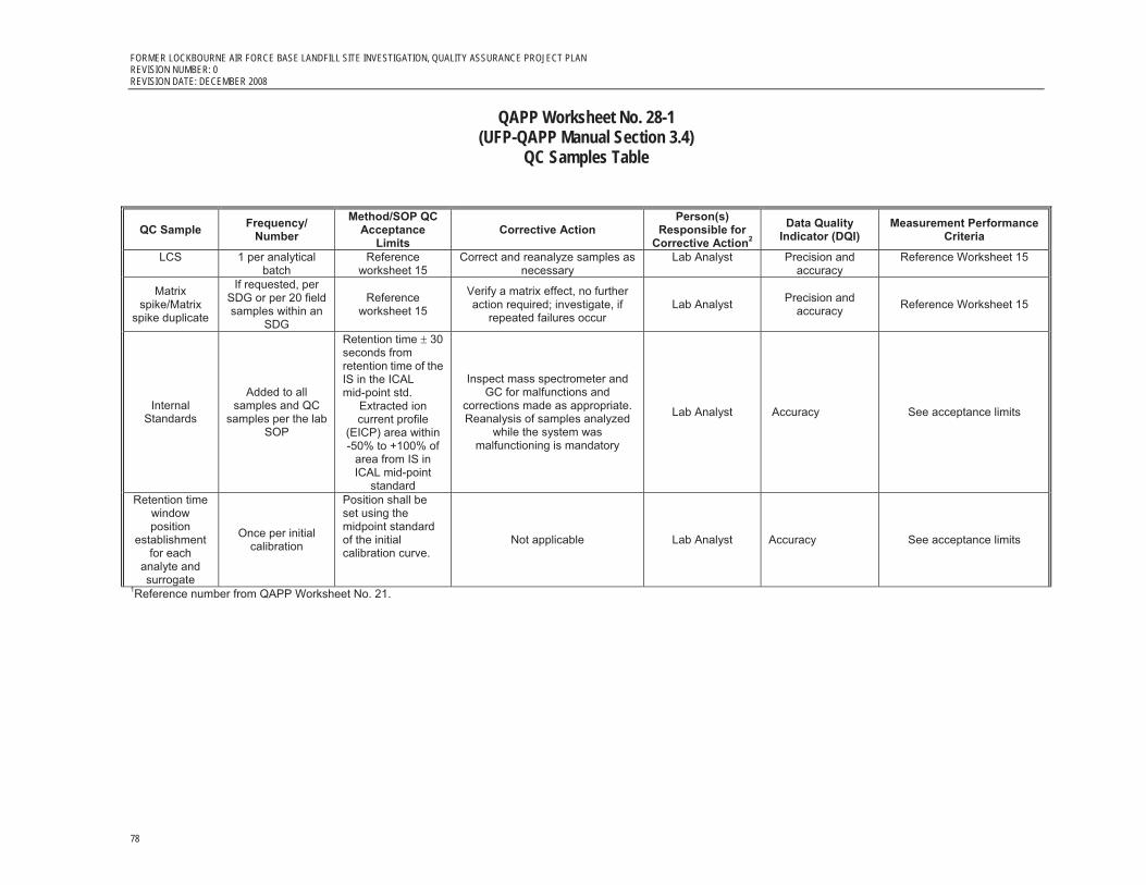
FORMER LOCKBOURNE AIR FORCE BASE LANDFILL SITE INVESTIGATION, QUALITY ASSURANCE PROJECT PLAN REVISION NUMBER: 0 REVISION DATE: DECEMBER 2008
78
QAPP Worksheet No. 28-1 (UFP-QAPP Manual Section 3.4)
QC Samples Table
QC Sample Frequency/ Number
Method/SOP QC Acceptance
Limits Corrective Action
Person(s) Responsible for
Corrective Action2
Data Quality Indicator (DQI)
Measurement Performance Criteria
LCS 1 per analytical batch
Reference worksheet 15
Correct and reanalyze samples as necessary
Lab Analyst Precision and accuracy
Reference Worksheet 15
Matrix spike/Matrix
spike duplicate
If requested, per SDG or per 20 field samples within an
SDG
Reference worksheet 15
Verify a matrix effect, no further action required; investigate, if
repeated failures occur Lab Analyst Precision and
accuracy Reference Worksheet 15
Internal Standards
Added to all samples and QC
samples per the lab SOP
Retention time � 30 seconds from retention time of the IS in the ICAL mid-point std.
Extracted ion current profile
(EICP) area within -50% to +100% of
area from IS in ICAL mid-point
standard
Inspect mass spectrometer and GC for malfunctions and
corrections made as appropriate. Reanalysis of samples analyzed
while the system was malfunctioning is mandatory
Lab Analyst Accuracy See acceptance limits
Retention time window position
establishment for each
analyte and surrogate
Once per initial calibration
Position shall be set using the midpoint standard of the initial calibration curve.
Not applicable Lab Analyst Accuracy See acceptance limits
1Reference number from QAPP Worksheet No. 21.

FORMER LOCKBOURNE AIR FORCE BASE LANDFILL SITE INVESTIGATION, QUALITY ASSURANCE PROJECT PLAN REVISION NUMBER: 0
REVISION DATE: DECEMBER 2008
79
QAPP Worksheet No. 28-2 (UFP-QAPP Manual Section 3.4)
QC Samples Table
Matrix Seep Water Analytical Group SVOC PAHs and Dioxins/furans
Concentration Level NA Sampling SOP1 SOP-8
Analytical Method/ SOP Reference
SW8270CSIM / Semivolatiles and SW8290 / Dioxins/Furans
Field Team Leader Matt Gale Field Sampling Organization CH2M HILL
Analytical Organization CT Laboratories and Empirical
Laboratories; dioxins/furans will be subcontracted to TA Sacramento California
and SGS Lab in North Carolina No. of Sample Locations 6
QC Sample Frequency/ Number
Method/SOP QC Acceptance Limits Corrective Action
Person(s) Responsible for
Corrective Action2
Data Quality Indicator (DQI)
Measurement Performance Criteria
Field Duplicate One per 10 field samples
Should meet RPD criteria of 30% for
treatment water/surface water
Qualify data as necessary Data Validation Lead
Precision and accuracy
Should meet RPD criteria of 30% for treatment
water/surface water
Method Blank 1 per extraction
batch not to exceed 20 field samples
All target compounds < 1/2RL except
common contaminants < RL
If contaminated, find and eliminate the source. If internal or surrogate standard fail acceptance criteria; reanalyze. If surrogates continue to fail, re-extract and reanalyze
along with all associated samples
Lab Analyst Representativeness and accuracy
All target compounds < 1/2RL except common
contaminants < RL
Surrogate Spikes
Added to all samples and QC
samples per the lab SOP
Reference Worksheet 15 Reanalyze samples as necessary Lab Analyst Accuracy Reference Worksheet 15
LCS 1 per analytical batch
Reference Worksheet 15
Correct and reanalyze samples as necessary Lab Analyst Precision and
accuracy Reference Worksheet 15
Matrix spike/Matrix
spike duplicate
if requested, per 20 field samples; per concentration level
Reference Worksheet 15
No further action required; investigate if repeated failures
occur Lab Analyst Precision and
accuracy Reference Worksheet 15

FORMER LOCKBOURNE AIR FORCE BASE LANDFILL SITE INVESTIGATION, QUALITY ASSURANCE PROJECT PLAN REVISION NUMBER: 0 REVISION DATE: DECEMBER 2008
80
QAPP Worksheet No. 28-2 (UFP-QAPP Manual Section 3.4)
QC Samples Table
QC Sample Frequency/ Number
Method/SOP QC Acceptance Limits
Corrective Action Person(s)
Responsible for Corrective Action2
Data Quality Indicator (DQI)
Measurement Performance Criteria
Internal Standards
Added to all samples and QC
samples per the lab SOP
Retention time � 30 seconds from retention time of the IS in the ICAL mid-point std.
Extracted ion current profile
(EICP) area within -50% to +100% of
area from IS in ICAL mid-point
standard
Inspect mass spectrometer and GC for malfunctions and
corrections made as appropriate. Reanalysis of samples analyzed
while the system was malfunctioning is mandatory
Lab Analyst accuracy See acceptance limits
Retention time window position
establishment for each
analyte and surrogate
Once per initial calibration
Position shall be set using the midpoint standard of the initial calibration curve.
Not applicable Lab Analyst accuracy See acceptance limits
GC Performance
Check
Daily before analysis of sample
or calibration standards
Degradation � 20% for DDT. No visible peak tailing for benzidine or pentachlorophenol (As a default, tailing factors should be less than 3.0 and 5.0, respectively.)
Correct problem, then repeat performance check
Lab Analyst accuracy See acceptance limits
1Reference number from QAPP Worksheet No. 21.

FORMER LOCKBOURNE AIR FORCE BASE LANDFILL SITE INVESTIGATION, QUALITY ASSURANCE PROJECT PLAN REVISION NUMBER: 0
REVISION DATE: DECEMBER 2008
81
QAPP Worksheet No. 28-3 (UFP-QAPP Manual Section 3.4)
QC Samples Table
Matrix Seep Water Analytical Group Total or dissolved Metals
Concentration Level NA Sampling SOP1 SOP-8
Analytical Method/ SOP Reference SW6010B / Metals by ICP or SW7060A / Metals by GFAA
Field Team Leader Matt Gale Field Sampling Organization CH2M HILL
Analytical Organization CT Laboratories and Empirical Laboratories No. of Sample Locations 6
QC Sample Frequency/ Number Method/SOP QC Acceptance Limits Corrective Action
Person(s) Responsible for
Corrective Action2
Data Quality Indicator (DQI)
Measurement Performance
Criteria
Field Duplicate One per 10 field samples
should meet RPD criteria of 30% for
treatment water/surface water
Qualify data as necessary Data Validation Lead
Precision and accuracy
Should meet RPD criteria of 30% for
treatment water/surface
water
Calibration Blank
Following each initial and continuing calibration; every 2 hours or every 10 analytical samples, whichever is more
frequent
absolute values of all analyte concentrations
must be < ½ RL
Stop analysis; correct problem; recalibrate Lab Analyst Representativeness
and accuracy
Absolute values of all analyte
concentrations must be < ½ RL
Preparation blank (PB) 1 per digestion batch
absolute values of all analyte concentrations
must be � ½ RL
Re-prepare and reanalyze; except if concentration of
analyte(s) in all associated samples is > 10x the
concentration in the blank
Lab Analyst Representativeness and accuracy
Absolute values of all analyte
concentrations must be � ½ RL
Interference Check Sample (ICS)
The beginning of the analytical sequence not required for
mercury or Cyanide analyses
20% of the analytes true value in the ICSAB
solution
Check system. Correct problem. Recalibrate Lab Analyst Accuracy and bias
20% of the analytes true value
in the ICSAB solution
Matrix Spike 1 per SDG Reference Worksheet
15
Analyze a post-digestion spike (POS), if recoveries fail and analyte concentration is < 4x
the spike added (POS not required for Hg)
Lab Analyst Accuracy and bias Reference worksheet 15

FORMER LOCKBOURNE AIR FORCE BASE LANDFILL SITE INVESTIGATION, QUALITY ASSURANCE PROJECT PLAN REVISION NUMBER: 0 REVISION DATE: DECEMBER 2008
82
QAPP Worksheet No. 28-3 (UFP-QAPP Manual Section 3.4)
QC Samples Table
QC Sample Frequency/ Number Method/SOP QC Acceptance Limits Corrective Action
Person(s) Responsible for
Corrective Action2
Data Quality Indicator (DQI)
Measurement Performance
Criteria
LCS 1 per SDG or per preparation
batch, whichever is more frequent
Reference Worksheet 15
Re-prepare and reanalyze digestion batch Lab Analyst Accuracy and bias Reference
worksheet 15
Laboratory Duplicate 1 per SDG
RPD of 20%, if concentration is > 5x RL; or ± the RL if the concentration is < 5x
RL
Reanalyze once to verify results Lab Analyst Precision and accuracy
RPD of 20%, if concentration is > 5x RL; or ± the RL if the concentration
is < 5x RL
Serial Dilution
1 per SDG; not required for Mercury and Cyanide analysis
Should agree within 10% of the original
sample Reanalyze once to verify results Lab Analyst Precision and
accuracy
Should agree within 10% of the original sample
Post digestion
spike addition
When dilution test fails or if an analyte’s concentration for all
samples in a batch is less than 50X MDL
Recovery within 75-–125% of expected
results
Check for instrumental problem then reanalyze post digestion spike addition if appropriate. Lab Analyst Precision and
accuracy See acceptance
criteria
1Reference number from QAPP Worksheet No. 21.
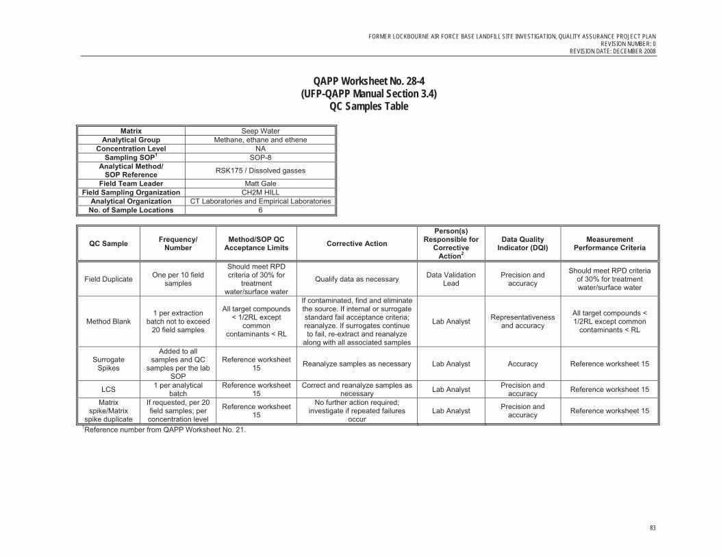
FORMER LOCKBOURNE AIR FORCE BASE LANDFILL SITE INVESTIGATION, QUALITY ASSURANCE PROJECT PLAN REVISION NUMBER: 0
REVISION DATE: DECEMBER 2008
83
QAPP Worksheet No. 28-4 (UFP-QAPP Manual Section 3.4)
QC Samples Table
Matrix Seep Water Analytical Group Methane, ethane and ethene
Concentration Level NA Sampling SOP1 SOP-8
Analytical Method/ SOP Reference RSK175 / Dissolved gasses
Field Team Leader Matt Gale Field Sampling Organization CH2M HILL
Analytical Organization CT Laboratories and Empirical LaboratoriesNo. of Sample Locations 6
QC Sample Frequency/ Number
Method/SOP QC Acceptance Limits Corrective Action
Person(s) Responsible for
Corrective Action2
Data Quality Indicator (DQI)
Measurement Performance Criteria
Field Duplicate One per 10 field samples
Should meet RPD criteria of 30% for
treatment water/surface water
Qualify data as necessary Data Validation Lead
Precision and accuracy
Should meet RPD criteria of 30% for treatment water/surface water
Method Blank 1 per extraction
batch not to exceed 20 field samples
All target compounds < 1/2RL except
common contaminants < RL
If contaminated, find and eliminate the source. If internal or surrogate standard fail acceptance criteria; reanalyze. If surrogates continue to fail, re-extract and reanalyze
along with all associated samples
Lab Analyst Representativeness and accuracy
All target compounds < 1/2RL except common
contaminants < RL
Surrogate Spikes
Added to all samples and QC
samples per the lab SOP
Reference worksheet 15 Reanalyze samples as necessary Lab Analyst Accuracy Reference worksheet 15
LCS 1 per analytical batch
Reference worksheet 15
Correct and reanalyze samples as necessary Lab Analyst Precision and
accuracy Reference worksheet 15
Matrix spike/Matrix
spike duplicate
If requested, per 20 field samples; per concentration level
Reference worksheet 15
No further action required; investigate if repeated failures
occur Lab Analyst Precision and
accuracy Reference worksheet 15
1Reference number from QAPP Worksheet No. 21.
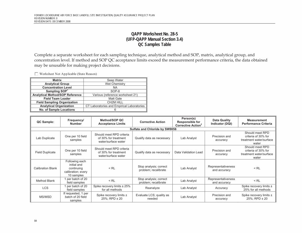
FORMER LOCKBOURNE AIR FORCE BASE LANDFILL SITE INVESTIGATION, QUALITY ASSURANCE PROJECT PLAN REVISION NUMBER: 0 REVISION DATE: DECEMBER 2008
84
QAPP Worksheet No. 28-5 (UFP-QAPP Manual Section 3.4)
QC Samples Table
Complete a separate worksheet for each sampling technique, analytical method and SOP, matrix, analytical group, and concentration level. If method and SOP QC acceptance limits exceed the measurement performance criteria, the data obtained may be unusable for making project decisions.
Worksheet Not Applicable (State Reason) Matrix Seep Water
Analytical Group Wet Chemistry Concentration Level NA
Sampling SOP1 SOP-8 Analytical Method/SOP Reference Various (reference worksheet 21)
Field Team Leader Matt Gale Field Sampling Organization CH2M HILL
Analytical Organization CT Laboratories and Empirical LaboratoriesNo. of Sample Locations 6
QC Sample: Frequency/ Number
Method/SOP QC Acceptance Limits Corrective Action
Person(s) Responsible for
Corrective Action2
Data Quality Indicator (DQI)
Measurement Performance Criteria
Sulfate and Chloride by SW9056
Lab Duplicate One per 10 field samples
Should meet RPD criteria of 30% for treatment water/surface water
Qualify data as necessary Lab Analyst Precision and accuracy
Should meet RPD criteria of 30% for
treatment water/surface water
Field Duplicate One per 10 field samples
Should meet RPD criteria of 30% for treatment water/surface water
Qualify data as necessary Data Validation Lead Precision and accuracy
Should meet RPD criteria of 30% for
treatment water/surface water
Calibration Blank
Following each initial and continuing
calibration; every 10 samples
< RL Stop analysis; correct problem; recalibrate Lab Analyst Representativeness
and accuracy < RL
Method Blank 1 per batch of 20 field samples < RL Stop analysis; correct
problem; recalibrate Lab Analyst Representativeness and accuracy < RL
LCS 1 per batch of 20 field samples
Spike recovery limits ± 25% for all methods Reanalyze Lab Analyst Accuracy Spike recovery limits ±
25% for all methods
MS/MSD If requested, 1 per batch of 20 field
samples
Spike recovery limits ± 25%; RPD ± 20
Evaluate LCS; quality as needed Lab Analyst Precision and
accuracy Spike recovery limits ±
25%; RPD ± 20

FORMER LOCKBOURNE AIR FORCE BASE LANDFILL SITE INVESTIGATION, QUALITY ASSURANCE PROJECT PLAN REVISION NUMBER: 0
REVISION DATE: DECEMBER 2008
85
QAPP Worksheet No. 28-5 (UFP-QAPP Manual Section 3.4)
QC Samples Table Retention time window width established for each analyte
At method set-up and after major
maintenance (for example, column
change
Width is ± 3 times standard deviation for each analyte
retention time over 24-hour period.
N/A
Lab Analyst Accuracy See acceptance criteria
Retention time window verified for
each analyte
Each calibration verification
Analyte within established window
Correct problem then reanalyze all samples analyzed since the last
acceptable retention time check.
Lab Analyst Accuracy See acceptance criteria
Nitrate/nitrite as nitrogen by SW9056 by a preserved sample
Lab Duplicate One per 10 field samples
Should meet RPD criteria of 30% for treatment water/surface water
Qualify data as necessary Lab Analyst Precision and accuracy
Should meet RPD criteria of 30% for
treatment water/surface water
Field Duplicate One per 10 field samples
Should meet RPD criteria of 30% for treatment water/surface water
Qualify data as necessary Data Validation Lead Precision and accuracy
Should meet RPD criteria of 30% for
treatment water/surface water
Calibration Blank
Following each initial and continuing
calibration; every 10 samples
< RL Stop analysis; correct problem; recalibrate Lab Analyst Representativeness
and accuracy < RL
Method Blank 1 per batch of 20 field samples < RL Stop analysis; correct
problem; recalibrate Lab Analyst Representativeness and accuracy < RL
LCS 1 per batch of 20 field samples
Spike recovery limits ± 25% for all methods reanalyze Lab Analyst Accuracy Spike recovery limits ±
25% for all methods
MS/MSD If requested, 1 per batch of 20 field
samples
Spike recovery limits ± 25%; RPD ± 20
Evaluate LCS; quality as needed Lab Analyst Precision and
accuracy Spike recovery limits ±
25%; RPD ± 20
Retention time window width established for each analyte
At method set-up and after major
maintenance (for example, column
change
Width is ± 3 times standard deviation for each analyte
retention time over 24-hour period.
N/A
Lab Analyst Accuracy See acceptance criteria
Retention time window verified for
each analyte
Each calibration verification
Analyte within established window
Correct problem then reanalyze all samples analyzed since the last
acceptable retention time check.
Lab Analyst Accuracy See acceptance criteria
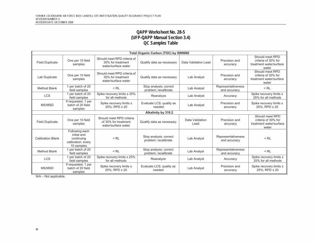
FORMER LOCKBOURNE AIR FORCE BASE LANDFILL SITE INVESTIGATION, QUALITY ASSURANCE PROJECT PLAN REVISION NUMBER: 0 REVISION DATE: DECEMBER 2008
86
QAPP Worksheet No. 28-5 (UFP-QAPP Manual Section 3.4)
QC Samples Table
Total Organic Carbon (TOC) by SW9060
Field Duplicate One per 10 field samples
Should meet RPD criteria of 30% for treatment
water/surface water Qualify data as necessary Data Validation Lead Precision and
accuracy
Should meet RPD criteria of 30% for
treatment water/surface water
Lab Duplicate One per 10 field samples
Should meet RPD criteria of 30% for treatment
water/surface water Qualify data as necessary Lab Analyst Precision and
accuracy
Should meet RPD criteria of 30% for
treatment water/surface water
Method Blank 1 per batch of 20 field samples < RL Stop analysis; correct
problem; recalibrate Lab Analyst Representativeness and accuracy < RL
LCS 1 per batch of 20 field samples
Spike recovery limits ± 25% for all methods Reanalyze Lab Analyst Accuracy Spike recovery limits ±
25% for all methods
MS/MSD If requested, 1 per batch of 20 field
samples
Spike recovery limits ± 25%; RPD ± 20
Evaluate LCS; quality as needed Lab Analyst Precision and
accuracy Spike recovery limits ±
25%; RPD ± 20
Alkalinity by 310.2
Field Duplicate One per 10 field samples
Should meet RPD criteria of 30% for treatment water/surface water
Qualify data as necessary Data Validation Lead
Precision and accuracy
Should meet RPD criteria of 30% for
treatment water/surface water
Calibration Blank
Following each initial and continuing
calibration; every 10 samples
< RL Stop analysis; correct problem; recalibrate Lab Analyst Representativeness
and accuracy < RL
Method Blank 1 per batch of 20 field samples < RL Stop analysis; correct
problem; recalibrate Lab Analyst Representativeness and accuracy < RL
LCS 1 per batch of 20 field samples
Spike recovery limits ± 25% for all methods Reanalyze Lab Analyst Accuracy Spike recovery limits ±
25% for all methods
MS/MSD If requested, 1 per batch of 20 field
samples
Spike recovery limits ± 25%; RPD ± 20
Evaluate LCS; quality as needed Lab Analyst Precision and
accuracy Spike recovery limits ±
25%; RPD ± 20
N/A – Not applicable.

FORMER LOCKBOURNE AIR FORCE BASE LANDFILL SITE INVESTIGATION, QUALITY ASSURANCE PROJECT PLAN REVISION NUMBER: 0
REVISION DATE: DECEMBER 2008
87
QAPP Worksheet No. 29 (UFP-QAPP Manual Section 3.5.1)
Project Documents and Records Table
Identify the documents and records that will be generated for all aspects of the project including, but not limited to, sample collection and field measurement, onsite and offsite analysis, and data assessment.
Worksheet Not Applicable (State Reason)
Project Documents and Records TableSample Collection Documents
and Records Onsite Analysis Documents
and Records Offsite Analysis Documents and Records Data Assessment
Documents and Records Other
Daily Field Notes/observations COC and shipping Records Telephone Logs Corrective Action Forms GIS information Waste profile information QA review records
Equipment Maintenance, Testing, and Inspection Logs Corrective Action Forms Checklists Telephone Logs QA Review Records
Hard copy analytical data will consist of a full summary data deliverable that utilizes summary forms such as those used in the CLP format. Forms may be CLP equivalnet deliverables. The summary forms will allow for data validation as defined in Worksheet 14 and include the the data deliverable details as defined in worksheet 11
Data validation reports ADR files Corrective action forms Telephone logs QA review records
Project database for analytical and field data Health and Safety Briefing information Staff health and safety records

FORMER LOCKBOURNE AIR FORCE BASE LANDFILL SITE INVESTIGATION, QUALITY ASSURANCE PROJECT PLAN REVISION NUMBER: 0 REVISION DATE: DECEMBER 2008
88
QAPP Worksheet No. 30(UFP-QAPP Manual Section 3.5.2.3)
Analytical Services Table
Complete this worksheet for each matrix, analytical group, and concentration level. Identify all laboratories or organizations that will provide analytical services for the project, including onsite screening, onsite definitive, and offsite laboratory analytical work. If applicable, identify the subcontractor laboratories and backup laboratory or organization that will be used if the primary laboratory or organizations cannot be used.
Worksheet Not Applicable (State Reason)
QAPP Worksheet No. 30
(UFP-QAPP Manual Section 3.5.2.3) Analytical Services Table
Matrix Analytical
Group Concentration
Level
SampleLocations/ID
Numbers Analytical
SOP Data Package
Turnaround Time
Laboratory/ Organization (Name and Address, Contact
Person and Telephone Number)
Backup Laboratory/Organization
(Name and Address, Contact Person and Telephone Number)
Seep Water All analyte groups
N/A All samples Reference SOPs defined in Worksheet 23
Standard turn around time will be 21 days from date of receipt at the laboratory for water samples.
Final follow-up data validation will be performed as soon as possible as final data packages arrive.
Primary Laboratory: CT Laboratories 1230 Lange Ct Baraboo, WI 53913 phone: 608-356-2760 fax: 608-356-2766 Eric Korthals [email protected]
QA Split Laboratory: Empirical Laboratories 277 French Landing Drive Suite 550 Nashville TN 37228 Marcia McGinnity 615-345-1115 [email protected]
There is no backup laboratory planned at this time due to the low numbers of samples planned for collection.

FORMER LOCKBOURNE AIR FORCE BASE LANDFILL SITE INVESTIGATION, QUALITY ASSURANCE PROJECT PLAN REVISION NUMBER: 0
REVISION DATE: DECEMBER 2008
89
QAPP Worksheet No. 30(UFP-QAPP Manual Section 3.5.2.3)
Analytical Services Table
Matrix Analytical
Group Concentration
Level
SampleLocations/ID
Numbers Analytical
SOP Data Package
Turnaround Time
Laboratory/ Organization (Name and Address, Contact
Person and Telephone Number)
Backup Laboratory/Organization
(Name and Address, Contact Person and Telephone Number)
Field methane analysis
methane NA Exact locations will be determined in the field based on conditions. Reference Figure 2-2 for general proposed locations of 20 samples
SOP 6 Documentation completed daily in the field
CH2M HILL field Team leader Matt Gale 937-220-2905 [email protected]
None needed
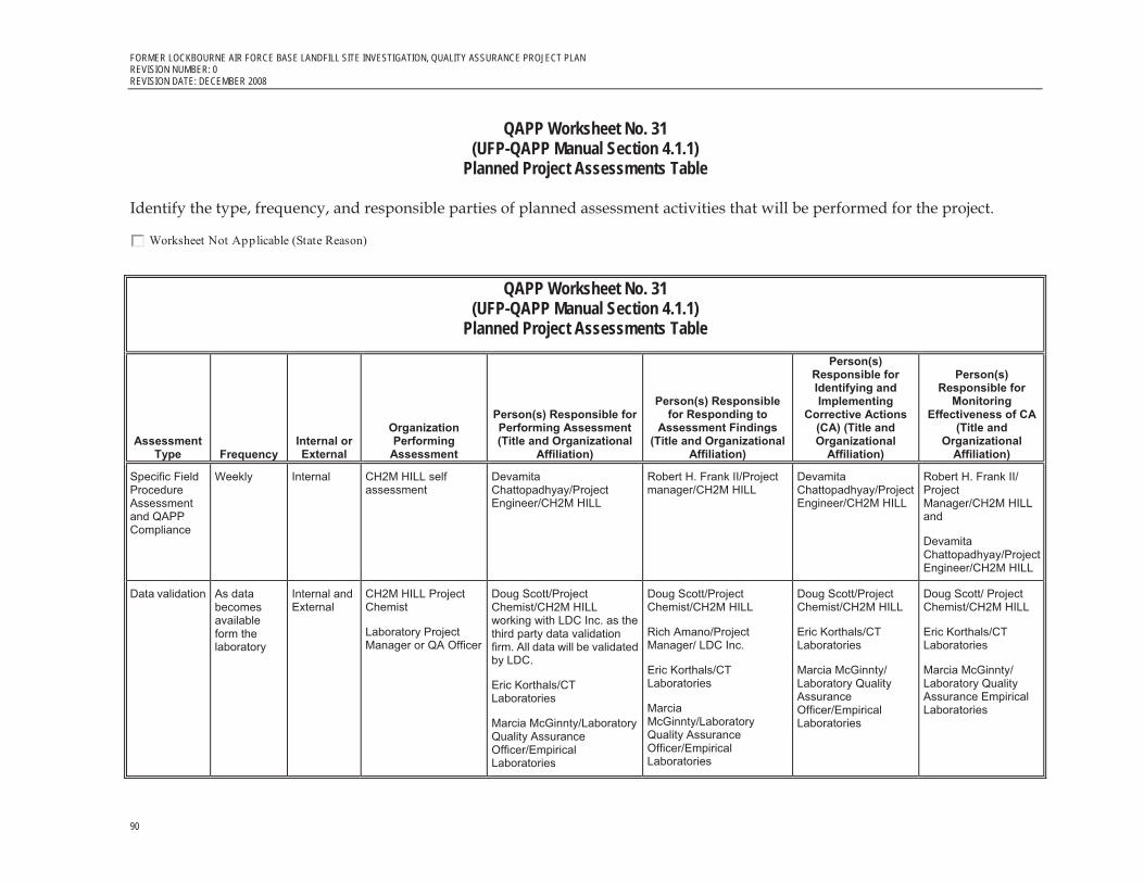
FORMER LOCKBOURNE AIR FORCE BASE LANDFILL SITE INVESTIGATION, QUALITY ASSURANCE PROJECT PLAN REVISION NUMBER: 0 REVISION DATE: DECEMBER 2008
90
QAPP Worksheet No. 31(UFP-QAPP Manual Section 4.1.1)
Planned Project Assessments Table
Identify the type, frequency, and responsible parties of planned assessment activities that will be performed for the project.
Worksheet Not Applicable (State Reason)
QAPP Worksheet No. 31
(UFP-QAPP Manual Section 4.1.1) Planned Project Assessments Table
Assessment Type Frequency
Internal or External
Organization Performing
Assessment
Person(s) Responsible for Performing Assessment (Title and Organizational
Affiliation)
Person(s) Responsible for Responding to
Assessment Findings (Title and Organizational
Affiliation)
Person(s) Responsible for Identifying and Implementing
Corrective Actions (CA) (Title and Organizational
Affiliation)
Person(s) Responsible for
Monitoring Effectiveness of CA
(Title and Organizational
Affiliation)
Specific Field Procedure Assessment and QAPP Compliance
Weekly Internal CH2M HILL self assessment
Devamita Chattopadhyay/Project Engineer/CH2M HILL
Robert H. Frank II/Project manager/CH2M HILL
Devamita Chattopadhyay/Project Engineer/CH2M HILL
Robert H. Frank II/ Project Manager/CH2M HILL and
Devamita Chattopadhyay/Project Engineer/CH2M HILL
Data validation As data becomes available form the laboratory
Internal and External
CH2M HILL Project Chemist
Laboratory Project Manager or QA Officer
Doug Scott/Project Chemist/CH2M HILL working with LDC Inc. as the third party data validation firm. All data will be validated by LDC.
Eric Korthals/CT Laboratories
Marcia McGinnty/Laboratory Quality Assurance Officer/Empirical Laboratories
Doug Scott/Project Chemist/CH2M HILL
Rich Amano/Project Manager/ LDC Inc.
Eric Korthals/CT Laboratories
Marcia McGinnty/Laboratory Quality Assurance Officer/Empirical Laboratories
Doug Scott/Project Chemist/CH2M HILL
Eric Korthals/CT Laboratories
Marcia McGinnty/ Laboratory Quality Assurance Officer/Empirical Laboratories
Doug Scott/ Project Chemist/CH2M HILL
Eric Korthals/CT Laboratories
Marcia McGinnty/ Laboratory Quality Assurance Empirical Laboratories

FORMER LOCKBOURNE AIR FORCE BASE LANDFILL SITE INVESTIGATION, QUALITY ASSURANCE PROJECT PLAN REVISION NUMBER: 0
REVISION DATE: DECEMBER 2008
91
QAPP Worksheet No. 31(UFP-QAPP Manual Section 4.1.1)
Planned Project Assessments Table
Assessment Type Frequency
Internal or External
Organization Performing
Assessment
Person(s) Responsible for Performing Assessment (Title and Organizational
Affiliation)
Person(s) Responsible for Responding to
Assessment Findings (Title and Organizational
Affiliation)
Person(s) Responsible for Identifying and Implementing
Corrective Actions (CA) (Title and Organizational
Affiliation)
Person(s) Responsible for
Monitoring Effectiveness of CA
(Title and Organizational
Affiliation)
Assessment of QA Spilt Sample Precision
One split sample of seep water is planned
External USACE Project Chemist
Kari Meier/ Project Chemist/USACE
Kari Meier/ Project Chemist/USACE
Doug Scott/Project Chemist/CH2M HILL
Kari Meier/ Project Chemist/USACE
Kari Meier/ Project Chemist/USACE
Daily field documentation reviews
Daily Internal CH2M HILL self assessment
Devamita Chattopadhyay/Project Engineer/CH2M HILL
Devamita Chattopadhyay/Project Engineer/CH2M HILL
Devamita Chattopadhyay/Project Engineer/CH2M HILL
Robert H. Frank II/ Project Manager/CH2M HILL and
Devamita Chattopadhyay/Project Engineer/CH2M HILL
Internal project reporting reviews
Once per report and/or report version generated
Internal CH2M HILL self assessment
Varies dependent upon the expertise required by the CH2M HILL senior staff reviewers
Robert H. Frank II/Project manager/CH2M HILL
Varies dependent upon the expertise required by the CH2M HILL senior staff reviewers
Robert H. Frank II/ Project Manager/CH2M HILL
Health and Safety Audit
1 during sampling activities
Internal CH2M HILL self assessment
Health and Safety Operations Manager, CH2M HILL
Robert H. Frank II/Project manager/CH2M HILL
Devamita Chattopadhyay/Project Engineer/CH2M HILL
Health and Safety Operations Manager, CH2M HILL

FORMER LOCKBOURNE AIR FORCE BASE LANDFILL SITE INVESTIGATION, QUALITY ASSURANCE PROJECT PLAN REVISION NUMBER: 0 REVISION DATE: DECEMBER 2008
92
QAPP Worksheet No. 32(UFP-QAPP Manual Section 4.1.2)
Assessment Findings and Corrective Action Responses
For each type of assessment describe procedures for handling QAPP and project deviations encountered during the planned project assessments.
Worksheet Not Applicable (State Reason)
Assessment Findings and Corrective Action ResponsesAssessment
Type
Nature of Deficiencies
Documentation
Individual(s) Notified of Findings (Name, Title,
Organization) Timeframe of Notification
Nature of Corrective Action Response Documentation
Individual(s) Receiving Corrective Action Response
(Name, Title, Org.) Timeframe for Response
Data validation Laboratory resubmissions
Laboratory QA officer – Empirical Laboratories Delia Weber 615-345-1115 x246 [email protected]
After arrival of data from the lab and during data validation activities
Corrective action reports and/or updated case narratives and corrected data submissions
Kari Meier/ Project Chemist/USACE Louisville 502-315-6316 [email protected]
7 business days
Data validation Laboratory resubmissions
Laboratory PM – CT Laboratories Eric Korthals 608-356-2760 [email protected]
After arrival of data from the lab and during data validation activities
Corrective action reports and/or updated case narratives and corrected data submissions
Doug Scott/ Project Chemist/CH2M HILL 720-286-1243 [email protected]
7 business days
Daily field documentation reviews
Internal letter and any verification documentation
Robert H. Frank II, Project Manager, CH2M HILL 937-220-2911 [email protected]
1 business day Plan for correction and verification that correction is complete
Robert H. Frank II, Project Manager, CH2M HILL 937-220-2911 [email protected]
1 business day
Internal project reporting reviews
Internal report comments
Robert H. Frank II, Project Manager, CH2M HILL 937-220-2911 [email protected]
7 business days Response to comment and applicable report correction
Robert H. Frank II, Project Manager, CH2M HILL 937-220-2911 [email protected]
7 business days
Health and Safety Audit
Written Audit Report Robert H. Frank II, Project Manager, CH2M HILL 937-220-2911 [email protected]
3–5 business days Letter and any verification documentation
Matt Gale, Field Team Lead/ CH2M HILL 937-220-2905 [email protected]
24 hours after notification

FORMER LOCKBOURNE AIR FORCE BASE LANDFILL SITE INVESTIGATION, QUALITY ASSURANCE PROJECT PLAN REVISION NUMBER: 0
REVISION DATE: DECEMBER 2008
93
QAPP Worksheet No. 33 (UFP-QAPP Manual Section 4.2) QA Management Reports Table
Identify the frequency and type of planned QA Management Reports, the projected delivery date, the personnel responsible for report preparation, and the report recipients.
Worksheet Not Applicable (State Reason)
QA Management Reports Table
Type of Report Frequency (daily, weekly monthly,
quarterly, annually, etc.) Projected Delivery Date(s)
Person(s) Responsible for Report Preparation (Title and
Organizational Affiliation) Report Recipient(s) (Title
and Organizational Affiliation)
Data Usability Assessment Report Once after all data are generated and validated
Submitted with Final Reports Doug Scott, Project Chemist, CH2M HILL
Included in final project report, See Worksheet 3 for Distribution List
Health and Safety Audit Once during the field activities Submitted with Final Reports Carl Woods, Health and Safety Officer, CH2M HILL Included in final project report,
See Worksheet 3 for Distribution List

FORMER LOCKBOURNE AIR FORCE BASE LANDFILL SITE INVESTIGATION, QUALITY ASSURANCE PROJECT PLAN REVISION NUMBER: 0 REVISION DATE: DECEMBER 2008
94
QAPP Worksheet No. 34(UFP-QAPP Manual Section 5.2.1) Verification (Step I) Process Table
Describe the processes that will be followed to verify project data. Verification inputs include items such as those listed in Table 9 of the UFP-QAPP Manual (Section 5.1). Describe how each item will be verified, when the activity will occur, and what documentation is necessary, and identify the persons responsible. Internal or external is in relation to the data generator.
Worksheet Not Applicable (State Reason)
Verification (Step I) Process TableVerification Input Description
Internal/ External
Responsible for Verification (Name, Organization)
All project planning documents including their attachments
(WP, QAPP, H&S)
Project planning documents will be reviewed interanlly by Senior level reviewers at CH2M HILL. Once released from CH2M HILL to the USACE, another review will be completed with a response and correction by CH2M HILL. The final review will come form the Ohio EPA where CH2M HILL will make one final correction and then finalize the documents.
Internal and External
Varies for CH2M HILL. USACE and Ohio EPA
COC and Shipping Forms COC forms and shipping documentation will be reviewed internally upon their completion and verified against the packed sample coolers they represent. The shipper’s signature on the COC will be initialed by the reviewer, a copy of the COC retained in the site file, and the original and remaining copies taped inside the cooler for shipment. See SOP 2 for further details.
Internal Devamita Chattopadhyay/Project Engineer/CH2M HILL
Field Notebooks Field notes will be reviewed internally at the end of each working day and placed in the site file.
Internal Devamita Chattopadhyay/Project Engineer/CH2M HILL
Laboratory Data All laboratory data packages will be verified internally by the laboratory performing the work for completeness and technical accuracy prior to submittal.
All data packages will be validated iexternally by Laboratory Data Consultants Inc. and verifyied by the CH2M HILL project chemist or designee as specified in Worksheet 14.
Internal and External
Laboratory QA Officer
Doug Scott/CH2M HILL will be responsible for the data validation to be performed by
Laboratory Data Consultants Inc., California
Project Reports All project reporting activities will undergo a QA review by internal CH2M HILL senior staff with applicable expertise dependent upon the content of the report.
Internal Varies/CH2M HILL

FORMER LOCKBOURNE AIR FORCE BASE LANDFILL SITE INVESTIGATION, QUALITY ASSURANCE PROJECT PLAN REVISION NUMBER: 0
REVISION DATE: DECEMBER 2008
95
QAPP Worksheet No. 35(UFP-QAPP Manual Section 5.2.2)
Validation (Steps IIa and IIb) Process Table
Describe the processes that will be followed to validate project data. Validation inputs include items such as those listed in Table 9 of the UFP-QAPP Manual (Section 5.1). Describe how each item will be validated, when the activity will occur, and what documentation is necessary and identify the person responsible. Differentiate between steps IIa and IIb of validation.
Worksheet Not Applicable (State Reason)
QAPP Worksheet No. 35
(UFP-QAPP Manual Section 5.2.2) Validation (Steps IIa and IIb) Process Table
Step IIa/IIb Validation Input Description Responsible for Validation
(Name, Organization) Sampling
Documentation
IIb Onsite Screening GEM and FID
Verify that the field data meets QAPP requirements for completeness and accuracy based on the field calibration records.
Doug Scott/Project Chemist/CH2M HILL
IIb Field documentation Verify accuarcy and completenss of field notes and documentation daily Matt Gale/Field Team Lead/CH2M HILL
IIa SOPs Verify that the sampling and analytical SOPs were followed. Matt Gale/Field Team Lead/CH2M HILL Doug Scott/CH2M HILL Laboratory QA Officer, CT Laboratories
Project Document Compliance
IIa Verification of compliance with project Documents
Compliance with the requirments of project documents will be completed by the specific staff in control of review of sampling documentations, analytical documentation and report preparations.
Varies / CH2M HILL and USACE
Analytical Documentation
IIa IIb QC Split Sample Results Verify that the required QC samples were run and determine comparability precision. Laboratory QA Officer, Empirical Laboratories Kari Meier/Project Chemist/USACE

FORMER LOCKBOURNE AIR FORCE BASE LANDFILL SITE INVESTIGATION, QUALITY ASSURANCE PROJECT PLAN REVISION NUMBER: 0 REVISION DATE: DECEMBER 2008
96
QAPP Worksheet No. 35(UFP-QAPP Manual Section 5.2.2)
Validation (Steps IIa and IIb) Process TableStep IIa/IIb Validation Input Description
Responsible for Validation (Name, Organization)
IIa IIb QAPP Field QC Sample Results
Verify that the required QAPP field QC samples were run and met required limits. Laboratory QA Officer, CT Laboratories Doug Scott/Project Chemist/CH2M HILL
IIa IIb Quantification Limits Verify that the sample results met the project quantification limit specified in the QAPP. Doug Scott/Project Chemist/CH2M HILL
IIa IIb Data Validation Validate 100 percent of the data to confirm quality as defined in Worksheet 14 Laboratory QA Officer Doug Scott, CH2M HILL, will be responsible for the data validation to be performed by Laboratory Data Consultants Inc., California
IIa IIb
Data usability evaluation Evaluate data to precision, accuracy, representativeness, comparability, and completeness for project objectives Doug Scott/Project Chemist/CH2M HILL

FORMER LOCKBOURNE AIR FORCE BASE LANDFILL SITE INVESTIGATION, QUALITY ASSURANCE PROJECT PLAN REVISION NUMBER: 0
REVISION DATE: DECEMBER 2008
97
QAPP Worksheet No. 36(UFP-QAPP Manual Section 5.2.2)
Validation (Steps IIa and IIb) Summary Table
Identify the matrices, analytical groups, and concentration levels that each entity performing validation will be responsible for, as well as criteria that will be used to validate those data.
Worksheet Not Applicable (State Reason)
Note: One-hundred percent of the samples will be validated
Validation (Steps IIa and IIb) Summary TableStep IIa/IIb Matrix Analytical Group Concentration Level Validation Criteria
Data Validator (title and organizational affiliation)
IIa/IIb water All analytical groups NA 100 percent of the samples from the primary laboratory will be validated in accordance with the latest versions of the DoD QSM, the DoD LQSMS and use project-specific reporting limits
Doug Scott/CH2M HILL will be responsible for the data validation to be performed by Laboratory Data Consultants Inc., California

FORMER LOCKBOURNE AIR FORCE BASE LANDFILL SITE INVESTIGATION, QUALITY ASSURANCE PROJECT PLAN REVISION NUMBER: 0 REVISION DATE: DECEMBER 2008
98
QAPP Worksheet No. 37 (UFP-QAPP Manual Section 5.2.3)
Usability Assessment
Describe the procedures, methods, and activities that will be used to determine whether data are of the right type, quality, and quantity to support environmental decision making for the project. Describe how data quality issues will be addressed and how limitations of the use of the data will be handled.
Worksheet Not Applicable (State Reason) Usability Assessment
Summarize the usability assessment process and all procedures, including interim steps and any statistics, equations, and computer algorithms that will be used:
It is the responsibility of the project chemist and the laboratory to ensure that the data meet the method detection limits, reporting limits, and laboratory QC limits listed in this QAPP. During the data validation assessment, non-conformances are documented and data are qualified for use in decision making. The data are determined to be usable by the project chemist based on the requirements of this QAPP. Data gaps will be present if a sample is not collected, a sample is not analyzed for the requested parameters, or the data are determined to be unusable. The need for further investigation will be determined on a case-by-case basis, depending on whether data can be extrapolated from adjacent sampling locations, and whether or not the results are unnecessary based on the results from adjacent locations. All data are usable as qualified by the data validator, with the exception of rejected data. Estimated and/or biased results are usable. Outliers, if present, can be addressed on a case-by-case basis. There is no generic formula for determining whether or not a result is an outlier. Potential outliers will be referred to a statistician and senior consultant, who will determine which formulas are appropriate for classifying data points in a statistically appropriate and defendable manner.
Describe the evaluative procedures used to assess overall measurement error associated with the project:
In-depth assessment occurs during the data validation process. All samples (100 percent) from the primary laboratory will be validated in accordance with the latest version of the LQSMS to assess conformance with the requirements of the methods, SOPs, and objectives of this QAPP. The findings of the data validation will generate qualifiers applied to the data considered in context to assess overall usability of the data.
Identify the personnel responsible for performing the usability assessment:
Doug Scott, CH2M HILL's project chemist.
Describe the documentation that will be generated during usability assessment and how usability assessment results will be presented so that they identify trends, relationships (correlations), and anomalies:
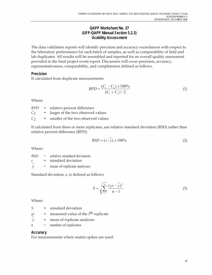
FORMER LOCKBOURNE AIR FORCE BASE LANDFILL SITE INVESTIGATION, QUALITY ASSURANCE PROJECT PLAN REVISION NUMBER: 0
REVISION DATE: DECEMBER 2008
99
QAPP Worksheet No. 37 (UFP-QAPP Manual Section 5.2.3)
Usability Assessment
The data validation reports will identify precision and accuracy exceedances with respect to the laboratory performance for each batch of samples, as well as comparability of field and lab duplicates. All results will be assembled and reported for an overall quality assessment provided in the final project event report. Discussion will cover precision, accuracy, representativeness, comparability, and completeness defined as follows.
PrecisionIf calculated from duplicate measurements:
2/)(
%100)(
21
21
CCxCCRPD
��
� (1)
Where:
RPD = relative percent difference C1 = larger of the two observed values C2 = smaller of the two observed values
If calculated from three or more replicates, use relative standard deviation (RSD) rather than relative percent difference (RPD):
%100)/( xysRSD � (2)
Where:
RSD = relative standard deviation s = standard deviation y = mean of replicate analyses
Standard deviation, s, is defined as follows:
1)( 2
1 ��
� � n
yyiSn
i
(3)
Where:
S = standard deviation yi = measured value of the ith replicate y = mean of replicate analyses n = number of replicates
AccuracyFor measurements where matrix spikes are used:

FORMER LOCKBOURNE AIR FORCE BASE LANDFILL SITE INVESTIGATION, QUALITY ASSURANCE PROJECT PLAN REVISION NUMBER: 0 REVISION DATE: DECEMBER 2008
100
QAPP Worksheet No. 37 (UFP-QAPP Manual Section 5.2.3)
Usability Assessment
�
� �
� ��
saCUSxR %100% (4)
Where:
%R = percent recovery S = measured concentration in spiked aliquot U = measured concentration in unspiked aliquot Csa = actual concentration of spike added
For situations in which a standard reference material (SRM) is used instead of or in addition to matrix spikes:
�
� �
��
sm
m
CCxR %100% (5)
Where:
%R = percent recovery Cm = measured concentration of SRM Csm = actual concentration of SRM
CompletenessCompleteness is a measure of the amount of valid data obtained compared with the amount that was expected to be obtained under correct, normal conditions. It is calculated for the aggregation of data for each analyte measured as a compound of concern for the project objectives. Valid data are data that are usable in the context of the project goals. Completeness is calculated and reported for each method, matrix, and analyte combination. The number of valid results divided by the number of possible individual analyte results, expressed as a percentage, determines the completeness of the data set. For completeness requirements, valid results are all results not qualified with an R-flag after a usability assessment has been performed. The goal for completeness, based on specific project goals, is 90 percent.
Completeness is defined as follows for all measurements:
��
���TVxC %100% (6)
Where:
%C = percent completeness V = number of measurements judged valid to be acceptable to meets project goals T = total number of measurements

FORMER LOCKBOURNE AIR FORCE BASE LANDFILL SITE INVESTIGATION, QUALITY ASSURANCE PROJECT PLAN REVISION NUMBER: 0
REVISION DATE: DECEMBER 2008
101
QAPP Worksheet No. 37 (UFP-QAPP Manual Section 5.2.3)
Usability Assessment
RepresentativenessRepresentativeness is the degree to which sample data accurately reflect the characteristics of a population of samples. It is achieved through a well-designed sampling program and by using standardized sampling strategies and techniques and analytical procedures. Factors that can affect representativeness include site homogeneity, sample homogeneity at a single point, and available information around which the sampling program is designed.
ComparabilityComparability is the confidence with which one data set can be compared to another. It is achieved by maintaining standard techniques and procedures for collecting and analyzing samples and reporting the analytical results in standard units. Results of QA split samples will provide additional information for assessing comparability of data among participating subcontractor laboratories.

102
References
Ellis Environmental Group (EEG). 2007. Remedial Investigation Report: Former Lockbourne Air Force Base Landfill. May.
Engineering Science, Inc. 1992. Final Site Investigation Report, Rickenbacker Air National Guard Base, Columbus, Ohio. May 1992.
Law Engineering and Environmental Services (Law). 1995. Final Site Investigation for Site Investigation –, Former Lockbourne Air Force Base Landfill, Rickenbacker Port Authority, Lockbourne, Ohio. November.
Program Management Company (PMC). 2000. Phase II Site Investigation Report, Former Lockbourne AFB Landfill, Lockbourne, OH.
CH2M HILL. 2008. Former Lockbourne AFB Landfill Site Investigation Work Plan. August 2008

Attachment 1 Laboratory Standard Operating Procedures

Laboratory SOPs are proprietanJ and confidential. They are provided upon request at the discretion of the Project Manager.
•
,
Attachment 2 Field Standard Operating Procedures

FIELD SOP-1
Test Pit Excavations
PurposeThis SOP provides guidance for investigating subsurface soils using test pit techniques to excavate soils and buried debris for visual characterization. Excavations must be conducted in a safe manner as identified by the contractor in respect to cave-in protection (e.g., sloping, benching, shoring, and/or shielding). The project Health and Safety Plan (HASP) identifies all CH2M HILL health and safety requirements.
Scope and Applicability Excavation inspection is by nature highly variable and, therefore, subject to change in response to what is observed. Refer to the specific requirements of the project in the Work Plan (WP) when using this SOP during field activities.
Example Equipment and Materials � Backhoe or similar equipment (to be operated by qualified subcontractor personnel
only) � Digital Camera � Field Log Book � Hand Tools (e.g., shovels)
Procedures and Guidelines Conduct test pitting at predetermined locations, using the following steps.
1. Obtain underground utility clearance in areas of test pits before any excavation begins. CH2M HILL also will notify the Ohio Utilities Protection Service (OUPS) (1-888-258-0808) at least 10 days before any field activities begin at the site for clearance of any public utilities areas on the base. For privately installed utilities, such as those at the airport, the appropriate property contact will be contacted and utilized to conduct a utility survey.
2. Perform full examination of backhoe for cut tires, hydraulic leaks, worn hoses, or any other maintenance issues prior to mobilization. Brush backhoe or trackhoe bucket clean of loose dirt before beginning excavation of test pit.
3. Dig pit in 3-foot-deep increments with a backhoe operated by experienced personnel. To increase the likelihood of finding buried material, excavate pits perpendicular to long axis of buried features, whenever possible.
MKE/SOP-1 TEST_PIT_EXCAVATIONS.DOC 1

FOP-10—TEST PIT EXCAVATION AND SOIL SAMPLING
4. Log and photograph test pits sufficient to document findings. Field logs for each test pit should include:
� Photograph log that includes descriptions of each test pit � Soil descriptions � Description of any debris or anomalies found, including at what depths � Dimensions of each test pit
5. Continue excavating until the test pit reaches desired target depth and dimensions, as identified in the WP.
6. When excavation is completed or terminated, handle excavated material as the WP
directs. Clear backhoe of any site material before it is taken off site.
Key Checks and Items � Excavate in 3-foot depth increments � Log observations of excavated soil, the excavation sidewalls, and debris.
MKE/SOP-1 TEST_PIT_EXCAVATIONS.DOC 2

FIELD SOP-2
Soil Screening with Flame Ionization Detector (FID)
PurposeThis technical practice provides general guidelines for calibration and use of a FID air monitoring device, such as a Photovac MicroFID or Thermo TVA 1000 PID /FID.
Scope and Applicability This technical practice provides a broad guideline for the field use of a FID. The FID is configured to measure volatile organic compounds (VOCs). For specific instructions, refer to manufacturer’s operations and maintenance manual.
Equipment / Materials � Operations manual � A FID with fully charged battery pack � A cylinder of calibration gas � A regulator for the calibration gas cylinder � A short length (as short as possible) of tubing to transfer calibration gas from cylinder to
FID
Procedures / Guidelines Only properly trained personnel shall use this instrument. For specific instructions, see operation manual.
Calibrating the FID Charge each FID every evening and calibrate it every morning following the manufacturer’s instructions. Record the make and model information, instrument serial number and calibration procedures in the field logbook.
Field Screening FID field screening data are to be recorded on a field form (e.g., a boring log) or in the field logbook. The FID can perform measurement of soil gases or fugitive emissions. The applicability of the field screening technique depends on the task.
WDC042870001.ZIP/KTM 1

AIR MONITORING WITH THE MULTIRAE INSTRUMENT
� Borehole Monitoring: The FID is to be used monitor the top of a boring to check for potentially hazardous atmospheres. This technique is applicable during monitor well installation, direct push soil sampling, and some hand augering.
� Sample Headspace Monitoring: Headspace monitoring is performed by placing a soil sample in an enclosed space for a set period and then monitoring the space above the sample. Headspace air monitoring can be performed if there is enough soil volume remaining after analytical soil sampling.
� Sample Screening: Sample screening is performed by placing the probe tip of the monitoring instrument near the location to be screened (e.g., a soil sample, water sample, unknown surface). The quality of the screening depends on the wind direction and distance of the monitoring instrument tip from the screened material or surface.
Key Checks / Items � Check battery. � Zero and calibrate. � Verify that sensor probe is working. � Recharge unit after use.
Preventive Maintenance If a FID instrument is not working, refer to the Operations Manual provided with the instrument or return to instrument to it’s point of origin for replacement.
WDC042870001.ZIP/KTM 2

�
������������� �������������������������������������������������� �����������
���
����������
������������� �������������������������������
��������������������� ����������������������������������������������������������������������������������������������
������������������������� �������������������������������������������������������������������������������������������������������������������������������������������������������� ����!������������!������������!���������������"���������������������������������������������������#�$��������������%��&�'���������� ��������������������� ������
�������������������������������• (���������������
• (������������������)��������������������
• ��������������%���������&��
• ������������������
• ����������������
�����������������������• *�����)���� �����������������������������)���������)�����!���������������������
• *�������%�������� �������������������&�
• +���
• ,���������������
• �������)���������������������
• (����)�������������!�����!�����������

�
������������� �������������������������������������������������� �����������
���
• -�����
• �������
• (����)�������������������)���������������������)��
• *�����)����������������������������
����� �������-����������.������'����������������������������������������������� ������/������������������������������)���������������������������������������������������0��� ������!����!�����������������������������������'�������������������)�����������������������������������������������������������'�����������������������������������������'���������������������������������������������� ������������������-����������'������������������������������������������������)��� ����
� ���������������������������!����������������-����������'���������������������������������������)!��������)���1�����������(�����������-���%*����������2&������������������������������������������������������������������3������������������������������������������������!����������������������4��
• 5�������������%�����������������������������&�
• ������������ ����3(!��������������������������������
• *�������������������������������������
• �����������������������������%������������������)��������3(&��
• (�����������������������������!��������)���
• (���������������������������
• .��������������!��������������!����������������6���������������7���������������������������5����������)�������������������8����!������������������������� �)��!���������83����
• *�)���������������������������
�����"����#������������ ������� ���*�������������������������)!�����������������������'��������������������������������������������������������������������������!���������������������������������'��������'������������������������������!��������������!����������������������'��������%����!�

�
������������� �������������������������������������������������� �����������
� �
� � ��������������� ��������3�������������������� ��������������������3(!����������������������������������'������������������������������'������ �������������
����������)������������������������������������)��������������������������������������������������������'���������4������������������������������'������������������������������������)�'���!�'�����'��������������������������������������������
$�#�������������#���������� �%���*��������������� ��������������!�����������������'���'�����������������������������������������������������!��������)�������!�������� ������������������������ �����������
�������������!������������������������������������������������������������������������ ������������������������������������������������������������������������������� ��'�������������������������
&��� ��'������$�����• /����������������������)�������)����������������)��
• 9�����0��������)������� ��������
• :�����������������������������������������������)��������� ��������
• "� ��'���������������������)������������������������������������������������
• .�� ���������������������������������������)��������������������

�
������������� �������������������������������������������������� �����������
���
����� ����()��������� ������� ����������5������7������;;;;;;;;;;;;;;;;;;��������7�����4�;;;;;;;;;;;;;;;;;;;;;;;;;;;;;;;;;;;;;;;;;;;�������:�����4�;;;;;;;;;;;;;;;;;;;;;;;;;;;;;;;;;;;;;;;;;;;;;;;;;;;;;;;;;;;;;;;;;;;;;;;;;;;;;��������%�����������5�����������������"����&4�;;;;;;;;;;;;;;;;;;;;;;;;;;;;;;;;;;;;;;;;;;;;;;;��/ ����%�����������5�����������������"����&4�;;;;;;;;;;;;;;;;;;;;;;;;;;;;;;;;;;;;;;;;;;;;;;;;���
Photo Number Date/Time Description Station Coordinates Notes
��� �� ���� ��� ���� ��� ���
� � � � � � � �
� � � � � � � �
� � � � � � � �
� � � � � � � �
� � � � � � � �
� � � � � � � �
� � � � � � � �
�

FIELD SOP-4
Global Positioning System (GPS) Survey
PurposeSOP-2 provides guidelines for collecting horizontal coordinates using global positioning systems (GPS) unit during field activities.
Scope and Applicability The method we describe for collecting horizontal coordinates applies to a Trimble� Pathfinder Pro XR, Pro XRS, or comparable GPS receiver. The level of accuracy following this procedure is submeter, which is important that the GPS survey be as accurate as possible, as these readings will be needed for accurate reporting.
Example Equipment and Materials � Trimble� Pathfinder Pro XR, Pro XRS, or comparable GPS receiver and compatible data-
logger
� Field Logbook
� Pin Flags
� Aerial Photograph or Map of Sampling Area
� Measuring Wheel
Procedures and Guidelines 1. Assemble and start GPS unit in accordance to manufacturer’s instructions.
2. Verify that GPS read-outs use Ohio State Plane North Coordinates.
3. Place the GPS antenna over the location where coordinates are to be collected. Record coordinates in field logbook and/or log coordinates into the GPS receiver. If locations are to be logged into the receiver, collect readings every 5 seconds for a period of 1 minute. (See manufacturer’s specific instructions on how to log positions). Name the data files recorded for each position using information from both the sample location identification and recorded date.
Download GPS data to a personal computer every 2 hours or at each new sampling site. If neither of these options for downloading data is available (i.e., when collecting samples from a boat), then record real-time readings of each coordinate in the field log book or appropriate field form.
RE ISION 0 SOP 4 GLO AL POSITIONING S STEM GPS SUR E .DOC OCTO ER 2007
1
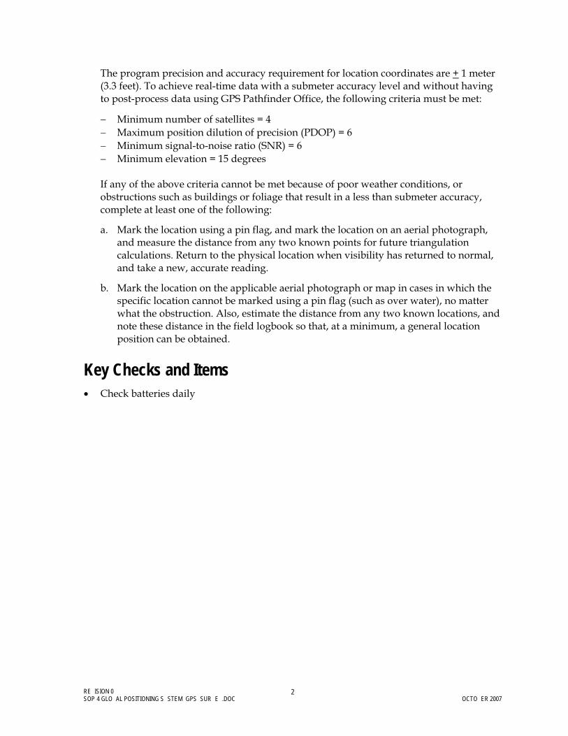
The program precision and accuracy requirement for location coordinates are + 1 meter (3.3 feet). To achieve real-time data with a submeter accuracy level and without having to post-process data using GPS Pathfinder Office, the following criteria must be met:
� Minimum number of satellites = 4 � Maximum position dilution of precision (PDOP) = 6 � Minimum signal-to-noise ratio (SNR) = 6 � Minimum elevation = 15 degrees If any of the above criteria cannot be met because of poor weather conditions, or obstructions such as buildings or foliage that result in a less than submeter accuracy, complete at least one of the following:
a. Mark the location using a pin flag, and mark the location on an aerial photograph, and measure the distance from any two known points for future triangulation calculations. Return to the physical location when visibility has returned to normal, and take a new, accurate reading.
b. Mark the location on the applicable aerial photograph or map in cases in which the specific location cannot be marked using a pin flag (such as over water), no matter what the obstruction. Also, estimate the distance from any two known locations, and note these distance in the field logbook so that, at a minimum, a general location position can be obtained.
Key Checks and Items � Check batteries daily
RE ISION 0 SOP 4 GLO AL POSITIONING S STEM GPS SUR E .DOC OCTO ER 2007
2
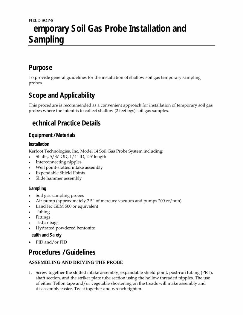
FIELD SOP-5
emporary Soil Gas Probe Installation and Sampling
PurposeTo provide general guidelines for the installation of shallow soil gas temporary sampling probes.
Scope and Applicability This procedure is recommended as a convenient approach for installation of temporary soil gas probes where the intent is to collect shallow (2 feet bgs) soil gas samples.
echnical Practice Details Equipment / Materials InstallationKerfoot Technologies, Inc. Model 14 Soil Gas Probe System including: � Shafts, 5/8;" OD, 1/4" ID, 2.5' length � Interconnecting nipples � Well point-slotted intake assembly � Expendable Shield Points � Slide hammer assembly
Sampling� Soil gas sampling probes � Air pump (approximately 2.5” of mercury vacuum and pumps 200 cc/min) � LandTec GEM 500 or equivalent � Tubing � Fittings � Tedlar bags � Hydrated powdered bentonite
ealth and Sa ety � PID and/or FID
Procedures / Guidelines ASSEMBLING AND DRIVING THE PROBE
1. Screw together the slotted intake assembly, expandable shield point, post-run tubing (PRT), shaft section, and the striker plate tube section using the hollow threaded nipples. The use of either Teflon tape and/or vegetable shortening on the treads will make assembly and disassembly easier. Twist together and wrench tighten.

2. Place the hammer sleeve over the striker plate tube section and then place the weighted slide hammer sleeve.
3. Drive the expendable shield point to 2 feet bgs into the ground by sliding the hammer up and down on the striker plate tube section. Note: you may need to screw additional rods together so that the slide hammer is about waist high, but no higher than mid-chest.
To steady the shafts while driving the assembly, use one hand to grasp the tube section below the striker plate. Use the other hand to lift and drop the slide hammer. An 8” to 12” strike distance is enough to drive the probe into the ground.
Periodically rotate the assembly clockwise to keep the threads tight. If necessary, use a wrench on the flats of the striker plate tube section. Add additional shaft sections to reach the desired depth. Leave about 6” of shaft above ground level for easy attachment and/or removal of shafts.
Operating Precautions:
� Keep hands away from the point of impact when driving the hammer. � Never lift the hammer so high that it becomes disengaged from the striker plate tube
section. � Do not thrust the hammer upward; lift it. An upward thrusting motion places excessive
stress on the joints and may result in loss of control of the hammer.
RETRIEVAL AND DISASSEMBLY OF SHAFTS
1. Rotate the shafts clockwise to make sure all joints are tight.
2. Remove the striker plate tube section.
3. Place the hammer sleeve and slide hammer over the shaft section protruding from the ground.
4. Screw the striker plate tube section back into place.
5. Using reverse hammering, hammer the shafts STRAIGHT UP and out of the ground. Exertion of any lateral force will damage the system.
6. Unscrew the shaft sections using to ½” open end wrenches.
7. At the ground surface, add bentonite powder to the annulus of the PRT protruding from the ground surface to ensure a good seal between the natural soil and the PRT.
CALIBRATION, PURGING AND SAMPLING
Calibration
Monitoring devices should be calibrated following the procedures spelled out in the user’s manuals and the calibration of each device should be included in the logbook, each time the device is calibrated. Calibration records should include the following:
� Date, time, individual performing the calibration � Ambient temperature � Serial number of device being calibrated � Serial or lot number of calibration gas being used � Pressure (as PSI) of calibration gas

� Calibration base reading and calibrated reading
After calibration is satisfactorily performed and recorded, the field survey can begin. Follow the manufacturer’s instructions on calibration frequency.
Purging and Sampling
1. Using a small battery operated air pump (approximately 2.5” of mercury vacuum and pumps 200 cc/min), purge 3 volumes of air from the PRT
2. Connect a Tedlar bag to the output of the air pump and allow the Tedlar bag to fill to approximately 80%.
3. Disconnect Tedlar bag from the pump output and screen the contents using a LandTec GEM 500 or equivalent.
4. The log book should record the following at each sampling location:
Time (military notation) Sample number Location (approximate description - i.e., street names) Sampling depth Monitoring device readings % CH4, % CO2, Bulk VOCs
� CH4 as a percentage of LEL
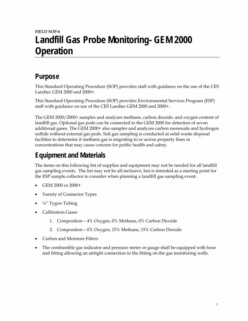
FIELD SOP-6
Landfill Gas Probe Monitoring- GEM 2000 Operation
PurposeThis Standard Operating Procedure (SOP) provides staff with guidance on the use of the CES Landtec GEM 2000 and 2000+.
This Standard Operating Procedure (SOP) provides Environmental Services Program (ESP) staff with guidance on use of the CES Landtec GEM 2000 and 2000+. The GEM 2000/2000+ samples and analyzes methane, carbon dioxide, and oxygen content of landfill gas. Optional gas pods can be connected to the GEM 2000 for detection of seven additional gases. The GEM 2000+ also samples and analyzes carbon monoxide and hydrogen sulfide without external gas pods. Soil gas sampling is conducted at solid waste disposal facilities to determine if methane gas is migrating to or across property lines in concentrations that may cause concern for public health and safety.
Equipment and MaterialsThe items on this following list of supplies and equipment may not be needed for all landfill gas sampling events. The list may not be all-inclusive, but is intended as a starting point for the ESP sample collector to consider when planning a landfill gas sampling event.
� GEM 2000 or 2000+
� Variety of Connector Types
� ¼” Tygon Tubing
� Calibration Gases
1. Composition – 4% Oxygen, 0% Methane, 0% Carbon Dioxide
2. Composition – 0% Oxygen, 15% Methane, 15% Carbon Dioxide
� Carbon and Moisture Filters
� The combustible gas indicator and pressure meter or gauge shall be equipped with hose and fitting allowing an airtight connection to the fitting on the gas monitoring wells.
1

GEM 2000 LAND ILL GAS PRO E MONITORING
Procedures and Guidelines General Operation 1. Turn on the instrument by holding down the On/Off key. The instrument will automatically perform a clean air purge and warm-up self test. During the selftest, check the bottom of the screen for any warning or error displays (i.e., battery charge low). Be sure the clean air purge is performed away from any source of contaminating gas such as landfill gas wells or auto exhaust. 2. After the self-test, check the clean air purge for return of appropriate readings (20% oxygen, 0% methane and 0% carbon dioxide). Also check the battery and memory gauges at the right of the screen for adequate charge level and memory space. 3. Non-extraction wells are usually called gas probes or gas monitoring wells. The GEM 2000/2000+ may be operated as a Landfill Gas Analyzer for probes or a Gas Extraction Monitor. Be sure that the instrument is set to the correct Mode of Operation; this option is found in the ‘ ’ Menu. The Landfill Gas Analyzer mode is employed when checking peripheral landfill monitoring wells for methane migration. The Gas Extraction Monitor mode is used for measuring output from gas extraction wells. 4. Perform field calibration immediately prior to each sampling event. See below for field calibration procedure. 5. The instrument is now ready to take readings. Readings are measured and reported as percent by volume of gas inside the well. Readings are most accurate when the well is equipped with a sampling port to seal the connection between the well and the instrument. 6. Connect appropriate sized tubing and connectors for a tight seal. Include a moisture filter along the tubing, between the well and the GEM, to prevent moisture entering the instrument. The filter is connected externally with two sections of tubing. 7. A carbon filter may be necessary to eliminate excess hydrocarbon gases from interfering with the methane reading. The carbon filter is connected externally with two sections of tubing. A carbon filter should be applied when readings exceed 50% methane by volume, or other conditions indicate cross-gas effects. New carbon filters must be conditioned by pumping methane-containing gas through the filter until readings stabilize. 8. Readings may be stored on the GEM. The instrument’s memory is maintained by a battery back-up system; however, the memory should not be used as permanent storage for data.
Field Calibration Procedures 1. Field calibration should be performed immediately prior to each sampling event, using calibration gases close to the expected range of measurement. If more than one landfill is sampled in a day, the instrument should be calibrated prior to sampling each landfill.
2

GEM 2000 LAND ILL GAS PRO E MONITORING
2. Press ‘ ’ for Menu. Use up ‘ ’ or down ‘ ’ keys to scroll to “Field Calibration”, then press Enter ‘�’. 3. Press ‘ ’ Edit Target Concentration, use enter ‘�’ to move to desired field. Manually enter the concentrations of each calibration gas. Press ‘�’ to complete. 4. Connect the calibration gas bottle with 0% methane to the sample inlet port. Open gas regulator valve and allow gas to flow for approximately 30 seconds. Bring up the Calibration Menu using ‘�’. Choose Zero Channels and press ‘�’. Then choose Zero Methane and press ‘�’. If calibration was successful you should see the message “User Zero Complete.” 5. Connect the calibration gas bottle with 0% oxygen. Open gas regulator valve and allow gas to flow for approximately 30 seconds. Bring up the Calibration Menu using ‘�’. Choose Zero Channels, then Zero Oxygen. If calibration was successful you should see the message “User Zero Complete.” 6. Using the 0% oxygen bottle, allow gas to flow for approximately 30 seconds. Press ‘�’ to return to the Calibration Menu and choose Span Channels, then choose Span Methane. If calibration was successful you should see the message “Calibration Complete.” 7. With the 0% oxygen bottle connected and gas still flowing, press ‘�’ to return to the Calibration Menu and choose Span Channels, then choose Span Carbon Dioxide. If calibration was successful you should see the message “Calibration Complete.” Close the gas regulator valve and remove the 0% oxygen bottle. 8. Connect the calibration gas bottle containing 4% oxygen, open gas regulator valve and allow gas to flow for approximately 30 seconds. Press ‘�’ to return to the Calibration Menu and choose Span Channels, then choose Span Oxygen. If calibration was successful you should see the message “Calibration Complete.” Close the gas regulator valve and remove the 4% oxygen bottle. 9. Perform clean air purge. Connect sampling tubes to a bottle of known gas concentration, press the pump key ‘ ’, open gas regulator valve and allow gas to flow for approximately 30 seconds to check the calibration.
Taking a reading at a well with a preset identification number (ID) 1. SWMP designates preset well ID numbers that are loaded onto the GEM 2000/2000+ at the beginning of each sampling season. Use of these ID numbers facilitates download and transfer of the data between ESP and SWMP. 2. Select ‘ ’ Next ID and choose the desired ID. Press ‘�’ to select the ID; an automatic purge begins. Be sure sampling tubes are disconnected from well prior to selecting the ID and beginning the purge.

GEM 2000 LAND ILL GAS PRO E MONITORING
3. After the purge is finished, connect the sampling tube to the selected well. Begin reading by pressing the pump key ‘ ’. Wells with preset ID will also have a pre-programmed run time for the pump. The pump will automatically shut off at the end of this period. ESP samples each well for 90 seconds. 4. Press the enter/store key ‘�’ to store the reading, and record in field notebook.
Taking a reading at a well with no preset ID 1. Be sure sampling tubes are disconnected from well. Select ‘ ’ Next ID and choose ‘ ’ Select No ID. Press ‘�’ to begin clean air purge. Connect the sample tubes to the well. Press ‘ ’ to start the pump. 2. The timer will begin counting the time the pump has run; after 90 seconds press ‘ ’ to stop the pump. 3. Press ‘�’ to store the reading. A virtual keyboard will appear to enter ID information for the well. Record reading in field notebook.
DataField CS Software 1. To load ID information created by SWMP onto the GEM 2000/2000+, connect the RS-232 download cable to an open COM port on your computer. Connect the other end of the RS-232 download cable to the GEM 2000/2000+ data port. DataField CS has the ability to automatically scan the different COM ports on your computer to find where the instrument is connected. 2. Turn the instrument on; wait for the self-test function to finish. The Gas Readings screen will display; if not, then turn off the GEM and re-start the instrument. The GEM must be in the Gas Reading screen in order to establish communications. 3. Once the instrument is in the proper communications mode, click on the Start menu, then All Programs menu. Scroll to DataField and then DataField CS to initialize the software. 4. Once DataField CS establishes communication with the instrument, the main software screen will appear. Seven main categories (buttons) are listed down the left side of the screen: ID Functions, Readings, Comments, Site Questions, Clear Memory, Instrument Settings and Resource Links. Clicking on any one of the buttons will take the user to that functionality of the application. 5. From the opening screen select the ‘ID’ button. Selecting the ‘Load from File’ button will allow a previously created file to be loaded from the computer disk drive. ‘Add ID’ button is used for the creation of a new ID or multiple IDs that may be sent to the instrument or saved to a new file for later use. Once all the IDs have been entered, click ‘Save File’ button to save the ID data to a file or ‘Send to Instrument’ button if data is to be uploaded to an instrument for field sampling.
4

GEM 2000 LAND ILL GAS PRO E MONITORING
6. The Readings screen provides the capability to download, upload, view, save data to a file and delete individual or multiple readings from a data set. Click on the ‘Readings’ button to open the appropriate screen. Click on the ‘Load from Instrument’ button. 7. See the GEM User’s Manual for more detailed information on software.
QUALITY ASSURANCE/QUALITY CONTROL Field calibration should be performed immediately prior to each sampling event, using calibration gases close to the expected range of measurement. If more than one landfill is sampled in a day, the instrument should be calibrated prior to sampling each landfill.
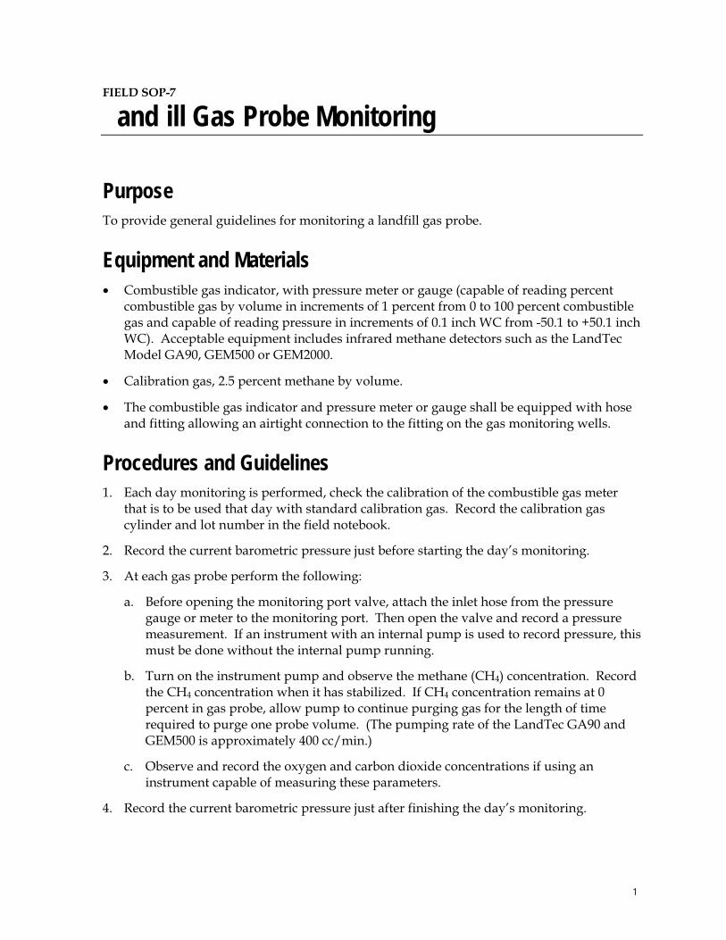
FIELD SOP-7
and ill Gas Probe Monitoring
PurposeTo provide general guidelines for monitoring a landfill gas probe.
Equipment and Materials� Combustible gas indicator, with pressure meter or gauge (capable of reading percent
combustible gas by volume in increments of 1 percent from 0 to 100 percent combustible gas and capable of reading pressure in increments of 0.1 inch WC from -50.1 to +50.1 inch WC). Acceptable equipment includes infrared methane detectors such as the LandTec Model GA90, GEM500 or GEM2000.
� Calibration gas, 2.5 percent methane by volume.
� The combustible gas indicator and pressure meter or gauge shall be equipped with hose and fitting allowing an airtight connection to the fitting on the gas monitoring wells.
Procedures and Guidelines 1. Each day monitoring is performed, check the calibration of the combustible gas meter
that is to be used that day with standard calibration gas. Record the calibration gas cylinder and lot number in the field notebook.
2. Record the current barometric pressure just before starting the day’s monitoring.
3. At each gas probe perform the following:
a. Before opening the monitoring port valve, attach the inlet hose from the pressure gauge or meter to the monitoring port. Then open the valve and record a pressure measurement. If an instrument with an internal pump is used to record pressure, this must be done without the internal pump running.
b. Turn on the instrument pump and observe the methane (CH4) concentration. Record the CH4 concentration when it has stabilized. If CH4 concentration remains at 0 percent in gas probe, allow pump to continue purging gas for the length of time required to purge one probe volume. (The pumping rate of the LandTec GA90 and GEM500 is approximately 400 cc/min.)
c. Observe and record the oxygen and carbon dioxide concentrations if using an instrument capable of measuring these parameters.
4. Record the current barometric pressure just after finishing the day’s monitoring.
1

LAND ILL GAS PRO E MONITORING
5. Record name(s) of monitoring personnel, date, weather (precipitation conditions and approximate ambient temperature), and the model and serial number of the monitoring instrument(s) in the field notebook.
2

FIELD SOP-8
Low-Flow Seep Water Sampling
Purpose and Scope This procedure presents general guidelines for the collection of water samples from monitoring points using low-flow purging and sampling procedures. Operations manuals should be consulted for specific calibration and operating procedures.
Equipment and Materials � Peristaltic pump � Flow-through cell with inlet/outlet ports for purged water and watertight ports for each
probe � Meters to monitor water quality parameters (e.g., pH, specific conductance, turbidity,
dissolved oxygen, oxidation-reduction potential (ORP), and temperature) (e.g., Horiba® U-22 or similar)
� Water-level indicator � In-line disposable 0.45� filters (QED® FF8100 or equivalent) � Adjustable-rate, positive-displacement pump, submersible, or peristaltic pump � Disposable polyethylene tubing � Plastic sheeting � Calibrated bucket or other container and watch with second indicator to determine flow
rate � Sample containers � Shipping supplies (labels, coolers, and ice) � Field logbook
Procedures and Guidelines A. Setup and Purging
1. Instruments are calibrated according to manufacturer's instructions and information such as make/model and calibration and use specifications are recorded in the field logbook.
2. The location number, site, date, and condition are recorded in the field logbook.
3. Plastic sheeting is placed on the ground, and all equipment to be used in sampling will be placed only on the plastic sheeting until after the sampling has been completed. To avoid cross-contamination, do not let any downhole equipment touch the ground.
SOP SEEP WATER SAMPLING APRIL 2008
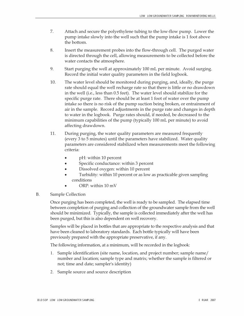
LOW LOW GROUNDWATER SAMPLING ROM MONITORING WELLS
7. Attach and secure the polyethylene tubing to the low-flow pump. Lower the pump intake slowly into the well such that the pump intake is 1 foot above the bottom.
8. Insert the measurement probes into the flow-through cell. The purged water is directed through the cell, allowing measurements to be collected before the water contacts the atmosphere.
9. Start purging the well at approximately 100 mL per minute. Avoid surging. Record the initial water quality parameters in the field logbook.
10. The water level should be monitored during purging, and, ideally, the purge rate should equal the well recharge rate so that there is little or no drawdown in the well (i.e., less than 0.5 feet). The water level should stabilize for the specific purge rate. There should be at least 1 foot of water over the pump intake so there is no risk of the pump suction being broken, or entrainment of air in the sample. Record adjustments in the purge rate and changes in depth to water in the logbook. Purge rates should, if needed, be decreased to the minimum capabilities of the pump (typically 100 mL per minute) to avoid affecting drawdown.
11. During purging, the water quality parameters are measured frequently (every 3 to 5 minutes) until the parameters have stabilized. Water quality parameters are considered stabilized when measurements meet the following criteria:
� pH: within 10 percent � Specific conductance: within 3 percent � Dissolved oxygen: within 10 percent � Turbidity: within 10 percent or as low as practicable given sampling
conditions � ORP: within 10 mV
B. Sample Collection
Once purging has been completed, the well is ready to be sampled. The elapsed time between completion of purging and collection of the groundwater sample from the well should be minimized. Typically, the sample is collected immediately after the well has been purged, but this is also dependent on well recovery.
Samples will be placed in bottles that are appropriate to the respective analysis and that have been cleaned to laboratory standards. Each bottle typically will have been previously prepared with the appropriate preservative, if any.
The following information, at a minimum, will be recorded in the logbook:
�� Sample identification (site name, location, and project number; sample name/ number and location; sample type and matrix; whether the sample is filtered or not; time and date; sampler's identity)
�� Sample source and source description
IELD SOP LOW LOW GROUNDWATER SAMPLING E RUAR 2007
LOW LOW GROUNDWATER SAMPLING ROM MONITORING WELLS
�� Field observations and measurements (appearance, volatile screening, field chemistry, sampling method), volume of water purged prior to sampling, number of well volumes purged, and field parameter measurements
� Sample disposition (preservatives added; laboratory sent to, date and time sent; laboratory sample number, chain-of-custody number, sample bottle lot number)
The steps to be followed for sample collection are as follows:
1. The cap is removed from the sample bottle, and the bottle is tilted slightly.
2. The sample is slowly discharged from the pump so that it runs down the inside of the sample bottle with a minimum of splashing. The pumping rate should be reduced to approximately 100 ml per minute when sampling VOCs.
3. Samples collected for metals analysis will be field filtered before transfer to the sample bottle. Filtration must occur in the field immediately upon collection. The recommended method is through the use of a disposable in-line filtration module (0.45-micron filter) using the pressure provided by the pumping device for its operation.
4. Samples for analysis for volatile organic compounds should be collected first, if such samples are required.
5. Adequate space is left in the bottle to allow for expansion, except for VOC vials, which are filled to overflowing and capped.
6. The bottle is capped and then labeled clearly and carefully.
C. Additional remarks
1. If the location goes dry during purging, wait until it recovers sufficiently to remove the required volumes to sample all parameters. It may be necessary to return periodically to the location but a particular sample (e.g., large amber bottles for semivolatile analysis) should be filled at one time rather than over the course of two or more visits to the well.
D. Duplicate and split-samples will be collected according to the procedures and guidelines provided above.
IELD SOP LOW LOW GROUNDWATER SAMPLING E RUAR 2007

LOW LOW GROUNDWATER SAMPLING ROM MONITORING WELLS
IELD SOP LOW LOW GROUNDWATER SAMPLING E RUAR 2007
AttachmentsNone.
Key Checks and Preventative Maintenance � The drawdown in the well should be minimized as much as possible (preferably no
more than 0.5 to 1 foot) so that natural water-flow conditions are maintained as closely as possible.
� Stirring up of sediment should be avoided so that turbidity containing adsorbed chemicals is not suspended in the well and taken in by the pump.
� Keep the working space clean with plastic sheeting and good housekeeping.
� Maintain field equipment in accordance with the manufacturer’s recommendations. This will include, but is not limited to:
� Inspect sampling pump regularly and replace as warranted � Inspect quick-connects regularly and replace as warranted � Verify battery charge, calibration, and proper working order of field measurement
equipment prior to initial mobilization and daily during field efforts

FIELD SOP-9
Field Filtering ater Samples
PurposeThis technical practice provides general guidelines for field filtering of water samples for dissolved metals analysis.
Scope and Applicability This technical practice provides guidelines on equipment, materials, and procedures to field filter water samples for dissolved metals analysis.
Refer to the specific requirements of the project in the Work Plan/Sampling Plan (WP/SP) and Quality Assurance Project Plan (QAPP) when using this SOP during field activities.
E ample Equipment / Materials � Deionized water
� Geopump
� C-Flex� tubing
� Teflon® tubing
� 0.45 micron in-line filter cartridge
Procedures / Guidelines Filtering Samples at ime o Collection 1. Collect a water sample for filtration in a clean sampling device.
2. Insert one end of a length of Teflon tubing into the sampling device.
3. Insert other end of Teflon tubing into one end of C-Flex tubing (already installed in pump head).
4. Insert filter capsule into other end of C-Flex tubing.
5. Filter sample into a pre-cleaned bottle preserved with nitric acid.
6. Dispose of filter and tubing as investigation-derived waste.
SOP W S . APRIL 2008 1

Filtering Samples a ter All Samples Are Collected 1. Collect samples in pre-cleaned containers that do not contain preservative.
2. Insert short length of Teflon tubing into the sample.
3. Insert other end of Teflon tubing into one end of C-Flex tubing (already installed in pump head).
4. Insert filter capsule into other end of C-Flex tubing.
5. Turn on Geopump so that the sample flows through tubing, through filter, and into sample container.
6. Filter sample into pre-cleaned bottle as specified in the WP/SP and QAPP.
7. Dispose of filter and tubing as investigation-derived waste.
Key Checks / Items � Use pre-cleaned containers.
� Use new filters and tubing for each sample.
SOP W S . APRIL 2008 2

SOP 10 IELD DECONTAMINATION PROCEDURES.DOC APRIL 2008
FIELD SOP-10
Field Decontamination Procedures
PurposeThis technical practice provides guidelines for decontamination groundwater investigation equipment, sampling equipment, and monitoring equipment used in potentially contaminated environments.
Scope and Applicability This technical practice provides a description of decontamination procedures. Refer to the specific requirements of the project in the Work Plan/Sampling Plan (WP/SP) and the Quality Assurance Project Plan when using this SOP during field activities.
Equipment / Materials � Emergency eyewash.
� Distilled water.
� Alconox (or other detergent) and potable water solution.
� Large plastic pails, totes, or tubs for detergent and water; scrub brushes; squirt bottles for detergent and water; and plastic bags and sheets.
� DOT approved 55-gallon drum or poly tank for collection of any decontamination solvents that are used.
Procedures / Guidelines Sampling Equipment DecontaminationPersonnel wearing proper safety protection shall decontaminate all sampling equipment.
The following procedures will be utilized:
1. Wash all equipment surfaces that contacted the potentially contaminated soil or water with detergent solution, using a brush as needed to remove particulate matter and surface films.
2. Rinse with potable tap water.
3. Rinse with distilled water and air dry.
4. Wrap equipment with aluminum foil, if appropriate, to reduce the need for subsequent
SOP 10 IELD DECONTAMINATION PROCEDURES.DOC APRIL 2008
cleaning if equipment is to be stored or transported.
5. Collect any decontamination fluids used in a DOT-approved 55-gallon drum or other approved temporary storage container and disposal. Review Work Plan/Sampling Plan (WP/SP) for information regarding disposal of rinse waters. Follow disposal practices specified in the WP/SP.
Monitoring Equipment Decontamination Monitoring equipment shall be decontaminated as follows:
1. Wipe all surfaces that had possible contact with contaminated materials with a paper towel wet with detergent solution. Then wipe three times with a towel wet with distilled water.
2. Dispose of all used paper towels in a DOT-approved 55-gallon drum or other approved temporary storage container.
Sample Container Decontamination The outer surface of sample containers filled in the field must be decontaminated before being either packed for shipment or handled by personnel without dermal hand protection.
1. Wipe container with a paper towel dampened with detergent solution after containers have been sealed.
2. Then wipe container with a paper towel dampened with potable water.
3. Dispose of all used paper towels in a DOT-approved 55-gallon drum or other approved temporary storage container.
Key Checks / Items � Clean sampling equipment, with solutions of detergent and distilled water.
� Clean monitoring equipment with solutions of detergent and distilled water.
� Clean sample containers with solutions of detergent and potable water before relinquishing them to anyone.
� Document any deviations from above procedure.

FIELD SOP-11
Sample andling and Shipping Custody Procedures
PurposeThis technical practice explains the procedures for packaging samples for shipment to the laboratory and shipping custody procedures.
Scope and Applicability This technical practice is applicable to packaging, shipping, and shipping custody requirements for all analytical samples sent to a laboratory for testing.
Refer to the specific requirements of the project in the Work Plan/Sampling Plan (WP/SP) when using this SOP during field activities.
E ample Equipment / Materials� Coolers for shipping
� Tape (strapping tape, duct tape, wide clear tape)
� Mailing label with laboratory address, phone number, and return address
� Pre-formed polyfoam wrap, bubble wrap, or other temperature and shock insulating material
� Chain-of-custody (COC) forms
� Airbill
� Ice
� Plastic zip-lock bags
� Custody seals
Procedures / GuidelinesSamples shall be under COC protocols at all times. COC protocols shall include restricted access to all sample containers, and samples before, during, and after sample collection. Sampling materials that are not in the direct possession of a project team member shall be locked or sealed
SOP 11 S H C C S . APRIL 2008 1
in a secure area to prevent tampering. After the samples have been collected, the team shall return to a clean facility and proceed with sample shipment preparations. Samples with analyses that have short holding times shall be shipped with a minimum of delay, preferable the same day as collection. The steps for shipping samples are as follows:
1. If the shipping cooler is equipped with drain holes, tape holes shut with duct tape, inside and out.
2. Place mailing label on lid of cooler, and cover with clear protective tape.
3. Fill bottom of cooler with preformed poly foam wrap, bubble wrap, or other temperature and shock insulating material.
4. Examine each sample bottle. Each sample container should be decontaminated (technical practice Field SOP Field Equipment Decontamination). Make sure that each bottle is appropriately labeled with the sample date and time, analysis, and sampler's initials and that the bottle caps are securely fastened. Cover the label with clear protective tape, completely encircling the bottle.
5. Place each bottle or group of bottles inside plastic zip-lock bags and seal bags.
6. Arrange bottles inside the cooler so they do not touch.
7. List all samples packaged inside cooler on the electronic COC (see Field SOP Field Sampling Documentation) and record sample numbers and COC number on a field sample log.
8. If ice is required to preserve the samples at 4O C, ice should be packaged in double zip-lock bags and placed on and around the sample containers (especially on volatile organic compound vials).
9. Fill remaining spaces with packing material to prevent contents from shifting during shipping.
10. Make sure all pertinent fields on the COC are filled out. The field team leader or lead sampler shall sign the COC and record the time and date.
11. Complete the shipping airbill. If appropriate, record the airbill tracking number on the COC form. Attach airbill or airbill receipt to the top of the sample cooler.
12. Separate the copies of the COC. Seal laboratory’s copy in a zip-lock bag and tape zip-lock bag to the inside of the cooler lid.
13. Close and secure cooler lid.
14. Carefully peel custody seals from backings and place intact over lid openings, one in front and one in back. Cover seals with clear protection tape.
15. Tape cooler shut on both ends, making several complete revolutions with strapping tape. Do not cover custody seals, mailing label, or air bill with strapping tape.
16. Cooler is ready to be relinquished to the shipping carrier. Keep data user’s copies of COC
SOP 11 S H C C S . APRIL 2008 2
SOP 11 S H C C S . APRIL 2008
and shipper’s copy of the airbill together. Put receipts in a binder for storage.
17. The sample data manager shall call or fax COC information to the laboratory each day that samples are shipped. The laboratory shall be provided with the airbill numbers, number of coolers, and number of samples.
Key Checks / Items� Seal cooler drain holes.
� Package bottles in such a way to protect from breakage.
� Add sufficient ice (double bagged) to keep samples cool during shipment.
� Sign and date the completed COC form, and place laboratory’s copies inside the cooler.
� Tape the lid shut and custody seal the cooler.
� Shipping label and airbill must be on cooler.
� Keep the user’s copy of the COC and airbill together. Each day’s paperwork is to be filed in a secure location.

FIE D S P
Field Documentation
ApplicabilityThis procedure defines the general guidelines for documenting field activities. Proper documentation of field activities and sample control is necessary to ensure defensibility of data and to verify the quality of work performed as a part of the field activities. This SOP will deal with field forms and field logbooks.
esponsibilityField Team Leader – Responsible for assigning each field team a field logbook with a unique identification name, identifying the individuals responsible for each log, determining the storage area for log books, and daily QA/QC of field logbooks.
Sample Processing Team – Responsible for giving field team appropriate field forms for day’s activities, storage of completed field logs, and daily QA/QC of field forms.
Field Team Member – Responsible for signing in and out field logbooks each day, making copies of each day’s field notes for Field Team Leader to review, turning in completed copies of field forms to Sample Processing Team along with samples.
E ample Equipment and Materials � Field Logbooks � Field forms (i.e. sample logs, soil boring logs) � Indelible black pen
ProceduresField log books and other logs associated with this site investigation are legal documents and, as such, must be prepared following specific procedures and must contain required information to ensure their integrity and legitimacy. This portion of the SOP describes the basic requirements for field logbook entries and field forms.
General Procedures or Completing Field ogbooks ogbook Set up
� Each log book will contain the Company name and address, project name, project manager’s name, and any pertinent phone numbers in the front of the logbook;
� Each page in the logbook will be sequentially numbered; � The top of each page will contain the page number, project name and number, and date.
RE ISION 0 SOP 12 IELD DOCUMENTATION.DOC 1

2
Format or Each Page� All lines of all pages should be used to prevent later additions of text; � Any line not used should be completely marked through ; � Any page(s) not used should be marked through and noted as “Void” or “Intentionally
Left Blank”. Author will also sign and date page; � Information will be recorded directly into the field logbook during the work activity; � Only information relevant to the subject project will be added in the field logbook; � Entries will be made chronologically by time using military time; � The final page of each day’s notes will include the author’s signature as will as the date.
Errors in Field ogbook � If errors are made, a single line shall be made through the error and the correct
information made above or adjacent to the error; � The author will initial and date the lined through error.
Field Form Completion All fields on each form will be filled out completely and submitted on a daily basis to the Sample Processing Team to input and archive.

Attachment 3 Example Chain of Custody and Custody Seal

Rev. 3/2006 Chain of Custody Page _______ of _______ 1230 Lange Court, Baraboo, WI 53913
608-356-2760 Fax 608-356-2766 www.ctlaboratories.com
Company: Project Contact: Telephone: Project Name: Project Number: Project Location: Sampled By:
Mail Report To: Company: Address: City/State/Zip: Invoice To: Company: Address: City/State/Zip: Regulatory Program:
UST RCRA SDWA NPDES Solid Waste Other __________
Turnaround Time Normal RUSH*
Date Needed _______________
*Notify Lab prior to sending in RUSH samples. Surcharges:
24 hr 200% 2-3 days 100% 4-9 days 50%, subject to change without notice.
Lab Use Only
Place Header Sticker Here:
PO No.
ANALYSES REQUESTED Client Special Instructions: Landfill License Number:
* Preservation Code A=None B=HCL C=H2SO4 D=HNO3 E=Encore F=Methanol G=NaOH O=Other ___________
Collection Filte
red?
Y/N
**M
atri
x:
Tota
l # o
f Con
tain
ers
Pres
erva
tion*
Date Time Grab/ Comp Sample ID Description Fill in Spaces with Bottles per Test Lab ID #
Relinquished By: Date/Time Relinquished By: Date/Time
Received by: Date/Time Received for Laboratory by: Date/Time
Ice Present Yes No
Temperature ________________ Cooler # ____________________
**Matrix
S–Soil A–Air Sl–Sludge M–Misc Waste GW–Groundwater SW–Surface Water WW–Wastewater DW–Drinking Water
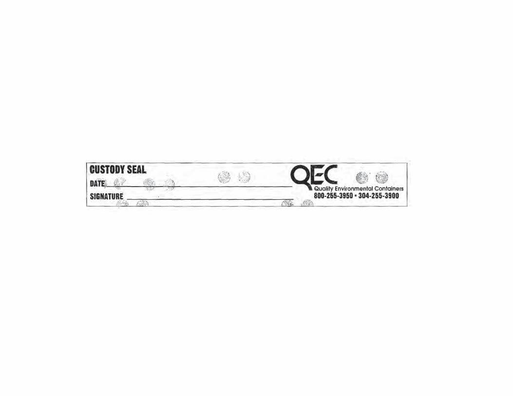

Figures

��������������������
����
�������
���������������������
������
���������������
���������������
HU-A
UMU-A
UMU-BHU-B
UMU-CHU-B-4
HU-A-3
UMU-C-3
HU-A-4
UMU-B-1
HU-A-1
UMU-C-1
HU-A-2
UMU-B-3
UMU-A-1
UMU-B-2
UMU-A-2
UMU-A-3
HU-B-2
HU-B-1
UMU-C-2
HU-B-3
$ 0 600 1,200
Feet
Figure 2-1Trenching/EM-31 Reconnaissance Survey LocationsSite Investigation Work PlanFormer Lockbourne Air Force Base
LEGEND
Proposed Trench/Test Pit Locations
Heavily Used Area
Unused to Moderately Used Area (UMU-A-3)
���������� Approximate Proposed Geophysical Investigation Area
EM 31 Data
50
45
(Millisiemens
40
35
/ Meter)
30
25
<25
HU-A-1
UMU-A-3
EM 31 Data Collected During 1995 Site Investigation

ED
ED
ED
ED
ED
ED
ED
ED
ED
ED
ED
ED
ED
ED
ED
ED
ED
ED
ED
ED
$ 0 600 1,200
Feet
Figure 2-2 Methane Sampling LocationsSite Investigation Work PlanFormer Lockbourne Air Force Base
LEGEND
ED Methane Sampling Locations
Approximate Work Area
EM 31 Data
50
45
(Millisiemens
40
35
/ Meter)
30
25
<25EM 31 Data Collected During 1995 Site Investigation

@A
@A
@A
@A
@A@A
@A
West Ditch
East D
itch
LCK-SW5
LCKSP-1
LCK-SW3
LCKSW-4
LCKSP-2
LCKSP-3
$ 0 600 1,200
Feet
Figure 2-3Seep Water Sampling LocationsSite Investigation Work PlanFormer Lockbourne Air Force Base
LEGEND
@A Seep Water Sampling Location (West Ditch)
@A Seep Water Sampling Location (East Ditch)
Approximate Work Area
Storm Water Ditch
EM 31 Data
50
45
(Millisiemens
40
35
/ Meter)
30
25
<25
EM 31 Data Collected During 1995 Site Investigation


