
Frankfurt (Germany), 6-9 June 2011
Pyeongik Hwang
School of Electrical Engineering
Seoul National University
Korea
Hwang – Korea – RIF Session 4a – 0324
A control method of distributed generators in smart distribution system
considering system loss and voltage
Frankfurt (Germany), 6-9 June 2011
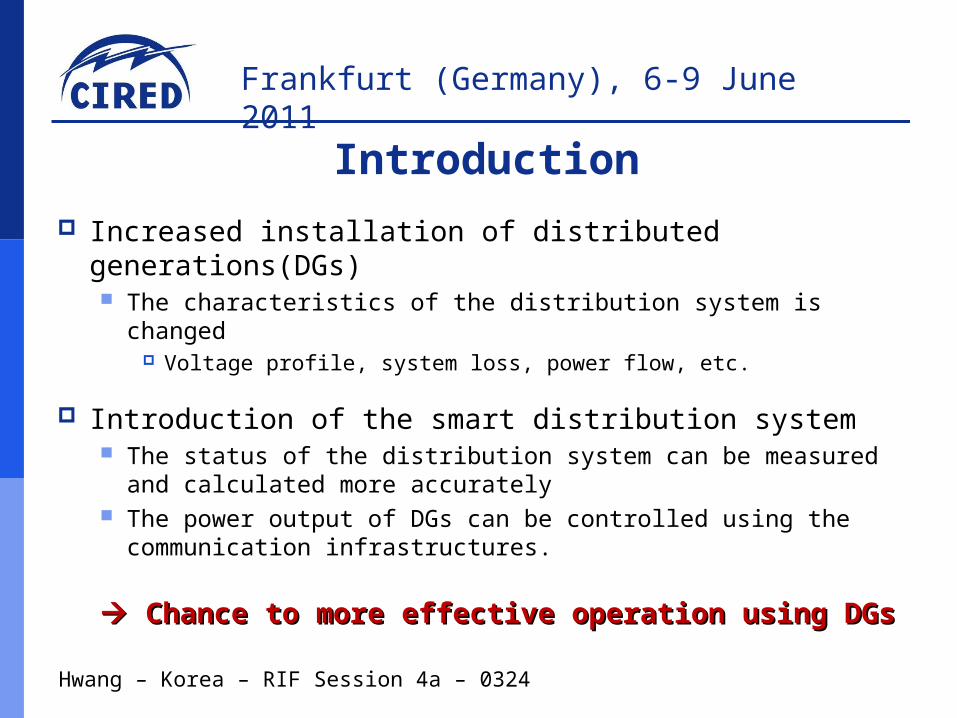
Increased installation of distributed generations(DGs) The characteristics of the distribution system is changed
Voltage profile, system loss, power flow, etc.
Introduction of the smart distribution system The status of the distribution system can be measured and
calculated more accurately The power output of DGs can be controlled using the
communication infrastructures.
Chance to more effective operation using DGsChance to more effective operation using DGs
Hwang – Korea – RIF Session 4a – 0324
Introduction
Frankfurt (Germany), 6-9 June 2011
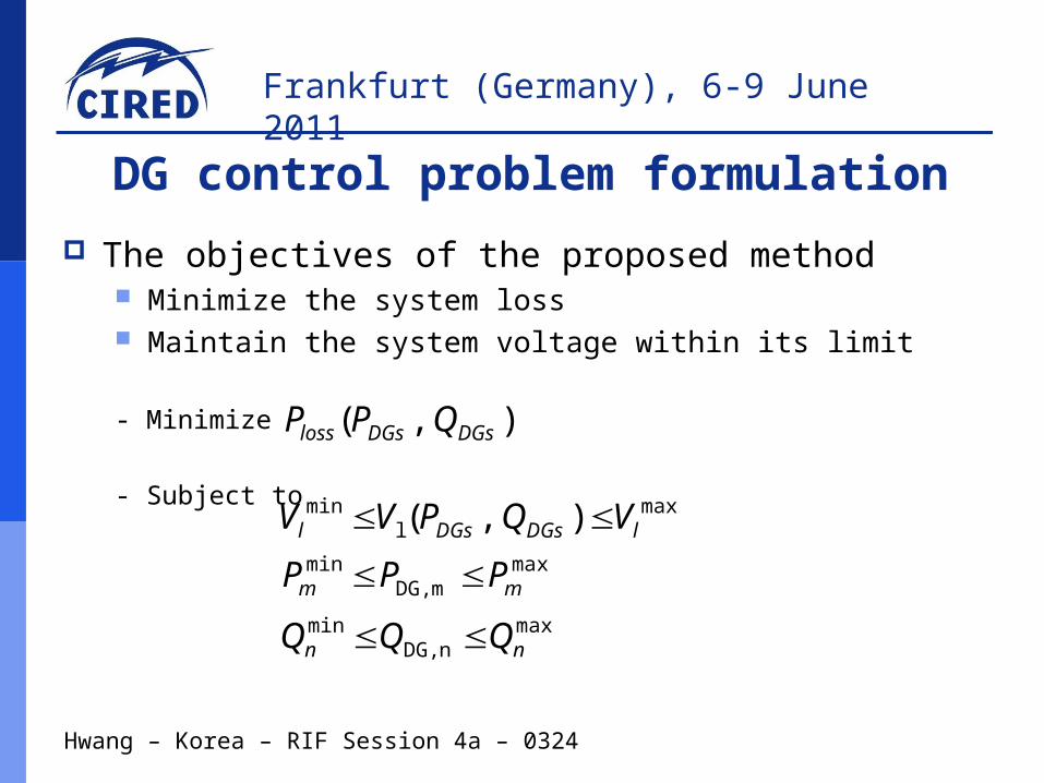
The objectives of the proposed method Minimize the system loss Maintain the system voltage within its limit
- Minimize
- Subject to
Hwang – Korea – RIF Session 4a – 0324
DG control problem formulation
) ,(
maxnDG,
min
maxmDG,
min
maxl
min
nn
mm
lDGsDGsl
QQQ
PPP
VQPVV
) ,( DGsDGsloss QPP

Frankfurt (Germany), 6-9 June 2011
Relationship among loss, voltage, and output of DGs is highly non-linear Formulated DG control problem is a non-linear optimization
problem
Sequential Linear Programming(SLP) method is adopted Optimal solution is calculated by solving series of linear
programming (LP) problem linearized at the operation point Operation point is determined at the previous iteration
Hwang – Korea – RIF Session 4a – 0324
Sequential Linear Programming

Frankfurt (Germany), 6-9 June 2011
Sub-functions of SLP LP formulation Step size adjustment Convergence test
Decision variable for LP
Hwang – Korea – RIF Session 4a – 0324
SLP application to DG control
DGs
DGs
Q
PX
Frankfurt (Germany), 6-9 June 2011
Linearized Optimization problem
-Minimize
-Subject to
Hwang – Korea – RIF Session 4a – 0324
LP formulation
X
X
QX
P
Q
V
P
VQP
V
PP
bus
bus
busbus
busbuslossloss
||||||
1max
1max
1min
1min
min1
1max
||||
||||
nDGsDGs
nDGsDGs
nDGsDGs
nDGsDGs
lnl
nll
bus
bus
busbus
busbus
PPX
PP
VV
VVX
X
QX
P
Q
V
P
VQ
V
P
V
Loss sensitivity matrixVoltage sensitivity matrixInjection power sensitivity matrix

Frankfurt (Germany), 6-9 June 2011
Differences between distribution system and transmission system Existence of mutual impedance in line parameter Unbalanced connection of DGs
Bus admittance matrix with mutual line impedance Used for calculation of loss and voltage sensitivity matrices
A : bus incidence matrix, [y] : primitive admittance matrix.
Hwang – Korea – RIF Session 4a – 0324
LP formulation
AyAY Tbus ][

Frankfurt (Germany), 6-9 June 2011
Injection power sensitivity matrix calculation method
Hwang – Korea – RIF Session 4a – 0324
LP formulation
A=zeros(N, M)
for i=1:1:M
switch connection topology of P(Q) controllable DG i
case : single phase
A(bus #, i)=1
case : two phase
A(bus # 1, i)=1/2; A(bus # 2, i)=1/2
case : three phase
A(bus # 1, i)=1/3; A(bus # 2, i)=1/3; A(bus # 3, i)=1/3
Frankfurt (Germany), 6-9 June 2011
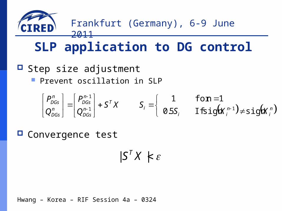
Step size adjustment Prevent oscillation in SLP
Convergence test
Hwang – Korea – RIF Session 4a – 0324
SLP application to DG control
XSQ
P
Q
P T
nDGs
nDGs
nDGs
nDGs
1
1
ni
nii
i XXSS
signsign If 5.0
1nfor 11
|| XST

Frankfurt (Germany), 6-9 June 2011
Flow chart of the proposed method
Hwang – Korea – RIF Session 4a – 0324
Proposed method
Frankfurt (Germany), 6-9 June 2011
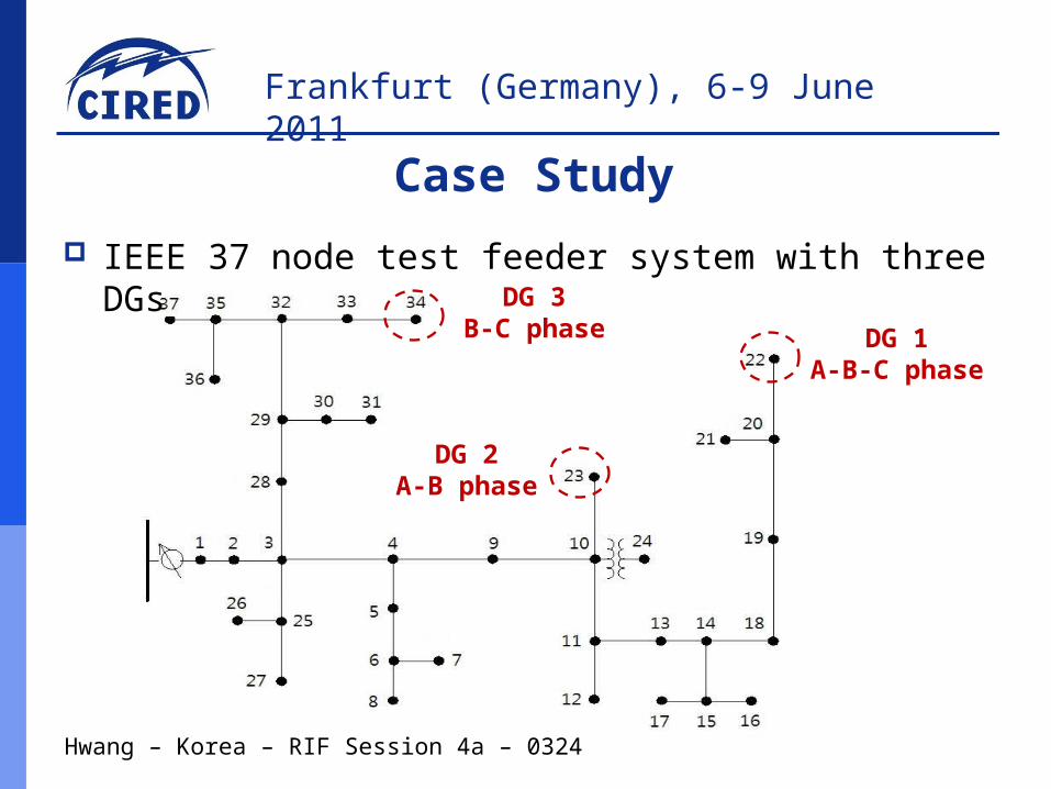
DG 1A-B-C phase
DG 2A-B phase
DG 3B-C phase
IEEE 37 node test feeder system with three DGs
Hwang – Korea – RIF Session 4a – 0324
Case Study

Frankfurt (Germany), 6-9 June 2011
Under voltage violation is occurred in case 2 and case 3
Hwang – Korea – RIF Session 4a – 0324
Initial voltage vs. voltage limit
0 5 10 15 20 25 30 35 400.96
0.97
0.98
0.99
1.00
1.01
1.02
1.03
1.04
Case 3
Case 3
Case 2
Case 2
Case 2
Case 1
Case 1
Node V
oltage (
p.u
.)
Node Number
Phase A Phase B Phase C
Under Voltage
Frankfurt (Germany), 6-9 June 2011
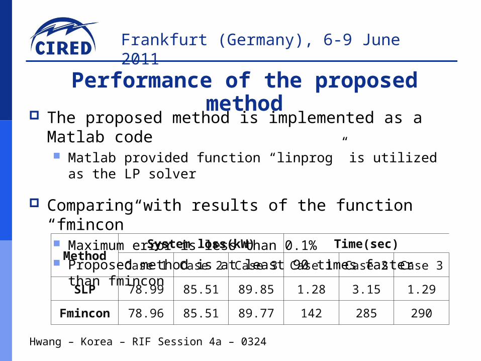
The proposed method is implemented as a Matlab code Matlab provided function “linprog” is utilized as the LP solver
Comparing with results of the function “fmincon” Maximum error is less than 0.1% Proposed method is at least 90 times faster than fmincon
Hwang – Korea – RIF Session 4a – 0324
Performance of the proposed method
MethodSystem loss(kW) Time(sec)
Case 1 Case 2 Case 3 Case 1 Case 2 Case 3
SLP 78.99 85.51 89.85 1.28 3.15 1.29
Fmincon 78.96 85.51 89.77 142 285 290

Frankfurt (Germany), 6-9 June 2011
The system loss is reduced about 19 %(97kW 78 kW)
Operation cost can be reduced by minimizing the loss
Hwang – Korea – RIF Session 4a – 0324
Case 1 ( Vmin = 0.97 p.u., Vmax = 1.03 p.u. )
0 5 10 15 20 25 30 35 40
0.98
0.99
1.00
1.01
1.02
Node V
olta
ge (p.u
.)
Node Number
Phase A Phase B Phase C

Frankfurt (Germany), 6-9 June 2011
Without proposed method, tap position of OLTC must be changed to eliminate the voltage violation Increasing operation cost
With proposed method, Under violation is eliminated without tap changing
System operation cost can be reduced by preventing the tap changing of OLTC
System stability can be improved by maintaining system voltage within its limit
Hwang – Korea – RIF Session 4a – 0324
Case 2 ( Vmin=0.98 p.u., Vmax=1.02 p.u.)

Frankfurt (Germany), 6-9 June 2011
System voltage
Hwang – Korea – RIF Session 4a – 0324
Case 2 ( Vmin=0.98 p.u., Vmax=1.02 p.u.)
0 5 10 15 20 25 30 35 40
0.98
0.99
1.00
1.01
1.02
Nod
e V
olta
ge (p.
u.)
Node Number
Phase A Phase B Phase C

Frankfurt (Germany), 6-9 June 2011
Tap changing to eliminate the under voltage violation
New over voltage violation is occurred
Hwang – Korea – RIF Session 4a – 0324
Case 3 ( Vmin=0.985 p.u., Vmax=1.015 p.u.)
0 5 10 15 20 25 30 35 400.98
0.99
1.00
1.01
1.02
Node V
olta
ge (p.u
.)
Node Number
Phase A Phase B Phase C
Over voltage

Frankfurt (Germany), 6-9 June 2011
System voltage can be maintained within its limit
Power quality can be enhanced by controlling the voltage more tightly
Hwang – Korea – RIF Session 4a – 0324
Case 3 ( Vmin=0.985 p.u., Vmax=1.015 p.u.)
0 5 10 15 20 25 30 35 400.98
0.99
1.00
1.01
1.02
Node V
olta
ge (p.u
.)
Node Number
Phase A Phase B Phase C

Frankfurt (Germany), 6-9 June 2011
Hwang – Korea – RIF Session 4a – 0324
Conclusions
Frankfurt (Germany), 6-9 June 2011
Hwang – Korea – RIF Session 4a – 0324
Thank You !([email protected])


