
Kobelt ManufacturingHydraulic Steering & Accessories Catalogue
17" x 11" Trim – 17-1/4" x 11-1/4" Bleed — Folds to 8-1/2" x 11"4/C + Gloss Varnish
Page 1 – Outside covers
YEL MAG CYAN BLK
P U S H - P U L L C O N T RO L SH Y D R A U L I C S T E E R I N G & A C C E S S O R I E S
E L E C T RO N I C C O N T RO L SP N E U M AT I C C O N T RO L S
D I S C B R A K E S
8238 129th Street, Surrey
British Columbia, Canada V3W 0A6
Sales: 604.590.7313 Fax: 604.590.8313
[email protected] www.kobelt.com
5M 09/00 PRINTED IN CANADA
KOBELT ASIA PTE. LTD.
Block 13, Unit 03-03 Braddell Tech
Lorong 8, Toa Payoh, Singapore 319261
Telephone: 65 35 63 800 Fax: 65 35 63 875
All Kobelt equipment comes with a 5-year warranty that is the best in the industry. Strict quality control manufacturing and sturdy corrosion-resistant materials ensure trouble-free serviceabove and beyond this generous warranty period.

Kobelt ManufacturingHydraulic Steering & Accessories Catalogue
17" x 11" Trim – 17-1/4" x 11-1/4" Bleed — Folds to 8-1/2" x 11"4/C + Gloss VarnishPage 2 – Inside covers
YEL MAG CYAN BLK
3
CONTROL YOUR SHIP WITH COMPLETE SYSTEMS AND COMPONENTS FROM KOBELT MANUFACTURING
1
2
5
4
6
7
8
9
10
1 Steering components up to 320 tonmeter for hydraulicsteering of single and multi-rudder vessels
2 In the aftdeck control station, complete control over allpropulsion and deck machinery.
3 Hydraulic cylinders and control devices for lowering andraising masts, davits for lifeboats, loading ramps etc.
4 Weatherproof controls for outside stations to controlpropulsion and deck machinery.
5 Control components for propulsion and deck machinery, pluselectronic alarm systems and electronic telegraphs.
6 Control for all deck machinery such as anchor and towing winches.
7 Controls for bow thrusters.
8 Control components for any propulsion package, fixed pitch CP propellers, load share and load control.
9 Propeller shaft disk brakes, from small engines up to 50,000 HP.
Control components to control stern thrusters.10
ver since our humble beginnings in 1962, Kobelt Manufacturing
Limited has been committed to manufacturing the finest marine
controls in the world. We stress the importance of quality, precision,
competitive pricing and prompt delivery. Our team of dedicated
production staff is uncompromising in ensuring that we meet the
needs of all our valued customers. Our growing reputation in world
markets is proof of our commitment to highest possible standards.
From our very first line of pneumatic controls we’ve believed in the
simple things—rugged construction, quality materials and prompt
delivery to our customers. Today, the technology has changed, but
our commitment remains the same. From our innovations in electronic
controls to our craftsmanship with bronze and stainless steel, our
products span the oceans of the world to further our reputation as
an international leader in maritime technology.
Kobelt Manufacturing, Surrey, British Columbia, Canada

P U S H - P U L L C O N T R O L S 1
WHY ARE KOBELT CONTROLS THE BEST?All components are made from die cast brass with stainless
steel hardware.
1. Solid brass frame for watertight installation.
2. Stainless steel shaft supported in two bearings.
3. Large pins and bearings for long life.
4. Roller type detent.
5. Adjustable nylon throttle friction.
6. Neutral safety switch.
7. In-line push or pull on cable end.
8. Removable solid brass dome.
9. Reverse motion hook-up for clutch and throttle.
10. Several connection points for cable to suit engine and gear.
11. Over-riding throttle (pull out).
Mounting screws under the dome.
Easy installation and maintenance.
Throttle movement proportional to handle travel.
All parts interchangeable.
Five year warranty with sales and service around the world.
Kobelt push-pull controls are manufactured under one or
more of the following Patent Numbers, further patents pending.
Canadian U.S. Patent Numbers Patent Numbers1153673 42803711158136 43266121206842 44534281185878 45124511176139 44704921166097 44781091202292 4592526
4730507
For more information contact:
Dealer
Brochures on many of our other products are available.
No other control can offer all the above and match the Kobelt Price.
K O B E L T C O N T R O L S
11
4 1
3
5
9
2
8
10
7
6
Push-Pull Cat REVISED 9/4/03 8:21 AM Page 1
2 P U S H - P U L L C O N T R O L S Q U I C K S E L E C T I O N G U I D E 3P U S H - P U L L C O N T R O L S Q U I C K S E L E C T I O N G U I D E
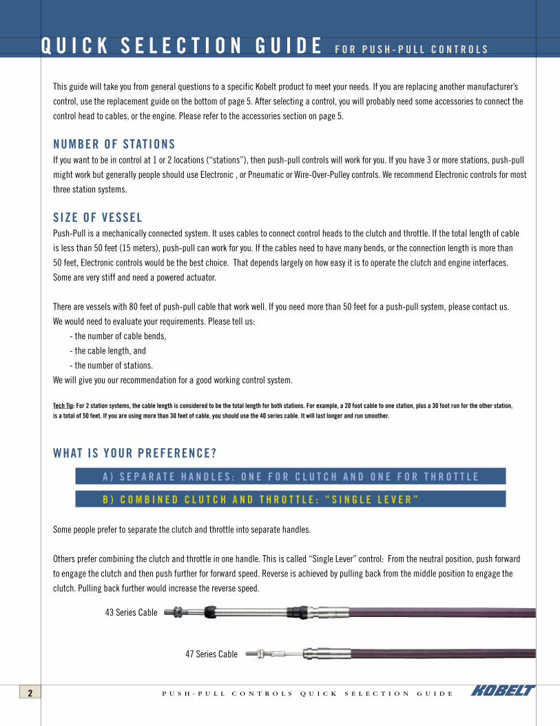
This guide will take you from general questions to a specific Kobelt product to meet your needs. If you are replacing another manufacturer’s
control, use the replacement guide on the bottom of page 5. After selecting a control, you will probably need some accessories to connect the
control head to cables, or the engine. Please refer to the accessories section on page 5.
NUMBER OF STATIONS If you want to be in control at 1 or 2 locations (“stations”), then push-pull controls will work for you. If you have 3 or more stations, push-pull
might work but generally people should use Electronic , or Pneumatic or Wire-Over-Pulley controls. We recommend Electronic controls for most
three station systems.
SIZE OF VESSEL Push-Pull is a mechanically connected system. It uses cables to connect control heads to the clutch and throttle. If the total length of cable
is less than 50 feet (15 meters), push-pull can work for you. If the cables need to have many bends, or the connection length is more than
50 feet, Electronic controls would be the best choice. That depends largely on how easy it is to operate the clutch and engine interfaces.
Some are very stiff and need a powered actuator.
There are vessels with 80 feet of push-pull cable that work well. If you need more than 50 feet for a push-pull system, please contact us.
We would need to evaluate your requirements. Please tell us:
- the number of cable bends,
- the cable length, and
- the number of stations.
We will give you our recommendation for a good working control system.
Tech Tip: For 2 station systems, the cable length is considered to be the total length for both stations. For example, a 20 foot cable to one station, plus a 30 foot run for the other station, is a total of 50 feet. If you are using more than 30 feet of cable, you should use the 40 series cable. It will last longer and run smoother.
WHAT IS YOUR PREFERENCE?
A ) S E P A R A T E H A N D L E S : O N E F O R C L U T C H A N D O N E F O R T H R O T T L E
B ) C O M B I N E D C L U T C H A N D T H R O T T L E : “ S I N G L E L E V E R ”
Some people prefer to separate the clutch and throttle into separate handles.
Others prefer combining the clutch and throttle in one handle. This is called “Single Lever” control: From the neutral position, push forward
to engage the clutch and then push further for forward speed. Reverse is achieved by pulling back from the middle position to engage the
clutch. Pulling back further would increase the reverse speed.
Q U I C K S E L E C T I O N G U I D E F O R P U S H - P U L L C O N T R O L S
43 Series Cable
47 Series Cable
2 P U S H - P U L L C O N T R O L S Q U I C K S E L E C T I O N G U I D E 3P U S H - P U L L C O N T R O L S Q U I C K S E L E C T I O N G U I D E
A ) S E P A R A T E H A N D L E S : O N E F O R C L U T C H A N D O N E F O R T H R O T T L E
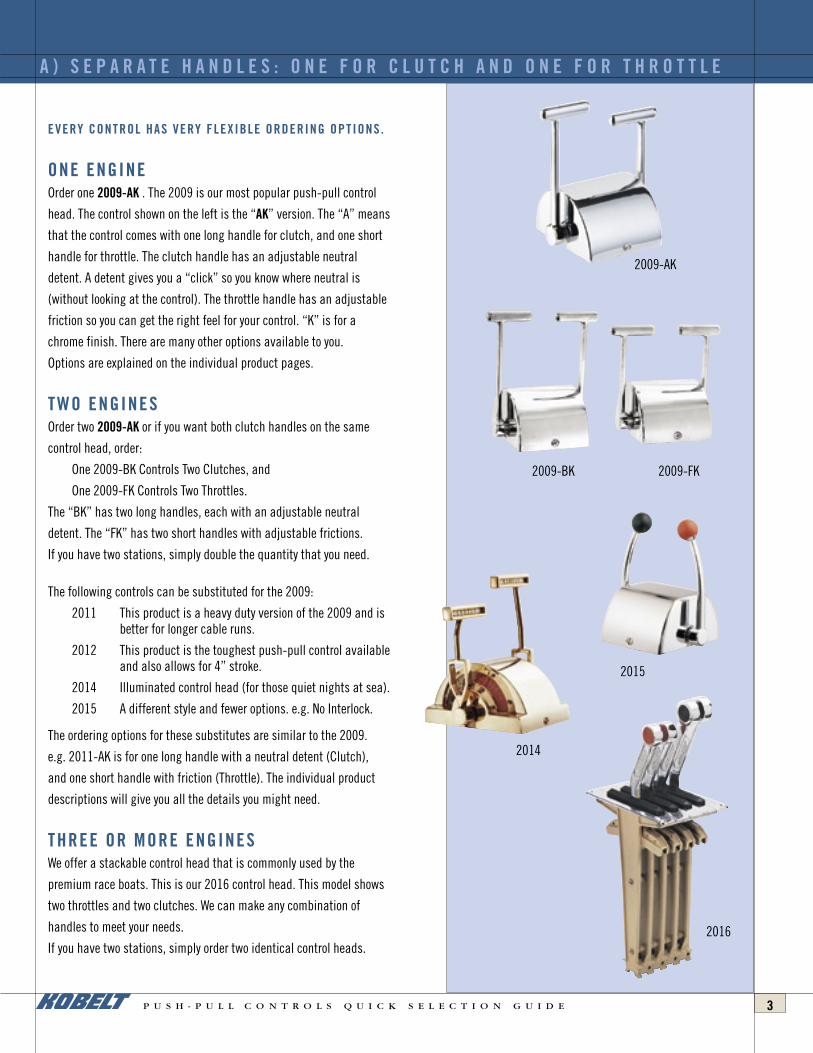
EVERY CONTROL HAS VERY FLEXIBLE ORDERING OPTIONS.
ONE ENGINEOrder one 2009-AK . The 2009 is our most popular push-pull control
head. The control shown on the left is the “AK” version. The “A” means
that the control comes with one long handle for clutch, and one short
handle for throttle. The clutch handle has an adjustable neutral
detent. A detent gives you a “click” so you know where neutral is
(without looking at the control). The throttle handle has an adjustable
friction so you can get the right feel for your control. “K” is for a
chrome finish. There are many other options available to you.
Options are explained on the individual product pages.
TWO ENGINES Order two 2009-AK or if you want both clutch handles on the same
control head, order:
One 2009-BK Controls Two Clutches, and
One 2009-FK Controls Two Throttles.
The “BK” has two long handles, each with an adjustable neutral
detent. The “FK” has two short handles with adjustable frictions.
If you have two stations, simply double the quantity that you need.
The following controls can be substituted for the 2009:
2011 This product is a heavy duty version of the 2009 and is better for longer cable runs.
2012 This product is the toughest push-pull control available and also allows for 4” stroke.
2014 Illuminated control head (for those quiet nights at sea).
2015 A different style and fewer options. e.g. No Interlock.
The ordering options for these substitutes are similar to the 2009.
e.g. 2011-AK is for one long handle with a neutral detent (Clutch),
and one short handle with friction (Throttle). The individual product
descriptions will give you all the details you might need.
THREE OR MORE ENGINES We offer a stackable control head that is commonly used by the
premium race boats. This is our 2016 control head. This model shows
two throttles and two clutches. We can make any combination of
handles to meet your needs.
If you have two stations, simply order two identical control heads.
2009-BK
2009-AK
2009-FK
2014
2016
2015

4 P U S H - P U L L C O N T R O L S Q U I C K S E L E C T I O N G U I D E 5P U S H - P U L L C O N T R O L S Q U I C K S E L E C T I O N G U I D E
ONE ENGINE
One Station
Order one 2046-KUZ. The 2046 is our most popular single-lever
control. It has various appearance options. Some of the options are:
• Curved or straight handles.
• Chrome, Black, or polished bronze
Alternatively you can choose one of these other controls:
2050 Very Heavy Duty control head, and has a separate small lever for throttle (engine warm up).
2042 Side mount control (mounts on side of panel, not top).
2043 Side mount control for heavy duty situations like controlling a small water jet’s bucket.
Two Stations
This is the best two station system on the market. The unique design
is very easy to operate. Order:
One 2091-KYZ Primary control head, and
One 2093-KYZ Secondary control head.
“KYZ” means chrome, straight handles, and a metal label on the dome.
The 2091 can be substituted with either of these controls:
2095 Illuminated primary control.
2081 Has a separate small lever for trolling.
2085 Illuminated version of 2081.
2044-91 Side mount primary control.
The 2093 can be substituted with:
2097 Illuminated secondary control.
TWO ENGINES
One Station
The 2047-KUZ is a twin engine version of the 2046 control head.
“KUZ” means chrome, curved handles and a metal label on the dome.
Two single engine controls can be used, such as the 2046.
B ) C O M B I N E D C L U T C H A N D T H R O T T L E : “ S I N G L E L E V E R ”
2046-KUZ
2047-KUZ
2091 KYZ2093 KYZ

4 P U S H - P U L L C O N T R O L S Q U I C K S E L E C T I O N G U I D E 5P U S H - P U L L C O N T R O L S Q U I C K S E L E C T I O N G U I D E
REPLACEMENT CONTROLS If you have one of these controls, we have a drop-in replacement for you.
2046-AK replaces Morse™ MT
2015-AK replaces Morse™ Twin S
2047-AK replaces Morse™ MT-2
B ) C O M B I N E D C L U T C H A N D T H R O T T L E : “ S I N G L E L E V E R ”
You will need cables and connection kits. Connection kits attach
the cable to the control head. There are 2 sizes: 33 series cable,
and 43 series cable. We recommend 43 series for longer life and
easier operation. You probably need connection kits and rod ball
ends for connecting the cables to your engine and clutch.
2092-KYZ
Two Stations
This is very similar to the 2091 and 2093 system. The 2092 is simply a
twin engine primary control head. To have a twin engine, two station,
single lever control system, order:
One 2092-KYZ Primary control for twin engine, and
One 2094-KYZ Secondary control.
The 2092 can be substituted with:
2096 Illuminated primary control.
The 2094 can be substituted with:
2098 Illuminated secondary control.
THREE OR MORE ENGINES For three or more engines, single station, we offer the 2020 Control
head. Information for this new product will be added here in February.
N E E D A C C E S S O R I E S ?For the 2091, 2092, 2093, 2094 controls, you will need 47 series
cable to interconnect the primary and secondary controls. These
are special low-friction pull-pull cables. Kobelt carries a large
stock of these cables, and they can also be acquired from Felsted.
The kits for the 47 series cables are included with the control head.

STANDARD FEATURESOur control heads are available in a polished brass
finish, polished chrome and black epoxy. When ordering please
state finish required. The controls are equipped with adjustable
friction or detent. A choice of various handle lengths is
available; when ordering please specify. Neutral safety switches
are available for all models. Stroke limitation screws are also
provided on one and two handle control heads. All domes are
removable for easy installation and adjustment. Kobelt
Manufacturing produces a vast number of different control
components and it is, therefore, very easy for us to produce
custom-made control heads, all simply assembled from
standard components in various configurations.
When ordering control heads, specify model number and
letter code designation.
Ordering Information:
Letter code designationsA – One short handle with friction and one long handle with detent.
AA – One short handle with friction and one long handle with friction.B – Two long handles with detent.C – Two long handles with friction.D – Two long handles with one detent and one friction.E – Two short handles with detent.F – Two short handles with friction.G – Two short handles with one detent and one friction.
*H – With one neutral safety switch.*J – With two neutral safety switches.K – With chrome finish cover and handle.L – With polished brass finish cover and handle.M – With black epoxy finish cover and chrome handle.N – One long handle with detent.
NN – One long handle with friction and detent.O – One long handle with friction.P – One short handle with detent.
PP – One short handle with friction and detent.R – One short handle with friction.S – Right hand model.T – Left hand model.U – Curved handle.V – T-bar handle with coloured plastic grips.W – Removable sailboat handle.X – Neutral locking powerbook handle.Y – T-bar handle (standard).Z – With riveted metal labels.
When ordering Kobelt adapter kits for control heads, specify the control head number
followed by -0901 for 30 series adapter kit and -0902 for 40 series adapter kit.
For neutral safety switch please specify control head number followed by -0903.
*Neutral safety switch is normally installed with detented handle.
P U S H - P U L L C O N T R O L S6
K O B E L T C O N T R O L S
P U S H - P U L L C O N T R O L S 7
BASIC INFORMATION ON PUSH-PULL CONTROLS
The mechanical push-pull control is a very simple and easily
installed system for smaller boats. The equipment controlled by a
system of this type must be relatively easy to operate. Kobelt
provides a variety of hydraulic-actuated power assist units for use
on clutch and throttle applications requiring additional
mechanical force (Part No. 4602, 4605).
We generally do not recommend the installation of more than
two stations with push-pull cables. If the cable runs are relatively
short and straight, it is possible to make a three-station system
work. For a multi-station, single lever control system, a combination
of wire-over-pulley and push-pull with our model 2051 master
control works extremely well (for up to four stations).
The Kobelt single lever control heads 2042, 2043, 2044,
2046, 2047, 2048, 2050 and 2054 are designed to work as a
one-station control only.
The 2080 series and the 2090 series are designed for 2
stations. These controls provide single lever control for clutch and
throttle from two stations and are available in single and twin
engine configuration. This system (Patent No. CDN. 1206642,
1158136; US 4512451, 4280371, Further Patent Pending) has
proven to be a tremendous success since there is no other control
system that even comes close for performance and durability.
Kobelt also produces complete systems for wire-over-pulley,
electronic and pneumatic controls, as well as propeller shaft
brakes and electrical control components. Since Kobelt has a total
commitment to better design, most of our products are patented.
Kobelt products, which already have an enviable reputation for
durability and performance, are constantly being improved.
Our success is based on the simple fact that we are the only
manufacturer in the world providing a non-corrosive product for
the marine environment. Our well-engineered products and
selection of only the best materials has put Kobelt into an
exclusive class in terms of quality and performance, enabling us
to offer our customers a five-year warranty.
Kobelt controls are sold through distributors worldwide. If you
are not already a Kobelt user, please do yourself a favour and
contact your nearest distributor.
GENERAL INFORMATIONKobelt Manufacturing does not produce a push-pull cable.
There are many push-pull cable manufacturers in the world
working with the same dimensional specifications, therefore, the
cables are all interchangeable. There is, however, a tremendous
variation in the structural quality and design. We recommend the
use of low friction cables with flexible cores, such as those
manufactured by Felsted®.
TECHNICAL SPECIFICATIONSThe Kobelt control heads are designed to be used with either
30 or 40 series cable so please specify when ordering. Our heads
and adapter kits are also designed to accept the clamp type cable
ends. The minimum bending radius recommended by us is 8"
(200mm), the maximum loading in push and pull mode on the 30
series cable should not exceed 50 lbs. (22kg) and the maximum
load on a 40 series cable should not be greater than 100 lbs. (45kg).
INSTALLATION INSTRUCTIONSA push-pull control system is dependent largely upon the
quality of the cable and the layout of the installation. An excessive
number of bends, especially small radius bends, will make a
control system of this nature stiff and difficult to handle. It must
be installed to eliminate as many bends as possible and also
provide generous radii, especially on multi-station installations.
On long and multi-station cable runs we can provide ball bearing
cables to reduce the friction and lost motion from conventional
cables. These cables are very expensive and Kobelt electronics or
air controls, in many cases, will do the job just as efficiently for
less. Kobelt only recommends the use of ball bearing cables when
there is absolutely no way of installing compressed air, electronics
or a wire-over-pulley system.
POWER ASSIST UNITSKobelt also provides a variety of hydraulic power assist
cylinders to aid the push-pull cable in controlling clutches and
throttles. For further details regarding servo cylinders and product
numbers 4602, 4605 and 4607, please refer to page 24 or consult
our factory or your nearest distributor.
P U S H - P U L L C O N T R O L S
Push-Pull Cat REVISED 9/4/03 8:21 AM Page 3

P U S H - P U L L C O N T R O L S8
Our Model 2002 is designed for small workboats and pleasure crafts for single or two station control
of engine speed and gear box direction. Its rugged design, simplicity of construction and quality of material
(brass, and stainless steel hardware) will give years of trouble-free service with a minimum investment.
The throttle must be at idle before the gear control lever can be moved to any position. This feature will
protect the gear box since the engine must be at idle for clutch shifting.
Letter code designations:
S, T
Designed and built with careful attention to quality of materials and workmanship, the rugged design
incorporates practicality and contemporary styling. The all-brass and stainless steel construction of these
control heads will give years of trouble free operation.
Model 2003 and 2004 provide 3" (76mm) of cable stroke and Model 2006 provides 4" (102mm) of
cable stroke. All one-handle and two-handle Kobelt control heads are equipped with frictions or detents as
standard. Neutral safety switches are an optional extra; see ordering table.
Letter code designations:
H, K, L, M, N, O, P, R, V, Y, Z
2 0 0 2 TWIN HANDLE BRASS CONTROL HEAD 3" STROKE
2 0 0 3 / 2 0 0 4 / 2 0 0 6 O N E H A N D L E H E AV Y D U T Y C O N T R O L H E A D S
A B C D E F G H I J K
MODEL 11-1/16" 5-17/32" 5-1/16" 5-13/64" 7" 6" 7-1/4" 4-1/4" 1-15/16" 1-5/16" 4-9/32"2003 (281) (1405) (1286) (132.2) (177.8) (1524) (1842) (108) (492) (333) (1087)
MODEL 13-1/2" 6-3/4" 6-1/15" 4-1/4" 8-7/8" 7-1/2" 8-3/4" 5-5/16" 2-1/2" 2-1/2" 4-3/4"2004 (3429) (1715) (154) (108) (2254) (1905) (222.3) (1349) (635) (635) (1207)
MODEL 13-1/2" 6-3/4" 7-1/8" 4-1/4" 8-7/8" 7-1/2" 8-3/4" 6-3/8" 2-1/2" 2-1/2" 5-1/2"2006 (342.9) (171.5) (181) (108) (255.4) (190.5) (222.3) (161.9) (63.5) (63.5) (139.7)
Push-Pull Cat REVISED 9/4/03 8:21 AM Page 4
P U S H - P U L L C O N T R O L S 9
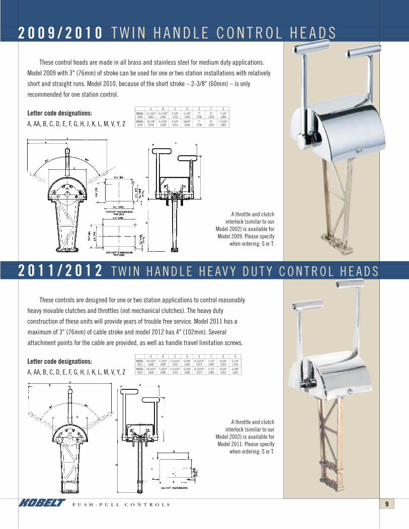
These control heads are made in all brass and stainless steel for medium duty applications.
Model 2009 with 3" (76mm) of stroke can be used for one or two station installations with relatively
short and straight runs. Model 2010, because of the short stroke – 2-3/8" (60mm) – is only
recommended for one station control.
Letter code designations:
A, AA, B, C, D, E, F, G, H, J, K, L, M, V, Y, Z
A throttle and clutchinterlock (similar to our
Model 2002) is available forModel 2009. Please specify
when ordering: S or T.
A throttle and clutchinterlock (similar to our
Model 2002) is available forModel 2011. Please specify
when ordering: S or T.
These controls are designed for one or two station applications to control reasonably
heavy movable clutches and throttles (not mechanical clutches). The heavy duty
construction of these units will provide years of trouble free service. Model 2011 has a
maximum of 3" (76mm) of cable stroke and model 2012 has 4" (102mm). Several
attachment points for the cable are provided, as well as handle travel limitation screws.
Letter code designations:
A, AA, B, C, D, E, F, G, H, J, K, L, M, V, Y, Z
2 0 0 9 / 2 0 1 0 T W I N H A N D L E C O N T R O L H E A D S
2 0 1 1 / 2 0 1 2 T W I N H A N D L E H E AV Y D U T Y C O N T R O L H E A D S
A B C D E F G
MODEL 11-1/16" 5-17/32" 5-1/4" 6-1/8" 7" 6" 7-1/4"2009 (281) (140) (133) (156) (178) (152) (184)
MODEL 10-7/8" 5-7/16" 4-3/4" 503/4" 7" 6" 7-5/16"2010 (276) (138) (121) (146) (178) (152) (186)
A B C D E F G H
MODEL 14-3/16" 7-3/32" 5-15/16" 6-5/8" 8-15/16" 7-1/2" 8-3/4" 5-1/4"2011 (360) (180) (151) (168) (227) (190) (222) (133)
MODEL 14-3/16" 7-3/32" 5-15/16" 6-5/8" 8-15/16" 7-1/2" 8-3/4" 6-3/8"2012 (360) (180) (151) (168) (227) (190) (222) (162)

P U S H - P U L L C O N T R O L S10
This control incorporates all the features of the Kobelt standard Push Pull Control:
3" strokes, all bronze and stainless steel, and extremely heavy duty construction. The
cable support bracket has been shortened to improve cable attachment access to the
Control head.
Letter code designations:
A, AA, B, C, D, E, F, G, K, L, M, U, V
2 0 1 5 T W O H A N D L E P U S H - P U L L C O N T R O L H E A D
Push-Pull Cat REVISED 9/4/03 8:22 AM Page 6
P U S H - P U L L C O N T R O L S 11
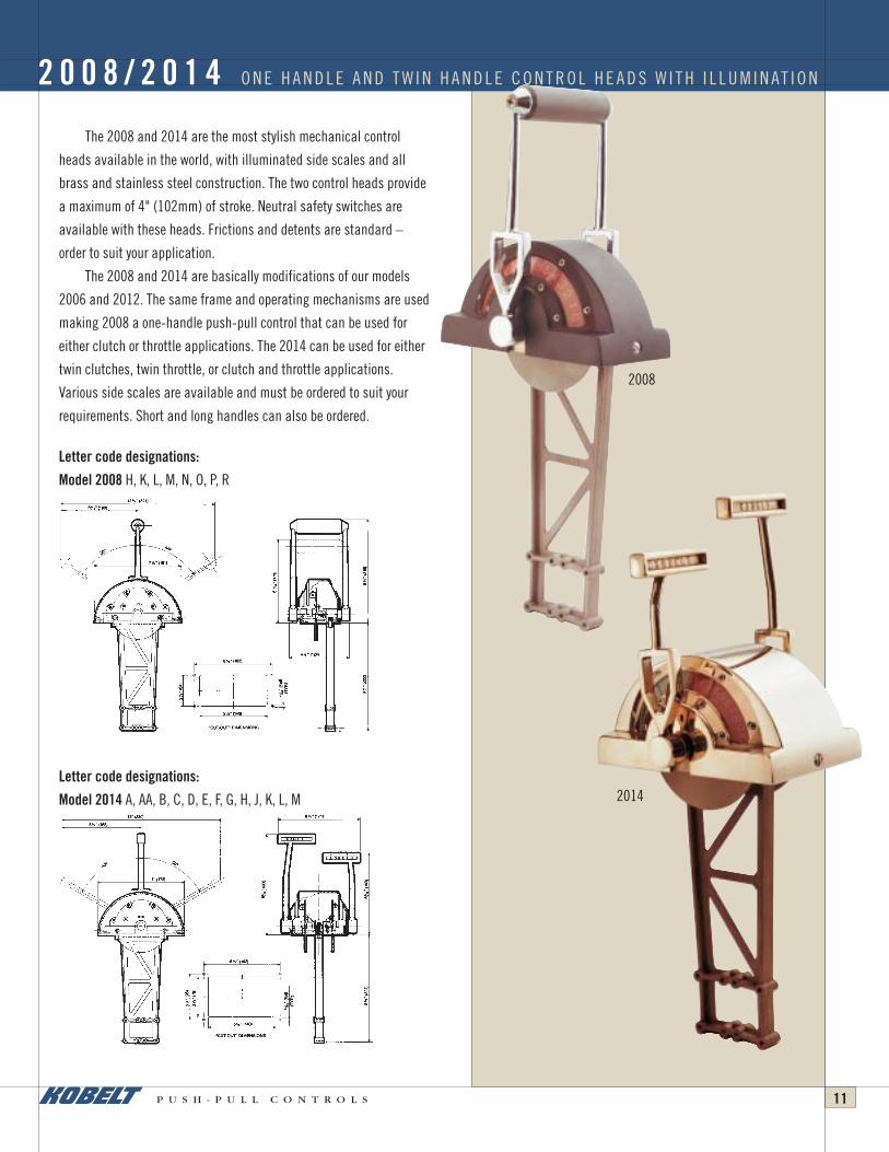
The 2008 and 2014 are the most stylish mechanical control
heads available in the world, with illuminated side scales and all
brass and stainless steel construction. The two control heads provide
a maximum of 4" (102mm) of stroke. Neutral safety switches are
available with these heads. Frictions and detents are standard –
order to suit your application.
The 2008 and 2014 are basically modifications of our models
2006 and 2012. The same frame and operating mechanisms are used
making 2008 a one-handle push-pull control that can be used for
either clutch or throttle applications. The 2014 can be used for either
twin clutches, twin throttle, or clutch and throttle applications.
Various side scales are available and must be ordered to suit your
requirements. Short and long handles can also be ordered.
Letter code designations:
Model 2008 H, K, L, M, N, O, P, R
2008
2014Letter code designations:
Model 2014 A, AA, B, C, D, E, F, G, H, J, K, L, M
2 0 0 8 / 2 0 1 4 O N E H A N D L E A N D T W I N H A N D L E C O N T R O L H E A D S W I T H I L L U M I N AT I O N
Push-Pull Cat REVISED 9/4/03 8:22 AM Page 7

P U S H - P U L L C O N T R O L S12
Hi-Performance Race Boat Control
This control is totally constructed in bronze and stainless steel. The levers can be
combined to suit customer requirements and an almost unlimited variety of control
functions can be accomplished.
The Model 2016 does not provide single lever control. Only ONE function can be
accomplished per lever.
Letter code designations:
A, A1, B, C, D, E, F, G, H, J,
K, L, M, MM, N, O, P, R
The 2030 side-mounted control, provides 3-1/4" (82mm) of cable stroke and can be used for control of
either clutch or throttle. Only one length of handle is available with this unit. The rugged design and large
bearing will provide years of trouble-free operation. The output cable attaching flange can be rotated at
90° increments.
Letter code designations:
K, L, M, N, O
2 0 1 6 S TA C K A B L E F L U S H M O U N T C O N T R O L S
2 0 3 0 S I D E - M O U N T O N E H A N D L E C O N T R O L
Push-Pull Cat REVISED 9/4/03 8:22 AM Page 8

P U S H - P U L L C O N T R O L S 13
These sidemount controls are intended to control water jets, power take-offs, small
mechanical clutches, and various other heavy duty applications where 60 series cable
is employed. The long handle on both units provides from 3" to 6" of stroke. The short
handle on Model 2031 will give from 1" to 3" of stroke. It is possible to use either model
on a two-station (in series) application whereby two levers are provided on the backside
of the control for the connection of two cables, one to the remote station and one to the
item to be controlled. The all bronze and stainless steel construction will give years of
trouble-free service.
Letter code designations:
Model 2031 K, L, M
Letter code designations:
Model 2032 J, K, L, M
2031
2032
2 0 3 1 T W O L E V E R 2 0 3 2 O N E L E V E R H E AV Y D U T Y S I D E - M O U N T C O N T R O L
Push-Pull Cat REVISED 9/4/03 8:22 AM Page 9
P U S H - P U L L C O N T R O L S14
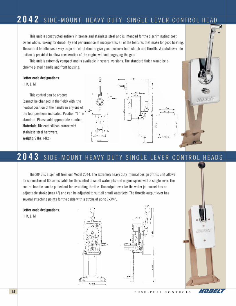
This unit is constructed entirely in bronze and stainless steel and is intended for the discriminating boat
owner who is looking for durability and performance. It incorporates all of the features that make for good boating.
The control handle has a very large arc of rotation to give good feel over both clutch and throttle. A clutch override
button is provided to allow acceleration of the engine without engaging the gear.
This unit is extremely compact and is available in several versions. The standard finish would be a
chrome plated handle and front housing.
Letter code designations:
H, K, L, M
This control can be ordered
(cannot be changed in the field) with the
neutral position of the handle in any one of
the four positions indicated. Position “1” is
standard. Please add appropriate number.
Materials: Die cast silicon bronze with
stainless steel hardware.
Weight: 9 lbs. (4kg)
The 2043 is a spin off from our Model 2044. The extremely heavy duty internal design of this unit allows
for connection of 60 series cable for the control of small water jets and engine speed with a single lever. The
control handle can be pulled out for overriding throttle. The output lever for the water jet bucket has an
adjustable stroke (max 4") and can be adjusted to suit all small water jets. The throttle output lever has
several attaching points for the cable with a stroke of up to 1-3/4".
Letter code designations:
H, K, L, M
2 0 4 2 S I D E - M O U N T, H E AV Y D U T Y, S I N G L E L E V E R C O N T R O L H E A D
2 0 4 3 S I D E - M O U N T H E AV Y D U T Y S I N G L E L E V E R C O N T R O L H E A D S
Push-Pull Cat REVISED 9/4/03 8:22 AM Page 10

P U S H - P U L L C O N T R O L S
Single Station Use Only
The Model 2044 is available in two different versions, (as shown) with neutral lock for powerboats
and with removable sailboat handle (not shown). Also not shown is model 2045 with remote wire over
pulley control which lends itself ideally, in this configuration, for small workboats with wire over pulley
control leading to upper stations. This control features a pull out handle for overriding throttle. The clutch
travel is a maximum of 3" (76mm) and the throttle travel is 1-3/4" (44mm). The cable attaching bracket
can be rotated at 90° increments. The control handle position can also be ordered at 90° increments.
Letter code designations:
H, K, L, M, W, X
This control head was recently developed by Kobelt Manufacturing, as a smaller version of the
2048, and it incorporates all of the same features. The throttle travel is 2-3/8" and the maximum clutch
travel is 3".
This unit is constructed entirely of bronze and stainless steel and offers a five year warranty.
It can be used in either push or pull mode for the clutch or throttle. A roller type detent is incorporated
into the 2047 as well as an independent throttle override.
Letter Code Designations
J, K, L, M, U, V, Y, Z
Important: Model 2047 is designed
to work as a single station unit only.
If two stations are to be interconnected,
transfer unit must be used.
Weight: 8.8 lbs. (4kg)
2 0 4 4 S I D E - M O U N T, H E AV Y D U T Y, S I N G L E L E V E R C O N T R O L H E A D S
2 0 4 7 S I N G L E L E V E R C O N T R O L H E A D
15
Push-Pull Cat REVISED 9/4/03 8:22 AM Page 11

P U S H - P U L L C O N T R O L S16
Single Station Use Only
The 2046 and 2048 single lever control heads, went through years of engineering and feasibility
studies before we presented these products to the market. These control heads are a major evolution in
single lever control because of their construction, design, size, price and options which puts them in a
class by themselves; just like all other Kobelt products. They provide a pull-out handle for over-riding
throttle, roller detents and enumerable options. The clutch travel is maximum 3" (76mm) and throttle travel
is maximum 1-5/8" (41mm). The 2048 consists of two 2046’s jointed on a common frame and dome.
An optional throttle stroke extension kit is available for Models 2046 and 2048. It will extend throttle
stroke to 2-5/8" and contains all necessary parts to connect either a 33 or 43 series cable.
Part #2046-0905 for 33 series cable
Part #2046-0906 for 43 series cable
Letter code designations:
Model 2046 H, K, L, M, U, V, Y, Z
Letter code designations:
Model 2048 J, K, L, M, U, V, Y, Z
2046
2 0 4 6 / 2 0 4 8 M E D I U M D U T Y S I N G L E L E V E R C O N T R O L H E A D S
2048
Push-Pull Cat REVISED 9/4/03 8:22 AM Page 12

P U S H - P U L L C O N T R O L S 17
Single Station Use Only
The 2050 and 2054 are super heavy duty control heads using basically the same components
except for the dome and handles. All materials are non-corrosive and are designed for years of
trouble-free service. The maximum travel for the clutch is 3" (76mm) and the maximum throttle
travel is 2-1/2" (64mm) for the 2050. While the clutch travel for the 2054 is the same, the throttle
stroke is 2" (50mm). Various connection points provide the correct travel needed for your engine
and gear. The small over-riding throttle handle is only operative in the neutral gear position which
prevents gear engagement at high engine speed. The 2054 (the same as 2008 and 2014) is
equipped with light sockets for illumination. Dimmers can be provided to regulate the light effect
to suit the owner. Many boats equipped with our 2050 series control heads have push-pull cable
runs up to 75 ft. (23m) and work very satisfactorily with felsted cables.
Letter code designations:
Model 2050 H, K, L, M, NN, PP, S, T, V, Y, Z
Letter code designations:
Model 2054 H, K, L, M, NN, PP
2 0 5 0 / 2 0 5 4 H E AV Y D U T Y S I N G L E L E V E R C O N T R O L H E A D S
2050
2054
Push-Pull Cat REVISED 9/4/03 8:22 AM Page 13
P U S H - P U L L C O N T R O L S18
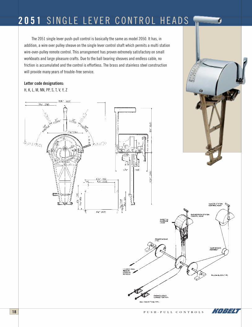
The 2051 single lever push-pull control is basically the same as model 2050. It has, in
addition, a wire over pulley sheave on the single lever control shaft which permits a multi station
wire-over-pulley remote control. This arrangement has proven extremely satisfactory on small
workboats and large pleasure crafts. Due to the ball bearing sheaves and endless cable, no
friction is accumulated and the control is effortless. The brass and stainless steel construction
will provide many years of trouble-free service.
Letter code designations:
H, K, L, M, NN, PP, S, T, V, Y, Z
2 0 5 1 S I N G L E L E V E R C O N T R O L H E A D S
Push-Pull Cat REVISED 9/4/03 8:22 AM Page 14

P U S H - P U L L C O N T R O L S 19
The 2061 and 2062 series control heads offer a single lever control
function with electric clutch and mechanical throttle; 2061 is for a single
engine application, 2062 is for a twin engine application. These control
heads are intended for a one station installation only. The micro switches will
give a forward- and reverse-direction signal and the push-pull cable will
provide control for the engine throttle. The unit is, like all our other products,
made of all brass die cast material with stainless steel hardware.
Maximum cable travel: 2" (51mm).
Maximum voltage: 110 volt.
Maximum current: 2 Ampere.
Letter code designations:
Model 2062: B, E, J, K, L, M, V, Y, Z
Letter code designations:
Model 2062: B, E, J, K, L, M, V, Y, Z
2061
2062
2 0 6 1 / 2 0 6 2 S I N G L E L E V E R , E L E C T R I C C L U T C H C O N T R O L H E A D S
Push-Pull Cat REVISED 9/4/03 8:22 AM Page 15

P U S H - P U L L C O N T R O L S20
Single Lever, Engine, Single Lever Control with overriding and interlocked Throttle Control.
Model 2081
This control operates basically on the same principle as the model 2090 with the exception
that the overriding throttle is on a separate lever. The throttle lever serves the prime function of
accelerating the engine while the main single lever control handle is in the neutral position. It is
not possible to operate both levers at the same time since they are mechanically interlocked.
Single Lever, Single Engine Control, with Separate Trolling Valve Lever.
Model 2085
This control is ideally suited for one or two station applications that require trolling valve
control. An interlock incorporated in this unit will only allow for trolling valve control at low
engine R.P.M.. The second station can be equipped with or without trolling valve control.
Remote Control with either overriding Throttle or Trolling Valve Control.
Model 2083
The purpose of this unit is to serve as a remote station with either Model 2081 or 2085. The
secondary lever is interconnected with the overriding throttle on Model 2081 or the trolling valve
control lever on Model 2085. The main single lever control is connected to the remote unit with
pull/pull cables (47 series.) For a second station throttle and clutch only use Model 2093.
Letter code designations:
H, I, K, L, M, S, T, U, V, Y, Z
2 0 8 0 S E R I E S
2081
Push-Pull Cat REVISED 9/4/03 8:22 AM Page 16

P U S H - P U L L C O N T R O L S 21
Patent No. CDN: 1206842, 1158136.
US: 4512451, 4280371
The 2090 Series is the only control of its type in the world and offers the
ultimate in simplicity, performance and durability. On a two-station system
both handles move together. For this reason only two control heads and four
cables are required for a complete single engine two-station system.
With all other controls of this type the control must be put into
neutral when going from one station to the next, the clutch re-engaged
and the engine accelerated at the next station. These systems, requiring
five components and seven cables, are constructed mainly from corrosive
materials. They do not work as well as Kobelt Controls and are more
expensive. For the short time that the 2090 Series Control System has been
on the market it has proven itself to be a tremendous success.
2 0 9 0 S E R I E S – T W O S TAT I O N S I N G L E L E V E R C O N T R O L S
To Clutch
To Throttle
Push-Pull Cat REVISED 9/4/03 8:22 AM Page 17

P U S H - P U L L C O N T R O L S22
Letter code designations:
Model 2092 (master) : J, K, L, M, U, Y, Z
Model 2094 (remote) : K, L, M, Z
The 2091 and 2092 master control heads feature a pull-out handle for
overriding throttle. All models are made entirely of die-cast silicon bronze and
stainless steel hardware and are backed up with our five year warranty. The
maximum clutch stroke is 2 3/4" (70mm) and the maximum throttle stroke is
2 1/4" (57mm). Various connection points provide the correct travel for your
engine and gear. The 2093 and 2094 remote controls are of the same rugged
design. While the 2091 and 2093 are the same size, model 2094 is narrower
than its master control, model 2092.
Letter code designations:
Model 2091 (master) : H, K, L, M, U, Y, Z
Model 2093 (remote) : K, L, M, U, Y, Z
2 0 9 1 / 2 0 9 2 / 2 0 9 3 / 2 0 9 4 T W O S TAT I O N S I N G L E L E V E R C O N T R O L S
2091
2092
Push-Pull Cat REVISED 9/4/03 8:22 AM Page 18

P U S H - P U L L C O N T R O L S 23
Letter code designations:
Model 2096 (master): J, K, L, M
Model 2098 (remote): K, L, M
The 2095 and 2096 are based on our models 2091 and 2092 with the addition of
illuminated side scales. Model 2096 has a pull-out overriding throttle which isn’t
available on the 2095. The clutch and throttle stroke is the same as the non-illuminated
models. Models 2097 and 2098 are illuminated remote control heads. It is possible to
combine illuminated and non-illuminated models. The 2095 and 2097 are the same size
while model 2098 is narrower than its master control 2096.
Letter code designations:
Model 2095 (master): H, K, L, M
Model 2097 (remote): K, L, M
2 0 9 5 / 2 0 9 6 / 2 0 9 7 / 2 0 9 8 T W O S TAT I O N S I N G L E L E V E R C O N T R O L S
2095
2096
Push-Pull Cat REVISED 9/4/03 8:22 AM Page 19

P U S H - P U L L C O N T R O L S24
Installation instructions for 2090 SeriesWhen installing the control heads, it is important that they are located on a clean and flat surface which is easily accessible. The cables leading
from the main control head to the reverse reduction gear and the propulsion engine throttle should be installed and made functional first. It isimportant that the following points are carefully observed.
As illustrated in the drawing in Position A (showing the clutch actuating pivot plate in the gear engaged position and the control handle in thefull speed position) the cable must pass slightly beyond the attaching point on the clutch actuating pivot plate in the pull mode. The cable must alsogo slightly beyond position B in the push mode with the control head in a full speed position.
In order to obtain equal excess travel in both positions on the cable, the adaptor kit cable-end must be adjusted accordingly. After the properposition is found, the cable-end is attached to the clutch actuating pivot plate. The locking nut must be secured. This will ensure that no mechanicalbinding takes place in the cable or the control head. It is also very important that the clutch control valve goes from neutral to both gear engagedpositions without bottoming. A slight amount of end play is essential.
The throttle cable attached to the throttle actuating cam must also operate within the available stroke of the cable and the adaptor kit cable-endmust be adjusted in such a manner to avoid bottoming of the control cable in either direction. In order to obtain full handle travel in the speed range itis important to select the appropriate connection point to the adaptor kit on the throttle cam.
After the master station is connected to the engine the cables can be connected from this station to the remote station. It is important that thecables are the right length. Too short a cable can result in tight bends which will increase friction. Too long a cable will also result in extra loops whichagain generate additional friction. Either of the above can make this control stiff and difficult to operate.
After the cable is attached with the clamps on the bottom of the supports of the control heads, the chain can be placed over the sprocket. Whenthe control head is in the neutral position (handle in mid-position), the loose ends of the chain should be equally long on either side of the sprocket.The cable core is equipped with two nuts on either end. One of the nuts must be removed and the cable-end passed through the adaptor link. The nutcan now be reinstalled.
It is also important to remember that the cable must be crossed between the control heads in order to get the handles to move in the samedirection (the forward cable from the master station is attached on the aft side of the remote station and the forward cable of the remote station isattached to the aft side of the master station). The cables have enough thread at the end to allow balancing of the handles at both stations. This isbest accomplished by placing the master station in the neutral position (handle straight up). The adjusting nuts at the end of the cable can now betightened or loosened as required to balance the handles. Over-tightening of the cable core will result in excessive friction and will make the controlsystem very stiff and difficult to operate. A deflection of 3/8"–1/2" in the cable to either side between the sprocket and cable conduit clamp isessential. It is important that the two nuts and the cable-end are secured tightly against the adapting link. Two wrenches (3/8") must be used toaccomplish this task. Under no circumstances must the chain be twisted when tightening these nuts.
Use only felsted pull-pull cables to interconnect head and felsted 40 series push-pull cables from control to gearbox/engine.It is extremely important that all screws and nuts be securely tightened before the boat is placed into operation.
2 0 9 0 I N S TA L L AT I O N I N S T R U C T I O N S
Push-Pull Cat REVISED 9/4/03 8:22 AM Page 20

P U S H - P U L L C O N T R O L S 25
These control heads are designed to provide a push-pull signal to either clutch or throttle and
also have a wire-over-pulley sheave on a common shaft. This allows for multi-station wire-over-
pulley remote control. The 2911 provides 3" (76mm) of stroke and has 4" (102mm) diameter sheave.
The 2912 provides up to 4" (102mm) of cable stroke and has 4 3/4" (121mm) diameter sheave.
Letter code designations:
H, K, L, M, N, O, P, R, V, Y, Z
The 2923 and 2924 control heads were developed to provide a combination of push-pull and
wire-over-pulley on one head. One handle controls a push-pull cable and one handle controls a
wire-over-pulley arrangement. This lends itself extremely well for engines driving the propeller
through a Twin Disc Omega Gear; the push-pull control regulates the engine speed and the wire-
over-pulley will give control over the Omega slip
clutch from “full ahead” to “full astern”. The 2923
has 3" (76mm) of stroke, and 2924, 4" (102mm)
of stroke, in the push-pull cable.
Letter code designations:
A, AA, B, C, D, E, F, G, H, J, K, L, M, V, Y, Z
2 9 1 1 / 2 9 1 2 C O M B I N AT I O N C O N T R O L H E A D S , S I N G L E H A N D L E , P U S H - P U L L A N D W I R E - O V E R - P U L L E Y
2 9 2 3 / 2 9 2 4 C O M B I N AT I O N C O N T R O L H E A D S , T W I N H A N D L E , P U S H - P U L L A N D W I R E - O V E R - P U L L E Y
MODEL A B C D E G
2911 7-1/2" (191) 8-3/4" (222) 8-3/4" (222) 5-9/16" (141) 5-15/16" (151) 60°
2912 7-1/2" (191) 8-3/4" (222) 8-3/4" (222) 5-9/16" (141) 7" (178) 55°
H J K L M N
3-3/4" (95) 5-1/4" (133) 3-1/2" (79) 4-5/8" (117) 14-1/4" (362) 7-1/2" (181)
3-3/4" (95) 603/8" (162) 3-1/2" (79) 5-1/2" (139) 14-1/4" (362) 7-1/2" (181)
MODEL A B C D E F
2923 7-1/2" (191) 8-3/4" (222) 8-15/16" (227) 6-3/8" (168) 5-15/16" (151) 80°
2924 7-1/2" (191) 8-3/4" (222) 8-15/16" (227) 6-3/8" (168) 7" (178) 80°
G H J K L M N
60° 3-3/4" (95) 5-1/4" (133) 3-1/2" (79) 4-5/8" (117) 16-1/2" (410) 8-1/16" (205)
55° 3-3/4" (95) 6-3/8" (162) 3-1/2" (79) 5-1/2" (139) 16-1/2" (410) 8-1/16" (205)
Push-Pull Cat REVISED 9/4/03 8:22 AM Page 21

P U S H - P U L L C O N T R O L S26
The Compound Unit was developed for two-station applications and for
use on compound engine arrangements. On two station applications, long
cables sometimes require the use of 40 series cable from the wheelhouse to
the engine room, but many in-board out-board engines are designed for
connection to a 30-series cable. The Compound Unit can be installed just
below the wheelhouse floor. Both stations are connected to it with a 30 or 40
series cable which runs to the clutch throttle. On compound engine
installations, the control cable runs into the Compound Unit and two cables
lead away to the separate engine throttles.
Cable connection kits are available for any combination of cables.
Kits include:
Ordering No. 33 Series Cable 43 Series Cable
2124-0033 3 –
2124-0043 – 3
2124-0143 2 1
2124-0243 1 2
The Universal Cable Transfer Unit is a very useful device in Push-Pull
Control systems where motion reversal is necessary or where the span of
movement must be altered. The ability to connect cables (up to 4) at various
connection points on the opposite side of the main lever provides all these
functions. It is possible to increase the stroke from 3" to 4" cable or reduce
the stroke from 3" to 2" cable. Construction is all bronze and stainless steel.
2 1 2 4 C O M P O U N D U N I T
2 1 2 3 U N I V E R S A L C A B L E T R A N S F E R U N I T
Push-Pull Cat REVISED 9/4/03 8:22 AM Page 22

P U S H - P U L L C O N T R O L S 27
Catch-A-Bolt
This universal adaptor kit was developed in order to avoid
stocking hundreds of different adaptor kits. Its title explains its
function. Virtually any bolt, or preferably two bolts on the gear or
engine, close to cable attaching point, can be used to install this
universal adaptor kit. With its linkage and swivelling ends,
cables can be run directly to the clamping bracket and allow
easy cable installation; this avoids costly designing and
fabrication. It can be used for parallel or series installations.
Clamp Kits for Model 2128
Cables Attached Ordering No.
one-30 series 2128-0031
two-30 series 2128-0032
one-40 series 2128-0041
two-40 series 2128-0042
Kobelt Manufacturing has developed an electric gearshift adaptor which
can be connected to all Push-Pull controls (Single and Two Lever except
Model 2010).
The purpose of this adaptor is to control electrically actuated clutch
controls.
The electric gear shift adaptor is easily installed in the control head. On
a two lever system, a second station can be connected with Push-Pull cables
to the master station. Solenoid valves are provided by the gear box
manufacturer to actuate the forward and reverse direction in the marine
gear. The electric gear shift adaptor is ordered with the control head number
followed by “-0910”. eg. 2009-0910
Maximum voltage: 250v
Maximum current: 3A
Electric Clutch Control
mounted on two lever
control head
2 1 2 8 U N I V E R S A L A D A P T O R K I T
2 1 7 0 E L E C T R I C C L U T C H C O N T R O L
Push-Pull Cat REVISED 9/4/03 8:22 AM Page 23

P U S H - P U L L C O N T R O L S28
Push-pull cables are not suitable for heavy workloads and become too stiff when operating
heavy clutches and throttles. The wear and tear make it uneconomical. In order to solve these
problems, Kobelt Manufacturing is providing several servo cylinders which work off hydraulic
pressure. They can be used to operate C.P. propeller lever mechanisms, hard-to-handle governor
levers, jet drive buckets, etc. We can also provide controls for mechanically-actuated reverse
reduction gearboxes, if a source of hydraulic pressure is made available (150-450 p.s.i.). In all
of these systems the hydraulic cylinder provides infinite and fingertip control. It does not
generate any unwanted stiffness in the push-pull system. As with all other Kobelt products you
can expect years of trouble-free service.
Model 4602
(Model 4601 not shown)
The 4602 and 4605 are frequently used to control stiff throttles. The output signal is
directly proportional to the input signal. Together with a 3015 pressure hold-back valve these
units can also be used as hydraulic throttle delays using gear oil. This, however, lends itself only
to gears having a differential pressure from the neutral position to the engaged position.
Model 4605
The 4605 cylinders consist of a double acting cylinder and a mechanically actuated spool-
type directional control valve. These cylinders are commonly used for accurate positioning of jet
buckets, controlling of C.P. propeller lever mechanisms and mechanical gear boxes.
Model 4607
The purpose of the 4607 is to provide a power assist for hard to move push pulls cable
systems. Its maximum force is 120"lbs. A DC power supply is required, either 12V or 24V a
terminal strip is provided for connecting the DC power. In order to install the wire, the cover for
the terminal strip must be removed and the wire must be inserted through the connector
provided and feed through to the terminal strip. The positive wire must be connected to the red
wire and the negative to the white, where one must be absolutely sure that the right polarity is
used. The terminal strip is located on the mechanical input side.
The cable coming from the control head must be connected to the input side. A pointer is
provided on the shaft to indicate its position, since the bracket can be installed in six different
ways. The lever must be removed to coincide with bracket and cable lead. The pointer must not be removed since it is the only indication
for mid position. On the output side, the bracket can be installed in eight different ways. A 3" stroke cable can be installed on the input
side and a 4" cable can be on the output side. By installing the input cable (3" stroke) on the second hole from the end of the input lever
and installing the output cable on the last hole on the actuator
lever, it will increase the stroke to 3-3/4. On long cable runs it is
more than likely that there will be a lot of lost motion in the
incoming cable and by arranging the cable on lever the motion
can be retained.
Order 4607-12 for 12 Volt, 4607-24 for 24 Volt.
H Y D R A U L I C S E R V O C Y L I N D E R S
4605
4602
4607
MODEL NO. STROKE (mm) BORE (mm) MAX (PSI) PRESSURE
4601 1-3/4" (44) 2-1/2" (44) 250
4602 1-3/4" (44) 1-3/4"(44) 350
4" (101.6) 1-3/4" (44.45) 500
4605 6" (152.4) 1-3/4" (44.45) 500
8" (203.2) 1-3/4" (44.45) 500
Push-Pull Cat REVISED 9/4/03 8:22 AM Page 24

P U S H - P U L L C O N T R O L S 29
Kobelt Manufacturing provides a wide range of accessory items such as levers, adapter kits, rod ends,etc. as illustrated on this page.
Our latest developments is a universal adapter kit called “Catchabolt*” which replaces all specialty adapter kits now manufactured. Its
extreme flexibility will allow you to install your cables on any engine and gear in “no” time. Inventory costs are enormously reduced
because of the flexibility.
Note: Levers must be pinned to shaft to avoid slippage.
XX stands for the model number
2396 2131– 0030
2104– 0001
2104– 0006 2104– 0005
20XX– 090220XX– 0901
2104– 0004
2104– 0002
2104– 0003 2104– 0007
2104– 0008
20XX– 0903
2144(1/4)
2143(3/16)
2145(5/16)
2131– 0040 2142– 0040 2142– 0030
A C C E S S O R I E S
*patent pending
Push-Pull Cat REVISED 9/4/03 8:22 AM Page 25

P U S H - P U L L C O N T R O L S30
Kobelt Push-Pull control heads are designed with a removable dome foreasy installation.
General InformationIn order to provide a satisfactory push-pull control system, the followinginstallation pointers must be considered:• Install the control head on a flat and clean surface. An uneven
surface tends to deform the control head frame and causes binding inthe bearing sections.
• When attaching the cable to the control head or at the output end, it isimportant not to twist the inner core of the control cable. This willcause additional friction.
• It is not recommended to run cables in series since the Lost Motionbecomes too excessive to ensure good control.
• The cable connectors at each end must be positioned in such amanner that the handles are synchronized and will take full travel ineither direction without exceeding the available cable travel.
• It is very important that all cable attaching screws are firmlytightened. We recommend the use of “Loctite” or equal on the cableattaching screws on installations subject to severe vibrations.
• Use a small amount of grease on the cable connecting pins in thecontrol head, and lubricate the bearing shaft and detent to improvethe life and free movement of the control head.
• On two lever clutch and throttle control it is recommended that thestop screws in the control head be used to limit handle travel. Thiswill prevent overloading of the control cable since only the requiredamount of travel can be used.
Dual Function, Single Lever Control HeadsCable Installation
Initially, the cable shall be attached with the cable clamp to thesupport bracket. Screws must be securely tightened.
As illustrated in the drawing in Position A (showing the clutchactuating pivot plate in the gear engaged position and the control
handle in the full speed position) the cable must pass slightly beyondthe last attaching point on the clutch actuating plate in the pull mode.The cable must also go slightly beyond Position B in the push mode withthe control head in a full speed position.
In order to obtain equal access travel in both positions on thecable the adaptor kit cable-end must be adjusted accordingly. After theproper position is found the cable-end is attached to the clutchactuating pivot plate. The locking nut must be secured. This will ensurethat no mechanical binding takes place in the cable or the control head.
It is also very important that the clutch control valve goes fromneutral to both gear engage positions without bottoming. A slightamount of end play is essential.
The throttle cable attached to the throttle actuating cam must alsooperate within the available stroke of the cable and, again, the adaptorkit cable end must be adjusted in such a manner to avoid bottoming ofthe control cable in either direction. In order to obtain full handle travelin the speed range it is important to select the appropriate connectionpoint for the adaptor kit, on the throttle cam.
The clutch actuating pivot plate on the control head mustcomplete its cycle in either direction without bottoming the cable in thepushing mode and without going beyond the maximum extended cabletravel available in the pulling mode.
One Function Control HeadsCable Installation1. Loosen flat head screws (Item 1) to separate pin retainer (Item 3)
from pivot plate (Item 2). Screws are provided with sufficient lengthallowing to insert the pin (Item 5) without total screw removal.
2. Install jam nut and cable connector (Item 4) onto end of cable.3. Now slide pin into cable connector; place between pivot plate and pin
retainer and tighten flat head screws (Item 1) securely.Note: For installations subject to severe vibrations, use “Loctite” orequal when tightening the flat head screws (Item 1).
H O W T O I N S T A L L P U S H - P U L L C A B L E S
Push-Pull Cat REVISED 9/4/03 8:22 AM Page 26

P U S H - P U L L C O N T R O L S 31
ONE STATION, SINGLE ENGINE, TWO LEVER PUSH-PULL CLUTCHAND THROTTLE CONTROL
TWO STATION, SINGLE ENGINE, TWO LEVER PUSH-PULL CLUTCH AND THROTTLE CONTROL
ONE STATION, TWIN ENGINE, TWO LEVER PUSH-PULL CLUTCHAND THROTTLE CONTROL
Push-Pull Cat REVISED 9/4/03 8:22 AM Page 27

P U S H - P U L L C O N T R O L S32
TWO STATION, TWIN ENGINE, TWO LEVER PUSH-PULL CLUTCH AND THROTTLE CONTROL(PARALLEL CONNECTED)
TWO STATION, SINGLE ENGINE,TWO LEVER PUSH-PULL CLUTCH AND THROTTLE CONTROL(IN SERIES CONNECTED)
Push-Pull Cat REVISED 9/4/03 8:22 AM Page 28

P U S H - P U L L C O N T R O L S 33
Over the past few years, Kobelt Manufacturing has foreseen the need for good, reliable components for electric remote controls.
Most manufacturers adapt industrial controls for use in the salt water environment; this causes severe problems. We intend to
provide the marine industry with a complete line of electric and electronic control components and systems designed for the marine
environment.
In the years to come, we will be able to provide all electronic interlocks, feedback and alarm systems.
Currently our electric controls are being sold internationally to many O.E.M.’s who appreciate the salt water resistance and robust
construction of these items.
Contact Kobelt Manufacturing for more information.
2072
K O B E L T E L E C T R I C C O N T R O L S A N D C O M P O N E N T S
2075
2074 2071
Push-Pull Cat REVISED 9/4/03 8:22 AM Page 29
P U S H - P U L L C O N T R O L S34
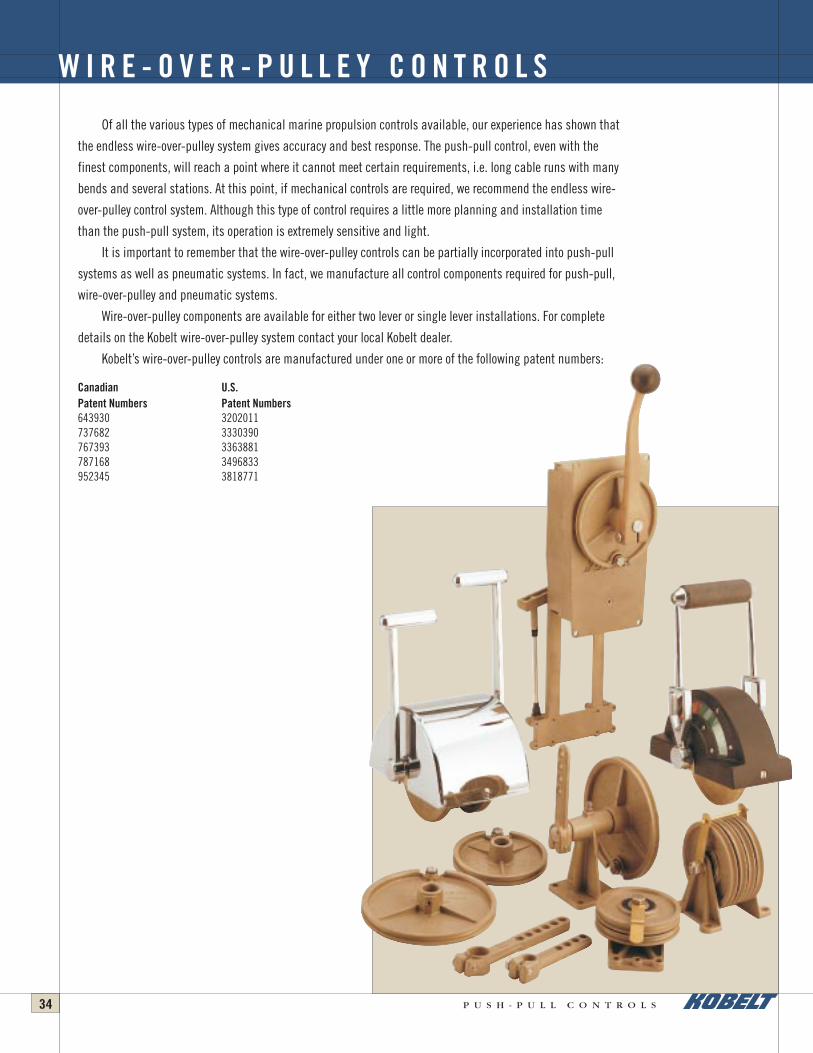
Of all the various types of mechanical marine propulsion controls available, our experience has shown that
the endless wire-over-pulley system gives accuracy and best response. The push-pull control, even with the
finest components, will reach a point where it cannot meet certain requirements, i.e. long cable runs with many
bends and several stations. At this point, if mechanical controls are required, we recommend the endless wire-
over-pulley control system. Although this type of control requires a little more planning and installation time
than the push-pull system, its operation is extremely sensitive and light.
It is important to remember that the wire-over-pulley controls can be partially incorporated into push-pull
systems as well as pneumatic systems. In fact, we manufacture all control components required for push-pull,
wire-over-pulley and pneumatic systems.
Wire-over-pulley components are available for either two lever or single lever installations. For complete
details on the Kobelt wire-over-pulley system contact your local Kobelt dealer.
Kobelt’s wire-over-pulley controls are manufactured under one or more of the following patent numbers:
Canadian U.S. Patent Numbers Patent Numbers643930 3202011737682 3330390767393 3363881787168 3496833952345 3818771
W I R E - O V E R - P U L L E Y C O N T R O L S
Push-Pull Cat REVISED 9/4/03 8:22 AM Page 30

P U S H - P U L L C O N T R O L S 35
Kobelt pneumatic controls are the finest in the industry. We manufacture all components for any type of pneumatic control system.
This control system features a limitless number of control stations. Additional control stations do not affect the performance of the
control system. This means that, regardless of the distance or the force required, the control heads move effortlessly.
The pneumatic control system is one of the most flexible systems we offer. Since the system does not depend on the force you apply
(everything is done by air signals) we can automate and synchronize as much, or as little, of your propulsion equipment as desired. The
control options are almost limitless. We offer propulsion timing packages with, and without, shaft brakes. A timing system will protect your
propulsion equipment. It ensures that the gear box is engaged before you accelerate your engine. The system will allow you to go from full
ahead to full astern without damaging your gear box or stalling your engine.
You will find that the pneumatic system is best suited for vessels anywhere between 50 to 600 feet (15 to 180m). For the ultimate in
styling, flexibility and for fingertip control, contact your nearest Kobelt distributor about Kobelt pneumatic controls.
Kobelt’s pneumatic controls are manufactured under one or more of the following Patent numbers. Further patents pending.
Canadian Patent Numbers:
Canadian U.S. Patent Numbers Patent Numbers828507 3455186922594 3724970923767 3766835928607 3783742932600 3795110936055 3820438939202 3826490947619 3838630964138 3900090964555
P N E U M A T I C C O N T R O L S
Push-Pull Cat REVISED 9/4/03 8:22 AM Page 31

P U S H - P U L L C O N T R O L S36
Kobelt Manufacturing is an innovator when it comes to new steering techniques with boats requiring rudder torques from small boats
up to 160 ton meters. Due to Kobelt’s bronze diecasting capabilities, we are in a position to offer products not available from any other
source in the world. Most manufacturers today make their products in either plastic or aluminium. Kobelt Manufacturing specializes in
bronze and stainless steel at very competitive prices.
Due to our high-tech manufacturing process we are capable of producing a superior product. It is for this reason that we can extend
our usual five-year warranty to steering gear components.
H Y D R A U L I C S T E E R I N G G E A R F O R M A R I N E A P P L I C A T I O N S
7050
7040
7080
7094
7005
7003
7012
Push-Pull Cat REVISED 9/4/03 8:22 AM Page 32

Kobelt ManufacturingHydraulic Steering & Accessories Catalogue
17" x 11" Trim – 17-1/4" x 11-1/4" Bleed — Folds to 8-1/2" x 11"4/C + Gloss VarnishPage 2 – Inside covers
YEL MAG CYAN BLK
3
CONTROL YOUR SHIP WITH COMPLETE SYSTEMS AND COMPONENTS FROM KOBELT MANUFACTURING
1
2
5
4
6
7
8
9
10
1 Steering components up to 320 tonmeter for hydraulicsteering of single and multi-rudder vessels
2 In the aftdeck control station, complete control over allpropulsion and deck machinery.
3 Hydraulic cylinders and control devices for lowering andraising masts, davits for lifeboats, loading ramps etc.
4 Weatherproof controls for outside stations to controlpropulsion and deck machinery.
5 Control components for propulsion and deck machinery, pluselectronic alarm systems and electronic telegraphs.
6 Control for all deck machinery such as anchor and towing winches.
7 Controls for bow thrusters.
8 Control components for any propulsion package, fixed pitch CP propellers, load share and load control.
9 Propeller shaft disk brakes, from small engines up to 50,000 HP.
Control components to control stern thrusters.10
ver since our humble beginnings in 1962, Kobelt Manufacturing
Limited has been committed to manufacturing the finest marine
controls in the world. We stress the importance of quality, precision,
competitive pricing and prompt delivery. Our team of dedicated
production staff is uncompromising in ensuring that we meet the
needs of all our valued customers. Our growing reputation in world
markets is proof of our commitment to highest possible standards.
From our very first line of pneumatic controls we’ve believed in the
simple things—rugged construction, quality materials and prompt
delivery to our customers. Today, the technology has changed, but
our commitment remains the same. From our innovations in electronic
controls to our craftsmanship with bronze and stainless steel, our
products span the oceans of the world to further our reputation as
an international leader in maritime technology.
Kobelt Manufacturing, Surrey, British Columbia, Canada
Kobelt ManufacturingHydraulic Steering & Accessories Catalogue
17" x 11" Trim – 17-1/4" x 11-1/4" Bleed — Folds to 8-1/2" x 11"4/C + Gloss Varnish
Page 1 – Outside covers
YEL MAG CYAN BLK
P U S H - P U L L C O N T RO L SH Y D R A U L I C S T E E R I N G & A C C E S S O R I E S
E L E C T RO N I C C O N T RO L SP N E U M AT I C C O N T RO L S
D I S C B R A K E S
8238 129th Street, Surrey
British Columbia, Canada V3W 0A6
Sales: 604.590.7313 Fax: 604.590.8313
[email protected] www.kobelt.com
WEB 02/04 PRINTED IN CANADA
All Kobelt equipment comes with a 5-year warranty that is the best in the industry. Strict quality control manufacturing and sturdy corrosion-resistant materials ensure trouble-free serviceabove and beyond this generous warranty period.


