
Giga Signs - PTL2 Operation and Programming Version 2.4 Page 1 of 32
PTL2 (Portable Traffic Lights) Operating and Programming
The Programmer Front Panel
N21990
Manufactured by Giga Signs Pty. Ltd. a Quality Management System Approved to
AS/NZS ISO 9001:2008 – Reg. C31071
Giga Signs - PTL2 Operation and Programming Version 2.4 Page 2 of 32
Contents
Pre-Delivery Checks......................................................................................................................................... 3 Overview and Definitions ................................................................................................................................ 4 Joining & Separating PTL2 Trailers ................................................................................................................... 6 On Site Setup and Pack Up .............................................................................................................................. 7
Setting up ................................................................................................................................................ 7 Packing up ............................................................................................................................................... 8
Status Display Mode Key Selector.................................................................................................................... 9 PTL2 Modes of Operation ...............................................................................................................................10
Manual Mode .............................................................................................................................................10
How to Set the Aspect Timing .................................................................................................................12 Vehicle Trigger Mode – (Optional Vehicle Detectors Must Be Fitted) ..........................................................14
Fixed Time (Timer) Mode ...........................................................................................................................15
Two Lane Traffic Control.............................................................................................................................16
Vehicle Trigger 3-Way – (Optional Vehicle Detectors Must Be Fitted) .........................................................17
4 Way Independent Intersection Mode (Version: 2.39+) .................................................................................19 4 Way Independent Operation Modes: ...................................................................................................21
Changing Default Settings ..............................................................................................................................23 Radio Channel Selection .............................................................................................................................23
SMS Reporting (optional) ...........................................................................................................................23
Setting the Phone Number .........................................................................................................................23
Testing the SMS System .............................................................................................................................24
Setting the Plant Number ...........................................................................................................................24
Diagnostic Check Digits (Use this to confirm communication errors) .......................................................24 Setting the Date & Time (Optional) .............................................................................................................25
Typical Values for ‘All Red’ Time .................................................................................................................25
PTL2 Remote Controller (Optional) .............................................................................................................26
PTL2 Remote - Setting the Channel .........................................................................................................26 PTL2 Remote - Setting the Unit Number .................................................................................................26 PTL2 Remote - Operation........................................................................................................................27 PTL2 Remote - Charging ..........................................................................................................................27
Troubleshooting .............................................................................................................................................28 Appendix A.....................................................................................................................................................30
PTL2 Control Codes – Quick Reference Guide .............................................................................................30
Appendix B. PTL2 - Fault Finding ...................................................................................................................31
Please Note: Specifications subject to change without notice
Giga Signs - PTL2 Operation and Programming Version 2.4 Page 3 of 32
Pre-Delivery Checks
The following checks should be performed:
a) Tyre condition & pressure (200 kPa).
b) All wheel nuts tight.
c) Spare wheel (if fitted) secure & locked.
d) Tail light wiring & plugs are in good order and all lights working correctly.
e) Drawbar, joiner bar, towing gear and safety chains are in good order.
f) Hand brake adjusted & functioning properly (if fitted).
g) Jockey wheel and stabilizer legs are in good operating condition.
h) Winches operational and winch cables are in good order.
i) Solar panels are clean.
j) SMS phone number set to contact appropriate person (982 SETUP).
k) SMS system tested for correct operation (997 SETUP).
l) Locks present for battery box (if required).
m) Locks present for controller box (if required).
n) Locks present for wheel locking chains and mast (if required).
o) Light head fully lowered, and mast pin locked into position before relocating the units.
p) Switch on Slave unit, then Master unit. Switch lights into Timer mode, and check the operation of all lights, including rear “red condition” amber lights. This is a lamp check only.
When testing equipment to ensure correct operation it is recommended the units are a minimum of 10m apart.
Giga Signs - PTL2 Operation and Programming Version 2.4 Page 4 of 32
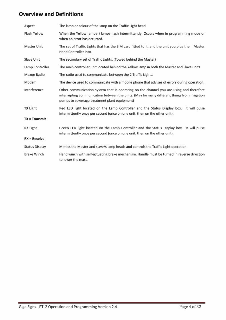
Overview and Definitions
Aspect The lamp or colour of the lamp on the Traffic Light head.
Flash Yellow When the Yellow (amber) lamps flash intermittently. Occurs when in programming mode or
when an error has occurred.
Master Unit The set of Traffic Lights that has the SIM card fitted to it, and the unit you plug the Master
Hand Controller into.
Slave Unit The secondary set of Traffic Lights. (Towed behind the Master)
Lamp Controller The main controller unit located behind the Yellow lamp in both the Master and Slave units.
Maxon Radio The radio used to communicate between the 2 Traffic Lights.
Modem The device used to communicate with a mobile phone that advises of errors during operation.
Interference Other communication system that is operating on the channel you are using and therefore
interrupting communication between the units. (May be many different things from irrigation
pumps to sewerage treatment plant equipment)
TX Light Red LED light located on the Lamp Controller and the Status Display box. It will pulse
intermittently once per second (once on one unit, then on the other unit).
TX = Transmit
RX Light Green LED light located on the Lamp Controller and the Status Display box. It will pulse
intermittently once per second (once on one unit, then on the other unit).
RX = Receive
Status Display Mimics the Master and slave/s lamp heads and controls the Traffic Light operation.
Brake Winch Hand winch with self-actuating brake mechanism. Handle must be turned in reverse direction
to lower the mast.
Giga Signs - PTL2 Operation and Programming Version 2.4 Page 5 of 32
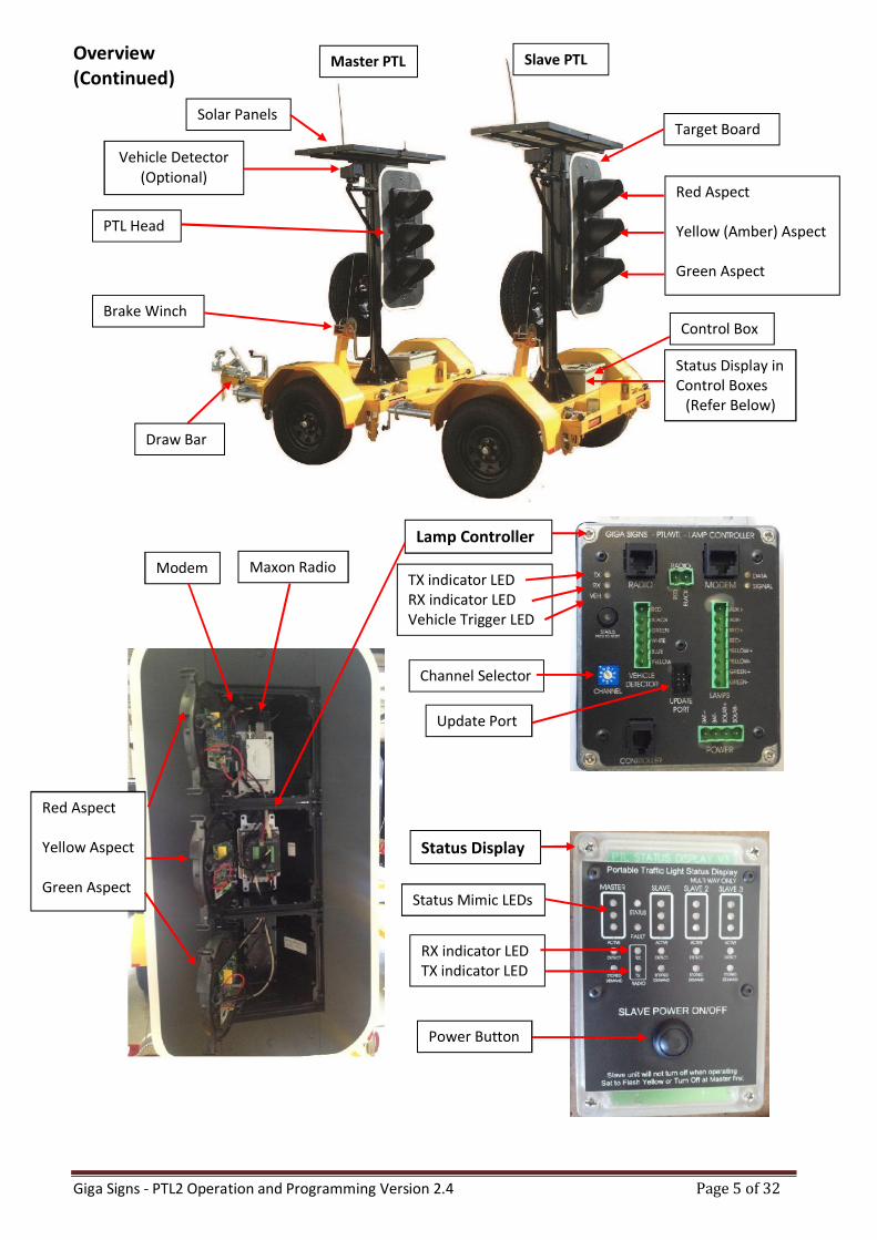
Overview (Continued)
Status Display
Lamp Controller
Maxon Radio
Red Aspect Yellow (Amber) Aspect Green Aspect
Control Box
Status Display in Control Boxes
(Refer Below)
Solar Panels
PTL Head
Brake Winch
Draw Bar
Vehicle Detector (Optional)
Target Board
Red Aspect Yellow Aspect Green Aspect
Channel Selector
TX indicator LED RX indicator LED Vehicle Trigger LED
RX indicator LED TX indicator LED
Status Mimic LEDs
Update Port
Power Button
Modem
Master PTL Slave PTL
Giga Signs - PTL2 Operation and Programming Version 2.4 Page 6 of 32
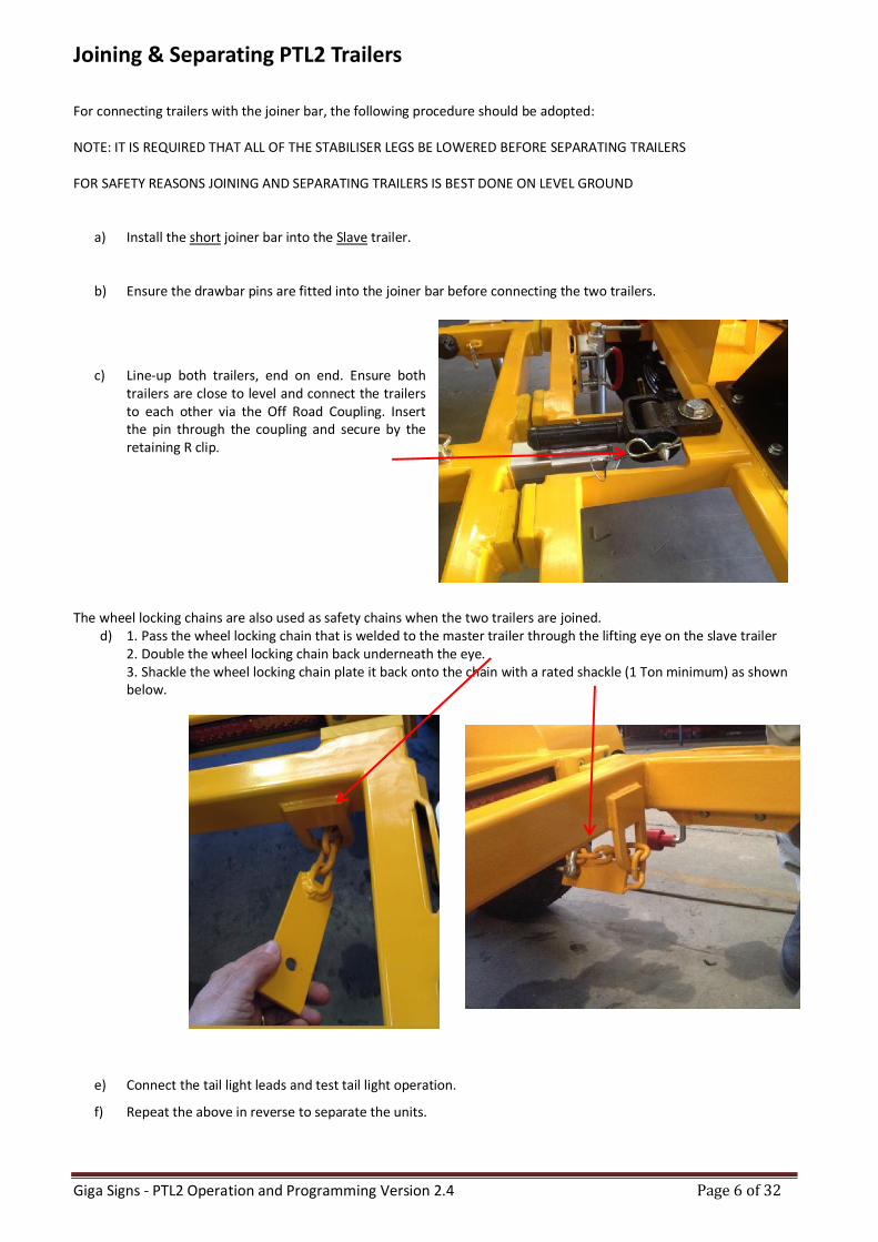
Joining & Separating PTL2 Trailers
For connecting trailers with the joiner bar, the following procedure should be adopted: NOTE: IT IS REQUIRED THAT ALL OF THE STABILISER LEGS BE LOWERED BEFORE SEPARATING TRAILERS FOR SAFETY REASONS JOINING AND SEPARATING TRAILERS IS BEST DONE ON LEVEL GROUND
a) Install the short joiner bar into the Slave trailer.
b) Ensure the drawbar pins are fitted into the joiner bar before connecting the two trailers.
c) Line-up both trailers, end on end. Ensure both trailers are close to level and connect the trailers to each other via the Off Road Coupling. Insert the pin through the coupling and secure by the retaining R clip.
The wheel locking chains are also used as safety chains when the two trailers are joined. d) 1. Pass the wheel locking chain that is welded to the master trailer through the lifting eye on the slave trailer
2. Double the wheel locking chain back underneath the eye. 3. Shackle the wheel locking chain plate it back onto the chain with a rated shackle (1 Ton minimum) as shown below.
e) Connect the tail light leads and test tail light operation.
f) Repeat the above in reverse to separate the units.
Giga Signs - PTL2 Operation and Programming Version 2.4 Page 7 of 32
On Site Setup and Pack Up
Setting up
a) Before removing the PTL2 Slave (THE REAR TRAILER IS REFERED TO AS THE SLAVE UNIT) trailer from the vehicle, establish the final position for the Traffic Lights with a clear view to desired traffic. Ensure that the unit is not in a position where the PTL2 is too close to traffic for adequate safety clearance or where as it may be hit by a vehicle. Further ensure that the unit is not in a position to hinder or endanger pedestrian traffic. If the unit has to be positioned close to the flow of traffic or pedestrians, it is recommended that appropriate safety barriers be utilised.
b) A suitable location also requires the units to be positioned where the solar panels receive direct sun light.
NB. If there are successive overcast days, trees, buildings or other obstacles blocking the sunlight from the solar panels, the battery units will need periodic external charging.
c) Clean the solar panels regularly to ensure no dirt/dust stops the recharge process.
d) If fitted, engage the hand brake before releasing the Slave trailer from the towing vehicle.
e) Remove the tail light cable and safety chains.
f) Move the units to their final position and lower the stabiliser legs.
g) Level the units with the stabiliser legs.
h) If required remove the wheels or use the wheel locking chains to secure them.
i) Disengage mast pin and raise light head up.
j) Lock the safety pin on the mast into position, the mast must be fully raised.
k) Carry out a final check of the unit to ensure it is in a safe position and correctly aligned with the light head facing oncoming traffic.
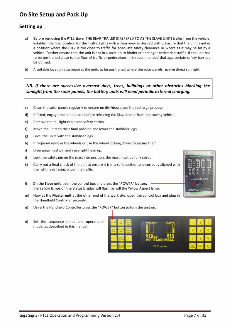
l) On the Slave unit, open the control box and press the “POWER” button, the Yellow lamps on the Status Display will flash, as will the Yellow Aspect lamp.
m) Now at the Master unit at the other end of the work site, open the control box and plug in the Handheld Controller securely.
n) Using the Handheld Controller press the “POWER” button to turn the unit on.
o) Set the sequence times and operational mode, as described in this manual.

Giga Signs - PTL2 Operation and Programming Version 2.4 Page 8 of 32
Packing up
PICK UP THE MASTER UNIT FIRST
a) Turn off the Master PTL2 unit first, by pressing the “POWER” button on the PTL Controller, located in the control box.
To turn off the Slave unit, the system must be in Flash Yellow mode, and then press the “POWER” button on the STATUS DISPLAY unit on the Slave control box.
b) Ensure that the wheels are properly fitted and wheel nuts correctly tightened.
c) Check that the hand brake is engaged (if fitted) and any wheel locks are removed and stowed.
d) Release the mast locking pin and lower the lamp heads.
e) Raise stabiliser legs and swivel into the transport position.
f) Lower the trailer to the towing vehicle (using jockey wheel).
g) Ensure the tow hitch is properly fitted to the tow ball of the towing vehicle and the latch is in the locked position.
h) Connect safety chains – Master unit to the tow vehicle.
i) Connect the 7 pin tail light connecter.
j) Raise and swivel jockey wheel to transport position.
k) It is recommended that the handles for the jockey wheel and stabiliser legs be rotated to “sit” on the trailer frame and not left hanging down.
l) Release hand brake (if fitted).
m) Check tail lights are operating correctly.
n) Check all stabiliser legs and jockey wheel swivels have locked into position correctly.
o) PICK UP THE SLAVE UNIT NEXT.
p) Follow the procedure listed above.
q) Refer to the section “Joining & Separating PTL2 Trailers”.
Giga Signs - PTL2 Operation and Programming Version 2.4 Page 9 of 32
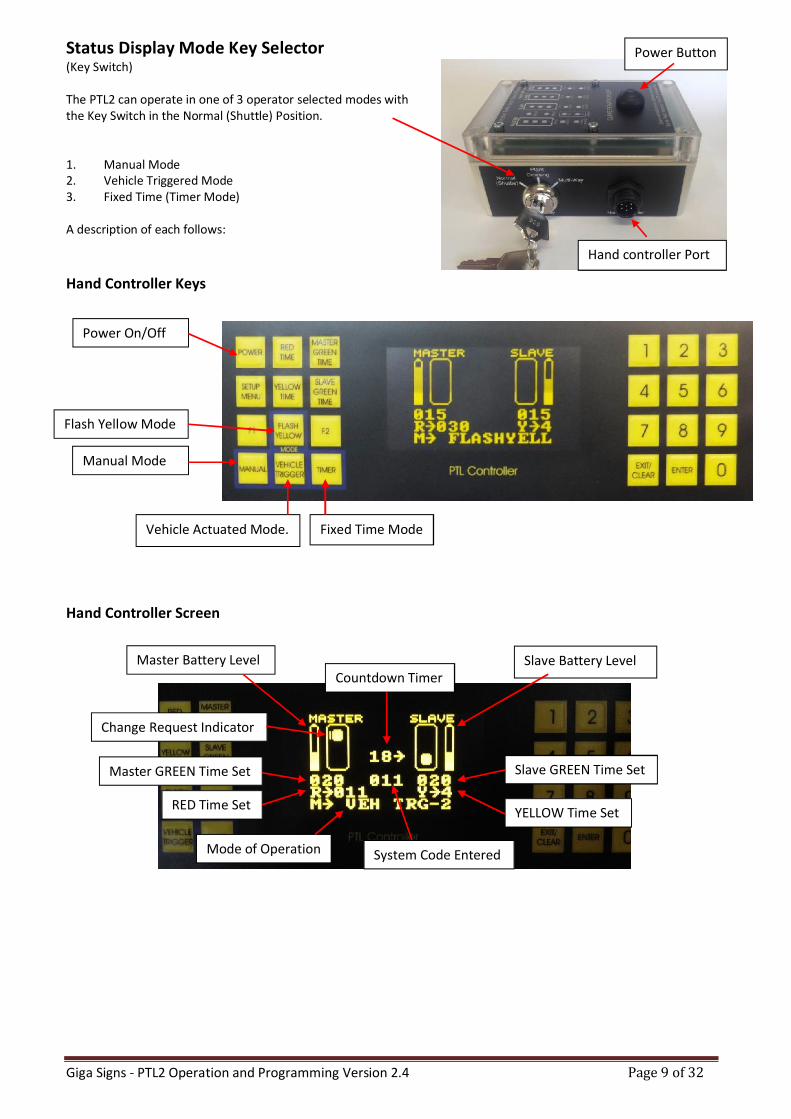
Status Display Mode Key Selector (Key Switch) The PTL2 can operate in one of 3 operator selected modes with the Key Switch in the Normal (Shuttle) Position. 1. Manual Mode 2. Vehicle Triggered Mode 3. Fixed Time (Timer Mode) A description of each follows:
Hand Controller Keys
Hand Controller Screen
Hand controller Port
Flash Yellow Mode
Manual Mode
Vehicle Actuated Mode. Fixed Time Mode
Power On/Off
Slave Battery Level
Slave GREEN Time Set
Master Battery Level
YELLOW Time Set
Change Request Indicator
Master GREEN Time Set
RED Time Set
Mode of Operation
Countdown Timer
System Code Entered
Power Button
Giga Signs - PTL2 Operation and Programming Version 2.4 Page 10 of 32
Press Press = Press
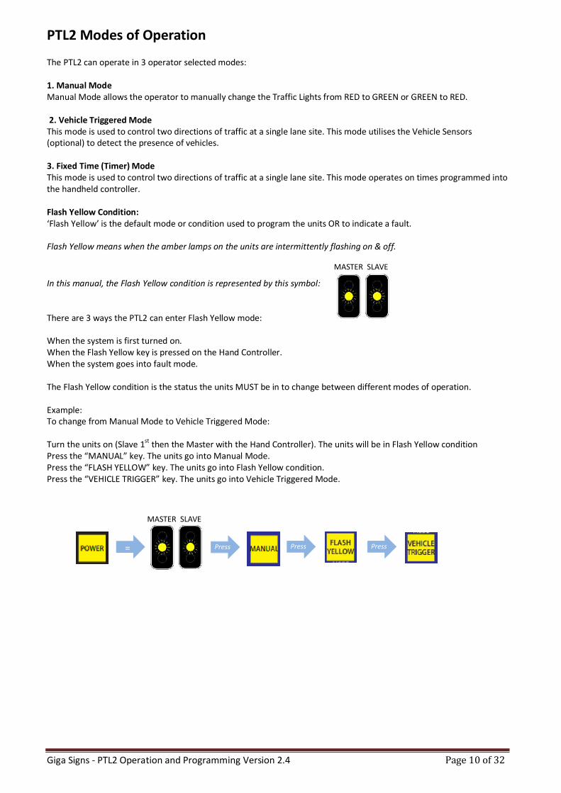
PTL2 Modes of Operation The PTL2 can operate in 3 operator selected modes: 1. Manual Mode Manual Mode allows the operator to manually change the Traffic Lights from RED to GREEN or GREEN to RED. 2. Vehicle Triggered Mode This mode is used to control two directions of traffic at a single lane site. This mode utilises the Vehicle Sensors (optional) to detect the presence of vehicles. 3. Fixed Time (Timer) Mode This mode is used to control two directions of traffic at a single lane site. This mode operates on times programmed into the handheld controller. Flash Yellow Condition: ‘Flash Yellow’ is the default mode or condition used to program the units OR to indicate a fault. Flash Yellow means when the amber lamps on the units are intermittently flashing on & off.
In this manual, the Flash Yellow condition is represented by this symbol: There are 3 ways the PTL2 can enter Flash Yellow mode: When the system is first turned on. When the Flash Yellow key is pressed on the Hand Controller. When the system goes into fault mode. The Flash Yellow condition is the status the units MUST be in to change between different modes of operation. Example: To change from Manual Mode to Vehicle Triggered Mode: Turn the units on (Slave 1st then the Master with the Hand Controller). The units will be in Flash Yellow condition Press the “MANUAL” key. The units go into Manual Mode. Press the “FLASH YELLOW” key. The units go into Flash Yellow condition. Press the “VEHICLE TRIGGER” key. The units go into Vehicle Triggered Mode.
MASTER SLAVE
MASTER SLAVE
Giga Signs - PTL2 Operation and Programming Version 2.4 Page 11 of 32
= Press
Radio Remote
Controller (Optional)
Press =
= Press
= Press
Manual Mode
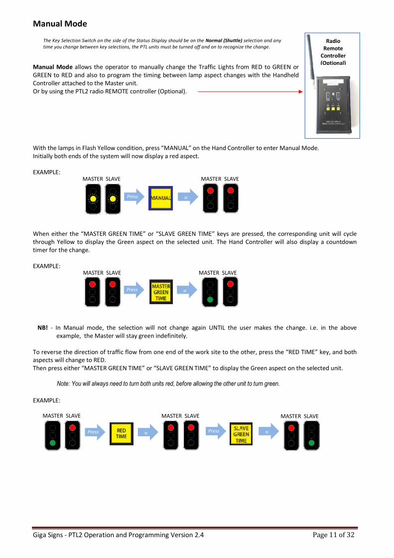
Manual Mode allows the operator to manually change the Traffic Lights from RED to GREEN or GREEN to RED and also to program the timing between lamp aspect changes with the Handheld Controller attached to the Master unit. Or by using the PTL2 radio REMOTE controller (Optional). With the lamps in Flash Yellow condition, press “MANUAL” on the Hand Controller to enter Manual Mode. Initially both ends of the system will now display a red aspect. EXAMPLE:
When either the “MASTER GREEN TIME” or “SLAVE GREEN TIME” keys are pressed, the corresponding unit will cycle through Yellow to display the Green aspect on the selected unit. The Hand Controller will also display a countdown timer for the change. EXAMPLE:
NB! - In Manual mode, the selection will not change again UNTIL the user makes the change. i.e. in the above example, the Master will stay green indefinitely.
To reverse the direction of traffic flow from one end of the work site to the other, press the “RED TIME” key, and both aspects will change to RED. Then press either “MASTER GREEN TIME” or “SLAVE GREEN TIME” to display the Green aspect on the selected unit.
Note: You will always need to turn both units red, before allowing the other unit to turn green.
EXAMPLE:
The Key Selection Switch on the side of the Status Display should be on the Normal (Shuttle) selection and any time you change between key selections, the PTL units must be turned off and on to recognize the change.
MASTER SLAVE MASTER SLAVE
MASTER SLAVE MASTER SLAVE
MASTER SLAVE MASTER SLAVE
MASTER SLAVE
Giga Signs - PTL2 Operation and Programming Version 2.4 Page 12 of 32
How to Set the Aspect Timing
Length of time between aspect changes can be customised to suit different applications.
Times should be set up whilst unit is in the Flash Yellow condition. Units will be in Flash Yellow condition upon turning on or by pressing the “FLASH YELLOW” key.
1. Once in Flash Yellow condition, press the “EXIT/CLEAR” key to clear previously stored times.
2. Key in the required Red time followed by the “RED TIME” key to set the time.
3. Enter the required Green time for the Master unit, followed by the “MASTER GREEN TIME” key to set.
4. Enter the required Green time for the Slave unit, followed by the “SLAVE GREEN TIME” key to set.
5. Set Amber time to 4 seconds for speed zones <80km per hour - OR - 5 seconds for >80km per hour.
Set the Amber time required by entering the seconds and pressing the “YELLOW TIME” key to set.
Note: Minimum RED time that can be set is 6 seconds up to a Maximum of 150 seconds. Minimum GREEN time that can be set is 10 seconds up to a Maximum of 150 seconds. Minimum AMBER time that can be set is restricted to either 4 or 5 seconds.
Once times have all been entered, press the “MANUAL” key. The lights will now run in the manual mode. To exit this mode, press the “Flash Yellow” button.
Note: Times can also be changed whilst lights are running (not in Flash Yellow condition) by pressing the “ENTER”
key then the required time and destination key within five seconds. Press the below sequence of keys within 5 seconds while the lights are running:
1. Press “ENTER” Key
2. Enter the desired time (in seconds) using the number keys.
3. Press the key for the time you wish to set (e.g. Red, Yellow, Master Green or Slave Green).
For more information on setting RED TIME, refer to ‘Normal Values for ‘All Red’ Time’ in this manual.
Giga Signs - PTL2 Operation and Programming Version 2.4 Page 13 of 32
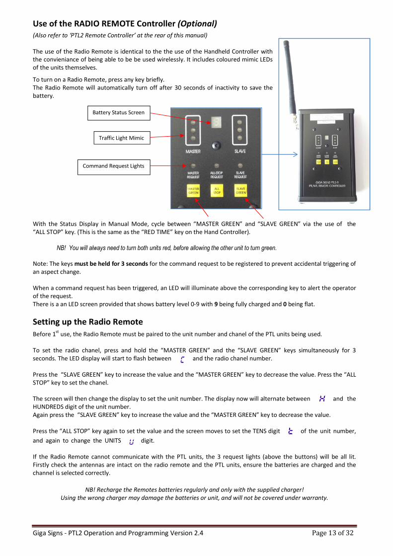
Use of the RADIO REMOTE Controller (Optional) (Also refer to ‘PTL2 Remote Controller’ at the rear of this manual) The use of the Radio Remote is identical to the the use of the Handheld Controller with the convieniance of being able to be be used wirelessly. It includes coloured mimic LEDs of the units themselves.
To turn on a Radio Remote, press any key briefly. The Radio Remote will automatically turn off after 30 seconds of inactivity to save the battery.
With the Status Display in Manual Mode, cycle between “MASTER GREEN” and “SLAVE GREEN” via the use of the “ALL STOP” key. (This is the same as the “RED TIME” key on the Hand Controller).
NB! You will always need to turn both units red, before allowing the other unit to turn green. Note: The keys must be held for 3 seconds for the command request to be registered to prevent accidental triggering of an aspect change. When a command request has been triggered, an LED will illuminate above the corresponding key to alert the operator of the request. There is a an LED screen provided that shows battery level 0-9 with 9 being fully charged and 0 being flat.
Setting up the Radio Remote
Before 1st use, the Radio Remote must be paired to the unit number and chanel of the PTL units being used. To set the radio chanel, press and hold the “MASTER GREEN” and the “SLAVE GREEN” keys simultaneously for 3 seconds. The LED display will start to flash between and the radio chanel number. Press the “SLAVE GREEN” key to increase the value and the “MASTER GREEN” key to decrease the value. Press the “ALL STOP” key to set the chanel. The screen will then change the display to set the unit number. The display now will alternate between and the HUNDREDS digit of the unit number. Again press the “SLAVE GREEN” key to increase the value and the “MASTER GREEN” key to decrease the value. Press the “ALL STOP” key again to set the value and the screen moves to set the TENS digit of the unit number,
and again to change the UNITS digit. If the Radio Remote cannot communicate with the PTL units, the 3 request lights (above the buttons) will be all lit. Firstly check the antennas are intact on the radio remote and the PTL units, ensure the batteries are charged and the channel is selected correctly.
NB! Recharge the Remotes batteries regularly and only with the supplied charger!
Using the wrong charger may damage the batteries or unit, and will not be covered under warranty.
Command Request Lights
Battery Status Screen
Traffic Light Mimic
Giga Signs - PTL2 Operation and Programming Version 2.4 Page 14 of 32
Press Press Press Press
Press Press Press
MASTER SLAVE
Vehicle Trigger Mode – (Optional Vehicle Detectors Must Be Fitted)
Use this mode to control two directions of traffic at a single lane site. This mode utilises the Vehicle Sensors (optional) to detect the presence of a vehicle. The mode operates on times programmed into the PTL2 Handheld Controller. After an initial cycle of each signal based on the programmed times, both lights will remain on Red UNTIL the sensor detects the presence of a vehicle. The unit that detected the vehicle will turn to Green (provided the other unit is in the Red status). The times are displayed on the Handheld Controller LED display. The presence of a vehicle is indicated by an up arrow the top of the Handheld Controller screen next to the relevant unit status display. When vehicles are detected at one end of the system only, the system will automatically extend the Green time until a vehicle is detected at the other end, or no further vehicles are detected. Times between aspect changes can be custom programmed in the Flash Yellow mode or by pressing the ENTER key then the required time and destination key (within five seconds) during operation of the lights. Refer to “How to Set the Aspect Timing” in this Manual. Note: Amber time should be set to 4 seconds for speed zones <80km per hour - OR - 5 seconds for >80km per hour. Once required times have been entered, press the “VEHICLE TRIGGER” key to activate. The lights will now run in the Vehicle Trigger mode. To EXIT this mode, press the “Flash Yellow” button.
Vehicle Trigger Mode - Manual Override (Vehicle Trigger-2)
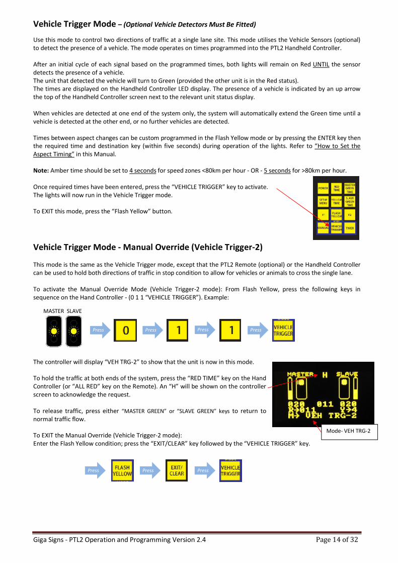
This mode is the same as the Vehicle Trigger mode, except that the PTL2 Remote (optional) or the Handheld Controller can be used to hold both directions of traffic in stop condition to allow for vehicles or animals to cross the single lane. To activate the Manual Override Mode (Vehicle Trigger-2 mode): From Flash Yellow, press the following keys in sequence on the Hand Controller - (0 1 1 “VEHICLE TRIGGER”). Example:
The controller will display “VEH TRG-2” to show that the unit is now in this mode. To hold the traffic at both ends of the system, press the “RED TIME” key on the Hand Controller (or “ALL RED” key on the Remote). An “H” will be shown on the controller screen to acknowledge the request. To release traffic, press either “MASTER GREEN” or “SLAVE GREEN” keys to return to normal traffic flow. To EXIT the Manual Override (Vehicle Trigger-2 mode): Enter the Flash Yellow condition; press the “EXIT/CLEAR” key followed by the “VEHICLE TRIGGER” key.
Mode- VEH TRG-2
Giga Signs - PTL2 Operation and Programming Version 2.4 Page 15 of 32
Press Press Press Press
MASTER SLAVE
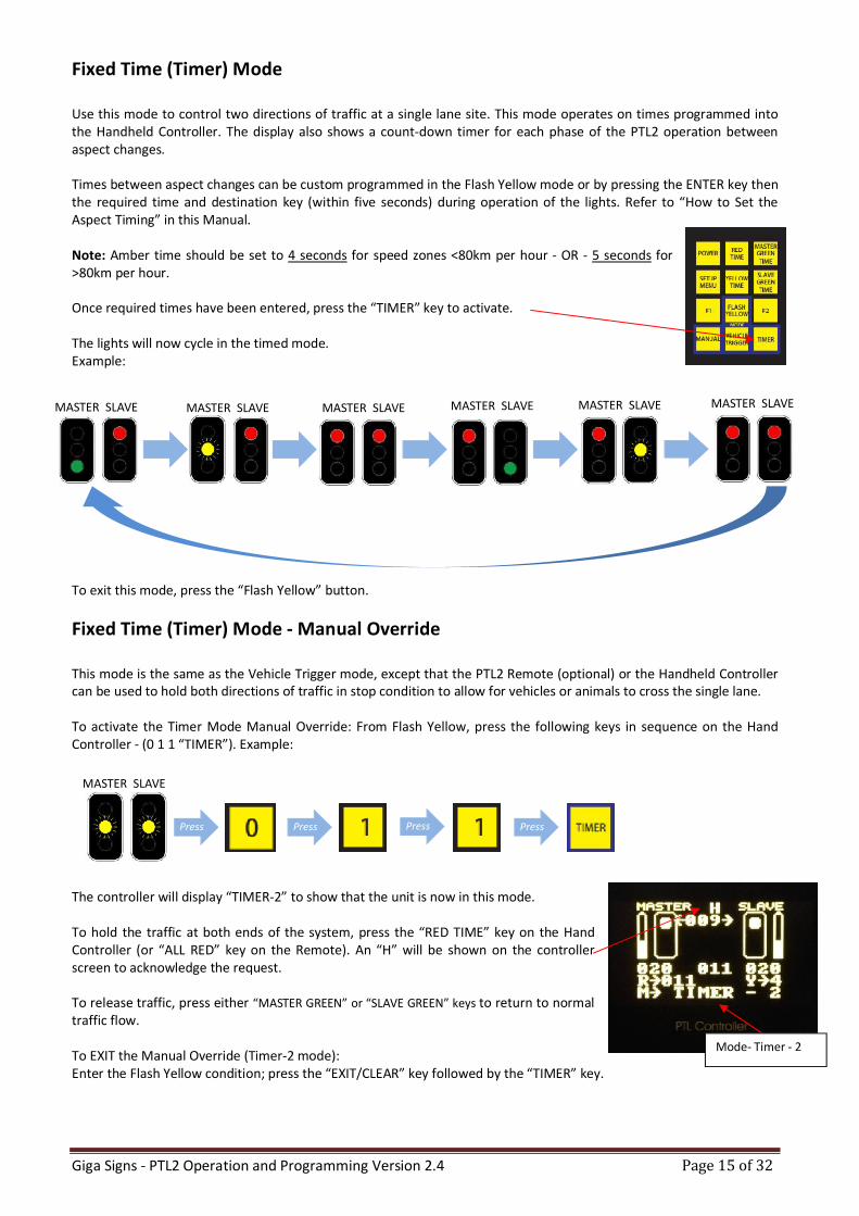
Fixed Time (Timer) Mode
Use this mode to control two directions of traffic at a single lane site. This mode operates on times programmed into the Handheld Controller. The display also shows a count-down timer for each phase of the PTL2 operation between aspect changes. Times between aspect changes can be custom programmed in the Flash Yellow mode or by pressing the ENTER key then the required time and destination key (within five seconds) during operation of the lights. Refer to “How to Set the Aspect Timing” in this Manual. Note: Amber time should be set to 4 seconds for speed zones <80km per hour - OR - 5 seconds for >80km per hour. Once required times have been entered, press the “TIMER” key to activate. The lights will now cycle in the timed mode. Example:
To exit this mode, press the “Flash Yellow” button.
Fixed Time (Timer) Mode - Manual Override
This mode is the same as the Vehicle Trigger mode, except that the PTL2 Remote (optional) or the Handheld Controller can be used to hold both directions of traffic in stop condition to allow for vehicles or animals to cross the single lane. To activate the Timer Mode Manual Override: From Flash Yellow, press the following keys in sequence on the Hand Controller - (0 1 1 “TIMER”). Example:
The controller will display “TIMER-2” to show that the unit is now in this mode. To hold the traffic at both ends of the system, press the “RED TIME” key on the Hand Controller (or “ALL RED” key on the Remote). An “H” will be shown on the controller screen to acknowledge the request. To release traffic, press either “MASTER GREEN” or “SLAVE GREEN” keys to return to normal traffic flow. To EXIT the Manual Override (Timer-2 mode): Enter the Flash Yellow condition; press the “EXIT/CLEAR” key followed by the “TIMER” key.
MASTER SLAVE MASTER SLAVE MASTER SLAVE MASTER SLAVE MASTER SLAVE MASTER SLAVE
Mode- Timer - 2
Giga Signs - PTL2 Operation and Programming Version 2.4 Page 16 of 32
Press Press Press Press
MASTER SLAVE
=
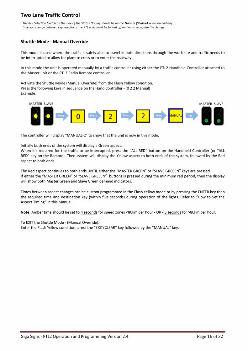
Two Lane Traffic Control
Shuttle Mode - Manual Override This mode is used where the traffic is safely able to travel in both directions through the work site and traffic needs to be interrupted to allow for plant to cross or to enter the roadway. In this mode the unit is operated manually by a traffic controller using either the PTL2 Handheld Controller attached to the Master unit or the PTL2 Radio Remote controller. Activate the Shuttle Mode (Manual Override) from the Flash Yellow condition. Press the following keys in sequence on the Hand Controller - (0 2 2 Manual) Example:
The controller will display “MANUAL-2” to show that the unit is now in this mode. Initially both ends of the system will display a Green aspect. When it’s required for the traffic to be interrupted, press the “ALL RED” button on the Handheld Controller (or “ALL RED” key on the Remote). Then system will display the Yellow aspect to both ends of the system, followed by the Red aspect to both ends. The Red aspect continues to both ends UNTIL either the “MASTER GREEN” or “SLAVE GREEEN” keys are pressed. If either the “MASTER GREEN” or “SLAVE GREEEN” buttons is pressed during the minimum red period, then the display will show both Master Green and Slave Green demand indicators.
Times between aspect changes can be custom programmed in the Flash Yellow mode or by pressing the ENTER key then the required time and destination key (within five seconds) during operation of the lights. Refer to “How to Set the Aspect Timing” in this Manual. Note: Amber time should be set to 4 seconds for speed zones <80km per hour - OR - 5 seconds for >80km per hour. To EXIT the Shuttle Mode - (Manual Override): Enter the Flash Yellow condition; press the “EXIT/CLEAR” key followed by the “MANUAL” key.
The Key Selection Switch on the side of the Status Display should be on the Normal (Shuttle) selection and any time you change between key selections, the PTL units must be turned off and on to recognize the change.
MASTER SLAVE
Giga Signs - PTL2 Operation and Programming Version 2.4 Page 17 of 32
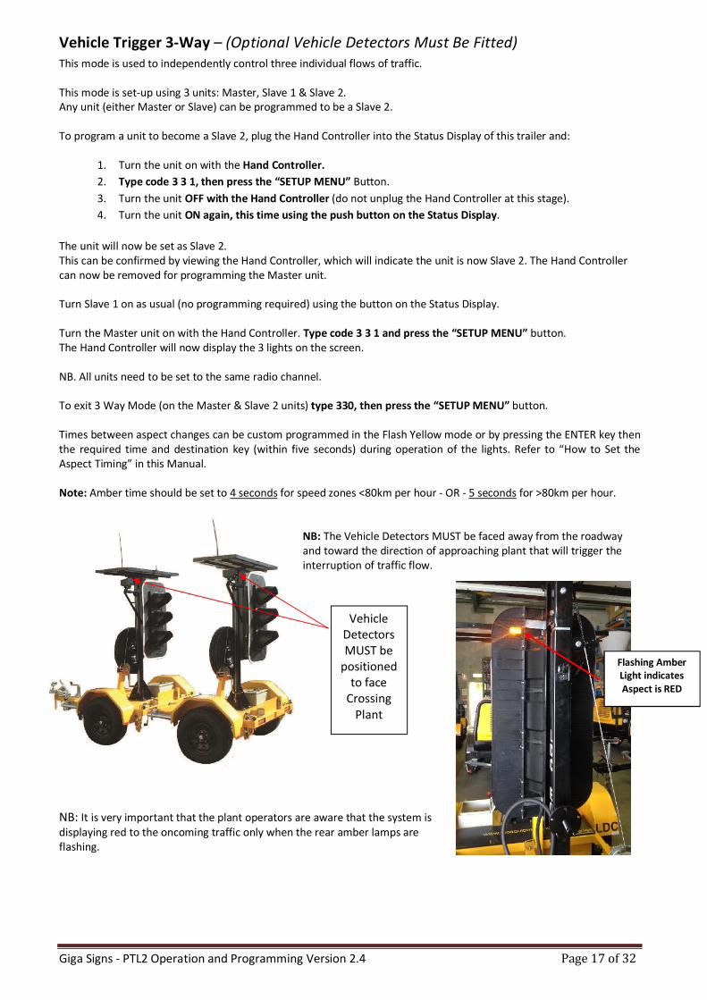
Vehicle Detectors MUST be
positioned to face
Crossing Plant
Vehicle Trigger 3-Way – (Optional Vehicle Detectors Must Be Fitted) This mode is used to independently control three individual flows of traffic. This mode is set-up using 3 units: Master, Slave 1 & Slave 2. Any unit (either Master or Slave) can be programmed to be a Slave 2. To program a unit to become a Slave 2, plug the Hand Controller into the Status Display of this trailer and:
1. Turn the unit on with the Hand Controller.
2. Type code 3 3 1, then press the “SETUP MENU” Button.
3. Turn the unit OFF with the Hand Controller (do not unplug the Hand Controller at this stage).
4. Turn the unit ON again, this time using the push button on the Status Display.
The unit will now be set as Slave 2. This can be confirmed by viewing the Hand Controller, which will indicate the unit is now Slave 2. The Hand Controller can now be removed for programming the Master unit. Turn Slave 1 on as usual (no programming required) using the button on the Status Display. Turn the Master unit on with the Hand Controller. Type code 3 3 1 and press the “SETUP MENU” button. The Hand Controller will now display the 3 lights on the screen. NB. All units need to be set to the same radio channel. To exit 3 Way Mode (on the Master & Slave 2 units) type 330, then press the “SETUP MENU” button. Times between aspect changes can be custom programmed in the Flash Yellow mode or by pressing the ENTER key then the required time and destination key (within five seconds) during operation of the lights. Refer to “How to Set the Aspect Timing” in this Manual. Note: Amber time should be set to 4 seconds for speed zones <80km per hour - OR - 5 seconds for >80km per hour.
NB: The Vehicle Detectors MUST be faced away from the roadway and toward the direction of approaching plant that will trigger the interruption of traffic flow.
NB: It is very important that the plant operators are aware that the system is displaying red to the oncoming traffic only when the rear amber lamps are flashing.
Flashing Amber Light indicates Aspect is RED
Giga Signs - PTL2 Operation and Programming Version 2.4 Page 18 of 32
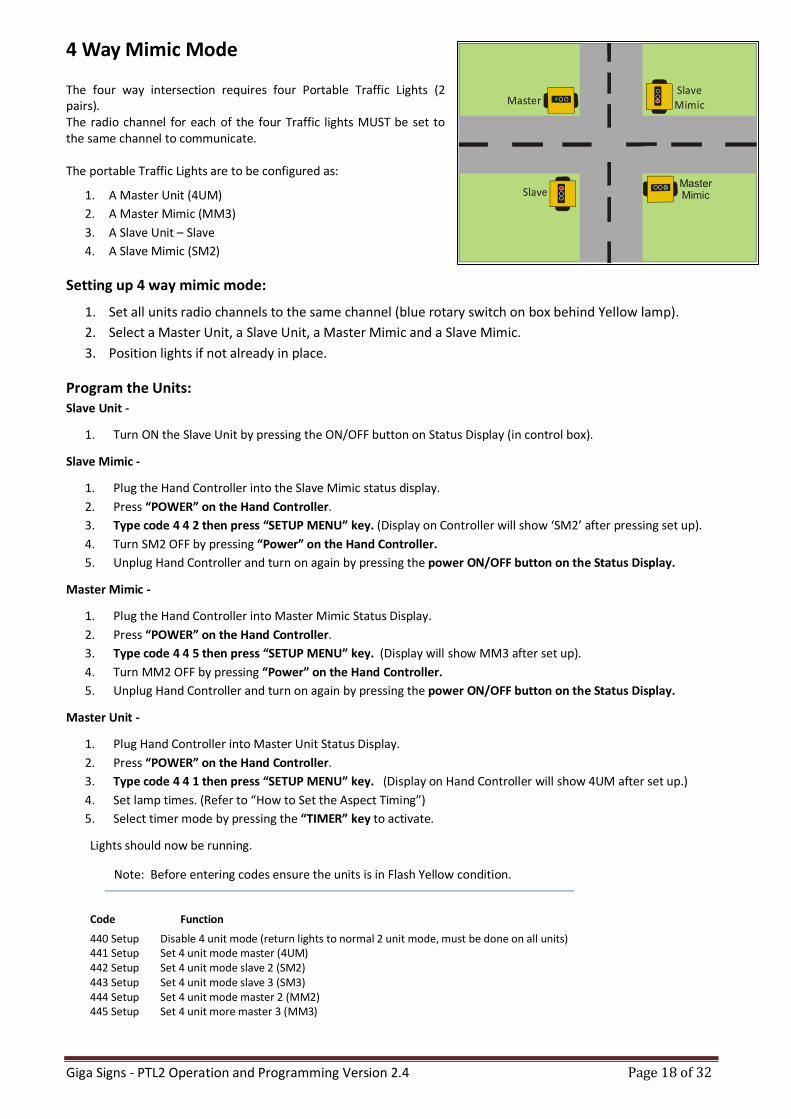
4 Way Mimic Mode
The four way intersection requires four Portable Traffic Lights (2 pairs). The radio channel for each of the four Traffic lights MUST be set to the same channel to communicate. The portable Traffic Lights are to be configured as:
1. A Master Unit (4UM)
2. A Master Mimic (MM3)
3. A Slave Unit – Slave
4. A Slave Mimic (SM2)
Setting up 4 way mimic mode:
1. Set all units radio channels to the same channel (blue rotary switch on box behind Yellow lamp).
2. Select a Master Unit, a Slave Unit, a Master Mimic and a Slave Mimic.
3. Position lights if not already in place.
Program the Units: Slave Unit -
1. Turn ON the Slave Unit by pressing the ON/OFF button on Status Display (in control box).
Slave Mimic -
1. Plug the Hand Controller into the Slave Mimic status display.
2. Press “POWER” on the Hand Controller.
3. Type code 4 4 2 then press “SETUP MENU” key. (Display on Controller will show ‘SM2’ after pressing set up).
4. Turn SM2 OFF by pressing “Power” on the Hand Controller.
5. Unplug Hand Controller and turn on again by pressing the power ON/OFF button on the Status Display.
Master Mimic -
1. Plug the Hand Controller into Master Mimic Status Display.
2. Press “POWER” on the Hand Controller.
3. Type code 4 4 5 then press “SETUP MENU” key. (Display will show MM3 after set up).
4. Turn MM2 OFF by pressing “Power” on the Hand Controller.
5. Unplug Hand Controller and turn on again by pressing the power ON/OFF button on the Status Display.
Master Unit -
1. Plug Hand Controller into Master Unit Status Display.
2. Press “POWER” on the Hand Controller.
3. Type code 4 4 1 then press “SETUP MENU” key. (Display on Hand Controller will show 4UM after set up.)
4. Set lamp times. (Refer to “How to Set the Aspect Timing”)
5. Select timer mode by pressing the “TIMER” key to activate.
Lights should now be running.
Note: Before entering codes ensure the units is in Flash Yellow condition.
Code Function
440 Setup Disable 4 unit mode (return lights to normal 2 unit mode, must be done on all units) 441 Setup Set 4 unit mode master (4UM) 442 Setup Set 4 unit mode slave 2 (SM2) 443 Setup Set 4 unit mode slave 3 (SM3) 444 Setup Set 4 unit mode master 2 (MM2) 445 Setup Set 4 unit more master 3 (MM3)
Slave MimicMaster
SlaveMaster Mimic
Giga Signs - PTL2 Operation and Programming Version 2.4 Page 19 of 32
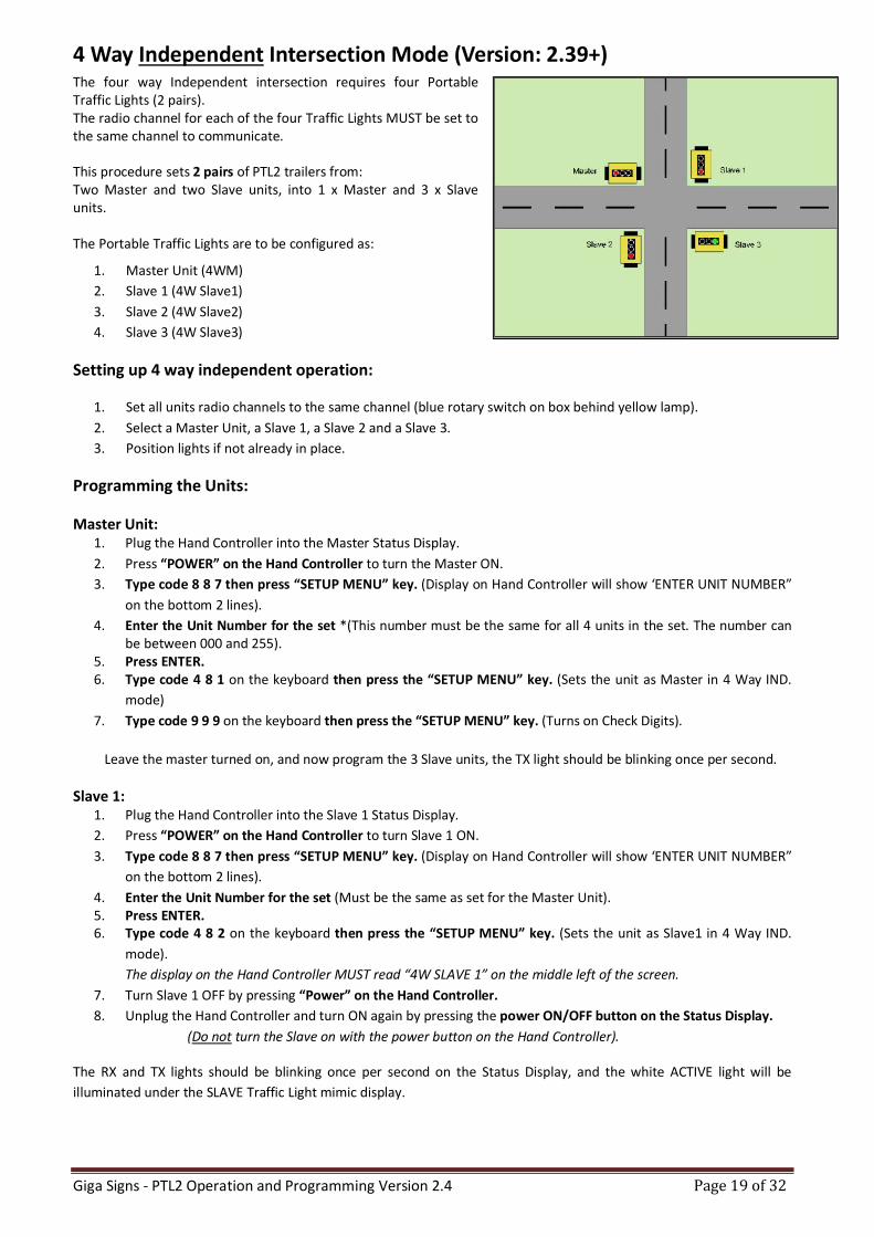
4 Way Independent Intersection Mode (Version: 2.39+) The four way Independent intersection requires four Portable Traffic Lights (2 pairs). The radio channel for each of the four Traffic Lights MUST be set to the same channel to communicate. This procedure sets 2 pairs of PTL2 trailers from: Two Master and two Slave units, into 1 x Master and 3 x Slave units. The Portable Traffic Lights are to be configured as:
1. Master Unit (4WM)
2. Slave 1 (4W Slave1)
3. Slave 2 (4W Slave2)
4. Slave 3 (4W Slave3)
Setting up 4 way independent operation:
1. Set all units radio channels to the same channel (blue rotary switch on box behind yellow lamp).
2. Select a Master Unit, a Slave 1, a Slave 2 and a Slave 3.
3. Position lights if not already in place.
Programming the Units:
Master Unit: 1. Plug the Hand Controller into the Master Status Display.
2. Press “POWER” on the Hand Controller to turn the Master ON.
3. Type code 8 8 7 then press “SETUP MENU” key. (Display on Hand Controller will show ‘ENTER UNIT NUMBER”
on the bottom 2 lines).
4. Enter the Unit Number for the set *(This number must be the same for all 4 units in the set. The number can be between 000 and 255).
5. Press ENTER. 6. Type code 4 8 1 on the keyboard then press the “SETUP MENU” key. (Sets the unit as Master in 4 Way IND.
mode)
7. Type code 9 9 9 on the keyboard then press the “SETUP MENU” key. (Turns on Check Digits).
Leave the master turned on, and now program the 3 Slave units, the TX light should be blinking once per second.
Slave 1: 1. Plug the Hand Controller into the Slave 1 Status Display.
2. Press “POWER” on the Hand Controller to turn Slave 1 ON.
3. Type code 8 8 7 then press “SETUP MENU” key. (Display on Hand Controller will show ‘ENTER UNIT NUMBER”
on the bottom 2 lines).
4. Enter the Unit Number for the set (Must be the same as set for the Master Unit). 5. Press ENTER. 6. Type code 4 8 2 on the keyboard then press the “SETUP MENU” key. (Sets the unit as Slave1 in 4 Way IND.
mode).
The display on the Hand Controller MUST read “4W SLAVE 1” on the middle left of the screen.
7. Turn Slave 1 OFF by pressing “Power” on the Hand Controller.
8. Unplug the Hand Controller and turn ON again by pressing the power ON/OFF button on the Status Display.
(Do not turn the Slave on with the power button on the Hand Controller).
The RX and TX lights should be blinking once per second on the Status Display, and the white ACTIVE light will be
illuminated under the SLAVE Traffic Light mimic display.
Giga Signs - PTL2 Operation and Programming Version 2.4 Page 20 of 32
Slaves 2 and 3:
The process is exactly the same for programming Slave 2 and Slave 3 as Slave 1,
EXCEPT that for Slave 2, the code to be entered is 483 (not 482) and the code for Slave 3 is 484.
Slave 2 MUST show “4W SLAVE 2” on the screen when connected and
Slave 3 MUST show “4W SLAVE 3” on the screen when connected.
Press “TIMER” key to begin operation.
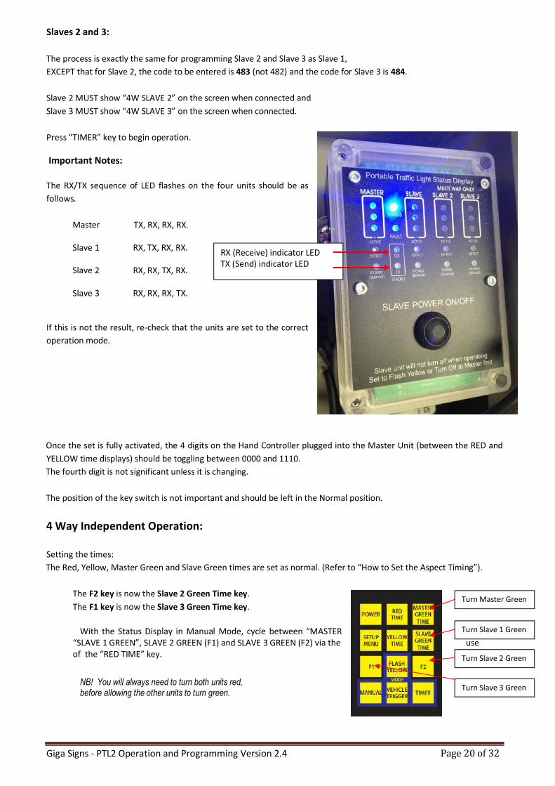
Important Notes:
The RX/TX sequence of LED flashes on the four units should be as
follows.
Master TX, RX, RX, RX. Slave 1 RX, TX, RX, RX. Slave 2 RX, RX, TX, RX.
Slave 3 RX, RX, RX, TX.
If this is not the result, re-check that the units are set to the correct
operation mode.
Once the set is fully activated, the 4 digits on the Hand Controller plugged into the Master Unit (between the RED and
YELLOW time displays) should be toggling between 0000 and 1110.
The fourth digit is not significant unless it is changing.
The position of the key switch is not important and should be left in the Normal position.
4 Way Independent Operation:
Setting the times:
The Red, Yellow, Master Green and Slave Green times are set as normal. (Refer to “How to Set the Aspect Timing”).
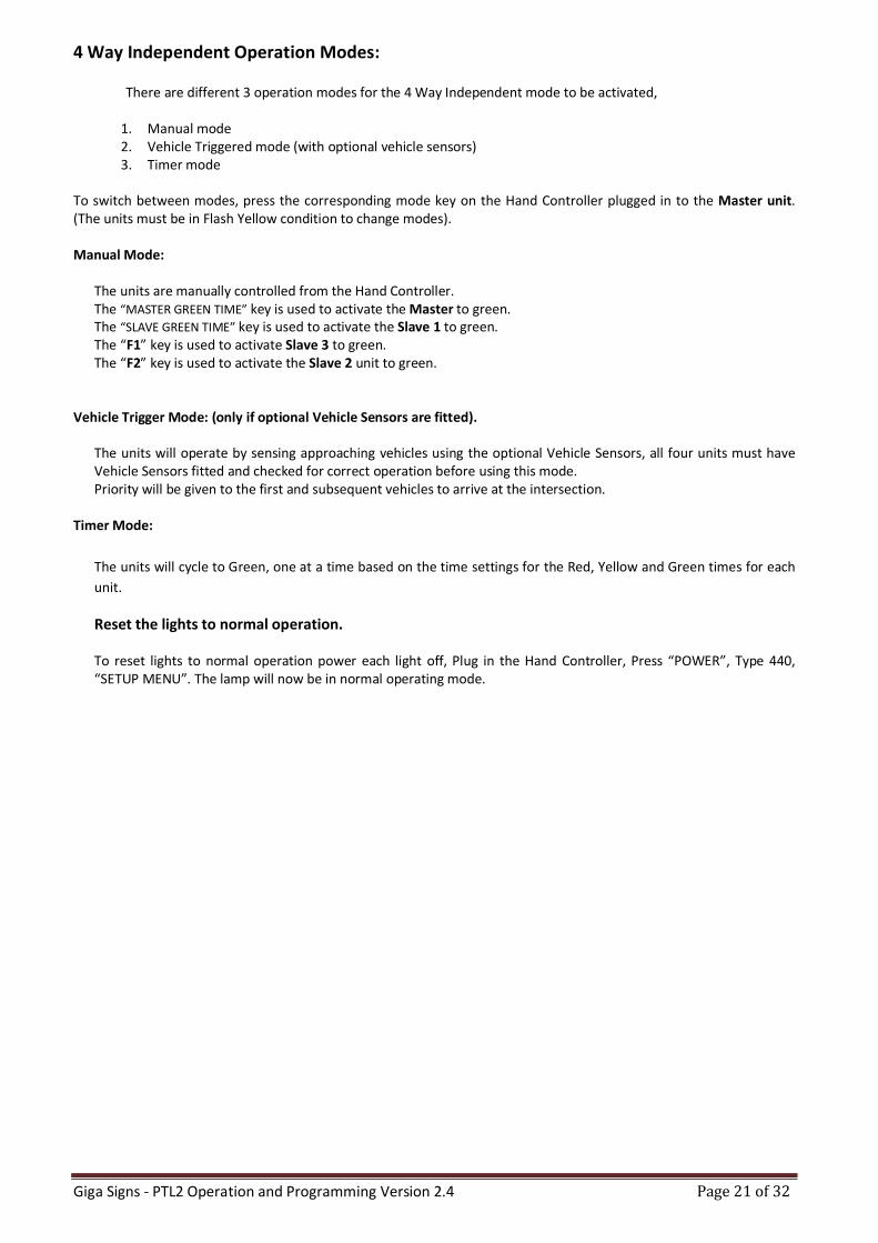
The F2 key is now the Slave 2 Green Time key.
The F1 key is now the Slave 3 Green Time key.
With the Status Display in Manual Mode, cycle between “MASTER GREEN”
“SLAVE 1 GREEN”, SLAVE 2 GREEN (F1) and SLAVE 3 GREEN (F2) via the use of the “RED TIME” key.
NB! You will always need to turn both units red, before allowing the other units to turn green.
RX (Receive) indicator LED TX (Send) indicator LED
Turn Master Green
Turn Slave 2 Green
Turn Slave 1 Green
Turn Slave 3 Green
Giga Signs - PTL2 Operation and Programming Version 2.4 Page 21 of 32
4 Way Independent Operation Modes: There are different 3 operation modes for the 4 Way Independent mode to be activated,
1. Manual mode 2. Vehicle Triggered mode (with optional vehicle sensors) 3. Timer mode
To switch between modes, press the corresponding mode key on the Hand Controller plugged in to the Master unit. (The units must be in Flash Yellow condition to change modes). Manual Mode:
The units are manually controlled from the Hand Controller. The “MASTER GREEN TIME” key is used to activate the Master to green. The “SLAVE GREEN TIME” key is used to activate the Slave 1 to green. The “F1” key is used to activate Slave 3 to green. The “F2” key is used to activate the Slave 2 unit to green.
Vehicle Trigger Mode: (only if optional Vehicle Sensors are fitted).
The units will operate by sensing approaching vehicles using the optional Vehicle Sensors, all four units must have Vehicle Sensors fitted and checked for correct operation before using this mode. Priority will be given to the first and subsequent vehicles to arrive at the intersection.
Timer Mode:
The units will cycle to Green, one at a time based on the time settings for the Red, Yellow and Green times for each
unit.
Reset the lights to normal operation. To reset lights to normal operation power each light off, Plug in the Hand Controller, Press “POWER”, Type 440, “SETUP MENU”. The lamp will now be in normal operating mode.
Giga Signs - PTL2 Operation and Programming Version 2.4 Page 22 of 32
To set a time: (all times are set from the Master Unit)
Times should be set up whilst unit is in the Flash Yellow condition.
1. Once in Flash Yellow condition, press the “EXIT/CLEAR” key to clear previously stored times.
2. Key in the required Red time followed by the “RED TIME” key to set the time.
3. Enter the required Green time for the Master unit, followed by the “MASTER GREEN TIME” key to set.
4. Enter the required Green time for the Slave unit, followed by the “SLAVE GREEN TIME” key to set.
5. Set Amber time to 4 seconds for speed zones <80km per hour - OR - 5 seconds for >80km per hour. Set the Amber time required by entering the seconds and pressing the “YELLOW TIME” key to set.
Once times have all been entered, press the “MANUAL” key. The lights will now run in the manual mode. To exit this mode, press the “Flash Yellow” button.
Note: Minimum RED time that can be set is 6 seconds up to a Maximum of 150 seconds.
Minimum GREEN time that can be set is 10 seconds up to a Maximum of 150 seconds. Minimum AMBER time that can be set is restricted to either 4 or 5 seconds.
Note: The times for the green light in each of the main and the cross road can be configured to allow a minimum green
time.
Note: Times can also be changed whilst lights are running (not in Flash Yellow condition) by pressing the “ENTER” key then the required time and destination key within five seconds.
Press the below sequence of keys within 5 seconds while the lights are running:
1. Press “ENTER” Key
2. Enter the desired time (in seconds) using the number keys.
3. Press the key for the time you wish to set (e.g. Red, Yellow, Master Green or Slave Green).
Note: The red time key will set the red time for both lights.
The master green time key will set the minimum green time for the Master lights. The slave green time will set the minimum green time for the Slave lights.
Fault Modes If any condition exists that would cause confusion to the approaching traffic or a failure condition exists, the unit will automatically revert to Flash Yellow mode. An SMS message will be sent to the pre-programmed phone number (if the optional SMS system is configured). The bottom line of the Handheld Controller screen will show the failure detected. Rectify the failure and then press the “EXIT /CLEAR” button to clear the fault display.
Giga Signs - PTL2 Operation and Programming Version 2.4 Page 23 of 32
Changing Default Settings
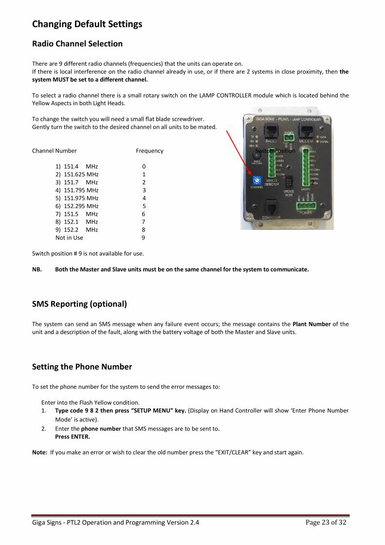
Radio Channel Selection There are 9 different radio channels (frequencies) that the units can operate on. If there is local interference on the radio channel already in use, or if there are 2 systems in close proximity, then the system MUST be set to a different channel. To select a radio channel there is a small rotary switch on the LAMP CONTROLLER module which is located behind the Yellow Aspects in both Light Heads. To change the switch you will need a small flat blade screwdriver. Gently turn the switch to the desired channel on all units to be mated. Channel Number Frequency Switch Position
1) 151.4 MHz 0 2) 151.625 MHz 1 3) 151.7 MHz 2 2 4) 151.795 MHz 3 5) 151.975 MHz 4 6) 152.295 MHz 5 7) 151.5 MHz 6 8) 152.1 MHz 7 9) 152.2 MHz 8 Not in Use 9
Switch position # 9 is not available for use. NB. Both the Master and Slave units must be on the same channel for the system to communicate.
SMS Reporting (optional)
The system can send an SMS message when any failure event occurs; the message contains the Plant Number of the unit and a description of the fault, along with the battery voltage of both the Master and Slave units.
Setting the Phone Number To set the phone number for the system to send the error messages to:
Enter into the Flash Yellow condition. 1. Type code 9 8 2 then press “SETUP MENU” key. (Display on Hand Controller will show ‘Enter Phone Number
Mode’ is active).
2. Enter the phone number that SMS messages are to be sent to. Press ENTER.
Note: If you make an error or wish to clear the old number press the “EXIT/CLEAR” key and start again.
Giga Signs - PTL2 Operation and Programming Version 2.4 Page 24 of 32
Testing the SMS System
To send a test SMS message:
1. Enter into the Flash Yellow condition. 2. Type code 9 9 7 then press “SETUP MENU” key.
3. Press ENTER.
Setting the Plant Number
To set the Plant Number that the PTL2 sends in the SMS messages:
Enter into the Flash Yellow condition. 1. Type code 9 8 1 then press “SETUP MENU” key. (Display on the Hand Controller will show ‘Enter Plant
Number mode’ is active).
2. Enter the Plant Number of the unit. 3. Press ENTER.
Note: If you make an error or wish to clear the old number press the “EXIT/CLEAR” and start again.
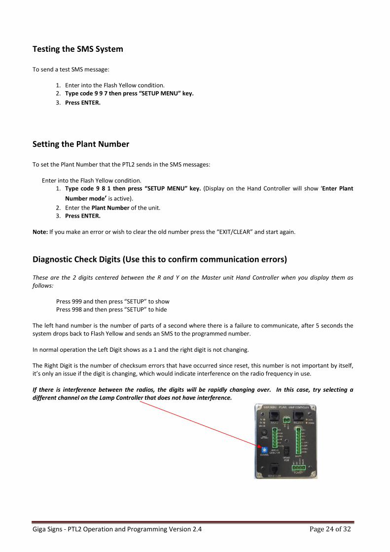
Diagnostic Check Digits (Use this to confirm communication errors)
These are the 2 digits centered between the R and Y on the Master unit Hand Controller when you display them as follows:
Press 999 and then press “SETUP” to show Press 998 and then press “SETUP” to hide
The left hand number is the number of parts of a second where there is a failure to communicate, after 5 seconds the system drops back to Flash Yellow and sends an SMS to the programmed number. In normal operation the Left Digit shows as a 1 and the right digit is not changing. The Right Digit is the number of checksum errors that have occurred since reset, this number is not important by itself, it’s only an issue if the digit is changing, which would indicate interference on the radio frequency in use. If there is interference between the radios, the digits will be rapidly changing over. In this case, try selecting a different channel on the Lamp Controller that does not have interference.
Giga Signs - PTL2 Operation and Programming Version 2.4 Page 25 of 32
Setting the Date & Time (Optional) The clock and calendar should be set whenever the batteries are disconnected or the fuse is removed and replaced for any reason. The unit must be turned on and be in the Flash Yellow mode to allow setting of the time and date. To set the time, press 111 and then press “SETUP MENU”. To set the date, press 112 and then press “SETUP MENU”. The bottom line of the screen will show the current time or date, press the numbered keys to change the digit under the cursor block. The time is in 24 Hour format and the date in DD/MM/YYYY format. The calendar is programmed to be correct beyond the year 3000.
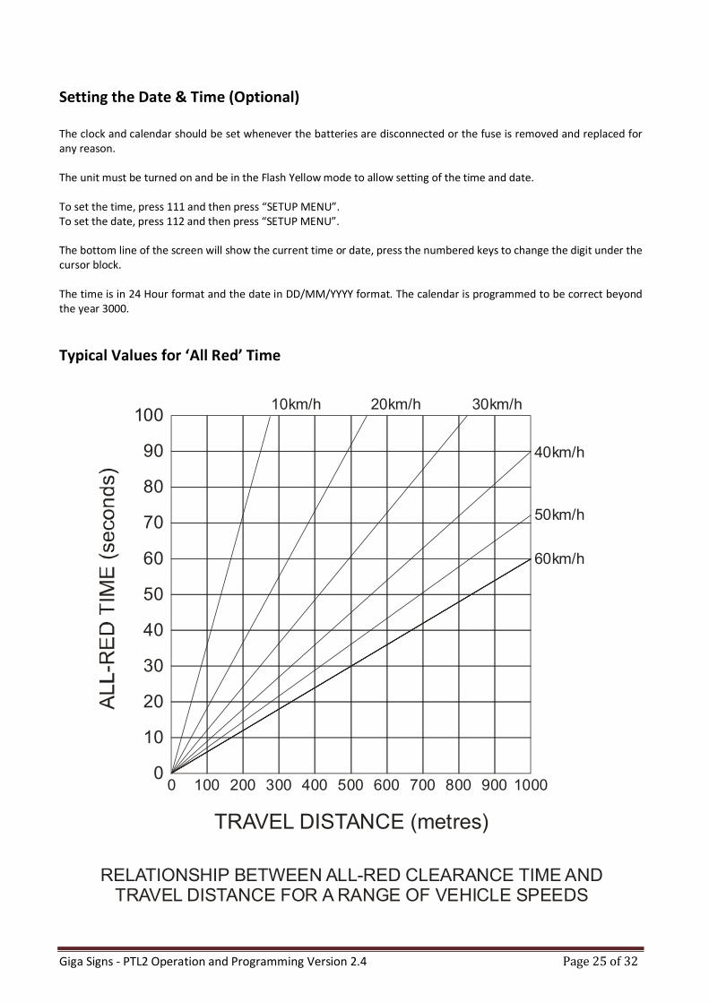
Typical Values for ‘All Red’ Time
TRAVEL DISTANCE (metres)
RELATIONSHIP BETWEEN ALL-RED CLEARANCE TIME ANDTRAVEL DISTANCE FOR A RANGE OF VEHICLE SPEEDS
100
0 100
60km/h
50km/h
40km/h
30km/h20km/h10km/h
200 300 400 500 600 700 800 900 1000
90
80
70
60
50
40
30
20
10
0
Giga Signs - PTL2 Operation and Programming Version 2.4 Page 26 of 32
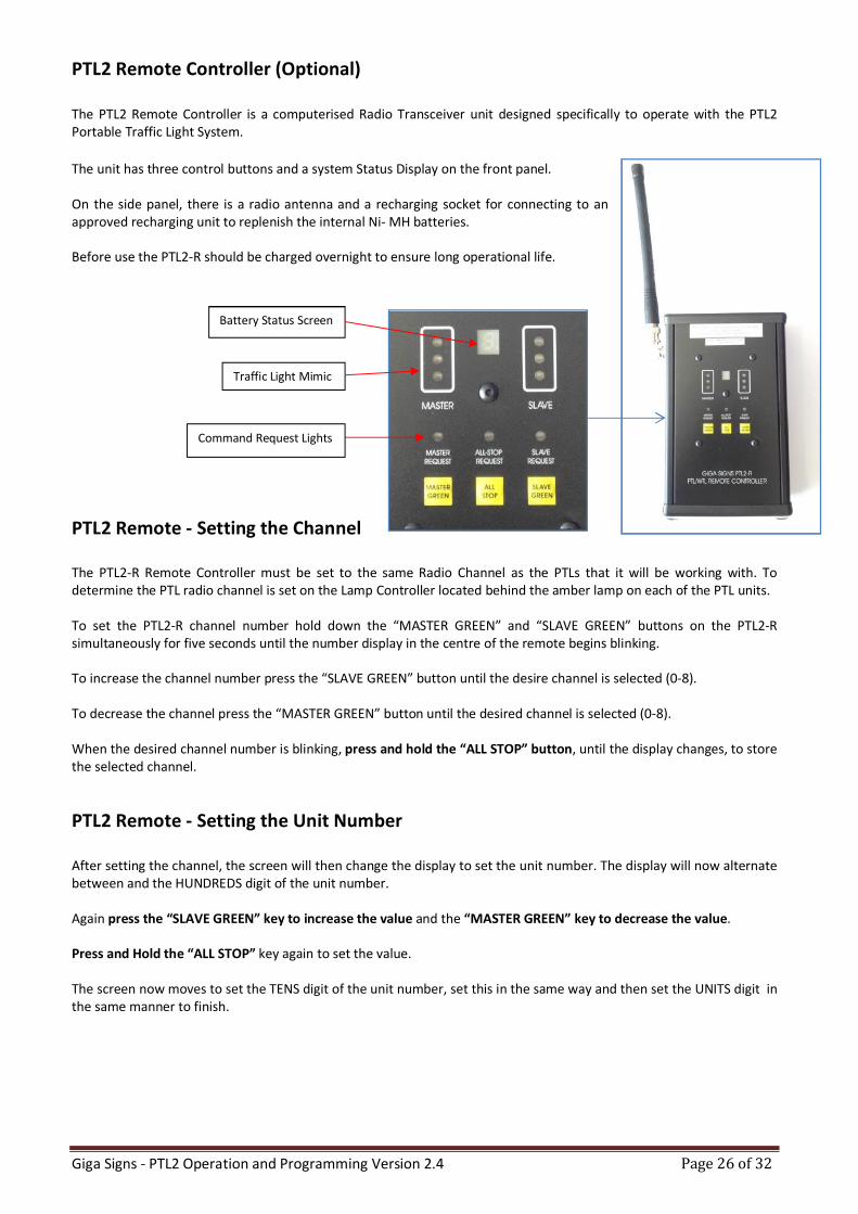
PTL2 Remote Controller (Optional)
The PTL2 Remote Controller is a computerised Radio Transceiver unit designed specifically to operate with the PTL2 Portable Traffic Light System.
The unit has three control buttons and a system Status Display on the front panel. On the side panel, there is a radio antenna and a recharging socket for connecting to an approved recharging unit to replenish the internal Ni- MH batteries. Before use the PTL2-R should be charged overnight to ensure long operational life.
PTL2 Remote - Setting the Channel The PTL2-R Remote Controller must be set to the same Radio Channel as the PTLs that it will be working with. To determine the PTL radio channel is set on the Lamp Controller located behind the amber lamp on each of the PTL units. To set the PTL2-R channel number hold down the “MASTER GREEN” and “SLAVE GREEN” buttons on the PTL2-R simultaneously for five seconds until the number display in the centre of the remote begins blinking. To increase the channel number press the “SLAVE GREEN” button until the desire channel is selected (0-8). To decrease the channel press the “MASTER GREEN” button until the desired channel is selected (0-8). When the desired channel number is blinking, press and hold the “ALL STOP” button, until the display changes, to store the selected channel.
PTL2 Remote - Setting the Unit Number
After setting the channel, the screen will then change the display to set the unit number. The display will now alternate between and the HUNDREDS digit of the unit number. Again press the “SLAVE GREEN” key to increase the value and the “MASTER GREEN” key to decrease the value. Press and Hold the “ALL STOP” key again to set the value. The screen now moves to set the TENS digit of the unit number, set this in the same way and then set the UNITS digit in the same manner to finish.
Command Request Lights
Battery Status Screen
Traffic Light Mimic
Giga Signs - PTL2 Operation and Programming Version 2.4 Page 27 of 32
PTL2 Remote - Operation
To power the unit on press any of the buttons, the unit will power off automatically after 30 seconds.
Upon power up, the three request lights will be illuminated until the remote receives communication from the system.
When communication from the system is received the display will show the status of the Master and remote aspects and any pending requests.
To use the remote, the system is normally used in the PTL Manual mode. The remote may also be used in a limited manner when the PTL is in the Vehicle Trigger mode.
The corresponding light will blink when the remote has accepted a request and will light solidly when the system has acknowledged the request, the light will extinguish when the request has been processed by the system.
PTL2 Remote Operation - Manual Mode
In Manual mode, operation of the system is controlled from the remote. In order to request a Green aspect be shown, the system must be showing RED aspects at both Master and Slave. (Ie. If either end is showing green, then the “ALL STOP” must be requested before either green can be requested). To cause the Master Unit to display a Green aspect, press and hold the “MASTER GREEN” button for 1 second. (If the remote has powered down, press any button briefly to turn it on, and then hold for 1 second). To cause the Slave Unit to display a Green aspect, press and hold the “SLAVE GREEN” button for 1 second. (If the remote has powered down, press any button briefly to turn it on, and then hold for 1 second). To cause both units to display Red aspects press and hold the “ALL STOP” button for 1 second (while the unit is on).
PTL2 Remote Operation - Vehicle Trigger Mode
In Vehicle Trigger mode, only the “MASTER GREEN” and “SLAVE GREEN” buttons may be used, when activated the function simulates a vehicle approaching the lights from the respective end. The remote can also be used when testing and setting up the Vehicle Sensors as the request from the Vehicle Sensor will be shown on the front panel indicators.
PTL2 Remote - Charging The unit can be charged when connected to either the Master or Slave trailer units, or by connecting to a vehicle 12v power outlet socket. Be sure to only use the supplied charger unit and the check that the switches are set to the 4-8 CELLS position and 1.5 AMPS position. Charging will take approximately 90 minutes from flat.
Note: It is recommended that the unit be left on charge whenever it is not in use.
Giga Signs - PTL2 Operation and Programming Version 2.4 Page 28 of 32
Troubleshooting
The fault condition will be shown on the bottom line of the Hand Controller display.
Battery Errors
If there have been a few overcast days in succession or the lights have been parked in a shaded area continuously, you can expect a low battery warning, this is normal. At the first low battery warning, it is recommended to recharge or swap the batteries over. However, if you receive a battery critical warning, it is imperative that the batteries are recharged immediately, or else you risk damaging the battery life permanently. ERRSBATLOW = Slave Battery Low ERRMBATLOW = Master Battery Low ERRSBATCRIT = Slave Battery Critical ERRMBATCRIT = Master Battery Critical ERRSBATFLAT = Slave Battery Flat ERRMBATFLAT = Master Battery Flat NB: When batteries are flat, the units will enter into Flash Yellow mode automatically.
Lamp Errors When there is a lamp error, the units will enter into Flash Yellow mode. LAMPERRSGRN = Slave Green Lamp Error LAMPERRSYEL = Slave Yellow Lamp Error LAMPERRSRED = Slave Red Lamp Error LAMPERRSAUX = Slave Auxiliary Lamp Error (at the rear of the Traffic Light head) LAMPERRMGRN = Master Green Lamp Error LAMPERRMYEL = Master Yellow Lamp Error LAMPERRMRED = Master Red Lamp Error LAMPERRMAUX = Master Auxiliary Lamp Error (at the rear of the Traffic Light head) When a lamp error occurs, open the Yellow lamp cover on the appropriate unit (Slave or Master) and press and hold the lamp test button to confirm the lamp fault. If the lamp does not illuminate, then there is a fault. In the case of a confirmed fault:
a) Open the faulty lamp cover and locate the reset push button on the driver board (on the inside of the lamp module) and press briefly whilst holding the lamp test button.
b) If the lamp does not illuminate, check the wiring from the processor unit to the lamp. c) If the fault continues, the lamp needs replacement, contact Giga Signs service stating the fault.
Giga Signs - PTL2 Operation and Programming Version 2.4 Page 29 of 32
Communication Errors
ERRCOMSLAVE = Communication between the Master and Slave units has been broken for more than 5
seconds continuously and they are now in Flash Yellow mode. The lights will try to re-establish communication for 5 minutes once a COMSLAVE error has occurred. If successful, the lights will resume normal operation. The error code will remain on the screen until the clear button is pressed, even when back to normal operation. If the lights remain in Flash Yellow mode, this means the communication between the Master and Slave units has malfunctioned. In this situation:
a) Check the Slave is turned ON b) Check the Antenna/s are intact c) Ensure the Master and Slave units are on the same frequency channel d) If a radio scanner is available, you can listen for other signals using the same radio frequency to confirm
interference. (You may not always be able to ascertain the actual interference, if in the case that it is an intermittent signal).
Diagnosing the Communication Errors
1. Look for the TX RX lights on the Master 2. Look for the RX TX lights on the Slave
If the TX is blinking on the Master, yet the RX is NOT blinking on the Slave, it indicates a likely radio transmitter fault. In this situation:
a) Open the Red Lamp on the Master to check for the light on the Maxon radio. If it is blinking red in synchronization of the TX lamp, this indicates that it is attempting to transmit.
i) If it’s not blinking red, but on steady amber, then the data cable between the Lamp Controller and the Maxon Radio is either not correctly connected or the cable or Lamp Controller are faulty. Contact Giga Signs Service stating the fault.
ii) If there is no light on the Maxon Radio, then ensure the red and black power cable between the bottom
of the Maxon Radio and the front of the Lamp Controller is connected. If the fault continues, contact Giga Signs Service stating the fault.
DOCUMENT REVISION HISTORY:
Date Document
Version Document Revision History
Document Author/Revisor
20/01/2014 V1.8 Document Revision History Added for version control.
B.B.
02/04/14 V1.9 4 Way Indepentant operation added D.E. 11/06/14 V2.0 Document Completly Re-Written D.E.
7/7/14 V2.1 Minor changes and correction of Error (MANUAL) on page 20
D.E.
18/9/14 V2.2 Safety Chain Amendment 20140723 incorperated D.E.
22/9/14 V2.3 Fault Finding Flowchart added D.E.
22/9/14 V2.4 Fault Finding Flowchart added – Giga Version Created
D.E.
Giga Signs - PTL2 Operation and Programming Version 2.4 Page 30 of 32
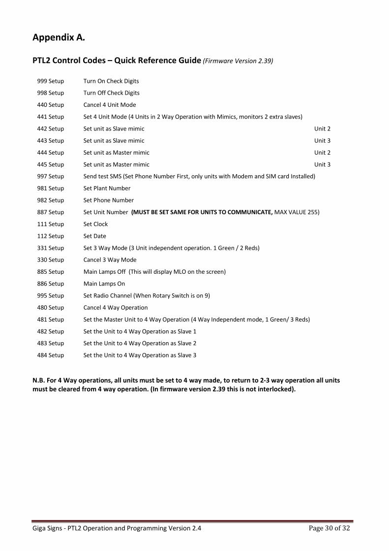
Appendix A. PTL2 Control Codes – Quick Reference Guide (Firmware Version 2.39)
999 Setup Turn On Check Digits
998 Setup Turn Off Check Digits
440 Setup Cancel 4 Unit Mode
441 Setup Set 4 Unit Mode (4 Units in 2 Way Operation with Mimics, monitors 2 extra slaves)
442 Setup Set unit as Slave mimic Unit 2
443 Setup Set unit as Slave mimic Unit 3
444 Setup Set unit as Master mimic Unit 2
445 Setup Set unit as Master mimic Unit 3
997 Setup Send test SMS (Set Phone Number First, only units with Modem and SIM card Installed)
981 Setup Set Plant Number
982 Setup Set Phone Number
887 Setup Set Unit Number (MUST BE SET SAME FOR UNITS TO COMMUNICATE, MAX VALUE 255)
111 Setup Set Clock
112 Setup Set Date
331 Setup Set 3 Way Mode (3 Unit independent operation. 1 Green / 2 Reds)
330 Setup Cancel 3 Way Mode
885 Setup Main Lamps Off (This will display MLO on the screen)
886 Setup Main Lamps On
995 Setup Set Radio Channel (When Rotary Switch is on 9)
480 Setup Cancel 4 Way Operation
481 Setup Set the Master Unit to 4 Way Operation (4 Way Independent mode, 1 Green/ 3 Reds)
482 Setup Set the Unit to 4 Way Operation as Slave 1
483 Setup Set the Unit to 4 Way Operation as Slave 2
484 Setup Set the Unit to 4 Way Operation as Slave 3
N.B. For 4 Way operations, all units must be set to 4 way made, to return to 2-3 way operation all units must be cleared from 4 way operation. (In firmware version 2.39 this is not interlocked).
Giga Signs - PTL2 Operation and Programming Version 2.4 Page 31 of 32
Yes
Yes
Yes
Yes
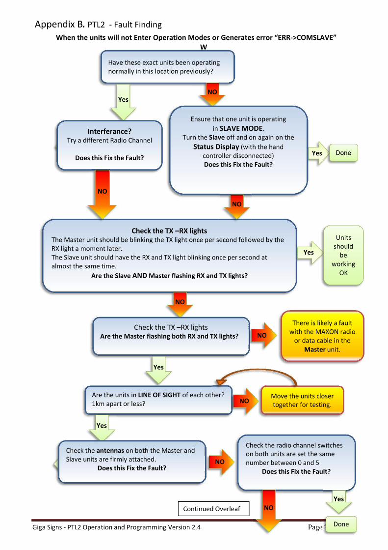
Appendix B. PTL2 - Fault Finding When the units will not Enter Operation Modes or Generates error “ERR->COMSLAVE”
W
Have these exact units been operating normally in this location previously?
Yes NO
Interferance? Try a different Radio Channel
Does this Fix the Fault?
Ensure that one unit is operating
in SLAVE MODE. Turn the Slave off and on again on the
Status Display (with the hand controller disconnected) Does this Fix the Fault?
Check the TX –RX lights The Master unit should be blinking the TX light once per second followed by the RX light a moment later. The Slave unit should have the RX and TX light blinking once per second at almost the same time.
Are the Slave AND Master flashing RX and TX lights?
NO
Units should
be working
OK
NO
NO
Check the TX –RX lights Are the Master flashing both RX and TX lights?
Yes
NO
There is likely a fault with the MAXON radio
or data cable in the Master unit.
Are the units in LINE OF SIGHT of each other? 1km apart or less?
Yes
Check the antennas on both the Master and Slave units are firmly attached.
Does this Fix the Fault?
Check the radio channel switches on both units are set the same number between 0 and 5
Does this Fix the Fault?
Yes
Done
NO
Done
Continued Overleaf
Move the units closer together for testing.
NO
NO
Giga Signs - PTL2 Operation and Programming Version 2.4 Page 32 of 32
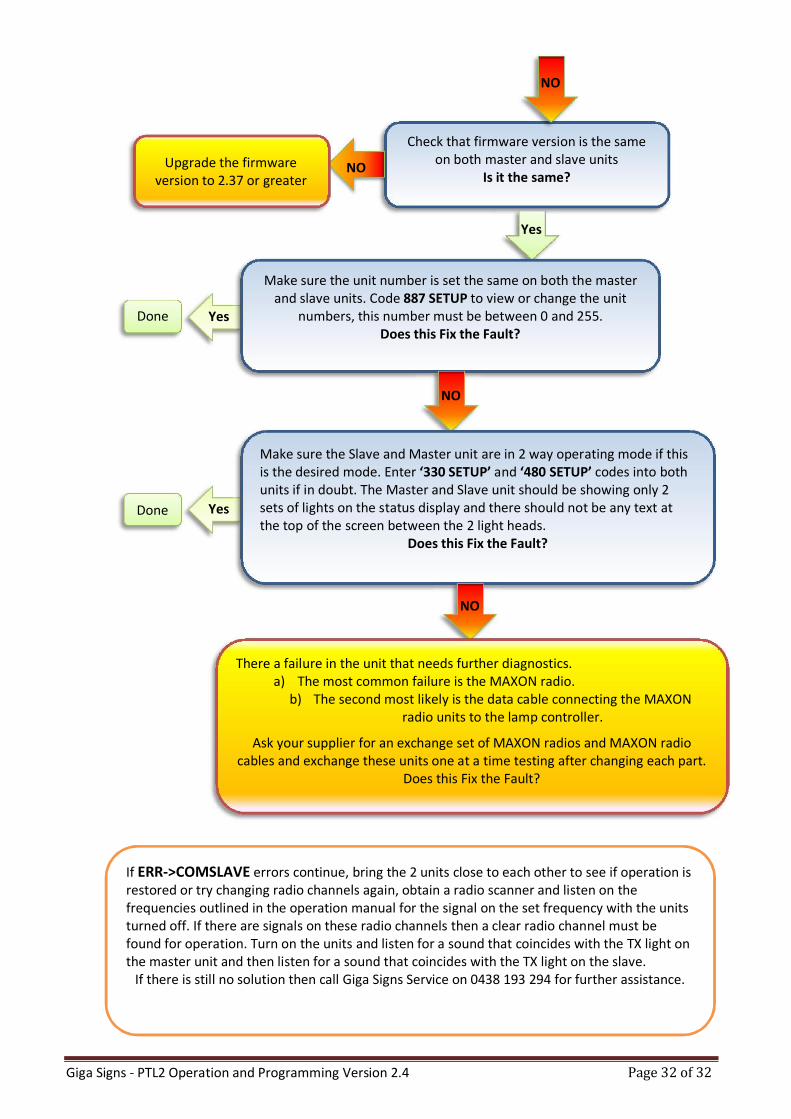
Yes
Yes
Check that firmware version is the same on both master and slave units
Is it the same?
NO
Yes
NO Upgrade the firmware version to 2.37 or greater
Make sure the unit number is set the same on both the master and slave units. Code 887 SETUP to view or change the unit
numbers, this number must be between 0 and 255. Does this Fix the Fault?
Done
NO
Make sure the Slave and Master unit are in 2 way operating mode if this is the desired mode. Enter ‘330 SETUP’ and ‘480 SETUP’ codes into both units if in doubt. The Master and Slave unit should be showing only 2 sets of lights on the status display and there should not be any text at the top of the screen between the 2 light heads.
Does this Fix the Fault?
Done
NO
There a failure in the unit that needs further diagnostics. a) The most common failure is the MAXON radio.
b) The second most likely is the data cable connecting the MAXON radio units to the lamp controller.
Ask your supplier for an exchange set of MAXON radios and MAXON radio cables and exchange these units one at a time testing after changing each part.
Does this Fix the Fault?
If ERR->COMSLAVE errors continue, bring the 2 units close to each other to see if operation is restored or try changing radio channels again, obtain a radio scanner and listen on the frequencies outlined in the operation manual for the signal on the set frequency with the units turned off. If there are signals on these radio channels then a clear radio channel must be found for operation. Turn on the units and listen for a sound that coincides with the TX light on the master unit and then listen for a sound that coincides with the TX light on the slave.
If there is still no solution then call Giga Signs Service on 0438 193 294 for further assistance.


