
Pneumatics
PROFIBUS-DP bus moduleseries BDC type V-Design


3Bosch Rexroth
Table of Contents
Notes on safety .................................................................................... 51 System architecture ................................................................. 7
1.1 Construction and design........................................................ 81.1.1 Version RMVDP/F, 1 827 030 166 ........................ 81.1.2 Version RMVDP/F_7/8", 1 827 030 205 ............. 9
1.2 Function ..................................................................................... 10
2 Presettings .................................................................................... 122.1 Baud rate ................................................................................... 122.2 Setting the bus module address .......................................... 122.3 Setting the operating modes (mode switch) ..................... 142.4 Assigning the valve supply .................................................... 162.5 Setting the bus terminator ..................................................... 17
3 Installation ..................................................................................... 183.1 Marking and identification ...................................................... 183.2 Bus module mounting ............................................................. 183.3 Electrical connections ............................................................ 19
3.3.1 Field bus connection .................................................. 193.3.2 Logic and load supply with RMVDP/F,
1 827 030 166 ............................................................ 213.3.2 Logic and load supply with RMVDP/F_7/8",
1 827 030 205 ............................................................ 234 Configuration ............................................................................... 25
4.1 Loading Device database ...................................................... 254.2 Presetting WinDP .................................................................... 264.3 Bus slave configuration .......................................................... 284.4 Valve block configuration ....................................................... 304.5 PLC address allocation .......................................................... 314.6 Loading of master parameter set ......................................... 334.7 Address assignments ............................................................. 344.8 Diagnosis with WinDP ............................................................ 37
Table of contents

4 Bosch RexrothTable of contents
5 Bus module diagnostic display ........................................... 406 Characteristics, service parts and accessories .......... 41
6.1 Characteristics ......................................................................... 416.2 Service parts and accessories ............................................. 42

5Bosch Rexroth
☞
Notes on safety
1) Order code Order numberRMVDP/F 1 827 030 166RMVDP/F_7/8" 1 827 030 205
2) In Germany, these individual licenses are issuedby the Regulating Agency for Telecommunicationsand Post (Regulierungsbehörde fürTelekommunikation und Post RegTP).
����������������� ������ ��������� ����������������������������������������� �� ��������������� ��� ������� ��������� ������ ����������������������� ���� ���� ��������������������������������������������
���������� �!"����������������#������������� ������������� ������������ ����$ %&'()��������������*+,�-.!/.�����0"�
(���������������������� �!"���������������� ��������������� ������������������ ��
������������������� ������������������� ���������������������������������������������� ���������������� ������������������������������������������������������������ �������������� ����������!"�0"
Notes on safety

6 Bosch Rexroth
1 % ��������� ������ ��������������� ���������)����� ��������)����������� �������2������������ ���� ��% ������������������� ��3��������������)����������������������� ���� ���������)����������
1 4�� ����������������������������������������������� ����� ��������������� ��������� �������������56���+�.!7.�*�%,�+,�-.!/8"6���+�.!..
1 &������� ���� ��������� ���� �����������3��������������������� ��������������� ��������������������������������
1 ��� ����������������������������� ���������� ��������������������������������������������������������� ���������
Validity These operating instructions apply to– the PROFIBUS-DP bus module (RMVDP/F and
RMVDP/F_7/8") series BDC type V-Designin conjunction with a series VTS 02, HF 03 /HF 02, MC valve block system with a multipleplug connector.
Notes on safety

7Bosch Rexroth
The versatility and flexibility of this valve block sys-tem enables Bosch Rexroth to support your automa-tion tasks. The valves are completely assembled andtested according to your requirements; the electricalconnection is made via decentralised bus modules.The valve block system in the local and external pilotcontrol versions is then ready for use. Its modularconstruction allows existing systems to be expandedor converted at any time.
The valve block system's operating instructions arecomposed of individual components.
Figure 1-1: System architecture
1 System architecture
UL/DIA
UQ1
UQ2
BF
System architecture
Valve Blocksystems with amultiple plugconnector:– series VTS 02,
HF 03 / HF 02,MC
– Bus modulesseries BDCtype V-Design:PROFIBUS-DPINTERBUS
CANopenDeviceNettype A-Design:AS Interface
– Modulesseries DDLtype V-Design:DDL / DDL-E
BDC = Bus Direct ControlDDL = Drive & Diagnostics Link

8 Bosch Rexroth
1.1 Construction and designConnections for the field bus PROFIBUS-DP, forcontrol of the valves.
1.1.1 Version RMVDP/F, 1 827 030 166Electrical connection for– valve solenoids and– logic.
– 2 rotary switches, S1 and S2, for setting the DPstation address.
– 8-position DIL switch S3 for mode settings.– 4 slide switches, S4 to S7, for assigning valves to
the supply voltage in groups (before or after theemergency off).
– 2 slide switches, S8 and S9, for terminating thebus.
BUS IN X71 andBUS OUT X72
POWER X10plug 6-pin M23
Control elements
System architecture
49.4
50(77.5)
13
2
60
UL/DIA
BF
UQ2
UQ1
015
UQ1
UQ2
PROFIBUS-DP
S3
S4-S7
S2S1
BTN
Made in Germany
PO
WE
R
X10
S8-S
9
OF
FO
N
BU
SO
UT
X72
BU
SIN
X71
53.9
Figure 1-2: PROFIBUS-DP bus module RMVDP/Fdimensioned drawing

9Bosch Rexroth System architecture
1.1.2 Version RMVDP/F_7/8",1 827 030 205
Electrical connection for– valve solenoids and– logic.
– 2 rotary switches, S1 and S2, for setting the DPstation address.
– 8-position DIL switch S3 for mode settings.– 2 slide switches, S8 and S9, for terminating the
bus.
POWER X10plug 5-pin 7/8"
Control elements
49.4
50(81)
13
2
60
UL/DIA
BF
UQ
015
PROFIBUS-DP
S3
S2S1
BTN
Made in Germany
PO
WE
R
X10
S8-S
9
OF
FO
N
BU
SO
UT
X72
BU
SIN
X71
53.9
Figure 1-3: PROFIBUS-DP bus moduleRMVDP/F_7/8" dimensioned drawing

10 Bosch Rexroth
1.2 FunctionThe bus module PROFIBUS-DP (RMVDP/F andRMVDP/F_7/8") is exclusively designed for opera-tion as a bus participant (slave) on a PROFIBUS-DPbus system according to EN 50170.
A twisted, shielded pair of wires is used as a fieldbus cable. The bus length can be up to 1.2 km(without a repeater) depending on the transfer rate.Without a repeater, 32 bus particpants (slaves) persegment are connectable. With repeaters, it isexpandable up to 127 bus partcipants (slaves).
The DP station address of the bus module is setusing the two rotary switches, S1 and S2.
The bus module automatically adjusts to the busspeed between 9.6 kBaud and 12 MBaud.
The supply voltage for logic and valve control ismonitored. If the value falls below the set threshold,an error signal is generated and the diagnosticinformation is reported via LEDs.
Station address
Baud rate
Diagnosis
System architecture

11Bosch Rexroth
#$� %�&�� $���� ����������
'#��(� &���� #�&��������'#��������"
��� ,���������������'9����������
�� ����������������*�%:���������� ����"��������������� �������������� �����������������������������������
')* &���� �����������')*����+,"
�� 9����������*!0���;�'<!�;�!8�-��"
��� ������������'<!�;�!0��
')-�*! &���� �����������')-����+,"
�� 9����������*!0���;�'<0�;�!8�-��"
��� ������������'<0�;�!0��
.� ��� .������������������������"�',5����������������#��� ��
�� &�����5��������������������������� ������� ��3������ �����
������������� ������������������������
System architecture
1) Only for RMVDP/F - 1 827 030 166

12 Bosch Rexroth
Permissible baudrates
See figure 2-1
2.1 Baud rateThe bus module automatically sets itself to the baudrate given by the busmaster. The maximum permissi-ble baud rates are:
�&��� �&��� �&���
� =�7 � �!8/�- � >
� !=�0 � -.. � 7
� =>�/- � !�-.. � !0
������������� ������������������
2.2 Setting the bus module addressAfter the PG screw cap on the bus module isopened, both rotary switches, S1 and S2, becomeaccessible for defining the station address for thevalve block system in PROFIBUS-DP. Using S1 andS2, the station address can be assigned as desiredfrom 1 to 99.
1 ���������������������������������������)��������� �����������?.?��%����������������@��:(%A���� ��������� � )��������������?.?���� �� �����3����������� ��������!07��������� ����������������� ��������������������������� ����������������������������� ��(!�� ��(0�
1 ������������� �������� ���������������� ������$ %&'()���
2 Presettings
Presettings
☞

13Bosch Rexroth
Address switch(rotary switches S1and S2)
1 ����������������������� �������������������@��:(%A���� �����������������'9����� ������
1 %������������ �����������3����������������������������� ������� ����� ���� ������
The setting of the S1 rotary switch determines thetens place (set value * 10). The setting of the S2rotary switch determines the ones place (setvalue * 1). The sum of the two settings provides thestation address.
������������ %* %-
(���� ��� �� .�����= .�����=
4��� � !. !
:������� �� .�����=. .�����=
����������������������������������������� ���
Figure 2-1: Address switches S1, S2 and modeswitch S3
Presettings

14 Bosch Rexroth
☞
See figure 2-1
%/"0 %/"1 %/"/ %/"- %/"* �����&� ���&�����
$ ������������������
$, �
$ ���9����������'<!
$, �
$ ���9����������'<0�!"
$, �
$ ���+���� �������'<!
$, �
$ ���+���� �������'<0�!"
$, �
������������������������� �������������� ��������������� �����
Presettings
2.3 Setting the operating modes(mode switch)
The S3 mode switch for setting the diagnostic mes-sages is located below the PG screw cap.
:���������������� �����$ �������� �� ��������
Switches S3.8 to S3.6 are not assigned.
1) Only for RMVDP/F - 1 827 030 166

15Bosch Rexroth
If a particular switch is ON, the diagnostic messagedescribed is sent to the bus.
Diagnostic message if a valve incorrectly shows ashort circuit. The diagnostic message is only on aslong as this valve is being triggered.
The switching voltage must be 18 V in order toguarantee safe switching! Low voltage for the valvesmeans that the UQ voltage must lie between 12 Vand 18.5 V.
If a voltage lower than 12 V occurs, this is reportedas an emergency off message.
Valve driveroverload messageSwitch S3.1
Low voltagemessage 1)Switch S3.2 UQ1Switch S3.3 UQ2 2)
Emergency offmessageSwitch S3.4 UQ1Switch S3.5 UQ2 2)
Presettings
1) After approx. 10 ms when turning on.After approx. 20 ms when turning off.
2) Only for RMVDP/F - 1 827 030 166

16 Bosch Rexroth
2.4 Assigning the valve supplySwitches S4-S7 for assigning the valve supply arelocated below the PG screw cap. 4 valve positions(each with solenoids 12 and 14) are assigned toeach switch.
Each valve group can be assigned one of the twosupply voltages, UQ1 and UQ2, via the position of theswitches S4-S7.
If, for example, the supply voltage UQ1 is fed throughthe emergency off and UQ2 is not, the valves that aresupplied by UQ2 remain functioning in case of anemergency off.
:���������������� �����'<!�������� �� �������3��� � ���������������������� ���������� �������������������'<!�
%�������%1�%2� ��������������������������������3
Valve positions1-4 5-8 9-12 13-16
Example
☞
Figure 2-2: Switches S4-S7
Assigning switchpositions to thesupply voltages UQ1and UQ2
Assigning switchesto valve groups
Presettings
Only for RMVDP/F1 827 030 166

17Bosch Rexroth
2.5 Setting the bus terminatorIn order to minimise wire reflection and ensure adefined idle level in the PROFIBUS-DP transmissionline, the transmission line must be equipped with abus terminator at both ends.The bus terminator is integrated in the equipment forbus module RMVDP/F. Switches S8-S9 are locatedbelow the PG screw cap.
&����������������� �����$ �������� �� ������3���� � ������������������� ������� �����������
If the bus module is attached at the end of the trans-mission line, the bus terminator must be activated.
%������������� .������ ������
(8 (=
$ $ ����������
$, $ ,����������
$ $, ,����������
$, $, :�������
��������!������� ������"�����������#��$
☞
Figure 2-3: Switches S8-S9
Bus terminator,switch positionsS8-S9
Switches S8-S9
Presettings

18 Bosch Rexroth
3 Installation
✍3.1 Marking and identificationThe address provided/used for the bus module isinscribed on the bus module in the bus participant's(slave) field.
3.2 Bus module mountingThe bus module is placed on the multiple plug con-nector of the valve block system and screwed tight.
A�������������������� ����������� ������ ���������������������� ������������������ �
Figure 3-1: Bus module mounting on the valveblock system's multiple plug connector
Gasket
☞
Installation
1 ����������������������� ���������������*������� ������ ������ �������������������������"���� ��������������������������B
1 $ ������������������������� ��� ���3�����%��7-������� ������������������� ������� ��������+,�7.-0=�

19Bosch Rexroth
3.3 Electrical connections3.3.1 Field bus connection– The BUS INX71 plug for connecting the incoming
field bus cable and– the BUS OUTX72 socket for connecting the out-
going field bus cableare located on the RMVDP/F bus module.
If it is the last station in the field bus connection, theremote bus is only connected to BUS IN X71 andclosed via switches S8-S9 using the bus terminatorsupplied internally. A PG protective cap is put on theBUS OUTX72 socket.
Figure 3-2: Two-way field busconnection
Figure 3-3: Field busconnection as the laststation
BUS INX71
BUS INX71
BUS OUTX72
PGprotectivecap
See table 3-1BUS IN X71 andBUS OUT X72assignment
See section 2.5Bus terminator
Installation
20 Bosch Rexroth
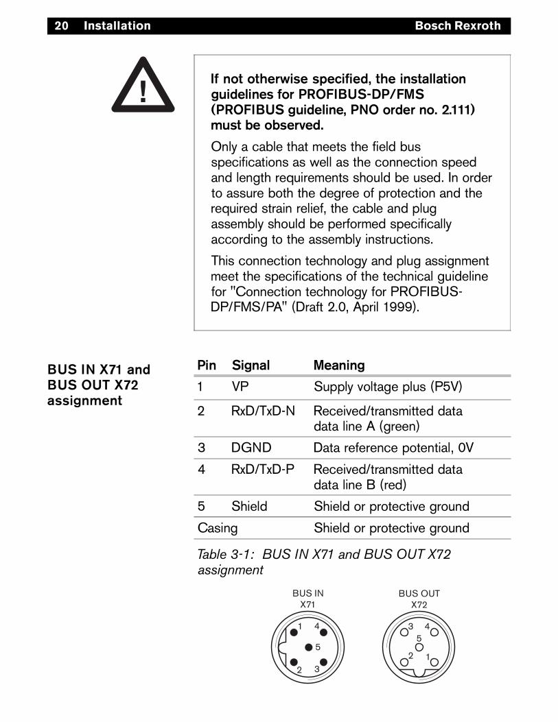
(������������������������ ���������������&���������������+�(.'%������%���+�(.'%�&������� ��4+���������"�-"***! ���������������"
$ ����������������������������������������������� ������������������� ����� ������� ���� �����2����� �������������������% ��������������������������������������� �� ������2��������� ������3������������ ��������������������������������������������������� ������������������� ������� ��
������� ����� ����� ������� ������������ �� ���������������������� ������������� ������������ ����?A� ����� ����� �����������$ %&'()��� �(��:?�*�����0�.3�:����!==="�
��� %�&�� ������&
! �� (������������������*�-�"
0 �#���#�), ���������� ������������������� ��:�*��� "
> �4,� ��������� ������� ����3�.�
C �#���#�)� ���������� ������������������� ��&�*��"
- (����� (�������������������� �
A��� � (�������������������� �
�����������%��&'�()������%��*%��()������� ���
BUS IN X71 andBUS OUT X72assignment
Installation

21Bosch Rexroth
3.3.2 Logic and load supply with RMVDP/F,1 827 030 166
The valves and the bus module are all powered viathe plug POWER X10.
The bus module operating voltages must be con-nected via the coupling socket (accessories) inaccordance with Table 3-2.
The operating voltages given in the electrical datacharacteristics must be adhered to.
����0C)����������� ��������� ������������� �������������� ���
5���������������� ������� ���� ������������������������������������������������&�����(4�$4�6721- ��������������$�700*"
��� �+8$��9*7 ����&� ���
! �+ ������������ �*������ ���� ����"
0 '<! �����������������3�����
> .�'< 4�� �����'<!
C '9 (������������&���������������
- .�'9 4�� �����'9
7 '<0 (��� ���������������3������
�����������*+,-�(�.������������ �������������� ������-�/0�12
���������'<�� ��'9�������� ����������������������������������� ��������� �������������� ������������
POWER X10
See section 6.2
See section 6.1
POWER X10 plugpin assignments(bus moduleRMVDP/F)
Installation

22 Bosch Rexroth
The following current levels must be provided. Thecable cross-sections must be selected according tothe cable length and the operating current:
%�&�� ����&� ��� 5����������
'9 9���� ��#��.�0�:
'<! ����� ��#��0�0-�:
'<0 ����� ��#��0�0-�:
��������������������� ������������
POWER X10 powerconsumption(bus moduleRMVDP/F)
Figure 3-4: POWER X10 on the bus moduleRMVDP/F
Installation

23Bosch Rexroth
3.3.2 Logic and load supply withRMVDP/F_7/8", 1 827 030 205
The valves and the bus module are all powered viathe plug POWER X10.
The bus module operating voltages must be con-nected via the coupling socket (accessories) inaccordance with Table 3-4.
The operating voltages given in the electrical datacharacteristics must be adhered to.
����0C)����������� ��������� ������������� �������������� ���
5���������������� ������� ���� ������������������������������������������������&�����(4�$4�6721- ��������������$�700*"
��� �+8$��9*7 ����&� ���
! .�'< 4�� �����'<
0 .�'9 4�� �����'9
> �+ ������������ �*������ ���� ����"
C '9 (������������&���������������
- '< (������������3�����
��������!��*+,-�(�.������������ �������������� ������-�/0�123)1#4
���������'<�� ��'9�������� ����������������������������������� ��������� �������������� ������������
POWER X10
See section 6.2
See section 6.1
POWER X10 plugpin assignments(bus moduleRMVDP/F_7/8")
Installation

24 Bosch Rexroth
The following current levels must be provided. Thecable cross-sections must be selected according tothe cable length and the operating current:
%�&�� ����&� ��� 5����������
'9 9���� ��#��.�0�:
'< ����� ��#��0�0-�:
��������5������������ ������������
POWER X10 powerconsumption(bus moduleRMVDP/F_7/8")
Figure 3-5: POWER X10 on the bus moduleRMVDP/F_7/8"
Installation
PO
WE
RX
10
AC
UQUL
0VUQ0VULAC
24 V
24 VPE
123
54

25Bosch Rexroth
4 Configuration
������������� �� ������������ ��������������������D� ��3������ �!�=C3�� � ��� ��D� �����=-3�=8�� ��,��&��������� ���!�./.�.//�=C-�
4.1 Loading Device databaseThe Device database includes the performancecharacteristics of the DP slave or DP master. TheDevice database is standardised in accordance withEN 50170, part 2, PROFIBUS. In this way, DPcomponents from different vendors can be imple-mented with one planning software package.
Each valve block system is equipped with valves asordered and it must now be configured as a DPslave using the WinDP programme (Bosch).
To plan with the valve block system using BoschWinDP the Device database files must be copied tothe subdirectory GSD, ex.:\Device database (GSD)\PROFIBUS\DP\GSD.For more details, see the "README" file on theDevice database diskette.
The diskette with the Device database or type files,Bosch order no. 1 070 075 547, includes all moduledata for the valve block systems.
☞
Configuration

26 Bosch Rexroth
Figure 4-1: WinDP Presets menu
Configuration
4.2 Presetting WinDPThe WinDP utility programme runs on top ofWinSPS. Only existing PLC projects can be workedon with the WinDP software. Therefore, after startup, WinDP searches for the directory where the PLCproject is located. The project name found there isthen put into the "Presets" field. The directory thatthe Device database was copied to must also beidentified (see section 4.1).

27Bosch Rexroth
Figure 4-2: Busmaster selection menu
Configuration
After confirming with OK, you must select thebusmaster built into your control in the "Busmasterselection" window. You then enter the WinDP editor,where you configure the PROFIBUS-DP. In the workspace of the editor, the first hierarchical level con-tains the busmaster you specified, assigned to busaddress 1.

28 Bosch Rexroth
4.3 Bus slave configurationIn the bus slave window all slaves are displayedwhose Device database files lie in the directory thatwas entered into the "Device database path" in thesection "WinDP Presets" (see 4.2). In order toconfigure the valve block system as a slave in thePROFIBUS-DP, select the valve block system busmodule in the "Bus slave" window.
The bus module is designated as “RMVDP/F”. 1)
Click on the bus slave “RMVDP/F”, and hold downthe left mouse button dragging the bus slave towardthe left to the busmaster and into the work area. Assoon as a square with a + appears under the mousepointer, release the left mouse button and the busslave is then dropped. WinDP draws the bus linefrom the master to the new bus slave “RMVDP/F”and assigns it to the next available bus address.
If the bus address does not agree with the addresson the bus module (the address assigned in section2.2), the address field in the work area can beopened by double clicking and the addresses canbe corrected there.
See figure 4-3
Configuration
1) For RMVDP/F and RMVDP/F_7/8"
29Bosch Rexroth
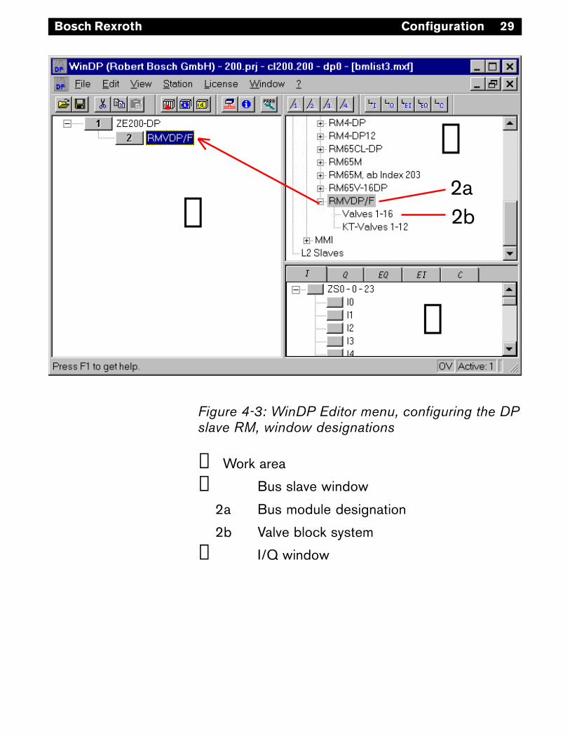
Figure 4-3: WinDP Editor menu, configuring the DPslave RM, window designations
➀ Work area
➁ Bus slave window
2a Bus module designation
2b Valve block system
➂ I/Q window
Configuration
➀
➁
➂
2b2a

30 Bosch Rexroth
4.4 Valve block configurationBecause the valve block system is a modularly con-structed slave, the valve block must now be addedto the bus module. By double clicking on the"RMVDP/F" bus slave in the bus slave window, allavailable modules for this bus slave are displayed.By clicking and then dragging, set the valve block"valves 1-16" on the bus module in the workingwindow.
$ ���������#����� ��������������������������� ��*�� ����� �������"�� ��������������������������� ����������������� ����������������� ���������������� ������ ����� �B
���������������������������������������� ������.�
A� �������� �������������� �� ������������ �� ���������������� ��������������
In order to activate the valves, you must assign PLCoutputs to the output bytes. WinDP automaticallyshows the number of bytes that will be transferredon the PROFIBUS-DP. There are always 4 outputbytes with HF valves. The byte transfer on thePROFIBUS-DP does not depend on whether thesebytes are allocated to PLC outputs.
☞
Configuration

31Bosch Rexroth
4.5 PLC address allocationAll– Inputs (I),– Outputs (Q),– Extended Inputs (EI) and– Extended Outputs (EQ),as well as special channels are listed in the I/Qwindow of WinDP. The selection of the PLC addressspace was taken into account in the presettingstage. If symbol files are defined there, the symbolsand symbol comments of all inputs and outputs aredisplayed.
Select field Q for outputs and then a free PLC out-put and click on it in the I/Q window. By holdingdown the left mouse button, the output can bedragged and dropped on a valve block output bytein the work space.
In the example, the PLC output Q0 was allocated tothe first output byte of the valve block system, Q1 tothe second, etc.
See figure 4-4
Configuration

32 Bosch Rexroth
Figure 4-4: WinDP Editor menu, assigning PLCaddresses
After the drop, WinDP assigns the address of thebus slave to the PLC output in the I/Q window. Youcan immediately see which PLC addresses are stillavailable.
%������� ��)��������������������������� �����������3������������������������ ������ ������3�� ���������� ���������9A����������� ������������
D�������� ��������9A������������������������������ ����� ��������������B
☞
Configuration

33Bosch Rexroth
4.6 Loading of master parameter setBefore you make a connection to the busmaster, youmust check and, if required, adjust the busmasterDIP switch positions. The busmaster coupling fieldis set by the DIP switch S4.
After all PROFIBUS-DP slaves are configured, theinformation in the busmaster file must be transferredtogether with the bus parameters set in WinDP(baud rate, etc.) to the busmaster. To do this, selectthe menu item "File, Load". WinDP prepares themaster parameter set MPS, containing all dataneeded for operation of the busmaster, slave andbus system PROFIBUS-DP and then transfers thisinformation to the busmaster.
Only forBM DESI-DP12See section 2.2.2
See figure 4-5
Figure 4-5: WinDP Editor menu,Loading of master parameter set
The busmaster is stopped during the loading proc-ess. A dialogue window appears with a prompt.Select "Yes" to execute the loading process. Afterthe loading process is complete, the busmaster isrestarted, again based on a prompt.
After the MPS is read, all of the PLC input andoutput adresses of the slaves are recognised by thebusmaster.
Configuration

34 Bosch Rexroth
Now the UL/DIA LED on the valve block system'sbus module must illuminate continuously and the BFLED should be off. The status display on thebusmaster must extinguish (see the busmasterhandbook).
4.7 Address assignmentsTo be able to activate specific valves, it is necessaryto allocate the bits of a PLC output to the individualvalve positions on the valve block.
If you have allocated a 12-position valve block toPLC addresses Q0 to Q2, the individual bits ofthese 3 bytes should be set up according totables 4-1a and 4-1b.
������������������������������8������������ ��������� ���0��������������3�<.�� ��<!�
Connection 0 corresponds to bit 0.
Valve block addressassignment
Also see table 4-1aand table 4-1b
☞
Configuration

35Bosch Rexroth
������������
%�������#$�
.��� �������
! !C . <.�.
!0 <.�!
0 !C <.�0
!0 <.�>
> !C <.�C
!0 <.�-
C !C <.�7
!0 <.�/
- !C ! <!�.
!0 <!�!
7 !C <!�0
!0 <!�>
/ !C <!�C
!0 <!�-
8 !C <!�7
!0 <!�/
������!������������������ ���������6��6������7� ��6��6��������������#
Addressassignment on thevalve block, valvepositions 1-8
☞ A�� ��)��������� ����������� ����!C�
Configuration

36 Bosch Rexroth
������������
%�������#$�
.��� �������
= !C 0 <0�.
!0 <0�!
!. !C <0�0
!0 <0�>
!! !C <0�C
!0 <0�-
!0 !C <0�7
!0 <0�/
!> !C > <>�.
!0 <>�!
!C !C <>�0
!0 <>�>
!- !C <>�C
!0 <>�-
!7 !C <>�7
!0 <>�/
������!������������������ ���������6��6������7� ��6��6������������$��8
Addressassignment on thevalve block, valvepositions 9-16
☞ A�� ��)��������� ����������� ����!C�
Configuration

37Bosch Rexroth
4.8 Diagnosis with WinDPDiagnosis with WinDP and the diagnostic display onthe bus module can provide information on errors ifthe LEDs UL/DIA on the bus module do not illumi-nate continuously or one of the UQ1 or UQ2 LEDs islit or if there is a message on the status display ofthe busmaster.
To use the diagnosis in WinDP click on the menuoption "View, Diagnostic". Detailed error and diag-nostic messages from the busmaster and slaves arelogged in the diagnosis output.
Here the PROFIBUS-DP along with the programmer(address 0), the busmaster (address 1) and thefields for the slaves (bus slaves with addresses 2 to125) are displayed in the upper half of the window.
In the example in figure 4-6, the slave at address 2reports an error and address field 2 has a red back-ground. If the bus slave is clicked on, the corre-sponding diagnostic message is received in the textwindow: "Bus station can not be reached."
In the example in figure 4-7, the slave at address 2reports an error and address field 2 has a yellowbackground. The message shows an equipment-related diagnosis: "Low voltage UQ1" and "UQ2 notexisting".
See section 5Diagnostic display
See figure 4-6
See figure 4-7
Configuration

38 Bosch Rexroth
Figure 4-7: Diagnostic window with voltage error
Figure 4-6: Diagnostic window with configurationerror
Configuration

39Bosch Rexroth
Figure 4-8: Module data window
After the error has been corrected and after thecorrect master parameter set is loaded into thebusmaster, the diagnosis should display an error-free PROFIBUS-DP.
If you click a module using the right mouse button inthe bus slave window in WinDP, the Module datawindow opens and the module's configuration datais displayed.
Module data
Configuration

40 Bosch Rexroth
#$� %�&�� $���� ����������
'#��(� &���� '#��&���������������"
��� ,��'9������������������ ��
�� ����������������*�%:���������� ����"��������������� �������������� �����������������������������������
')* &���� ')*���������������+,"
�� 9����������*!0���;�'<!�;�!8�-��"
��� '<!������������;�!0��
')-�*! &���� ')-���������������+,"
�� 9����������*!0���;�'<0�;�!8�-��"
��� '<0������������;�!0��
.� ��� .������������������������"�',5����������������#��� ���
�� &�����5��������������������������� ������� ��3������ �����
������5������ ������������������������
The LEDs on the front panel of the bus module showthe messages of the following table.The diagnostic display works independently of themode switch's settings in section 2.3.
5 Bus module diagnostic display
Bus module diagnostic display
1) Only for RMVDP/F - 1 827 030 166

41Bosch Rexroth
:�����
% ��������� �������� : �
����������������� +,�7.-0=�%+A�7.-0=
%��7-���� ����������
:���� ����������� ϑ' E-�FA����E-.�FA
$�����
������������������� ' 0C����A�*6!-�G���E0.�G"
������������������� ' 0C����A�*6!-�G���E0.�G"
$���� �&������ ���������
% ����� ������� ��� +,�7!!>!)0H�!==C
% ����� ������ �� +,�-..8!)0H�!==>
6 Characteristics, service parts andaccessories
6.1 Characteristics
Characteristics, service parts and accessories

42 Bosch Rexroth
$������� $��� ����
&��������������$ %&'()���I
������� *�;-2�7/7�*66
�������<2�;= *�;-2�7/7�-70
I��������� ������������ � ��������� ��������
��������� $��� ����
������� ����� ����������������37)�� ������������������
�0>3�(��������� ������� ����� *�;-1�1;1�70/
�0>3�(�������� ������� ����� *�;-1�1;1�7/7
������� ����� ����������������3-)�� ������������������<2�;=
/�8?3�(�������� ������� ����� (�������!"
/�8?3�(�������� ������� ����� (�������0"
������� ����� ���������� ����� 3�-)�� �����3��������� ������� �����
*�;-1�1;1�7-6
������� ����� ���������� ����� 3�-)�� �������3��������� ������� �����
*�;-1�1;1�7-2
�!0������������� *�;-/�/*-�77*
��������������3�4(����������3�>�!�0? *�727�720�012
&��������3������3���A&��������3������3������ �������������� ������ �������3��'�3��� ����������!..�,����� �������3��'�3��� ����������0.�,3����� �������������� �
*�727�>*2�-7-*�727�>*>�66**�727�>*2�-7**�727�>*>�667
�
������� A�������� $��� ����
!" � J�&� ���4��K�L�A���M����������0/�)/C!/0�,��������
7)8��� (������������� >-�-111�*-�70
!.)!0��� (������������� >>�-111�/-�70
7)8��� (������� ���� >>�-111�0-�70
0" �������� ���4��K���������!!�7-�)/!-/.�$��� �����
7)=3-��� (������������� 77�7-2�66*
6.2 Service parts and accessories
Characteristics, service parts and accessories


1 987 765 434 (03.02) en • Subject to technical modification
Your concessionary
Bosch Rexroth AGPneumaticsBartweg 13D-30453 HannoverTel.: 05 11 / 21 36 - 0Fax.: 05 11 / 21 36 - 2 69E-Mail:[email protected]/pneumatics
BR
P/V
MK
2(S
i) •
Prin
ted
in G
erm
any
USBosch Rexroth CorporationPneumaticsP.O. Box 135971953 Mercer RoadLexington, KY 40511-1021Phone: 859-254-8031Fax: 859-254-4188


