
Automotive Electrical and Electromechanical System Design
Dr.-Ing. Uwe KnorrProduct Marketing Director
Ansoft CorporationPittsburgh, PA

Challenge #1:Multi-Domain Design
Mechanical
Electro-Chemical
Hydraulic
Electrical
Controls
Magnetic
Pneumatic
Thermal

Multi-Domain Design
Multiple Domains are interconnected and influence each otherThe electrical content of vehicles increasesMore and more controls are involvedElectrical systems closely interact with other domains
Electro-ChemicalElectro-MechanicalElectro-MagneticElectro-Thermal

Challenge #2: Multi-Level Design
Accuracy
Com
plex
ityD
etails
# of
Com
pone
nts
)()()(
)()(
)()()(
)()(
11
111
11
111
ttpdttd
Rtitv
ttpdttdRtitv
dq
qd
dd
ψωψ
ψωψ
⋅⋅++⋅=
⋅⋅−+⋅=
EQU
X Y
NL
XY1
NL1
I_main
sp
vset
vbus
vbus := VM1.V
D1
CONST
CONST GAIN
I LIMIT
VBUS
VSET
ERR
GAIN1
INTG1 SUM1 LIMIT1
+ V
VM1
I1
GAIN
GAIN2
engine2generator
INREG
OUTREG
GAIN
GAIN3
GAIN
GAIN4
VBUS<VSET
VBUS>=VSET

Multi-Level Design
Different analyses require different model accuracy levelsDifferent analyses require different algorithmsDifferent accuracy levels require different modeling languagesModel exchange from one level to the next higher level requires model extractionDesign information must be exchanged between different design groups

Challenge #3:Multi-Organizational Design
Tier IIComponent
Tier ISubsystem
OEMSystem

Multi-Organizational Design
Geometry, Material, Structure
Fundamental Physics, DC, AC, TR, FEA, Stress
TIER II
Circuits, Block Diagrams, State Machines, C-Code, Lookup Tables
Controls, Circuit Design, Statistical, Optimization, AC, Short Transients
TIER I
System Models with lookup tables minimum parameters
Statistical, Worst Case, Drive Cycle, FMEA, Long Transients
OEM
ModelAnalysis

Design Challenges Today
Control
Electrical
Mechanical
Component Supplier
System Integrator
Tier 1 Supplier
Circuit
System
Component
Hydraulics
Tier 2 Supplier
Thermal
Magnetic
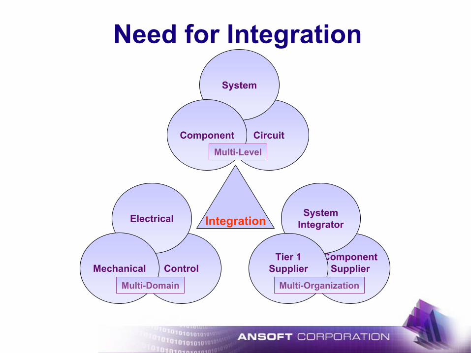
Need for Integration
Integration
Control
Electrical
MechanicalComponent
Supplier
System Integrator
Tier 1 Supplier
Circuit
System
Component
Multi-Domain
Multi-Level
Multi-Organization

EM Design EnvironmentSIMPLORER Simulation Data Bus
Simulator Coupling Technology
CircuitSimulator
Block DiagramSimulator
State MachineSimulator
Simulink
MathCad
Maxwell2D/3DElectromagnetismElectro mechanics
C/C++ Interface
Model DatabaseElectrical, Blocks, States, Machines, Automotive, Hydraulic,
Mechanics, Power, Semiconductors…
VHDL-AMSSimulator

Integrated Design Environment
WIN/2000WIN/XPWIN/NT
Pentium>256MB

CompatibilityMS-Office compatible
Read and write Excel, AccessCopy & Paste to and from Word, PowerPoint, Excel…Windows Printing Support
Data Format compatibleASCIIAccess (*.mdb)Excel (*.xls)CSV (*.csv)Comtrade (*.cfg)SPICE (*.out)TEK – Oscilloscope data (*.dat)
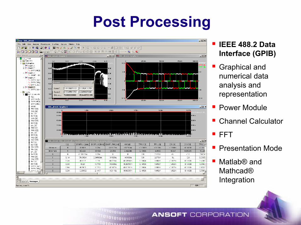
Post ProcessingIEEE 488.2 Data Interface (GPIB)
Graphical and numerical data analysis and representation
Power Module
Channel Calculator
FFT
Presentation Mode
Matlab® and Mathcad® Integration

Component Characterization
2D, 3D, multi dimensional lookup table
# L1
# C1
NL
NL_Charact
YZ
X
V3DLUT
E1 Y t
V_LUT
M3 ~BA
C
IM1
Y tM_LUT1
• Characteristics
• Stimuli
• Loads
Data Acquisition
Data Transfer
Data Processing

State Machines
Behavioral Modeling
Smart models, state dependent step size
modification
Event driven modification of topologies & parameters
Online measurement of characteristic
values

Relay Model
com
no
drvm
drvp Relay
E1 R1E2
S1
LCoil := 250m
RSup := 680
ROn := 5mtdbrk := 8m
tdmk := 12m
VPULL := 7
VDROP := 2
RCoil := 3CCoil := 40n
E5
S3
E6
R3
Relay.IinRelay.Iout
t
14.00
-2.00
2.004.006.008.00
10.00
0 0.600.20 0.40
R1pNoRs1
Final Relay Model
Relay Macro
Symbol Editor

Relay Model
Rsup
LCoil
RCoil
ROn
S1
drvp
drvm
no
com
ON_DIS
DELAY_OFF_ON
DELAY_ON_OFFLCoil.I >= IPULL
LCoil.I <= IDROP
lon
loffOFF_DIS
DEL: loff##tdbrk
DEL: lon##tdmk
EQU
IPULL := VPULL/RCoil.RIDROP := VDROP/RCoil.R
A+ AM1
+ V
VM1
CCoil
• Fast!
• Easy model generation
• Good numerical behavior

Block Diagrams Analog and Digital Controller Modeling
CONTR_OUT
op2 := 2.5
ymax2 := 1
op1 := -2.5
ymax1 := -1
-16.66m
N"GSMP_1" LIMITER
u_limit := 20l_limit := 0
EXT
P_GAIN
KP := 50I_GAIN
KI := 20
P
I
LIMIT
EXT
CONST
NSET
16.666667
Each block can be
assigned an individual
sampling time or run with
system time step
PI
C/C++Code
NL

DC Motor Drive System
L_R
L_S
L_T
ET1
ET2
ET3
CD1m
R_R
R_S
R_T
Yt
LOAD
CONTR_OUT
THRES2 := 2.5
VAL2 := 1
THRES1 := -2.5
VAL1 := -1
-16.66m
DCM.N P_GAIN
KP := 50I_GAIN
KI := 20
LIMITER
UL := 20LL := 0
10m
GAIN GAIN
I
LIMIT
CONST
N_REF
16.6667
0.3m
M
DCMRA := 1.2
LA := 9.5mKE := 0.544
J := 4m
A+ AM1D1 D2 D3
D4 D5 D6
D7
TR
CONST
CLOCK
.1m
Wiper System

Wiper System – Result
Motor Torque and Load Torque
Motor Speed
N_REFN
T
20.00
-10.00 -10.00
0 0
0
0
100.00m
100.00m
50.00m
50.00mT
15.00
00
10.00 10.00
0
0
100.00m
100.00m
50.00m
50.00m

Automotive Library
Power Storages
Wires
Battery - Basic Model
Battery
Fuel Cell
Wire - Thermal static
Wire - Thermal dynamic
Wire - Thermal dynamic II
Wire with Thermal Pin
Wire - Advanced
Wire - Advanced II
Gauge based
Fuses
Wire - Thermal static
Wire - Thermal dynamic
Wire - Thermal dynamic II
Wire with Thermal Pin
Wire - Advanced
Wire - Advanced II
Fuse - Single Element
Fuse - Double Element
Fuse - Advanced
PPTC (Three RC combinations)
PPTC (Two RC Combinations)
Lamps
Lamp - Filament
Lamp - Single Filament
Lamp - Double Filament
Lamp - Advanced
Relays
Relay - Normally Open
Relay - Normally Closed
Relay - One Pole, Two Throws
Relay - Two Poles, Two Throws
Relay - Two Poles, Cross-Strap
Spark Plugs
Spark Plug
Machines
Alternator - Transient Model
Alternator - Average Model
Alternator - Current Source
Starter
DC Machine
Mechanical Models
Inertia
Friction
Fan
Ideal Gearbox
Gearbox with Losses
PWM Models
PWM
PWM Switch
PWM Load
Flasher Switch
Connectors
Inline Terminal Pair
Eyelet Terminal
Engine Models
Engine - Speed Source
Engine - Dynamic Model
Applications:• Electrical Distribution
System of Vehicles• Power Management• Drive Cycle Analysis• FMEA• Statistical Analyses
Industries:• Automotive
Manufacturer• EV/EHV• Aerospace• Defense• Ship Building Industry
Automotive System Library

Automotive Library
Yt
Y t
Battery- +
Engine Block Ground
ChassisGround
To Hazzard Flasher
To Head Lamp Switch Lamp Switch
battery1
fuse1_5Amp
fuse2_15Amp
rlyno1
S1
TS1_HIGH_LOW_Beams_Switch
Low
High
Low High
High
Low
RH HeadLamp
LH HeadLamp
TailLamps
Turn Signal
Y t
Y t
QuickGraph1
N0161.V
t
14.00
-2.002.00
6.00
10.00
0 60.0020.00 40.00
S2
S3
D1 D2
t
60s
itp11
itp19
Probe1
t
7.50
-2.50
0
5.00
0 60.0025.00 50.00
Exterior Lighting System
Inrush Currents
Turn Signal Voltages

Automotive Library
BenefitsEasy to use and intuitive graphical modeling Easy parameterization using Wizard technologyStatistical analyses, optimization and parameter variationsCharacterization tool for fusesMultiple model levels for components Web based example database with jump start projects Animated symbols for easy visual inspection

Electro-Chemical Components
Lead Acid BatteryFuel Cell
FuelCell
+-
Battery- +

EV/EHV – Charging System
ST_r1
L1
00.1m
RLoad
RLTR1
D1
ICA:
L1.I>=I_command
ST_r1.VAL>=0.99 and L1.I<I_command
On
SET: cs:=1
Off
SET: cs:=0
period := 20u
Off2
SET: RL:=10
t>3m t>12m
SET: RL:=5 SET: RL:=5
t>0.0025
SET: I_command:=10 SET: I_command:=15
VM1.V
t
6.10
5.10
5.20
5.30
5.40
5.50
5.60
5.70
5.80
5.90
6.00
0 20.00m2.50m 5.00m 7.50m 10.00m 12.50m 15.00m
+ V
VM1
L1.I
t
16.00
0
2.00
4.00
6.00
8.00
10.00
12.00
14.00
0 20.00m2.50m 5.00m 7.50m 10.00m 12.50m 15.00m
t0 20.00m2.50m 5.00m 7.50m 10.00m 12.50m 15.00m
Output Voltage
Input Voltage
Inductor Current
TransistorControl modeledusing statemachines
Load resistanceand referencecurrentmodificationmodeled usingstate machines
BoostConverter
FuelCell
+ -
FUELCELL_A2
Battery-+
LBATT_A2

Multi-Domain Design
• Hydraulics
• VHDL-AMS
• Mechanics
• Electro Mechanical
• Magnetics
• …

Hydraulic Library1 0
3
r1
pk_150

Hydraulic Library
P1
PIPE
Level1
PIPE1
Sharp-Edge
Generic
OR_SE1
VOL_ACT1MASS_TRB1
LIMIT_TRB1
F
LIMIT_TRB1.SULMASS_TRB1.S
t
15.00m
0
10.00m
0 1.000.50

Power LibraryPower Library
Power System and Cable Models
Single Phase Power Supply
Ideal Three Phase Power Supply
Three Phase Power Supply with Impedance
WIRE - Gamma Model
Wire T-Model
Inverter Topologies
Line-commutated Converters
B2 Diode Bridge
B2 Fully Controlled
B2 Half-Controlled, Symmetrical
B2 Half-Controlled, Asymmetrical
B6 Diode Bridge
Two Level Inverter Equivalent Circuit
Three Phase Two Level Inverter
Single Phase Two Level Inverter
Three Phase Three Level Inverter
Single Phase Three Level Inverter
Control Algorithms
Two Level Square Wave
Two Level Natural Sampling
Three Level Single Phase
Three Level Three Phase
Load Models
Three Level Single Phase NS
Three Level Three Phase NS
Four Quadrant Current Control
Four Quadrant Natural Sampling
B6 Thyristor Bridge
B6 Bridges - Inverse Parallel Connection
B12 Diode Bridge
B12 Thyristor Bridge Parallel Connection
B12 Thyristor Bridge Cascade
B24 Thyristor Bridge
Single Phase A.C. Chopper
Three Phase A.C. Chopper
DC Link
Three Phase RL Load
Logic
Dead Time
Applications:• AC/DC Converters• Inverters (DC/AC)• Drive Systems• Power Quality• Alternative Power
Industries:• Industrial Automation• Drives Manufacturers• EV/EHV• Power Conversion• Power Quality
Power LibraryUs1
Us2
Us3
Us1
Us2
Us3
M
ω ω2
C J1 J2
ω1
M 1 M 2
+ V
CONST
KONST1
SPR1
ein_aus
2L3_GTOS
g_r1
g_r2
g_s1
g_s2
g_t1
g_t2
2L_NSAMP
2-level natural sampling
Machine Characteristic1.60k
-200.00
0
200.00
400.00
600.00
800.00
1.00k
1.20k
1.40k
-173.34 359.120 200.00
Stator Currentasm_k_g22.Is_dasm_k_g22.Is_q
t
200.00
-1.40k
0
-1.20k
-1.00k
-800.00
-600.00
-400.00
-200.00
0 1.501.00
Rotor Currentasm_k_g22.Ir_dasm_k_g22.Ir_q
t
1.40k
-200.00
0
200.00
400.00
600.00
800.00
1.00k
1.20k
0 1.501.00
CONST
Omega
Uf
Ua
M
ω
Torque350.00
-150.00
0
-100.00
100.00
200.00
300.00
0 1.501.00
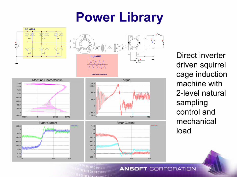
Direct inverter driven squirrel cage induction machine with 2-level natural sampling control and mechanical load

Power Library
BenefitsPredefined macro models of frequently used power electronic topologiesIncludes common control algorithmsAuxiliary elements, such as power grid models and loadsSystem level models for rapid computation of overall system behavior, power quality and control algorithmsEasy and intuitive graphical building blocks

Mechanical Elements LibraryRotational
Mass
Translational
Mass
Coordinate Transformation
Rotational-Rotational
Rotational-Translational
Translational-Rotational
SYMP Synchronous Machine Permanent Excitation
SYMP Synchronous Machine Permanent Excitation w Damper
Electrical Machines
DCMP DC-Machine Permanent Excitation
ASMS Slip Ring Induction Machine
Rigidity
Rigidity
Torque Source
Ground
Angular Velocity Source
Velocity Source
Ground
Force Source
Translational-Translational
Mechanical Systems
Applications:• Drive Trains• Electro-Hydraulic
Systems• Electro-Mechanical
Systems• Load Variations
Industries:• Automotive Suppliers• Drive Manufacturers• Industrial Automation• Defense• Aerospace

Mechanical Elements LibraryET1
Square_wave1.VAL
M
DCMP
Dcmp1J := 2m
STF
Stf1 M
DCMP
Dcmp2
J := 2m
M
DCMP
Dcmp3J := 2m
STF
Stf2J
Mas1
J := 10m
Dcmp1.VADcmp2.VADcmp3.VA
t
250.00
-250.00
0
-100.00
100.00
0 1.000.50
Dcmp1.OMEGADcmp2.OMEGADcmp3.OMEGAMas1.OMEGA
t
200.00
-200.00
0
-100.00
100.00
0 1.000.50
Mas1.MACX
t
1.25k
-1.25k
0
-500.00
500.00
0 1.000.50
Motor-generator combination driving a mass with limitations

Mechanical Elements Library
BenefitsNon-linear friction models incl. stick frictionNon-linear rigidity models incl. backlashFast computing 1D modeling approach based on SIMPLORER C-Code interfaceElectrical Machine model implementation with mechanical pins provide connectivity between electrical and mechanical worldSchematic based graphical modeling with mechanical building blocks
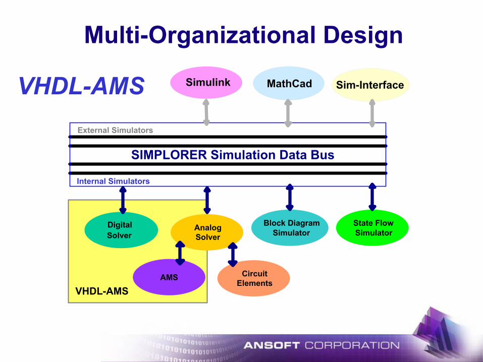
VHDL-AMS
Block DiagramSimulator
State FlowSimulator
SIMPLORER Simulation Data Bus
MathCadSimulink Sim-Interface
External Simulators
Internal Simulators
Multi-Organizational Design
DigitalSolver
Circuit Elements
Analog Solver
AMS
VHDL-AMS

VHDL-AMS SchematicFully supported by SIMPLORER Schematic
Embedded Editor with Syntax coloring allows to create models on sheet and in the ModelAgent
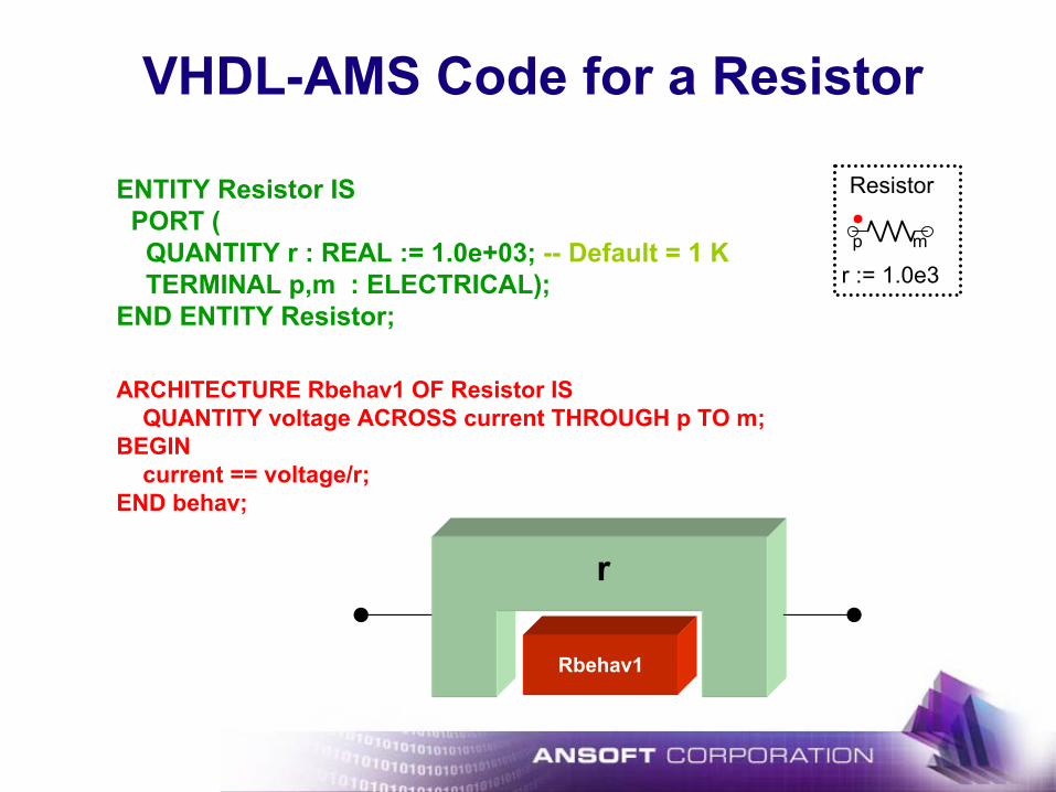
VHDL-AMS Code for a Resistor
ENTITY Resistor ISPORT (
QUANTITY r : REAL := 1.0e+03; -- Default = 1 KTERMINAL p,m : ELECTRICAL);
END ENTITY Resistor;
ARCHITECTURE Rbehav1 OF Resistor ISQUANTITY voltage ACROSS current THROUGH p TO m;
BEGINcurrent == voltage/r;
END behav;
mp
Resistor
r := 1.0e3
Rbehav1
r

Architecture 3Architecture 2Architecture 1
Entity and ArchitectureEntity
Interface description of a subsystem or physical deviceSpecifies input and output ports to the model
ArchitectureBehavior description of the modelCan be dataflow, structural, procedural, etcModeling can deal with both analog (continuous) and digital (discrete) domains
output portsinput ports
inout ports
Architecture 2Architecture 1
Entity

VHDL-AMS Basic LibraryOPEN!
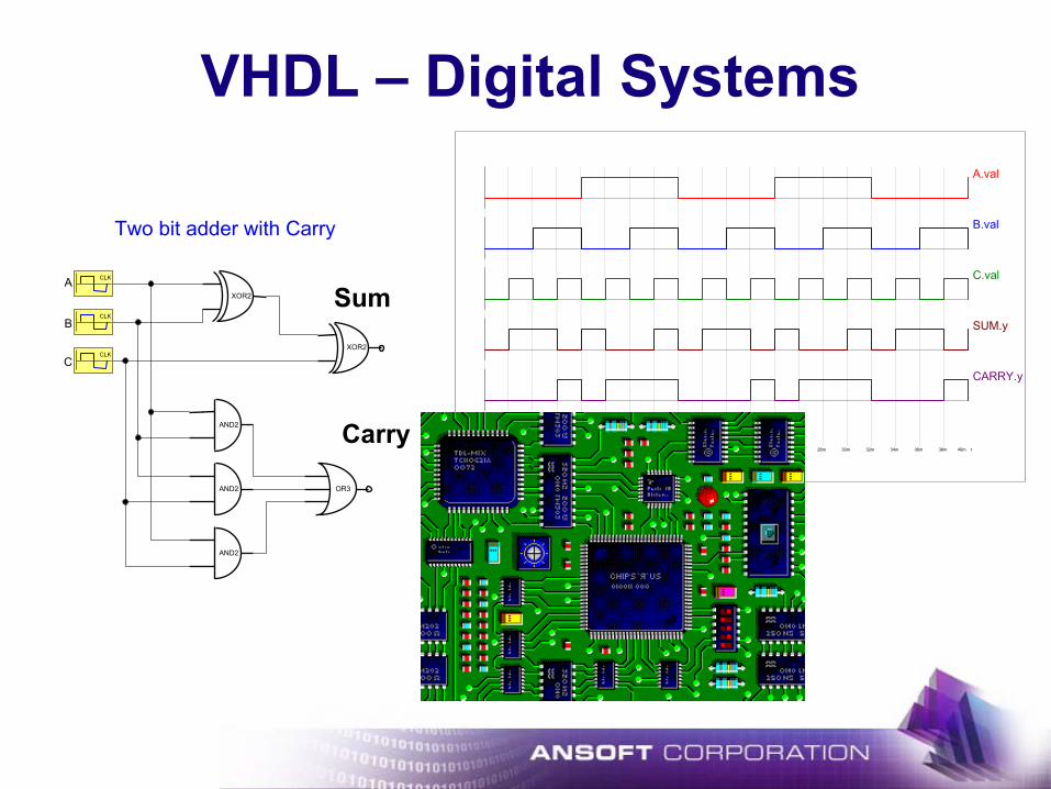
VHDL – Digital SystemsA.val
B.val
C.val
SUM.y
CARRY.y
t0 40m2m 4m 6m 8m 10m 12m 14m 16m 18m 20m 22m 24m 26m 28m 30m 32m 34m 36m 38m
CLKA
CLKB
CLKC
XOR2
XOR2
AND2
AND2
AND2
Two bit adder with Carry
Sum
Carry
OR3

VHDL – Digital SystemsComplete Automotive System Analysis across Domains
• ASICs
• Micro Controller
• FPGAs …
ECU
PTCU
MCUVHDL

VHDL-AMS Multi Domain Design
L
dia := 1len := 1/4
rho := MATH_PI
vol := 1b := 1
k := 10
EQU
crank_radius:= 0.2
pipe_area:= 0.05
Fluidic
torque force pressure
flow_meter rhyd1 lhyd1
chyd1
spring_rotb damp_rotb Tfm_rotb
ω+
vm_rotb
ω+
v_rotb
mass_rotb
CONST CONST
1/pipe_areacrank_radius
P
Sppeddamp_rotb.omega
t [s]
40
-40
0
-25
25
0 0.1k50
QuickGraph2flow_meter.q
t [s]
1Meg
-1Meg
0
0 0.1k50
Mechanic

VHDL-AMS
Component Providers
Subsystem Providers -Suppliers
OEMSystem Simulation
Drive CyclesFuel Economy
Multi Organization Design
Power TrainElectrical System
Sensors …
VHDL - AMS
VHDL - AMS
Solenoids, Motors, Battery, Sensors, Semiconductors,
Fuse …

DC Drive – VHDL-AMS Controller
L_R
0.3mL_S
L_T
ET1
ET2
ET3
R_R
10mR_S
R_T
t [s]
4.00e+001
0
2.00e+001
0
0
0.2
0.2
0.1
0.1
t [s]
1.50e+003
0
1.00e+003
0
0
0.2
0.2
0.1
0.1
motorcurrent
speed andreference speed
LIMIT
LIMITER
LL := 0UL := 20
GAIN
CONTR_OUT
THRES1 := -2.5
VAL1 := -1THRES2 := 2.5
VAL2 := 1
CONST
N_REF
1000
M
DCM
J := 4m
LA := 9.5mRA := 1.2
KE := 0.544
AAM1
t [s]
1.00e+003
0
5.00e+002
0
0
0.2
0.2
0.1
0.1
DCM.MI [N·m] TLoad.VAL
t [s]
2.00e+001
-1.00e+001
0
0
0
0.2
0.2
0.1
0.1
motor torqueandload torque
DC LinkVoltage andCurrent
D7
TR
TLoad
3
Bridge1
PIC
VHDL-AMS

DC Drive – VHDL-AMS Controller

ODE
Non-Electrical Elements
External Simulators
Electrical Components
µ-ControllerCode
C/C++ Interface

C/C++ Interface®
System Simulation
The Multi Domain Simulator
C/C++ makeDynamic
Link Library
.dll
Symbol Library
Symbol Editor

DC Drive – C-Code ControllerL_R
0.3mL_S
L_T
ET1
ET2
ET3
R_R
10mR_S
R_T
DCM.IA [A]
t [s]
3.00e+001
0
2.00e+001
0
0
0.2
0.2
0.1
0.1
DCM.N [rpm] N_REF.VAL
t [s]
1.50e+003
0
1.00e+003
0
0
0.2
0.2
0.1
0.1
motorcurrent
speed andreference speed
LIMIT
LIMITER
LL := 0UL := 20
GAIN
CONTR_OUT
THRES1 := -2.5
VAL1 := -1THRES2 := 2.5
VAL2 := 1
CONST
N_REF
1000
M
DCM
J := 4m
LA := 9.5mRA := 1.2
KE := 0.544
AAM1
Bridge1.Vout [V] Bridge1.Iout [A]
t [s]
1.00e+003
0
5.00e+002
0
0
0.2
0.2
0.1
0.1
DCM.MI [N·m] TLoad.VAL
t [s]
2.00e+001
-1.00e+001
0
0
0
0.2
0.2
0.1
0.1
motor torqueandload torque
DC LinkVoltage andCurrent
D7
TR
TLoad
3
Bridge1
PIC
PIC1
IGain := 2
PGain := 3
C-Code

DC Drive – C-Code Controller

SIM2SIMSIMPLORER to Simulink Interface
SIMPLORER
Simulink• Co-Simulation Interface
• Link blocks in both packages
• Using SIMPLORER's external simulator integration interface and S-function in Matlab
• Co-Simulation Interface is an open API that can be used for other simulation packages

Drive System Control
L_R
0.3m
L_S
L_T
ET1
ET2
ET3
R_R
10mR_S
R_T
GAIN
P_GAIN
KP := 3
II_GAIN
KI := 2
LIMIT
LIMITER
LL := 0UL := 20
CONTR_OUT
THRES1 := -2.5
VAL1 := -1THRES2 := 2.5
VAL2 := 1
CONST
N_REF
1000
M
DCM
J := 4m
LA := 9.5mRA := 1.2
KE := 0.544
A+ AM1
D7
TR
CONST
CLOCK
.1m
3
Bridge1TLoad

Drive System Control
L_R
0.3m
L_S
L_T
ET1
ET2
ET3
R_R
10mR_S
R_T
M
DCM
J := 4m
LA := 9.5mRA := 1.2
KE := 0.544
D7
TR
3
Bridge1TLoad
SiM2SiMSIMPLORER Link InterfaceSiM2SiM50
SIM2SIM1
SIM2SIM1.CS

Drive System Control

Complete Vehicle Simulation

SIMPLORER – Advisor Link

SIMPLORER – Advisor LinkSIMPLORER Single Voltage Electrical Automobile System Template
voltageregulator curve
Regulator
Generator
p
mGeneratorPower
p
m
BatteryPower
RearDefrost FrontHVAC
Engine BrakeLightsMisc ExternalLights
HeatedSeats
FrontWipers
RearWipers Radio
TurnSignalRadiatorFan
RearHVAC
genericgenerator
generator
Battery
Loads
Starter
p
m
®
Simulation properties:Step width max 100mStep width min 100uSimulation end time 1369
GAIN
Battery-+
pm
LoadPower
+ V
VM1
A
+
AM1
genericgenerator
generator1
SiM2SiMSIMPLORER Link InterfaceSiM2SiM50

ResultsGenerator Current
AM1.I
t
100.00
-50.00
0
0 793.91500.00
Speed in RPMSpeed
t
4.00k
-2.00k
0
2.50k
0 793.91500.00
Bus VoltageVM1.V
t
13.00
11.50
12.00
0 793.91500.00
Load Power
LoadPower
t
500.00
-1.50k
0
-1.00k
0 793.91500.00

Complete Set of AnalysesDC Analysis
NINV
INV
OUT
+
-
NSC_LM_7411
NINV
INV
OUT
+
-
NSC_LM_7412
NINV
INV
OUT
+
-
NSC_LM_7413
R1
10k
R210k
R310k
R410k
Rp15916
R1p10k
C1100p
C21n
E1 + V VM
Rfp
30k
R930k
R15916
OP: -0.00100994 V
OP: -0.00405477 V
OP: -7.9752e-006 V
OP: 0.999992 V
OP: 0.998936 V
OP: 3.99573 V
OP: 0.000980576 V
OP: -3.98873 V
OP: 1 V

E1 1
R1
500m
L1
R2 16
L2
C1 132.6u
31.83m
3.18m
OP: 0 V
OP: 0.969697 V OP: 0.969697 V OP: 1 V
Complete Set of Analyses
BodeC1.VGain
Phase
100
100
1k
1k
200
200
300
300
400
400
500
500
600
600
700
700
800
800
900
900
100
100
1k
1k
200
200
300
300
400
400
500
500
600
600
700
700
800
800
900
900
-28.01
-20.00
0.00
20.00
-28.01
-20.00
0.00
20.00
0.00
0.79
1.57
2.36
3.14
0.00
0.79
1.57
2.36
3.14
f [Hz]
f [Hz]
[dB]
[rad]
AC Analysis

Experiments
1D, 2D & 3D Parameter SweepMonte CarloSensitivityWorst CaseOptimization
Simplex AlgorithmSuccessive ApproximationGenetic Algorithms
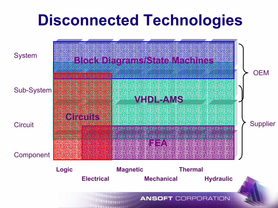
Electrical MechanicalThermalMagneticLogic
Hydraulic
Component
Circuit
Sub-System
System
OEM
Supplier
VHDL-AMS
Block Diagrams/State Machines
FEA
Disconnected Technologies
Circuits

FEA
VHDL-AMS
Circuits
Block D
iagram
s/
State M
achin
es
Integrated Technologies
SimulatorCoupling
Matlab/Simulink
MathCAD
Co-SimulationAdvisor
…

Integrated Design Environment
Efficien
cyCommunication
AccuracyStanda
rds


