Jordi Zaragoza
Power electronic topologies
for wind turbines
Source: ALSTOM WIND
Author: Jordi Zaragoza
XIX JORNADAS de CONFERENCIAS
JCEE’14

Jordi Zaragoza
Presentation of the wind systems: large numbers
Annual offshore wind installation (2011)
Size evolution of wind turbines over time
Source: EWEA
Source: EWEA

Jordi Zaragoza
Local wind turbine grid
Collecting
point
Wind farm
grid
interface
Transmission
system PCC
WT
General wind farm layout
Wind farm elements:
Wind turbines (WT). WT connected in parallel to radials.
Local wind turbine grid.
Collecting point. To increase the voltage for transmission.
Transmission system. HVAC or HVDC transmission.
Wind farm interface. To adapt the voltage, frequency and the reactive
power demand of the grid in the PCC.
Point of common connection.
Rules for connecting wind farms to the grid

Jordi Zaragoza
Fixed and variable speed wind turbines
Wind Turbine configurations
a) Wind turbine using an induction generation (IG).
b) Wind turbine using a doubly-fed induction generator (DFIG).
c) Wind turbine using a permanent magnet synchronous generator (PMSG).
2
Jordi Zaragoza
Fixed-speed wind turbines
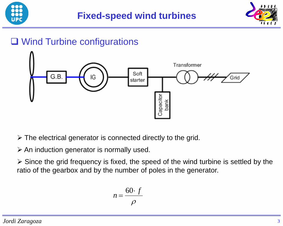
Wind Turbine configurations
The electrical generator is connected directly to the grid.
An induction generator is normally used.
Since the grid frequency is fixed, the speed of the wind turbine is settled by the
ratio of the gearbox and by the number of poles in the generator.
fn
60
3

Jordi Zaragoza
Fixed-speed wind turbines
Induction generator operating at fixed speed
Advantages:
- Robust design.
- No need for maintenance.
- Well enclosed.
- Produced in large series.
- Low price.
- Can withstand overloads.
Disadvantages:
- Uncontrollable reactive power consumption.
- Fixed speed means more mechanical stress.
Source: AEROSTAR
4

Jordi Zaragoza
Capacitor banks
Fixed-speed wind turbines
Capacitors banks compensate for reactive power from the induction generator.
Maxim use of the electrical grid is done operating at unity power factor.
C C C
Voltage
Current
5
Jordi Zaragoza
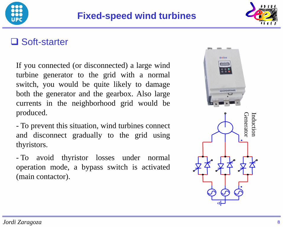
If you connected (or disconnected) a large wind
turbine generator to the grid with a normal
switch, you would be quite likely to damage
both the generator and the gearbox. Also large
currents in the neighborhood grid would be
produced.
- To prevent this situation, wind turbines connect
and disconnect gradually to the grid using
thyristors.
- To avoid thyristor losses under normal
operation mode, a bypass switch is activated
(main contactor).
Fixed-speed wind turbines
Soft-starter
8
Ind
uctio
n
Gen
erator

Jordi Zaragoza
Variable-speed wind turbines
Doubly-fed induction generator
A frequency converter control the currents in the rotor.
The slip of the rotor can change within a wider range.
Power converters have to stand only a fraction the nominal power (20% or 30%).
It is the most common topology produced by large manufacturers nowadays.
Less expensive compared to the full power converter.
Source: ALSTOM
WIND
9

Jordi Zaragoza
Variable-speed wind turbines
Multipole synchronous generator
Multipole synchronous generators may not need a gearbox (these generators
have a large diameter).
This is expected to be the most common wind turbine configuration in the
future.
ENERCON E-126 (7 MW)
10
Jordi Zaragoza
Variable speed
The frequency of the generator voltages can be different from the
electrical grid (50-60 Hz) and therefore the turbine speed can change.
Advantages:
- More energy production.
- Less mechanical stress.
- Reduce power fluctuation.
- Capacity of noise reduction.
- May have more control on the grid currents.
Drawbacks:
- The system requires power electronic converters.
- More expensive.
Variable-speed wind turbines
11

Jordi Zaragoza
Variable-speed wind turbines
Wind turbine components
12
Jordi Zaragoza
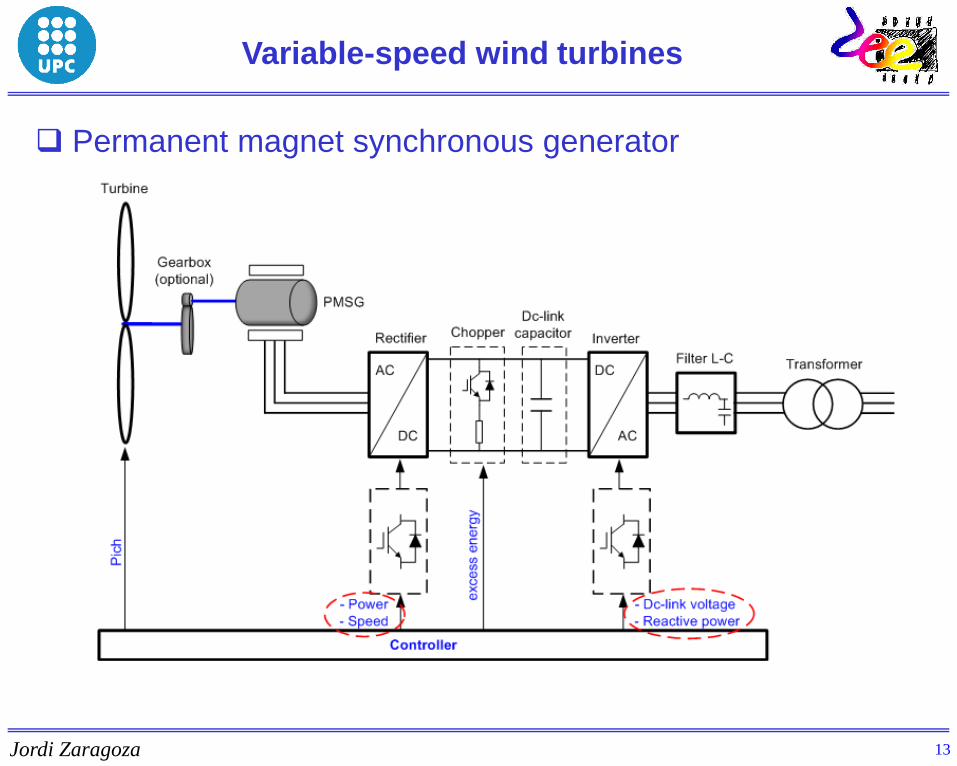
Variable-speed wind turbines
Permanent magnet synchronous generator
13
Jordi Zaragoza
Wind turbine system based on PMSG
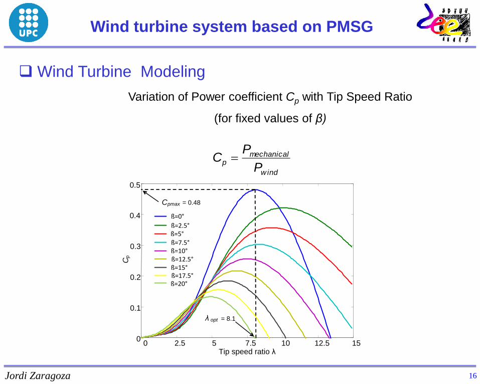
Wind Turbine Modeling
Variation of Power coefficient Cp with Tip Speed Ratio
(for fixed values of β)
2.5 7.5 10 12.5 15
Cp
5 0
0.1
0.2
0.3
0.4
0.5
Tip speed ratio λ 0
ß=0°
ß=2.5°
ß=5°
ß=7.5°
ß=10°
ß=12.5°
ß=15°
ß=17.5°
ß=20°
Cpmax
λ opt
= 0.48
= 8.1
wind
mechanicalp
P
PC
16
Jordi Zaragoza
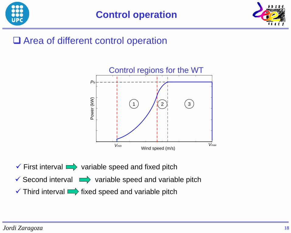
Second interval variable speed and variable pitch
Third interval fixed speed and variable pitch
First interval variable speed and fixed pitch
Area of different control operation
Control operation
PN
Vmin Vmax
Wind speed (m/s)
Po
we
r (k
W)
1 2 3
Control regions for the WT
18

Jordi Zaragoza
Source: L.M. Tolbert, “High Power Electronics for a Sustainable 21st Century,” NSF
Workshop for Sustainable Energy Systems, The University of Tennessee, Dec.
2000, Atlanta, Georgia.
Power electronic Semiconductors
Power Electronic Converter topologies of a
wind turbine
19

Jordi Zaragoza
AC/DC/AC
CvC2
C
r
Vdc s t
a
b
c
Wind-Turbine Two-Level Converter
vr
vs
vt
3*L
Multipole
Synchronous
Wind Turbine
Electrical
Grid
vC1
PMSG
Grid-Connected Two-Level Converter
Power Electronic Converter topologies of a
wind turbine
Back-to-back-connected conventional two-level
The maximum voltage that the transistors have to withstand is the total dc-
link voltage (Vdc).
Low quality output voltage spectra. This implies large values of the reactive
components to filter the output currents
21
Jordi Zaragoza
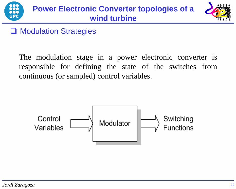
The modulation stage in a power electronic converter is
responsible for defining the state of the switches from
continuous (or sampled) control variables.
Modulation Strategies
Power Electronic Converter topologies of a
wind turbine
22
Jordi Zaragoza
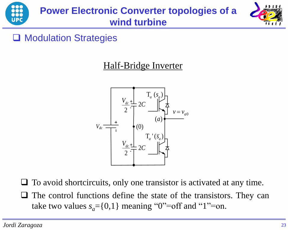
Half-Bridge Inverter
+
-
+
-
2
dcV
)0(
C2
C2
T ( )a as
T ' ( )a as
2
dcV
0avv )(a
Vdc
To avoid shortcircuits, only one transistor is activated at any time.
The control functions define the state of the transistors. They can
take two values sa=0,1 meaning “0”=off and “1”=on.
Power Electronic Converter topologies of a
wind turbine
Modulation Strategies
23

Jordi Zaragoza
If the upper switch is activated (ON state), the output
voltage becomes va0=+Vdc/2 independently of the current
direction.
02
dca
Vv v
+
-
+
-
2
dcV
)0(
C2
C2
aT
aT '
2
dcV
)(aVdc
02
dca
Vv v
+
-
+
-
2
dcV
)0(
C2
C2
aT
aT '
2
dcV
)(aVdc
The upper transistor
carries the output current
The upper diode
carries the output current
Power Electronic Converter topologies of a
wind turbine
Modulation Strategies
24

Jordi Zaragoza
If the lower switch is activated (ON state), the output
voltage becomes va0=-Vdc/2 independently of the current
direction.
02
dca
Vv v
+
-
+
-
2
dcV
)0(
C2
C2
aT
aT '
2
dcV
)(aVdc
02
dca
Vv v
+
-
+
-
2
dcV
)0(
C2
C2
aT
aT '
2
dcV
)(aVdc
The lower transistor
carries the output current
The lower diode
carries the output current
Power Electronic Converter topologies of a
wind turbine
Modulation Strategies
25

Jordi Zaragoza
Only one transistor from the leg can be activated at any time
(ON state).
The transistor activated defines the output voltage level,
independently of the output current direction.
Only two voltage levels can be obtained at the output
(va0=Vdc/2).
If sinusoidal waveforms are needed, the output variable
(voltage and/or current) has to be filtered.
The switching process is crucial (calculation of the ON and
OFF times) to achieve a good output voltage spectrum
which can be easily filtered. This process is determined by
the modulation strategy.
Remarks
Power Electronic Converter topologies of a
wind turbine
26
Jordi Zaragoza
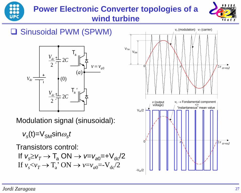
Modulation signal (sinusoidal):
vs(t)=VSMsinst
Transistors control:
If vsvT Ta ON v=va0=+Vdc/2
If vs<vT Ta’ ON v=va0=-Vdc/2
0ast
Vdc/2
VSM
VTM
vs (modulation) vT (carrier)
p 2p
v1 Fondamental component <> “instantaneous” mean value
0ast
p 2p
v (output voltage)
-Vdc/2
+
-
+
-
2
dcV
)0(
C2
C2
aT
2
dcV
0avv )(a
Vdc
aT '
Power Electronic Converter topologies of a
wind turbine
Sinusoidal PWM (SPWM)
27
Jordi Zaragoza
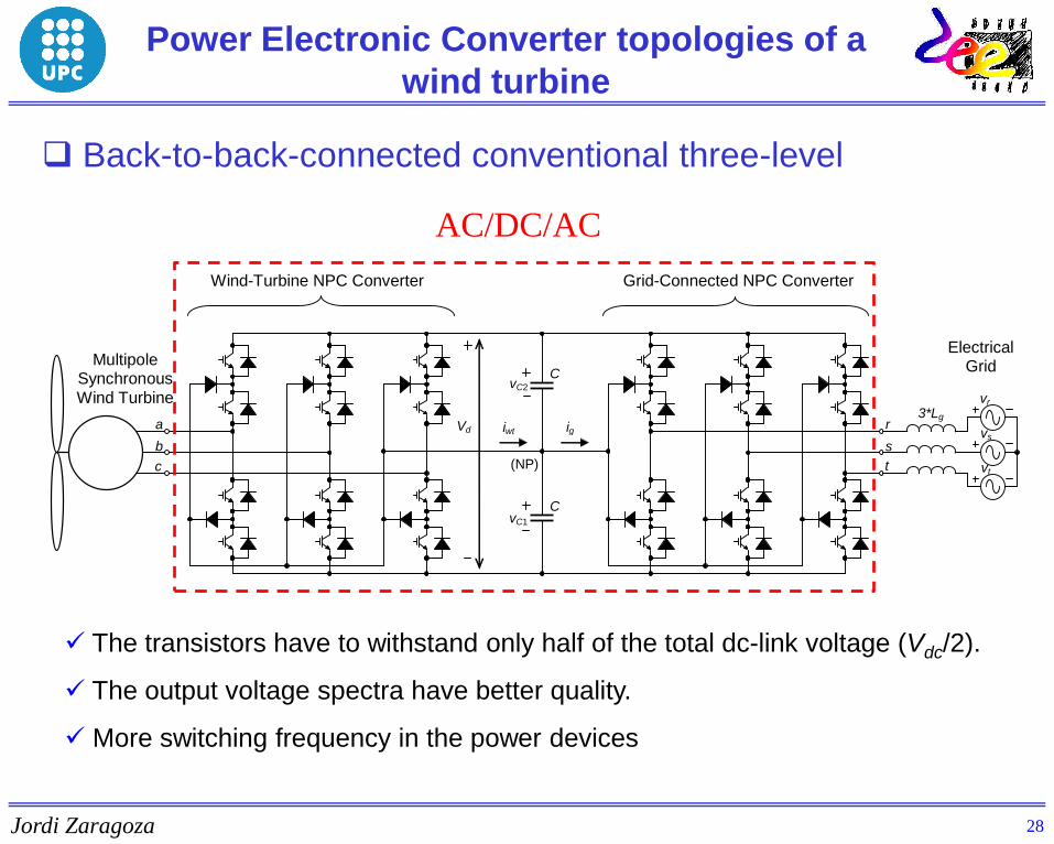
Back-to-back-connected conventional three-level
Power Electronic Converter topologies of a
wind turbine
(NP)
C vC2
vC1
C
r Vd
c s
t
a
b
c
Wind-Turbine NPC Converter Grid-Connected NPC Converter
vr
vs
vt
3*Lg iwt ig
Multipole Synchronous Wind Turbine
Electrical Grid
AC/DC/AC
The transistors have to withstand only half of the total dc-link voltage (Vdc/2).
The output voltage spectra have better quality.
More switching frequency in the power devices
28
Jordi Zaragoza
1
-1
a b c
Vdc
vC2
0
C vC1
C vC2
-1
0
1
c
b
a ia
ib
ic
sc-1
sc1
sc0
sb-1
sb1
sb0
sa-1
sa0
sa1
C vC1
Vdc
C
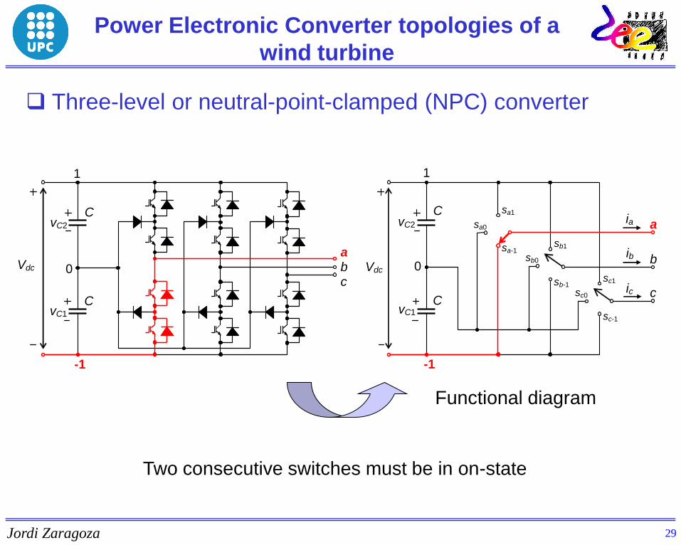
Functional diagram
Three-level or neutral-point-clamped (NPC) converter
Two consecutive switches must be in on-state
1
-1
a b c
Vdc
vC2
0
C vC1
C vC2
-1
0
1
c
b
a ia
ib
ic
sc-1
sc1
sc0
sb-1
sb1
sb0
sa-1
sa0
sa1
C vC1
Vdc
C
1
-1
a b c
Vdc
vC2
0
C vC1
C vC2
-1
0
1
c
b
a ia
ib
ic
sc-1
sc1
sc0
sb-1
sb1
sb0
sa-1
sa0
sa1
C vC1
Vdc
C
1
-1
a b c
Vdc
vC2
0
C vC1
C vC2
-1
0
1
c
b
a ia
ib
ic
sc-1
sc1
sc0
sb-1
sb1
sb0
sa-1
sa0
sa1
C vC1
Vdc
C
Power Electronic Converter topologies of a
wind turbine
29

Jordi Zaragoza
It is based on comparing sinusoidal modulation signals with a triangular
carrier of significantly larger frequency.
temps/T
0 0.005 0.01 0.015 0.02
-1
-0.8
-0.6
-0.4
-0.2
0
0.2
0.4
0.6
0.8
1
Sinusoidal pulse-width modulation SPWM
Vdc
i0
0
(NP)
C vC2
C
a
b c
vC1
sa4
sa3
sa2
sa1
sb4
sb3
sb2
sb1
sc4
sc3
sc2
sc1
-1
1
Control applied to define the state of the output voltages:
Reference above both carriers High level output (1).
Reference between both carriers Medium level output (0).
Reference below both carriers Low level output (-1).
Power Electronic Converter topologies of a
wind turbine
31
Jordi Zaragoza
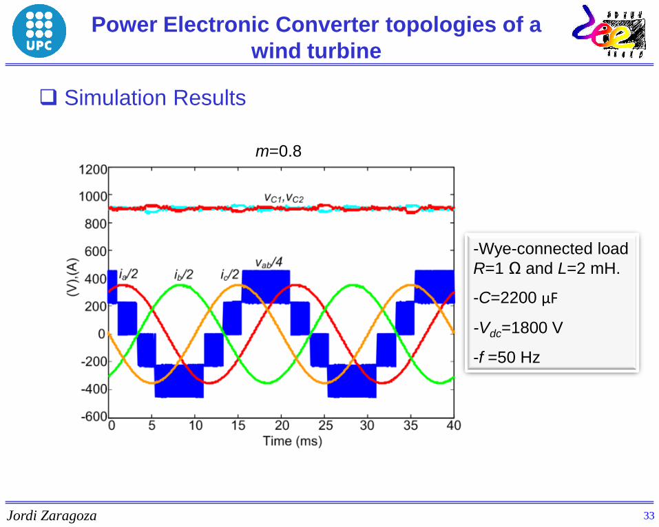
Simulation Results
m=0.8
-Wye-connected load
R=1 Ω and L=2 mH.
-C=2200 µF
-Vdc=1800 V
-f =50 Hz
Power Electronic Converter topologies of a
wind turbine
33


