
Power Control Algorithms for CDMA over
Wireless Fading Channels
University of Benghazi/Electrical and Electronic Department, Benghazi, Libya
Email: {elkour_05, abdulsalam_ambarek}@yahoo.com.
Abstract—The power control subject; is essential in mobile
communication systems, because it can mitigate the near-far
problem, increases the system capacity, improves the quality
of service, increases the battery life of the mobile terminal,
and decreases the biological effects of electromagnetic
radiation. In this paper, three different types of power
control algorithms will be studied which are; Distributed
Power Control (DPC) algorithm, Distributed Balanced
Algorithm (DBA), and Foschini’s and Miljanic’s Algorithm
(FMA), the Matlab code has been built for each of the three
listed algorithm and the results have been presented and
finally the comparison between the performance of each of
the three algorithms has been generated.
Key Words—power control, CDMA, FDMA, TDMA, quality
of service, capacity improvement near far effect.
I. INTRODUCTION
Direct Sequence Code Division Multiple Access
(DS/CDMA) is an emerging technology for civilian
wireless communication systems. CDMA offers
improved performance in terms of capacity or coverage
area over FDMA or TDMA based cellular networks,
another advantage is that CDMA combats multipath
fading due to the fact that the signal is spread over a large
bandwidth, and that each path can be tracked separately
at the receiver end and no frequency or time management
is required.
In the reverse link, where several asynchronous users
are communicating with the same base station and share
the same bandwidth, inter-user interference due to non-
zero crosscorrelation between different codes adds up in
power. The quality of each individual link degrades as the
number of users in the system increases
In FDMA and TDMA the number of available
frequencies and time slots are the limiting factors for the
number of users. Blocking occurs when the number of
users exceeds the available frequencies and time slots,
where as in CDMA blocking occurs when the tolerance
limit to interference is exceeded. Therefore in CDMA the
level of interference is the limiting factor.
In order to meet the increasing demand of mobile
subscribers for various services such as multimedia,
internet, transferring of big data like digital pictures, it is
crucial to have higher capacity and more severe Quality
Manuscript received May 27, 2013 revised July 20, 2013.
of Service (QoS) requirement, to meet this requirements
new technologies and improved resource management
including channel assignment, power control and handoff
are needed.[1], [2].
II. NEAR FAR PROBLEM
Consider that there are 2 mobile stations (MS)
transmitting at equal powers, but one is nearer to the base
station (BS) compared to the other as shown in Fig. 1.
The BS will receive more power from the nearer MS and
this makes the farther MS difficult to understand. As we
know, the signal of one MS is the noise for another MS
and vice-versa. So the Signal-to-noise interference ratio
(SINR) for the farther MS is much lower. If the nearer
MS transmits a signal that is orders of magnitude higher
than the farther MS then the SINR for farther MS may be
below detectability threshold and it would seem that the
farther MS is not at all transmitting. This situation is
called "near-far problem" and is less pronounced in GSM
than CDMA-based systems as the MS transmit at
different frequencies and timeslots in case of GSM.
To overcome this problem, a power control mechanism is
used so as closer MSs are commanded to use less power
so that the SNR for all MSs at the BS is roughly the same
[3], [4]
Figure 1. Near far effect
III. POWER CONTROL
Power control is a necessary element in all mobile
systems because of the battery life problem and safety
reasons, but in CDMA systems, power control is essential
because of the interference-limited nature of CDMA. The
overall objectives of power control can be summarized as
follows:
1) Overcoming the near-far effect in the uplink
2) Optimizing system capacity by controlling
interference
105
Lecture Notes on Information Theory Vol. 2, No. 1, March 2014
©2014 Engineering and Technology Publishing
doi: 10.12720/lnit.2.1.105-109
Hassan A. Elkour and Abdulsalam H. Ambarek

106
Lecture Notes on Information Theory Vol. 2, No. 1, March 2014
©2014 Engineering and Technology Publishing
3) Maximizing the battery life of mobile terminals
Power control in CDMA is a closed-loop PC which is
a combination of outer and inner closed loop control as
shown in Fig. 2. The inner (also called fast) closed loop
PC adjusts the transmitted power in order to keep the
received Signal-to-noise Interference Ratio (SINR) equal
to a given target.
This SINR target is fixed according to the received
BLER (Block Error Rate) or BER (Bit Error Rate). The
setting of the SINR target is done by the outer loop PC,
which is part the Radio Resource Control Layer, in order
to match the required BLER. Outer loop PC update
frequency is 10-100 Hz. The BLER target is a function of
the service that is carried. Ensuring that the lowest
possible SINR target is used results in greater network
capacity [3], [4]
Figure 2. Power control in CDMA system. In the receiver block, the received SIR and BER are estimated and used respectively for the inner-
loop and the outer-loop.
IV. POWER CONTROL ALGORITHMS
Power control is essential in mobile communication
systems, because it can mitigate the near-far problem,
increase the system capacity, improve the quality of
service, increase the battery life of the mobile terminal,
and decrease the biological effects of electromagnetic
radiation.
The objective of the power control algorithm is to keep
the transmitted power (for the mobile station in the uplink
power control and for base-station in downlink power
control) at the minimum power required to achieve the
target Quality of Service (QoS) in the system[5], [6].
Before giving a precise mathematical formulation for
the optimum power control problem, some notations and
definitions are given. Let the transmitted power control
vector be a Q-dimensional column vector P = [P1, P2...
PQ ]′ , where Pi is the transmitted power of user i. SINR
of user I is denoted by Γi .
Mathematically the power control problem is
formulated as follows:
The power control vector P that minimizes the cost
function
1
1Q
iiJ P P P
(1)
Γki
1
i ki
Q
j j kj ij i
PG
P G N
≥ Γmin , (2)
I =1…..,Q, k=1……M .
Pmin Pi Pmax , i=1,…….,Q. (3)
where:
1= [1, 1, 1……].
Q: Number of mobile stations.
M: Number of base stations.
Gkj: Channel gain between mobile station j and base
station k.
Ni: The average power of the additive noise at receiver i.
Pmax: Maximum power, which can be handled by the
transmitter.
Pmin: Minimum power, which can be handled by the
transmitter.
Γ min : Minimum predefined SINR
For simplicity, we will refer to user I without using the
subscript of its assigned base station. For example, we
will use Γi instead of Γki. If the SIN of user I, Γi < Γ min,
and the transmitted power Pi = Pmax, then user I (or some
other users) has to be dropped from this link. Another
important factor is the target SINR (ΓT ). It should be
noted that the superscript (T) means (Target). The dash ( )́
is used to indicate transpose operation. The difference
between the target SINR and the minimum predefined
SINR is called SINR margin.
The target SINR value is determined by the outer-loop
power control to achieve certain QoS in the cell. The
target SINR could be different from user to user because
it depends on the type of service requested by the user.
A. Centralized Power Control
If the information of the link gains and the noise levels
are available for all users, then the centralized power
control algorithm can be applied to solve the power
control problem given in (1),(2) . For noiseless case, Ni =
0, (2) becomes
Γi=
1
i ki
Q
j j kjj i
PG
P G
≥ Γmin , (4)
I =1…... Q, k=1……M
Equation (4) can be written in a matrix form as
P ≥ Γmin HP. (5)
where H is a nonnegative matrix with the following
elements
(H)ij= 0 i=j.
kj
ij
G
G i≠j. (6)
The problem is how to find the power vector P > 0
such that (5) is satisfied. Equation (5) can be written as
min
1I H P
(7)
The inequality is dropped in (7), since equality sign
holds for the minimum power vector. It is known from
linear algebra that a nontrivial solution of (7) exists if and
only if [ HI min
1 ] is a singular matrix. It is seen

from (7) that this happens, if
min
1
is an eigenvalue of H,
and the optimum power vector P is the corresponding
eigenvector. The power vector P should be positive.
Perron-Frobenius theorem [7] says that for a nonnegative
and irreducible QxQ matrix H there exists a positive
vector P associated with the maximum eigenvalue.
Λ* = ρ(H) = max ׀ λi׀ , i= 1,……,Q . (8)
where λi is the ith
eigenvalue of the matrix H, and ρ(H) is
the spectral radius of matrix H.
Based on this the maximum achievable SINR can be
expressed as
Now by considering the additive white noise at the
receivers, (2) can be written in a matrix form as
where u is a vector with positive elements ui specified by
It can be shown [7] that if ΓT <
)(
1
H then the matrix
[I- ΓTH] is invertible and positive. In this case, the power
vector P* is
The solution of the optimization problem posed in (1),
(3). [8].
The computation of the optimum power vector using
the centralized power control algorithm needs the link
gains of all users. This is computationally intensive;
moreover it is not feasible particularly in multi-cell cases.
Therefore it is common in practice to use a distributed
power control technique. Centralized power control can
be applied to test the upper bound performance using a
distributed technique in simulation.
B. Distributed Balancing Algorithm (DBA)
Zander has proposed a Distributed Balancing
Algorithm [8]. The method is based on the power method
for finding the dominant eigenvalue (spectral radius) and
its corresponding eigenvector.
The DBA algorithm is as follows
P(0) = P0 P0 ˃ 0
The algorithm starts with an arbitrary positive vector P
(0). The SINR level Γi(t) is measured in link i. If the
power control is for downlink, then the measurement of
the SINR is made at the mobile. The result is to be
reported back to the base station. The transmitter power
at the base station is then adjusted according to the DBA
in (13). If the power control is for uplink, then the
measurement of the SINR has to be made at the base
station.
The result has to be reported back to the mobile, and
each mobile station will adjust its transmitted power
according to the DBA.
Proposition (1)
Using the DBA algorithm (13) the system will
converge to SINR balance with probability one, i.e.,
lim 0,1,n
P t P t
lim 1, ,in
t r i Q
(14)
where γ* is the maximum achievable SINR, which is
equal to 1/λ*. As before, λ* is the spectral radius of the
nonnegative matrix H, and P* is the corresponding
eigenvector representing the optimum transmitted power.
Proof: See [8]
It is clear that the DBA uses only local SINR
information and utilizes an iterative scheme to control the
transmitted power. The main disadvantage of the DBA is
that its convergence speed is not satisfactory. If the
allowed speed of the iterations is not high enough, then
the distributed algorithm may result in an outage
probability much greater than the optimum value [9].
A. The Distributed Power Control (DPC)
It has been shown that the distributed power control
scheme for satellite systems can be applied to cellular
systems [10]. The results presented in [10] indicate that
the DPC scheme has the potential to converge faster than
the DBA scheme at high SINR’s.
The power adjustment made by the ith
mobile at the tth
time slot is given by
Pi(t+1) = β (t)
i
i
P t
t
, i=1,…..,Q , t=0,1,….. (15)
where β(t) is some positive coefficient chosen to achieve
the proper power control vector (not too large or too
small). In additive noise environment, it is very common
to select β (t)=ΓT [5].
C. Foschini’s and Miljanic’s Algorithm (FMA)
Foschini and Miljanic have proposed a simple and
efficient distributed power control algorithm [11]. The
proposed algorithm is based on the following continuous
time differential equation:
The steady state solution of the above differential
equation for user i is Γi = ΓT.
The speed of the convergence depends on the
coefficient β.
Define the total interference of user i:
Hen Γi from (2) becomes
107
Lecture Notes on Information Theory Vol. 2, No. 1, March 2014
©2014 Engineering and Technology Publishing
γ* =
1
=
1
H. (9)
[ I-T H ] P ≥ u. (10)
ui = i
ki
T
G
N, i= 1,…,Q, k=1,…,M. (11)
P*
= [ I-T H ]
-1u. (12)
Pi(t+1) = β Pi(t)
1
1i
t
. (13)
β ˃0, t=0,1,…. i=1,…..,Q
i = - β [ T
i ], β ˃ 0, τ ≥ 0. (16)
Ii(τ) = Q
kj jj iG P N
(17)
ki i
i
ki i
i Q
kj jj i
G PG P
G P N I
,
i=1…Q, k=1…M. (18)
Assuming that Ii(τ) and Gki(τ) are constant, substituting
(18) into (16) gives
Using (17) becomes
Using matrix notation one can write (20) as
P(τ) = - β[ I-ΓT H] P(τ) + β u. (21)
At the steady state, we have
P*= [I-Γ
T H]
-1 u. (22)
Proposition (5)
If there is a power vector P* , for which the target ΓT
values are attained, then no matter what is the initial Pi
(0), each of the Pi (τ) evolving according to (19) will
converge to P* of (22).
Proof: see [11].
The discrete form of (22) is
and the iterative power control for each user i is
V. SIMULATION ENVIRONMENT
To show the effectiveness of the proposed algorithms,
the scenario assumed 100 users uniformly distributed in
an area of 4 km2 with four base stations. Perfect handover
is assumed where each user is assigned to the base station
with the least gain loss. The channel is assumed static.
The simulation code assumes the radio channel with
propagation loss and shadowing. The received signal
power at base station [j] due to user [i] is assumed to
follow power law:
where Sji is the shadowing variable in the path from i-th
mobile station to j-th base station and it is assumed to be
a random variable with log-normal distribution and 6 dB
variance, dji is the distance between user i and base
station j, α=4. And the average additive noise in Watts at
the input of the base station is N=KToNFB, Where:
K=1.38*10-23
(Poltizman Constant), To =290 (K-
Temperature), NF=2dB (noise Figure), B=5MHz
(Bandwidth).
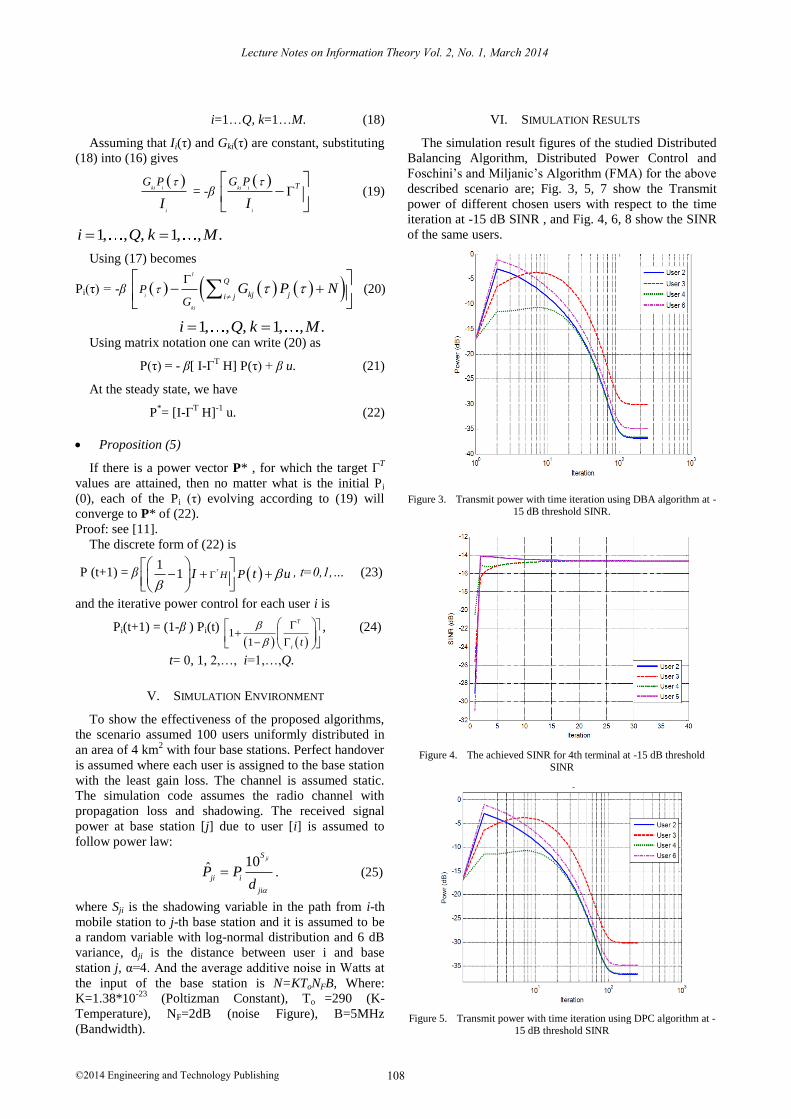
VI. SIMULATION RESULTS
The simulation result figures of the studied Distributed
Balancing Algorithm, Distributed Power Control and
Foschini’s and Miljanic’s Algorithm (FMA) for the above
described scenario are; Fig. 3, 5, 7 show the Transmit
power of different chosen users with respect to the time
iteration at -15 dB SINR , and Fig. 4, 6, 8 show the SINR
of the same users.
Figure 3. Transmit power with time iteration using DBA algorithm at -15 dB threshold SINR.
Figure 4. The achieved SINR for 4th terminal at -15 dB threshold
SINR
Figure 5. Transmit power with time iteration using DPC algorithm at -15 dB threshold SINR
108
Lecture Notes on Information Theory Vol. 2, No. 1, March 2014
©2014 Engineering and Technology Publishing
ki i
i
G P
I
= -β
ki i
i
TG P
I
(19)
1, , , 1, , .i Q k M
Pi(τ) = -β I
i
ki
Q
kj ji jP
GG P N
(20)
1, , , 1, , .i Q k M
P (t+1) = β 1
1T
H PI t u
, t=0,1,… (23)
10ˆjiS
ji i
ji
P Pd
. (25)
Pi(t+1) = (1-β ) Pi(t)
1
1
T
it
, (24)
t= 0, 1, 2,…, i=1,…,Q.

Figure 6. The achieved SINR for 4th terminal at -15 dB threshold
SINR
Figure 7. Transmit power with time iteration using FMA algorithm at -
15 dB threshold SINR
Figure 8. The achieved SINR for 4th terminal at -15 dB threshold SINR
VII. COMPARISON of THE THREE STUDIED
ALGORITHMS
Fig. 9, shows the compression between the three
studied algorithms which are; DPC ( ــــــــ curve), DBA ( -
- - - curve), and FMA ( ………. curve). From this figure
we can decide that the order of the base algorithms on the
speed and reaching to the optimum value of the power
are; DPC, DBA and FMA. Where all of the three
algorithms were reaching to the optimum power value,
which is the estimated base on CPC algorithm.
Figure 9. Convergence speed comparison between DPC,DBA and FMA
VIII. CONCLUSION
In this paper the comparison between the performance
of each of the three algorithms has been generated, thus
the DPC was the fastest over the other two algorithms
and the DBA was faster than FMA, considering the time
iteration slot to reach to the optimum power value.
REFERENCES
[1] F. N. Ayman, "Power control in wireless CDMA: Performance with cell site antenna arrays," IEEE Trans, 2002.
[2] A. Mudesir, ”Power control algorithm in CDMA system,” International University Bremen, 2004.
[3] K. Kim and I. Koo, “CDMA systems capacity engineering,”
Artech House Mobile Communications Series, British Library Cataloguing in Publication, 2005.
[4] J. Liberti and T. Rappaport, “Smart antennas for wireless communications,” Prentice Hall, 2000.
[5] H. N. Koivo and M. Elmusrati, Systems Engineering in Wireless
Communications, 2009 [6] M. S. Elmusrati, "Radio resource scheduling and smart antennas in
cellular CDMA communications system,” Helsinki University of Technology Control Engineering Laboratory Espoo, 2004.
[7] F. Gantmacher, “The theory of matrices,” vol. 2, Chelsea
Publishing Company, 1964. [8] J. Zander, “Distributed cochannel interference control in cellular
radio systems,” IEEE Trans. Veh. Technol., vol. 41, pp. 305─311, Aug 1992.
[9] T. Lee and J. Lin, “A fully distributed power control algorithm for
cellular mobile systems,” IEEE Trans. Commun., vol. 14, pp. 692─697, May 1996.
[10] S. Grandhi, R. Vijayan, and D. Goodman, “Distributed power control in cellular radio systems,” IEEE Trans. Commun., vol. 42,
pp. 226-228, Feb-Apr, 1994.
[11] G. Foschini and Z. Miljanic, “A simple distributed autonomous power control algorithm and its convergence,” IEEE Trans. Veh.
Technol., vol. 42, pp. 641─646, Nov 1993.
Dr. Abdulsalam H. Ambarek, associate professor in
Communicationsection, University of Benghazi – Libya, Electrical Department.
Mr. Hassan A. Elkour, Assistant Lecturer in Communication section,
University of Benghazi – Libya, Electrical Department.
109
Lecture Notes on Information Theory Vol. 2, No. 1, March 2014
©2014 Engineering and Technology Publishing


