
© 2012 Cisco and/or its affiliates. All rights reserved. This document is Cisco Public. Page 1 of 12
White Paper
PMU Networking with IP Multicast
Overview
This document proposes a network architecture which implements IP networking technologies, including IP
multicast, to help enable efficient transmission of phasor measurement unit (PMU) data for wide area
measurement systems (WAMS). Specifically, this document proposes the use of Cisco® IP Multicast technology for
the transport of PMU measurement data within a single network domain (that is, a single utility) or between network
domains (that is, multiple utilities). These domains can consist of service components such as phasor data
concentrators (PDC), data historians, and phasor gateways and others. This architecture allows each component
to continue serving as the host for PMU information while relying on a standards-based IP network for secure and
scalable transport. The IP network is now responsible for the receipt and re-transfer of PMU data. In this
architecture each of the service components acts as a repository which receives the data, from relevant PMUs, at
the edge of the network.
Today there are two proposed implementations for PMU data transfer, aside from the architecture proposed in this
paper. These include a middleware-based solution and the “PDC stacking” or “chaining” approach. These two
implementations have drawbacks which include:
● Lack of adequate scalability in the solution
● Few operational field deployments
● Propagation delays of PMU messages1
● Non-standard implementations which may vary widely across vendors
● Lack of multiple vendor sources for a standardized solution
● Lack of consistent and standard-based Internet security measures
Why deploy IP Multicast for transmission of PMU data? Some of the primary benefits of IP Multicast include:
● Vast scalability in terms of resource efficiency (for example, bandwidth), as well as a large number of
receivers that can be supported (essentially infinite).
● Proven technology with large install base
● Supports intra-domain and inter-domain architectures
● Simple adaptation of service component applications2
● Standards-based (IETF)
● Foundation for robust and scalable network security measures in order to be compliant with standards
and regulations
1 http://www.naspi.org/meetings/workgroup/2010_june/presentations/task_team_breakout/sisco_synchrophasor_20100608.pdf
2 Shown in the demonstration at NASPI FEB-2011

© 2012 Cisco and/or its affiliates. All rights reserved. This document is Cisco Public. Page 2 of 12
Implementation of the proposed IP Multicast architecture for PMU networking will have a significantly positive
impact on how the network performs. It can also reduce the complexity of managing the network. In addition, it can
help scale PMU deployments and application complexity.
A Network-Centric PMU Architecture
PMUs typically conduct measurements of the target subject and package these into one of various formats
such as:
● C37.118-2005, .1 and .2
● IEC 61850-8-1 GOOSE (Generic Object Oriented Substation Event) based on IEC 61850-90-5
● IEC 61850-9-2 sampled values based on IEC 61850-90-5
While there is discussion about the use of the IP protocol within various protocol documents related to GOOSE and
sampled values messages, these messages are typically encapsulated directly into Ethernet frames (without IP).
Use of Ethernet framing without IP constricts the scope for the transfer of data geographically. Adequate transport
of GOOSE and sampled values messages across the WAN will require use of an end-to-end transport protocol.
Both C37.118-2005 and IEC 61850-90-5 specify the use of the IP protocol transport (either IP Multicast or Unicast)
within the standards documentation.
Today PMU measurement messages transmitted using IP are transmitted using IP Unicast to pre-defined
receivers. These are typically PDCs or “super-PDCs” (integrated PDC functionality and service applications within
a single unit). The IP transport layer protocol most widely used is User Datagram Protocol (UDP). However, some
implementations utilize TCP for PMU control and configuration, and data transfer. GOOSE and sampled values
messages typically remain within the confines of the LAN. Implementations utilizing Ethernet VLAN-framed
messages are also used but still suffer from various limitations when implemented in WAN environments.
PDCs receive PMU messages and “concentrate” or combine them into a unified output stream. These PDCs play
an important role to time-synchronize the PMU messages by correlating their timestamps. The PDC then outputs
this combined message stream to another PDC (referred to as PDC stacking—when PMU messages traverse
multiple daisy-chained PDCs on their journey to the operations center). Eventually the PMU messages arrive at the
operations center. Along the path from PMU to the operations center, various actions such as local protection can
be taken based on an evaluation of the PMU measurements. These measurements are done based on PMUs from
within a utility or across utility boundaries. In addition, PMU measurement data may also travel to a regional entity
such as an Independent System Operator (ISO).
This dependence on PDC forwarding introduces a number of negative effects which can have an impact on delay,
jitter, scalability of the system, availability of the system, and others. One of the goals of the network architecture
proposed in this document is to minimize PDCs and other non-networking entities from the network path between
the PMU and any PMU message-consuming entity (PDCs, historians, middleware components, etc.). This
simplification will have a significantly positive impact on how the network performs, reduce the complexity of
management of the network, and help it to scale as the PMU network grows.
The PMU as a Multicast Source
The IP Multicast architecture assumes that the PMU is a multicast source. As such, the PMU will put out a
continuous stream of packets toward a pre-configured destination. Today PMUs transmit using IP Unicast.
Conversion from Unicast to Multicast can be implemented to accommodate legacy PMUs which cannot transmit
using IP Multicast.

© 2012 Cisco and/or its affiliates. All rights reserved. This document is Cisco Public. Page 3 of 12
The PMU messages are transmitted to the first-hop router (FHR) or gateway on the local network to which the
PMU is connected. This FHR is the first node in a multicast tree from the source (that is, the PMU) to the
destination. The destination can be a device such as a PDC or other application service component located at an
intermediate point in the network, at the operations center, or in another network domain. Once the PMU has been
told to begin transmitting, it will transmit to the FHR regardless of whether there are receivers. If there are no
receivers, the FHR will throw away the PMU packets until receivers come on-line.
All of the destinations to which the PMU will be transmitting are hosts located at the edge of the network rather
than being located inside the network and part of the forwarding path. These hosts are not participating in the
forwarding of the messages from the PMU. These hosts are called receivers in IP Multicast terminology. Figure 1
displays a typical IP Multicast tree and the downstream data distribution.
Figure 1. IP Multicast Tree and Downstream Data Distribution
Understanding Multicast Addressing
In order for PMU messages to be forwarded from the FHR to the destination, one or more destinations or receivers
must be active within the multicast implementation. In order to become active a receiver must signal to the network
that it wishes to receive traffic from a specific multicast source. This source is usually specified using what is called
an S,G pair. S represents the IP Unicast address of the source (that is, the PMU) and G represents the group
address which associates to the set of receivers that will receive traffic from the specific source.3 The group
address is also referred to as a multicast address. The group address is used in the multicast routing table to
inform downstream routers which specific multicast traffic must be transmitted in order to reach one or more
receivers. The source PMU (that is, the multicast source) will transmit each IP packet, containing a PMU message,
3 There are a number of different IP Multicast protocols, as well as implementations. This document refers to IP Multicast PIM-
SSM (Protocol Independent Multicast Source-Specific Model).

© 2012 Cisco and/or its affiliates. All rights reserved. This document is Cisco Public. Page 4 of 12
using the group address, G, in the IP destination address field and the source address, S, in the IP source
address field.
Becoming a Receiver
A receiver (for example, a PDC, a historian, or other application service component) that wishes to receive traffic
from a specific source PMU, say, source Sa, will utilize a protocol called Internet Gateway Management Protocol
(IGMP), Version 3. Version 3 supports the multicast model recommended by this proposed architecture known as
Protocol Independent Multicast-Source Specific Multicast (PIM-SSM). The receiver will signal to its local gateway
router (the gateway is also acting as the last-hop router [LHR]) that it wishes to receive traffic from the specific
source, Sa. The receiver must also specify the group address to which it will belong, Ga. This information, the (S,G)
pair, will need to be known in advanced to the receiver. How this information can be made available or published to
potential receivers is discussed later in the document.
Building the Multicast Tree (or Joining the Multicast Tree)
Once the potential receiver notifies the LHR that it wishes to become a receiver of traffic from Sa, the LHR begins a
process by which multicast protocol signaling travels in the upstream direction towards the source PMU. The
upstream path is determined by the unicast route to the PMU’s unicast source address Sa. If this is the first receiver
in the multicast group, Ga, the signaling will travel all the way back to the PMU source’s FHR. As the signaling
travels in the upstream direction toward the PMU source, the multicast process will be building a downstream route
to the receiver instantiating the group address, Ga, into the IP multicast routing table in each router along the path.
If this is not the first receiver to join the specific group, the multicast signaling will travel back toward the PMU
source until it arrives at a router, whereby it can join an existing multicast tree which is already transmitting data
from the specific PMU source Sa, towards Ga. From the source to the receivers for a particular (S,G) pair, the path
structure looks like a tree with branches pointing out to the various receivers which lie at the ends of the branches.
Figure 2 displays IP signaling in the upstream direction.

© 2012 Cisco and/or its affiliates. All rights reserved. This document is Cisco Public. Page 5 of 12
Figure 2. IP Multicast Signaling in Upstream Direction
This shows a major benefit of IP Multicast in that it does not implement multiple copies of the same data stream
from the source PMU. It implements a single stream in the form of a tree (an upside-down tree in the S to G
direction) which branches off at particular points in the network in order to efficiently reach all receivers or members
of the particular multicast group. A router where a tree branches off replicates the multicast packets out each
interface required in the downstream direction.
Receiving Data from the Multicast Source
Once the tree is built from the FHR to the LHR, multicast traffic can begin to be forwarded to the receiver or
receivers. Receivers can join and disconnect from the tree at any time. At the LHR, the traffic is forwarded onto the
local LAN to which the receiver is attached. Most receivers and sources are connected to LHRs and FHRs using
Ethernet LANs. In some cases PMUs are connected to concentrators using fiber pptic or copper serial links. The
concentrators output PMU signal traffic encapsulated in IP in Ethernet or directly in Ethernet frames. The Ethernet
frames in which the IP multicast traffic is encapsulated will implement an Ethernet multicast address. This will
signal to the local LAN computers that this is a multicast packet. The Ethernet multicast address is derived from the
IP multicast group address. Receivers will know which Ethernet multicast address to look for that corresponds with
the group address specified in the (S,G) pair or pairs they are working with. The receivers can verify the IP source
address when they pull the IP Multicast packet in for initial processing.
How to Implement IGMPv3 on a Windows or Linux Receiver Platform
Service components (that is, PDC, historian) can be integrated in the proposed PMU architecture by ensuring
IGMPv3 is supported within the operating system and software application on the receiving platform. This can be
as simple as modifying your application to make a call to a standard IGMPv3 routine in order to establish the
platform or application as an IP Multicast receiver. This has been recently accomplished by the following systems

© 2012 Cisco and/or its affiliates. All rights reserved. This document is Cisco Public. Page 6 of 12
vendors: SISCO4, OSISoft5, and InStep6, and has been demonstrated7 publicly at a recent North American
SynchroPhasor Initiative (NASPI) meeting.
Using IP Multicast to Scale the Network
As PMU data becomes more important to daily operations of the power utilities, PMUs will likely proliferate in
number as well as geographic location. PMU data increasingly will be used for not only monitoring, but also for
closed-loop control. As a result, consumption of PMU data is also likely to expand, resulting in the need to deliver
PMU data to many locations within the same network domain and to other network domains. Other network
domains include other utilities as well as ISOs, RSOs, academic institutions, and others.
As PMU networks grow in size and complexity, the need to scale the delivery of PMU data, as well as the reliability
of this delivery, will increase dramatically. IP Multicast is best positioned to help PMU networks scale.
Adapting PMUs to Work with IP Multicast
Native Multicast
Most, if not all, PMUs do not implement native IP Multicast for message transmission. In order to operate easily
within a multicast network, the PMU will be required to implement multicast natively. At a minimum, the following
capabilities will be needed:
● Transmission of a packet in multicast format
● Support for multiple group addresses
● Support for multiple source addresses may be useful in certain cases*
● Ability to compute UDP header checksum. The header checksum can also be left un-computed in cases
where intermediate routers cannot or are not configured to compute the checksum. Some PMUs compute
the UDP checksum when transmitting PMU messages.
Note: The middle two bullets imply that the PMU will be able to transmit multiple streams concurrently;
something they already do using IP Unicast. An example of this could be the need for transmitting messages to two
different groups of receivers having different data requirements. One group could reside on the local network
domain and the other which could reside on an external network domain. Each group could receive data from the
same PMU that had been tailored to suit their particular requirements.)
IP Unicast Control Plane
PMUs today typically implement a set of management control and response commands, as well as a PMU
message transmission function. This allows a separation of control and data plane functions which can be
beneficial for various reasons. An example of such control plane functions is described in the IEEE C37.118-2005
standard document. This document describes, CONFIGURATION I & II, COMMAND, and HEADER frames which
contain commands and responses that are used in conversations between the server (for example, PMU) and
client (that is, PMU consumer and possible PMU control entity). The data messages are referred to as DATA
frames. In an IP Multicast network architecture, a separate IP Unicast-based control plane is desirable for the
following reasons:
4 http://www.sisconet.com
5 http://www.osisoft.com
6 http://www.instepsoftware.com/
7 Shown in the demo at NASPI FEB-2011; See:
http://www.naspi.org/meetings/workgroup/2011_february/presentations/tech_demo_myrda_61850_90_5_interop_20110224.pdf
© 2012 Cisco and/or its affiliates. All rights reserved. This document is Cisco Public. Page 7 of 12
● Ability to implement a control entity separate from the client or receiver
● Ability to implement a separate security implementation for control and data functions
● It permits the implementation of a control entity within one network domain and a receiver or client entity in
a separate network domain
● Allows the implementation of three distinct PMU-related entities, including a management entity, as well
as the client and server entities. The management entity does not need to be one and the same as the
client entity.
Multicast Conversion for Legacy Equipment
PMUs Which Do Not Support the IP Protocol Suite
Legacy equipment which will never implement multicast capabilities can be supported by Unicast-to-Multicast
conversion capabilities. This capability is implemented within the Cisco 2010 Connected Grid Router. This
functionality will allow the PMU to continue to operate normally with respect to the control and data planes.
A pre-configured FHR can ingest one or more data IP/UDP Unicast streams from one or more PMUs and then
convert each of these streams to multicast. This newly-converted unicast-to-multicast traffic can then be forwarded
in the downstream direction once receivers have become active for the relevant (S,G) pair(s).
PMUs Which Support the IP Protocol Suite
In the case of PMUs which support direct Ethernet encapsulation of measurement messages (for example,
GOOSE or sampled values), and which require the transmission of these messages across the WAN, special
functionality such as that implemented in the SISCO IEC 61850-90-5 Bridge8 can be used to encapsulate the
GOOSE or sampled values messages into IP Multicast messages. The bridge consists of transmitter and receiver
components. The receiver at the far end of the WAN can de-capsulate and restore GOOSE or sampled values
messages to their original state (messages encapsulated directly into Ethernet frames) on the destination LAN.9
The SISCO 90-5 bridge works seamlessly with the IP Multicast implementation proposed here, taking advantage of
all the benefits it has to offer.
UDP and TCP Transport Protocols
Reliability, Availability, and Multicast
The basic implementation of this architecture recommends the use of UDP over IP Multicast. Unlike Transmission
Control Protocol (TCP), UDP is a non-reliable protocol. Many applications require PMU data to arrive with minimal
delay, as well as to arrive with consistent timing. TCP is implemented by end hosts, such as the PMU and the PMU
data receiver. When using TCP in today’s IP Unicast implementations, any PMU messages that do not arrive at the
receiver will be retransmitted by the originating host. When being retransmitted, a delay, roughly equivalent to the
round-trip-time (RTT) between transmitter and receiver is added to transmission time of the original PMU message.
Depending on the additional delay introduced by the retransmission, this delay may or may not be acceptable to
the consuming application for various reasons, including the ability to time-synchronize time-relevant messages
from multiple PMUs. In addition, TCP is not recommended for multicast because of the one-to-many nature of
multicast and the delays associated with retransmitting lost packets.
If the goal is to have a highly reliable and high-performance PMU network, there are many different ways this can
be achieved. The first step is to implement a well designed and operated network which minimizes transmission
8 http://www.sisconet.com
9 Shown in the demonstration at NASPI FEB-2011
© 2012 Cisco and/or its affiliates. All rights reserved. This document is Cisco Public. Page 8 of 12
interruptions, packet loss, and packet re-ordering, as well as delay. Various tools can be implemented to ensure
that PMU data arrives at the receivers reliably. These include the use of tools such as Pragmatic General
Multicast10 (PGM—IETF RFC-3208) for a reliable transport over multicast, as well as various live-live schemes in
which multiple copies of the PMU message streams can be implemented to ensure reliability of delivery. PGM is an
implementation developed for reliability specifically for multicast. TCP was designed primarily for use with IP
Unicast transmissions.
An additional tool, Real-Time Transport Protocol (RTP), encapsulated as IP/UDP/RTP, provides packet sequence
numbering and time-stamping. This could benefit network quality monitoring by providing feedback on the path
quality used by the PMU messages.
The live-live model implements identically-replicated IP packets from a PMU signal source. These duplicate
streams can be transmitted along the same network path but with a time-differential within the tolerance of PMU
measurements. Alternately, using traffic engineering techniques, including MPLS Point-to-Multipoint (P2MP)
functionality, the duplicate PMU signal feeds can be spacially displaced whereby they take two separate physical
paths through the network. Combining these techniques with RTP can make the live-live solution a very robust
implementation for PMU data availability.
Inter-Domain Communications
PMU Data Sharing
There is a requirement to share PMU data between utilities, and between utilities and ISOs and RSOs. In both
cases, PMU data will traverse network domain boundaries. As a result, there will be a need to integrate IP
Multicast information and signaling between domains.
Multicast Across Network Domains
The use of Protocol Independent Multicast source-specific mode, (PIM-SSM) makes multicast data transfer, and
the relevant signaling and tree setup, much easier than its predecessor, the Protocol Independent Multicast any-
source multicast (PIM-ASM) model. Source-specific mode (SSM) presents a marked improvement over any-source
multicast (ASM) in that Multicast Source Discovery Protocol (MSDP) is no longer necessary for inter-domain
source discovery. MSDP is a relatively complex protocol to configure and has limitations in scale when handling a
large amount of multicast source information. Because of this simplification, the need to no longer rely on MSDP is
a major benefit of using SSM, particularly for inter-domain multicast routing.
An important issue here is the ability to easily implement inter-domain multicast integration at the network edge (in
the gateway routers). As a result, the access by one utility or ISO, for example, to a second utility’s shared PMU
data can easily traverse the domain boundaries necessary for the data sharing to take place. Figure 3 shows what
interdomain sharing looks like.
10
PGM: http://www.cis.udel.edu/~kamboj/presentations/cisc856.pgm.ppt
© 2012 Cisco and/or its affiliates. All rights reserved. This document is Cisco Public. Page 9 of 12
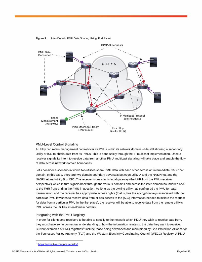
Figure 3. Inter-Domain PMU Data Sharing Using IP Multicast
PMU-Level Control Signaling
A Utility can retain management control over its PMUs within its network domain while still allowing a secondary
Utility or ISO to obtain data from its PMUs. This is done solely through the IP multicast implementation. Once a
receiver signals its intent to receive data from another PMU, multicast signaling will take place and enable the flow
of data across network domain boundaries.
Let’s consider a scenario in which two utilities share PMU data with each other across an intermediate NASPInet
domain. In this case, there are two domain boundary traversals between utility A and the NASPInet, and the
NASPInet and utility B or ISO. The receiver signals to its local gateway (the LHR from the PMU-receiver
perspective) which in turn signals back through the various domains and across the inter-domain boundaries back
to the FHR front-ending the PMU in question. As long as the owning utility has configured the PMU for data
transmission, and the receiver has appropriate access rights (that is, has the encryption keys associated with the
particular PMU it wishes to receive data from or has access to the (S,G) information needed to initiate the request
for data from a particular PMU in the first place), the receiver will be able to receive data from the remote utility’s
PMU across the utilities’ inter-domain borders.
Integrating with the PMU Registry
In order for clients and receivers to be able to specify to the network which PMU they wish to receive data from,
they must have some contextual understanding of how the information relates to the data they want to receive.
Current examples of PMU registries11 include those being developed and maintained by Grid Protection Alliance for
the Tennessee Valley Authority (TVA) and the Western Electricity Coordinating Council (WECC) Registry. A PMU
11
https://naspi.tva.com/pmuregistry/

© 2012 Cisco and/or its affiliates. All rights reserved. This document is Cisco Public. Page 10 of 12
Registry is one potential and relevant tool to provide such contextual relevance. As such, the PMU Registry could
integrate the (S,G) multicast information for the particular PMU within the metadata related to the registered PMU.
This way, potential receivers of this data can reference the PMU registry to glean the necessary data for them to be
able to establish themselves as a receiver of the data.
Cyber Security and PMU Data Transport Encryption
Group Encrypted Transport VPN (GETVPN)
Network security is an important requirement for synchrophasor networks as an essential part of the critical
infrastructure. Network security measures should be already integrated into the architecture from the beginning. IP
Multicast itself comes with features such as segmentation and path isolation that do meet typical security
requirements for PMU traffic.
PMU data transport security can be implemented using Cisco® GETVPN. GETVPN is based on a tunnel-less VPN
architecture. Main features, such as any-to-any instant connectivity, native routing (no overlays), advanced quality
of service (QoS), as well as efficient multicast replication are providing an excellent foundation for a scalable
architecture. GETVPN is based on various industry standards for both control and data planes. GETVPN will
encrypt PMU multicast packets between the FHR and the LHRs. It is possible to deploy GETVPN across network
domain boundaries in order to support secure transport for inter-domain PMU data exchange. Multiple groups can
be defined in order to support intra-domain PMU traffic as well as inter-domain PMU traffic. Two separate security
domains can be created to support different security requirements for inter- and intra-domain PMU transport.
GETVPN implements various features to support redundancy and availability to help ensure that the encryption
architecture is robust and survivable. GETVPN can be overlaid directly onto the IP Multicast architecture proposed
in this document.
Depending on the requirements, the security capabilities offered by GETVPN between the FHR and the LHRs can
be extended by using IEC 62351-6-2007 implemented by the publishers and subscribers of GOOSE messages
and sampled values data. IEC 62351-6:2007 provides cryptographic integrity for IEC 61850-8-1 GOOSE and
IEC 61850-9-2 sampled values. This approach supports all scenarios where perimeters are defined in an end-to-
end scenario.
IP Multicast Live Demonstration
This architecture was demonstrated at NASPI during the February 2011 meeting in Fort Worth, Texas. Figure 4
offers a snapshot of the demonstration presented at that meeting. A complete presentation covering the
functionality of this demonstration can be found at the NASPI website at (“Real-Time IEC 61850-90-5
Interoperability Demonstration”):
http://www.naspi.org/meetings/workgroup/2011_february/presentations/tech_demo_myrda_61850_90_5_interop_2
0110224.pdf

© 2012 Cisco and/or its affiliates. All rights reserved. This document is Cisco Public. Page 11 of 12
Figure 4. NASPI Demonstration Configuration
Relevant to the architecture proposed by this document, the above demonstration showed:
● The operation of the IP Multicast architecture (all data was transmitted over IP Multicast across wide-area
connectivity provided by Verizon Business,12 from EPRI13 Smart Grid facilities in Lenox, MA, Knoxville, TN
and Charlotte, NC to the demonstration venue in Ft. Worth, TX)
● IP Multicast infrastructure was implemented using Cisco14 2010 Connected Grid Routers (CGR 2010) and
Cisco 2050 Connected Grid Switches (CGS 2050) designed for use in power substations
● Implementation of IEC 61850-90-5 Bridge functionality to support GOOSE and sampled values message
transport over the WAN
● Integration of service component entities with the IP Multicast using IGMPv3. This required that the various
vendors—OSISoft, SISCO and InStep—modify the interface communications code in their applications in
order to have them interact with IGMPv3 to become active receivers.
Conclusions
The growth in renewable generation from wind and solar requires greater situational awareness of grid state due to
variability of these sources of generation. As a result, utilities are implementing communications and sensor
networks for more precise measurement and control of grid state. Synchrophasor networks are deployed to
improve visibility and control of wide regions of the electric grid. PMU deployments must be able to scale across
organizational boundaries to derive the benefits of wide area measurement. To achieve the level of scale and value
12
Verizon Business: http://www.verizonbusiness.com 13
Electric Power Research Institute: http://www.epri.com 14
Cisco: http://www.cisco.com

© 2012 Cisco and/or its affiliates. All rights reserved. This document is Cisco Public. Page 12 of 12
from PMUs, this paper proposes the use of proven networking technologies to scale and secure synchrophasor
deployments. IP multi-cast distributes PMU data efficiently across domains and will scale with the growth in
PMU deployments. GET VPN helps ensure a highly secure method for maintaining data integrity across wide
area networks.
The proposed network architecture can also help simplify the roll out of synchrophasor networks by helping to
minimize the number of PDCs and gateways required to transport and manage PMU data. By taking full advantage
of the IP network for PMU message transport, utility operators improve visibility and control of receivers, reduce
unnecessary hardware, (for example, PDC stacking), and reduce operations and maintenance expenses
associated with managing synchrophasor networks.
For More Information
For more information on Cisco’s Smart Grid strategy and solutions please visit http://www.cisco.com/go/smartgrid
For more information on Cisco 2010 Connected Grid Routers please visit
http://www.cisco.com/en/US/products/ps10977/index.html
Printed in USA C11-697665-00 01/12


