
1
Imagerie Médicale
Hervé DelingetteProjet Asclépios
Epidaure
26/09/2006 2
Plan
• Introduction aux images médicales :
• Introduction à la segmentation d’images• Méthodes de seuillage et classification
• Modèles déformables :
• Modélisation• Simulation de chirurgie
• Modélisation Cardiaque
• Croissance de tumeurs
26/09/2006 3
Imagerie Médicale
Roentgen, 1895
26/09/2006 4
Development of Computed Tomography
26/09/2006 5
Caracteristiques des images médicales (1)
Les niveaux de gris sont liées aux caractéristiquesphysiques des tissusqui peut également être reliéà un phénomène physiologique
Physique
Anatomie
Physiologie26/09/2006 6
Principales Modalités d’Imagerie
IRM
UltrasonScintigraphie
CT-Scanner
Densitéd’absorptionaux rayons X
Variations d’impédance Acoustique
Densitéd’isotopesinjectées
Densité et structure des
Protons

2
26/09/2006 7
Images Médicales 3-D• Représentation discrète d’une partie du corps qui est décrite
par une matrice à 3 dimensions (voxels)
• I(x,y,z) mesure certaines propriétés physiques ou chimiques du corps humain dans un élément de volume
M(i,j,k) = I (x,y,z)
26/09/2006 8
Images Médicales 3-D scanner IRM
Scintigraphie (TEMP,TEP) Echographie
26/09/2006 9
Tomodensitomètre X (Scanner)
• Densité d’absorption des rayons X26/09/2006 10
Tomodensitomètre X (Scanner)
Taille: 512 x 512 x 128Résolution: 0.5 x 0.5 x 1 mm
26/09/2006 12
Tomodensitomètre X (Scanner)
Axiale ou Transverse
26/09/2006 13
Imagerie par Résonance Magnétique
• Densité et structure des protons
3
26/09/2006 14
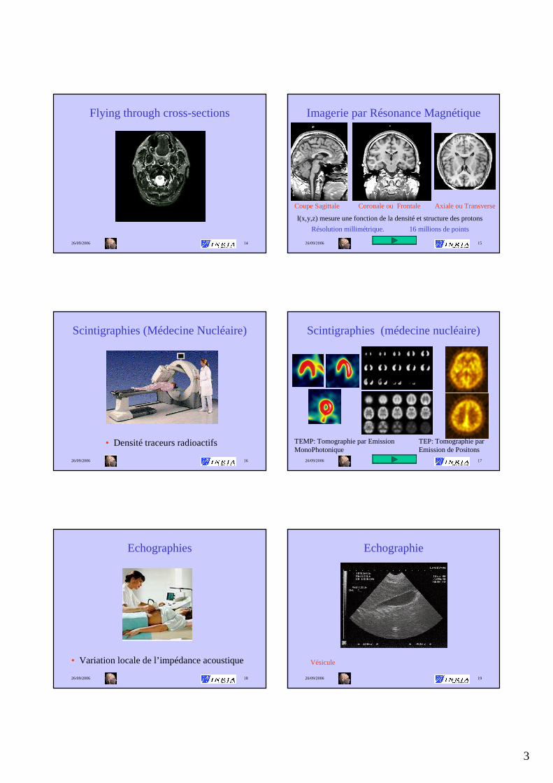
Flying through cross-sections
26/09/2006 15
Imagerie par Résonance Magnétique
Résolution millimétrique. 16 millions de points
Coupe Sagittale Coronale ou Frontale Axiale ou Transverse
I(x,y,z) mesure une fonction de la densité et structure des protons
26/09/2006 16
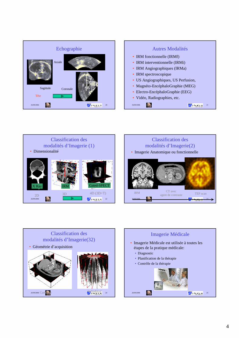
Scintigraphies (Médecine Nucléaire)
• Densité traceurs radioactifs
26/09/2006 17
Scintigraphies (médecine nucléaire)
TEMP: Tomographie par Emission MonoPhotonique
TEP: Tomographie par Emission de Positons
26/09/2006 18
Echographies
• Variation locale de l’impédance acoustique
26/09/2006 19
Echographie
Vésicule
4
26/09/2006 20
Echographie
Sagittale
Axiale
Coronale
Tête
26/09/2006 21
Autres Modalités
• IRM fonctionnelle (IRMf)
• IRM interventionnelle (IRMi)
• IRM Angiographiques (IRMa)
• IRM spectroscopique
• US Angiographiques, US Perfusion,
• Magnéto-EncéphaloGraphie (MEG)
• Electro-EncéphaloGraphie (EEG)
• Vidéo, Radiographies, etc.
26/09/2006 22
Classification des modalités d’Imagerie (1)
• Dimensionalité
2D 3D 4D (3D+T)
X Ray IRM Gated-SPECT
26/09/2006 23
Classification des modalités d’Imagerie(2)
• Imagerie Anatomique ou fonctionnelle
IRM CT avecagent de contraste TEP scan
26/09/2006 24
Classification des modalités d’Imagerie(32)
• Géométrie d’acquisition
Cartesian Cylindrical26/09/2006 25
Imagerie Médicale
• Imagerie Médicale est utilisée à toutes les étapes de la pratique médicale: • Diagnostic
• Planification de la thérapie
• Contrôle de la thérapie

5
26/09/2006 26
Vision Globale
Patient
DIAGNOSTIC
ScannerIRM
EchographieMN
Patient Virtuel
SIMULATION
Patient
THERAPIE
EchographieRadios X
VidéoIRMi
Per-opératoire
Pré-opératoire
Post-opératoire
26/09/2006 27
Imagerie Médicale(2)
• Les tendances en imagerie médicale :
• Meilleure qualité d’images
Moins d’artefacts et meilleur contraste
• Plus grande vitesse d ’acquisition
Imagerie 4D et moins d’artefacts dans les images 3D
• Meilleure résolution des images
Images plus détaillées et plus volumineuses
26/09/2006 28
Imagerie Médicale(3)
• Les images médicales ne sont pas utilisées de manières optimales :
••Visualisation 2D et partielleVisualisation 2D et partielle
• Peu ou pas dPeu ou pas d’é’évaluations valuations
quantitativesquantitatives
••Expertise importante pour Expertise importante pour
interprinterprééter les imagester les images
26/09/2006 29
Imagerie Médicale(4)
• Requiert des outils informatiques :
••Peux prendre en compte des Peux prendre en compte des images volumiques de grande images volumiques de grande tailletaille
••permet un analyse quantitative permet un analyse quantitative et reproductibleet reproductible
••Peux être intPeux être intéégrgréé dans le dans le systsystèème dme d’’ information de information de ll ’’ hôpital hôpital
Mais...Mais... Prend en compte les Prend en compte les ééchecs checs possibles du logicielpossibles du logiciel
••Supervision par un expert mSupervision par un expert méédical dical
Segmentation
1. Introduction
26/09/2006 35
Segmentation Task• Large number of available algorithms
• Possible classifications :• Genericvs task-oriented• Bottom-up vs Top-down approaches• Boundary vs Region approaches• Explicit vs Implicit A priori knowledge
• Validation
6
26/09/2006 36
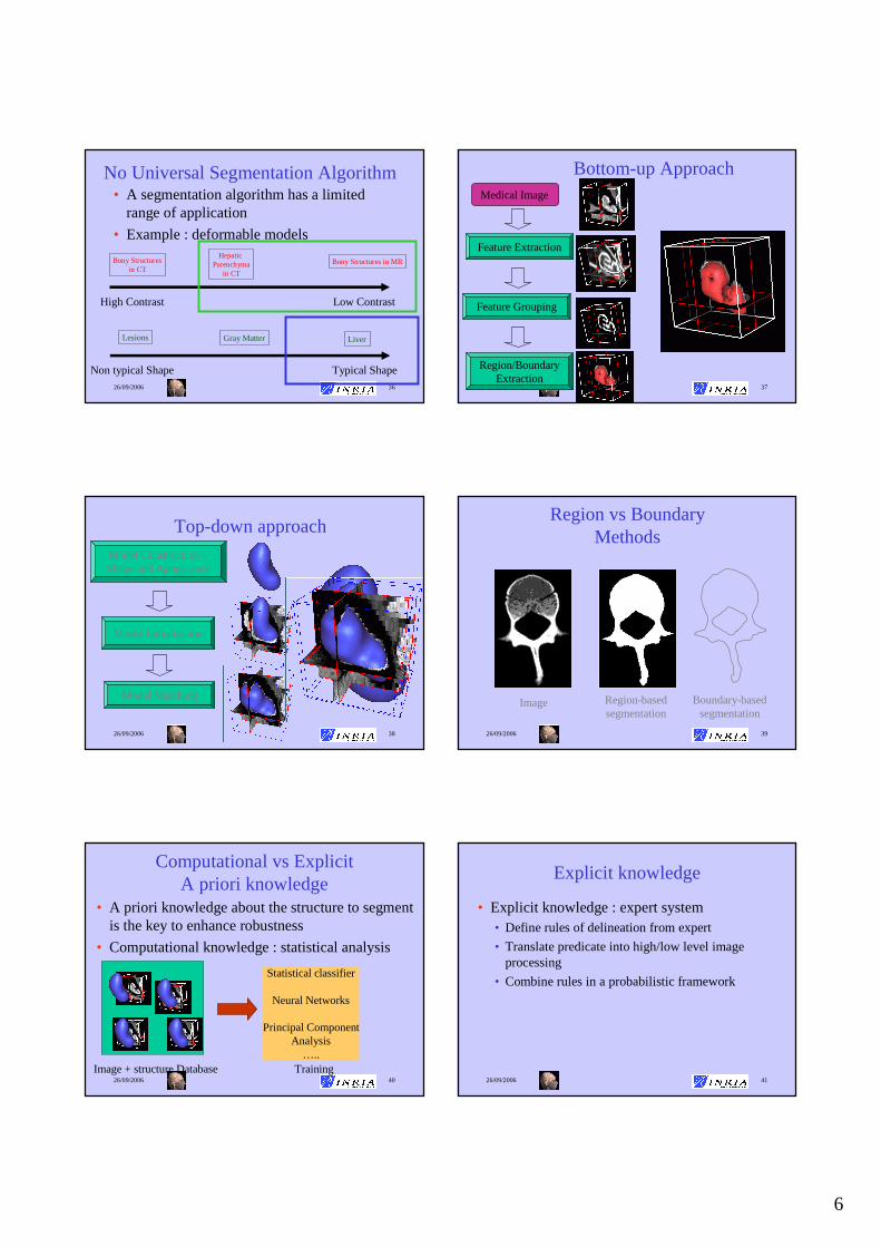
No Universal Segmentation Algorithm• A segmentation algorithm has a limited
range of application
• Example : deformable models
High Contrast Low Contrast
Bony Structuresin CT
HepaticParenchyma
in CT
Bony Structures in MR
Non typical Shape Typical Shape
Lesions Gray Matter Liver
26/09/2006 37
Bottom-up ApproachMedical Image
Feature Extraction
Feature Grouping
Region/BoundaryExtraction
26/09/2006 38
Top-down approach
Model Construction : Shape and Appearance
Model Initialisation
Model Matching
26/09/2006 39
Region vs BoundaryMethods
Region-basedsegmentation
Boundary-basedsegmentation
Image
26/09/2006 40
Computational vs Explicit A priori knowledge
• A priori knowledge about the structure to segment is the key to enhance robustness
• Computational knowledge : statistical analysis
Image + structure Database
Statistical classifier
Neural Networks
Principal ComponentAnalysis
…..Training
26/09/2006 41
Explicit knowledge
• Explicit knowledge : expert system• Define rules of delineation from expert
• Translate predicate into high/low level image processing
• Combine rules in a probabilistic framework

7
26/09/2006 42
Validation of Segmentation Algorithm
• Intrinsic Validation: comparison against• Observation of Physical Phantoms
• Difficult and expensive to build• May not be representative of real data
• Simulated images (MNI Brain Atlas,…)• Difficult to simulate artefacts
• Segmentation of experts • Large inter and intra variability of segmentation
across experts• May not be representation of population variability
26/09/2006 43
How to judge segmentations of the peripheral zone?
0.5T MR of prostate Peripheral zone and segmentations
26/09/2006 44
Validation of Segmentation Algorithm (2)
• Extrinsic Validation: comparison againstother segmentation algorithms• Only possibility when no ground truth exists
(Inter-patient registration of images) or when itnot available
• Estimate consistency, repeatability and size of convergence basin
26/09/2006 45
Two Segmentation Methods
Focus on 2 segmentation methods :
•Bottom-up : Thresholding /Classification
•Top-down :3D and 4D deformable models
Thresholding /Classification Deformable Models Markov Random FieldShape Information None Important localIntensity Information Essential Important ImportantBoundary / Region Region Boundary Region
26/09/2006 46
Deux Méthodes de Segmentation
Description de 2 méthodes de segmentation :
•Basée Voxel: Thresholding /Classification
•Basée Modèle:Modèles déformables 3D et 4D
Thresholding /Classification Deformable Models Markov Random FieldShape Information None Important localIntensity Information Essential Important ImportantBoundary / Region Region Boundary Region
Segmentation
2. Seuillage/ Classification

8
26/09/2006 48
• Idée principale:
une structure est uniquement caractérisée par ses niveaux de gris dans l’image
• Algorithme de seuillage élémentaire : • Seuillage entre deux niveaux de gris (fenêtrage)
• Opérations de morphologie mathématique• Erosion et Dilation
• Fermeture et Ouverture
• Extraction de composantes connexes
Seuillage et Classification
Valide pour les structures fortement contrastées
Images Fortement Contrastées (1)
Exemple : Image scanner du bassin
Seuillage interactif
Image Seuillée
Images Fortement Contrastées (2)
Image après opérations de
morphologie mathématique
Isosurface
26/09/2006 51
Thresholding + mathematicalmorphology + connected components
26/09/2006 52
Limitation of thresholding
Thresholding :
• Choice of threshold can be computed fromgrey-level histogram
• Does not assume any spatial correlation of voxel intensity
• Does not take into account the effect of partial volume effect (PVE)
Use of classification methods26/09/2006 53
Classification Method• It is often not valid to consider that a voxel belongs to a
single tissue type.
• It is therefore reasonable to estimate that each voxelx has a probabilitypk(x) of belonging to a tissue class k (1≤ k ≤ K)
1)(1
=∑=
K
kk xp
CT scanimage ofthe Liverwith 3 tissue classes

9
26/09/2006 54
Classification des tissus du cerveau
• Application pour l’IRM du cerveau
Fluide Céphalo-rachidien
Matière Blanche
Matière Grise
Courtesy of D. Vandermeulen
26/09/2006 55
• Various classification methods :• Fuzzy c-means
• General classification approach
• Non parametric
• EM Algorithm• Parametric approach (mixture of Gaussians)
• Can take into account bias field
• Curve fitting• Use a hierarchical approach
• Non-linear optimization
Classification Method (2)
26/09/2006 56
Isosurface et Isocontours (1)
• Etape de polygonalisation :
Image Voxelbinaire ou
avec niveaux de gris
Surface Discrète (triangulation)
26/09/2006 57
Isosurface et Isocontours (2)
• Plusieurs stratégies :• 1) Image Binaire ⇒ extraction du bord des voxels
• 2) Extraction de contours puis connexion des contours par une surface
• 2) Image Binaire ou niveaux de gris ⇒ extraction d’isosurfaces associées à un seuil c
En 2D, Extraction d ’isocontours I(x,y)=c
En 3D, Extraction d ’isosurfaces I(x,y,z)=c
26/09/2006 58
Isosurface et Isocontours (3)
• Choix du seuil c :• peut-être une valeur flottante
• pour la plupart des algorithmes, on utilise une valeur non-entière
• Propriétés des isosurfaces :• surfaces fermées ou avec une seul bord
correspondant au bord de l’image
• La normale à la surface est donnée par le vecteur gradient de l’image
26/09/2006 59
Extraction d’Isocontour
• Calcul en 2D d’un isocontour• Utilisation de la dualité entre pixels et points
• On calcul l’intersection de l’isocontour avec chaque pixel par une interpolation ( linéaire )
I=13
I=25I=32
I=18
C=15.5Intersection avec
l ’isocontour

10
26/09/2006 60
Extraction d’Isocontour (2)
• Calcul de l’isocontour à l’intérieur de chaque pixel :
• Algorithme :
Calcul des intersections
Détermination des pixels intersectés
Calcul de l ’isocontourpour chaque
pixel
26/09/2006 61
Extraction d’Isocontour (3)
• Ambiguité : 2 choix sont possibles:
• On utilise l’un ou l’autre ou la moyenne des intensités au centre du pixel :
Segmentation
2. Seuillage/ Classification
26/09/2006 70
Segmentation d’images à l’aide de modèles déformables
• Un modèle déformable est un récipient pour stocker de l’information a priori sur la géométrieet l'apparencede structures anatomiques
• Deux niveaux de connaissance a priori:
Forme
Apparence
Faible Connaissance a priori
Contrainte de continuité C1 ou C2
Initialisation avec formes génériques (sphère, …)
Utilise information de gradientet/ou intensité
Contrainte de Forme
Initialisation avec forme moyenne
Utilise profils d’intensité ou appariement de blocs
Grande Connaissance a priori
26/09/2006 71
Faible connaissance A Priori
•Valide pour des structures fortement contrastées
•Peut demander une intervention de l’utilisateur 26/09/2006 72
Forte connaissance A Priori
•Valide pour une structure donnée et une modalité donnée
•Plus robuste à l’exception des formes « anormales »

11
26/09/2006 74
Segmentation: endocranium
CT scan image, Bony structures
Time of convergence : 13,8 s 1169 3cmmodel:mold: 1150 3cm
26/09/2006 75
Visible Human
Joseph Paul Jernigan (died August 5th 1993)
26/09/2006 76
Reconstruction du Foie
Deformation à partir d ’un modèle de référence issu du «Visible Human Project »
26/09/2006 77
Segmentation: foie
Image scanner de l’IRCAD, extraction du foie
Temps de convergence: 2 mn 12 sExtraction des segments de Couinaud
26/09/2006 78
Liver SegmentationVariabilité anatomique du FoieVariabilité anatomique du Foie
26/09/2006 79
Deformable Model Geometry (3)
Deformable Models
Continuous Models
DiscreteModels
ExplicitRepresentation
Implicit Representation
DiscreteMeshes
ParticleSystems
Level-Sets
Algebraic CurvesFinite-Elements
Modal Decomposition
Simplex Mesh Spring-MassModels
DeformableTemplates
[Montagnat2001]

12
26/09/2006 80
Deformable models• Level-sets
• Curve/Surface C (in ℜ2/ ℜ3) that corresponds to an iso-level of a surface/hypersurface (in ℜ3/ ℜ4)
• Implicit representation
{ }0),,(|),()( == tyxuyxtC 0=∇+ uFu t
Modélisation
3. Computational Models of the Human Body
26/09/2006 85
Modeling Levels
Shape
Surface
Volume
MorphologyAnatomy
Kinematics
Temperature
Deformation
Forces
Electromagnetism
Physics
Pathology
Cells VascularSystem
RespirationPhysiology
26/09/2006 86
in vivo Data
coupling
in vitro
Experiments
Physiological
Medical
Imaging
Clinical
Measures
Physical
Computational
Models
Anatomical
Modeling and Imaging
Validation
Simulation
Estimation
Image processing for model validationSimulation for planning or prediction of therapiesPhysical parameters recovery from models and images
Geometry
Mesh construction from medical images
26/09/2006 87
Example of Computational Models of the Human Body
• 3 applications of human modeling
Application Type OrganReal/Time Constraint
Image Interaction
Physiological Modeling
Surgery Simulation Liver Yes Validation No
Diagnosis & Therapy Planning
Heart NoImage
SegmentationYes
Prediction of outcome Brain No Validation No
Surgery Simulation
Acknowledgments: •Clément Forest, Guillaume Picinbono, Stéphane Cotin, Jean-ChristopheLombardo, Nicholas Ayache
• INRIA projects member of the AISIM collaborative action (Imagis,
•Sharp,Macs)
•IRCAD
13
26/09/2006 89
Need for Training
Hand-eye Synchronisation
Camera being manipulated by an
assistantLong instruments
going through a fixed point in the abdomen
26/09/2006 90
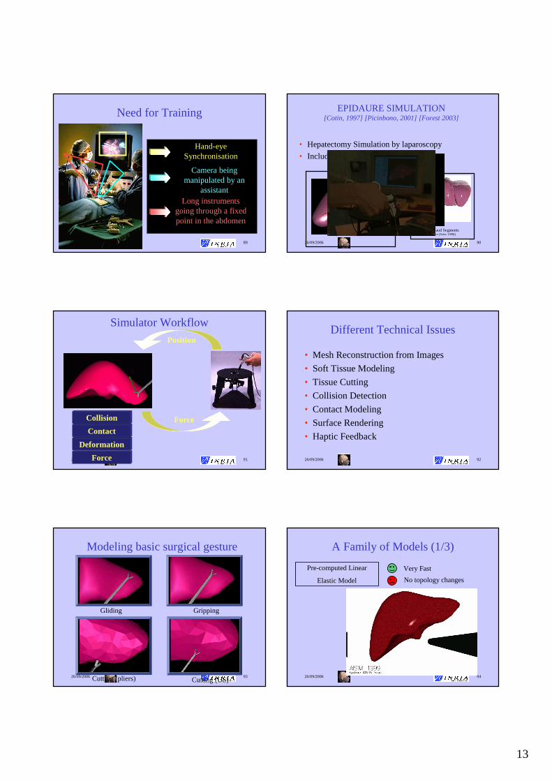
EPIDAURE SIMULATION [Cotin, 1997] [Picinbono, 2001] [Forest 2003]
• Hepatectomy Simulation by laparoscopy
• Include vessels and hepatic parenchyma
Couinaud Segments(source [Soler, 1998])
26/09/2006 91
Simulator WorkflowPosition
Force
Force
Deformation
Contact
Collision
26/09/2006 92
Different Technical Issues
• Mesh Reconstruction from Images
• Soft Tissue Modeling
• Tissue Cutting
• Collision Detection
• Contact Modeling
• Surface Rendering
• Haptic Feedback
26/09/2006 93
Modeling basic surgical gesture
Gliding Gripping
Cutting (pliers) Cutting (US)26/09/2006 94
A Family of Models (1/3)
Pre-computed Linear
Elastic Model
Very Fast
No topology changes

14
26/09/2006 95
A Family of Models (2/3)
Elastic Model
« Tensor-Mass »
Topology Changes
Limited to small displacements
26/09/2006 96
A Family of Models (3/3)
Large DisplacementsNon-Linear ElasticModel Small Deformations
26/09/2006 97
Complete Simulation
26/09/2006 98
Complete Simulation
Cardiac Modeling
CARDIOSENSE3Dhttp://www.inria.fr/CardioSense3D
Acknowledgments: •Maxime Sermesant, Valérie Moreau, Nicholas Ayache• INRIA projects member of the ICEMA collaborative action (Sosso, Macs, Caiman, University of Nantes),•NIH (Elliott Mc Veigh), Guy’s Hospital (D. Hill)•Philips Research France
26/09/2006 100
Electrical Model
Electromechanical
Model of the Heart
Electromechanical
Coupling
Anatomical Model
ElectroCardioGram
Patient
Data
Imagerie
Parameters
Medical
Simulatorpathology simulation
intervention planification
cardiac function :
• ejection fraction
• wall thickness
• strain, stress

15
26/09/2006 101
Myocardium Geometry
• Obtained from High Resolution Post-Mortem MRI of canine heart
Courtesy of Hsu, Duke University
Other Data available, Courtesy of P. Hunter, Auckland University
26/09/2006 102
Fiber Directions (canine Data)
• From high resolution Diffusion Tensor MRI
E.W. Hsu and C.S. Henriquez, Myocardial fiber orientation mapping using reduced encoding diffusion tensor imaging, Journal of Cardiovascular Magnetic Resonance, 2001.
26/09/2006 103
Geometrical Model of Human Heart
Finite Element Mesh Fiber Directions
26/09/2006 104
Different Levels of Modeling
• Geometrical Modeling
• Electrical Propagation
• Mechanical Coupling
• Parameter Identification
26/09/2006 105
Heart Electrical Activity
Atrialdepolarisation
Ventriculardepolarisation
Ventricularrepolarisation
26/09/2006 106
Electrical Model
• Action potential u computation: 2 variables FitzHugh-NagumoReaction-Diffusionsystem
u action potentialD diffusion tensorf ionic currentz repolarization variableb repolarisation ratec repolarisation decay
( ) ( )
( )
−=∂∂
−+∇=∂∂
czubt
z
zufuDdivt
u
Or R. Aliev and A. Panfilov : A Simple Two-variable Model of Cardiac Excitation, Chaos, Solitons & Fractals, Vol 7, No 3, pp. 293-301,1996

16
26/09/2006 107
Electrical Simulation
Anisotropic model (fiber geometry + Purkinje network)
=25.000
025.00
001
D
26/09/2006 108
Comparison of Isochrones
Durrer et al.
ICEMA at INRIA
26/09/2006 109
Different Levels of Modeling
• Geometrical Modeling
• Electrical Propagation
• Mechanical Coupling
• Parameter Identification
26/09/2006 110
Biomechanical Properties
The myocardium is composed of muscle fibre bundles:
It is an active non-linear viscoelasticanisotropic incompressiblematerial.
26/09/2006 111
Excitation-Contraction CouplingFrom Bestel-Clément-Sorine, MICCAI’01
Scale: System: Control:Nano molecular motors Calcium ions
Langevin equations still to be designed…(SDE) Ratchet or Power-stroke models
Micro sarcomeres ionic currentsHuxley-like models Luo-Rudy-like models(PDE) (ODE)
Meso myocytes action potentialBCSmodel FHN-likemodels(ODE) (ODE)
Macro myocardium action potentialdynamics equations FHN-likemodels(PDE with BCS Constitutive Law) (PDE)
26/09/2006 112
• Derived from nano to macroscopic scale
• Bestel-Clément-Sorine constitutive law in Hill-Maxwell type rheological model
Electro-Mechanical Coupling
ES series elementEp parallel elementEc contractile elementu action potentialσ stressε strain
• ES andEp: elastic material laws,• Ec contractile electrically-activated element.
J. Bestel, F. Clément, and M. Sorine.A Biomechanical Model of Muscle Contraction. In Medical Image Computing and Computer-Assisted Intervention (MICCAI'01), 2001.

17
26/09/2006 113
Electromechanical coupling system derived from nanoscopicto mesoscopicscale
Bestel-Clément-Sorine Myofiber Model
kc contractile stiffnessu electrical action potentialεc contractile strainσc contractile stress
++
+−=
+
+−=
+
+
udt
dk
dt
du
dt
d
ukkdt
du
dt
dk
ccc
cc
ccc
0
0
σεσεσ
ε
J. Bestel, F. Clément, and M. Sorine. A Biomechanical Model of Muscle Contraction. In Medical Image Computing and Computer-Assisted Intervention (MICCAI'01), 2001.
26/09/2006 114
+
+
++
+−=
+
+−=
udt
dku
dt
d
dt
d
ukkdt
du
dt
dk
ccc
cc
ccc
0
0
σεσεσ
ε
Fc: Simplified electromechanical model for image segmentation
Only electrical command on contraction stress σc
Piecewise linear
viscoelasticanisotropic
material
k piecewise constant
++−= uu
dt
dc
c0σσσ
26/09/2006 115
Electro-Mechanical coupling
• the “Action potential”ucontrols contractile element:
u > 0 : Contraction u ≤ 0 : Relaxation
• u also modifies stiffness k
of the material.
• Ayache-Chapelle-Clément-Coudière-Delingette-Sermesant-Sorine-FIMH’01
• Sermesant-Coudière-Delingette- et al., MICCAI’02
26/09/2006 116
Open valves: yellow, closed: redRed Points: base, equator, apex
Cardiac Cycle Simulation
• 4 phases :• filling
• isovolumetric contraction
• ejection
• isovolumetric relaxation
• 2 Boundary Conditions :• Pressure constraint on the endocardium
• Isovolumetric constraint on the endocardium
26/09/2006 117
Cardiac Cycle ParametersSimulated
global
volume
local
twist
radial
contraction
Measured par Philips(tagged MRI)
apex
equator
base
12o
0o
-4o
1.0
0.6 apex
base
26/09/2006 118
Simulating an Infarct
Infarcted zone
simulation
volume
ejection fraction:
56 % → 48 %
18
26/09/2006 119
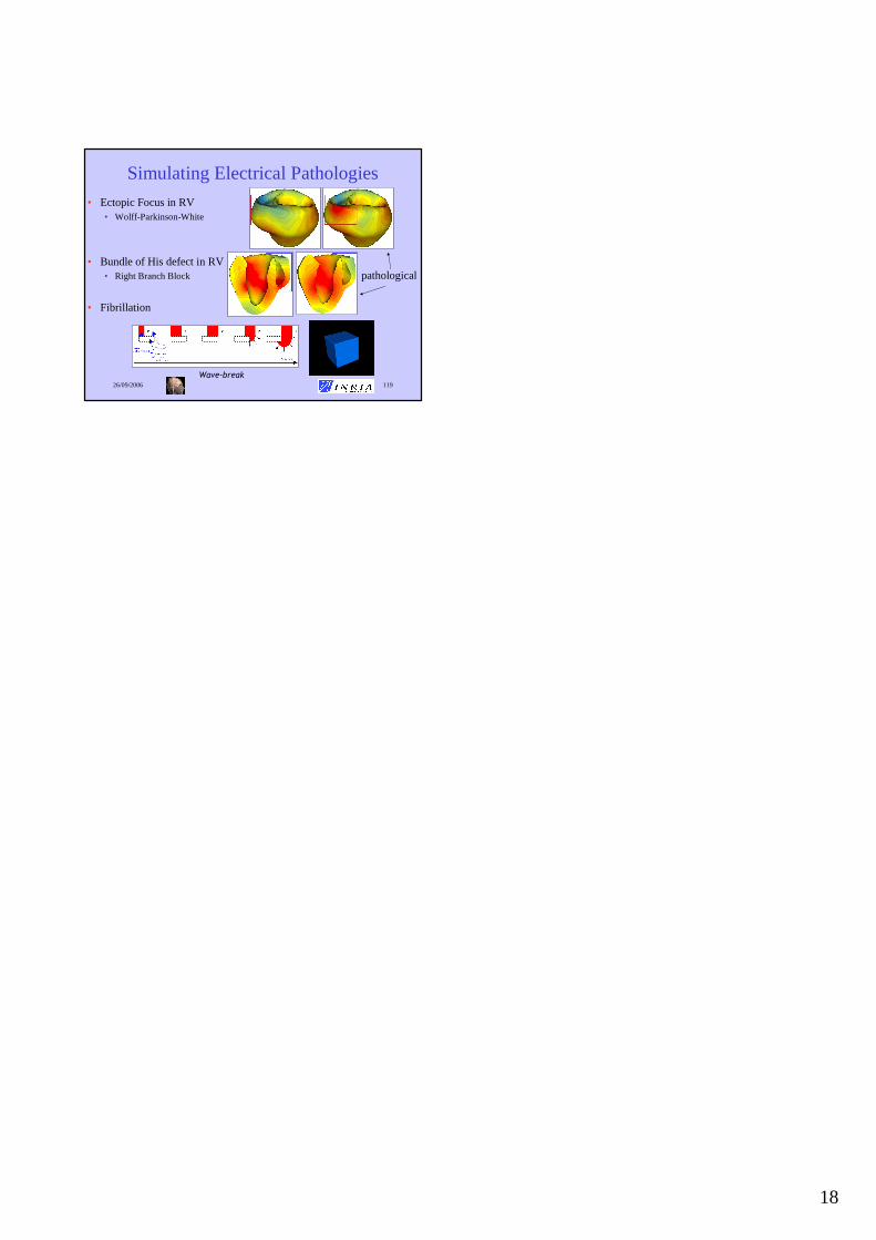
Simulating Electrical Pathologies
• Ectopic Focus in RV • Wolff-Parkinson-White
• Bundle of His defect in RV• Right Branch Block
• Fibrillation
Wave-break
pathological


