Download - Photovoltaic Emergencies

CA
L FI
RE –O
ffice
of t
he
Stat
e Fi
re M
arsh
al
Nov
emb
er 2
010
Fire OperatiOns FOr Photovoltaic Emergencies

CAL FIRE –Office of the State Fire Marshal November 2010
Fire OperatiOns FOr Photovoltaic Emergencies

Fire OperatiOns FOr Photovoltaic Emergencies
4 µµ
Fire OperatiOns FOr Photovoltaic Emergencies
Contents
TABLE OF CONTENTS ________________________________________________________ 4
Course Outline _____________________________________________________________ 9
SECTION 1: INTRODUCTION ___________________________________________________ 11
1.1 INTRODUCTION _________________________________________________________ 11
1.2 WHAT ARE PHOTOVOLTAICS? ____________________________________________ 12
1.3 STATE SAFETY REGULATIONS ____________________________________________ 13
1.4 NUMBER OF PV SYSTEMS IN CALIFORNIA___________________________________ 14
1.5 INCIDENT SUMMARY ___________________________________________________ 16
SECTION 2: PHOTOVOLTAIC CELLS AND COMPONENTS _____________________________ 19
2.1 INTRODUCTION _______________________________________________________ 19
2.2 ANATOMY OF A SOLAR CELL _____________________________________________ 21
2.3 PHOTOVOLTAIC MODULES ______________________________________________ 22
2.4 PHOTOVOLTAIC ARRAY _________________________________________________ 23
2.4 PHOTOVOLTAIC TILES AND SHINGLES _____________________________________ 24
2.5 RACK MOUNTED PHOTOVOLTAIC MODULES ________________________________ 24
2.6 INVERTERS ___________________________________________________________ 24
2.7 BATTERIES ___________________________________________________________ 25
SECTION 3: OPERATIONS AND TACTICS FOR PHOTOVOLTAIC SYSTEMS ________________ 27
3.1 INTRODUCTION _______________________________________________________ 27
3.2 RECOGNIZING PHOTOVOLTAIC SYSTEMS ___________________________________ 28
3.3. HAZARDS____________________________________________________________ 29
3.3.1 Electrical Hazards – Firefighter Electrical Safety! ___________________________ 29
3.3.2 Electric Shock and Burn Hazards ________________________________________ 29
3.3.3 Resistance to Electricity _______________________________________________ 30
3.3.4 Trip, Slip or Fall Hazards _______________________________________________ 31
3.3.5 Increased Dead Load Roof Loads ________________________________________ 31
3.3.6 HazMat – Firefighter Inhalation Hazards __________________________________ 31
3.3.7 Battery Hazards ______________________________________________________ 32
3.4. SIZE-UP _____________________________________________________________ 34

Fire OperatiOns FOr Photovoltaic Emergencies
5 µµ
Fire OperatiOns FOr Photovoltaic Emergencies
3.5 STRATEGY AND TACTICS ________________________________________________ 35
3.5.1 Strategy ____________________________________________________________ 35
3.5.2 Tactics ____________________________________________________________ 36
3.6 COMMUNICATIONS ____________________________________________________ 37
3.7 FIRE GROUND OPERATIONS _____________________________________________ 39
3.7.1 Roof Operations _____________________________________________________ 40
3.7.2 Ventilation Operations ________________________________________________ 43
3.7.3 Interior Operations ___________________________________________________ 43
3.7.4 Search Operations ___________________________________________________ 45
3.7.5 Overhaul ___________________________________________________________ 45
SECTION 4: RESIDENTIAL/SUBURBAN ___________________________________________ 47
4.1 INTRODUCTION _______________________________________________________ 47
STRATEGY AND TACTICS ___________________________________________________ 48
SECTION 5: COMMERCIAL LARGE AND SMALL ____________________________________ 51
5.1 INTRODUCTION _______________________________________________________ 51
5.2 STRATEGY AND TACTICS ________________________________________________ 52
SECTION 6: GROUND MOUNT AND RURAL SYSTEMS _______________________________ 55
6.1 INTRODUCTION _______________________________________________________ 55
6.3. HAZARDS____________________________________________________________ 56
6.4. SIZE-UP _____________________________________________________________ 57
6.5. STRATEGY AND TACTICS ________________________________________________ 58
6.5.1 Strategy ____________________________________________________________ 58
6.5.2 Tactics _____________________________________________________________ 58
SECTION 7: OFF-GRID SYSTEMS ________________________________________________ 61
7.1 INTRODUCTION _______________________________________________________ 61
SECTION 8: FUTURE SOLAR TECHNOLOGIES ______________________________________ 63
8.1 INTRODUCTION _______________________________________________________ 63
Appendix A: Review of Solar Thermal ___________________________________________ 66

Fire OperatiOns FOr Photovoltaic Emergencies
6 µµ
Fire OperatiOns FOr Photovoltaic Emergencies
MISSION StAtEMENt
The mission of State Fire Training is to enable the California fire service to safely protect life and property through education, training, and certification.
FIRE SERvICE tRAININg ANd EduCAtION PROgRAM
The Fire Service Training and Education Program (FSTEP), was established to provide specific train-ing needs of local fire agencies in California. State Fire Training coordinates the delivery of this training through the use of approved curricula and registered instructors.
The FSTEP series is designed to provide both the volunteer and career fire fighter with hands-on training in specialized areas such as fire fighting, extrication, rescue, and pump operations. All courses are deliv-ered through registered instructors and can be tailored by the instructor to meet your department’s specific need. Upon successful completion of an approved FSTEP course, participants will receive an Office of the State Fire Marshal course completion certificate.

Fire OperatiOns FOr Photovoltaic Emergencies
7 µµ
Fire OperatiOns FOr Photovoltaic Emergencies
Bill Brooks, Brooks Engineering
Steve Bunting, Newport Beach, F.D.
Frank Cercos, San Francisco F.D.
Denise Enea, Woodside F.P.D.
John Hostetter, REC Solar
Sue Kateley, CALSEIA
Wes Kitchel, Santa Rosa F.D.
Bill Tyler, Novato Fire District
Matt Paiss, San Jose Fire Department
Vickie Sakamoto, OSFM
We also thankfully acknowledge the following individual who served as a contributor to this document.
Mike French, B. P. Solar
ACkNOwLEdgMENtS
The development of this training program was made possible with funding from the California Fire Arson Training fund (CFAT). Before its publication, the Statewide Training and Education Advisory Committee (STEAC) recommended this guide for adoption by the State Fire Marshal. This guide is appropriate for fire service personnel and for personnel in related occupations.
Arnold Schwarzenegger, Governor
Lester A. Snow, Natural Resources Agency Secretary
Del Walters, CAL FIRE Director
Tonya Hoover, Acting State Fire Marshal
Michael Richwine, Chief, State Fire Training
Special acknowledgement and thanks are extended to the following members of State Fire Training for their diligent efforts and contributions that made the final publication of this document possible.
Mike Garcia, Deputy State Fire Marshal
Rodney Slaughter, Deputy State Fire Marshal
Tammara Askea, Graphic Design
The material contained in this document was compiled and organized through the cooperative effort of numerous professionals within, and associated with, the California fire service and the Photovoltaic industry. We gratefully acknowledge the following individuals who served as principal developers for this document.


Fire OperatiOns FOr Photovoltaic Emergencies
9 µµ
Course Outline
Course Objectives: At the conclusion of this class the student will…
a) Have a working knowledge of a Photovoltaic System
b) Be able to identify component parts of a Photovoltaic System
c) Identify and mitigate potential hazards
d) Identify occupancies and locations for Photovoltaic Systems
e) Perform size-up and develop response strategies and tactics
Course Content 8:00*
1. Introduction 0:30
2. Photovoltaic history, distribution and regulation 1:00
3. Photovoltaic components; modules, wiring and inverters 1:00
4. Photovoltaic operation and tactical considerations 2:00
5. Residential and suburban applications 1:00
6. Large and small commercial applications 1:00
7. Battery hazards for off-grid systems 1:00
8. Photovoltaic technologies underdevelopment 0:30
*Minimum course hours = 8. If the optional skills and evolutions are scheduled to be taught, adequate time and materials must be added.
REFERENCES
Callan, Michael, “Responding To Utility Emergencies: A Street Smart Approach to Un-derstanding and handling Electrical and Utility Gas Emergencies”, 1st Edition, Red Hat Publishing, 2004.
Grant, Casey, “Fire Fighter Safety and Emergency Response for Solar Power Systems,” NFPA, Fire Protection Research Foundation, Quincy MA, May 2010
Slaughter, Rodney, “Fundamentals of Photovoltaics for the Fire Service”, Dragonfly Communications Network, Corning, CA, September 2006.
U.S. Fire Administration, “Firefighter Fatalities in the United States in 1999,” National Fire Data Center, July 2000.


11 µµ
terminal Objective
At the conclusion of this module students will be able to recognize types of photovoltaic systems and components
Enabling Objective
The student will be able to:
• Describe a photovoltaic system
• Identify system components
1.1 INtROduCtION
With a variety of alternative electrical generation systems available, none is becoming more prevalent than those which convert solar energy to electricity. These systems are known as photovoltaic systems, or simply PV. A photovoltaic system consists of photovoltaic solar panels and other electrical components used to capture solar energy and convert it to electrical power. Many systems are roof mounted and may present hazards to firefighting operations. Firefighters can be sure that at some point in the future they will encounter an incident involving a building with a solar electric generating system.
PV systems are an economical and environmen-tally clean way to generate electricity and are here to stay. Your fundamental understanding of PV systems will increase your confidence when fight-ing fires involving PV equipment and when fight-ing fires in structures equipped with PV systems. The PV industry, utility companies, manufactur ers, suppliers, regulators, designers and installers are working with fire service to ensure that firefighters will be able to operate safely around PV systems.
The days of firefighters rushing in to a structure without first making an assessment and size-up of the emergency have passed. In addition to a several other hazards found in fighting fire in modern buildings, Fire fight ers must also be aware of PV systems and the associated hazards. The potential hazards, which will be discussed in this curriculum include, electrical shock, trip/slip/fall, increased roof loads, hazardous materials, and battery storage hazards. This training curriculum will review these dangers and hazards as well as make recommendations on how you can protect your fire crew members and yourself.
SECTION 1 | PHOTOVOLTAICS
12 µµ
The information contained in this curriculum is spe-cific to California. If used in other states or countries, some of the discussion should be updated to reflect local energy policies and regulations.
1.2 wHAt ARE PHOtOvOLtAICS?
“Photovoltaics” refers to the process of converting energy in the form of light from the sun to usable electrical current. A PV system refers to a system of components that, together, will generate electricity for use on site and may allow excess electricity to flow to the utility grid.
Since the 1980s, solar electricity has been used in many common household devices. You probably remember the early solar-powered calculators that didn’t need a battery and small solar charging sys-tems for recreational vehicles and boats. But this was just the beginning. The solar electric industry is now actively selling and installing PV systems throughout California. At the end of 2009, there were approximately 50,000 individual solar projects scattered throughout California on residential and commercial properties. Residential systems can create enough electricity to meet a home’s entire annual energy needs. There are also thousands of solar thermal systems in Califor-nia, which are used to provide hot water and home heating. This curriculum does not cover solar thermal water heating systems.
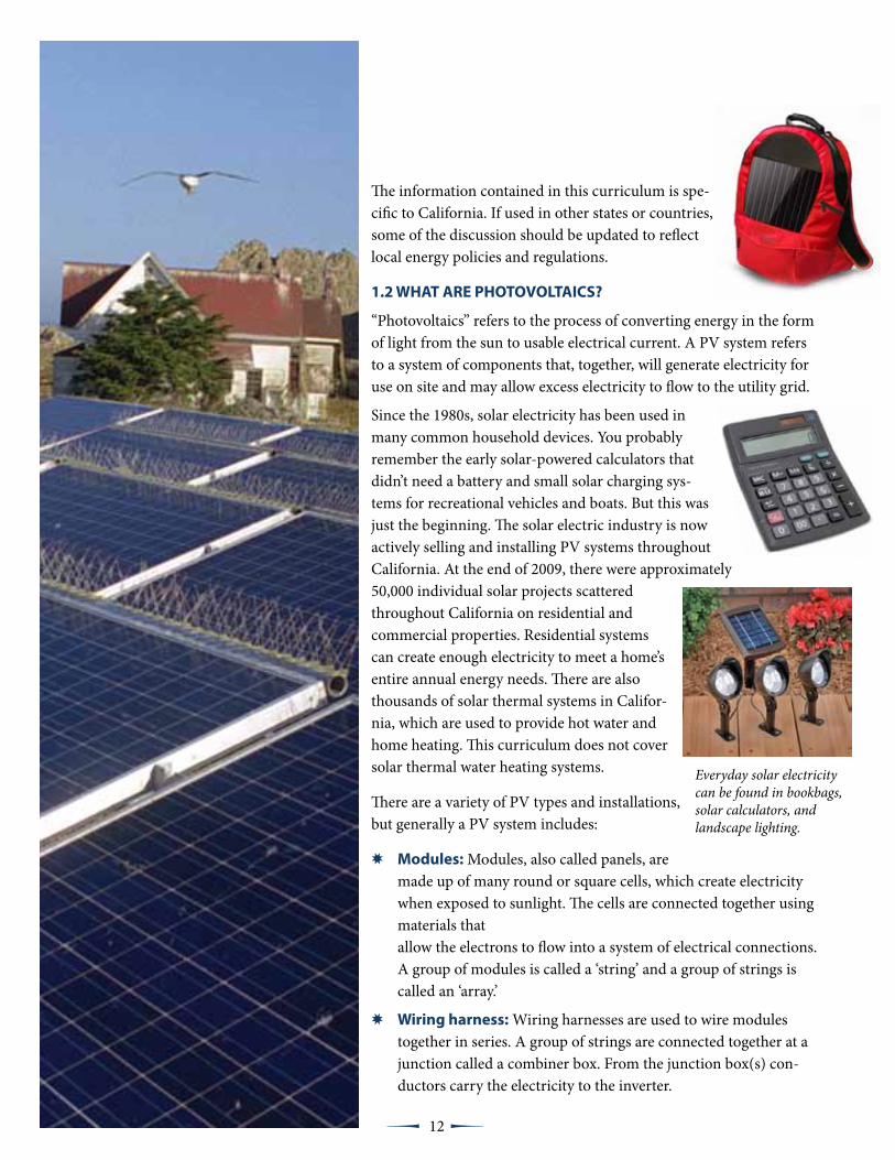
There are a variety of PV types and installations, but generally a PV system includes:
✸ Modules: Modules, also called panels, are made up of many round or square cells, which create electricity when exposed to sunlight. The cells are connected together using materials that allow the electrons to flow into a system of electrical connections. A group of modules is called a ‘string’ and a group of strings is called an ‘array.’
✸ wiring harness: Wiring harnesses are used to wire modules together in series. A group of strings are connected together at a junction called a combiner box. From the junction box(s) con-ductors carry the electricity to the inverter.
Everyday solar electricity can be found in bookbags, solar calculators, and landscape lighting.

Fire OperatiOns FOr Photovoltaic Emergencies
13 µµ
✸ Inverter: PV panels produce direct current which generally needs to be converted to alter-nating current. This is done by an inverter. The inverter is connected to the on-site utility service panel, so that electricity from the solar array can provide electricity to the site.
✸ Batteries: Batteries are used in “banks” store electricity.
✸ disconnect Switches: A PV system may have one or more disconnect switches between the arrays and the electrical service panel.
In other than off-grid systems, most PV systems installed today do not use batteries. Instead, the systems produce electricity for use on site or for transmission to the local utility. When more electricity is produced from the solar panels than is needed on site, the extra electricity is al- lowed to flow into the utility system. The surplus current runs through a meter that measures how much of electricity flows into the utility grid. The elimination of batteries has reduced the cost and increased the practicality of PV systems thereby allowing PV to be more available to consumers.
1.3 StAtE SAFEtY REguLAtIONS
Regulations in the National Electrical Code addressing solar electrical safety have been in place since the 1980s. As PV technology has evolved, so have the applicable codes and ordinances. Like all evolving technologies, practical experience plays an important role in the development of new regulations.
In 2007, the California Office of the State Fire Marshal (CAL FIRE) established a task force that included representatives from the fire service, building officials, other state agencies, and the PV industry in order to develop a guideline for the installation of PV systems. The Solar Photovol-taic Installation Guideline was developed to provide local jurisdictions and the solar industry with information for the layout, design, marking, and installation of solar photovoltaic systems. The Guideline can be located on-line at http://osfm.fire.ca.gov/training/photovoltaics.php and is intended to mitigate the fire and life safety issues. In addition, the Guideline provides labeling recommendations to help the fire service identify the components of the PV system at the scene of a fire. In May 2010, the International Code Council adopted a version of the California Guide-line into the 2012 International Fire Code.

Fire OperatiOns FOr Photovoltaic Emergencies
14 µµ
1.4 NuMBER OF Pv SYStEMS IN CALIFORNIA
Changes in PV technology, such as efficiency and availability have lowered the price of PV systems. As a result, the number of solar installations has increased dramatically. Figure 1 shows a chart of the number of solar projects in-stalled between 2001 and 2009 in the regions served by Pacific Gas & Electric (PG&E), Southern California Edison (SCE), and San Diego Gas & Electric (SDG&E). Table 1 shows the actual numbers in these same utility areas.
Figure 1: Number of solar projects in California, 2001-2009
Table 1: Number of PV Projects by Utility Area
utility Area
thru 2001 2002 2003 2004 2005 2006 2007 2008 2009
SCE 294 446 801 939 807 1344 1873 2352 2769SDG&E 306 350 537 861 934 961 1028 951 1658PG&E 745 1243 1856 3104 2824 4348 6578 6547 6607Total 1345 2039 3194 4904 4565 6653 9479 9850 11034
Even though incentives are available statewide, most PV projects are installed in areas where electricity use and rates are high. Typically, these are areas in which the use of air conditioning is highest. Utilities in California use a tiered billing system; the rate paid for electricity by the consumer is higher based upon the quantity of electricity used. How-ever, some customers choose to install PV systems simply out of concern for the environment or climate change.
12000
10000
8000
6000
4000
2000
0
thru 2002 2003 2004 2005 2006 2007 2008 20092001
PG&E
SDG&E
SCE
15 µµ
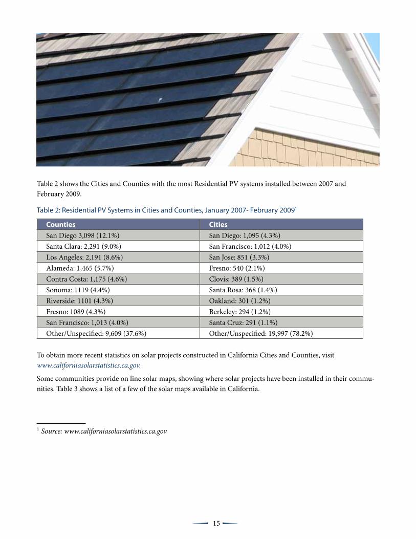
Table 2 shows the Cities and Counties with the most Residential PV systems installed between 2007 and February 2009.
Table 2: Residential PV Systems in Cities and Counties, January 2007- February 20091
Counties Cities
San Diego 3,098 (12.1%) San Diego: 1,095 (4.3%)Santa Clara: 2,291 (9.0%) San Francisco: 1,012 (4.0%)Los Angeles: 2,191 (8.6%) San Jose: 851 (3.3%)Alameda: 1,465 (5.7%) Fresno: 540 (2.1%)Contra Costa: 1,175 (4.6%) Clovis: 389 (1.5%)Sonoma: 1119 (4.4%) Santa Rosa: 368 (1.4%)Riverside: 1101 (4.3%) Oakland: 301 (1.2%)Fresno: 1089 (4.3%) Berkeley: 294 (1.2%)San Francisco: 1,013 (4.0%) Santa Cruz: 291 (1.1%)Other/Unspecified: 9,609 (37.6%) Other/Unspecified: 19,997 (78.2%)
To obtain more recent statistics on solar projects constructed in California Cities and Counties, visit www.californiasolarstatistics.ca.gov.
Some communities provide on line solar maps, showing where solar projects have been installed in their commu-nities. Table 3 shows a list of a few of the solar maps available in California.
1 Source: www.californiasolarstatistics.ca.gov

Fire OperatiOns FOr Photovoltaic Emergencies
16 µµ
Table 3: Solar Map Websites
City web site
San Francisco http://sf.solarmap.org/Los Angeles http://solarmap.lacounty.gov/San Diego http://sd.solarmap.org/solar/index.phpBerkeley http://berkeley.solarmap.org/solarmap_v4.htmlSacramento http://smud.solarmap.org/map.htmlSan Jose http://www.sanjoseca.gov/esd/energy/svenergymap.asp
1.5 INCIdENt SuMMARY
As the number of PV systems has increased, fire service experience with theses systems has also grown. In addition, the fire service has experienced several fires involving buildings equipped with PV and fires involving the PV components. These experiences have not resulted in death or serious injury to firefighters but they have high-lighted the need for the solar industry to work with the fire service.
Table 3 shows a brief summary of incidents that have been re-ported. Lessons learned from these incidents will be used in case studies and examples in this training material.
Table 4: Incident Summary
date Location Summary
June 1996 Grassy Area Small grass fire originating from PV modules.
2003San Bernardino (De-vore, CA)
Residential wildfire in the region. Building and PV system survived (all other buildings destroyed)
2004 Strip Mall Overheated junction box with smoke and no fire.
Feb 2008 Long Beach, CA
Convention center fire on two modules. The modules involved were field repaired by the manufacturer representative. Damage limited to the modules.
June 2008 Sedona AZ
Residential content fire. PV system was destroyed. Firefighter re-ceived an electric shock (non life threatening) that was first attribut-ed to the PV system but later attributed to the utility power supply.
May 2008 San Francisco, CAUniversity of San Francisco fire started at the array and extinguished by maintenance personnel.
Jan 2009 Torrance, CA
Residential fire started at PV modules 2 weeks after the system was installed. The modules were ‘do-it-yourself ’ of questionable installa-tion quality.
A content fire in the garage of this residence destroyed the PV inverter box.

Fire OperatiOns FOr Photovoltaic Emergencies
17 µµ
June 2009 Concord, CA
Concord CA- Residential Garage fire. PV system not involved and did not burn (although inverter was destroyed because of the extent of the fire. The PV system did not cause the fire.
Mar 2009 Simi Valley, CAResidential fire started in a shingle module of an integrated roof PV system.
Apr 2009 Bakersfield, CABig Box retail store fire may have started in the PV conduit or the array.
Summer 2009 San Francisco, CA
Convention Center incident. PV Modules observed arcing. No fire occurred. Modules replaced.
Summer 2009 Davis, CA Grass fire at PV USA a former PV research center.
June 2009 Bursdadt, GermanyLarge warehouse. Fire occurred at the PV modules (200 square feet of a 5 MW system) within the array.
Jan 2010 MinnesotaA chimney fire that was originally attributed to nearby roof-mount-ed air heating panels but later corrected.
Mar 2010 Victorville, CA
Concentrating modules burned while stored on site before instal-lation took place. Fire likely caused by a cigarette or other burning material that came in contact with the boxes where the modules were stored.
Apr 2010 Maryland
Residential fire—Older PV system. Fire started at modules. Reports are debris beneath modules may have been involved in the cause of the fire.
Apr 2010 San Diego, CA
Residential fire on an 8 year old, self-installed PV system, started at the inverter. PV modules not involved. The lack of an external DC disconnect, prevented resident and emergency responders from turning off power from the modules.
May 2010 FresnoA Fresno College campus a fire occurred in the combiner box of a PV system, mounted on a parking structure.

Fire OperatiOns FOr Photovoltaic Emergencies
18 µµ
This brief summary of PV incidents chronicles a range of issues that are associated with PV. But this review reveals that some of these problems did not start with the PV system, but from inexperienced installations, installations using damaged panels, and incidents that occurred before the PV system was actually installed. Importantly, some of these incidents started as a result of overheated arrays and junction boxes. While some PV systems were involved with a structural fire, they were not the origin of the fire. In all cases, developing a fundamental un-derstanding of PV systems will help you stay safe when operating around the system and help you mitigate potential emergencies.
Each cell of a PV module is wired together to the junction box on the back side of the module. The picture, lower left, shows the damage to the junction box after it becomes overheated.

19 µµ
terminal Objective
At the conclusion of this module students will have knowledge of the basic parts of a PV system.
Enabling Objective
The student will be able to:
• Describe the basic parts of a PV panel
• Identify system components
• Understand basic design considerations
2.1 INtROduCtION
Photovoltaics begin at the source—the Sun! Every day enough solar energy falls on the earth to sup ply all the world’s energy needs for four to five years. The Sun’s full intensity and bright ness, often called “peak sun”, is 1,000 watts per square meter (referred to as irradiance). This inten sity can be diminished by the micro climate and site specific con ditions, such as weather and shade. But even on overcast days caused by smog or
clouds, solar electricity can still be generated by the solar panels, although at significantly reduced efficiency.
The sun produces the most energy between 9 am and 3 pm. To maximize their efficiency, most PV systems in the Northern Hemisphere are
orientated toward the south. Understanding how solar cells gener ate electricity is one thing. Under standing what to do with all that elec-
tricity is another. In many cases, a PV system will generate more electric ity during the sunniest part of the day than can be used at
the time.
The main point that a firefighter needs to have about PV electrical generation is that the amount of current generated depends on how intense the sunlight is. If the
sunlight doubles in intensity, the current generated by the array will also double.
The current is not unlimited as with energy supplied by a utility service. For a utility service, a short circuit can generate 10,000 amps at a residence to 100,000 amps at a large commercial facility. These high short-circuit currents at utility services are a severe hazard to the firefighter. PV systems, on the other hand, are limited by the presence of sunlight. A large residential PV system might have 30 amps of short circuit current at full sun (compared to the 10,000 amps of utility supplied current), and a large commercial PV array may have 1,500 amps of available short circuit current
SECTION 2: PHOTOVOLTAIC CELLS AND COMPONENTS
Azimuth at Sunset
North
South
Azimuth at Sunrise
56 degrees
122 degrees
June 21Sun Path
December 21Sun Path

Fire OperatiOns FOr Photovoltaic Emergencies
20 µµ
(compared to the 100,000 amps of utility sup-plied current). What this means for firefight-ers is that there is a significant difference in the hazard for arc flashes and arc burns between utility supplied current versus PV generated current. However, it does not mean that the PV electrical power is completely safe. It still poses many of the electrocution hazards that are discussed in this training.
Another important consideration for firefighters is that the voltage is very consistent during daylight hours. As soon as the sky is light and it is possible to easily see outdoors without artifi-cial light, the voltage on a PV array will rise to the voltage it will operate at throughout the day.
Although current (amperage) is what causes damage to a person’s body, the voltage is what drives that current through the body. The higher the voltage, the higher the amount of current is forced through the body in an electrical shock. The simple rule is that if it is possible to see outdoors eas-ily without the need for artificial light, then the PV array is generating dangerous voltage.
0
100
200
300
400
500
600
0 100 200 300 400 500 600 700 800 900 1000 1100
Volts
Sunlight Intensity (Wa3s/m2)
Array Voltage vs. Sunlight Intensity
Sunrise
Noon
0
1
2
3
4
5
6
7
8
9
10
0 100 200 300 400 500 600 700 800 900 1000 1100
Amps
Sunlight Intensity (Wa4s/m2)
Array Current vs. Sunlight Intensity
Sunrise
Noon
Fire OperatiOns FOr Photovoltaic Emergencies
21 µµ
Pho tovoltaic designers have several options in regard to the fluctuation of energy throughout the day:
✸ Store excess electricity in a bank of batteries so that the electric ity can be used when the sun is not shining. This design is typical of an off-grid system.
✸ Credit excess electricity generated back to the utility company. This is typical of a grid-tied system.
✸ Store electricity in the battery bank and credit excess electricity back to the utility grid. This battery back-up system ensures that the building owner will have enough electricity stored in case of a utility grid power outage (While battery back-up systems do exist, they are not common in the urban setting).
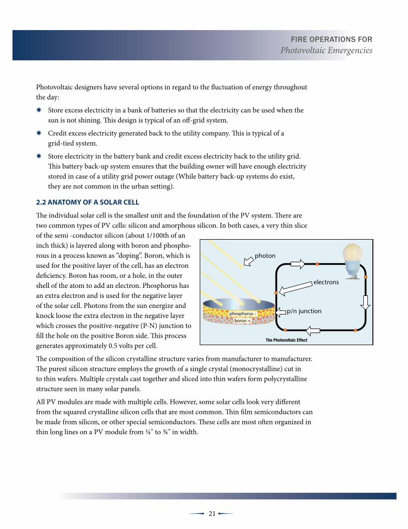
2.2 ANAtOMY OF A SOLAR CELL
The individual solar cell is the smallest unit and the foundation of the PV system. There are two common types of PV cells: silicon and amorphous silicon. In both cases, a very thin slice of the semi -conductor silicon (about 1/100th of an inch thick) is layered along with boron and phospho-rous in a process known as “doping”. Boron, which is used for the positive layer of the cell, has an electron deficiency. Boron has room, or a hole, in the outer shell of the atom to add an electron. Phosphorus has an extra electron and is used for the nega tive layer of the solar cell. Photons from the sun energize and knock loose the extra electron in the negative layer which crosses the positive-negative (P-N) junction to fill the hole on the positive Boron side. This process generates approximately 0.5 volts per cell.
The composition of the silicon crystalline structure varies from manufacturer to manufacturer. The purest silicon structure employs the growth of a single crystal (monocrystalline) cut in to thin wafers. Multiple crystals cast together and sliced into thin wafers form polycrystalline structure seen in many solar panels.
All PV modules are made with multiple cells. However, some solar cells look very different from the squared crystalline silicon cells that are most common. Thin film semiconductors can be made from silicon, or other special semiconductors. These cells are most often organized in thin long lines on a PV module from ¼" to ¾" in width.
photon
electrons
p/n junction
�����������������������
phosphorus -
boron +
Fire OperatiOns FOr Photovoltaic Emergencies
22 µµ
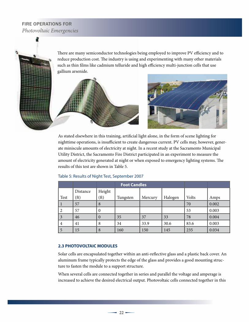
There are many semiconductor technologies being employed to improve PV efficiency and to reduce production cost. The industry is using and experimenting with many other materials such as thin films like cadmium telluride and high efficiency multi-junction cells that use gallium arsenide.
As stated elsewhere in this training, artificial light alone, in the form of scene lighting for nighttime operations, is insufficient to create dangerous current. PV cells may, however, gener-ate miniscule amounts of electricity at night. In a recent study at the Sacramento Municipal Utility District, the Sacramento Fire District participated in an experiment to measure the amount of electricity generated at night or when exposed to emergency lighting systems. The results of this test are shown in Table 5.
Table 5: Results of Night Test, September 2007
Foot Candles
TestDistance (ft)
Height (ft) Tungsten Mercury Halogen Volts Amps
1 57 8 70 0.0022 57 0 53 0.0033 46 0 35 37 33 78 0.0044 41 8 34 33.9 30.6 83.6 0.0035 15 8 160 150 145 235 0.034
2.3 PHOtOvOLtAIC MOduLES
Solar cells are encapsulated together within an anti-reflective glass and a plastic back cover. An aluminum frame typically protects the edge of the glass and provides a good mounting struc-ture to fasten the module to a support structure.
When several cells are connected together in series and parallel the voltage and amperage is increased to achieve the desired electrical output. Photovoltaic cells connected together in this

Fire OperatiOns FOr Photovoltaic Emergencies
23 µµ
manner form a PV module. Weather-proof electrical connections are mounted on the back of the module for quick connections to other modules that comprise the PV array.
Modules come in a variety of sizes and rated outputs. A standard size module is approximately 5 feet by 3 feet, produces 20 to 40-volts, and consists of 50 to 72 solar cells. An average size crystalline module weighs between 30 and 50 pounds, most of which is the weight of the glass.
PV panels have no moving parts. An owner may need to occasionally wash dust, dirt, and bird droppings off the panels to keep them operating at peak efficiency. The panels themselves are com-pletely weather proof, so there is little danger to those who perform this maintenance function.
2.4 PHOtOvOLtAIC ARRAY
One or more strings of modules forms an array. The modules are wired together in series to in-crease voltage, like the batteries in your flashlight. The strings are then wired together in parallel to increase amperage. Residential systems with outputs of 600 volts are common. The average house-hold in California uses about 6,500 kilo watt-hours per year. A PV system in the three-to four-kilowatt range should adequately meet most residential electrical needs. A 20 module array, capable of generating over 4,000 watts, will weigh approxi mately 900 to 1,050 pounds. The weight of the system will be equally distributed over approximately 420 square feet of the roof, resulting in an increase to the roof weight load of approximately 2.5 pounds per square foot.
�����������������
���������������������������������
�������
�������
�������
�������
Fire OperatiOns FOr Photovoltaic Emergencies
24 µµ
2.4 PHOtOvOLtAIC tILES ANd SHINgLES
Some residential PV systems are designed to be installed integrally with the roof tiles or shingles. These PV tiles or shingles become part of the roof system. This type of PV sys tem is a form of “building-in-tegrated” design. PV roof tiles match the depth of cement or clay tile roofs, and PV shingles do the same with composition shingles.
For building owners living in certain fire hazard severity zones, roof-ing systems must meet the Cali fornia Building Code (CBC) for Class A roofing materials. PV tiles or shingles would also have to comply with this regulation. Some manufacturers of PV roofing tiles have a Class A rating.
2.5 RACk MOuNtEd PHOtOvOLtAIC MOduLES
The most common installation of PV systems is to fasten the mod-ules to racks that are mounted above the existing roof surface. This method of installation is useful to ensure that the modules are oriented properly toward the sun and properly anchored to the roof. In fire hazard severity zones, PV modules that are mounted on racks above the roof covering do not have to meet the CBC Class A roofing requirement as long as the underlying roof is Class A.
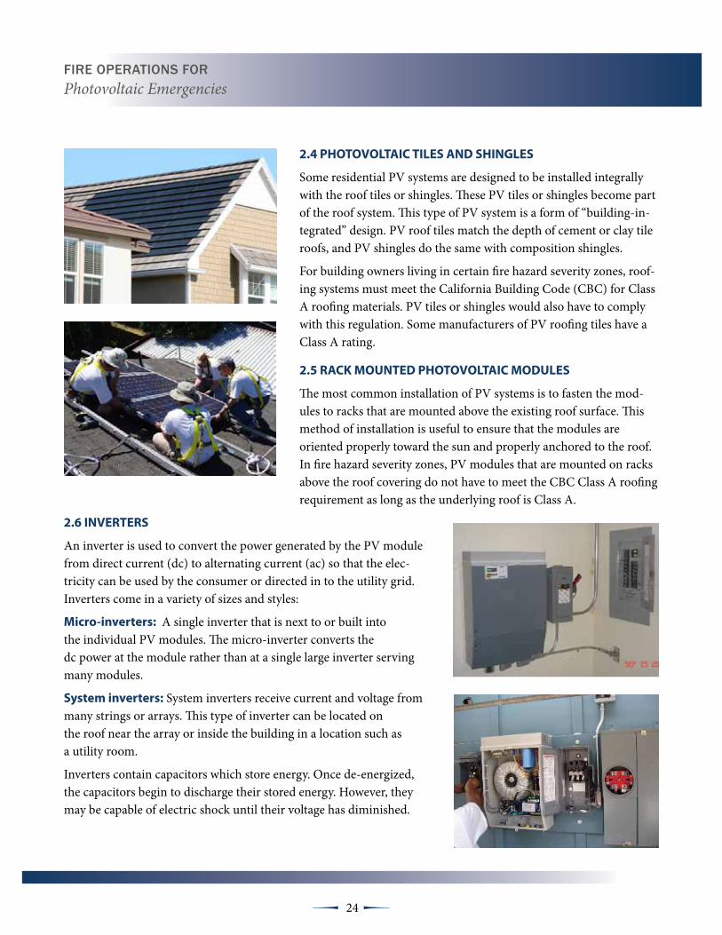
2.6 INvERtERS
An inverter is used to convert the power generated by the PV module from direct current (dc) to alternating current (ac) so that the elec-tricity can be used by the consumer or directed in to the utility grid. Inverters come in a variety of sizes and styles:
Micro-inverters: A single inverter that is next to or built into the individual PV modules. The micro-inverter converts the dc power at the module rather than at a single large inverter serving many modules.
System inverters: System inverters receive current and voltage from many strings or arrays. This type of inverter can be located on the roof near the array or inside the building in a location such as a utility room.
Inverters contain capacitors which store energy. Once de-energized, the capacitors begin to discharge their stored energy. However, they may be capable of electric shock until their voltage has diminished.
Fire OperatiOns FOr Photovoltaic Emergencies
25 µµ
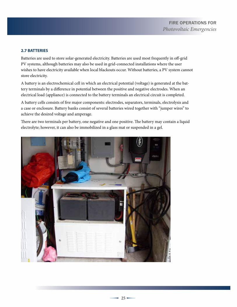
2.7 BAttERIES
Batteries are used to store solar-generated electricity. Batteries are used most frequently in off-grid PV systems, although batteries may also be used in grid-connected installations where the user wishes to have electricity available when local blackouts occur. Without batteries, a PV system cannot store electricity.
A battery is an electrochemical cell in which an electrical potential (voltage) is generated at the bat-tery terminals by a difference in potential between the posi tive and negative electrodes. When an electrical load (appliance) is connected to the battery terminals an electrical circuit is completed.
A battery cells consists of five major components: elec trodes, separators, terminals, electrolysis and a case or enclosure. Battery banks consist of several batteries wired together with “jumper wires” to achieve the desired voltage and amperage.
There are two terminals per battery, one negative and one positive. The battery may contain a liquid electrolyte; however, it can also be immobilized in a glass mat or suspended in a gel.


27 µµ
terminal Objective
At the conclusion of this module students will be understand hazards and related factors necessary for operations involved in emergency response.
Enabling Objective
The student will be able to:
• Recognize PV systems
• Identify system locations
• Identify hazards with PV systems
• Perform size up
• Have knowledge of strategies and tactics
SECTION 3: OPERATIONS AND TACTICS FOR PHOTOVOLTAIC SYSTEMS
Firefighters need to practice and train for roof operations and ventilation techniques when photovoltaic systems are present.
3.1 INtROduCtION
Fire Department response, to buildings equipped with PV systems, has become more and more frequent. The increase in response to incidents involving PV is not because the systems are unsafe or hazardous in general, but because improved technology and lower cost and has made these systems a common addition to both new and existing buildings. Owners of residential, commercial and industrial occupancies see these systems as a source of “green” energy available at a greatly reduced rate when compared to the increasing cost of energy provided by public and private utility companies.
Many firefighters view PV systems as a hazard because they’re located on or near buildings and they generate electricity. As with any new technology we as firefighters encounter, the more knowl-edge firefighters have the more successful they will be in develop-ing a successful tactics and strategies when operating at incidents involving PV systems.
Operating at incidents where PV systems are present may require firefighters to adjust their actions somewhat; however these adjustments should be similar to those that are necessary with many other types of electrical equipment or power generating sources.
If firefighters are able to identify the presence of PV systems and understand the hazards associated with the technology, they can then adjust their operations to mitigate the situation in the safest and most effective manner.
Fire OperatiOns FOr Photovoltaic Emergencies
28 µµ
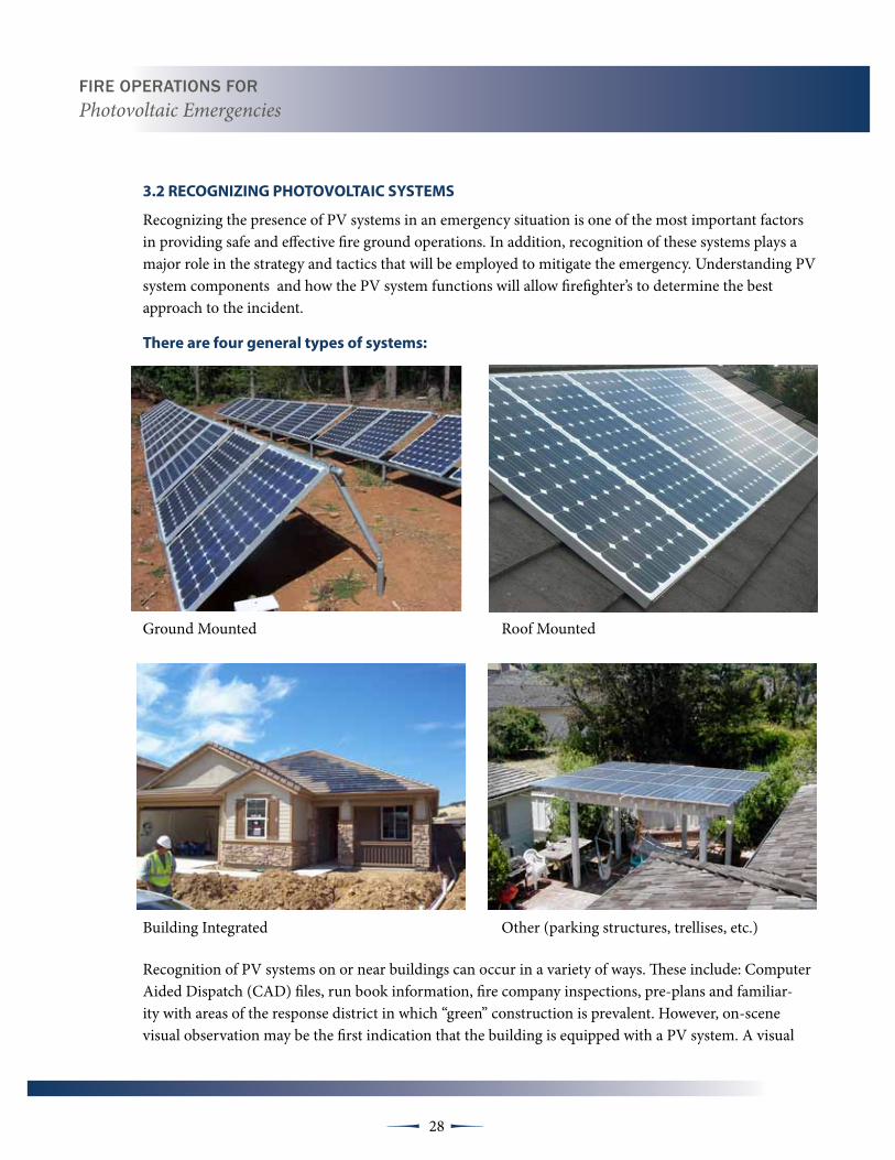
3.2 RECOgNIZINg PHOtOvOLtAIC SYStEMS
Recognizing the presence of PV systems in an emergency situation is one of the most important factors in providing safe and effective fire ground operations. In addition, recognition of these systems plays a major role in the strategy and tactics that will be employed to mitigate the emergency. Understanding PV system components and how the PV system functions will allow firefighter’s to determine the best approach to the incident.
there are four general types of systems:
Ground Mounted Roof Mounted
Building Integrated Other (parking structures, trellises, etc.)
Recognition of PV systems on or near buildings can occur in a variety of ways. These include: Computer Aided Dispatch (CAD) files, run book information, fire company inspections, pre-plans and familiar-ity with areas of the response district in which “green” construction is prevalent. However, on-scene visual observation may be the first indication that the building is equipped with a PV system. A visual
29 µµ
observation may not always be counted on because often PV systems cannot be seen from the street side or from ground level. Additionally, built-in PV and even roof mounted systems may be difficult or impossible to see at night.
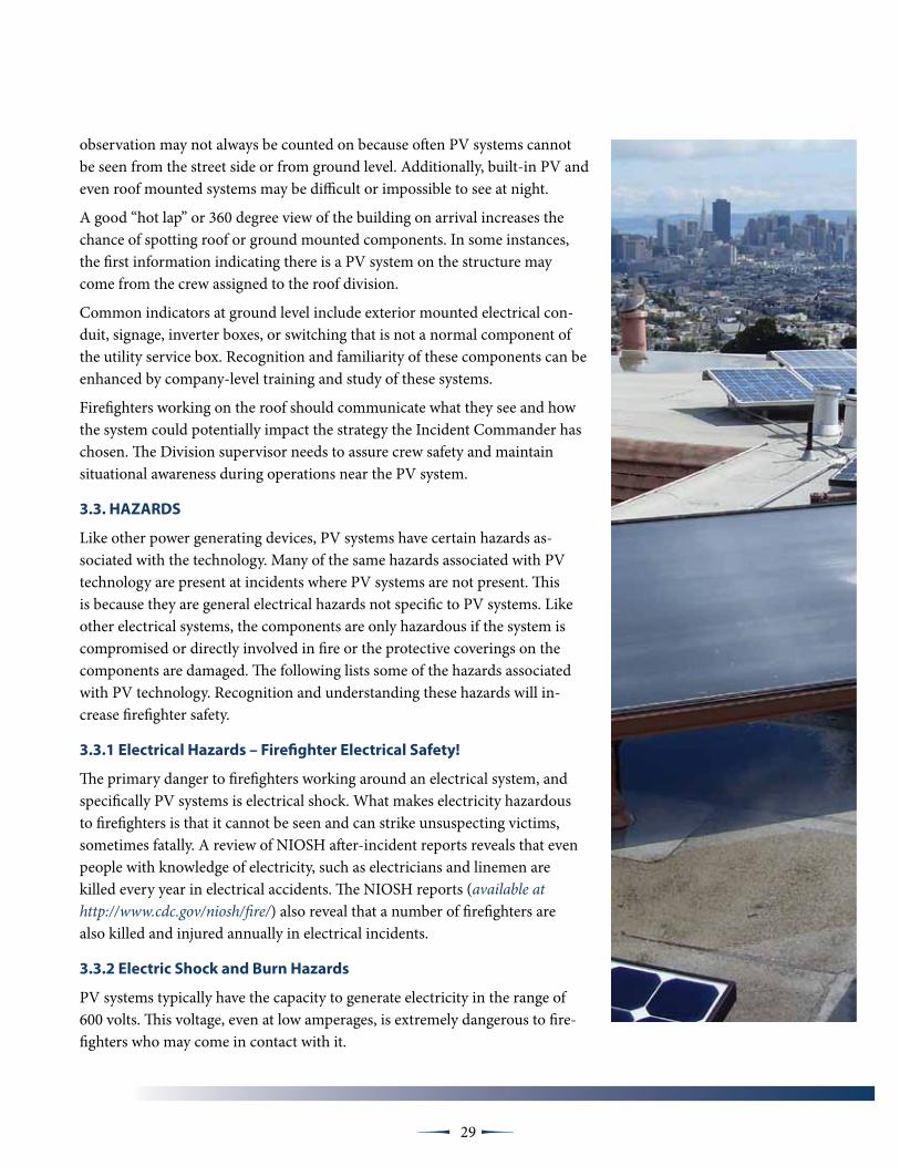
A good “hot lap” or 360 degree view of the building on arrival increases the chance of spotting roof or ground mounted components. In some instances, the first information indicating there is a PV system on the structure may come from the crew assigned to the roof division.
Common indicators at ground level include exterior mounted electrical con-duit, signage, inverter boxes, or switching that is not a normal component of the utility service box. Recognition and familiarity of these components can be enhanced by company-level training and study of these systems.
Firefighters working on the roof should communicate what they see and how the system could potentially impact the strategy the Incident Commander has chosen. The Division supervisor needs to assure crew safety and maintain situational awareness during operations near the PV system.
3.3. HAZARdS
Like other power generating devices, PV systems have certain hazards as-sociated with the technology. Many of the same hazards associated with PV technology are present at incidents where PV systems are not present. This is because they are general electrical hazards not specific to PV systems. Like other electrical systems, the components are only hazardous if the system is compromised or directly involved in fire or the protective coverings on the components are damaged. The following lists some of the hazards associated with PV technology. Recognition and understanding these hazards will in-crease firefighter safety.
3.3.1 Electrical Hazards – Firefighter Electrical Safety!
The primary danger to firefighters working around an electrical system, and specifically PV systems is electrical shock. What makes electricity hazardous to firefighters is that it cannot be seen and can strike unsus pecting victims, sometimes fatally. A review of NIOSH after-incident reports reveals that even people with knowledge of electricity, such as electricians and linemen are killed every year in electrical accidents. The NIOSH reports (available at http://www.cdc.gov/niosh/fire/) also reveal that a number of firefighters are also killed and injured annually in electrical incidents.
3.3.2 Electric Shock and Burn Hazards
PV systems typically have the capacity to generate electricity in the range of 600 volts. This voltage, even at low amperages, is extremely dangerous to fire-fighters who may come in contact with it.
Fire OperatiOns FOr Photovoltaic Emergencies
30 µµ
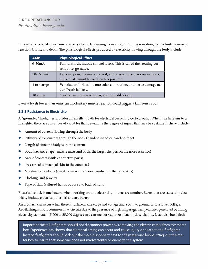
In general, electricity can cause a variety of effects, ranging from a slight tingling sensation, to involuntary muscle reac tion, burns, and death. The physiological effects pro duced by electricity flowing through the body include:
AMP Physiological Effect
6-30mA Painful shock, muscle control is lost. This is called the freezing cur-rent or let go range.
50-150mA Extreme pain, respiratory arrest, and severe muscular contractions, individual cannot let go. Death is possible.
1 to 4 amps Ventricular fibrillation, muscular contraction, and nerve damage oc-cur. Death is likely.
10 amps Cardiac arrest, severe burns, and probable death.
Even at levels lower than 6mA, an involuntary muscle reaction could trigger a fall from a roof.
3.3.3 Resistance to Electricity
A “grounded” firefighter provides an excellent path for electrical current to go to ground. When this happens to a firefighter there are a number of variables that determine the degree of injury that may be sustained. These include:
✸ Amount of current flowing through the body
✸ Pathway of the current through the body (hand-to-hand or hand-to-foot)
✸ Length of time the body is in the current
✸ Body size and shape (muscle mass and body, the larger the person the more resistive)
✸ Area of contact (with conductive parts)
✸ Pressure of contact (of skin to the contacts)
✸ Moisture of contacts (sweaty skin will be more conduc tive than dry skin)
✸ Clothing and Jewelry
✸ Type of skin (callused hands opposed to back of hand)
Electrical shock is one hazard when working around electricity—burns are another. Burns that are caused by elec-tricity include electrical, thermal and arc burns.
An arc-flash can occur when there is sufficient amperage and voltage and a path to ground or to a lower voltage. Arc-flashing is most common in ac circuits due to the presence of high amperage. Temperatures generated by arcing electricity can reach 15,000 to 35,000 degrees and can melt or vaporize metal in close vicinity. It can also burn flesh
Important Note: Firefighters should not disconnect power by removing the electric meter from the meter box. Experience has shown that electrical arcing can occur and cause injury or death to the firefighter. Instead firefighters should lock out the main disconnect next to the meter and lock out/tag-out the me-ter box to insure that someone does not inadvertently re-energize the system

Fire OperatiOns FOr Photovoltaic Emergencies
31 µµ
and ignite clothing at distances of up to 10 feet. The best way to prevent arc-flash hazards is to de-energize electri-cal equipment and circuits before approaching or touching electrical equipment.
3.3.4 trip, Slip or Fall Hazards
PV systems are comprised of metal, glass, conduit and cable, all of which are slippery when wet. Some of these components protrude above the roof line or crisscross the space between rows of modules and may not be visible to firefighters in dark or smoky conditions creating a trip and fall hazard. Building integrated components, such as roof tile or shingle shaped PV modules may not be visible at all to a firefighter walking across a roof at night.
Important Note: While you already know to avoid trip hazards posed by vent stacks, skylights and other obstacles on the roof, you now need to also consider walking and working around the pho-tovoltaic array and in as many cases solar water heating and swim-ming pool heating collectors.
3.3.5 Increased dead Load Roof Loads
A PV system installed during new construction or retro-fitted onto an existing building adds weight to the roof assembly. Light-weight constructed roofs are engineered to carry the building’s design load under normal condi-tions. They are not designed to continue to support a load under fire conditions. The additional weight of a PV system, whether part of the original design load, or added as a retrofit, is likely to cause a roof to fail sooner.
3.3.6 HazMat—Firefighter Inhalation Hazards
Many hazardous materials used in the semi-conductor indus-try are also used in the construction of PV modules. These include: silicon, boron, phosphorus, cadmium, tellurium, arsenic, and gallium. Under normal conditions, these materi-als are sandwiched and sealed between a layer of glass and a plastic backing all of which are encased in an aluminum frame. During a fire involving PV modules the aluminum frame can easily deform or melt, exposing these materials to direct flame. The hazardous materials then become dissi-pated in the smoke plume and may be inhaled by firefighters not wearing breathing apparatus. Firefighters should also take caution when performing overhaul on and around PV

Fire OperatiOns FOr Photovoltaic Emergencies
32 µµ
modules and other electric components and continue to wear respiratory protection until the scene has been cleared by safety or hazardous material personal.
3.3.7 Battery Hazards
In some PV systems, batteries are used to store solar-generated electricity. Batteries are used most frequently in off-grid PV systems, although batteries are also used in grid-tied applications where the user wishes to have elec-tricity available in the event of a power failure. Without batteries, a PV system cannot store elec tricity. Typically, several batteries will be arranged to form a “battery bank”. The batteries in the bank are connected to each other with “jumper wires” to either increase voltage, or to increase amperage. The most commonly used batteries are lead acid. Lead acid batteries contain sulfuric acid that can cause harmful and explosive fumes. Once it has been determined that a building has a bank or banks of batteries, the IC and all personnel operating around the batteries should be notified.
Recommended Practice
The inhalation hazards from the chemicals inherent in PV modules engulfed in a fire or explosion can be mitigated as long as firefighters wear their SCBA’s and personal protective equipment during a structural firefighting and overhaul operations. It is the decision of the Incident Commander whether or not the emergency consti tutes sheltering the population “in-place” downwind of the emergency. Fire or explo-sion emergencies involv ing large number of PV arrays, as in a commercial application, may necessitate evacuating downwind of the emergency.

Fire OperatiOns FOr Photovoltaic Emergencies
33 µµ
During normal charging operations, batteries emit both hydrogen and hydrogen sulfide gas. Both of these gases are highly flammable. Hydrogen is lighter than air and hydrogen sulfide is slightly heavier. For this reason, spark producing equipment and open flames are not allowed where batteries are used or stored. Firefighters operating in and around battery storage areas should only use flashlights and other equipment approved for CLASS 1 atmospheres.
Another type of battery that is in use for PV systems is the Lithium ion battery. Lithium ion batteries are more efficient than lead acid batter-ies and therefore can take up less space. Lithium ion batteries contain flammable liquid electrolyte that may vent, ignite and produce sparks when subjected to high temperatures, damaged or abused (e.g., mechanical damage or electrical overcharg-ing). Lithium ion batteries may burn rapidly with flare-burning effect and may ignite other batteries or combustibles in close proximity. Contact with the electrolyte in the lithium ion battery may be irritating to skin, eyes and mu-cous membranes. Fire will produce irritating, corrosive and/or toxic gases including hydrogen fluoride gas. PV modules themselves have no storage capacity. Inverters have capacitors which do store energy; however, the energy within the capaci-tors is discharged soon after power to the inverters is disconnected.
Important Note
Never cut into batteries under any circumstances! Even though the voltage generating PV system may be disconnected from the battery bank, the batteries themselves still have potential for electrical shock. If the battery is punctured by a conductive object, assume that the object may be charged.
Inverters have capacitors that store energy which is discharged soon after power to the inverters is disconnected.
Fire OperatiOns FOr Photovoltaic Emergencies
34 µµ
3.4. SIZE-uP
Every firefighter is familiar with the term size-up. A good size-up is critical to starting the incident down the appro-priate path to a successful conclusion. In the case of PV systems, it is extremely helpful to be aware of the presence of these systems prior to an incident. The reason for this is quite simple; the presence of these systems could possibly cause a change to strategy and tactics.
Firefighters should be aware of PV systems in their re-sponse district. Information about systems can be collected from a variety of sources:
✸ Company Pre-Incident Surveys and Prevention Inspections
✸ Fire Prevention Bureau records
✸ Building and Planning Department responsible for issuing the installation permit
✸ Visual observation
Information on buildings equipped with PV needs to be available to firefighters in the event of an incident. The information should be added to CAD files, included in the dis-patch, included in the text on Mobile Data Computers (MDCs), and added as a symbol in run books. This pre-incident information will assist with on scene size-up and with determining the appropriate mode of operation, tactics and strategy.
Determining whether crews will be in offensive or defensive mode is based on many familiar factors, here are a few, in no particular order:
✸ Time of day—day or night;
✸ Life safety issues;
✸ Type of construction: Type I, II, III, IV, V;
✸ Method of construction—common, URM, balloon frame or engineered;
✸ Building features/height;
✸ Building density/spacing;
✸ Age of the building;
✸ Type of fire—structure fire, contents fire or PV system fire;
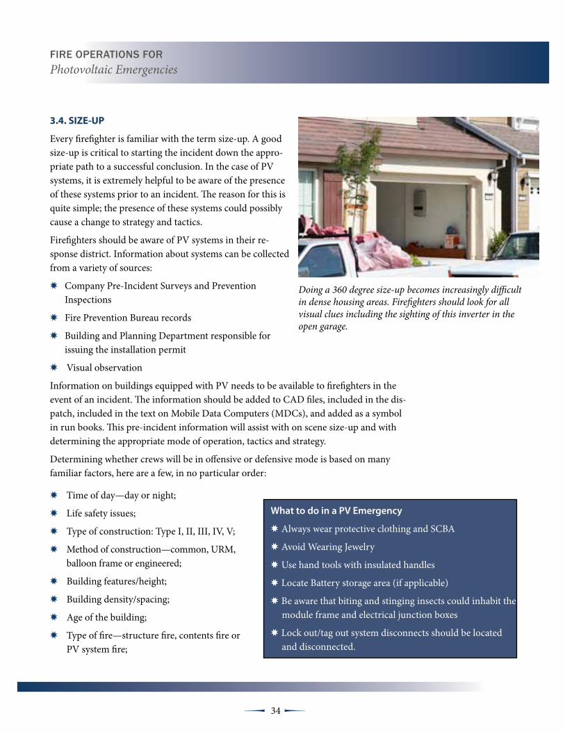
Doing a 360 degree size-up becomes increasingly difficult in dense housing areas. Firefighters should look for all visual clues including the sighting of this inverter in the open garage.
What to do in a PV Emergency
✸Always wear protective clothing and SCBA
✸Avoid Wearing Jewelry
✸Use hand tools with insulated handles
✸Locate Battery storage area (if applicable)
✸Be aware that biting and stinging insects could inhabit the module frame and electrical junction boxes
✸Lock out/tag out system disconnects should be located and disconnected.

Fire OperatiOns FOr Photovoltaic Emergencies
35 µµ
✸ Volume/involvement of fire;
✸ Resources available;
✸ Lost time intervals between inception on-scene time.
✸ PV system present;
✸ The system is involved in the fire or is an exposure;
✸ The system or system modules are what’s burning.
✸ Type of system —rack mount or building integrated;
The strategy will be determined after these and other initial size-up factors are assessed and an Incident Action Plan (IAP) is developed.
Just as information about potential fire behavior, building and roof construc-tion is important to know during size-up, knowledge of the PV systems loca-tion and components will also be important factors in both pre-incident and “on-scene” size-up.
3.5 StRAtEgY ANd tACtICS
Strategy and tactics are the life blood of any incident. If these two pieces of the incident are not based on sound opera-tional policy, training, and a well thought out approach to the problem, the entire incident will be compromised.
In incidents in which PV Systems supply the building with power, the firefighters on scene need to be trained in identifying PV systems and the methods to control them. In addition, they must know how to adjust their assess-ment of the incident involving PV to ensure appropriate actions are applied to the incident.
In any incident, the desired outcome is to always mitigate and/or control the situation in a safe and efficient man-ner. The strategy and tactics firefighters choose are critical to both the outcome and the safety of all members working on the scene.

Fire OperatiOns FOr Photovoltaic Emergencies
36 µµ
3.5.1 Strategy
Generally, the strategic mode for a fire incident is either an offensive or a defensive attack. The Incident Commander might switch from one to the other but cannot accomplish both at the same time. Once the IC has completed the size-up and has chosen a strategy, the IC will assign the necessary tasks to the fire companies.
Fire fighters must quickly determine if the sys-tem itself is involved in the fire and if the system is able to be de-energized and notify the IC. The IC may need to adjust the strategy and poten-tially re-arrange the order of the tasks needed to deal with the PVs. If the IC chooses an offensive strategy it needs to be supported as any other fire with or without PV systems. However, the tactics used to support an offensive strategy may need to be flexible do to the presence of the PV system and the inability of firefighters to de-energize all of the electrical equipment.
The strategy selected by the IC should have “trig-ger points” that will allow the IC to assess the fires impact on the structure and change strategy if a delay in the attack caused by the PV system results in excessive lost time.
The modules on fire at the Long Beach Convention Center were damaged in shipping and field repaired by the manufacturer’s rep prior to installation.
The Utility Group should watch for visual indicators like these warning labels to identify the existence of additional electrical power sources to the building.
Another factor to be considered by the IC is the presence of the sun. A fire occurring during nighttime will allow for a different strategy than a fire during daylight. However, if the incident proceeds past sunrise, the IC must be aware that the sunlight will cause the panels to become energized and the initial strategy may need to be adjusted accordingly.
3.5.2 tactics
Tactics are generally based upon the selected strategy and chosen objectives. As with the strategy, the implementation of tactics may be affected by the presence of a PV system. In buildings equipped with PV systems, control of the utili-ties must include control of the PV system as well as the local utility supplied power. In addition to de-energizing equipment powered by the local utility, the Utility Group must also de-energize electrical circuits lead-ing from the PV system. The Utility group should locate and disconnect any and all switches in the PV system,
Fire OperatiOns FOr Photovoltaic Emergencies
37 µµ
including switch-gear on the roof, switches on either side of an inverter and any switches in the connection to the building’s main electrical system.
In PV systems, there is always the possibility of energized con-ductors within conduit during daylight; therefore, knowledge of the location of PV system conduit is important to firefighters performing tasks such as ventilation and overhaul. When pos-sible, the Utility Group should also determine the location of all electrical conduits leading away from the array or otherwise connected to the PV system. Prior to overhaul, the Utility Group may consider marking the PV system conduit with bright spray paint or other means that will be understood by other firefighters working around the conduit.
If the system is “off-grid,” the Utility Group should determine if the building is served by other electrical sources in addition to the PV system. These may include fuel powered, wind and hydroelectric generators. The Utility Group should attempt to isolate all of the sources, includ-ing the PV, by locating the system controls and opening the main disconnects.
A Ventilation Group or Roof Division should advise the IC if the PV array is going to impact the crew’s ability to ventilate the structure effectively from above. If vertical ventilation can-not be accomplished, the IC needs to be notified immediately so that strategies and tactics can be adjusted. Changing to another form of ventilation requires coordination with the IC and interior crews.
3.6 COMMuNICAtIONS
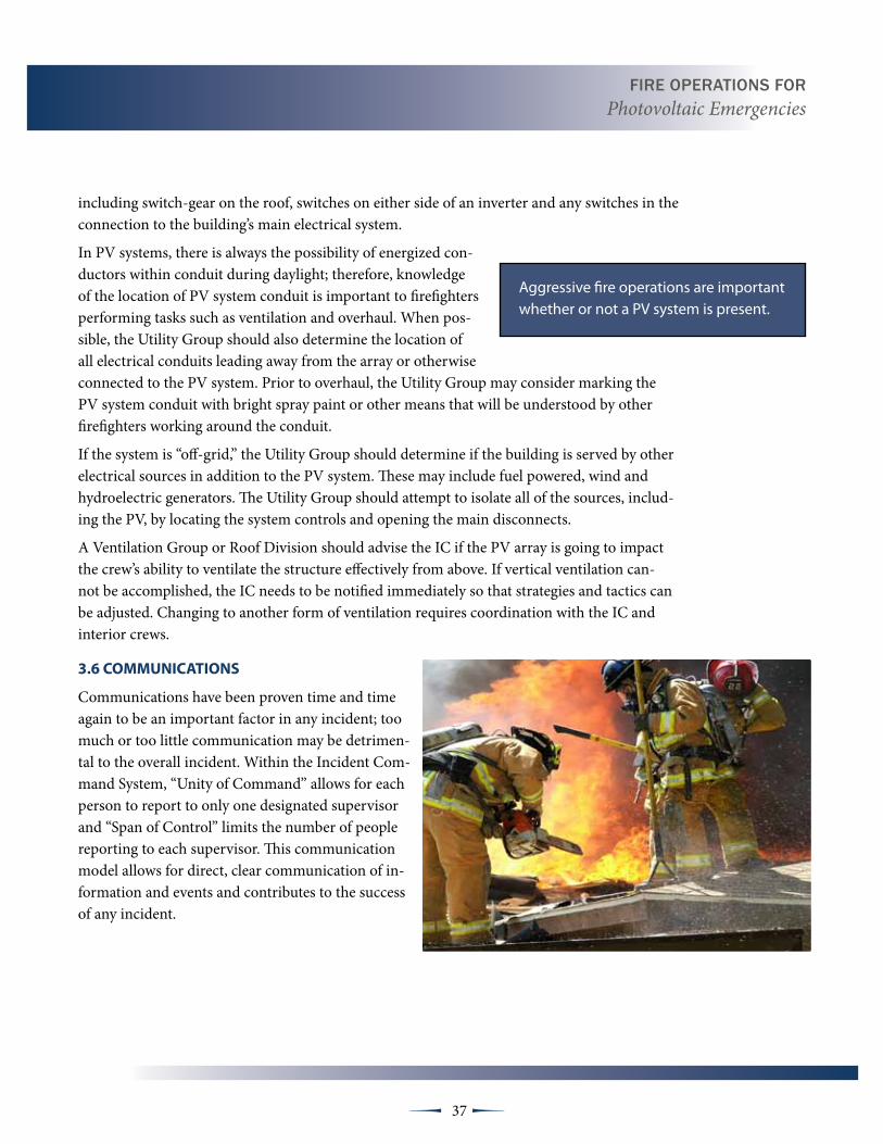
Communications have been proven time and time again to be an important factor in any incident; too much or too little communication may be detrimen-tal to the overall incident. Within the Incident Com-mand System, “Unity of Command” allows for each person to report to only one designated supervisor and “Span of Control” limits the number of people reporting to each supervisor. This communication model allows for direct, clear communication of in-formation and events and contributes to the success of any incident.
Aggressive fire operations are important whether or not a PV system is present.

Fire OperatiOns FOr Photovoltaic Emergencies
38 µµ
Good fire ground communications have some very basic and specific characteristics that should always be used during an incident. Fire ground communication should be clear, concise and informative. Some of the communications normally heard on the fire ground frequency are:
✸ Initial size-up
✸ Initial mode of operation
✸ Tactical assignments
✸ Command changes
✸ Primary and secondary search findings
✸ Progress up dates
✸ Time intervals
✸ Accountability—Personal Accountability Re-ports (PAR), Conditions Actions Needs (CAN), Personnel Position Progress Needs (PPPN), etc.
✸ Hazard notifications
✸ Emergency Traffic and broadcasts
✸ Changes in operational mode
Communications at incidents that involve PV systems should not be different than com-munications at any other incident. However, some of the communications will involve terms and phrases found throughout this training program that may be specific to the PV systems and how the system will impact the overall operation. Training officers, company officers and firefighters should include PV scenarios in training so that terms such as PV, BIPV, array, in-verter, ac, dc and other terms used when describing components of a PV system are familiar to firefighters and can be used during fires when PV systems are present.

Fire OperatiOns FOr Photovoltaic Emergencies
39 µµ
3.7 FIRE gROuNd OPERAtIONS
Offensive fire ground operations involving any structure with a PV system will require personnel to take certain precautions. Common PV hazards include;
✸ Electric shock
✸ Hazardous atmosphere
✸ Explosion/arc-flashing
✸ Collapse
✸ Trip, slip or fall
While these hazards aren’t unusual to firefighters operating on the fire ground, they may be accentuated by a PV system. The existence of a PV system will not necessarily prevent the initiation of offensive tactics; the system may have no impact on the fire whatsoever. Tac-tics necessary to perform rescues, exposure protection, confinement, extinguishment, salvage, ventilation and overhaul can and should still be initiated within buildings that have PV systems. However, the pos-sible additional hazards that may be created by a PV system should always be considered before undertaking any of these operations.
Recognizing the hazards, the use of protective gear, and avoidance of the PV system components will be fire fighters best defense when working around PV systems. However, the possible additional haz-ards that may be created by a PV system should always be considered
As discussed in previous sections, PV systems may not be obvious to firefighters approaching a building from the street level. In many modern subdivisions building integrated PV, such as PV shingles or building sidewalls may make the PV system difficult to detect. In densely populated urban areas with little or no access to the sides and rear of a structure, the ability of first arriving companies to complete a 360° size-up will be limited. Roof operations personnel or the Util-ity Group may be the first to locate a PV system. Early recognition of and communications about the PV system by firefighters operat-ing on the fire ground is imperative. This information will aid the Incident Commander and other personnel in establishing a strategy, determining risk, and prioritizing their tactical objectives.
During day time incidents involving a PV system, it’s important to remember that the panels are always producing energy. The In-cident Commander should assign a Utilities Group to locate and
During day time incidents involv-ing buildings with a PV system it is important to remember that the panels are always “Hot”
Fire OperatiOns FOr Photovoltaic Emergencies
40 µµ
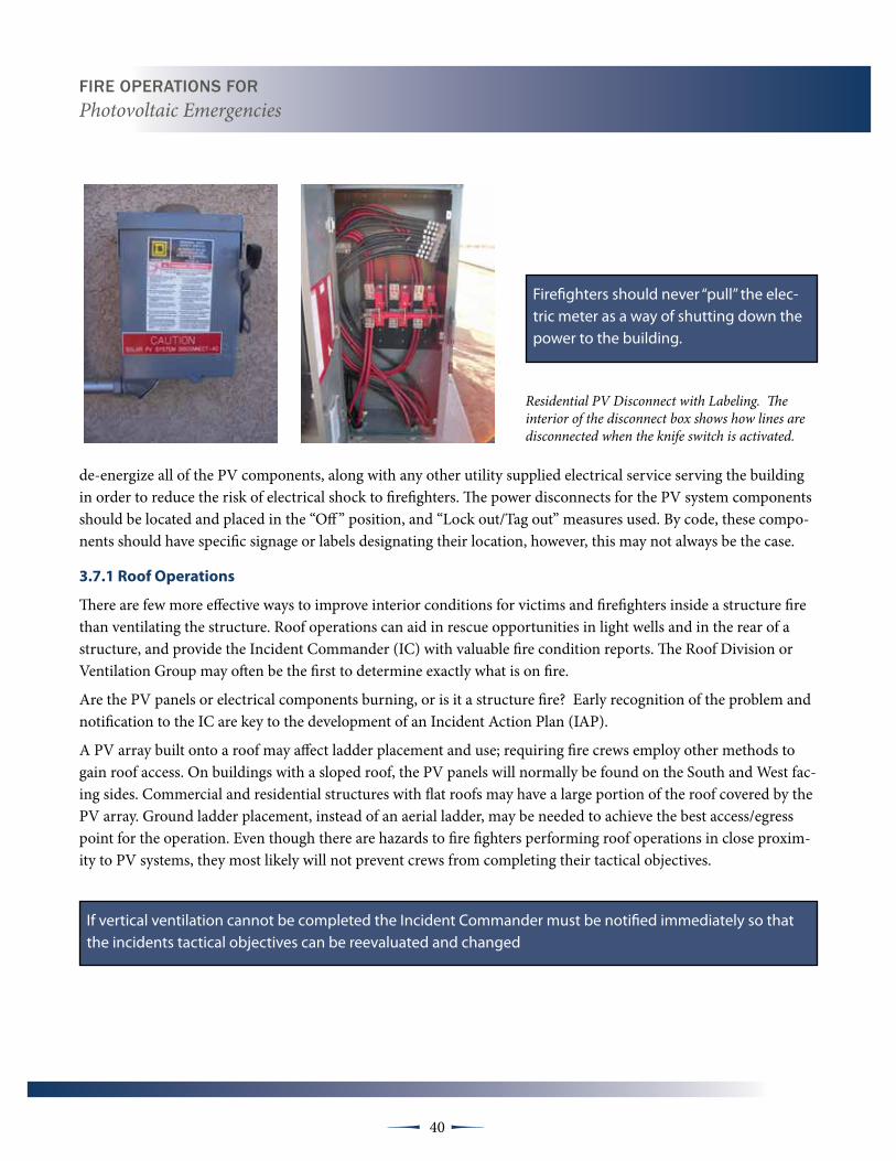
de-energize all of the PV components, along with any other utility supplied electrical service serving the building in order to reduce the risk of electrical shock to firefighters. The power disconnects for the PV system components should be located and placed in the “Off ” position, and “Lock out/Tag out” measures used. By code, these compo-nents should have specific signage or labels designating their location, however, this may not always be the case.
3.7.1 Roof Operations
There are few more effective ways to improve interior conditions for victims and firefighters inside a structure fire than ventilating the structure. Roof operations can aid in rescue opportunities in light wells and in the rear of a structure, and provide the Incident Commander (IC) with valuable fire condition reports. The Roof Division or Ventilation Group may often be the first to determine exactly what is on fire.
Are the PV panels or electrical components burning, or is it a structure fire? Early recognition of the problem and notification to the IC are key to the development of an Incident Action Plan (IAP).
A PV array built onto a roof may affect ladder placement and use; requiring fire crews employ other methods to gain roof access. On buildings with a sloped roof, the PV panels will normally be found on the South and West fac-ing sides. Commercial and residential structures with flat roofs may have a large portion of the roof covered by the PV array. Ground ladder placement, instead of an aerial ladder, may be needed to achieve the best access/egress point for the operation. Even though there are hazards to fire fighters performing roof operations in close proxim-ity to PV systems, they most likely will not prevent crews from completing their tactical objectives.
Firefighters should never “pull” the elec-tric meter as a way of shutting down the power to the building.
If vertical ventilation cannot be completed the Incident Commander must be notified immediately so that the incidents tactical objectives can be reevaluated and changed
Residential PV Disconnect with Labeling. The interior of the disconnect box shows how lines are disconnected when the knife switch is activated.
Fire OperatiOns FOr Photovoltaic Emergencies
41 µµ
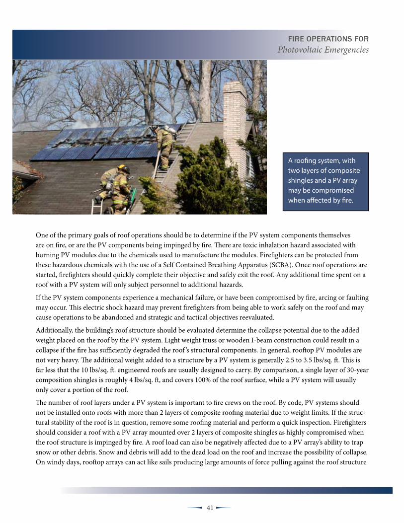
One of the primary goals of roof operations should be to determine if the PV system components themselves are on fire, or are the PV components being impinged by fire. There are toxic inhalation hazard associated with burning PV modules due to the chemicals used to manufacture the modules. Firefighters can be protected from these hazardous chemicals with the use of a Self Contained Breathing Apparatus (SCBA). Once roof operations are started, firefighters should quickly complete their objective and safely exit the roof. Any additional time spent on a roof with a PV system will only subject personnel to additional hazards.
If the PV system components experience a mechanical failure, or have been compromised by fire, arcing or faulting may occur. This electric shock hazard may prevent firefighters from being able to work safely on the roof and may cause operations to be abandoned and strategic and tactical objectives reevaluated.
Additionally, the building’s roof structure should be evaluated determine the collapse potential due to the added weight placed on the roof by the PV system. Light weight truss or wooden I-beam construction could result in a collapse if the fire has sufficiently degraded the roof ’s structural components. In general, rooftop PV modules are not very heavy. The additional weight added to a structure by a PV system is generally 2.5 to 3.5 lbs/sq. ft. This is far less that the 10 lbs/sq. ft. engineered roofs are usually designed to carry. By comparison, a single layer of 30-year composition shingles is roughly 4 lbs/sq. ft, and covers 100% of the roof surface, while a PV system will usually only cover a portion of the roof.
The number of roof layers under a PV system is important to fire crews on the roof. By code, PV systems should not be installed onto roofs with more than 2 layers of composite roofing material due to weight limits. If the struc-tural stability of the roof is in question, remove some roofing material and perform a quick inspection. Firefighters should consider a roof with a PV array mounted over 2 layers of composite shingles as highly compromised when the roof structure is impinged by fire. A roof load can also be negatively affected due to a PV array’s ability to trap snow or other debris. Snow and debris will add to the dead load on the roof and increase the possibility of collapse. On windy days, rooftop arrays can act like sails producing large amounts of force pulling against the roof structure
A roofing system, with two layers of composite shingles and a PV array may be compromised when affected by fire.

Fire OperatiOns FOr Photovoltaic Emergencies
42 µµ
under the panels. The Incident Commander and roof personnel should evaluate the structural hazards the array’s present and make the determination to abandon roof operations if necessary.
PV panels, mounting systems, and conduit present a trip, slip and fall hazard to firefighters. This is particularly true under two circumstances:
✸ BIPV shingles built into a sloped roofs shingle system can be extremely slippery and haz-ardous to firefighters walking on them.
✸ Because PV arrays on commercial structures often cover large portions of the roof, there may be very little clear space on which to walk.
Night operations, weather and smoky conditions will only compound these issues. Crews must move and work with additional caution because of these hazards. If possible, the tactical operations to be carried out on the roof should be done away from all PV components. Roof personnel may need to reevaluate their position and access the roof from an alternate location. Emergency egress points need to be determined early in the operation. Avoid positioning you and your crew so that the PV system is between you and your escape route. Situational aware-ness is key when operating near PV components.
Because PV panels continuously produce electricity during daylight, it may prove difficult to remove all burning or smoldering materials from under or around the panels without subject-ing crews to an electric shock hazard. Removal of the panels, unless done by a qualified PV technician or electrician, is not recommended and strongly discouraged. Firefighters may find it necessary to contain the fire and prevent its spread until the panels can be safely removed. It is strongly recommended that fire departments maintain a list of several licensed solar power installers or electricians that are willing to assist their department in securing or de-energizing PV systems and components in the event of an emergency.
3.7.2 ventilation Operations
PV panels located on the roof may present a significant obstacle for fire fighters assigned to ventilate. Vertical ventilation can be delayed or prevented because of the size and location of a building’s PV system. Cutting a ventilation hole directly over the fire will not be possible if the area is covered by a PV array or it’s structural support frame. Ventilation operations must be limited to those areas of the roof that are clear of the PV array and other components. If ven-tilation operations have to be done in close proximity to a PV system firefighters must be sure they do not cut or otherwise damage any of the system components. If possible, a safety officer
Not only are PV modules slippery when wet, they are not designed carry weight and therefore should not be walked on by firefighters.

Fire OperatiOns FOr Photovoltaic Emergencies
43 µµ
should be established to oversee operations when firefighters are work in close proximity to the PV array.
PV system conduit containing energized conductors on the roof deck and in attic spaces poses a serious shock hazard to firefighters performing ventilation. Crews must work together to prevent dam-age to any PV components with their tools or actions. If vertical ventilation cannot be completed, the IC must be notified imme-diately so that the incident strategy and tactics can be reevaluated and changed, if necessary. Horizontal or positive pressure ven-tilation may have to be used to perform ventilation if the roof is obstructed by the PV array or other system components.
3.7.3 Interior Operations
Interior fire ground operations may also be affected by a build-ings PV system. Energized system components located inside the building may create an electric shock hazard for interior crews. PV system conduit and wiring can be located in any portion of the building, including equipment rooms, closets, garages and attic spaces. Personnel must avoid coming in contact with these hazards and notify the Incident Commander and other firefighters of their location. When engaging in firefighting tactics on structures that may have energized PV systems, the issue of whether or not to apply water is an important tactical decision. If possible, firefight-ers should avoid directing hose streams directly onto energized PV system components and use or dry chemical extinguishers, if possible. If water is used, the following recommendations from Pacific Gas & Electric’s (PG&E) Emergency Responders Training Program2 should be followed:
✸ There should be a minimum of 100 psi at the nozzle.
✸ The fog spray should be set at 30 degree fog pattern at 100 psi.
✸ Firefighters must be at least 33 feet away from the energized source.
✸ Straight streams or foam should not be used. They are excellent conductors and put the responder at great risk.
2 Source: “Responding To Utility Emergencies”; Pg. 63, 2004; Michael Callan, Public Safety Program Mgr, PG&E
Traditional “Hot Sticks” used by the fire service are not recommended because they are designed to test for ac power only.

Fire OperatiOns FOr Photovoltaic Emergencies
44 µµ
Further, the PG&E recommendations point out that the electrical resistance of the ground can change due to water runoff, thereby creating an additional hazard to firefighters.
Fire ground water usage on or near PV system components should be based on conditions found at the time of the incident and department SOPs. If water has to be directed on or near a PV system a 30 degree fog pattern at 100 psi should be used in order to prevent any electric current from traveling upstream toward firefighters applying the water. Firefighters also need to be cau-tious of the electric shock hazard created by puddles of water.
The Utility Group, when assigned, should be tasked with locating and disconnecting all power sources supplying the building. These could include PV systems, electrical utility service, fuel, wind and hydroelectric generator sources. These disconnects may be nu-merous and in multiple locations. PV system and other electrical source disconnect switches must be located and “locked out”.
It is important to remember that the PV modules and arrays will still produce electricity to the inverter during daylight hours and that an electric shock hazard exists. Traditional energy sens-ing “Hot Sticks” used by the fire service are not recommended because they are designed to test for ac current and voltages only. Some department members may have enough experience with electricity to use an ac/dc multi-meter to confirm that power iso-lation has been achieved, otherwise, it is strongly recommended that firefighters wait for the arrival of a qualified solar technician or electrician.
If present, battery banks can also present toxic and explosion hazards for interior firefighting crews. The fumes and gases gen-erated by batteries exposed to fire are corrosive and flammable. Spilled battery electrolyte can produce toxic and explosive gasses if it comes in contact with other metals. Because of these hazards, water as an extinguishing agent should be avoided if possible. or dry chemical extinguishers are strongly recommended for extin-guishing fires involving lead-acid batteries.
Firefighters should never cut battery cables as a means of dis-abling a bank of batteries. Even after the batteries have been isolated from the electrical generating system, the batteries still have electric shock potential. Crews must wear full personal
The Utility Group, when assigned, should be tasked with locating and disconnecting all power sources sup-plying the building

Fire OperatiOns FOr Photovoltaic Emergencies
45 µµ
protective equipment (PPE) and SCBA when dealing with an emergency involving PV system battery banks. Due to the high degree of hazards as-sociated with these batteries, the IC may have to stop interior operations and reevaluate the strategy until the hazardous atmosphere can be tested and mitigated through ventilation. Hazmat teams with specific protective clothing may need to be called to the scene to aid in operations.
3.7.4 Search Operations
Search and rescue is the first tactical priority firefighters when approaching any fire scene. Searching under extreme heat and smoke conditions, often in zero visibility and with no hose line for protection, makes this one of the most dangerous tasks done on the fire ground. Search teams conduct-ing primary and secondary searches for victims may unknowingly come in contact with energized PV components that may have been damaged by the fire and lay exposed. The location of the components must be immedi-ately relayed to the IC and all personnel working on scene, and disconnect switches turned “OFF”.
3.7.5 Overhaul
Overhaul is an important task performed during the later stages of every fire in order to ensure complete extinguishment and prevent rekindle. Firefighters engaged in overhaul operations need to be aware that a build-ing’s PV system conduit can be hidden behind walls and in attic spaces. In buildings equipped with PV, the use of tools to breach walls and ceilings to search for fire extension must be performed with extra caution. This is particularly true during daylight hours when some PV components are energized. Whenever possible, the IC should delay overhaul until there is competent confirmation that the PV system has been “de-energized.”
Once the fire has been extinguished personnel safety is still a critical con-cern and often can be taken for granted as the incident enters the stabiliza-tion phase of the IAP. Many fire ground injuries and even fatalities have oc-curred well after the fire is out. In recent years, a fire investigator was killed by the collapse of a freestanding chimney several days after fire companies left the scene.3
3 “Firefighter Fatalities in the United States in 1999,” National Fire Data Cen-ter, U.S. Fire Administration, July 2000.
Incidents involving PV systems are unique, in that energized components may remain within the structure or on the roof even after all common power has been disabled

Fire OperatiOns FOr Photovoltaic Emergencies
46 µµ
At the conclusion of an incident, demobilization and termination efforts should be directed at leaving the property in the safest condition possible.
An overhaul focused size-up and risk-benefit analysis should be conducted. Incidents involving PV systems are unique in that components may remain energized within the structure or on the roof even after all utility supplied power has been de-energized. Along with a structural stability assessment, hazard identification and the marking of any potentially energized areas should be a priority. Investigators, building officials, property owners, and/or building maintenance engineers should be properly notified of any hazards that may exist. A qualified PV technician or electrician should be called to the incident to de-energize any system that has been compromised or creates a hazard.
Transferring scene safety and security to an appropriate local, mu-nicipal authority may be an option if the fire department is unable to quickly secure the assistance of a qualified PV technician or electri-cian. All hazards should be appropriately marked or barricaded. Struc-tures should not be released by any agency until all obvious hazards have been eliminated.
NFPA 1561
5.3.24 The incident command-er shall be responsible for the continuation, transfer, and termination of command at an incident.
5.3.25 The incident com-mander shall order the demo-bilization of resources when appropriate.
5.3.26* The incident commander shall provide for control of access to the incident scene.
5.3.27 The incident commander shall make appropriate incident status notifications to key people, officials, and the agency administrator.
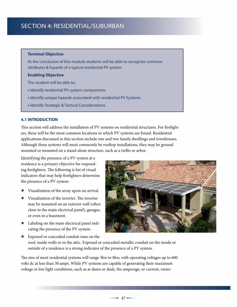
47 µµ
terminal Objective
At the conclusion of this module students will be able to recognize common attributes & hazards of a typical residential PV system.
Enabling Objective
The student will be able to:
• Identify residential PV system components
• Identify unique hazards associated with residential PV Systems
• Identify Strategic & Tactical Considerations
SECTION 4: RESIDENTIAL/SUBURBAN
4.1 INtROduCtION
This section will address the installation of PV systems on residential structures. For firefight-ers, these will be the most common locations in which PV systems are found. Residential applications discussed in this section include one and two family dwellings and townhouses. Although these systems will most commonly be rooftop installations, they may be ground mounted or mounted on a stand-alone structure, such as a trellis or arbor.
Identifying the presence of a PV system at a residence is a primary objective for respond-ing firefighters. The following is list of visual indicators that may help firefighters determine the presence of a PV system:
✸ Visualization of the array upon on arrival.
✸ Visualization of the inverter. The inverter may be mounted on an exterior wall (often close to the main electrical panel), garages, or even in a basement.
✸ Labeling on the main electrical panel indi-cating the presence of the PV system.
✸ Exposed or concealed conduit runs on the roof, inside walls or in the attic. Exposed or concealed metallic conduit on the inside or outside of a residence is a strong indicator of the presence of a PV system.
The size of most residential systems will range 3kw to 8kw, with operating voltages up to 600 volts dc at less than 30 amps. While PV systems are capable of generating their maximum voltage in low light conditions, such as at dawn or dusk, the amperage, or current, varies
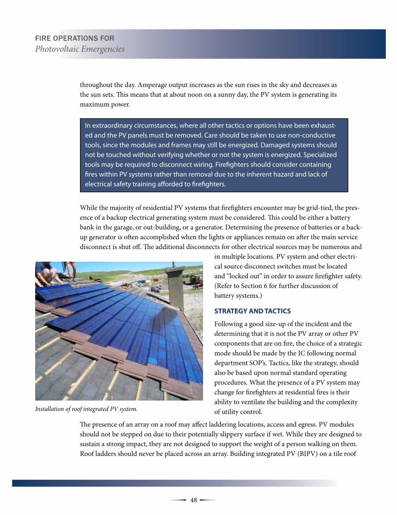
Fire OperatiOns FOr Photovoltaic Emergencies
48 µµ
throughout the day. Amperage output increases as the sun rises in the sky and decreases as the sun sets. This means that at about noon on a sunny day, the PV system is generating its maximum power.
In extraordinary circumstances, where all other tactics or options have been exhaust-ed and the PV panels must be removed. Care should be taken to use non-conductive tools, since the modules and frames may still be energized. Damaged systems should not be touched without verifying whether or not the system is energized. Specialized tools may be required to disconnect wiring. Firefighters should consider containing fires within PV systems rather than removal due to the inherent hazard and lack of electrical safety training afforded to firefighters.
While the majority of residential PV systems that firefighters encounter may be grid-tied, the pres-ence of a backup electrical generating system must be considered. This could be either a battery bank in the garage, or out-building, or a generator. Determining the presence of batteries or a back-up generator is often accomplished when the lights or appliances remain on after the main service disconnect is shut off. The additional disconnects for other electrical sources may be numerous and
in multiple locations. PV system and other electri-cal source disconnect switches must be located and “locked out” in order to assure firefighter safety. (Refer to Section 6 for further discussion of battery systems.)
StRAtEgY ANd tACtICS
Following a good size-up of the incident and the determining that it is not the PV array or other PV components that are on fire, the choice of a strategic mode should be made by the IC following normal department SOP’s. Tactics, like the strategy, should also be based upon normal standard operating procedures. What the presence of a PV system may change for firefighters at residential fires is their ability to ventilate the building and the complexity of utility control.
The presence of an array on a roof may affect laddering locations, access and egress. PV modules should not be stepped on due to their potentially slippery surface if wet. While they are designed to sustain a strong impact, they are not designed to support the weight of a person walking on them. Roof ladders should never be placed across an array. Building integrated PV (BIPV) on a tile roof
Installation of roof integrated PV system.

Fire OperatiOns FOr Photovoltaic Emergencies
49 µµ
may be hard to see at night, are very slick, and could easily result in a fall. Ladder placement may need repositioning once a PV or BIPV system is discovered.
Vertical ventilation is one of the tactics that may be employed. The coordination of the venting opera-tions on a building equipped with a PV system is a key component to the fire fight because the ventable area of the roof may be limited. Generally, firefighters ladder in the uninvolved area of the structure. However, this may not be possible due to the location of the PV array. Once the ladders are placed, an aggressive, coordinated opening should be made as close to the fire as possible. Coordination with the interior crews is important so that the opening is not made behind the crews, and so they are in a safe position if the ceiling is pushed down from above. Ideally, coordination with the Utilities Group is also needed because the Utilities Group may have some indication of where the PV system conduit is located.
Power saw and axe usage by the ventilation crew is of concern if the wiring run cannot be determined. Firefighters should give consideration to the depth of their cuts because the PV system conduit/wiring may be attached to the underside of the roof framing members. A good understanding of roof construc-tion and cutting techniques is vital to the safety of the firefighters when the building is equipped with a PV system.
In cases where the conduit run is in the attic or walls, care should be taken when pulling wall or ceiling material to avoid contact with the PV conduit. Should the conduit become separated at its joints, it may no longer be grounded and contact by a firefighter may result in an electrical shock.
When the fire involves only the PV system and not the building, the priorities change to protecting the structure from involvement. Firefighter’s initial efforts should be directed toward preventing the fire from
Fire departments should test their salvage covers on a PV array in advance of an incident to determine if they will successfully block light transmission.

Fire OperatiOns FOr Photovoltaic Emergencies
50 µµ
spreading to the roof or other nearby building components. If a portion of the array or other an electrical component is involved, or dry chemical extinguishers, or a 30° fog spray stream at 100 psi are the methods used to extinguish or confine the fire. Firefighters may have to continue their efforts to confine the fire to the system components for an extended period of time until a qualified PV technician arrives and assists in de-energizing the electrical equipment. Depending on the degree of damage and involvement of the system, there may be no protective grounding present, so contact with the array should be avoided.
The exclusion of light to de-energize the PV system is a tool that may be considered by the IC for residential PV systems. Testing conducted with both salvage covers and black plastic sheeting has proven to completely reduce the amount of energy produced by the PV system once it’s fully covered. Salvage covers used for this purpose should be dark in color. White or other light colored salvage covers should not be used as they permit enough light transmission to allow the system to continue to produce energy. Salvage covers or black plastic sheeting must be positively secured in place over the array. Uncovering of the array by the wind or otherwise will cause the system to produce energy. Fire departments should test their salvage covers on a PV array in advance of an incident to determine if they will successfully block light transmission.
At the conclusion of an incident, demobilization and termination efforts should be directed at leaving the property in the safest condition possible. An overhaul focused size-up and risk-benefit analysis should be conducted. Incidents involving PV systems are unique in that components may remain energized within the structure or on the roof even after all utility supplied power has been de-energized. Along with a structural stability assessment, hazard identification and the marking of any potentially energized areas should be a priority. Investigators, building officials, property owners, and/or building maintenance engineers should be properly notified of any hazards that may exist. A qualified PV technician or electrician should be called to the incident to de-energize any system that has been compromised or creates a hazard. Transferring scene safety and security to an appropriate local, municipal authority may be an option if the fire department is unable to quickly secure the assistance of a qualified PV technician or electrician. All hazards should be ap-propriately marked or barricaded. Structures should not be released by any agency until all obvious hazards have been eliminated.

51 µµ
terminal Objective
At the conclusion of this module students will be able to recognize common attributes and hazards of typical commercial photovoltaic systems.
Enabling Objective
The student will be able to:
• Identify commercial system components
• Identify unique hazards associated with commercial PV systems
• Identify strategy and tactical considerations
SECTION 5: COMMERCIAL LARGE AND SMALL
5.1 INtROduCtION
Although the number of residential sites greatly exceeds the number of commercial installa-tions, there is a similar amount of PV (in total Megawatts) installed in small and very large commercial installations. This is because commercial systems tend to be larger than residen-tial systems. Commercial installations include a broader variety of applications, given the greater variety of commercial structures and applications for solar. The most common systems are rooftop installations, but other installations may be located as a ground mount or mount-ed on a stand-alone structure, such as a parking shade cover.
Identifying the presence of a PV system is a primary objective for firefighters. Early recogni-tion of the presence of a PV system will aid in the development of strategic and tactical goals. Unlike residential systems, where the arrays are often visible from the ground, a large percent-age of commercial systems are installed on flat roofs and will not be visible from the ground. There may be large installations in communities that the local fire department is not aware of. Communication between the fire depart-ment and the permitting agency can help identify these systems in the community.
During size up, identifying a commercial system can be accomplished through the following components:
✸ Labeling on the main service panel upon arrival and PV system discon-necting means.
✸ Surface mounted conduit coming down from the roof along the side of the building.
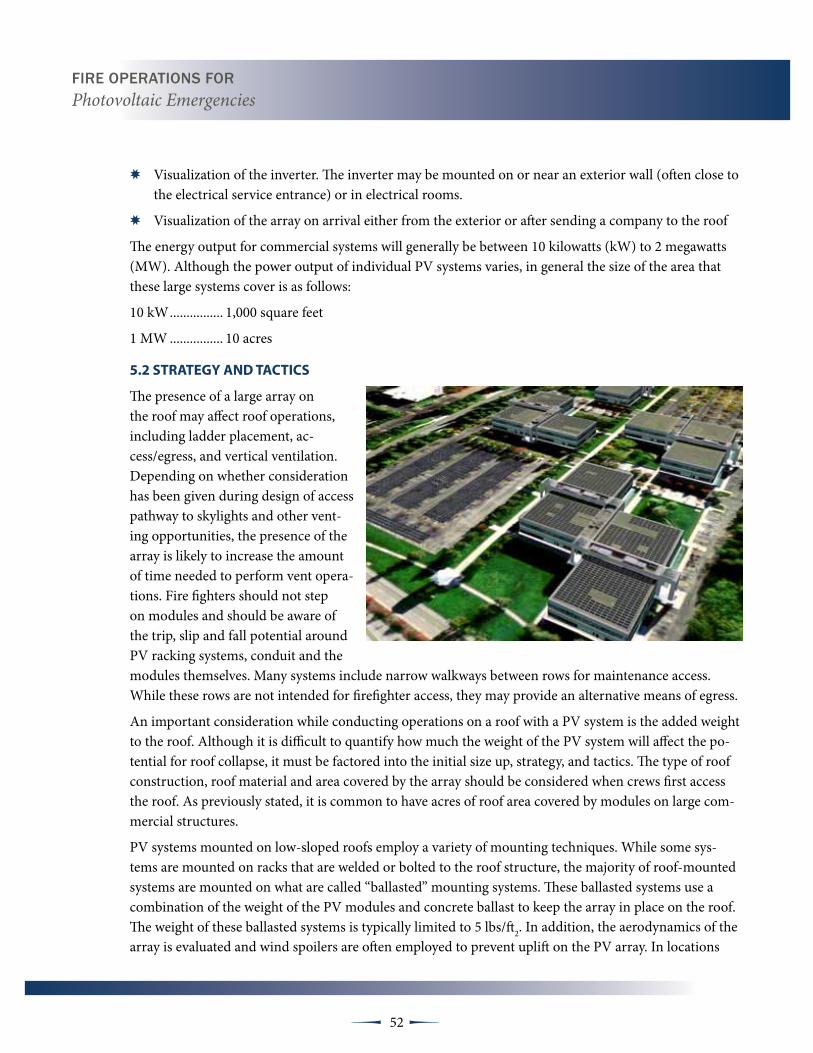
Fire OperatiOns FOr Photovoltaic Emergencies
52 µµ
✸ Visualization of the inverter. The inverter may be mounted on or near an exterior wall (often close to the electrical service entrance) or in electrical rooms.
✸ Visualization of the array on arrival either from the exterior or after sending a company to the roof
The energy output for commercial systems will generally be between 10 kilowatts (kW) to 2 megawatts (MW). Although the power output of individual PV systems varies, in general the size of the area that these large systems cover is as follows:
10 kW ................ 1,000 square feet
1 MW ................ 10 acres
5.2 StRAtEgY ANd tACtICS
The presence of a large array on the roof may affect roof operations, including ladder placement, ac-cess/egress, and vertical ventilation. Depending on whether consideration has been given during design of access pathway to skylights and other vent-ing opportunities, the presence of the array is likely to increase the amount of time needed to perform vent opera-tions. Fire fighters should not step on modules and should be aware of the trip, slip and fall potential around PV racking systems, conduit and the modules themselves. Many systems include narrow walkways between rows for maintenance access. While these rows are not intended for firefighter access, they may provide an alternative means of egress.
An important consideration while conducting operations on a roof with a PV system is the added weight to the roof. Although it is difficult to quantify how much the weight of the PV system will affect the po-tential for roof collapse, it must be factored into the initial size up, strategy, and tactics. The type of roof construction, roof material and area covered by the array should be considered when crews first access the roof. As previously stated, it is common to have acres of roof area covered by modules on large com-mercial structures.
PV systems mounted on low-sloped roofs employ a variety of mounting techniques. While some sys-tems are mounted on racks that are welded or bolted to the roof structure, the majority of roof-mounted systems are mounted on what are called “ballasted” mounting systems. These ballasted systems use a combination of the weight of the PV modules and concrete ballast to keep the array in place on the roof. The weight of these ballasted systems is typically limited to 5 lbs/ft2. In addition, the aerodynamics of the array is evaluated and wind spoilers are often employed to prevent uplift on the PV array. In locations

Fire OperatiOns FOr Photovoltaic Emergencies
53 µµ
where wind loads exceed the ability of the ballast and wind spoilers to hold the array, anchors are welded or bolted to the structure to provide an additional means to hold the PV array on the roof structure.
If the PV system is the source of the fire, then protection of the exposed structure is the primary con-cern. During daylight hours crews should consider all PV system modules and arrays energized and fight the fire as they would any other electrical fire. Crews should use or dry chemical extinguishers on any potentially energized PV component. If the roof material is on fire, a 30° fog stream at 100 psi can be used to prevent further spread of the fire without risk of shock to the firefighters. Firefighters, however, must be cautious of water pooling on the roof that could become energized. Care must be taken to avoid unnecessary contact with potentially energized PV components until they can be isolated and confirmed de-energized.
Depending on the level of damage to the system, the connection to “ground” may have been lost, contact with the PV system components should be avoided until the system is determined to be de-energized. Modules cannot be isolated during daylight hours and must always be considered energized. Firefighters working on and around PV systems should only use non-conductive tools, since the modules and frames may still be energized. Burning PV modules produce toxic vapors. Firefighters must wear full PPE and SCBA due to the toxic inhalation hazard produced by these burning components. Crews should work upwind of the smoke whenever possible.
In extraordinary circumstances, where all other tactics or options have been exhausted and the PV panels must be removed. Care should be taken to use non-conductive tools, since the modules and frames may still be energized. Damaged systems should not be touched without verifying whether or not the system is energized. Specialized tools may be required to discon-nect wiring. Firefighters should consider containing fires within PV systems rather than removal due to the inherent hazard and lack of electrical safety training afforded to firefighters.

Fire OperatiOns FOr Photovoltaic Emergencies
54 µµ
Damaged systems should never be touched without verifying whether or not the system is energized. Firefighters should never cut the wiring in a PV system. Specialized tools may be required for discon-necting the module wiring. Firefighters should consider controlling fires within PV systems rather than removal due to the inherent electrical hazard. Mounting systems, modules, and conduit should not be disassembled, damaged or removed by firefighters operating on the roof until all of the PV system’s com-ponents are isolated or de-energized by a qualified PV technician or electrician. Firefighters should limit their activities to containment of the fire until it can be confirmed that the system is isolated or de-energized.
At any incident where PV is present the IC must designate a “Utilities Group” early to aid in locating and disabling all of the buildings utilities and PV system components. This can greatly decrease the elec-tric shock hazard to all crews operating on the fire ground. Firefighters must remember that all PV components must be considered “HOT” during day light. Additionally, in large commercial systems, there is likely to be several arrays. Firefighters must be aware that if a single array is isolated, all of the others will most likely remain energized. Care must be exercised when operating the other energized arrays.
At the conclusion of an incident, demobilization and ter-mination efforts should be directed at leaving the prop-erty in the safest condition possible. An overhaul focused size-up and risk-benefit analysis should be conducted. Incidents involving PV systems are unique in that com-ponents may remain energized within the structure or on the roof even after all utility supplied power has been de-energized. Along with a structural stability assessment, hazard identification and the marking of any potentially energized areas should be a priority. Investigators, building officials, property owners, and/or building maintenance engineers should be properly notified of any hazards that may exist. A qualified PV technician or electrician should be called to the incident to de-energize any system that has been compromised or creates a hazard. Transferring scene safety and security to an appropriate local, municipal au-thority may be an option if the fire department is unable to quickly secure the assistance of a qualified PV technician or electrician. All hazards should be appropriately marked or barricaded. Structures should not be released by any agency until all obvious hazards have been eliminated.

55 µµ
terminal Objective
At the conclusion of this module students will understand what are ground mounted photovoltaic systems, hazards, size-up, strategy and tactics and the limited resources available in rural areas.
Enabling Objective
The student will be able to:
• Identify and learn what is ground mounted and where they may be located
• Identify hazards for ground mounted and rural PV systems
• Size-up, strategy and tactics may be different for ground mounted and rural areas compared to roof mounted PV systems
SECTION 6: GROUND MOUNT AND RURAL SYSTEMS
Photo is representative of these ground mounted systems, and depicts the nature of the array being remote from the facility.
6.1 INtROduCtION
Ground mounted PV systems generally stand alone and are supported by a framework that sits directly on the ground. These systems can vary in size from small 3 kilowatt (kW) system for a residence, up to several megawatts covering acres of land. Although the power output of individual PV systems varies, in general the size of the area that these ground mounted systems cover is as follows:
3 kW .................. 300 square feet
100 kW .............. half acre
1 MW ................ 10 acres
Ground mounted systems are used as trellises, car ports, shade structures, pedestrian walkways and other free standing structures with no purpose other than to support the PV arrays. Ground mounted PV systems are a viable alternative for facilities with sufficient land on which to place the arrays. Many farms, schools, waste water treatment plants, residences with large yards or open acreage, and many other types of facilities opt for a ground mounted installation rather than a roof mounted installation. You need to be aware that a ground mounted system may be supplying a facility that is located a significant dis-tance from the PV installation, to the extent that it may even be difficult to determine the location of the supplied facility.
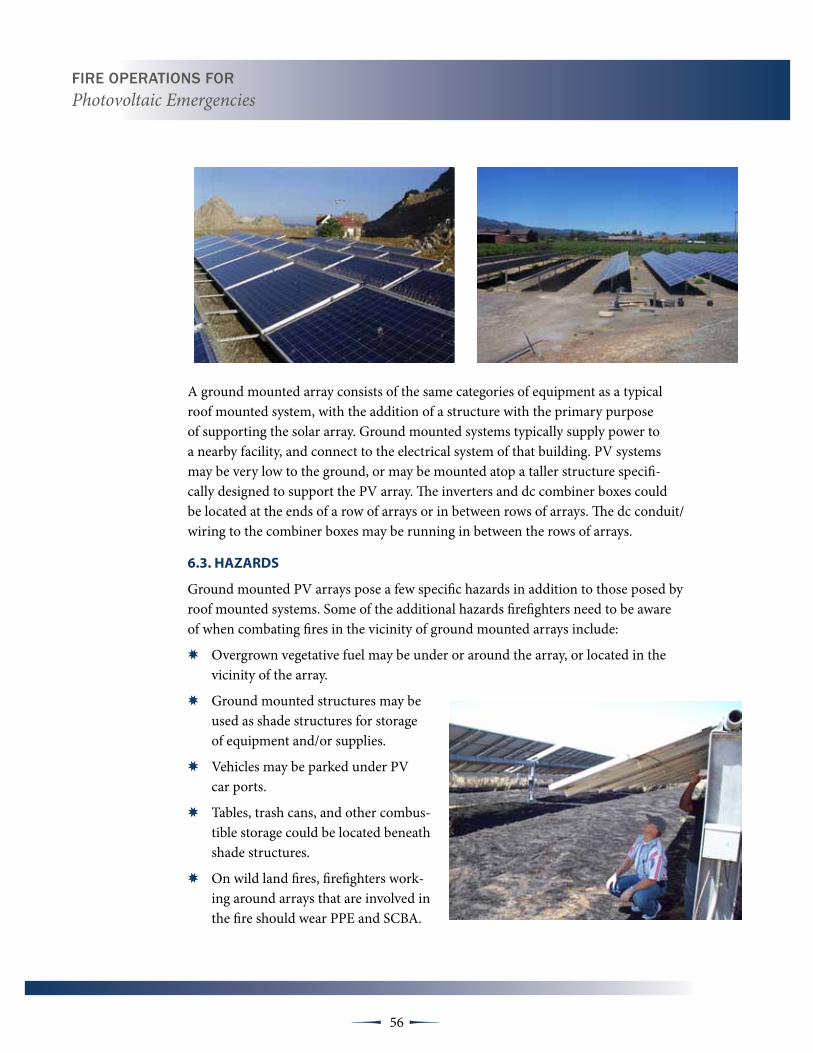
Fire OperatiOns FOr Photovoltaic Emergencies
56 µµ
A ground mounted array consists of the same categories of equipment as a typical roof mounted system, with the addition of a structure with the primary purpose of supporting the solar array. Ground mounted systems typically supply power to a nearby facility, and connect to the electrical system of that building. PV systems may be very low to the ground, or may be mounted atop a taller structure specifi-cally designed to support the PV array. The inverters and dc combiner boxes could be located at the ends of a row of arrays or in between rows of arrays. The dc conduit/wiring to the combiner boxes may be running in between the rows of arrays.
6.3. HAZARdS
Ground mounted PV arrays pose a few specific hazards in addition to those posed by roof mounted systems. Some of the additional hazards firefighters need to be aware of when combating fires in the vicinity of ground mounted arrays include:
✸ Overgrown vegetative fuel may be under or around the array, or located in the vicinity of the array.
✸ Ground mounted structures may be used as shade structures for storage of equipment and/or supplies.
✸ Vehicles may be parked under PV car ports.
✸ Tables, trash cans, and other combus-tible storage could be located beneath shade structures.
✸ On wild land fires, firefighters work-ing around arrays that are involved in the fire should wear PPE and SCBA.

Fire OperatiOns FOr Photovoltaic Emergencies
57 µµ
6.4. SIZE-uP
Given the different characteristics of a ground mounted array, a thorough size up needs to be performed so the firefighters at the incident understand the specific challenges posed by the ground mounted installation such as:
✸ Many ground mounted arrays may have access restricted by security fencing.
✸ Access roads may not be suited for all weather conditions, not maintained, or may be nonexistent.
✸ The PV system may be in a fire hazard severity zone.
✸ In rural areas, there may not be any fire hydrants or any addi-tional water supply.
✸ There could be a delay in locating the inverter or identifying other controls.
Ground mounted systems will vary widely in the design and details of the system; specifically equipment installations will vary from site to site. Disconnecting means are typically (but not always) provided to turn off the conductors connecting the array to the facility using the power. The disconnecting means is often mounted on the array structure or on a nearby backboard. At the building being served, there may also be a means to disconnect the power from the array.
The following is a partial list of typical system configurations you may encounter:
✸ The inverter and the ac and dc disconnect are at the array.
✸ The inverter and the dc disconnect are at the array. The ac disconnect is at the main service panel on the building being served.
✸ The dc disconnect is at the array. The inverter is at the building being served. The ac disconnect is at the main service panel on the building being served.
✸ The inverter is at the building being served. The dc disconnect is just upstream of the inverter and the ac disconnect is just downstream at the building being served.
✸ The inverter is at the building being served. The ac disconnect is at the main service panel on the building being served. The dc disconnect is just upstream of the inverter and at the array.
Large commercial arrays will have disconnects and inverters situated behind and protection by the PV array.

Fire OperatiOns FOr Photovoltaic Emergencies
58 µµ
6.5. StRAtEgY ANd tACtICS
Following a good size-up of the incident, the choice of a strategic mode should be made by the IC following normal department SOP’s. Tactics, like the strategy, should also be based upon normal standard operating procedures
6.5.1 Strategy
In addition to department policies, the following items must also be considered when develop-ing a strategy:
✸ Fire conditions found on arrival.
✸ Is it the array that’s burning or is a fire exposing the array?
✸ Threatened exposures including wild land areas
✸ Water and additional resources available
Once the IC has completed a size-up and developed an Incident Action Plan, the IC should de-termine the strategy and assign tasks to the fire companies. Due to the hazards associated with PV systems, the IC may need to adjust the strategy and potentially re-arrange the order of the tactics in order to deal specifically with the technology. If the IC chooses an offensive strategy it needs to be supported as any other fire operation with an emphasis on disabling all power sources to and from the PV system.
6.5.2 tactics
Tactics will be based on the chosen strategy and department SOP’s. If it is known that a PV System is present, utility control must become a primary objective. Isolation of the inverters and disconnecting the system from the main electrical panel will be an important task. The Utility Group should attempt to isolate all of the PV system by locating the system controls and opening all of the disconnect switches. The Utility Group must also look for and disable any other power source that can be connected to the system such as fuel, wind and hydro-electric powered generators.

Fire OperatiOns FOr Photovoltaic Emergencies
59 µµ
Another priority will be preventing further extension of the fire and isolating it to its area of origin. If the PV system itself is on fire it must be assumed to be “Hot” during daylight. Fire sup-pression crews should avoid physical contact with PV system components until it can be confirmed by a qualified PV techni-cian or electrician that all power sources have been isolated. It may take time for the technician to respond and locate all of the system controls.
or dry chemical extinguishers should be used to contain or ex-tinguish electrical fires. Water should be used to extinguish any ordinary combustibles under or near the ground mounted PV system, or if the volume of fire requires it use. If water is used, a 30º fog pattern from at least a 30 foot distance, at 100 psi is recommended. Full PPE must be used due to the potential toxic inhalation hazard if panels are burning. Fire crews should posi-tion themselves upwind and out of any toxic atmosphere.
During the overhaul and mop-up phases of the firefight, fire-fighters should avoid all potential electrical hazards until there is confirmation that the system no longer poses an electric shock hazard. Firefighters must avoid inadvertently damaging PV com-ponents with their tools. The IC may need the assistance from local PV technician to assist with disabling the PV system and confirmation that all of the hazards have been mitigated before incident is terminated and the scene is turned over to the owner or responsible party.
This ground mount array is equipped with a battery back-up system and battery meter or battery charge controller.


61 µµ
terminal Objective
At the conclusion of this module students will be able to recognize types of photovoltaic systems, components, hazards and related factors when systems are involved in emer-gency response and recognize and understand mitigation.
Enabling Objective
The student will be able to:
• Identify system components
• Identify hazards with PV systems
• Identify system locations
SECTION 7: OFF-GRID SYSTEMS
7.1 INtROduCtION
Off- grid, or stand-alone systems are defined as photovoltaic systems which are not connected to the local electrical utility’s supply grid. Off -grid systems generally produce electricity for use in close proximity to the PV array. While most off-grid systems use banks of batteries for the storage of electricity, some systems may not.
Off-grid systems are most often found in rural areas which are not well served by the electrical utility com-panies. Instead of the current produced being converted to alternating current, these systems may be used to directly power direct current (dc) lighting or motors. However, in most cases, the electricity produced during daylight hours will be “banked” in on-site batteries for later use. Once banked, the electricity may be used as dc or converted to alternating current (ac) by means of an inverter. Like grid-tied systems, off-grid systems may be located on a structure. However, in the rural setting, the systems may be ground, roof or pole mount-ed, or any combination thereof.
In addition to the hazards identified in grid-tied systems, off-grid systems have their own set of hazards that firefighters should be aware of. These include:
✸ Systems may have been installed without permits or inspection.
✸ Some components, such as charge controllers, may be “homemade”.
✸ Systems may lack discernable controls.
✸ Systems may lack signage.
✸ System components may be ungrounded.
✸ Battery storage banks may be located within rooms not suited for that purpose.
✸ Battery storage banks may be located in adjacent or “out” buildings.

Fire OperatiOns FOr Photovoltaic Emergencies
62 µµ
✸ Hydrogen gas, produced while charging the batteries, is flammable and can ignite or explode if allowed to collect in unvented spaces.
✸ Battery storage systems may have numerous exposed terminals and conductors.
✸ Batteries typically contain acid which may spill if the batteries are involved in a fire.
✸ Batteries may also receive charging current from other sources such as fuel powered generators and wind or water mills.
Indicators that a PV equipped structure is off-grid and may have battery storage sets include the lack of a “service drop” from adjacent power lines or the lack of a service panel and meter. The presence of a fuel, wind or hydro powered generator may also be an indication that the structure is off-grid. Firefighters ar-riving at an incident involving a PV system or fire involving a structure equipped with a PV system in rural areas should look for battery storage systems and alternative generating sources during their size-up.
As with any utility supplied electrical source, an effort should be made to disconnect, or shut off the electrical current. Disconnect switches for PV systems equipped with batteries can usually be located near the bat-tery bank and on the conductor(s) leading away from the batteries.
If the current coming from the batteries is being converted to AC, the disconnect switches and inverter may be configured in a manner similar to grid-tied systems; a disconnect switch located on the battery side, im-mediately upstream of the inverter.
Batteries used in storage systems are typically deep cycle batteries and rated 6, 12 or 24 volts DC. While individually these batteries have high amperage ratings, they lack sufficient voltage to cause life threatening injuries. However, if the batteries are connected in “series”, the voltage can easily be increased to dangerous levels. Firefighters should avoid cutting or disconnecting the jumper wires that connect batteries to each other or to the system because of the arcing that may occur. Firefighters should also be cautious when using metallic tools around batteries as contact with battery terminals could result in fusing of the tool to the terminal.
Whenever practical, dry chemical or CO2 extinguishers should be used on fires involving electrical equipment. This recommendation holds true for fires involving PV battery systems as well. As previously stated, typical batteries used for PV storage systems are lead- acid. When batteries are involved in fire, the plastic case con-taining the acid will melt, spilling the strong acid solution and creating a hazardous materials problem.

63 µµ
terminal Objective
At the conclusion of this module students will be able to recognize types of photovol-taic systems, components, hazards and related factors when systems are involved in emergency response and recognize and understand mitigation.
Enabling Objective
The student will be able to:
• Identify system components
• Identify hazards with PV systems
• Identify system locations
8.1 INtROduCtION
New products that convert solar energy to electricity are constantly under development. Some may be placed in service and some may go by the wayside. In the future, it is likely that firefighters may need to be familiar with a wide variety of solar technologies in addition to the pho-tovoltaic systems that have been discussed in this training course. As with many evolving technologies, there will be some developments that will reach the market and some that won’t. The following is a list of technologies currently being developed:
Curtain walls/BIPv. New high rise buildings may incorporate PV modules into the curtain walls on the south and west sides of the build-ing. These systems are already in use in some locations in the US, Asia, and Europe. Of concern to emergency responders is vertical fire spread across what would otherwise be a non-combustible surface. Additionally, some of the modules (thin film) incorporate 2 layers of non-tempered glass, which could result in an increased falling glass hazards on the fire ground.
Smart Modules (Module level control). Several products are either in development or commercially available. This technology could put a higher level of communications and control at each module. They are marketed for increased performance in shaded conditions and energy production. The benefit to firefighters is that technology allows them to shut down power at the “module level” in the event of an electrical short or fire. This technology could be used by emergency responders to provide module level shut off in the event of a fire.
SECTION 8: FUTURE SOLAR TECHNOLOGIES
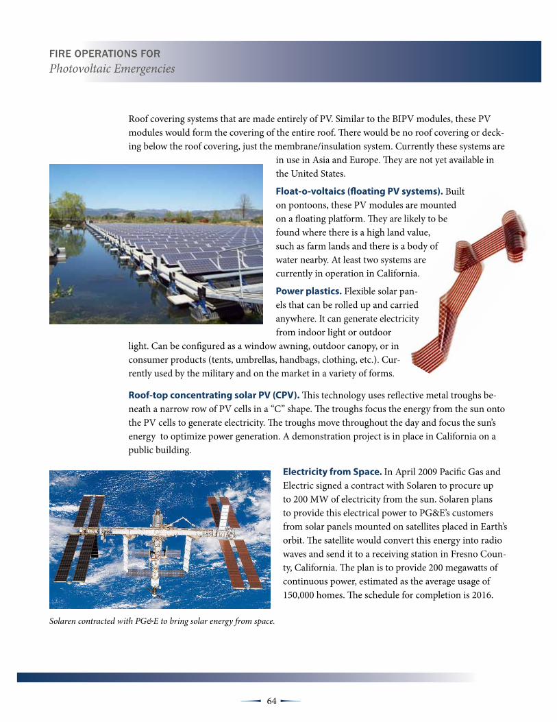
Fire OperatiOns FOr Photovoltaic Emergencies
64 µµ
Roof covering systems that are made entirely of PV. Similar to the BIPV modules, these PV modules would form the covering of the entire roof. There would be no roof covering or deck-ing below the roof covering, just the membrane/insulation system. Currently these systems are
in use in Asia and Europe. They are not yet available in the United States.
Float-o-voltaics (floating Pv systems). Built on pontoons, these PV modules are mounted on a floating platform. They are likely to be found where there is a high land value, such as farm lands and there is a body of water nearby. At least two systems are currently in operation in California.
Power plastics. Flexible solar pan-els that can be rolled up and carried anywhere. It can generate electricity from indoor light or outdoor
light. Can be configured as a window awning, outdoor canopy, or in consumer products (tents, umbrellas, handbags, clothing, etc.). Cur-rently used by the military and on the market in a variety of forms.
Roof-top concentrating solar Pv (CPv). This technology uses reflective metal troughs be-neath a narrow row of PV cells in a “C” shape. The troughs focus the energy from the sun onto the PV cells to generate electricity. The troughs move throughout the day and focus the sun’s energy to optimize power generation. A demonstration project is in place in California on a public building.
Electricity from Space. In April 2009 Pacific Gas and Electric signed a contract with Solaren to procure up to 200 MW of electricity from the sun. Solaren plans to provide this electrical power to PG&E’s customers from solar panels mounted on satellites placed in Earth’s orbit. The satellite would convert this energy into radio waves and send it to a receiving station in Fresno Coun-ty, California. The plan is to provide 200 megawatts of continuous power, estimated as the average usage of 150,000 homes. The schedule for completion is 2016.
Solaren contracted with PG&E to bring solar energy from space.

Fire OperatiOns FOr Photovoltaic Emergencies
65 µµ
Solar-paint. A group in the United Kingdom is currently developing a PV energy producing paint. The paint is dye-sensitized to generate electricity which is then
transferred to a collection circuit. The paint is not expected to be as efficient as the types of solar modules you see today – but it may be less expensive.
It would be in the form of a liquid paste. The paint is designed to be used on architectural steel but it may also have automotive applications. The
developers hope to have this product in commercial produc-tion by 2014.
Full spectrum Pv. Full spectrum PV is currently in development. The advantage to full spectrum PV
systems is that the generate electricity of a much wider spectrum of light that the current systems
but in particular, they can generate electricity on cloudy days. A disadvantage for firefighters is
that lighting from ambient light sources, includ-ing scene lighting, will cause the PV modules to
produce electricity.
Like Solar-paint, PV glitter, or Microphotovoltaics, has the potential for a wide range of applications such as incorporating the material into an entire roof covering system or fabrics like clothes and tents to recharge portable electronics.
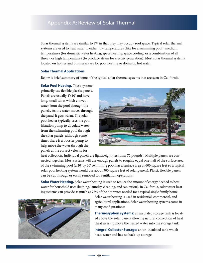
66 µµ
Solar thermal systems are similar to PV in that they may occupy roof space. Typical solar thermal systems are used to heat water to either low temperatures (like for a swimming pool), medium temperatures (for domestic water heating; space heating; space cooling; or a combination of all three), or high temperatures (to produce steam for electric generation). Most solar thermal systems located on homes and businesses are for pool heating or domestic hot water.
Solar thermal Applications
Below is brief summary of some of the typical solar thermal systems that are seen in California.
Solar Pool Heating. These systems primarily use flexible plastic panels. Panels are usually 4'x10' and have long, small tubes which convey water from the pool through the panels. As the water moves through the panel it gets warm. The solar pool heater typically uses the pool filtration pump to circulate water from the swimming pool through the solar panels, although some-times there is a booster pump to help move the water through the panels at the correct velocity for heat collection. Individual panels are lightweight (less than 75 pounds). Multiple panels are con-nected together. Most systems will use enough panels to roughly equal one-half of the surface area of the swimming pool (a 20' by 30' swimming pool has a surface area of 600 square feet so a typical solar pool heating system would use about 300 square feet of solar panels). Plastic flexible panels can be cut through or easily removed for ventilation operations.
Solar water Heating. Solar water heating is used to reduce the amount of energy needed to heat water for household uses (bathing, laundry, cleaning, and sanitation). In California, solar water heat-ing systems can provide as much as 75% of the hot water needed for a typical single family home.
Solar water heating is used in residential, commercial, and agricultural applications. Solar water heating systems come in many configurations:
thermosyphon systems: an insulated storage tank is locat-ed above the solar panels allowing natural convection of heat (heat rises) to move the heated water into the storage tank.
Integral Collector Storage: an un-insulated tank which heats water and has no back-up storage.
Appendix A: Review of Solar Thermal

Fire OperatiOns FOr Photovoltaic Emergencies
67 µµ
Active systems: a system made up of one or more collectors and a storage tank. A pump is used to circulate heat transfer material through the collector back to the storage tank.
Thermosyphon Systems: where the heated water rises naturally from collector to storage tank.
Note: both thermosyphon and integral collector storage systems add significant weight to the roof which should be of concern to firefighters.
Active systems use a variety of heat transfer materials: potable water, food-grade propyl-ene glycol, or air. Systems that do not use water will include a heat exchanger to transfer the energy collected to the potable water in the storage tank.
Single family solar water heating systems typically use about 40-60 square feet of solar panels and they weigh less than 5 lbs/sq. ft (similar to PV) if they are not thermosyphon or integral collector storage systems.
Space conditioning. Space conditioning systems will typically be active systems de-signed to provide heat in the winter or air conditioning in the summer. Most, if not all of these systems, will produce more energy than is needed so they will use the extra energy to provide domestic hot water. All of these systems are custom designed and may be hooked to a radiant floor system or a radiator system. Space conditioning systems will usually use more overall square footage of solar panels than a system designed just to provide domestic hot water.
Solar thermal Components
Typical components of a solar thermal system include:
Collector(s). Solar thermal collectors come in several forms:
✸ A panel made up of risers attached to two manifolds. For low temperature applications (like pool heating) the panel is exposed to the elements. For low to medium temperature applications (domestic water heating and pool heating in cooler climates), the panel is placed in an insulated aluminum box with a glass cover.
✸ A trough with a focal point where energy is collected
✸ A plenum
✸ A low profile tank
Storage. Storage for solar thermal systems usually look like a typical household water heater. Larger systems may have larger custom storage tanks.
Pump. Not all systems have pumps but many have small recirculation pumps that turn on based on the temperature differential between the collector and the storage tank.

Fire OperatiOns FOr Photovoltaic Emergencies
68 µµ
Heat Exchanger. Not all systems have heat exchangers but many have them. Heat exchangers are located in the storage tank to transfer the energy collected from the solar panel and transfer it to the potable water in the storage tank.
Controller. A controller is used to monitor the temperature of the collector and the storage tank to control when the pump (if the system uses a pump). Low-voltage sensors are connected to the storage tank and the collectors.
Power block (for electric generation only). For systems that are used to generate electricity a power block will be attached to the solar thermal system to generate electricity. These systems are not currently seen anywhere except in utility scale applications.
Less Common Configurations
New solar thermal technologies are entering the market, in particular, combined solar thermal and PV systems. One approach to combine solar thermal and PV employs a plenum beneath the PV panel which is connected to a heat exchanger. Another approach is a system which uses focal mirrors to direct the sun’s energy to one or more focal points (one for solar thermal and a second for PV).
Solar water heating can be found in conjunction with solar electric panels.


