
Performance Improvement of Smart Grid
Communications Using
Multi-homing and Multi-streaming
SCTP
by
Majed Alowaidi
A thesis submitted to the
Faculty of Graduate and Postdoctoral Studies
In partial fulfilment of the requirements
For the M.A.Sc. degree in Electrical and Computer Engineering
Ottawa-Carleton Institute for Electrical and Computer Engineering
School of Electrical Engineering and Computer Science (EECS)
University of Ottawa
c⃝ Majed Alowaidi, Ottawa, Canada, 2012

Abstract
With the obvious evolution and acceleration of smart grid, it is crucial for its
success to rely on a solid transmission protocol among its peripherals due to its real
time streaming. TCP is the well known traditional transport protocol used for a
reliable transmission, and is a major player for smart grid. However, it lacks a fault
tolerance transmission method that overcomes potential failures which may mitigate
smart grid progress and in its turn decrease its reliability. We propose that smart
grid operators utilize SCTP as the principle transport protocol for their smart grid
communications, by using the two very significant characteristics offered by SCTP
multi-homing and multi-streaming respectively. Thus, we argue that they can override
two major obstacles caused by TCP Head of Line Blocking (HLB) and the inability
of handling automatically two or more paths to a final destination. Although SCTP
resembles TCP in many aspects, SCTP can definitely play a dominant role in many
current and future applications due to its key features that do not exist in TCP. We
have used ns2.34 simulator as the tool whom we relied on to investigate whether or
not smart grid may benefit over TCP by the two SCTP features, and have analyzed
the output of simulated results by using other analytical tools. As we obtain results,
we argue that smart grid operators should rely on SCTP as a feasible transmission
protocol instead of TCP.
ii

Acknowledgements
Many thanks and praise to my supervisor Professor El Saddik, who I admire
working under his supervision ....... Also, I’d like to express my appreciation for
the guidance and cooperation I found in my co-supervisor Professor Richard in my
research....... Lastly, I will never forget to thank my parents for their hope and prayers
for me. A Warm and grateful acknowledgement for my wife and children for their
continued support and patience during my work.
— Majed Alowaidi
April 2012
iii

Table of Contents
Abstract ii
Acknowledgements iii
List of Tables vii
List of Figures viii
1 Introduction 1
1.1 Research Overview . . . . . . . . . . . . . . . . . . . . . . . . . . . . 1
1.2 Motivation and Objectives . . . . . . . . . . . . . . . . . . . . . . . . 6
1.3 Contributions . . . . . . . . . . . . . . . . . . . . . . . . . . . . . . . 7
1.3.1 Submitted Papers . . . . . . . . . . . . . . . . . . . . . . . . . 8
1.4 Thesis Organization . . . . . . . . . . . . . . . . . . . . . . . . . . . . 8
2 Literature Review and Related Works 9
2.1 Smart Grid Communications . . . . . . . . . . . . . . . . . . . . . . . 9
2.2 SCTP Overview . . . . . . . . . . . . . . . . . . . . . . . . . . . . . . 14
2.2.1 SCTP Structure View . . . . . . . . . . . . . . . . . . . . . . 14
2.2.2 SCTP Packet Format . . . . . . . . . . . . . . . . . . . . . . . 17
2.3 SCTP Comparing to TCP . . . . . . . . . . . . . . . . . . . . . . . . 22
iv

2.4 Related Work . . . . . . . . . . . . . . . . . . . . . . . . . . . . . . . 25
2.4.1 Performance of SCTP for IPTV Applications . . . . . . . . . . 25
2.4.2 Measurement-Based Analysis of HoLB for SIP over TCP . . . 26
2.4.3 Performance Evaluation of a Transport Layer Solution for Seam-
less Vertical Mobility . . . . . . . . . . . . . . . . . . . . . . . 27
2.5 Summary . . . . . . . . . . . . . . . . . . . . . . . . . . . . . . . . . 27
3 Proposed Smart Grid Communications Using SCTP Multi-homing
and Multi-streaming 29
3.1 Redundant Paths by Multi-homing . . . . . . . . . . . . . . . . . . . 30
3.1.1 TCP Lack of Paths Management . . . . . . . . . . . . . . . . 30
3.1.2 Fault Tolerance by Multipath . . . . . . . . . . . . . . . . . . 31
3.2 Improve Performance with Multi-streaming . . . . . . . . . . . . . . . 33
3.2.1 HoLB Problem Scenario in TCP (makes it challenge for Smart
Grid) . . . . . . . . . . . . . . . . . . . . . . . . . . . . . . . . 34
3.2.2 Multi-Streaming Mechanism in SCTP . . . . . . . . . . . . . . 36
3.3 Summary . . . . . . . . . . . . . . . . . . . . . . . . . . . . . . . . . 39
4 Simulation Results and Discussion 41
4.1 Overview of Simulation Tools . . . . . . . . . . . . . . . . . . . . . . 41
4.1.1 Tool Used for Simulation . . . . . . . . . . . . . . . . . . . . . 43
4.2 Multi-Paths for Smart Grid Throughput Performance . . . . . . . . . 52
4.3 Multi-Streaming Messages for Delay Performance Improvement . . . 54
4.4 Results . . . . . . . . . . . . . . . . . . . . . . . . . . . . . . . . . . . 56
4.4.1 Smart Grid Throughput of each SCTP and TCP . . . . . . . 56
4.4.2 Delay measured in Smart Grid Communications for both SCTP
and TCP . . . . . . . . . . . . . . . . . . . . . . . . . . . . . 62
v
4.5 Summary . . . . . . . . . . . . . . . . . . . . . . . . . . . . . . . . . 67
5 Conclusions and Future Work 69
5.1 Conclusions . . . . . . . . . . . . . . . . . . . . . . . . . . . . . . . . 69
5.2 Future Work . . . . . . . . . . . . . . . . . . . . . . . . . . . . . . . . 71
References 73
A Simulation Scripts 73
A.1 Smart grid throughput multi-homing one node . . . . . . . . . . . . . 73
A.1.1 SCTP . . . . . . . . . . . . . . . . . . . . . . . . . . . . . . . 73
A.1.2 TCP . . . . . . . . . . . . . . . . . . . . . . . . . . . . . . . . 78
A.2 Smart grid throughput multi-homing three nodes . . . . . . . . . . . 83
A.2.1 SCTP . . . . . . . . . . . . . . . . . . . . . . . . . . . . . . . 83
A.2.2 TCP . . . . . . . . . . . . . . . . . . . . . . . . . . . . . . . . 91
A.3 Single home smart grid communications delay . . . . . . . . . . . . . 98
A.3.1 SCTP delay . . . . . . . . . . . . . . . . . . . . . . . . . . . 98
A.3.2 TCP delay . . . . . . . . . . . . . . . . . . . . . . . . . . . . 102
vi
List of Tables
2.1 SCTP Common Chunk Format . . . . . . . . . . . . . . . . . . . . . 21
2.2 A comparison of SCTP and TCP . . . . . . . . . . . . . . . . . . . . 24
4.1 Key differences between OpNet, OmNet++ and NS2 . . . . . . . . . 44
4.2 Format of SCTP trace file . . . . . . . . . . . . . . . . . . . . . . . . 48
4.3 Format of TCP trace file . . . . . . . . . . . . . . . . . . . . . . . . . 48
4.4 A comparison between ns2 and other simulation softwares [65] . . . . 51
vii

List of Figures
1.1 A basic SCTP Multi-homing feature . . . . . . . . . . . . . . . . . . 4
1.2 Multiple SCTP streams within a single association . . . . . . . . . . . 5
2.1 Smart Grid Architectural levels [5] . . . . . . . . . . . . . . . . . . . 10
2.2 Smart Grid Communications Layer . . . . . . . . . . . . . . . . . . . 11
2.3 European Smart Grid Communications Model [15] . . . . . . . . . . . 13
2.4 Two SCTP endpoints Association [4] . . . . . . . . . . . . . . . . . . 15
2.5 Four handshake Connection Establishment in SCTP . . . . . . . . . . 16
2.6 Connection Shutdown in SCTP . . . . . . . . . . . . . . . . . . . . . 17
2.7 SCTP Packet Format [4] . . . . . . . . . . . . . . . . . . . . . . . . . 18
2.8 SCTP Common Header Format [4] . . . . . . . . . . . . . . . . . . . 19
2.9 SCTP Common Chunk Format [4] . . . . . . . . . . . . . . . . . . . . 19
3.1 Multipath redundant using SCTP Multi-homing . . . . . . . . . . . . 33
3.2 TSN, SI and SSN for SCTP Multiple-steams [29] . . . . . . . . . . . 34
3.3 HoL Blocking problem in TCP [29] . . . . . . . . . . . . . . . . . . . 35
3.4 A Single and Multiple-Streams in SCTP [29] . . . . . . . . . . . . . . 37
3.5 SCTP Multi-streaming with in order delivery [30] . . . . . . . . . . . 38
4.1 The basic class hierarchy of ns2 [52] . . . . . . . . . . . . . . . . . . . 46
4.2 The ns basic architecture of C++ and OTcl [52] . . . . . . . . . . . . 47
viii

4.3 SCTP Multi-home in Smart Grid Communications . . . . . . . . . . 53
4.4 Multi-streaming in Smart Grid Environment . . . . . . . . . . . . . . 55
4.5 SCTP vs.TCP one Node Throughput in Multi-homed Connection of
Smart Grid . . . . . . . . . . . . . . . . . . . . . . . . . . . . . . . . 58
4.6 SCTP vs.TCP Three Nodes Throughput in Multi-homed Connection
of Smart Grid . . . . . . . . . . . . . . . . . . . . . . . . . . . . . . . 59
4.7 SCTP and TCP Packets affected by Handover in Smart Grid Multi-
homed Environment . . . . . . . . . . . . . . . . . . . . . . . . . . . 60
4.8 SCTP vs. TCP Throughput for Smart Grid Single Homed Topology . 61
4.9 SCTP delay of a Single Homed Topology for Smart Grid . . . . . . . 65
4.10 TCP delay of a Single Homed Topology for Smart Grid . . . . . . . . 65
4.11 SCTP and TCP Delays combined together of a Smart Grid Network . 66
ix
Chapter 1
Introduction
1.1 Research Overview
New innovations influence our lives styles. Our houses and offices are affected
by these changes due to our lives demands. There is no doubt that the undergoing
evolution of technology has major effects on our lives. Smart grid, which is one of
the most recent and important technologies, is intended to be a means of providing
the needs of electricity to end users in reliable, clean, interactive, data accessible,
and real-time manner by electricity operators. Smart grid is an immature technology,
yet technology has several definitions nowadays depending on the given sectors per-
spective. A general comprehensive definition of smart grid is: the digital control of
the power delivery network and two-way communication with customers and market
participants. This is done through the realization of a fully-automated power delivery
network that can ensure a two-way flow of electricity and information between power
plants, and appliances, and all points in between [1]. Globally smart grid has several
definitions which are all characterized by similar attributes. In United States, smart
grid definition can be summarized into some attributes [2] as follows:
1

• The ability of self healing or recovery in case of disturbances.
• Reactions to customers demands.
• Functions robustly against physical and Internet attacks.
• Enabler of new products of services.
• The most significant one is that it develops asset utilization and operating
efficiency.
In the European Commission view [2], smart grid is defined as a feasible flexi-
bility to customers needs, parallel to any changes or challenges that smart grid might
face. With high efficiency, local generation, and low carbon emission consumption,
smart grid is intended to be accessible to all kinds of networking users. Considering
economic issues, smart grid is able to provide affordability by using efficient energy
management. In the east, China is one of biggest countries developing intelligent
power grids. Smart grid brings forward another concept similar to the two mentioned
antecedently. The term smart grid refers to an electricity transmission and distri-
bution system that incorporates elements of both traditional and cutting-edge power
engineering, sophisticated sensing and monitoring technology, information technology,
and communications to provide better grid performance and to support a wide range
of additional services to consumers. A smart grid is not defined by what technologies
it incorporates but rather by what it can do [2]. A research conducted in [15], which
tried to brief potential challenges, solutions and standards of smart grid activities,
defined it as a network of intelligent electricity that integrates consumers actions and
handles their data whether it is advanced information, control, or communications
which result in energy saving, reduced costs, gained reliability, and transparency.
Smart grid vision includes a bidirectional communication among its nodes which is
2
not only an interactive action but also a proactive one to provide a fault tolerant
reaction which in turn avoids instability that is unwanted in many situations. That
means the integration among smart grid peripherals is the first priority which involves
a reliable transmission method that considers an electricity service such as smart grid,
in addition to its other attributes. Once we have the maximum reliability needed for
our electricity service, peak periods of electricity consumption can be avoided, result-
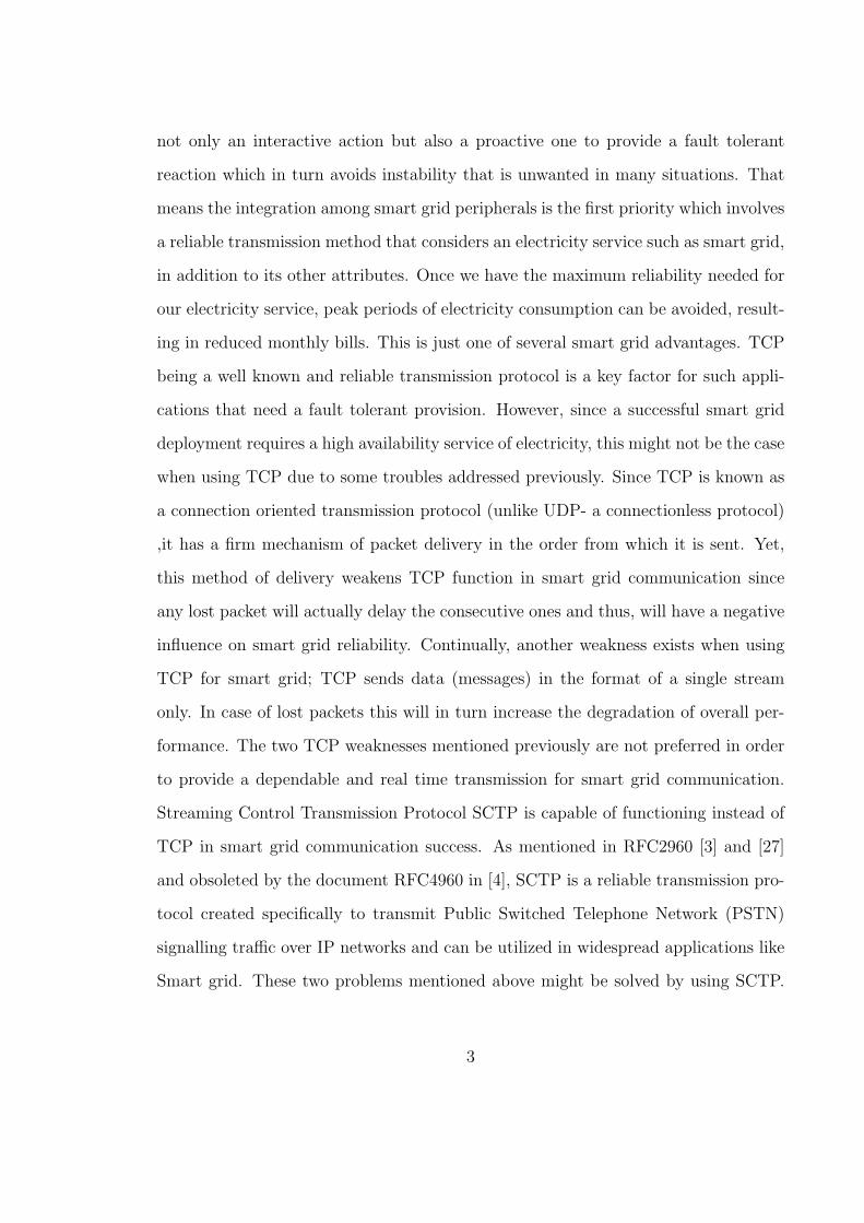
ing in reduced monthly bills. This is just one of several smart grid advantages. TCP
being a well known and reliable transmission protocol is a key factor for such appli-
cations that need a fault tolerant provision. However, since a successful smart grid
deployment requires a high availability service of electricity, this might not be the case
when using TCP due to some troubles addressed previously. Since TCP is known as
a connection oriented transmission protocol (unlike UDP- a connectionless protocol)
,it has a firm mechanism of packet delivery in the order from which it is sent. Yet,
this method of delivery weakens TCP function in smart grid communication since
any lost packet will actually delay the consecutive ones and thus, will have a negative
influence on smart grid reliability. Continually, another weakness exists when using
TCP for smart grid; TCP sends data (messages) in the format of a single stream
only. In case of lost packets this will in turn increase the degradation of overall per-
formance. The two TCP weaknesses mentioned previously are not preferred in order
to provide a dependable and real time transmission for smart grid communication.
Streaming Control Transmission Protocol SCTP is capable of functioning instead of
TCP in smart grid communication success. As mentioned in RFC2960 [3] and [27]
and obsoleted by the document RFC4960 in [4], SCTP is a reliable transmission pro-
tocol created specifically to transmit Public Switched Telephone Network (PSTN)
signalling traffic over IP networks and can be utilized in widespread applications like
Smart grid. These two problems mentioned above might be solved by using SCTP.
3
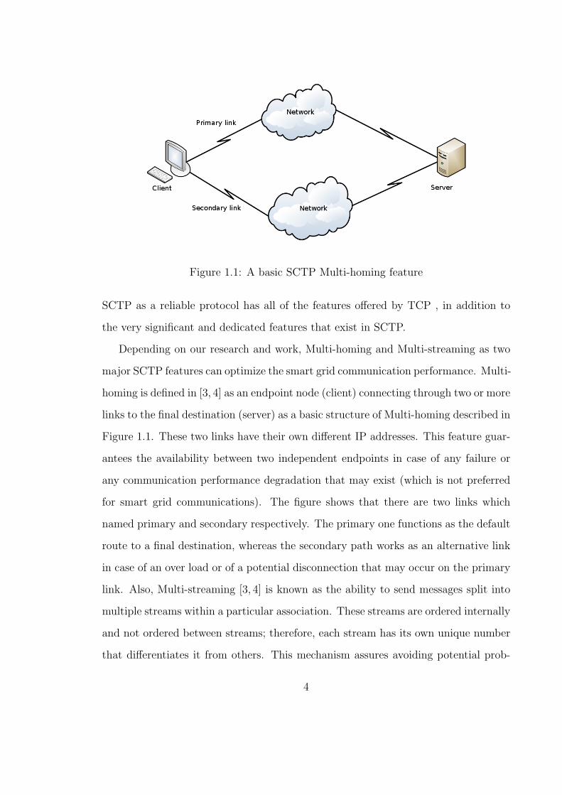
Figure 1.1: A basic SCTP Multi-homing feature
SCTP as a reliable protocol has all of the features offered by TCP , in addition to
the very significant and dedicated features that exist in SCTP.
Depending on our research and work, Multi-homing and Multi-streaming as two
major SCTP features can optimize the smart grid communication performance. Multi-
homing is defined in [3, 4] as an endpoint node (client) connecting through two or more
links to the final destination (server) as a basic structure of Multi-homing described in
Figure 1.1. These two links have their own different IP addresses. This feature guar-
antees the availability between two independent endpoints in case of any failure or
any communication performance degradation that may exist (which is not preferred
for smart grid communications). The figure shows that there are two links which
named primary and secondary respectively. The primary one functions as the default
route to a final destination, whereas the secondary path works as an alternative link
in case of an over load or of a potential disconnection that may occur on the primary
link. Also, Multi-streaming [3, 4] is known as the ability to send messages split into
multiple streams within a particular association. These streams are ordered internally
and not ordered between streams; therefore, each stream has its own unique number
that differentiates it from others. This mechanism assures avoiding potential prob-
4
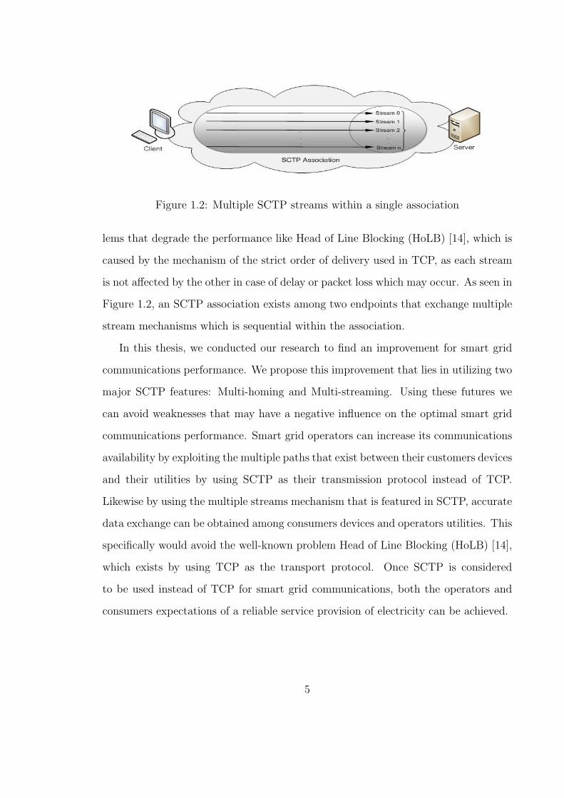
Figure 1.2: Multiple SCTP streams within a single association
lems that degrade the performance like Head of Line Blocking (HoLB) [14], which is
caused by the mechanism of the strict order of delivery used in TCP, as each stream
is not affected by the other in case of delay or packet loss which may occur. As seen in
Figure 1.2, an SCTP association exists among two endpoints that exchange multiple
stream mechanisms which is sequential within the association.
In this thesis, we conducted our research to find an improvement for smart grid
communications performance. We propose this improvement that lies in utilizing two
major SCTP features: Multi-homing and Multi-streaming. Using these futures we
can avoid weaknesses that may have a negative influence on the optimal smart grid
communications performance. Smart grid operators can increase its communications
availability by exploiting the multiple paths that exist between their customers devices
and their utilities by using SCTP as their transmission protocol instead of TCP.
Likewise by using the multiple streams mechanism that is featured in SCTP, accurate
data exchange can be obtained among consumers devices and operators utilities. This
specifically would avoid the well-known problem Head of Line Blocking (HoLB) [14],
which exists by using TCP as the transport protocol. Once SCTP is considered
to be used instead of TCP for smart grid communications, both the operators and
consumers expectations of a reliable service provision of electricity can be achieved.
5

1.2 Motivation and Objectives
While smart grid communications success depends significantly on coherence among
their peripherals, it is wise to benefit from SCTP as we propose to use its two features
Multi-homing and Multi-streaming in order to increase the chance to introduce an
accurate and dependable smart grid service. Thus, our proposal comes from some
key inducements:
• Smart grid progress relies on providing an interactive service between both the
electricity consumer meters and providers control centre of utilities.
• This interaction is a bidirectional real time data exchange that involves high
availability and fault tolerance of services between the two communicating end-
points.
• With a huge number of devices equipped with meters within houses and offices,
this exchange of data between the two parties increases the expected load on
smart grid communications [15].
• Since TCP has a strict order of delivery and there are several devices equipped
with meters communicating, it is a potential that packets drop or at least a delay
will increase the degradation of smart grid communications performance due to
the Head of Line Blocking (HoLB) trouble caused by TCP that is considered
the conventional transport protocol.
Thus, these reasons provoked us to propose SCTP to function as a candidate
transmission protocol instead of TCP for smart grid communications. Once SCTP is
used as the transmission protocol for smart grid, we argue that both the electricity
consumer and provider can benefit from using Smart Grid efficiently. Consumers
can instantly monitor and control their consumption that will be reflected on their
6

monthly electrical bills. From the electrical providers prospective, it will be easier
to sustain the electricity provided for a longer operating period, which means the
reliability is increased. Also, it will be easier to read their consumers consumption
and act accordingly in response to their demands.
1.3 Contributions
Our contribution is based on proposing SCTP to work as the default transport
protocol for smart grid communications instead of TCP in order to find a mecha-
nism that will enhance smart grid communications performance between both the
consumers and providers sides of electricity.
We conducted our experiments to evaluate whether SCTP can provide a solid
communication that smart grid can rely on and the results we discovered proved that
SCTP could be replacement of TCP in terms of delay and high availability needed for
smart grid performance optimization. We found that preference of SCTP was based
on the delay time, which is a feasible challenge to the real-time of data exchange
between the sides of consumers meters and utilities that was noticeably less than
TCP. The other preference is the high availability needed for smart grid to overcome
any interruption expected of the links among the two endpoints. Therefore there is no
doubt that the availability of smart grid communications will increase the throughput
to optimal levels needed for meters data exchanged with smart grid utility center.
Thus, once we have an electric service that is equipped with a smart grid that
uses STCP as its transport layer, we argue that the electric service is maintained
operationally and functionally under a dependable benchmark that to some extent
reflects our future expectations.
7

1.3.1 Submitted Papers
Based on the work we conducted, we have submitted the following paper:
• Majed Alowaidi, Abdulmotaleb El Saddik, and F. Richard Yu, ”Enhancing
Smart Grid Communications Performance by using SCTP Multi-homing and
Multi-streaming”, submitted to Globecom 2012 - Symposium on Selected Areas
in Communications, March 2012
1.4 Thesis Organization
In this chapter an overview of the research has been presented. Also we presented
what reasons induced us to work in this area and its targets which directed us to
propose SCTP to be the transmission protocol instead of TCP for smart grid, as well
as what contributions we think may be added to the smart grid technology. The rest
of the thesis will be as follows: In Chapter 2, literature Review and Related Works will
be introduced on the topic of communications of smart grid as well as an overview of
SCTP. The proposed solution for smart grid communications will be covered broadly
in Chapter 3. Chapter 4 will include the Simulation Results and Discussion. Chapter
5 will conclude the thesis by the Conclusions and the potential Future Work.
8

Chapter 2
Literature Review and Related
Works
2.1 Smart Grid Communications
As we previously stated, smart grid is a bidirectional intelligent electrical service
that is unlike the existing conventional electrical service that delivers a one way
and non-interactive service. From an architectural perspective, smart grid structure
encompasses three high level layers as categorized in Figure 2.1. These levels are
broken down as follows [19]:
• Physical power and Control layer: It is responsible for the core functions
such as generation, transmission and distribution of power.
• Communications layer: Functions as a bidirectional interface between utili-
ties, consumers, grid components, and operators.
• Application layer: A provision of several applications as to consumers or con-
trol systems like Advanced Metering Infrastructure (AMI), Demand Response,
9

Figure 2.1: Smart Grid Architectural levels [5]
Distributed Generation and Storage, Smart Charging of PHEVs and V2G [20],
Business and Customer Care, etc.
In this section we will focus on the Communications layer of smart grid that is
highly needed in order to run end-to-end data exchange back and forth between meters
that are called machine-to-machine (M2M) and utilities control on the operators side.
In the past, traditional grid communications runs individually in a vertical manner
where each application had its own dedicated communication infrastructure to the
final utility centre. We noticed that communications of smart grid involve a high
level of integration since this kind of communications requires multiple integrations
among smart grid applications [21]. A well-engineered model is required to guarantee
provisioning of tied communications among all smart grid nodes. Thus, nowadays
many smart grid communication architectures explain how information flows among
smart grid communications tiers and how those tiers are coupled to incorporate an
10

Figure 2.2: Smart Grid Communications Layer
integrated smart grid networking architecture.
As depicted in Figure 2.2 [5], smart grid Communications layer includes the fol-
lowing parts [22]:
• End user point holds customers premises that connect their devices with the
home network of commercial power. In this part, Home HAN, Building BAN,or
Industrial IAN Area Network exists in order to implement a group of devices
that are equipped with smart grid components.
• Advanced Smart Infrastructure AMI demarcation starts with Neighbourhood
Area Network NAN/Field Area Network FAN points that connect meters to
customers premises. AMI NAN/FAN from other side connects to the Core or
WAN.
• Substation LANs are grouped in WAN where core/metro and backhaul demar-
cation are located. This point connects several devices like SCADA [23] (refers
to Supervisory Control and Data Acquisition) inside a substation.
• LAN Network of AMI enterprises where control centre and data storage and
analysis are located.
11

As stated previously in [15] about the smart grid definition, the authors have
described smart grid communications architecture in a viewpoint model of the Euro-
pean Standards Development Process which is depicted in Figure 2.3. The Standards
consist of three basic levels or tiers that make up smart grid Communications. These
tiers are HAN, NAN, and WAN. HAN represents a communications network of appli-
ances and devices within consumers premises that have applications distributed like
smart metering and management of energy. Multiple HANs information form a NAN
that has a role of delivering HANs data to a data concentrator. Consumer’s metering
data is transported via the WAN to the Central Control of Utility whose function is
to provide billing, service management and charges of consumers electricity service.
Services like demand response or commands triggered to disable particular devices
or appliances are under the responsibility of the Distribution Control System which
is connected directly to the Utility Centre. A metering gateway is involved in this
model that connects HAN meters together, gathers meters usage information and
exchanges this information between meters or parties in which they are interested.
Authors mentioned some communications requirements for the European Model that
were concentrated in type of network range, data rate and prospective technology.
The ranges required were tens of meters for HAN, hundreds of meters for NAN and
tens of kilometres for WAN networks. Zigbee and WiFi are preferred for HAN and
NAN whilst WiMax and 3G/LTE are preferred for WAN wireless access technologies;
Power Line Communication (PLC) is common for both HAN and NAN whereas for
WAN Microwave and fiber optic are chosen as wired access technologies.
Thus, in order to make all of these communication tiers work efficiently together,
robust and integrated smart grid communications are applied. Some requirements
are addressed by [24] in order to provide at least a basic infrastructure of smart
grid communications. Vital requirements are involved in order to provide coherent
12

Figure 2.3: European Smart Grid Communications Model [15]
communications in which smart grid relies on, are listed as follows:
• Standards-based: It is needed to ensure support for the diverse set of utility
applications and to provide investment protection.
• IP network: It is based on IP to provide a diversity platform that is deliverable
to a variety of applications.
• Real-time: Smart grid needs real-time communications which are needed by
applications such as distribution automation and detection of failures.
• Scalable: It is very crucial to have a flexibility threshold of communications for
future deployment plans.
• Resilient and High Availability: A guarantee of robustness level is required
allowing systems to operate during almost all times of day.
13
• Secure: Consumption information of consumers is vulnerable to be disclosed,
therefore a very firm standard of security specifications is highly recommended.
• Broad coverage: Smart grid communications should cover a huge domain over
boundless borders allowing delivery of its services.
• Cost effective: Some expenses like CAPEX and OPEX should be put into
consideration, replacing any conventional communication infrastructure by any
Last Mile technology to have possible savings on costs or any cost made by a
competitive generation technology in future.
2.2 SCTP Overview
2.2.1 SCTP Structure View
Stream Control Transmission Protocol SCTP is considered a connection oriented
protocol running on top of IP as a connectionless Network protocol. SCTP is designed
by IETF to work by transporting PSTN signalling messages over IP networks, how-
ever it has the capability to function in a variety of applications [24]. STCP is capable
of providing a reliable transfer between SCTP peer users. It presents a connection
among users communicating in a concept of association as depicted in Figure 2.4 [4].
An association takes place through a request made by the sender and an acceptance
by the receiver. TCP as the conventional transmission protocol nowadays is reliable
as well, yet SCTP has a comprehension concept over TCP since SCTP has more
useful options which are not included even in UDP. For example, SCTP uses multiple
stream mechanisms once transmission takes place between two or more endpoints.
On the other hand, TCP only uses a single stream connection which may increase
the probability of performance degradation due to potential delay in the receiver side.
14

_____________ _____________ | SCTP User | | SCTP User | | Application | | Application | |-------------| |-------------| | SCTP | | SCTP | | Transport | | Transport | | Service | | Service | |-------------| |-------------| | |One or more ---- One or more| | | IP Network |IP address \/ IP address| IP Network | | Service |appearances /\ appearances| Service | |_____________| ---- |_____________| SCTP Node A |<-------- Network transport ------->| SCTP Node B
Figure 2.4: Two SCTP endpoints Association [4]
SCTP offers a very significant feature called Multi-homing which guarantees connec-
tion availability among communicating endpoints. With the Multi-homing feature,
two or more endpoints can have multiple links that have IP addresses among them
with one link employed as a primary link and the rest considered as secondary links
in the occurrence of an overload or failure. From a security perspective, SCTP is
featured with a four handshake mechanism when an association establishment starts.
This process which is shown in Figure 2.5 definitely increases its robustness against
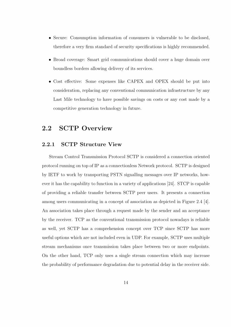
attacks like Denial of Service (DOS). When SCTP communicating parties agree to ter-
minate the ongoing association, SCTP endpoints should execute a three-handshake
process which strengthens its performance in terms of information assurance as is
shown in Figure 2.6. This process contains: SHUTDOWN, SHUTDOWN-ACK AND
SHUTDOWN-COMPLETE messages between communicating SCTP parties. Those
15

SCTP establishments and shutdown processes of connection are two of many features
that characterize SCTP over TCP. A comprehensive comparison will be presented
later on in this thesis which illustrates the SCTP features versus those in TCP as the
traditional and widespread transport protocol nowadays.
Figure 2.5: Four handshake Connection Establishment in SCTP
16
Figure 2.6: Connection Shutdown in SCTP
2.2.2 SCTP Packet Format
As other transport protocols have, SCTP has a common header and one or more
chunks which make up its packet format. A chunk is composed of either control in-
formation or user data. Single SCTP packet may have no limit of chunks unless it
doesn’t exceed the size of MTU, however control chunks such as INIT, INIT ACK,
and SHUTDOWN COMPLETE may exceed MTU size [26]. Figure 2.7 demonstrates
a common format of SCTP Packet that has a length of 32 bit as mentioned in [4]. In
the Header Format of SCTP as it is broken down in Figure 2.8, it is composed of four
fields. Port numbers of source and destination have 16 bits for each of an association
in which the association sender and receiver are both involved.
17

Figure 2.7: SCTP Packet Format [4]
Verification Tag (VT) [4], which is 32 bit long, is a tag which the sender and re-
ceiver use in order to validate the SCTP packets among them. Checksum field is one
of the most significant features that SCTP has. Since Checksum size is 32 bit and its
task is to detect the error of transmission, it establishes SCTP as more robust than
TCP, and further, UDP has 16 bit for this field. Alder algorithm of error detection
is used by SCTP. In SCTP Chunk Format, there are four fields making up Chunk
Format as described in Figure 2.9. Each chunk, whether a control or data chunk has
Chunk Type, Chunk Flags, Chunk Length and Chunk Value fields [25]. Any data be-
tween communicating SCTP peered ends is distinguished; whether a control or data,
by reading the value held in Chunk Type. Chunk type has a length of 8 bits and
the number of Chunk types whom SCTP supports currently is 13 from 255 types in
addition to the number that is used for Shutdown-Complete Chunk. The next field
is 3 bits Chunk Flag and its value depends on Chunk type.
18

Figure 2.8: SCTP Common Header Format [4]
Figure 2.9: SCTP Common Chunk Format [4]
The default value is zero [4]. Chunk Flag values for Data Chunk have three types:
U, B and E as follows:
• Flag U: When it is set that means the Chunk is not in order and the number
of streams is not valid. Also if the Chunk is fragmented, the U flag is set.
• Flag B: It is set if this flag points to the beginning of the fragment and for
un-fragmented Chunks as well.
19

• Flag E: It is set to point out to end for fragment and un-fragmented Chunk
should have this flag set as well.
The size in bytes of Chunk Type, Chunk Flags, Chunk Length and Chunk Value is
indicated in the Chunk Length field, which its length is 16 bits. The last field in the
SCTP Chunk Format is the Chunk Value that has the real information transmitting
in a Chunk. The value in this field is adaptable due to the Chunk Type. Table 2.1
shows a complete list of the SCTP Chunk Types as defined in RFC4960.
20

Table 2.1: SCTP Common Chunk Format
ID Value Chunk Type
0 Payload Data (DATA)
1 Initiation (INIT)
2 Initiation Acknowledgement (INIT ACK)
3 Selective Acknowledgement (SACK)
4 Heartbeat Request (HEARTBEAT)
5 Heartbeat Acknowledgement (HEARTBEAT ACK)
6 Abort (ABORT)
7 Shutdown (SHUTDOWN)
8 Shutdown Acknowledgement (SHUTDOWN ACK)
9 Operation Error (ERROR)
10 State Cookie (COOKIE ECHO)
11 Cookie Acknowledgement (COOKIE ACK)
12 Reserved for Explicit Congestion Notification Echo (ECNE)
13 Reserved for Congestion Window Reduced (CWR)
14 Shutdown Complete (SHUTDOWN COMPLETE)
15 to 62 reserved by IETF
63 IETF-defined Chunk Extensions
64 to 126 reserved by IETF
127 IETF-defined Chunk Extensions
128 to 190 reserved by IETF
191 IETF-defined Chunk Extensions
192 to 254 reserved by IETF
255 IETF-defined Chunk Extensions
21
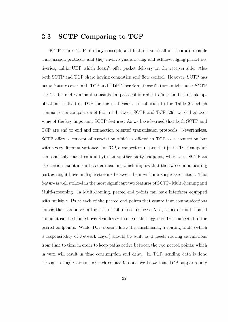
2.3 SCTP Comparing to TCP
SCTP shares TCP in many concepts and features since all of them are reliable
transmission protocols and they involve guaranteeing and acknowledging packet de-
liveries, unlike UDP which doesn’t offer packet delivery on the receiver side. Also
both SCTP and TCP share having congestion and flow control. However, SCTP has
many features over both TCP and UDP. Therefore, those features might make SCTP
the feasible and dominant transmission protocol in order to function in multiple ap-
plications instead of TCP for the next years. In addition to the Table 2.2 which
summarizes a comparison of features between SCTP and TCP [26], we will go over
some of the key important SCTP features. As we have learned that both SCTP and
TCP are end to end and connection oriented transmission protocols. Nevertheless,
SCTP offers a concept of association which is offered in TCP as a connection but
with a very different variance. In TCP, a connection means that just a TCP endpoint
can send only one stream of bytes to another party endpoint, whereas in SCTP an
association maintains a broader meaning which implies that the two communicating
parties might have multiple streams between them within a single association. This
feature is well utilized in the most significant two features of SCTP- Multi-homing and
Multi-streaming. In Multi-homing, peered end points can have interfaces equipped
with multiple IPs at each of the peered end points that assure that communications
among them are alive in the case of failure occurrences. Also, a link of multi-homed
endpoint can be handed over seamlessly to one of the suggested IPs connected to the
peered endpoints. While TCP doesn’t have this mechanism, a routing table (which
is responsibility of Network Layer) should be built as it needs routing calculations
from time to time in order to keep paths active between the two peered points; which
in turn will result in time consumption and delay. In TCP, sending data is done
through a single stream for each connection and we know that TCP supports only
22

a firm order of delivery, which means that delivery of packets should consider the
order of a packets sent by sending side. Thus in the case of packet delay or drop this
often results in consecutive packets being delayed and not delivered to the upper layer
until retransmission of the dropped packets has been issued to the sender. On the
other hand, SCTP possesses the mechanism of Multi-streaming within an association.
Streams inside the association are ordered and have a unique number, whereas the
order is not necessary between associations. This feature of SCTP makes packets in
the case of any other packets being delayed at the receivers side not buffered, and thus
will be passed on to the upper layer. The SCTP Multi-streaming feature can avoid
the well-known TCP problem, Head-of-Line Blocking HoLB, by unlinking the pack-
ets processing at the receiving side by any undelivered packets in the order which
they were used on the sending side. Instead of this, the delivery order only takes
place within a single association. In terms of error detection, SCTP features more
robustness than TCP since the Checksum field in SCTP is 32 bit whereas in TCP
it is half of SCTPs. TCP uses a three handshake mechanism in order to establish a
connection which is vulnerable to potential attacks such as Denial of Service (DOS).
This is caused by requests of spoof connection setups, whereas in SCTP there is a
four handshake mechanism of association establishment which can avoid the (DOS)
problem mentioned above by using a cookie called INIT-ACT Chunk sent back from
a server that has verification information about the real sender involved in the asso-
ciation [27]. There is no doubt that this four-handshake mechanism of SCTP has a
positive influence on real time applications or services that seek stability. In SCTP
there is a field called Verification Tag (VT) [4] used to identify each association in
which SCTP packets belong. This tag distinguishes SCTP versus TCP in terms of
reliability since all associations are scheduled appropriately.
SCTP can handle two paths or more operating together simultaneously between
23

Table 2.2: A comparison of SCTP and TCP
Service/Feature SCTP TCP
Connection-oriented yes yes
Full duplex yes yes
Reliable data transfer yes yes
Partial-reliable data transfer optional no
Ordered data delivery yes yes
Unordered data delivery yes no
Flow control yes yes
Congestion control yes yes
ECN capable yes yes
Selective ACKs yes optional
Preservation of message boundaries yes no
Path MTU discovery yes yes
Application PDU fragmentation yes yes
Application PDU bundling yes yes
Multi-streaming yes no
Multi-homing yes no
Protection against SYN flooding attacks yes no
Allows half-closed connections no yes
Reachability check yes yes
Psuedo-header for checksum no(uses vtags) yes
24
peered end points. This concept is achieved by using a feature called Concurrent
Multiple Transfer (CMT) [4, 18] which enables SCTP to have multiple independent
paths between two end nodes . This supports Multi-homing, where these paths share
sending data among them concurrently by splitting traffic to be distributed through
these paths [28].
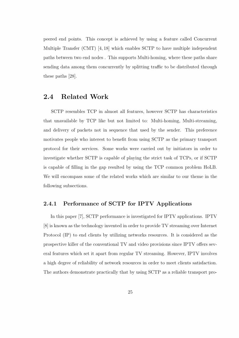
2.4 Related Work
SCTP resembles TCP in almost all features, however SCTP has characteristics
that unavailable by TCP like but not limited to: Multi-homing, Multi-streaming,
and delivery of packets not in sequence that used by the sender. This preference
motivates people who interest to benefit from using SCTP as the primary transport
protocol for their services. Some works were carried out by initiators in order to
investigate whether SCTP is capable of playing the strict task of TCPs, or if SCTP
is capable of filling in the gap resulted by using the TCP common problem HoLB.
We will encompass some of the related works which are similar to our theme in the
following subsections.
2.4.1 Performance of SCTP for IPTV Applications
In this paper [7], SCTP performance is investigated for IPTV applications. IPTV
[8] is known as the technology invented in order to provide TV streaming over Internet
Protocol (IP) to end clients by utilizing networks resources. It is considered as the
prospective killer of the conventional TV and video provisions since IPTV offers sev-
eral features which set it apart from regular TV streaming. However, IPTV involves
a high degree of reliability of network resources in order to meet clients satisfaction.
The authors demonstrate practically that by using SCTP as a reliable transport pro-
25

tocol which has a mechanism that enhances the IPTV applications performance, this
in turn leads to supporting IPTV applications efficiency more than TCP and UDP.
We think that this conducted research is similar to ours because both smart grid com-
munications and IPTV applications depend on real time streaming of data which is
supported by SCTP via its effective features such as Multi-streaming, and by offering
the flexibility of two options of delivery. Also, having a method consisting of interac-
tive exchange of data and control between end users and IPTV providers involves an
uninterrupted connection which may be offered by SCTP due to unexpected networks
situations.
2.4.2 Measurement-Based Analysis of HoLB for SIP over
TCP
We have chosen this paper indicated in [9] because the authors measured SIP,
which is a signalling protocol like SCTP, through a method which shows the suffering
of SIP from HoLB, caused by the TCP order of delivery style. SIP as mentioned in
RFC 3261 [10] is a session initiation protocol and a signalling protocol used to create,
maintain, and close a connection which occurs between two end points. SIP is located
in the application layer. Authors of this paper argue that using SCTP as the transport
protocol for SIP instead of TCP or UDP depends on their encouraging results. Their
recommendation is based on high loss links or congestion that is directly correlated
with high latency. Continually, in RFC4168 [11], similar draft that is proposed by
authors to use SCTP as the mechanism of transport between two end points of SIP
protocol. Their assumption comes up depending on the significant of SCTP features
(two of which will be described intensively in Chapter 3) that might tolerate the
exchange of huge amounts of data within SIP entities.
26
2.4.3 Performance Evaluation of a Transport Layer Solution
for Seamless Vertical Mobility
Wireless fields benefit from SCTP as well since modifications can be made in the
transport layer with no effect on any layers below it. In [12] a solution has been
presented in order to provide a smooth heterogeneous mobility for a mobile client
such as a mobile host (MH) which roams through different network interfaces. MH
as defined in [13] represents a host or router that is a member in ad hoc network(s).
The authors argue that this improvement can provide a better handover and less
delay by exploiting SCTP multihoming. Their scheme proposes new paths which
are prepared for MH while roaming, while still keeping old paths available. Thus
this proposal aims to mitigate latency while switchover, which in its turn helps to
have higher bandwidth. Continually, the authors also claim that their addressable
solution is able to offer a variety of user preferences and context awareness. We have
intentionally chosen this work due to its theme that proves the advantages of SCTP
in order to improve networks performance without any modifications on underlying
layers of the OSI model.
2.5 Summary
In this chapter, we have seen that unlike the traditional electric grid, smart grid
is intended to have the initiation in order to provide an intelligent reaction in several
situations for both consumers and operators in need of electricity. These situations
include but are not limited to instantaneous consumption monitoring, responding
to predefined control actions, self-healing, reducing of Co2 emission consumption,
and many advantages required by both electricity consumers and providers. Smart
grid communications require an integrated and tied level of its tiers in order to have
27

dependable smart grid services to final consumers. SCTP as a reliable transport
protocol has high potential to function instead of TCP. SCTP and TCP mutually
share significant features such as flow and congestion control, and order of delivery.
However SCTP is preferred over TCP due to much of the advancements that SCTP
possesses. Among several SCTP features, Multi-homing and Multi-streaming are
very important factors influencing SCTP positively over TCP. The next chapter will
discuss the proposal we argue for smart grid communications.
28

Chapter 3
Proposed Smart Grid
Communications Using SCTP
Multi-homing and Multi-streaming
Since smart grid is still in its infancy we argue that communication between the
SmallOffice/HomeOffice SOHO Gateway and the furthest end point that represents
utility center of smart grid is a big concern. This challenge needs more attention
since each SOHO party has many devices or appliances equipped with smart meters
that exchange data back and forth all of the time among meters and between meters
and the utility center of smart grid. Thus, the exchange of huge data will impact
the communication link traffic causing the probability of disconnection or at least
degradation in smart grid performance is bigger. We propose obtaining the benefits
of SCTP characteristics by utilizing its two major features: Multi-homing and Multi-
streaming. We suggest that these two SCTP features help smart grid operators
overcome the communication challenge as one of three challenges facing smart grid
that mentioned in [15].
29

In the next two consecutive sections, we will examine the inducements of choosing
these SCTP features that we suppose to solve smart grid communications challenge.
3.1 Redundant Paths by Multi-homing
The multi-homing feature that is offered by SCTP has a vital concept of providing
multiple and redundant IP addresses for each side of the communicating endpoints.
One of these paths is considered as a primary and the rest are considered secondary
(alternative) paths. Thus, one side, which is considered the transmitter side, is capa-
ble of switching over to an alternative IP in the case that failure or overload may occur
during undergoing of communications. These redundant paths are very helpful in in-
creasing throughput and operating time. Furthermore, in general it would enhance
all applications performance. For smart grid communications as it is our theme, it
is crucial to have a solid and trustworthy transport protocol in order to provide a
well tight and accurate electricity service between consumers’ meters and utilities or
central control departments. The next two subsections will include the reasoning as
to why we argue that TCP is not favourable as the core transport protocol for smart
grid communications. We argue that SCTP is capable of functioning alternatively of
TCP between the gateway located in HAN and utilities located in the furthest point
of smart grid communications.
3.1.1 TCP Lack of Paths Management
In OSI Reference Model [16, 17] , we have learned that in the Transport Layer
where the Transmission Control Protocol (TCP) resides , TCP is responsible for
the connection establishment and termination of end-to-end communications. It is
unique, reliable, and connection-oriented among several protocols of the Transport
30
Layer. Nevertheless, since TCP is the dominant protocol for the Internet and private
networks, it doesn’t possess the concept of managing paths or links within a variety of
networks (borders). Although TCP has very crucial mechanisms such as: congestion
window (CWND) and flow control of such a connection, retransmission method in
case of packet drop or time expiration (TTL), and several features to maintain a
connection, unfortunately these TCP features can’t handle links management due
to foreseeable paths status. Such providers of applications and services that need
continuous operating times will claim service instability. For example, critical health s
need uninterrupted communications of their medical peripherals that will be reflected
on patients’ health. Also, natural disasters s emphasize keeping their sensors, alarms
and monitoring components functioning and online at all times. For smart grid, it is
necessary to assure all of its communication tiers are linked and exchanged accurately
to their data that is analyzed from consumers’ meters. SCTP receives the benefit of
Multi-homing by using a method that monitors a status of other destinations’ paths
in which a sender is involved in a connection. This feature is called Heartbeat that
checks the reachability of the far peer links [3, 4].
We believe that this management of smart grid communications can be achieved
by using SCTP Multi-homing between communicating peered endpoints.
3.1.2 Fault Tolerance by Multipath
We realise from the last subsection that TCP is not suitable to fulfil management of
multiple paths in order to guarantee providing a high availability and non-interruption
of smart grid service. Due to millions of applications transactions that are being un-
dergone nowadays, an overload definitely will come up from communications infras-
tructure. TCP as a reliable transmission protocol can solve traffic problems however
such interruption of routes or links of a connection is out of TCPs role. It is well
31
known that most companies are concerned about securing their information or that
of their costumers by installing fault tolerant and high availability firewalls in front
of their own private networks to avoid any feasible attacks. Similarly, there are some
vital missions or services in the commercial or health fields which cannot tolerate
or allow for any disconnection periods even if there are five 9s after 99 percent of
interruption. Thus, It is crucial to possess a robust communications tool, which is
not offered in TCP as a shortcoming of its design against potential fault events. We
believe that SCTP has an adaptive failover mechanism that can assure a smooth
change of traffic path to any of alternative paths in case of links being down, overload
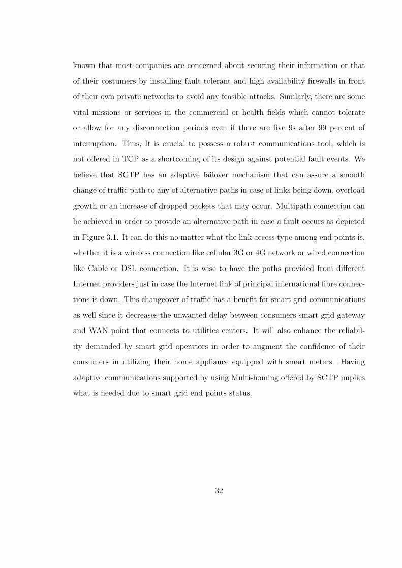
growth or an increase of dropped packets that may occur. Multipath connection can
be achieved in order to provide an alternative path in case a fault occurs as depicted
in Figure 3.1. It can do this no matter what the link access type among end points is,
whether it is a wireless connection like cellular 3G or 4G network or wired connection
like Cable or DSL connection. It is wise to have the paths provided from different
Internet providers just in case the Internet link of principal international fibre connec-
tions is down. This changeover of traffic has a benefit for smart grid communications
as well since it decreases the unwanted delay between consumers smart grid gateway
and WAN point that connects to utilities centers. It will also enhance the reliabil-
ity demanded by smart grid operators in order to augment the confidence of their
consumers in utilizing their home appliance equipped with smart meters. Having
adaptive communications supported by using Multi-homing offered by SCTP implies
what is needed due to smart grid end points status.
32

Figure 3.1: Multipath redundant using SCTP Multi-homing
3.2 Improve Performance with Multi-streaming
As we have viewed previously, SCTP has two major factors that make it in some
way better than TCP; one of which is Multi-streaming as a method of transmitting
data into an SCTP association. As mentioned in [3, 4], an SCTP association is “a
protocol relationship between SCTP endpoints composed of the two SCTP endpoints
and protocol state information”. Each association has multiple independent streams.
These streams inside an association are unidirectional and in sequence order. How-
ever, it is possible that associations may not be in the right sequence in which it
was sent. Each association is identified by a Transmission Sequence Number (TSN)
and each stream has a sequence number called the Stream Identifier (SI)to be distin-
guished between multiple streams. These two parameters are demanded in order to
provide the uniqueness of each data chunk. To discriminate fragmented data into a
stream, Stream Sequence Number (SSN) is required. Figure 3.2 explains how frag-
mented data is created into multiple streams.
33

Figure 3.2: TSN, SI and SSN for SCTP Multiple-steams [29]
3.2.1 HoLB Problem Scenario in TCP (makes it challenge
for Smart Grid)
Although TCP is a reliable transmission protocol that acknowledges every packet
delivered, it has a problem regarding the order way used in receiving side. TCP uses
a firm order of delivery which obligates any delivered packets at the receiving side to
be pending or buffered until any delayed packets arrive or retransmission of dropped
packets is successful. This mechanism demonstrates a common TCP problem, which
is Head of Line Blocking (HoLB). This TCP problem is described in Figure 3.3 (a)
and (b) respectively. In (a) an end-to-end TCP connection has been established
between two endpoints; this connection has a sequence of packets transmitting in a
way that TCP only supports. Once one of these streams gets lost (packet 1), the
successive packets will be influenced by this drop and buffered in a buffer pending
until the lost one is retransmitted and then all of the packets waiting will be delivered
to the next layer. Even if there are multiple connections, the effect will be similar as
depicted in (b) however other connections have their own order. In TCP connection
34
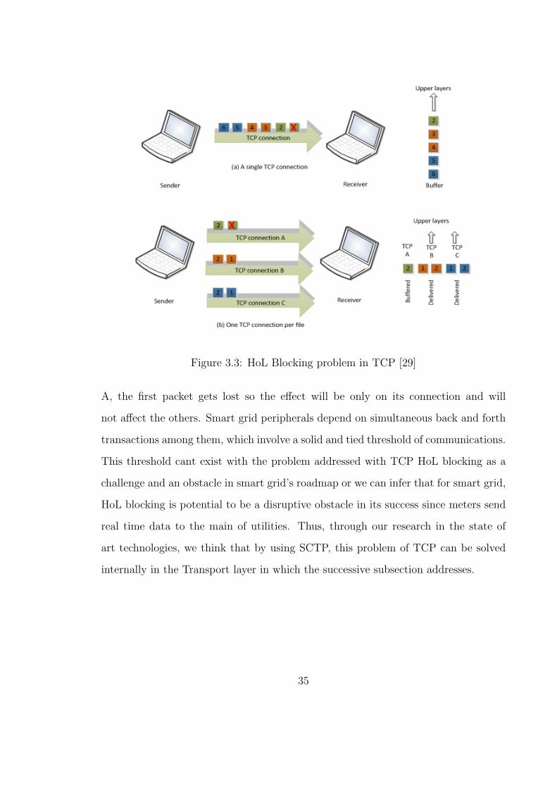
Figure 3.3: HoL Blocking problem in TCP [29]
A, the first packet gets lost so the effect will be only on its connection and will
not affect the others. Smart grid peripherals depend on simultaneous back and forth
transactions among them, which involve a solid and tied threshold of communications.
This threshold cant exist with the problem addressed with TCP HoL blocking as a
challenge and an obstacle in smart grid’s roadmap or we can infer that for smart grid,
HoL blocking is potential to be a disruptive obstacle in its success since meters send
real time data to the main of utilities. Thus, through our research in the state of
art technologies, we think that by using SCTP, this problem of TCP can be solved
internally in the Transport layer in which the successive subsection addresses.
35

3.2.2 Multi-Streaming Mechanism in SCTP
SCTP has a very useful and realistic feature called Multi-streaming. This feature
is in opposition to the single stream bytes mechanism used by TCP which causes the
aforementioned problem HoL Blocking. Multi-streaming obtained its name through
SCTP being derived from this dominated feature. SCTP is categorised as a message
oriented protocol, which signifies a sequence of messages transmitted instead of the
single stream method used by TCP. Each stream in an SCTP association possesses
identifiers that contain TSN, SI, and SSN; each identifier holds a value which repre-
sents a portion of a Chunk identity. The most important one is SI, Stream Identifier,
which characterises a stream from other streams that belong to different Chunks. SI,
TSN, and SSN are used only for data chunks. If a message needs to be fragmented
into multiple streams, which means its size exceeds the MTU size (for example 1500
bytes for Ethernet), the streams should have sequence numbers to be distinguished
within that stream, which means each stream is assigned a unique SSN. When using
multiple streams from multiple associations, the order of delivery is not considered
however all streams within an association should be sequenced in delivery. The effect
is only applied on messages inside a single stream, not on the whole streams. A
concise explanation is shown in Figure 3.4 that presents two diagrams of an SCTP
association of a single stream and multiple streams which occur in the SCTP envi-
ronment. In (c) where an SCTP association possesses three streams, each stream
has its own fragmented messages, and applies a delivery sequence; meaning that the
delivery on the receiving side is affected internally on the stream level. Therefore, any
delay or retransmission on such streams doesn’t affect other streams. For Example,
stream 0 has two fragments SSN 2/0 and 2/1 respectively; 2/0 has lost so the SSN in
the same stream will be buffered until the lost one is retransmitted. However, SSNs
from other streams (stream 1 and 2) inside the current association will be delivered
36
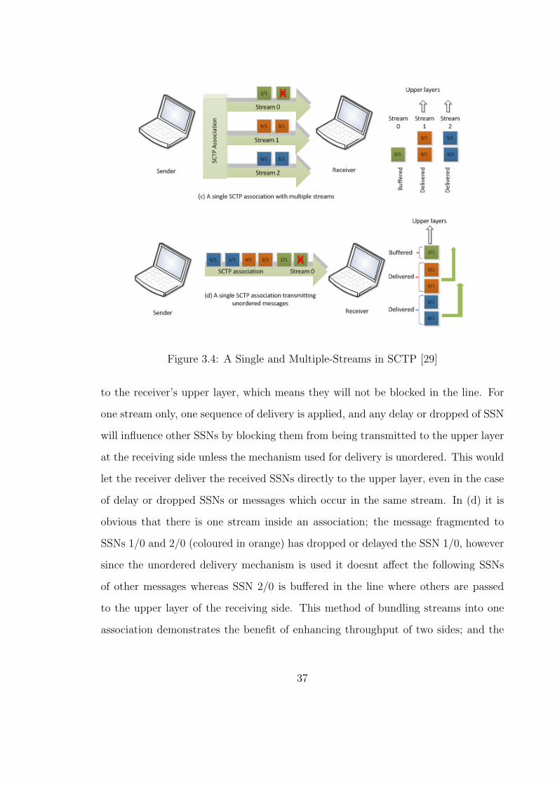
Figure 3.4: A Single and Multiple-Streams in SCTP [29]
to the receiver’s upper layer, which means they will not be blocked in the line. For
one stream only, one sequence of delivery is applied, and any delay or dropped of SSN
will influence other SSNs by blocking them from being transmitted to the upper layer
at the receiving side unless the mechanism used for delivery is unordered. This would
let the receiver deliver the received SSNs directly to the upper layer, even in the case
of delay or dropped SSNs or messages which occur in the same stream. In (d) it is
obvious that there is one stream inside an association; the message fragmented to
SSNs 1/0 and 2/0 (coloured in orange) has dropped or delayed the SSN 1/0, however
since the unordered delivery mechanism is used it doesnt affect the following SSNs
of other messages whereas SSN 2/0 is buffered in the line where others are passed
to the upper layer of the receiving side. This method of bundling streams into one
association demonstrates the benefit of enhancing throughput of two sides; and the
37

Figure 3.5: SCTP Multi-streaming with in order delivery [30]
most important remains in solving the trouble of HoL blocking that exists in TCP.
More detailed graph for Multi-streaming can be seen in Figure 3.5 which uses the
sequence delivery mechanism of a multiple stream association. There are four SCTP
streams combined in that association. Each stream has its buffer in the receiver side
of its transport layer. As we have discussed that SCTP supports delivery of not
in sequence method in addition to the default one, which is the delivery of in the
sequence of packets whom a sender is used to send. It is clear that some streams in
the graph have similar SSNs as seen in streams 1 and 2 that have SSN 11 and SSN
12, yet due to the nature of the Multi-streaming feature, a stream sequence number
should be unique inside the streams not in between. We can observe that SSNs 11
and 12 are exist in both streams 1 and 2 however SSNs 10, 11 and 12 in stream 2 are
buffered because SSN 9 is lost which in turn affects other sequences being buffered
38

until the lost SSN 9 is retransmitted. Also, in stream 4 due to a missing of message
with SSN 22, this will affect the following one which is SSN 23 to be held until
delivery of SSN 22 to the upper layer is done, and then the buffered one (SSN 23) is
handed to the next layer. It is important to be aware that any delay or packet drop
on a stream has an effect on its internal messages whether the delivery method used
is in order or not. Through our research and simulation conducting we argue that
smart grid operators might suffer by using TCP as their transport protocol. Since
we found evaluations of SCTP delay, throughput, and availability are very critical
factors that have an impact on smart grid communications, it is wise that electricity
providers direct their attention toward utilizing SCTP as its transmission protocol
for end to-end communications of smart grid.
3.3 Summary
We have discussed in this chapter the suggested solution of SCTP as a transport
protocol for smart grid communications, depending on the evaluation conducted in
ns2, Network Simulator version 2.34 [31], in addition to the research we have carried
out on state of the art smart grid challenges regarding communication discipline.
The proposed solution was essentially built on the weaknesses that we discovered in
TCP architecture in terms of delays as a result of HoL blocking, throughput, and
availability since TCP is considered for smart grid communications. SCTP is robust
against any feasible failure that may occur on a link due to overloading traffic or an
unpredicted disconnection which exists in TCP. Smart grid nature’s involves huge
traffic and real time data exchanged between its meters from the customer’s side and
central utilities control s. Multi-homing and Multi-streaming as two significant SCTP
features have the potential of playing a major role in smart grid communications; we
argue that this might happen after we did some evaluations of SCTP Multi-homing
39

and Multi-streaming in our testing against TCP. These tests and its results of both
SCTP and TCP evaluations are broadly covered in the consecutive chapter.
40

Chapter 4
Simulation Results and Discussion
In this chapter (where the entirety of our work was conducted), we will review the
current and most common simulation tools used for networks simulation, then we will
analyze the tool which we relied upon for our testing ns2 [31] including what it is and
why it was chosen. The criteria that motivated us to evaluate SCTP against TCP
will be covered extensively and it will be followed by the results that we discovered.
4.1 Overview of Simulation Tools
Upon a literature review, we realized that we should evaluate whether or not SCTP
does truly meet the requirements that can address smart grid communications chal-
lenge. Evaluation of SCTP led us to search current simulation softwares dedicated
to networks as the environment of product testing. Network simulation is a software
which imitates network environments in a way that researchers focus on testing spe-
cific measurements. Before we started evaluating our theme, we should have gone over
simulation tools that were offered to the public. There are two general classifications
of simulation tools: open source tools and commercially owned tools. Open source
tools are free to utilize whereas commercial simulation tools require users to pay for
41
its usage. An open source simulation is regularly free of charge to use, and is not
supported or supervised by an official reference of an academic institution. However,
since its source is explicit to end users, it can be developed by academic institutions
or individuals and then spread to communities free of charge. On the other hand,
simulation tools under commercial supervisory have both positive and negative sides.
Since a company owns a network simulation and seeks profit, it hides the source files
from public, so any structure development of the simulation software is not allowed
to be seen by others that make it inflexible to researchers’ demands. However, some
networks simulation software companies offer support for their customers by offering
already created packages and samples of network components by updating simula-
tion softwares versions and answering any customers queries. Also some firms allow
users to add their needs of packages once those users own a licence of the simulation
such as OpNet which will be discussed later. OpNet [33], which refers to Optimized
Network Engineer Tools, has one of the best commercial networks simulations (Op-
Net Modular) that contains a detailed network database which provides solutions to
model, simulate and analyse a diversity of wired and wireless networks. It supports
many protocols and models that exist nowadays like TCP, BGP, IPVs, MPLS, UMTS,
WiMAX, WiFi, .etc. Unfortunately it doesnt support SCTP as a key weakness of
OpNet, which led us to seek another tool that meets our principal requirement.
There are several network commercial simulations that exist nowadays like Net-
Disturb [34], QualNet [35], etc. Whereas open source softwares of network simulations
are open to public to use, develop, and make major changes, some named versions
were made by institutions whom they modify. Network Simulator ns2 [31], which has
been used in our theme evaluation and will also be covered in the next section, is a
well-known open source and free simulation, and widely utilized in the academic field.
In addition to ns2, there are some free of charge simulators such as OmNet++ [36, 37],
42
SSF [38, 39], PDNS [40], GtnetS [41], M5 [42, 43] and a lot of free network simula-
tions that don’t involve users to pay expenses to own or develop. However, they
vary in some major and minor features. The table shown in 4.1 summarizes the key
differences between OpNet as the widely used commercial network simulation and
OmNet++ and ns2 as the two prominent open source network simulation softwares
which are free of charge. However, OpNet Modular has two distributions; one for
commercial use, and the other for academic and research utilization that will be com-
pared in the table [44]. Each simulation has its specific features that distinguish it
from others, however, we chose to conduct our measurements and assessments with
ns2 for reasons that will be covered in the following overview subsection.
4.1.1 Tool Used for Simulation
After introducing an overview of the simulation tools used to test and study some
parameters of behaviour needed for specific purposes, we will cover the network sim-
ulation tool ns2, especially ns2.34, which was chosen to carry out the measurements.
This coverage will include the cause that induces us to choose ns2 among several
networks simulations; the structure and components of ns2 and its strengths and
drawbacks will be covered as well. Network Simulator ns [31, 32], ns2 is the 2nd ver-
sion as the extension 2.34 used in our tests is a network simulator driven by events.
It was established in 1989 as a variant of Real [45] network simulator, which was
envisioned in packet switched data networks in order to evaluate congestion and traf-
fic flow control of dynamic behaviour, and later on was developed completely and
gradually through consecutive years. DARPA [46] developed ns in 1995 through
supporting ns in its project VINT (Virtual InterNetwork Testbed) [47] through a
cooperative work between LBL, Xerox PARC UCB and USC/ISI. NS is currently
supported via DARPA by using SAMAN [48] and via NSF by using CONSER [49] in
43

Table 4.1: Key differences between OpNet, OmNet++ and NS2
Open source Network simulations Commercial Net-
work simulation
Ns2 OmNet++ OpNet Modular
Programming
environment
C++ and OTcl C++ C++
Graphical in-
terface(GUI)
No Only CLI Yes Yes
Targeted for Academic re-
search
Academic re-
search
Academic re-
search and
commercial
Support type By individuals,
limited
Official firm,
moderate
Official firm,
professional
Cost per
download
Free for all pub-
lic
Free for non-
profit use only
Cost needed and
expensive
Simplicity (us-
ability)
Not simple since
no
Simple since it
has GUI and
Simple since it
has many
support and no
GUI
still has evolving
documentation
models to create
a whole topology
and GUI
SCTP support Full support Limited support Not yet
Key
-No documenta-
tion
-Insufficient doc-
umentation
-Expensive
product
weaknesses -No obvious sep-
aration between
-Reporting is
not enough
-Online sequen-
tial analysis of
C++ and OTCL output data is
not supported.
44
order to cooperate with other researches such as ICSI Networking group [50] in Berke-
ley University. Moreover, the contributions achieved for ns are made by researchers
from both academic as well as industry fields, for example, the University of Cal-
ifornia at Berkeley (UCB) as Daedalus project, Carnegie Melon University (CMU)
as Monarch Projects and Sun Microsystems. There are many manual versions of ns
that have been created by different firms. Although these manuals are not unified
in their contents, the most knowledgeable ones, depending on their popularity, are
The VINIT Project [51] and Introduction to Network Simulator NS2 [52]. After we
have reviewed a summary of NS history, we will then look at its structure- figuring
out the most important aspects of NS. NS is an object oriented simulation software
that was written by C++ and OTCL [57]. OTCL is a free Object Tool Command
Language that represents a fronted interpreter of NS, whereas most network protocol
models were written by C++ which plays as the NS compiler. Thus, the simulator
has two hierarchies, which build its structure, C++ and OTCL that are closely linked
together. A correspondence of one-to-one is viewed between the two classes from a
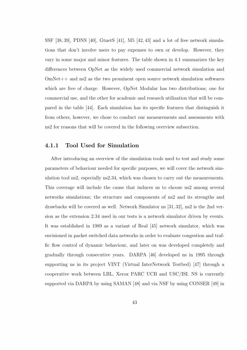
user viewpoint. Figure 4.1 shows the basic structure of ns2 two class’s hierarchy.
Thus, why there are two languages that construct ns2? This structure consisting
of two languages makes all ns versions unique among other simulations. As mentioned
previously, NS2 structure is built on two languages [52], whereas C++ is used to run
the simulation compilation, OTcl’s function is used to create and configure a network
(node, link, packet, queue, etc.) as an interpreter. Since each language has both
good and undesirable aspects, they are combined together to construct ns. C++ can
quickly compile ns body source even if the source is large, yet modifying a parameter
in a Tcl code involves compiling the ns body and linking it with OTcl respectively.
Whereas in OTcl which is only an interpreter of all ns distributions, any modifi-
cation does not involve a compilation, however, OTcl doesn’t deal with transferring
45
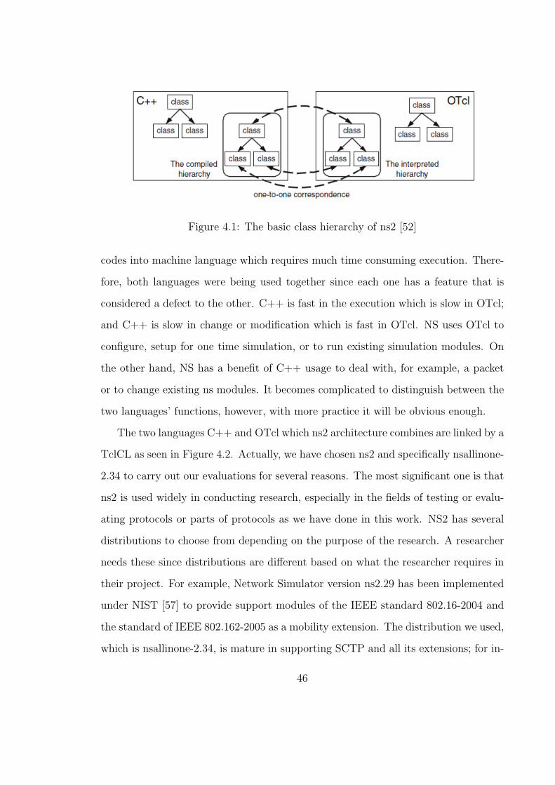
Figure 4.1: The basic class hierarchy of ns2 [52]
codes into machine language which requires much time consuming execution. There-
fore, both languages were being used together since each one has a feature that is
considered a defect to the other. C++ is fast in the execution which is slow in OTcl;
and C++ is slow in change or modification which is fast in OTcl. NS uses OTcl to
configure, setup for one time simulation, or to run existing simulation modules. On
the other hand, NS has a benefit of C++ usage to deal with, for example, a packet
or to change existing ns modules. It becomes complicated to distinguish between the
two languages’ functions, however, with more practice it will be obvious enough.
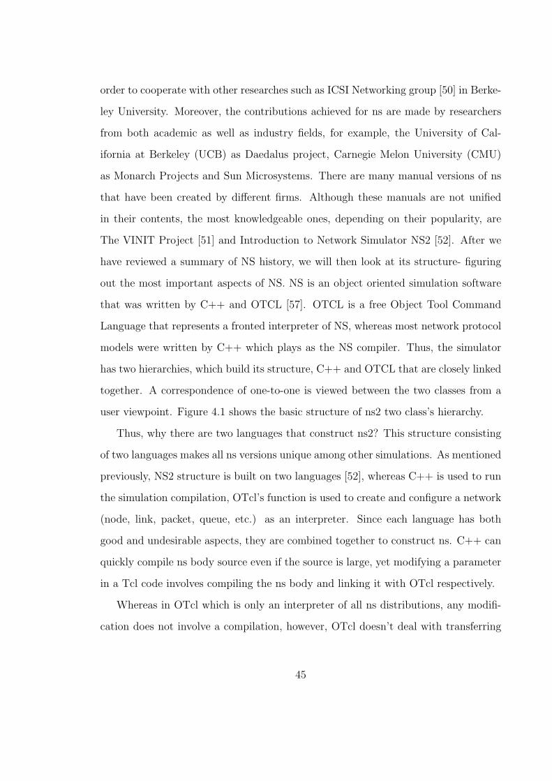
The two languages C++ and OTcl which ns2 architecture combines are linked by a
TclCL as seen in Figure 4.2. Actually, we have chosen ns2 and specifically nsallinone-
2.34 to carry out our evaluations for several reasons. The most significant one is that
ns2 is used widely in conducting research, especially in the fields of testing or evalu-
ating protocols or parts of protocols as we have done in this work. NS2 has several
distributions to choose from depending on the purpose of the research. A researcher
needs these since distributions are different based on what the researcher requires in
their project. For example, Network Simulator version ns2.29 has been implemented
under NIST [57] to provide support modules of the IEEE standard 802.16-2004 and
the standard of IEEE 802.162-2005 as a mobility extension. The distribution we used,
which is nsallinone-2.34, is mature in supporting SCTP and all its extensions; for in-
46

Figure 4.2: The ns basic architecture of C++ and OTcl [52]
stance, Concurrent Multiple Transfer(CMT) [18, 58] and HEARTBEAT [3, 4] as two
of SCTP agents. In addition, most researchers highly recommend using this version
of NS (nsallinone-2.34). Overall, NS is capable of functioning in Windows by using
Cygwin [59] and any distribution of Linux, however we truly recommend using Linux
especially for the distribution of Ubuntu whom we found the most convenient one to
run NS.
NS supports many packages (in addition to SCTP) of transport layer protocols
like TCP, UDP and applications like FTP, Telnet and CBR. Also, it does support
several queues management such as DropTail, RED and CBQ. For the simplicity
of visualizing a network topology, NS comes equipped with an extension of TCL
which is Tcl/TK [55, 56], Tool Command Language that has an extension of Tool kit
to provide graphical programming tool called Network Animator (NAM) [60] that
animates the traffic generated by NS scripts, thus NAM helps in understanding the
simulation topology and how traffic is streaming simultaneously into that topology.
NS generates a trace file, which is tailed by (.tr), that is involved in recording all
network information transactions including topology creation. Tables 4.2 and 4.3
respectively show the normal format of a standard trace file for both SCTP [53] and
47
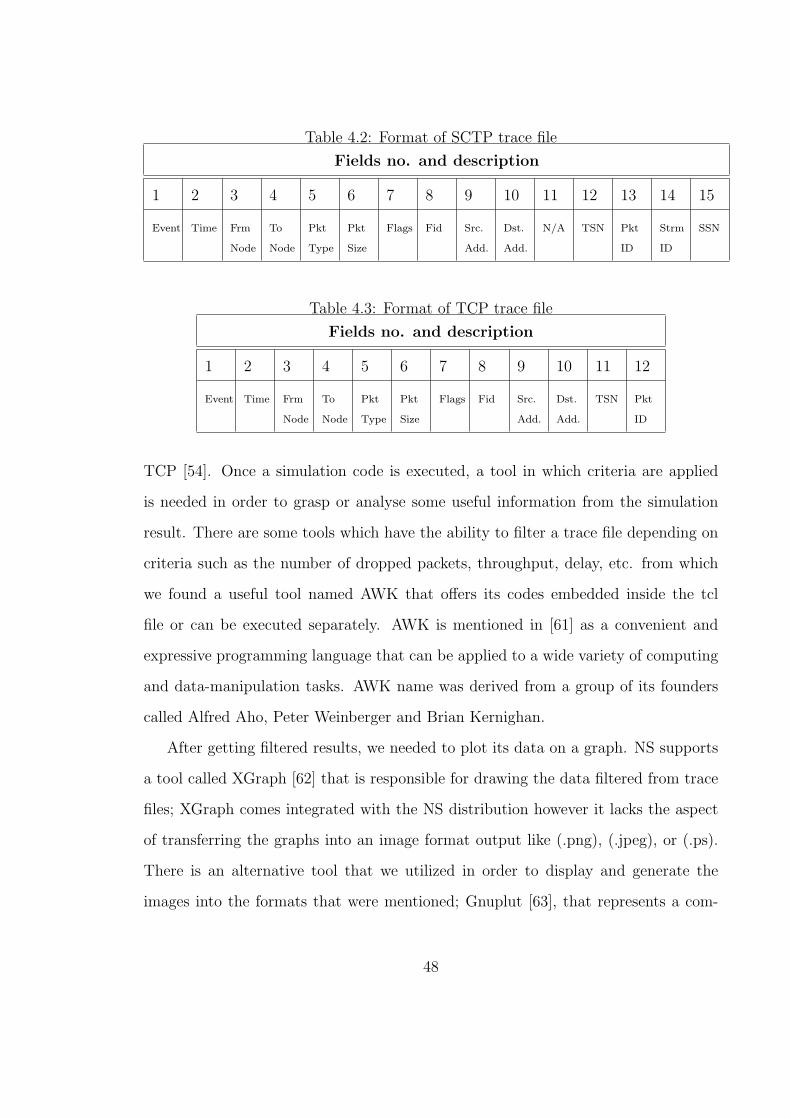
Table 4.2: Format of SCTP trace file
Fields no. and description
1 2 3 4 5 6 7 8 9 10 11 12 13 14 15
Event Time Frm
Node
To
Node
Pkt
Type
Pkt
Size
Flags Fid Src.
Add.
Dst.
Add.
N/A TSN Pkt
ID
Strm
ID
SSN
Table 4.3: Format of TCP trace file
Fields no. and description
1 2 3 4 5 6 7 8 9 10 11 12
Event Time Frm
Node
To
Node
Pkt
Type
Pkt
Size
Flags Fid Src.
Add.
Dst.
Add.
TSN Pkt
ID
TCP [54]. Once a simulation code is executed, a tool in which criteria are applied
is needed in order to grasp or analyse some useful information from the simulation
result. There are some tools which have the ability to filter a trace file depending on
criteria such as the number of dropped packets, throughput, delay, etc. from which
we found a useful tool named AWK that offers its codes embedded inside the tcl
file or can be executed separately. AWK is mentioned in [61] as a convenient and
expressive programming language that can be applied to a wide variety of computing
and data-manipulation tasks. AWK name was derived from a group of its founders
called Alfred Aho, Peter Weinberger and Brian Kernighan.
After getting filtered results, we needed to plot its data on a graph. NS supports
a tool called XGraph [62] that is responsible for drawing the data filtered from trace
files; XGraph comes integrated with the NS distribution however it lacks the aspect
of transferring the graphs into an image format output like (.png), (.jpeg), or (.ps).
There is an alternative tool that we utilized in order to display and generate the
images into the formats that were mentioned; Gnuplut [63], that represents a com-
48

mand line plotting service which is helpful in operating systems that support the CLI
environment like Linux, OSX, MS Windows and other operating systems. Gnuplut
has the ability to plot graphs whether in 2D or 3D effectively. It is strongly advised
to follow the guided steps in order to use NS to get some evaluations of a protocol
or a portion of it, and then to investigate simulation results. There are four recom-
mended steps [64] required in order to produce a graph which demonstrates the data
generated from an NS script:
• A code that is mixed of C++ and OTcl code of that evaluated protocol might
be implemented.
• OTcl scripts that represent the simulated network or topology (like routing
schemes used, nodes, links etc.) should be established.
• Execute the generated codes by running the simulation NS.
• And then, analysing the trace files by using the tools we just mentioned like
NAM that visualizes graphically the simulated codes, XGraph to plot the trace
files or Gnuplut to visualize and printout the investigated files into the formats
we have mentioned previously.
There is no doubt that although we have chosen NS as our principle tool to examine
our research theme, that NS has some drawbacks along with its useful features. As
we have emphasized before, NS particularly nsallinone-2.34 is the most common
simulation software for networks studying in the academic field. The most evidence of
its academic popularity can be seen in some universities such as Delaware, Berkeley of
California (UCB), and Carnegie Melon universities which have contributed to evolving
NS. University of Delaware has participated through their PEL lab in launching ns2.29
distribution, whereas UCB is a very significant volunteer in NS growing nowadays.
49

One of the big troubles of NS is the conflict that might happen between C++ and
OTcl linkage. Users should pay attention once they wish to add new classes into the
hierarchy of NS by choosing the appropriate place as to where that class belongs.
The Table 4.4 describes some of the differences between well known network simu-
lations used for the transport layer protocol such as TCP and its extensions, UDP, or
SCTP (as the simulation we used in our research work); this table interprets some of
the significant points that contribute to why we prefer the distribution of nsallinone-
2.34 over other network simulation softwares, even not considering using the new
distribution called ns3 is based upon its lack of support in terms of transport layer
protocols.
50

Table 4.4: A comparison between ns2 and other simulation softwares [65]
Features OMNeT++ ns2 ns3 SWANS GTNetS
1- TCP
RFC793 + + + + +
TCP Tahoe + + + + +
TCP Reno + + - - +
TCP NewReno - + - - +
TCP Vegas - + - - -
Finite receive buffer - - - + -
TCP header options - + - - -
Timer granularity - + - - +
2- UDP + + + + +
3- SCTP
Basic operation + + - - -
Experimental ext. - + - - -
51
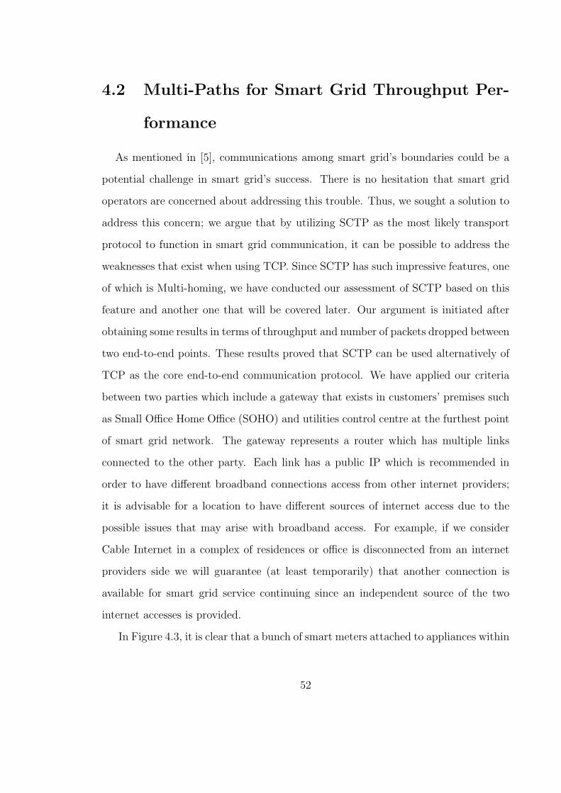
4.2 Multi-Paths for Smart Grid Throughput Per-
formance
As mentioned in [5], communications among smart grid’s boundaries could be a
potential challenge in smart grid’s success. There is no hesitation that smart grid
operators are concerned about addressing this trouble. Thus, we sought a solution to
address this concern; we argue that by utilizing SCTP as the most likely transport
protocol to function in smart grid communication, it can be possible to address the
weaknesses that exist when using TCP. Since SCTP has such impressive features, one
of which is Multi-homing, we have conducted our assessment of SCTP based on this
feature and another one that will be covered later. Our argument is initiated after
obtaining some results in terms of throughput and number of packets dropped between
two end-to-end points. These results proved that SCTP can be used alternatively of
TCP as the core end-to-end communication protocol. We have applied our criteria
between two parties which include a gateway that exists in customers’ premises such
as Small Office Home Office (SOHO) and utilities control centre at the furthest point
of smart grid network. The gateway represents a router which has multiple links
connected to the other party. Each link has a public IP which is recommended in
order to have different broadband connections access from other internet providers;
it is advisable for a location to have different sources of internet access due to the
possible issues that may arise with broadband access. For example, if we consider
Cable Internet in a complex of residences or office is disconnected from an internet
providers side we will guarantee (at least temporarily) that another connection is
available for smart grid service continuing since an independent source of the two
internet accesses is provided.
In Figure 4.3, it is clear that a bunch of smart meters attached to appliances within
52
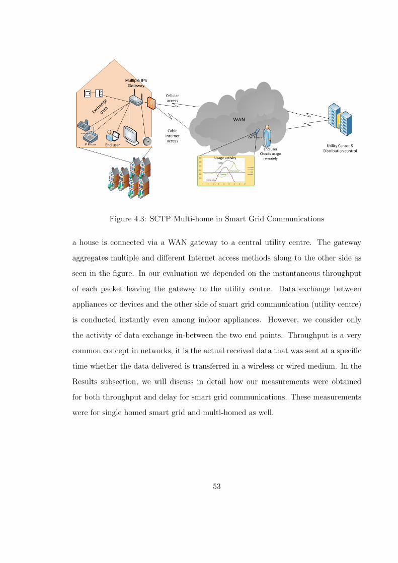
Figure 4.3: SCTP Multi-home in Smart Grid Communications
a house is connected via a WAN gateway to a central utility centre. The gateway
aggregates multiple and different Internet access methods along to the other side as
seen in the figure. In our evaluation we depended on the instantaneous throughput
of each packet leaving the gateway to the utility centre. Data exchange between
appliances or devices and the other side of smart grid communication (utility centre)
is conducted instantly even among indoor appliances. However, we consider only
the activity of data exchange in-between the two end points. Throughput is a very
common concept in networks, it is the actual received data that was sent at a specific
time whether the data delivered is transferred in a wireless or wired medium. In the
Results subsection, we will discuss in detail how our measurements were obtained
for both throughput and delay for smart grid communications. These measurements
were for single homed smart grid and multi-homed as well.
53

4.3 Multi-Streaming Messages for Delay Perfor-
mance Improvement
In addition to the sequential delivery of packets, SCTP has a mechanism of sending
data by splitting it into multiple streams transmitting over the medium and arriving
at the final destination in not sequence of delivery that data was sent by the sender.
This feature is offered as an extra of many SCTP characteristics over TCP’s. Multi-
streaming is a feature in which SCTP derived its unique name and is described in
more detail in Figure 4.4. We conducted some measurements of the Multi-streaming
feature offered by SCTP. On the other hand, we also did some measurements of TCP
which uses a stream of bytes in order to fragment data transmitting along to other
peers. Before discussing our theme, we will briefly go over the predicted results of
using the traditional scheme of TCP applied on smart grid communications.
We already stated that TCP uses a stream of bytes as a reliable delivery mecha-
nism and in the sequence of transmitting side; however this mechanism of transmission
and delivery implies two major problems that weaken TCP’s position in smart grid
communications as a trustful transport protocol. The first problem exists in the fact
that TCP has only a unique strict order of delivery; that means due to a foreseen
delay of packets travelling to the receiving side, this mechanism will enforce the re-
ceivers buffer of the transport protocol to be full of pending packets, and once the
defined sender RTT value goes over, the pending packets get dropped. Furthermore,
within the buffer there are unrelated packets stacked behind the pending ones that
are affected unfairly waiting in line although they are ready to be raised to the upper
layer. This problem of the firmed delivery sequence will have a negative influence
on smart grid communications due to the frequent exchange of data that goes back
and forth in the smart grid communication environment as a behaviour of collecting
54

Figure 4.4: Multi-streaming in Smart Grid Environment
devices status via its meters. The other TCP problem is the nature of the bytes
stream that is sent unbroken into several streams; thus this is vulnerable to mislead-
ing bytes management. Actually the two TCP problems share creating the very well
known TCP problem HoL blocking; the delayed packets waiting for other packets to
be resembled will affect other unrelated ones. Thus, TCP is a byte-based stream pro-
tocol whom we were investigating against SCTP as a message-based, multi-streaming
protocol. Due to the large predicted number of appliances and devices equipped with
meters, smart grid communications will suffer utilizing TCP as its unique transport
protocol. We will cover the delay effects resulted by HoL blocking against the one in
SCTP and why it is wise to utilize SCTP as a prospective transmission (transport)
protocol for smart grid communications in the next subsection.
55

4.4 Results
We have had some unsurprising results due to superiority evidence of SCTP over
TCP. Our results are built on two major measurements which are delay and through-
put for both SCTP and TCP of smart grid communications. Our evaluation outcomes
will be displayed through the next two subsections with a discussion for each one.
4.4.1 Smart Grid Throughput of each SCTP and TCP
We did our measurements simulation of SCTP and TCP as in a wired medium
environment for both multi and single homed situations. We assumed that appliances
or devices have their own medium access type such as Bluetooth, WiFi or Zigbee
that was not counted into our consideration. We did our evaluations of multi-homed
smart grid in normal situations which means no external influences are put in our
considerations.
We calculated data sent from the gateway along to the utility server of smart
grid since we measured only an end-to-end (gateway to server) throughput during
a handover to another link that takes place for both TCP and SCTP. Our multi
homed scenario of smart grid communications simulation assumes that there are
two independent broadband connections which connect a user location to the other
party of the smart grid network. One is a Cable Internet access that represents a
primary link with an upload of 1Mgps whereas the other one is a cellular 3G as a
secondary link with an upload of 2Mgps ; we used the default upload data rate of
Cable Internet access as used nowadays in most Internet providers in Canada, whereas
for the 3G upload we assumed using 2Mb as an average of the uplink speed mentioned
in 3GPP [6]. We scheduled 10 seconds as a simulation time and a switchover from the
56

primary link to the secondary one took place once the simulation time reached the
second 6 for one node simulation and the second 4 for the three nodes simulation for
both of the transport protocols TCP and SCTP respectively. After running the two
simulations for both SCTP and TCP several times we observed that TCP throughput
was degraded severely once the switchover was done in the time specified as graphed
in Figures 4.5 and 4.6 respectively. We actually tried to be fair with TCP by starting
the traffic switching after SSThresh obtained its normal state of the CWND value.
We used the default evenly CWND value for both TCP and SCTP as well. We can
observe in the previous figure that all SCTP and TCP traffic were almost similar
until the handover to the secondary link (cellular connection) started receiving the
traffic which shows a change in TCP behaviour to an unwanted degree although in
our simulation the handover carries the traffic to a wider upload bandwidth. This
note implies the concept that SCTP can manipulate several paths among peered
points with better throughput. SCTP has some significant features as well known,
one of which is called Heartbeat as we have mentioned earlier. This features SCTP in
terms of path management and manipulation which advances an SCTP association
over TCP, not to be affected severely while a handover is in effect to another link.
Thus the number of packets received at the receiver side is maintained to an optimal
threshold.
Since TCP doesn’t have a method of traffic management, a table of routing paths
which is the Network Layer’s role, should be kept and updated in order to keep track
and update other networks. However, this method will have time consuming once
a link is disconnected; thus a rerouting process must be completed within several
seconds which means that the idle time is wasted and this is never preferred in smart
grid communications.
Our experiments were conducted for one and three nodes scenario in order to test
57

0
50
100
150
200
250
0 2 4 6 8 10
Thr
ough
put i
n K
byte
Simulation time in seconds
SCTP vs. TCP one node throughput for smart grid communications
Handover point at 6 for TCP & SCTP
TCP throughputSCTP throughput
Figure 4.5: SCTP vs.TCP one Node Throughput in Multi-homed Connection of
Smart Grid
the effect of smart grid communications with variation in number of devices equipped
with meters. For single node multi-homed smart grid communications, Figure 4.5
depicts the effect of having another route in TCP environment whereas SCTP is not
affected severely, as seen with TCP behaviour , by the handover process because
Heartbeat in SCTP checks periodically the reachability of the other parties’ connec-
tion in addition to the paths establishment when an association is created. SCTP can
be stable once a handover to another path is made, even when the traffic occupies its
primary link as predefined in the starting of an association. When increasing the num-
ber of nodes to 3 as depicted in Figure 4.6, we have noticed a considerable decrease
of throughput due to the pressure applied on communications once a switchover with
more traffic than the previous used for only a singular node. We can observe from the
graph the effect of having many nodes on the throughput of SCTP and TCP that will
58
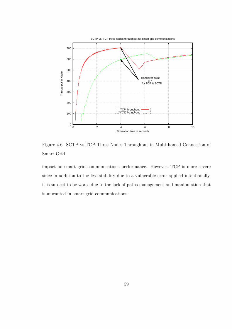
0
100
200
300
400
500
600
700
0 2 4 6 8 10
Thr
ough
put i
n K
byte
Simulation time in seconds
SCTP vs. TCP three nodes throughput for smart grid communications
Handover point at 4 for TCP & SCTP
TCP throughputSCTP throughput
Figure 4.6: SCTP vs.TCP Three Nodes Throughput in Multi-homed Connection of
Smart Grid
impact on smart grid communications performance. However, TCP is more severe
since in addition to the less stability due to a vulnerable error applied intentionally,
it is subject to be worse due to the lack of paths management and manipulation that
is unwanted in smart grid communications.
59
Figure 4.7: SCTP and TCP Packets affected by Handover in Smart Grid Multi-homed
Environment
In number of the packets received or TSN, we observed through Figure 4.7 that
SCTP attempted to keep its packets delivered to the other side of smart grid network
after the switchover is completed whereas TCP is not robust to such switching its
traffic to an alternative path that is seen as a discontinuous of its TSN. This lack of
TCP infers that smart grid will suffer from switching its traffic resulting in dropped
packets and as a consequence, degradation in its performance. TCP’s lack faces a
tied and continuous transmission of SCTP packets even after a handover takes place
as happened in our scenario and demonstrated in the graph. Before we conclude this
subsection, we should mention that not only TCP is not preferred in multi-homing
approach but also TCP is being inappropriate in single homed networks as well.
60

0
200
400
600
800
1000
0 2 4 6 8 10
Thr
ough
put k
b/s
Simulation time in seconds
SCTP & TCP Throughput comparison for Smart Grid of a single home
HoL effect on TCP
TCP throughputSCTP throughput
Figure 4.8: SCTP vs. TCP Throughput for Smart Grid Single Homed Topology
In Figure 4.8, the data we obtained after conducting simulation of a single homed
topology for smart grid proved that weakness of TCP and superiority of SCTP, where
it is clear that a severe degradation in TCP throughput, which was caused by HoLB,
whereas SCTP is stable although its throughput was not started as being increasingly
sharp as one happened in TCP. We observed that TCP was growing well until the HoL
problem occurred in the second 4 that depicts a sharp degradation in the throughput
which is unwanted in smart grid communications. We can perceive from the graph
that SCTP continued growing in throughput due to the concept of multiple streams
method that let packets not be affected by other delayed or dropped packets, whereas
in TCP any packet exceeding its RTT time will make it be retransmitted, resulting
in consecutive ones getting stuck in the buffer of the Transport layer.
61

After conducting our investigations we argue that smart grid communications face
a challenge of keeping meters exchangeable with utility and distribution centres in
an accurate and reliable way that end users look forward, thus from our viewpoint
SCTP with Multi-homing is capable in addressing the lack existing when using TCP
for smart grid transmission in addition to the other SCTP feature that is covered in
the next section.
4.4.2 Delay measured in Smart Grid Communications for
both SCTP and TCP
We measured both SCTP and TCP in an assumed single home smart grid commu-
nication environment. We intentionally conducted a simulation where an error of 10
percent was applied in the middle link. We wanted to investigate each of SCTP and
TCP robustness as another factor that might affect smart grid communications. The
error model comes with ns2.34 to simulate performance degradation on a protocol.
We scheduled the error for both SCTP and TCP in the middle of the first second.
Since our intention was to evaluate the performance of TCP which supports streams
as byte based and SCTP as multiple stream based, we didn’t consider the multiple
paths between the peered end points. We intended on evaluating a criterion that has
a major effect on smart grid communication performance, which is the delay, partic-
ularly end-end delay which exists in between the HAN gateway and the furthest end
at the utility/distribution centre. We have investigated two kinds of delay, instanta-
neous and accumulative respectively . The instantaneous one is defined as the time
difference resulting from the senders side and receivers side times of a packet. The
delay calculation is assumed via measuring the instantaneous delay of every packet
leaving the sender and targeting the receiver. As well, we did the overall delay calcu-
62

lation as a cumulative delay of all instantaneous ones up to the simulation end. The
two delays measured are mentioned in 1 and 2 AWK outcomes respectively.
D_p = 0 (packet delay);
R_t = 0 (receiving time);
S_t = 0 (sending time);
TSN_S(Sender TSN);
D_p = R_d(TSN_S) - S_d(TSN_S)
.
.
Current delay = D_p ---> 1
Overall delay (all packets) = Overall delay + Current_delay ---> 2
As a packet traversing in a medium, a normal latency is reserved for each medium
type. Thus we calculated the delay for both SCTP that applies Multi-stream and
TCP as a byte based stream. First, we built an assumed topology for both SCTP
and TCP as there is a gateway of HAN network that holds some appliances and
devices equipped with meters behind it. This gateway connects to the furthest point
that is the utility control and distribution centres via a WAN network. The SCTP
Multi-streaming feature was enabled whereas in TCP we have only one option to
measure the delay which is via utilizing the single byte stream method. Continually,
Transmission Sequence Number (TSN) was the value that we used in order to identify
the delay of each packet transmitted. We used AWK code to analyse and filter the
data through trace files generated by the NS2 of our topology and we also had some
results which were built on some of the factors that we applied. An excerpt of the
AWK is shown in the following script lines:
Current_delay =0;
63
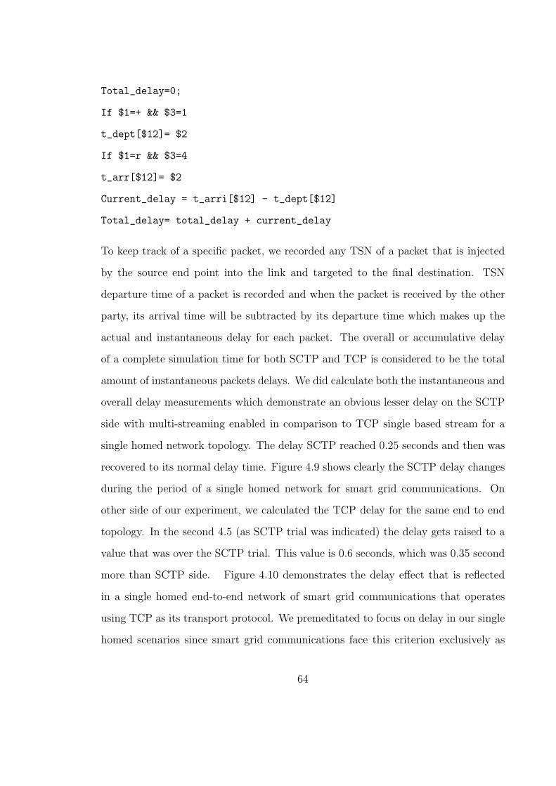
Total_delay=0;
If $1=+ && $3=1
t_dept[$12]= $2
If $1=r && $3=4
t_arr[$12]= $2
Current_delay = t_arri[$12] - t_dept[$12]
Total_delay= total_delay + current_delay
To keep track of a specific packet, we recorded any TSN of a packet that is injected
by the source end point into the link and targeted to the final destination. TSN
departure time of a packet is recorded and when the packet is received by the other
party, its arrival time will be subtracted by its departure time which makes up the
actual and instantaneous delay for each packet. The overall or accumulative delay
of a complete simulation time for both SCTP and TCP is considered to be the total
amount of instantaneous packets delays. We did calculate both the instantaneous and
overall delay measurements which demonstrate an obvious lesser delay on the SCTP
side with multi-streaming enabled in comparison to TCP single based stream for a
single homed network topology. The delay SCTP reached 0.25 seconds and then was
recovered to its normal delay time. Figure 4.9 shows clearly the SCTP delay changes
during the period of a single homed network for smart grid communications. On
other side of our experiment, we calculated the TCP delay for the same end to end
topology. In the second 4.5 (as SCTP trial was indicated) the delay gets raised to a
value that was over the SCTP trial. This value is 0.6 seconds, which was 0.35 second
more than SCTP side. Figure 4.10 demonstrates the delay effect that is reflected
in a single homed end-to-end network of smart grid communications that operates
using TCP as its transport protocol. We premeditated to focus on delay in our single
homed scenarios since smart grid communications face this criterion exclusively as
64

0.19
0.2
0.21
0.22
0.23
0.24
0.25
0.26
0 2 4 6 8 10
E2E
del
ay in
sec
onds
Simulation time in seconds
Delay effect on SCTP TSN for Smart Grid
Delay of received SCTP TSN
Figure 4.9: SCTP delay of a Single Homed Topology for Smart Grid
0.1
0.2
0.3
0.4
0.5
0.6
0.7
0 2 4 6 8 10
E2E
del
ay in
sec
onds
Simulation time in seconds
Delay effect on TCP TSN for Smart Grid
Delay of received TCP TSN
Figure 4.10: TCP delay of a Single Homed Topology for Smart Grid
65

0.1
0.2
0.3
0.4
0.5
0.6
0.7
0 2 4 6 8 10
Del
ay in
sec
onds
Simulation time in seconds
SCTP & TCP Delay comparison for Smart Grid of a single home link
TCP delaySCTP delay
Figure 4.11: SCTP and TCP Delays combined together of a Smart Grid Network
an obstacle in its path to full deployment. Accordingly, we can distinguish the delay
difference between SCTP and TCP in terms of performance optimization.
We can notice this in Figure 4.11 that gathers SCTP and TCP delays, which
undoubtedly make SCTP unique in functioning as the feasible transport protocol for
smart grid communications. That means SCTP delay should occur less in the Multi-
homing event so the overall performance is feasible in order to optimize higher levels
in smart grid communication, that applies SCTP as its transport protocol in an end-
to-end environment. In terms of the actual data received (which is the throughput)
by the other side of a single smart grid network.
66

4.5 Summary
In this chapter, we introduced our key work where we proposed using Multi-homing
and Multi-streaming which implies utilizing SCTP as the key transport protocol for
smart grid communications. We demonstrated that there were many simulation soft-
wares to choose from in order to investigate our assumptions. Network Simulator
version 2.34 (ns2) has been used to test both SCTP and TCP in which smart grid
might rely. Ns2 is non-profit software that is targeted to both academic and research
oriented fields and supported by some educational firms. There were many causes that
drove us to utilize this, but the most significant one is the full support of SCTP and
its extensions, as well as its popularity among research fields. Since smart grid is still
in its infancy, we found some research claims that many challenges face its progress.
One of which is exist in its communication as an obstacle which requires further ex-
aminations in order to accelerate smart grid deployment. We noticed that since TCP
has some limitations like Head of Line Blocking (HoLB) which can lead to potential
failure, it is not suitable to be used as the transport protocol for smart grid com-
munication. We did many experiments for both Multi-homing and Multi-streaming
using our tools; based on our results, we propose that smart grid can optimize its
communication performance since SCTP can be utilized to play the transport proto-
col between end to end nodes. We found two crucial criteria that differentiates SCTP
as being better than TCP for smart grid communications; throughput and delay
respectively. Once handover was intentionally made, TCP throughput was affected
negatively showing that the transport layer buffer was filled by in-line packets which
create (HoLB) problem as one of TCP drawbacks. On the other hand, we found
that SCTP throughput was robust to changing the path to another predefined path
in the transport layer which is not offered by TCP. In terms of delay, this criterion
was observed clearly, and TCP delay was increasing over SCTP’s due to the concept
67

that TCP is incapable of transmitting multi-streams like SCTP. Our outcomes show
that SCTP has less delay periods in comparison to TCP in a single homed topology;
SCTP delay was 0.35 seconds lesser than TCP’s ones.
68
Chapter 5
Conclusions and Future Work
5.1 Conclusions
We propose in this thesis a mechanism of enhancing smart grid communications
performance by utilizing Streaming Control Transmission Protocol (SCTP) instead
of TCP as the main transport protocol between the end-to-end points of smart grid
communication network. We suggest specifically two major features of SCTP Multi-
homing and Multi-streaming respectively. Since smart grid providers are concerned
about increasing the reliability of smart grid service among their consumers, it is wise
to provide the availability needed of smart grid communication between its two sides
by using Multi-homing feature as one side of our theme. This can be achieved by
offering multiple paths between the gateway, which represents the edge of a user end
point before WAN connection, and the utility end point and distribution centre in
which smart grid control exists. These paths should be predefined in the Transport
layer instead of building a bunch of routing tables in the Network layer. Once there
are multiple paths utilized between the two smart grid parties, mechanism of service
availability are offered; these are very crucial in the instance of a link disconnection
or traffic overload which may occur. On the other side, using Multi-streaming within
69

smart grid network, its feasible to enhance throughput since this will mitigate the
probability of messages being affected by HoLB problem that is known in TCP. Once
smart grid increases its communications performance, this will likely lead to have
much more reliability then by using the mainstream mechanism used by TCP which
uses a message based stream, only providing a strict order of packet deliveries. Our
experiments whom we conducted on both TCP and SCTP have proved that the
delay is less when using SCTP in smart grid environment; we found that SCTP
delay is 0.35 second lesser than TCP, the delay was calculated between the edges of
the users gateway and the furthest point of smart grid which is the utility centre.
Also, using Multi-homing of SCTP, the throughput doesn’t get affected much by the
switching over of connections to an alternative path, whereas in TCP the throughput
is decreased dramatically due to changing the traffic to other paths.
We believe that since electrical companies are concerned about conserving elec-
tricity consumption, it is worthy to benefit from utilizing SCTP. Not only looking for
smart grid performance enhancing but also mitigating CO2 emissions by one of smart
grid objectives which is concentrated on controlling the electricity consumption by
end users in addition to its providers.
70
5.2 Future Work
Since SCTP shares many of the effective TCP features, this can be a supportive
way to a smooth integration of SCTP with ongoing communications entities. Espe-
cially when we notice that governments are extremely serious in converging to green
alternatives in order to resolve the safe alternatives in which our Earth gets rid of
threats resulting from the technology revolution. A lot of research is undergoing in
order to provide climate-friendly solutions for many troubles facing our future; one
of which is figuring out an effective way to decline power consumption. We think
that having a mechanism like smart grid, which regulates electricity consumption
and control, can play the prime effect of degradation in this tackle. As mentioned
previously, smart grid implies an idea of granting consumers of electricity the ability
to react to their consumption whether immediate or predefined actions. This ability
not only provides monthly or weekly real time data as previous but also activities of
meters every some minutes which involves a potential trend that many smart meters
vendors should consider.
In addition to the trend of data management, some crucial trends facing smart grid
in the near future can draw to its success as mentioned in [66], the highest priority of
these trends is the security since SCADA possesses the key task in which smart grid is
integrated and interconnected [68]. This infers a concern about any potential threat
that smart grid is subject to. This concern urges vendors of smart meters to work on
this trend carefully before announcing their smart grid launching. Also another trend
focuses on HAN in SOHO. This trend carries some aware issues that might postpone
smart grid, for example, although smart grid involves mesh networking between its
meters, HAN meters are still under development [66]. There is no doubt that many
applications nowadays can benefit from using SCTP which has a fertile basic for
researchers in the foreseen future. One of which is load sharing that can be exploited
71

by Concurrent Multiple Transfer as draft mentioned in [67]. Indeed CMT is a key
feature offered by SCTP that is open to be worked on later, as we plan to potentially
have some works conducted on it.
Since my country (Saudi Arabia) is one of the countries who has many hours of
sunlight throughout the whole year which is considered un-utilized energy source,
this field is deserving a research concentration in order to mitigate the suppression of
depleted power resources. Actually, this matter grasped our attention in conducting
future research. We believe that SCTP can play a major role in smart grid’s roadmap
since the world is switching to safer and cleaner alternatives in order to meet their
needs in a way that can assure harmless suppression on Earth. We emphasise that
electricity providers should take advantage of using smart grid by regulating electricity
consumption hours among their customers and providing them with accurate charts
and reports about daily, weekly or monthly electricity usage, which will be reflected
appropriately on a variety of their life matters.
72

Appendix A
Simulation Scripts
Here is the place where the scripts of our smart grid simulation are conducted for
both SCTP and TCP. The scripts are organized into section in respect to the results
graphed in Chapter 4.
A.1 Smart grid throughput multi-homing one node
A.1.1 SCTP
#This script demonstrates multihoming. Two smart grid endpoints enabled
#with SCTP, each with 2 interfaces, are directly connected through a pair
#of interfaces. In a scheduled time of the association, a change of primary
#link is made. Running nam helps to visualize the multi-homed architecture.
(2) Primary(Cable) (5)
# host0_if0 O===========================O host1_if0
# / \
# (0)n0 ========= O (1)host0_core host1_core O (4)
# \ /
# host0_if1 O===========================O host1_if1
# (3) Secondary(3G) (6)
73
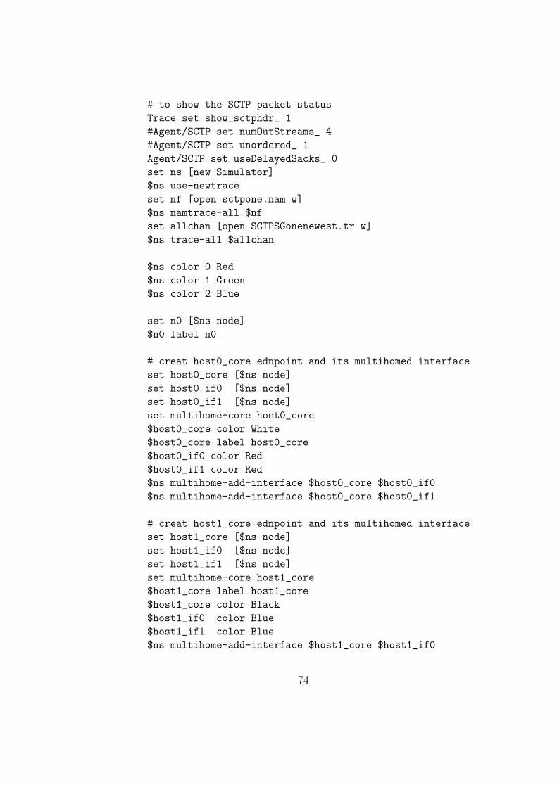
# to show the SCTP packet status
Trace set show_sctphdr_ 1
#Agent/SCTP set numOutStreams_ 4
#Agent/SCTP set unordered_ 1
Agent/SCTP set useDelayedSacks_ 0
set ns [new Simulator]
$ns use-newtrace
set nf [open sctpone.nam w]
$ns namtrace-all $nf
set allchan [open SCTPSGonenewest.tr w]
$ns trace-all $allchan
$ns color 0 Red
$ns color 1 Green
$ns color 2 Blue
set n0 [$ns node]
$n0 label n0
# creat host0_core ednpoint and its multihomed interface
set host0_core [$ns node]
set host0_if0 [$ns node]
set host0_if1 [$ns node]
set multihome-core host0_core
$host0_core color White
$host0_core label host0_core
$host0_if0 color Red
$host0_if1 color Red
$ns multihome-add-interface $host0_core $host0_if0
$ns multihome-add-interface $host0_core $host0_if1
# creat host1_core ednpoint and its multihomed interface
set host1_core [$ns node]
set host1_if0 [$ns node]
set host1_if1 [$ns node]
set multihome-core host1_core
$host1_core label host1_core
$host1_core color Black
$host1_if0 color Blue
$host1_if1 color Blue
$ns multihome-add-interface $host1_core $host1_if0
74
$ns multihome-add-interface $host1_core $host1_if1
# create a link between n0 & host0_core
$ns duplex-link $n0 $host0_core 250Kb 10ms DropTail
# Primary link (DSL uplink speed)
$ns duplex-link $host0_if0 $host1_if0 1Mb 5ms DropTail
# Secondary link (3G uplink speed)
$ns duplex-link $host0_if1 $host1_if1 2Mb 5ms DropTail
$ns duplex-link-op $host0_if0 $host1_if0 label Primary
$ns duplex-link-op $host0_if0 $host1_if0 color white
$ns duplex-link-op $host0_if1 $host1_if1 label Secondary
$ns duplex-link-op $host0_if1 $host1_if1 color white
#Setup an SCTP connection for n0
set sctp0 [new Agent/SCTP]
$sctp0 set fid_ 1
$sctp0 set dataChunkSize_ 1008
$ns attach-agent $n0 $sctp0
set ftp0 [new Application/FTP]
$ftp0 attach-agent $sctp0
#$ftp0 set class_ 2
#$ftp0 set fid_ 1
set sctp1 [new Agent/SCTP]
$ns multihome-attach-agent $host0_core $sctp1
$sctp1 set dataChunkSize_ 1008
$sctp1 set fid_ 2
#Setup an SCTP connection for host0_core
set sctp2 [new Agent/SCTP]
$sctp2 set dataChunkSize_ 1008
$ns multihome-attach-agent $host1_core $sctp2
#$sctp0 set class_ 1
$ns connect $sctp0 $sctp2
$ns connect $sctp1 $sctp2
# set a primary destination before association starts;
75

$sctp0 set-primary-destination $host1_if0
#Primary routes (default)
$host0_core add-route 4 2
$host0_if0 add-route 4 5
$host1_if0 add-route _o44 4
$host1_if0 add-route 0 _o18
$host0_if0 add-route 0 _o15
$host1_core add-route _o44 0
# change primary;
$ns at 4 "$sctp0 set-primary-destination $host1_if1"
$ns at 4 "$ns trace-annotate \"Switchover to the secondary
link done at 4\""
# Secondary routes
$host0_core add-route 4 3
$host0_if1 add-route 4 6
$host1_if1 add-route _o44 4
$host1_if1 add-route 0 _o21
$host0_if1 add-route 0 _o15
# ftp0 between n0 & host0_core
$ns at 0.1 "$ftp0 start"
set old_data1 0
set old_data2 0
proc finish {} {
global ns nf allchan
$ns flush-trace
#Close the trace files
close $nf
## AWK code to extract the data that will be depicted in Gnuplot
exec awk {
{
if (($1=="r" && $4=="5" && $6=="1040") ||
($1=="r" && $4=="6" && $6=="1040")) {
old_data1=old_data1 + $6
print $2,tab,tab,$12
76

}
}
} SCTPSGonenewest.tr > SCTPTSN.data
exec awk {
{
if (($1=="r" && $4=="5" && $6=="1040") ||
($1=="r" && $4=="6" && $6=="1040")) {
old_data2=old_data2 + $6
print $2,old_data2*8/$2/1000
}
}
} SCTPSGonenewest.tr > SCTPthroughputN.data
exec awk {
{
if ($1=="d" && ($6=="1040" || $6=="40") ) {
#drop_data=old_data + $6
print $2,tab,$12
}
}
} SCTPSGonenewest.tr > SCTPdrop.data
## This code to run NAM that will graph the data once ns
## is executed
exec xgraph -t SCTPThroughput -nl -M -x time(s)
-y SCTPthroughput(Kb/s) SCTPthroughputN.data
-geometry 800x500 &
exit 0
}
$ns at 10 "finish"
puts "Starting Simulation..."
puts "n0 id = [$n0 id]"
puts "host0_core = [$host0_core id]"
puts "host1_core = [$host1_core id]"
puts "host0_if0 = [$host0_if0 id]"
puts "host1_if0 = [$host1_if0 id ]"
puts "host0_if1 = [$host0_if1 id]"
puts "host1_if1 = [$host1_if1 id]"
77
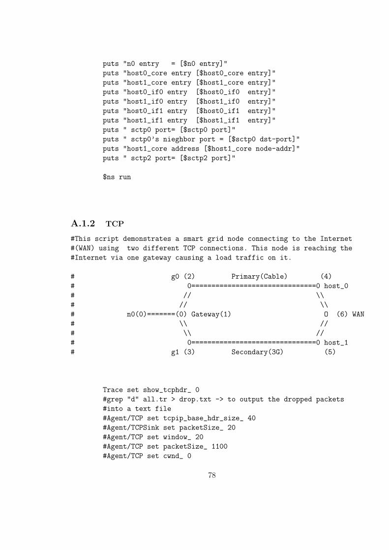
puts "n0 entry = [$n0 entry]"
puts "host0_core entry [$host0_core entry]"
puts "host1_core entry [$host1_core entry]"
puts "host0_if0 entry [$host0_if0 entry]"
puts "host1_if0 entry [$host1_if0 entry]"
puts "host0_if1 entry [$host0_if1 entry]"
puts "host1_if1 entry [$host1_if1 entry]"
puts " sctp0 port= [$sctp0 port]"
puts " sctp0’s nieghbor port = [$sctp0 dst-port]"
puts "host1_core address [$host1_core node-addr]"
puts " sctp2 port= [$sctp2 port]"
$ns run
A.1.2 TCP
#This script demonstrates a smart grid node connecting to the Internet
#(WAN) using two different TCP connections. This node is reaching the
#Internet via one gateway causing a load traffic on it.
# g0 (2) Primary(Cable) (4)
# 0===============================0 host_0
# // \\
# // \\
# n0(0)=======(0) Gateway(1) O (6) WAN
# \\ //
# \\ //
# 0===============================0 host_1
# g1 (3) Secondary(3G) (5)
Trace set show_tcphdr_ 0
#grep "d" all.tr > drop.txt -> to output the dropped packets
#into a text file
#Agent/TCP set tcpip_base_hdr_size_ 40
#Agent/TCPSink set packetSize_ 20
#Agent/TCP set window_ 20
#Agent/TCP set packetSize_ 1100
#Agent/TCP set cwnd_ 0
78
set ns_ [new Simulator]
$ns_ rtproto DV
$ns_ color 0 Red
$ns_ color 1 Green
$ns_ color 2 Blue
$ns_ color 3 Gray
set nf [open tcpsg.nam w]
$ns_ namtrace-all $nf
set allchan [open TCPsingle.tr w]
$ns_ trace-all $allchan
# Creating all nodes
set n0 [$ns_ node]
$n0 label n0
$n0 color Red
set gateway [$ns_ node]
$gateway label Gateway
$gateway color Gray
set g0 [$ns_ node]
$g0 label g0
$g0 color Purple
set g1 [$ns_ node]
$g1 label g1
$g1 color Purple
set host_0 [$ns_ node]
$host_0 label host_0
set host_1 [$ns_ node]
$host_1 label host_1
set wan [$ns_ node]
$wan label WAN
$wan color Black
# Creating the links and topolgy
$ns_ duplex-link $n0 $gateway 250Kb 10ms DropTail
79
$ns_ duplex-link $gateway $g0 250kb 15ms DropTail
# Primary link (DSL)
$ns_ duplex-link $g0 $host_0 1Mb 10ms DropTail
$ns_ duplex-link $host_0 $wan 1Mb 10ms DropTail
$ns_ duplex-link $gateway $g1 250kb 15ms DropTail
# Secondary link (3G )
$ns_ duplex-link $g1 $host_1 1Mb 10ms DropTail
$ns_ duplex-link $host_1 $wan 1Mb 10ms DropTail
# the limit of gateway & wan queue
#$ns_ queue-limit $g0 $host_0 10
#$ns_ queue-limit $g1 $host_1 10
$ns_ queue-limit $gateway $g0 10
$ns_ queue-limit $gateway $g1 10
# nodes locations_ in NAM
$ns_ duplex-link-op $n0 $gateway orient right
$ns_ duplex-link-op $gateway $g0 orient right-up
$ns_ duplex-link-op $g0 $host_0 orient right
$ns_ duplex-link-op $host_0 $wan orient right-down
$ns_ duplex-link-op $gateway $g1 orient right-down
$ns_ duplex-link-op $g1 $host_1 orient right
$ns_ duplex-link-op $host_1 $wan orient right-up
$ns_ duplex-link-op $g0 $host_0 label Primary
$ns_ duplex-link-op $g1 $host_1 label Secondary
#Monitor the queue for the link between node 2 and node 3
#$ns_ duplex-link-op $gateway $wan queuePos 0.5
#Setup a TCP connection for n0
set tcp0 [new Agent/TCP]
$tcp0 set packetSize_ 1000
#$tcp0 trace cwnd_ 0
$ns_ attach-agent $n0 $tcp0
$tcp0 set fid_ 0
set ftp0 [new Application/FTP]
$ftp0 attach-agent $tcp0
$ftp0 set packetSize_ 1000
$ftp0 set interval_ 0.005
80
#$ftp0 set type_ CBR
$ftp0 set class_ 0
# Creating the sinks agents at wan
set dstn0 [new Agent/TCPSink]
$ns_ attach-agent $wan $dstn0
set dstn1 [new Agent/TCPSink]
$ns_ attach-agent $wan $dstn1
$ns_ rtmodel-at 4 down $g0 $host_0
$ns_ rtmodel-at 4 down $g1 $host_1
$ns_ rtmodel-at 5.3 up $g1 $host_1
puts "WAN = [$wan id]"
puts "host_1 = [$host_1 id]"
puts "host_0 = [$host_0 id]"
puts "g0 = [$g0 id]"
puts "g1 = [$g1 id]"
# A trace file for the two nodes(gateway $wan) link
# set qfl [open qf.tr w]
#$ns_ trace-queue $gateway $wan $qfl
# To monitor a specific link, Specify which (existing)
#link to monitor
set slink0 [$ns_ link $gateway $g0]
# Create monitor
set fmon0 [$ns_ makeflowmon Fid]
$ns_ attach-fmon $slink0 $fmon0
set slink1 [$ns_ link $gateway $g1]
# Create monitor
set fmon1 [$ns_ makeflowmon Fid]
$ns_ attach-fmon $slink1 $fmon1
set trace_ch [open trace.tcp0 w]
$tcp0 set trace_all_ 0
$tcp0 trace cwnd_
$tcp0 trace rtt_
$tcp0 trace rto_
$tcp0 attach $trace_ch
81

set old_data 0
#set trace_file [open trace_file.out w]
#Define the finish procedure that closes the trace files and starts
#nam and xgraph
proc finish {} {
global ns_ nf allchan fmon0 fmon1
$ns_ flush-trace
#Close the trace file(s)
close $nf
puts "## no. of link0 packet dropped =[$fmon0 set pdrops_] "
puts "## no. of link1 packet dropped =[$fmon1 set pdrops_] "
# Get data from trace file, put current-time and calculated-
# throughput in a new file
exec awk {
{
if (($1=="r" && $4=="6" && $6=="1040" )) {
old_data=old_data + $6
print $2,tab,tab,old_data*8/$2/1000
}
}
} TCPsingle.tr > TCPthroughputN.data
exec awk {
{
if ($1 =="r" && $4=="6" && $6=="1040" && $8=="0") {
#old_data=old_data + $6
print $2,tab,tab,$11
}
}
} TCPsingle.tr > TCPTSNtraffic0.data
exec awk {
{
if ($1 =="r" && $4=="6" && $6=="1040" && $8=="1") {
#old_data=old_data + $6
print $2,tab,tab,$11
}
}
} TCPsingle.tr > TCPTSNtraffic1.data
82

exec awk {
{
if (($1=="d" && $5=="tcp" || $1=="d" && $5=="ack")) {
#drop_data=old_data + $6
print $2,tab,$11,tab,tab,$8
}
}
} TCPsingle.tr > TCPdrop.data
# Call xgraph plotting program to plot throughput vs time
exec xgraph -t TSN(vs.)Drop -nl -M -x time -y TSN&drop
TCPTSNtraffic0.data TCPTSNtraffic1.data TCPdrop.data
-geometry 800x500 &
exec xgraph -t Throughput -nl -M -x time -y Throughput
TCPthroughputN.data -geometry 800x500 &
exit 0
}
# ftp0 between n0 & gateway
$ns_ at 0.1 "$ftp0 start"
#print all dests’ cwnds at time 2.4;
#$ns_ at 2.4 "$tcp0 print cwnd_"
$ns_ at 10 "finish"
puts "Starting Simulation..."
$ns_ run
A.2 Smart grid throughput multi-homing three nodes
A.2.1 SCTP
## Edited by Majed in Thu 08 Mar 2012 09:35:37 PM EST ##
# create the event schedueler
# turn on tracing
# create the network by:
83
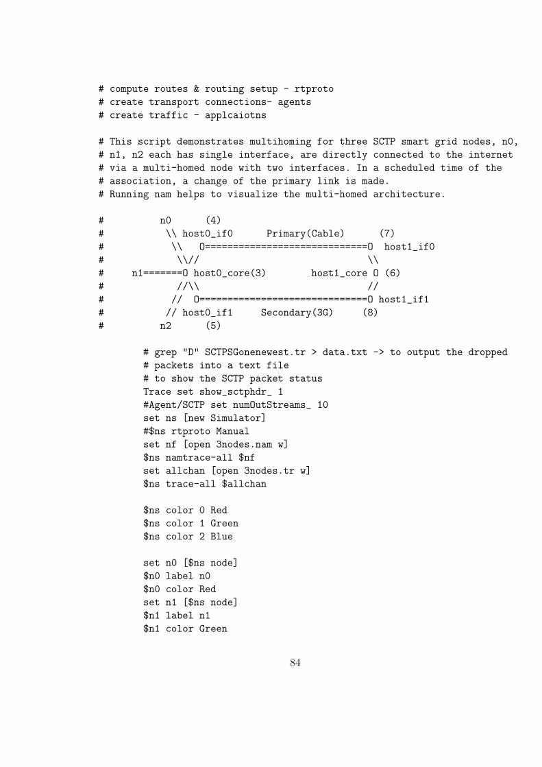
# compute routes & routing setup - rtproto
# create transport connections- agents
# create traffic - applcaiotns
# This script demonstrates multihoming for three SCTP smart grid nodes, n0,
# n1, n2 each has single interface, are directly connected to the internet
# via a multi-homed node with two interfaces. In a scheduled time of the
# association, a change of the primary link is made.
# Running nam helps to visualize the multi-homed architecture.
# n0 (4)
# \\ host0_if0 Primary(Cable) (7)
# \\ O=============================O host1_if0
# \\// \\
# n1=======O host0_core(3) host1_core O (6)
# //\\ //
# // O==============================O host1_if1
# // host0_if1 Secondary(3G) (8)
# n2 (5)
# grep "D" SCTPSGonenewest.tr > data.txt -> to output the dropped
# packets into a text file
# to show the SCTP packet status
Trace set show_sctphdr_ 1
#Agent/SCTP set numOutStreams_ 10
set ns [new Simulator]
#$ns rtproto Manual
set nf [open 3nodes.nam w]
$ns namtrace-all $nf
set allchan [open 3nodes.tr w]
$ns trace-all $allchan
$ns color 0 Red
$ns color 1 Green
$ns color 2 Blue
set n0 [$ns node]
$n0 label n0
$n0 color Red
set n1 [$ns node]
$n1 label n1
$n1 color Green
84

set n2 [$ns node]
$n2 label n2
$n2 color Blue
# creat host0_core ednpoint and its multihomed interface
set host0_core [$ns node]
set host0_if0 [$ns node]
set host0_if1 [$ns node]
set multihome-core host0_core
$host0_core color White
$host0_core label host0_core
$host0_if0 color Red
$host0_if1 color Red
$ns multihome-add-interface $host0_core $host0_if1
$ns multihome-add-interface $host0_core $host0_if0
# creat host1_core ednpoint and its multihomed interface
set host1_core [$ns node]
set host1_if0 [$ns node]
set host1_if1 [$ns node]
set multihome-core host1_core
$host1_core label host1_core
$host1_core color Black
$host1_if0 color Blue
$host1_if1 color Blue
$ns multihome-add-interface $host1_core $host1_if1
$ns multihome-add-interface $host1_core $host1_if0
# create a link between n0 & host0_core
$ns duplex-link $n0 $host0_core 250Kb 10ms DropTail
# create a link between n1 & host0_core
$ns duplex-link $n1 $host0_core 250Kb 10ms DropTail
# create a link between n2 & host0_core
$ns duplex-link $n2 $host0_core 250Kb 10ms DropTail
# Primary link (DSL uplink speed)
$ns duplex-link $host0_if0 $host1_if0 1Mb 5ms DropTail
# Secondary link (3G uplink speed)
$ns duplex-link $host0_if1 $host1_if1 2Mb 5ms DropTail
85

# Layout in NAMAgent/SCTP set numOutStreams_ 4
$ns duplex-link-op $n0 $host0_core orient right-down
$ns duplex-link-op $n1 $host0_core orient right
$ns duplex-link-op $n2 $host0_core orient right-up
$ns duplex-link-op $host0_if0 $host1_if0 label Primary
$ns duplex-link-op $host0_if0 $host1_if0 color gray
$ns duplex-link-op $host0_if1 $host1_if1 label Secondary
$ns duplex-link-op $host0_if1 $host1_if1 color gray
#Setup an SCTP connection for n0
set sctp0 [new Agent/SCTP]
$sctp0 set dataChunkSize_ 1008
$sctp0 set fid_ 0
$ns attach-agent $n0 $sctp0
#$sctp0 set packetsize_ 500
set ftp0 [new Application/FTP]
$ftp0 attach-agent $sctp0
$ftp0 set class_ 0
#$ftp0 set packetSize_ 500
#$ftp0 set interval_ 0.005
#Setup an SCTP connection for n1
set sctp1 [new Agent/SCTP]
$sctp1 set dataChunkSize_ 1008
$sctp1 set fid_ 1
$ns attach-agent $n1 $sctp1
#$sctp1 set packetsize_ 500
set ftp1 [new Application/FTP]
$ftp1 attach-agent $sctp1
$ftp1 set class_ 1
#$ftp1 set packetSize_ 500
#$ftp1 set interval_ 0.005
#Setup an SCTP connection for n2
set sctp2 [new Agent/SCTP]
$sctp2 set dataChunkSize_ 1008
$sctp2 set fid_ 2
$ns attach-agent $n2 $sctp2
86

#$sctp2 set packetsize_ 500
set ftp2 [new Application/FTP]
$ftp2 attach-agent $sctp2
$ftp2 set class_ 2
#$ftp2 set packetSize_ 500
#$ftp2 set interval_ 0.005
#Setup an SCTP connection for host0_core
set sctp0core [new Agent/SCTP]
$ns multihome-attach-agent $host0_core $sctp0core
#Setup an SCTP connection for host1_core
set sctp1core [new Agent/SCTP]
$ns multihome-attach-agent $host1_core $sctp1core
#Setup an SCTP connection for host0_core -->n0
set sctp1core0 [new Agent/SCTP]
$ns multihome-attach-agent $host1_core $sctp1core0
#Setup an SCTP connection for host0_core -->n1
set sctp1core1 [new Agent/SCTP]
$ns multihome-attach-agent $host1_core $sctp1core1
#Setup an SCTP connection for host0_core -->n2
set sctp1core2 [new Agent/SCTP]
$ns multihome-attach-agent $host1_core $sctp1core2
$ns connect $sctp0 $sctp1core0
$ns connect $sctp1 $sctp1core1
$ns connect $sctp2 $sctp1core2
$ns connect $sctp0core $sctp1core
# set a primary destination before association starts for all
# three nodes;
$sctp0 set-primary-destination $host1_if0
$sctp1 set-primary-destination $host1_if0
$sctp2 set-primary-destination $host1_if0
# Primary routes (default)
$host0_core add-route 6 _o24
87
$host0_if0 add-route 6 _o53
$host1_if0 add-route 6 _o50
$host1_core add-route 6 0
$host1_core add-route 0 _o53
$host1_core add-route 1 _o53
$host1_core add-route 2 _o53
$host1_if0 add-route 0 3
$host1_if0 add-route 1 3
$host1_if0 add-route 2 3
$host0_if0 add-route 0 _o21
$host0_if0 add-route 1 _o21
$host0_if0 add-route 2 _o21
# change primary;
$ns at 4 "$sctp0 set-primary-destination $host1_if1"
$ns at 4 "$sctp1 set-primary-destination $host1_if1"
$ns at 4 "$sctp2 set-primary-destination $host1_if1"
$ns at 4 "$ns trace-annotate \"Switchover to Secondary link
done at 4\""
# print all dests’ cwnds at time 7.5;
#$ns at 7.5 "$sctp0 print cwnd_"
# Secondary routes
$host0_core add-route 6 _o27
$host0_if1 add-route 6 8
$host1_if1 add-route _o50 6
#$host0_core delete-route 4 2
#$host0_if0 delete-route 4 _o47
#$host1_if0 delete-route 4 _o44
#$host1_core delete-route 4.0 0
# ftp0 between n0 & host0_core
$ns at 0.1 "$ftp0 start"
#$ns at 8.1 "$ftp0 stop"
# ftp1 between n1 & host0_core
$ns at 0.1 "$ftp1 start"
#$ns at 8.1 "$ftp1 stop"
88
# ftp2 between n2 & host0_core
$ns at 0.1 "$ftp2 start"
#$ns at 8.1 "$ftp2 stop"
# Now we have to open three output files. The following lines
# have to appear ’early’ in the Tcl script.
set old_data 0
set pri_data 0
#set sec_data 0
proc finish {} {
global ns nf allchan old_data
$ns flush-trace
close $nf
close $allchan
# Graph the entire association on one graph
exec awk {
{
if (($1=="r" && $4=="7" && $6=="1040") || ($1=="r" &&
$4=="8" && $6=="1040")) {
old_data=old_data + $6
print $2, old_data*8/$2/1000
}
}
} 3nodes.tr > SCTPthroughput.data
# Ploting the Primary link throughput host0_core --->
# host0_if0---> host1_if0
exec awk {
{
if (($1=="r" && $3=="4" && $4=="7" && $6=="1040" )) {
pri_data=pri_data + $6
print $2, pri_data*8/$2/1000
}
}
} 3nodes.tr > SCTPthroughputPRI.data
89

# Ploting the Secondary link throughput host0_core --->
# host0_if1---> host1_if1
exec awk {
{
if (($1=="r" && $3=="5" && $4=="8" && $6=="1040" )) {
pri_data=pri_data + $6
print $2, pri_data*8/$2/1000
}
}
} 3nodes.tr > SCTPthroughputSEC.data
# Call xgraph plotting program to plot throughput vs time
exec xgraph -t throughput -x time -y (ThroughputKs)
SCTPthroughput.data SCTPthroughputPRI.data
SCTPthroughputSEC.data -geometry 600x400 &
#puts "## no. of packet dropped =[$fmon set pdrops_] "
exit 0
}
puts "Starting Simulation..."
#puts "$clsfr slot 1"
puts "n0 id = [$n0 id]"
puts "n1 id = [$n1 id]"
puts "n2 id = [$n2 id]"
puts "host0_core = [$host0_core id]"
puts "host1_core = [$host1_core id]"
puts "host0_if0 = [$host0_if0 id]"
puts "host1_if0 = [$host1_if0 id ]"
puts "host0_if1 = [$host0_if1 id]"
puts "host1_if1 = [$host1_if1 id]"
puts "n0 entry = [$n0 entry]"
puts "host0_core entry [$host0_core entry]"
puts "host1_core entry [$host1_core entry]"
puts "host0_if0 entry [$host0_if0 entry]"
puts "host1_if0 entry [$host1_if0 entry]"
puts "host0_if1 entry [$host0_if1 entry]"
puts "host1_if1 entry [$host1_if1 entry]"
puts " sctp0 port= [$sctp0 port]"
puts " sctp0’s nieghbor port = [$sctp0 dst-port]"
puts "host1_core address = [$host1_core node-addr]"
90

puts " sctp1 port= [$sctp2 port]"
#puts " $host0_core "
#puts "$host1_core dump-fib"
$ns at 10.0 "finish"
$ns run
A.2.2 TCP
## Edited by Majed in Thu 08 Mar 2012 09:35:53 PM EST ##
# create the event schedueler
# turn on tracing
# create the network by:
# compute routes & routing setup - rtproto
# create trans_port connections_- agents
# create traffic - applcaiotns_
# Smart Grid noes with TCP Example
# This script demonstrates smart grid nodes connecting to the Internet(WAN)
# using two different TCP connections. These nodes are reaching the Internet
# via one gateway causing a load traffic on it.
# n0 g0 (5) Primary(Cable)
# \\ 0===============================0 host_0 (6)
# \\ // \\
# \\// \\
# n1=======(0) Gateway (3) (O) WAN (8)
# //\\ //
# // \\ //
# // 0==============================0 host_1 (7)
# n2 g1 (4) Secondary(3G)
# Trace set show_tcphdr_ 1
# grep "d" all.tr > drop.txt -> to output the dropped packets into
# a text file
# Agent/TCP set tcpip_base_hdr_size_ 40
# Agent/TCPSink set packetSize_ 20
# Agent/TCP set window_ 20
# Agent/TCP set packetSize_ 1000
91
# Agent/TCP set cwnd_ 0
set ns_ [new Simulator]
$ns_ rtproto DV
$ns_ color 0 Red
$ns_ color 1 Green
$ns_ color 2 Blue
$ns_ color 3 Gray
set nf [open tcpsg.nam w]
$ns_ namtrace-all $nf
set allchan [open TCPmulti.tr w]
$ns_ trace-all $allchan
# Creating all nodes
set n0 [$ns_ node]
$n0 label n0
$n0 color Red
set n1 [$ns_ node]
$n1 label n1
$n1 color Green
set n2 [$ns_ node]
$n2 label n2
$n2 color Blue
set gateway [$ns_ node]
$gateway label Gateway
$gateway color Gray
set g0 [$ns_ node]
$g0 label g0
$g0 color Purple
set g1 [$ns_ node]
$g1 label g1
$g1 color Purple
set host_0 [$ns_ node]
$host_0 label host_0
set host_1 [$ns_ node]
$host_1 label host_1
92
set wan [$ns_ node]
$wan label WAN
$wan color Black
# Creating the links and topolgy
# create a link between n0 & gateway
$ns_ duplex-link $n0 $gateway 250Kb 10ms DropTail
# create a link between n1 & gateway
$ns_ duplex-link $n1 $gateway 250Kb 10ms DropTail
# create a link between n2 & gateway
$ns_ duplex-link $n2 $gateway 250Kb 10ms DropTail
# Primary link (Cable uplink speed)
$ns_ duplex-link $gateway $g0 1Mb 5ms DropTail
$ns_ duplex-link $g0 $host_0 1Mb 5ms DropTail
$ns_ duplex-link $host_0 $wan 1Mb 5ms DropTail
# Secondary link (3G uplink speed)
$ns_ duplex-link $gateway $g1 2Mb 5ms DropTail
$ns_ duplex-link $g1 $host_1 2Mb 5ms DropTail
$ns_ duplex-link $host_1 $wan 2Mb 5ms DropTail
# the limit of gateway & wan queue
$ns_ queue-limit $g0 $host_0 10
$ns_ queue-limit $g1 $host_1 10
# nodes locations_ in NAM
$ns_ duplex-link-op $n0 $gateway orient right-down
$ns_ duplex-link-op $n1 $gateway orient right
$ns_ duplex-link-op $n2 $gateway orient right-up
$ns_ duplex-link-op $gateway $g0 orient right-up
$ns_ duplex-link-op $g0 $host_0 orient right
$ns_ duplex-link-op $host_0 $wan orient right-down
$ns_ duplex-link-op $gateway $g1 orient right-down
$ns_ duplex-link-op $g1 $host_1 orient right
$ns_ duplex-link-op $host_1 $wan orient right-up
93
$ns_ duplex-link-op $g0 $host_0 label Primary
$ns_ duplex-link-op $g1 $host_1 label Secondary
#Monitor the queue for the link between node 2 and node 3
#$ns_ duplex-link-op $gateway $wan queuePos 0.5
#Setup a TCP connection for n0
set tcp0 [new Agent/TCP]
#$tcp0 set tcpip_base_hdr_size_ 30
#$tcp0 set packetSize_ 7000
$tcp0 trace cwnd_ 0
$ns_ attach-agent $n0 $tcp0
$tcp0 set fid_ 0
set ftp0 [new Application/FTP]
$ftp0 attach-agent $tcp0
$ftp0 set packetSize_ 500
$ftp0 set interval_ 0.005
$ftp0 set type_ FTP
#$ftp0 set class_ 0
#Setup a TCP connection for n1
set tcp1 [new Agent/TCP]
$ns_ attach-agent $n1 $tcp1
$tcp1 set fid_ 1
set ftp1 [new Application/FTP]
$ftp1 attach-agent $tcp1
$ftp1 set packetSize_ 500
$ftp1 set interval_ 0.005
$ftp1 set type_ FTP
#$ftp1 set class_ 1
#Setup a TCP connection for n2
set tcp2 [new Agent/TCP]
$ns_ attach-agent $n2 $tcp2
$tcp2 set fid_ 2
set ftp2 [new Application/FTP]
$ftp2 attach-agent $tcp2
$ftp2 set packetSize_ 500
94
$ftp2 set interval_ 0.005
$ftp2 set type_ FTP
#$ftp2 set class_ 2
# Creating the sinks agents at wan
set dstn0 [new Agent/TCPSink]
$ns_ attach-agent $wan $dstn0
set dstn1 [new Agent/TCPSink]
$ns_ attach-agent $wan $dstn1
set dstn2 [new Agent/TCPSink]
$ns_ attach-agent $wan $dstn2
# Attach the created agents to TCP sources
$ns_ connect $tcp0 $dstn0
$ns_ connect $tcp1 $dstn1
$ns_ connect $tcp2 $dstn2
# In specific time, the Primary link is disabled and then dynamic
# routing DV chooses the alternate link (secondary)
$ns_ rtmodel-at 4.0 down $g0 $host_0
# Then the secondary link is disabled, the DV changes the routes
# back to the Primary.
$ns_ rtmodel-at 4.0 down $g1 $host_1
$ns_ rtmodel-at 5.5 up $g1 $host_1
puts "WAN = [$wan id]"
puts "host_1 = [$host_1 id]"
# A trace file for the two nodes(gateway $wan) link
set qfl [open qf.tr w]
#$ns_ trace-queue $gateway $wan $qfl
# To monitor a specific link, Specify which (existing) link to
# monitor
set slink [$ns_ link $g0 $host_0]
# Create monitor
set fmon [$ns_ makeflowmon Fid]
95

$ns_ attach-fmon $slink $fmon
set f0 [open n0_flow.tr w]
set f1 [open n1_flow.tr w]
set f2 [open n2_flow.tr w]
proc record {} {
global ns_ dstn0 dstn1 dstn2 f0 f1 f2
#Get an instance of the simulator
#set ns_ [Simulator instance]
#Set the time after which the procedure should be called again
set time 0.5
#How many bytes have been received by the traffic sinks?
set bw0 [$dstn0 set bytes_]
set bw1 [$dstn1 set bytes_]
set bw2 [$dstn2 set bytes_]
#Get the current time$ns_ rtmodel-at 4.0 down $g1 $host_1
set now [$ns_ now]
#Calculate the bandwidth (in MBit/s) and write it to the files
puts $f0 "$now [expr $bw0/$time*8/1000000]"
puts $f1 "$now [expr $bw1/$time*8/1000000]"
puts $f2 "$now [expr $bw2/$time*8/1000000]"
#Reset the bytes_ values on the traffic sinks
$dstn0 set bytes_ 0
$dstn1 set bytes_ 0
$dstn2 set bytes_ 0
#Re-schedule the procedure
$ns_ at [expr $now+$time] "record"
}
#set trace_file [open trace_file.out w]
#Define the finish procedure that closes the trace files and
# starts nam and xgraph
proc finish {} {
global ns_ nf allchan fmon old_data pri-data sec-data
$ns_ flush-trace
#Close the trace files
close $nf
puts "## no. of packet dropped =[$fmon set pdrops_] "
# Get data from trace file, put current-time and calculated-
# throughput in a new file
exec awk {
96
{ set old_data 0
if (($1=="r" && $4=="8" && $6=="1040" )) {
old_data=old_data + $6
print $2, old_data*8/$2/1000
}
#Execute nam and xgraph on the trace files
#exec nam tcpsg.nam &
#exec gedit TCPmulti.tr &
#exec xgraph n0_flow.tr n1_flow.tr n2_flow.tr -geometry
800x400 &
}
} TCPmulti.tr > TCPthroughput.data
# Ploting the Primary link throughput n0 --> g0 --> wan
exec awk {
{ set pri_data 0
if (($1=="r" && $6=="1040" && $3=="6" && $4=="8")) {
pri_data=pri_data + $6
print $2, pri_data*8/$2/1000
}
}
} TCPmulti.tr > TCPthroughputPRI.data
# Ploting the Secondary link throughput n0 --> g1 --> wan
exec awk {
{ set sec-data 0
if (($1=="r" && $6=="1040" && $3=="7" && $4=="8")) {
sec_data=sec_data + $6
print $2, sec_data*8/$2/1000
}
}
} TCPmulti.tr > TCPthroughputSEC.data
# Call xgraph plotting program to plot throughput vs time
exec xgraph -t throughput -x time -y ThroughputKs
TCPthroughput.data TCPthroughputPRI.data
TCPthroughputSEC.data -geometry 600x400 &
exit 0
}
set cwnd_trace [open cwnd.tr w]
proc cwndRC {} {
global ns_ tcp0 cwnd_trace
97

set time 0.1
set curr_cwnd [$tcp0 set cwnd_]
set now [$ns_ now]
puts $cwnd_trace "$now $curr_cwnd "
$ns_ at [expr $now+$time] "cwndRC"
}
# ftp0 between n0 & gateway
#$ns_ at 0.2 "cwndRC"
$ns_ at 0.1 "$ftp0 start"
$ns_ at 0.1 "$ftp1 start"
$ns_ at 0.1 "$ftp2 start"
#print all dests’ cwnds at time 2.4;
#$ns_ at 2.4 "$tcp0 print cwnd_"
$ns_ at 10 "finish"
puts "Starting Simulation..."
$ns_ run
A.3 Single home smart grid communications delay
A.3.1 SCTP delay
## Modified by Majed in Sun 11 Mar 2012 01:03:52 PM EDT ##
# Demonstrates packets affected by error model on SCTP behaviour.
# Two endpoints with 2 interfaces with only one direct connection
# between each pair.
# (2) Internet access(DSL) (3)
# host0_if0 O=======================O host1_if0
# / \
# Zigbee access / \
# host(0) ============ O O
host0_core(1) host1_core (4)
(gateway) (server)
98
# SINGLE HOME #
Trace set show_sctphdr_ 1
Agent/SCTP set numOutStreams_ 4
#Agent/SCTP set rtxToAlt_ 0
#Agent/SCTP set initialCwnd_ 1
set ns [new Simulator]
set nf [open sctp.nam w]
$ns namtrace-all $nf
set allchan [open all.tr w]
$ns trace-all $allchan
set old_data1 0
set old_data2 0
proc finish {} {
global ns nf allchan
set PERL "/usr/bin/perl"
set NSHOME "/home/quotrader/ns-allinone-2.34"
set SETFID "$NSHOME/ns-2.34/bin/set_flow_id"
set RAW2XG_SCTP "$NSHOME/ns-2.34/bin/raw2xg-sctp"
set GETRC "$NSHOME/ns-2.34/bin/getrc"
$ns flush-trace
close $nf
close $allchan
exec awk {
{
if ($1=="r" && $4=="3" && $6=="1040") {
old_data1=old_data1 + $6
print $2,tab,tab,$12,tab,$14
}
}
} all.tr > SCTPTSN.data
99
exec awk {
{
if ($1=="r" && $4=="3" && $6=="1040") {
old_data2=old_data2 + $6
print $2,tab,old_data2*8/$2/1000
}
}
} all.tr > SCTPthroughputN.data
exit 0
}
set host [$ns node]
set host0_core [$ns node]
set host0_if0 [$ns node]
$host0_core color Red
$host0_if0 color Red
set host1_core [$ns node]
set host1_if0 [$ns node]
$host1_core color Blue
$host1_if0 color Blue
$ns duplex-link $host $host0_core 250Kb 200ms DropTail
$ns duplex-link $host0_core $host0_if0 2Mb 60ms DropTail
$ns duplex-link $host0_if0 $host1_if0 2Mb 60ms DropTail
$ns duplex-link $host1_if0 $host1_core 2Mb 60ms DropTail
$ns queue-limit $host0_core $host0_if0 100
$ns color 0 Red
$ns color 1 Green
$ns color 2 Blue
set em [new ErrorModel]
$em set rate_ 0.1
$em unit pkt
$em ranvar [new RandomVariable/Uniform]
$em drop-target [new Agent/Null]
set sctp0 [new Agent/SCTP]
100

$ns attach-agent $host0_core $sctp0
$sctp0 set fid_ 0
$sctp0 set dataChunkSize_ 1008
$sctp0 set initialCwnd_ 1
set trace_ch [open trace.sctp w]
$sctp0 set trace_all_ 1 # trace them all on one line
$sctp0 trace cwnd_
$sctp0 trace rto_
$sctp0 trace errorCount_
$sctp0 attach $trace_ch
set sctp1 [new Agent/SCTP]
$ns attach-agent $host1_core $sctp1
set ftp0 [new Application/FTP]
$ftp0 attach-agent $sctp0
$ftp0 set class_ 0
set ftp1 [new Application/FTP]
$ftp1 attach-agent $sctp0
$ftp1 set class_ 1
set ftp2 [new Application/FTP]
$ftp2 attach-agent $sctp0
$ftp2 set class_ 2
$ns connect $sctp0 $sctp1
puts "host id = [$host id]"
101
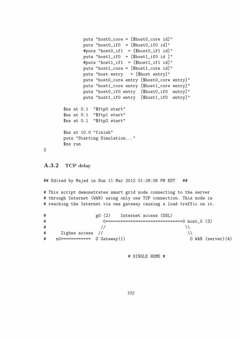
puts "host0_core = [$host0_core id]"
puts "host0_if0 = [$host0_if0 id]"
#puts "host0_if1 = [$host0_if1 id]"
puts "host1_if0 = [$host1_if0 id ]"
#puts "host1_if1 = [$host1_if1 id]"
puts "host1_core = [$host1_core id]"
puts "host entry = [$host entry]"
puts "host0_core entry [$host0_core entry]"
puts "host1_core entry [$host1_core entry]"
puts "host0_if0 entry [$host0_if0 entry]"
puts "host1_if0 entry [$host1_if0 entry]"
$ns at 0.1 "$ftp0 start"
$ns at 0.1 "$ftp1 start"
$ns at 0.1 "$ftp2 start"
$ns at 10.0 "finish"
puts "Starting Simulation..."
$ns run
2
A.3.2 TCP delay
## Edited by Majed in Sun 11 Mar 2012 01:28:06 PM EDT ##
# This script demonstrates smart grid node connecting to the server
# through Internet (WAN) using only one TCP connection. This node is
# reaching the Internet via one gateway causing a load traffic on it.
# g0 (2) Internet access (DSL)
# 0===============================0 host_0 (3)
# // \\
# Zigbee access // \\
# n0============ O Gateway(1) O WAN (server)(4)
# SINGLE HOME #
102
Trace set show_tcphdr_ 0
# grep "d" all.tr > drop.txt -> to output the dropped packets
# into a text file
#Agent/TCP set tcpip_base_hdr_size_ 40
#Agent/TCPSink set packetSize_ 20
#Agent/TCP set window_ 20
#Agent/TCP set packetSize_ 1100
#Agent/TCP set cwnd_ 0
#Agent/TCP set ts_resetRTO_ false
#Agent/TCP set windowInit_ 1500
set ns_ [new Simulator]
#$ns_ rtproto DV
$ns_ color 0 Red
$ns_ color 1 Green
$ns_ color 2 Blue
$ns_ color 3 Gray
set nf [open tcpsg.nam w]
$ns_ namtrace-all $nf
set allchan [open TCPsingle.tr w]
$ns_ trace-all $allchan
# Creating all nodes
set n0 [$ns_ node]
$n0 label n0
$n0 color Red
set gateway [$ns_ node]
$gateway label Gateway
$gateway color Gray
set g0 [$ns_ node]
$g0 label g0
$g0 color Purple
set host_0 [$ns_ node]
$host_0 label host_0
103

$host_0 color black
set wan [$ns_ node]
$wan label WAN
$wan color Blue
# Creating the links and topolgy
# Connections data rates starting from an appliance equipped
# with a Zigbee passing through a DSL and 3G to the server
# (1)create a link between n0 & gateway (Zigbee access)
$ns_ duplex-link $n0 $gateway 250Kb 200ms DropTail
# Primary connection
# (2.1) DSL conneciton as a max upload of cable internet (as
# the most used connection type in Canada)
$ns_ duplex-link $gateway $g0 2Mb 60ms DropTail
$ns_ duplex-link $g0 $host_0 2Mb 60ms DropTail
$ns_ duplex-link $host_0 $wan 2Mb 60ms DropTail
# Nodes locations_ in NAM
$ns_ duplex-link-op $n0 $gateway orient right
$ns_ duplex-link-op $gateway $g0 orient right-up
$ns_ duplex-link-op $g0 $host_0 orient right
$ns_ duplex-link-op $host_0 $wan orient right-down
# We apply error on the link between in the gateway to trigger
# a retransmission
set em [new ErrorModel]
$em set rate_ 0.1
$em unit pkt
$em ranvar [new RandomVariable/Uniform]
$em drop-target [new Agent/Null]
#$ns_ at 6 "$ns_ link-lossmodel $em $host_0 $wan"
#$ns_ at 1.5 "$ns_ link-lossmodel $em $g0 $host_0"
$ns_ at .5 "$ns_ link-lossmodel $em $gateway $g0"
#Setup a TCP connection for n0
set tcp0 [new Agent/TCP]
$ns_ attach-agent $gateway $tcp0
#$tcp0 set packetSize_ 1000
104

$tcp0 set fid_ 0
#$tcp0 set cwnd_
$tcp0 set window_ 2000
#$tcp0 set windowInit_ 200
set trace_ch [open trace.tcp0 w]
$tcp0 set trace_all_ 0
$tcp0 set ndatabytes_
$tcp0 trace cwnd_
$tcp0 trace dupacks_
$tcp0 trace rtt_
$tcp0 trace ack_
$tcp0 trace srtt_
$tcp0 trace rttvar_
$tcp0 attach $trace_ch
set ftp0 [new Application/FTP]
$ftp0 attach-agent $tcp0
#$ftp0 set packetSize_ 1000
#$ftp0 set interval_ 0.005
#$ftp0 set type_ CBR
$ftp0 set class_ 0
set ftp1 [new Application/FTP]
$ftp1 attach-agent $tcp0
#$ftp1 set packetSize_ 1000
#$cbr0 set interval_ 0.005
$ftp1 set class_ 1
set ftp2 [new Application/FTP]
$ftp2 attach-agent $tcp0
#$ftp2 set packetSize_ 1000
# Creating the sinks agents at wan
set dstn0 [new Agent/TCPSink]
#$dstn0 set window_ 1500
$ns_ attach-agent $wan $dstn0
# Attach the created agents to TCP sources
$ns_ connect $tcp0 $dstn0
105

puts "n0 = [$n0 id]"
puts "Gateway = [$gateway id]"
puts "WAN = [$wan id]"
# puts "host_1 = [$host_1 id]"
puts "host_0 = [$host_0 id]"
puts "g0 = [$g0 id]"
#puts "g1 = [$g1 id]"
# A trace file for the two nodes(gateway $wan) link
# set qfl [open qf.tr w]
#$ns_ trace-queue $gateway $wan $qfl
# To monitor a specific link
set slink0 [$ns_ link $gateway $g0]
# Create monitor
set fmon0 [$ns_ makeflowmon Fid]
$ns_ attach-fmon $slink0 $fmon0
set slink1 [$ns_ link $gateway $g1]
# Create monitor
# set fmon1 [$ns_ makeflowmon Fid]
# $ns_ attach-fmon $slink1 $fmon1
set old_data 0
#set trace_file [open trace_file.out w]
#Define the finish procedure that closes the trace files and starts
# nam and xgraph
proc finish {} {
global ns_ nf allchan fmon0 fmon1
$ns_ flush-trace
#Close the trace files
close $nf
puts " no. of link0 packet dropped =[$fmon0 set pdrops_] "
exec awk {
{
if ($1=="r" && $4=="4" && $6=="1040" ) {
old_data=old_data + $6
print $2,tab,tab,old_data*8/$2/1000
}
}
106

} TCPsingle.tr > TCPthroughputN.data
exec awk {
{
if ($1=="r" && $4=="3" && $6=="1040") {
#old_data=old_data + $6
print $2,tab,tab,$11
}
}
} TCPsingle.tr > TCPTSN.data
exec awk {
{
if (($1=="d" && $5=="tcp" || $1=="d" && $5=="ack")) {
#drop_data=old_data + $6
print $2,tab,$11,tab,tab,$8
}
}
} TCPsingle.tr > TCPdrop.data
exec awk {
{
if ($7=="---A---") {
#drop_data=old_data + $6
print $2,tab,$11
}
}
} TCPsingle.tr > CWNDTCP.data
# Call xgraph plotting program to plot throughput vs time
# exec xgraph -t (TCP packet drop) -nl -M -x time -y TSN&drop.data
# TCPdrop.data -geometry 800x500 &
exit 0
}
$ns_ at 0.1 "$ftp0 start"
$ns_ at 0.1 "$ftp1 start"
$ns_ at 0.1 "$ftp2 start"
$ns_ at 10 "finish"
puts "Starting Simulation..."
$ns_ run
107

References
[1] Department of Energy (USA)-Office of Electric Transmission and Distribution,
A white paper in, Grid 2030: A National Vision for Electricity’s Second 100
years, July 2003.
[2] E. Santacana, G. Rackliffe, L. Tang, and X. Feng, A white paper in, Getting
Smart, March/April. 2010.
[3] R. Stewart, Q. Xie, K. Morneault, C. Sharp, H. Schwarzbauer, T. Taylor, I. Ry-
tina, M. Kalla, L. Zhang, and V. Paxson, RFC2960 Stream Control Transmission
Protocol, October 2000.
[4] R. Stewart, RFC4960 Stream Control Transmission Protocol, September 2007.
[5] Sonomainnovation, A white paper in, Smart Grid Communications Architectural
Framework, August 31 2009.
[6] The 3rd Generation Partnership Project (3GPP), High-Speed Packet Access
(HSPA), 2012.
[7] S. Kim, S. Koh, and Y. Kim, Performance of SCTP for IPTV applications,
In Advanced Communication Technology, The 9th International Conference on,
volume 3, pages 2176 –2180, Feb. 2007.
108
[8] S. Zeadally, H. Moustafa, and F. Siddiqui, Internet Protocol Television (IPTV):
Architecture, trends, and challenges, Systems Journal IEEE, 5(4):518 –527, Dec.
2011.
[9] M. Happenhofer and P. Reichl, Measurement-based analysis of head-of-line
blocking for sip over TCP, In Modeling, Analysis Simulation of Computer and
Telecommunication Systems (MASCOTS), 2010 IEEE International Symposium
on, pages 244 –253, Aug. 2010.
[10] J. Rosenberg, H. Schulzrinne, G. Camarillo, A. Johnston, J. Peterson, R. Sparks,
M. Handley, and E. Schooler, RFC3261 SIP: Session Initiation Protocol, June
2002.
[11] J. Rosenberg, H. Schulzrinne, and G. Camarillo, RFC4168 The Stream Control
Transmission Protocol (SCTP) as a Transport for the Session Initiation Protocol
(SIP), October 2005.
[12] A. Hasswa, N. Nasser, and H. Hassanein, Performance evaluation of a transport
layer solution for seamless vertical mobility, In Wireless Networks, Communica-
tions and Mobile Computing, 2005 International Conference on, volume 1, pages
576 – 581 vol.1, June 2005.
[13] C. Puttamadappa, G.R. Veerendra, and K.S. Nandini Prasad, Mobile hosts
interaction over integrated ip and wireless ad hoc networks, In International As-
sociation of Computer Science and Information Technology - Spring Conference
IACSITSC ’09. , pages 155–159, April 2009.
[14] K. Grinnemo, T. Andersson, and A. Brunstrom, Performance Benefits of Avoid-
ing Head-of-Line Blocking in SCTP, In Proceedings of the Joint International
109

Conference on Autonomic and Autonomous Systems and International Confer-
ence on Networking and Services (ICAS/ICNS 2005)
[15] Z. Fan, P. Kulkarni, S. Gormus, C. Efthymiou, G. Kalogriddis, M. Sooriyaban-
dara, Z. Zhu, S. Lambotharan, and W. Chin, Smart Grid Communications:
overview of Research Challenges, Solutions, and Standardization Activities, In
Communications Surveys and Tutorials IEEE, 11 January 2012.
[16] A. Tanenbaum, Computer Networks 4th edition, Prentice Hall Professional
Technical Reference, 2002.
[17] P. Sinha, Distributed Operating Systems: Concepts and Design, Wiley-IEEE
Press, 1997.
[18] J. Iyengar, P. Amer, and R. Stewart, Concurrent Multipath Transfer Using SCTP
Multihoming Over Independent End-to-End Paths, Oct. 2006.
[19] D. Leeds, A white paper in, The Smart Grid in 2010: Market Segments,
Applications and Industry Players, July 2009.
[20] University of Delaware, Vehicle-to-Grid, 2011.
[21] J. Cupp and M. Beehler, Implementing Smart Grid Communications,2008 Avail-
able in http://www.smartgridnews.com/artman/uploads/1/article-smartgrid-
part2-084.pdf
[22] B. Gohn, Smart Grid Communications Architecture, April 15 2011, Avail-
able in http://www.pikeresearch.com/blog/articles/smart-grid-communications-
architecture
[23] T. Lewis, Critical Infrastructure Protection in Homeland Security: Defending a
Networked Nation, April 2006, Wiley and Sons 486 pages
110

[24] A TROPOS NETWORKS, White Paper in, Networking the Smart Grid, 2010,
Available in http://www.tropos.com/pdf/whitepapers/SmartGridWP A7.pdf
[25] Wikipedia, SCTP packet structure, 30 September 2011, Available in
http://en.wikipedia.org/wiki/SCTP packet structure
[26] R. Stewart and P. Amer, Why is SCTP needed given TCP and UDP are widely
available?, In Internet Society, 10 September 2007.
[27] B. Leiba., P. Natarajan, F. Baker, P. Amer and J. Leighton, SCTP : Why, What,
and How, IEEE Computer Society, September/October 2009.
[28] T. Dreibholz, E. Rathgeb, I. Rngeler, R. Seggelmann, M. Txen and R. Stewart,
Stream Control Transmission Protocol: Past, Current, and Future Standardiza-
tion Activities, IEEE Communications Magazine, April 2011.
[29] I. Rodrguez, Stream Control Transmission Protocol The design of a new reliable
transport protocol for IP networks, February 2002, Master’s Thesis, 12 February,
2002, Available in http://www.sctp.org/IvanAriasRodriguezMastersThesis.pdf
[30] S. Fu and M. Atiquzzaman , SCTP: State of the Art in Research,Products, and
Technical Challenges, IEEE Communications Magazine , April 2004.
[31] Information Sciences Institute ISI, Network Simulator2, Available in
http://www.isi.edu/nsnam/ns/
[32] J. Chung and M. Claypool, Network Simulator by Example, Available in
http://nile.wpi.edu/NS/
[33] OPNET Technologies Inc., OpNet modular, Available in
http://www.opnet.com/solutions/network rd/modeler.html
111

[34] Omnicor Technical, NetDisturb simulator, Available in
http://www.omnicor.com/network impairment simulators.aspx
[35] Scalable Network Technologies, QualNet simulator, Available in
http://www.scalable-networks.com/products/qualnet/
[36] A. Varga, OMNet++ simulator, Available in http://www.omnetpp.org/
[37] A. Varga and R. Hornig, An overview of the omnet++ simulation environ-
ment, In Simutools ’08: Proceedings of the 1st international conference on Sim-
ulation tools and techniques for communications, networks and systems work-
shops, pages 1–10. ICST (Institute for Computer Sciences), Social-Informatics
and Telecommunications Engineering, 2008.
[38] A. Ogielski and D. Nicol and J. Cowie, Scalable Simulation Framework, Available
in http://www.ssfnet.org/
[39] J. Cowie and D. Nicol and A. Ogielski, Modeling the global Internet, Computing
in Science Engineering, Jan/Feb 1999, 1, 42 -50.
[40] G. Riley and A. Park, Parallel/Distributed Network Simulator, Available in
http://www.cc.gatech.edu/computing/compass/pdns/index.html
[41] G. Riley, Georgia Tech Network Simulator, Available in
http://www.ece.gatech.edu/research/labs/MANIACS/GTNetS/
[42] N. Binkert, R. Dreslinski, L. Hsu, K. Lim, A. Saidi, and S. Reinhardt, The m5
Simulator: Modeling networked systems, IEEE Micro, 26:52–60, 2006.
[43] N. Binkert, E. Hallnor, and S. Reinhard, Network-oriented full-system simu-
lation using m5, Sixth Workshop on Computer Architecture Evaluation using
Commercial Workloads on, Feb 2003.
112

[44] L. Begg, W. Liu, K. Pawlikowski, S. Perera, and H Sirisena, Survey of Simulators
of Next Generation Networks for Studying Service Availability and Resilience,
February 5 2006.
[45] Cornell University and University of California, REAL network simulator, Avail-
able in http://www.cs.cornell.edu/skeshav/real/overview.html
[46] Defense Advanced Research Projects Agency, NS2 supporter, Available in
http://www.darpa.mil/
[47] Virtual Inter Network Testbed funded by DARPA, NS2 builder, Available in
http://www.isi.edu/nsnam/vint/index.html
[48] John Heidemann, Deborah Estrin, Ramesh Govindan, and Ashish Goel, , NS2
builder, Available in http://www.isi.edu/saman/index.html
[49] Collaborative Simulation for Education and Research, NS2 applier, Available in
http://www.isi.edu/conser/index.html
[50] International Computer Science Institute. NS2 applier, Available in
http://www.icir.org/
[51] Kevin Fall and Kannan Varadhan, NS2 The VINT Manual, Available in
http://isi.edu/nsnam/ns/doc/index.html
[52] T. Issariyakul and E. Hossain, Introduction to Network Simulator NS2, Springer,
2011.
[53] Information Sciences Institute ISI, SCTP trace file format, Available in
http://www.isi.edu/nsnam/ns/doc/node447.html
[54] Information Sciences Institute ISI, TCP trace file format, Available in
http://www.isi.edu/nsnam/ns/doc/node289.html
113
[55] C. Flynt, Tcl/Tk, A Developer’s Guide, 2nd Edition, Morgan Kaufmann Pub-
lishers, 759 pages 05 May 2003.
[56] B. Welch, K. Jones, and J. Hobbs, Practical Programming in Tcl and Tk, Avail-
able in http://www.tcl.tk/doc/
[57] National Institute of Standards and Technology NIST, Available in
http://www.nist.gov
[58] J. Iyengar, P. Amer, and R. Stewart, Concurrent multipath transfer using SCTP
multihoming over independent end-to-end paths, Networking, IEEE/ACM Trans.
, 14(5):951 –964, Oct, 2006.
[59] Red Hat Inc., Cygwin, Available in http://www.cygwin.com/
[60] Information Sciences Institute, Network Animator NAM, Available in
http://isi.edu/nsnam/nam/
[61] A. Aho, P. Weinberger, and B. Kernighan, Awk, Available in http://awk.info/
[62] D. Harrison, P. Walker, and VINT project, Xgraph, Available in
http://www.isi.edu/nsnam/xgraph/index.html
[63] T. Williams and C. Kelley, Gnuplut, Available in http://www.gnuplot.info/
[64] A. Brown and M. Kolberg, Peer to peer network simulation 1st edition, January
27 2006.
[65] K. Wehrle, M. Gnes, and J. Gross, Modeling and Tools for Network Simulation,
1st Edition, Springer, 2010.
[66] B. Gohn and C. Wheelock, A white paper in, Smart Grid: Ten Trends to Watch
in 2011 and Beyond, Research report, Q4 2010.
114
[67] M. Becke, T. Dreibholz, J. Iyengar Franklin, Marshall, P. Natarajan, and
M. Tuexen, Load sharing for the stream control transmission protocol (SCTP),
”irtf-p2prg-core-simulators-00.txt”, July 3 2011.
[68] C. Queiroz, A. Mahmood, and Z. Tar, SCADASim: A Framework for Building
SCADA Simulations, IEEE Trans. Smart Grid, VOL. 2, NO. 4, December 2011.
115


