
PARADISO
COMMENTARY BOX WITH DANTE NETWORK AUDIO & ANALOGUE I/O
PRODUCT DETAILS
6 BROOKS PLACE, MAIDSTONE, KENT, ME14 1HE. ENGLAND. TEL: +44 (0) 1622 753662 Visit our Website at www.glensound.com FAX: +44 (0) 1622 762330

Page 2 of 56
Glensound Electronics Ltd
Thank you for choosing a new Glensound product.
All rights reserved.
Information contained in this manual is subject to change without notice, if in doubt please contact us for the latest product information.
If you need any help with the product then we can be contacted at:
Glensound Electronics Ltd
1 – 6 Brooks Place
Maidstone
Kent ME14 1HE
United Kingdom
Telephone: +44 (0) 1622 753662
Fax: +44 (0) 1622 762330
EMAIL ADDRESSES
General enquires: [email protected]
Technical enquires: [email protected]
Sales enquires: [email protected]

Page 3 of 56
PRODUCT WARRANTY:
All equipment is fully tested before dispatch and carefully designed to provide you with trouble free use for many years.
We have a policy of supporting products for as long as possible and guarantee to be able to support your product for a minimum of 10 years.
For a period of one year after the goods have been despatched the Company will guarantee the goods against any defect developing after proper use providing such defects arise solely from faulty materials or
workmanship and that the Customer shall return the goods to the Company’s works or their local dealer.
All non-wear parts are guaranteed for 2 years after despatch and any defect developing after proper use from faulty materials or workmanship will be repaired under this warranty providing the Customer returns the
goods to the Company's works or their local dealer.

Page 4 of 56
CE
EU DECLARATION OF CONFORMITY FOR:
PARADISO DanteTM / AES67 Network Commentary Box
This declaration of conformity is issued under the sole responsibility of the manufacturer.
This equipment is manufactured by Glensound Electronics Ltd of Brooks
Place Maidstone Kent ME14 1HE is CE marked and conforms to the following Union harmonisation legislation:
Low Voltage Directive: EN60065 and EN62368-1:2014
Emissions: BS EN55032:2015
Immunity: BS EN55035:2017
Signed for and on behalf of Glensound Electronics Ltd.
Gavin Davis, Managing Director Maidstone, Kent, England
Date: 07/02/2018
Page 5 of 56
RoHS DIRECTIVE
RoHS 2 Directive 2011/65/EU restricts the use of the hazardous substances listed below in electrical and electronic equipment.
This product conforms to the above directive and for this purposes, the maximum concentration values of the restricted substances by weight in homogenous materials are:
Lead 0.1%
Mercury 0.1%
Hexavalent Chromium 0.1%
Polybrominated Biphenyls 0.1%
Polybrominated Diphenyl Ethers
0.1%
Cadmium 0.01%

Page 6 of 56
WASTE ELECTRICAL AND ELECTRONIC EQUIPMENT REGULATIONS 2006 (WEEE)
Glensound Electronics Ltd is registered for business to business sales of WEEE in the UK our registration number is:
WEE/JJ0074UR

Page 7 of 56
GLENSOUND PARADISO
Handbook Contents
Issue 6.1
PRODUCT WARRANTY: ............................................................................................................................... 3
OVERVIEW .................................................................................................................................................... 8
PANEL LAYOUT & FUNCTIONS ................................................................................................................. 9
Rear Panel.................................................................................................................................................. 9
Top Panel ................................................................................................................................................. 11
Front Panel ............................................................................................................................................... 13
WINDOWS 10 REMOTE CONTROL APPLICATION .................................................................................. 14
First Time App Installation ....................................................................................................................... 15
Updating A Previously Installed App ...................................................................................................... 16
USING THE APP .......................................................................................................................................... 17
General ..................................................................................................................................................... 17
Compressors & Disabling Hardware Gain Controls .............................................................................. 19
Presets & Loading/ Exporting Configurations ........................................................................................ 20
Entering Configuration Menus ................................................................................................................ 21
Pots & Buttons ......................................................................................................................................... 22
Button Relations ....................................................................................................................................... 23
DC Inputs .................................................................................................................................................. 24
DC Inputs Further Information ................................................................................................................ 25
DC Outputs ............................................................................................................................................... 27
Audio Mixer .............................................................................................................................................. 28
Call Alerts ................................................................................................................................................. 33
Restore Factory Defaults......................................................................................................................... 34
FACTORY PRESET MIXING CONFIGURATION ....................................................................................... 35
FIXED AUDIO MIXING CIRCUITS ............................................................................................................. 41
TEST TONE .................................................................................................................................................. 41
CONNECTING THE PARADISO TO A DANTE NETWORK ...................................................................... 42
Getting Dante Controller .......................................................................................................................... 42
Connecting Paradisos To The Network ................................................................................................. 42
Audio Over IP Network ............................................................................................................................ 42
Running Dante Controller ........................................................................................................................ 43
Dante Controller TIP ................................................................................................................................ 43
Device Not Showing Up In Dante Controller .......................................................................................... 44
UPDATING FIRMWARE.............................................................................................................................. 45
UPDATING THE BROOKLYN MODULE ................................................................................................... 48
REFRESHING ePAPER DISPLAYS ............................................................................................................. 49
AES67 MODE ............................................................................................................................................... 51
WIRING INFORMATION ............................................................................................................................. 54
XLR & JACK Wiring ................................................................................................................................. 54
D9 Wiring & Loop Interconnecting To External Equipment .................................................................. 55
SPECIFICATIONS ........................................................................................................................................ 56

Page 8 of 56
OVERVIEW The Glensound Paradiso is a commentator’s box for 3 commentators. It can be used by itself to provide the commentary facilities alongside an OB truck for small events, or multiple Paradisos can be used at large events that require worldwide broadcast coverage. The Paradiso is designed to connect to a Dante audio network, with the added advantage of having multiple local analogue audio inputs & outputs available for local or backup circuits. The unit provides all the talkback and monitoring circuits required by the commentators whilst incorporating a very high quality microphone amplifiers and compressor limiter circuits designed specifically for the requirements of commentators equipment. The audio inputs and outputs of the Inferno are Dante network audio circuits. Dante network audio is a common protocol for distributing high quality linear audio over standard IP networks and it is widely used by many audio equipment manufacturers. The Glensound Paradiso’s Dante audio interface will be compatible with any other manufacturers Dante audio interface. Further details of Dante network audio can be found at www.audinate.com Being designed for live on-air broadcast applications the Glensound Paradiso has been designed with multiple redundancy capabilities. It has 4 possible sources of power (Mains, 2 x PoE & 1 external DC) and it also has fully redundant network connections for both Copper & Fibre circuits. The Paradiso has been designed to be intuitive & easy to use for Commentators who would rather be talking about the game than working out how the equipment works. It is also built to our exacting rugged and robust standard to make it a reliable piece of broadcast equipoment for the busy engineer.

Page 9 of 56
PANEL LAYOUT & FUNCTIONS
PLEASE NOTE AS THE UNIT IS CONFIGURABLE IT IS POSIBLE TO CHANGE THE OPERATION OF SOME OF THE CONTROLS SHOWN HERE. THEREFORE THE FOLLOWING IS MEANT AS A GUIDE ONLY.
Rear Panel
1. IEC Mains Inlet
3 pin IEC Mains inlet accepting a mains input range of 100 – 240 VAC. ********THIS UNIT MUST BE EARTHED********
2. Analogue Audio Outputs
Standard balanced audio outputs, fed internally from the DSP. These can be completely independent to the Dante audio circuits and do not require the Dante network to operate.
3. Fibre Network Interface
Primary & Secondary Dante network fibre interfaces on Neutrik Opticon connectors. By default these are fed from an internal Single Mode transceiver (Multi Mode is available as an option).
5. Analogue Audio Inputs
6. Identify & Reset Buttons 7. USB 1
8. Copper Network Connections
9. USB 2
1. Mains In 2. Analogue Audio Out
10. DC IN
3. Fibre Network Connections
4. AES I/O and GPIO

Page 10 of 56
4. AES I/O & GPIO
This D9 socket provides 1 x AES3 input & output (2 channels of audio). The sample rate of this AES3 circuit matches (and is locked to) the Dante network. A Pair of general purpose outputs (GPO) and a pair of general purpose inputs (GPI) are also provided. The outputs are ‘open collector’….see wiring information for examples of interconnection.
5. Analogue Audio Inputs
Standard balanced audio inputs, fed internally to the DSP. These are completely independent to the Dante network.
6. Identify & Reset Buttons
Currently used for updating software. Only use if advised by technical support.
7. USB 1
USB 1 socket is used for updating firmware to the main processor and should only be used if advised by technical support.
8. Copper Network Connections
These primary & secondary Neutrik Ethercon connectors provide the copper network interface.
9. USB 2
USB 2 socket is used for updating firmware to the processor controlling the front panel and should only be used if advised by technical support.
10. DC IN
This is a 2 pin barrel type DC input connector. The centre pin is 2.5mm. It is wired centre pin + Volts. It is designed to accept a + volt DC input between 9 and 15 volts. The connector has a barrel locking mechanism allowing specialist locking barrel connectors to be used, a suitable mating part is manufactured by KYCON and their part number is KLDX-PA-0202-B-LT
Page 11 of 56
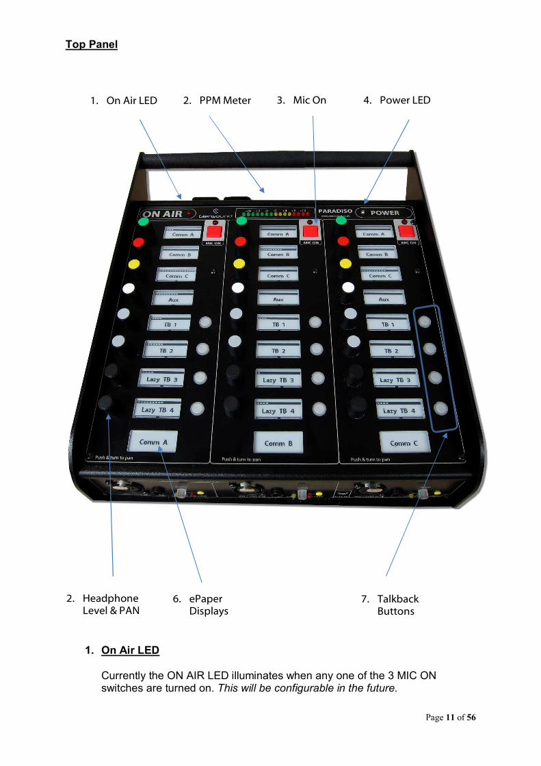
Top Panel
1. On Air LED Currently the ON AIR LED illuminates when any one of the 3 MIC ON switches are turned on. This will be configurable in the future.
1. On Air LED 2. PPM Meter 3. Mic On 4. Power LED
2. Headphone Level & PAN
6. ePaper Displays
7. Talkback Buttons

Page 12 of 56
2. PPM Meter
Normally the Peak Programme Meter (PPM) shows the output level of the mix of the 3 commentators’ microphones. If the gain is adjusted on any of the commenttaors microphone inputs then the PPM automatically solos this input. This will be configurable in the future.
3. Mic On
These buttons turn the commentators’ microphone on/off. The operation of this button will be configurable in the future.
4. Power On LED
This bright blue LED indicates when the unit is connected to a suitable power source and when the internal main processor is working.
5. Headphone Level & PAN Control
The 24 coloured knobs provide level and panning of the associated input audio source. Turning the knob clockwise/ anticlockwise increases/ decreases the level (Note at the top of the ePaper display a visual indication is provided of the position of the control). To PAN the audio source between the left ear/ right ear of the commentators headphones then the knob should be simultaneously pushed down and turned clockwise/ anticlockwise. The bottom section of the ePaper display indicates the current panned position.
6. ePaper Displays
The ePaper displays are sometimes called eInk and are like the displays on a Kindle ebook reader. Each display provides information that would normally be associated with the headphone level & pan control and the talkback switch. The graffiti provides an indication of what the associated audio source/ destination is (currently these are fixed but the in the future the displayed graffiti will be adjustable). The top ‘bar’ of the display provides a visual indication of the position of the associated volume control and the buttom ‘bar’ of the display provides a visual indication of the current panned position of the source.
7. Talkback Buttons
These talkback buttons route the commentators’ microphone to the associated talkback output. Currently the operation of this button and the routing are fixed, but both will be assignable in the future.
Page 13 of 56
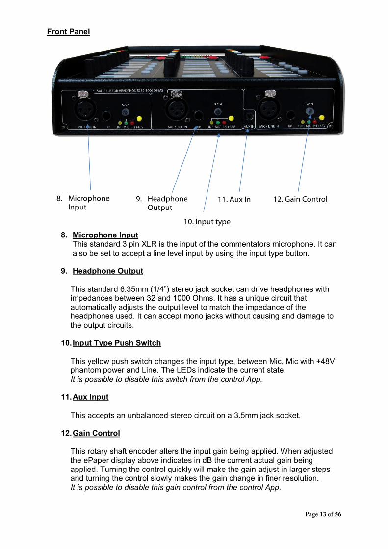
Front Panel
8. Microphone Input This standard 3 pin XLR is the input of the commentators microphone. It can also be set to accept a line level input by using the input type button.
9. Headphone Output
This standard 6.35mm (1/4”) stereo jack socket can drive headphones with impedances between 32 and 1000 Ohms. It has a unique circuit that automatically adjusts the output level to match the impedance of the headphones used. It can accept mono jacks without causing and damage to the output circuits.
10. Input Type Push Switch
This yellow push switch changes the input type, between Mic, Mic with +48V phantom power and Line. The LEDs indicate the current state. It is possible to disable this switch from the control App.
11. Aux Input
This accepts an unbalanced stereo circuit on a 3.5mm jack socket.
12. Gain Control
This rotary shaft encoder alters the input gain being applied. When adjusted the ePaper display above indicates in dB the current actual gain being applied. Turning the control quickly will make the gain adjust in larger steps and turning the control slowly makes the gain change in finer resolution. It is possible to disable this gain control from the control App.
8. Microphone Input
9. Headphone Output
10. Input type
11. Aux In 12. Gain Control
Page 14 of 56
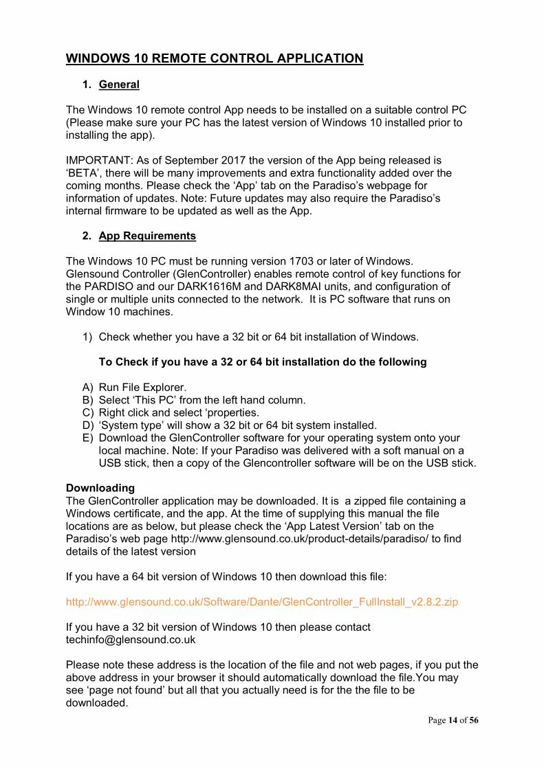
WINDOWS 10 REMOTE CONTROL APPLICATION
1. General
The Windows 10 remote control App needs to be installed on a suitable control PC (Please make sure your PC has the latest version of Windows 10 installed prior to installing the app). IMPORTANT: As of September 2017 the version of the App being released is ‘BETA’, there will be many improvements and extra functionality added over the coming months. Please check the ‘App’ tab on the Paradiso’s webpage for information of updates. Note: Future updates may also require the Paradiso’s internal firmware to be updated as well as the App.
2. App Requirements
The Windows 10 PC must be running version 1703 or later of Windows. Glensound Controller (GlenController) enables remote control of key functions for the PARDISO and our DARK1616M and DARK8MAI units, and configuration of single or multiple units connected to the network. It is PC software that runs on Window 10 machines.
1) Check whether you have a 32 bit or 64 bit installation of Windows. To Check if you have a 32 or 64 bit installation do the following
A) Run File Explorer. B) Select ‘This PC’ from the left hand column. C) Right click and select ‘properties. D) ‘System type’ will show a 32 bit or 64 bit system installed. E) Download the GlenController software for your operating system onto your
local machine. Note: If your Paradiso was delivered with a soft manual on a USB stick, then a copy of the Glencontroller software will be on the USB stick.
Downloading
The GlenController application may be downloaded. It is a zipped file containing a Windows certificate, and the app. At the time of supplying this manual the file locations are as below, but please check the ‘App Latest Version’ tab on the Paradiso’s web page http://www.glensound.co.uk/product-details/paradiso/ to find details of the latest version If you have a 64 bit version of Windows 10 then download this file: http://www.glensound.co.uk/Software/Dante/GlenController_FullInstall_v2.8.2.zip If you have a 32 bit version of Windows 10 then please contact [email protected] Please note these address is the location of the file and not web pages, if you put the above address in your browser it should automatically download the file.You may see ‘page not found’ but all that you actually need is for the the file to be downloaded.

Page 15 of 56
First Time App Installation
Make sure the GlenController download files are in a folder on your local machine and unzip the files to a know location. Installation of GlenController is a two stage process as all Windows 10 applications must have a digital certificate. If this is the first time you have installed Glensound applications, then you must first load the Glensound App Certificate. This will allow you to install GlenController and any further Glensound Windows 10 applications. If you already have the Glensound digital certificate you can go straight to Stage 2. Stage 1 – Check/ Enable Windows ‘Sideloading Apps’
The App uses a Windows 10 feature called Sideloading Apps (as do many other Apps), this feature is probably already enabled on your machine but we suggest that you check/ enable it prior to trying to load the App.
1) Open Settings and select Update & Security 2) Select For developers and make sure that Sideload apps is selected 3) If you are turning on Sideload apps for the first time Windows will pop up a
warnings screen, make sure that you are happy to proceed and click Yes Stage 2 – Installing The Certificate
All Windows 10 apps must have a valid certificate. If you have previously installed a Glensound App on your PC then you will already have the certificate installed and can proceed straight to satge 3.
1) Locate and double click the file from the downloaded files.
Stage 3 – Install The App
1) Locate and double click the file ‘GlenController_x.x.xxx_x??.appx from the
downloaded files. (Whereby the x.x.xxx will be the version number and the ?? will be either 64 or 86 depending upon whether you are installing the 64(64) or 32(86) bit version of the App.
Uninstalling GlensoundController
Find the app in the ‘All apps’ list then right-click and select ‘Uninstall’.

Page 16 of 56
Updating A Previously Installed App If you have an earlier version of Glensound Controller installed on your PC, then you should not need to perform a complete new installation to update it. Downloading
The GlenController update file may be downloaded. It is a zipped file. At the time of supplying this manual the file location is: http://www.glensound.co.uk/Software/Dante/GlenController_Upgrade_v2.8.2.zip Please check the ‘App Latest Version’ tab on the Paradiso’s web page http://www.glensound.co.uk/product-details/paradiso/ to find details of the latest version The above file is for 64 bit Windows, If you have a 32 bit version of Windows 10 then please contact [email protected] Please note these address is the location of the file and not web pages, if you put the above address in your browser it should automatically download the file.You may see ‘page not found’ but all that you actually need is for the the file to be downloaded. Make sure the GlenController download files are in a folder on your local machine and unzip the files to a know location. Stage 1 – Install The App
1) Locate and double click the file ‘GlenController_x.x.x.x_x??.appx from the
downloaded files. (Whereby the x.x.x.x will be the version number and the x?? will be either 64 or 86 depending upon whether you are installing the 64(64) or 32(86) bit version of the App.
Page 17 of 56
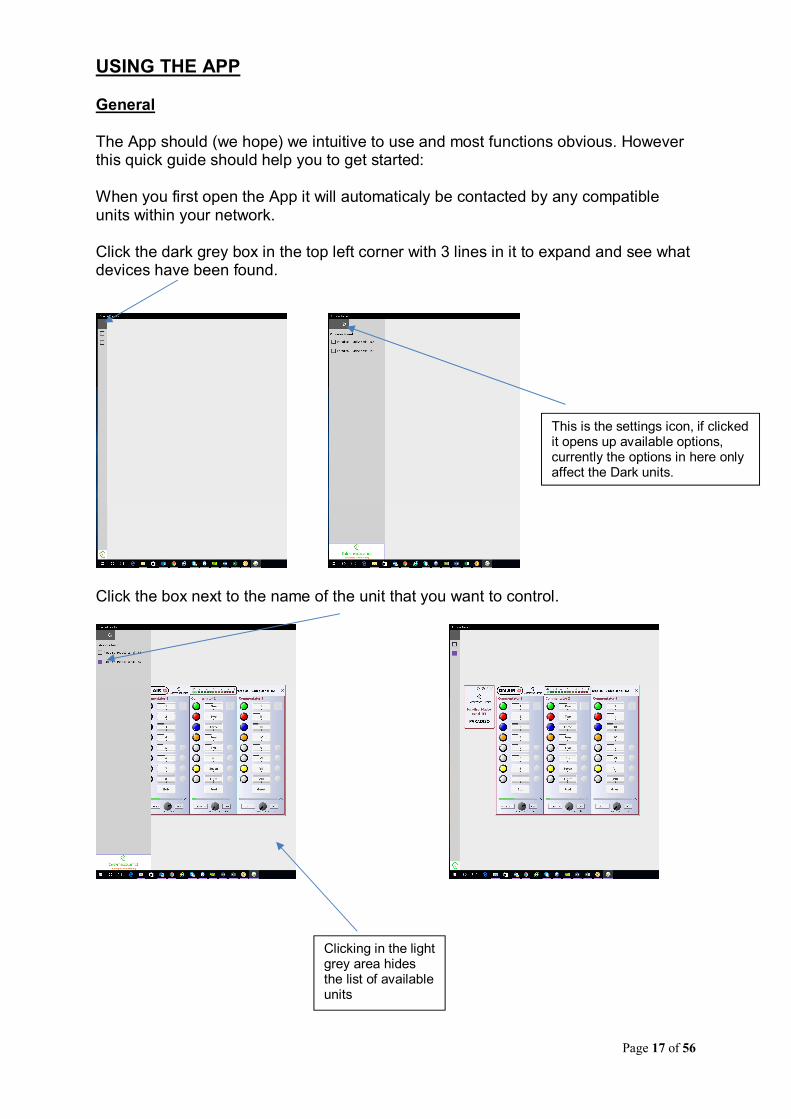
USING THE APP General The App should (we hope) we intuitive to use and most functions obvious. However this quick guide should help you to get started: When you first open the App it will automaticaly be contacted by any compatible units within your network. Click the dark grey box in the top left corner with 3 lines in it to expand and see what devices have been found.
Click the box next to the name of the unit that you want to control.
This is the settings icon, if clicked it opens up available options, currently the options in here only affect the Dark units.
Clicking in the light grey area hides the list of available units

Page 18 of 56
Most operations of the remote control App should be fairly obvious. They all operate in real time in conjunction with the front panel controls, so turning a mic on on the App will illuminate the Mic On LED on the Paradiso and switch the audio circuit on. A few of the less immediately obvious controls are:
Right click in the displays to alter text
You can drag the pan control left/ right but the mouse wheel also adjust the pan
If this writing turns RED then the app has lost communication with the Paradiso
Clicking this arrow hides/ shows the gain controls
Configuration: Clicking this settings button will open configuration options

Page 19 of 56
Compressors & Disabling Hardware Gain Controls
The following options wil the become available:
Whereby ticking or unticking the box next to the functionality description sets the option in real time. Notes: Enable in line mode: If ticked the compressor will be turned on if the input is set to line. Slow decay: This turns off a fast RMS compressor before the more gentle peak compressor. Disable on switched outputs: If ticked the 3 switched outputs that are routed to Dante Outputs 9,10 & 11 from the 3 microphones will have their compressors disabled…..note: The microphone signals to the mixer are always fed through the compressor Lock input mode button: If ticked the front panel input mode push button will be disabled. Lock input gain knob: If ticked the front panel gain control will be disabled.
Click the settings icon next to the gain control in the main screen of the channel to be modified
Page 20 of 56
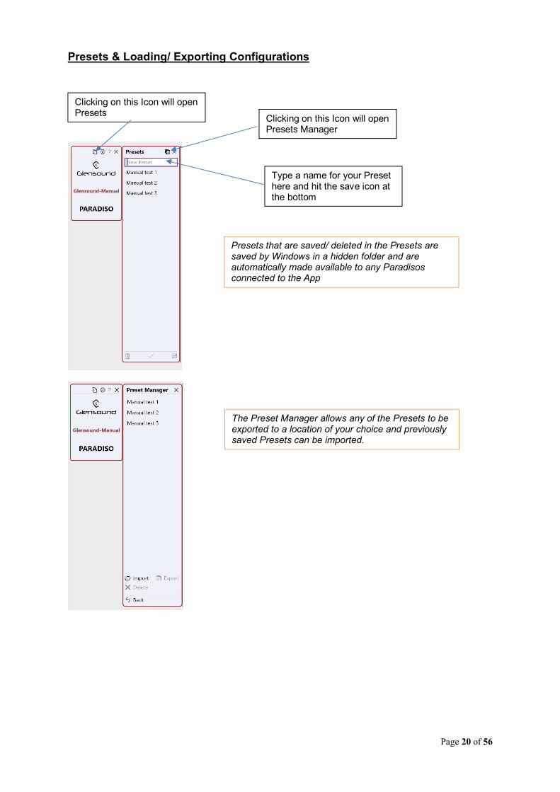
Presets & Loading/ Exporting Configurations
Clicking on this Icon will open Presets
Type a name for your Preset here and hit the save icon at the bottom
Clicking on this Icon will open Presets Manager
Presets that are saved/ deleted in the Presets are saved by Windows in a hidden folder and are automatically made available to any Paradisos connected to the App
The Preset Manager allows any of the Presets to be exported to a location of your choice and previously saved Presets can be imported.
Page 21 of 56
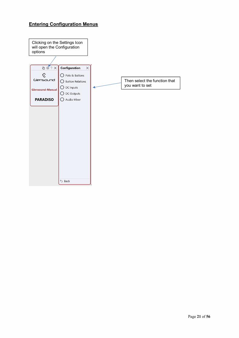
Entering Configuration Menus
Clicking on the Settings Icon will open the Configuration options
Then select the function that you want to set

Page 22 of 56
Pots & Buttons
Under Each Pot there is a switch for allowing that pot to fully attenuate (Full) or to never allow it to fully turn of the audio input (Limited)
Under Each Button there is a drop down option list for setting how you would like the button to operate. ‘Intelligent’ mode requires a short push of the button to toggle between on/off and if the button is pushed and held it will be momentary.
The Pan Function switch enables/ disables the hardware pan function of the front panel controls for the associated headphone mix

Page 23 of 56
Button Relations
1st select the button that you want to setup relationships for
Then using the drop down list under the button that you want to interact with the Controlling button, choose the option that meets your requirements.

Page 24 of 56
DC Inputs
There are 4 GPIO circuits available on the rear panel D connector. Each of the 4 circuits can be set to being either an input OR an output. Turning the DC Outputs on in the DC Outputs configuration will overide the DC Inputs.
1st select which GPI circuit you want to set.
2nd Using the drop down list select how the external switch input will operate.
3rd Using the drop down list under the button that you want the external input to control select the desired action. (please see below for more details)

Page 25 of 56
DC Inputs Further Information
A DC input is active low and has a weak pullup. It can be connected to an external switch that makes contact with GND. Such a switch is called "external button". An external button behaves in the same way as any internal button and can be set to one of the operating modes: - Intelligent - Momentary - Toggling - Cough This way an external button has a logical state, similar to any other button. It is possible to provide feedback about this state by configuring a DC output and connecting a LED. Each external button can be configured to action or override one or more of the internal (front panel) buttons, including the ones that are not physically mounted. An external button can affect any of the internal buttons in the following ways: - Unaffected - Action (emulate the button's press/release) - Override Follow - Override Momentary On - Override Momentary Off - Override On (latch) - Override Off (de-latch) The difference between action and override is that the former is equivalent to the dependent button being pressed/released, while the latter simply forces the button to a given state. Action mode ----------- In the Action mode, the operating mode of the external button is ignored. The dependent button will react to pressing/releasing of the external button, as if it was pressed/released itself, according to its own operating mode. If a dependent button is configured to override other buttons, the relations will be followed and the other buttons will be affected as well. Also, if the button is currently being overridden (locked), then it will not respond to the external button. Override mode ------------- In the Override mode the dependent button is always forced to the desired state and its relations are not followed. - Override Follow The dependent button follows the state of the external button. It is locked all the time (ignores presses of the local or remote button).
Page 26 of 56
- Override Momentary On While the external button is On then the dependent button is locked On. Otherwise it is unlocked and reverts to its original state. - Override Momentary Off While the external button is On then the dependent button is locked Off. Otherwise it is unlocked and reverts to its original state. - Override On (latch) If the dependent button is not in Toggling or Intelligent mode, this is the same as Override Momentary On. Otherwise, while the external button is On, then the dependent button is latched to On. When the external button goes Off, the dependent button remains On and is unlocked. - Override Off (de-latch) If the dependent button is not in Toggling or Intelligent mode, this is the same as Override Momentary Off. Otherwise, while the external button is On then the dependent button is latched to Off. When the external button goes Off, the dependent button remains Off and is unlocked.

Page 27 of 56
DC Outputs
1st select the I/O pin that you want to set as an output and using the software slide switch change it from Input to Output
Then select the button(s) that you want to trigger that output when they are active by sliding their virtual slide switch to Connected.
Page 28 of 56
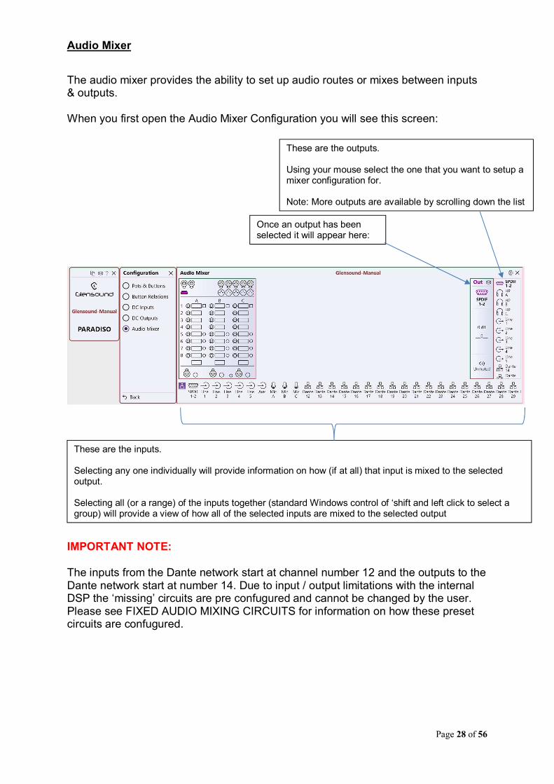
Audio Mixer
The audio mixer provides the ability to set up audio routes or mixes between inputs & outputs. When you first open the Audio Mixer Configuration you will see this screen:
IMPORTANT NOTE: The inputs from the Dante network start at channel number 12 and the outputs to the Dante network start at number 14. Due to input / output limitations with the internal DSP the ‘missing’ circuits are pre confugured and cannot be changed by the user. Please see FIXED AUDIO MIXING CIRCUITS for information on how these preset circuits are confugured.
These are the outputs. Using your mouse select the one that you want to setup a mixer configuration for. Note: More outputs are available by scrolling down the list
Once an output has been selected it will appear here:
These are the inputs. Selecting any one individually will provide information on how (if at all) that input is mixed to the selected output. Selecting all (or a range) of the inputs together (standard Windows control of ‘shift and left click to select a group) will provide a view of how all of the selected inputs are mixed to the selected output

Page 29 of 56
A) The Initial Input Screen
In the below screen shot HP A has been selected as the output and Line Input 1 has been selected to see how its relationship to HP A is currently set.
This shows that the input is Unmuted i.e. its output is being mixed into the selected output
A3 refers to the front panel hardware volume control that is associated with this input
This is a balance control and dragging this bar left or right will move the inputs source to the left or right outputs. Note this control works in real time and can be seen reflected in the ePaper displays
The Volume control works in parallel with the front panel hardware volume control and works in real time
Pressing the Setup Icon changes the input to settings mode, please see next page for more details

Page 30 of 56
B) The Input Channels’ Setting Screen
In the below screenshot the settings Icon has been selected on the top right hand corner of Line Input 1’s channel. This allows configuration of this input to the selected output (in the screenshot belwo this is HP A).
This drop down menu allows a button to be allocated that will turn the audio on/ off
Toggling the speaker Icon mutes (or unmutes) the input to the selected output
The associated hardware volume control is set using this drop down list

Page 31 of 56
C) Input or Output Centric Mixing View
The mixing configuration can be made to work in either an input or output centric mode. Input centric is about quickly seeing where an input is being mixed to. In this mode an input (or several simultaneously) can be selected and these stay in the mixer configuration view until they are deselected. This means that different oputputs can be selected to see if these inputs are being mixed to them. Output centric is about seeing what inputs an output has mixed to it. In this mode all Unmuted inputs are displayed that are being mixed to an output when an output is selected.
Use this speaker Icon to switch between input & output centric modes. When the Icon is highlighted (as shown in the above screenshot) the mixer configuration is working in output centric mode
Page 32 of 56
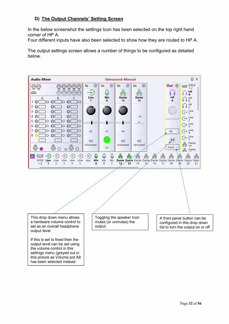
D) The Output Channels’ Setting Screen
In the below screenshot the settings Icon has been selected on the top right hand corner of HP A. Four different inputs have also been selected to show how they are routed to HP A. The output settings screen allows a number of things to be configured as detailed below.
This drop down menu allows a hardware volume control to set as an overall headphone output level. If this is set to fixed then the output level can be set using the volume control in this settings menu (greyed out in this picture as Volume pot A8 has been selected instead.
Toggling the speaker Icon mutes (or unmutes) the output.
A front panel button can be configured in this drop down list to turn the output on or off

Page 33 of 56
Call Alerts
The Call Alert function helps to integrate the Paradiso with our Beatrice Intercom system. The Beatrice Intercom uses an often used industry standard way of sending inband 20kHz tones to trigger a calling function to enable users to attract the attention of one and other. The incoming 20kHz tone is filtered out by a hiQ notch filter so that the commentator cannot hear it. To send a Call Alert the operator must push and hold for more than 2 seconds the headphone volume/ pan control. When a the Paradiso is sending the Call Alert the ePaper display will indicate ‘Calling….’ When a Call Alert is received the associated Talkback Switch will flash (assumming that one is fitted) and the ePaper display will indicate ‘Ring!’
Use these drop down lists to assign the Dante Output (DOUT) Channel that the Call Alert tone will be sent on when operating the above control.
Use these drop down lists to assign the Dante Input (DIN) Channel that a received Call Alert tone will be associated with.

Page 34 of 56
Restore Factory Defaults
In each configuration page there is a settings Icon in the top right hand corner located next to the close ‘X’. Selecting this settings option provides an option for returning the current configuration menu back to factory presets.

Page 35 of 56
FACTORY PRESET MIXING CONFIGURATION
Anaolgue Input 1To Commentators AUX headphone
To Dante Out Channel 3 "Line in 1"
Anaolgue Input 2To Commentators TB 1 headphone
To Dante Out Channel 4 "Line in 2"
Anaolgue Input 3To Commentators TB 2 headphone
To Dante Out Channel 5 "Line in 3"
Anaolgue Input 4To Commentators Lazy TB 3 headphone
To Dante Out Channel 6 "Line in 4"
Anaolgue Input 5To Commentators Lazy TB 4 headphone
To Dante Out Channel 7 "Line in 5"
AES 3 InTo Dante Out Channel 2 "AES3 B"
To Dante Out Channel 1 "AES3 A"
ANALOGUE & AES INPUTS

Page 36 of 56
From Dante Incoming Circuit 12 "AUX A"
From Analogue in 1 (AUX)
From Dante Incoming Circuit 15 "TB1A"
From Analogue in 1 (TB 1)
From Dante Incoming Circuit 18 "TB2A"
From Analogue in 3 (TB 2)
From Dante Incoming Circuit 21 "TB3A"
From Analogue in 4 (Lazy TB 3)
From Dante Incoming Circuit 24 "TB4 A"
From Analogue in 5 (Lazy TB 4)
From Commentator A Mic On
From Commentator B Mic On
From Commentator C Mic On
STEREO HEADPHONES
6.35mm (1/4")
NOTE:
Headphone circuit drawn for simplicity as mono
but in reality it is stereo with pan pots after each
of the 8 level controls
COMMENTATOR A HEADPHONES
STEREO HEADPHONES
6.35mm (1/4")
COMMENTATOR B HEADPHONES
From Dante Incoming Circuit 13 "AUX B"
From Analogue in 1 (AUX)
From Dante Incoming Circuit 16 "TB1B"
From Analogue in 1 (TB 1)
From Dante Incoming Circuit 19 "TB2B"
From Analogue in 3 (TB 2)
From Dante Incoming Circuit 22 "TB3B"
From Analogue in 4 (Lazy TB 3)
From Dante Incoming Circuit 25 "TB4 B"
From Analogue in 5 (Lazy TB 4)
From Commentator A Mic On
From Commentator B Mic On
From Commentator C Mic On
NOTE:
Headphone circuit drawn for simplicity as mono
but in reality it is stereo with pan pots after each
of the 8 level controls

Page 37 of 56
STEREO HEADPHONES
6.35mm (1/4")
COMMENTATOR C HEADPHONES
From Dante Incoming Circuit 14 "AUX C"
From Analogue in 1 (AUX)
From Dante Incoming Circuit 17 "TB1C"
From Analogue in 1 (TB 1)
From Dante Incoming Circuit 20 "TB2C"
From Analogue in 3 (TB 2)
From Dante Incoming Circuit 23 "TB3C"
From Analogue in 4 (Lazy TB 3)
From Dante Incoming Circuit 26 "TB4 C"
From Analogue in 5 (Lazy TB 4)
From Commentator A Mic On
From Commentator B Mic On
From Commentator C Mic On
NOTE:
Headphone circuit drawn for simplicity as mono
but in reality it is stereo with pan pots after each
of the 8 level controls
From Dante Incoming Circuit 8 "W"
From Dante Incoming Circuit 9 "X"
From Dante Incoming Circuit 10 "Y"
From Dante Incoming Circuit 11 "Z"
WXYZ Mixer
To Dante Out Channel 12 "WXYZ Mix"
Page 38 of 56
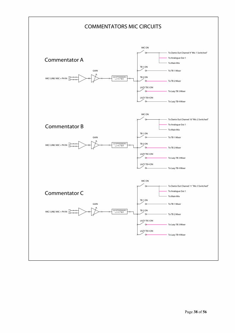
GAIN
MIC/ LINE/ MIC + PH IN
MIC ON
TB 1 ON
TB 2 ON
LAZY TB 3 ON
LAZY TB 4 ON
To Dante Out Channel 9 "Mic 1 Switched"
To Analogue Out 1
To Main Mix
To TB 1 Mixer
To TB 2 Mixer
To Lazy TB 3 Mixer
To Lazy TB 4 Mixer
Commentator A
GAIN
MIC/ LINE/ MIC + PH IN
Commentator B
GAIN
MIC/ LINE/ MIC + PH IN
Commentator C
COMMENTATORS MIC CIRCUITS
MIC ON
TB 1 ON
TB 2 ON
LAZY TB 3 ON
LAZY TB 4 ON
To Dante Out Channel 10 "Mic 2 Switched"
To Analogue Out 1
To Main Mix
To TB 1 Mixer
To TB 2 Mixer
To Lazy TB 3 Mixer
To Lazy TB 4 Mixer
MIC ON
TB 1 ON
TB 2 ON
LAZY TB 3 ON
LAZY TB 4 ON
To Dante Out Channel 11 "Mic 3 Switched"
To Analogue Out 1
To Main Mix
To TB 1 Mixer
To TB 2 Mixer
To Lazy TB 3 Mixer
To Lazy TB 4 Mixer

Page 39 of 56
Comm A Mic On
Comm B Mic On
Comm C Mic On
Aux In
Main Mixer
To Dante Out Channel 14 "PGM GO"
Comm A TB 1 On
Comm B TB 1 On
Comm C TB 1 On
TB 1 Mixer
Comm A TB 1 On
Comm B TB 1 On
Comm C TB 1 On
TB 2 Mixer
Comm A TB 1 On
Comm B TB 1 On
Comm C TB 1 On
Lazy TB 3 Mixer
To Analogue Out 4
Comm A TB 1 On
Comm B TB 1 On
Comm C TB 1 On
Lazy TB 4 Mixer
To Analogue Out 5
MAIN & TALKBACK MIXERS
To Dante Out Channel 15 "TB1 GO"
To Dante Out Channel 16 "TB2 GO"
To Dante Out Channel 17 "TB3 GO"
To Dante Out Channel 18 "TB4 GO"

Page 40 of 56
Analogue Out 1
Analague Out 2Commentator B On Air
Commentator A On Air
Analogue Out 3
Analague Out 4Lazy Talkback Out 3
Commentator C On Air
Analague Out 5Lazy Talkback Out 4
From Dante Incoming Circuit 3 "Line out 1"
From Commentator A Mic On
From Dante Incoming Circuit 4 "Line out 2"
From Commentator B Mic On
From Dante Incoming Circuit 5 "Line out 3"
From Commentator C Mic On
From Dante Incoming Circuit 6 "Line out 4"
From Lazy TB Out 3
From Dante Incoming Circuit 7 "Line out 5"
From Lazy Talkback Out 4
AES OUTChannel 1 is xxx Channel 2 is xxx
From Dante Incoming Circuit 2 "AES3 out B"
From Dante Incoming Circuit 1 "AES3 out A"
ANALOGUE & AES OUT

Page 41 of 56
FIXED AUDIO MIXING CIRCUITS Due to limitations of the internal DSP that is used to setup the mix relationships between inputs & outputs a few audio circuits to/ from the Dante network are fixed and cannot be changed. In total there are 11 audio inputs from the network whose internal routing cannot be changed and there are 13 audio outputs to the network that also cannot be changed. The diagram below shows these FIXED circuits.
TEST TONE To help with setup and fault finding an internal oscillator provides a fixed 1kHz audio tone at -18dBFs. This is permanently routed to network audio output number 13. For test purposes this audio can be routed within the network back to the Paradiso or any other device for use for testing purposes.
AES3 IN
L + R
LINE IN
1 - 5
3.5mm AUX
JACK
MIC IN
1 - 3 DANTE INPUTS
8 - 11
TEST
TONE
To Dante Out Channels 1 + 2
To Dante Out Channels 3 - 7
To Dante Out Channel 8
To Dante Out Channels 9 - 11
To Dante Out Channel 12
To Dante Out Channel 13
2 C
han
ne
ls
5 C
han
ne
ls
1 C
han
ne
l
3 C
han
ne
ls
From Dante Inputs
12 - 32
2 ChannelsHeadphones 1
2 ChannelsHeadphones 2
2 ChannelsHeadphones 3
19 ChannelsTo Dante Outputs
14 - 32
21
Ch
ann
els
(Switched Mic Output)
DANTE INPUTS
1 & 2
DANTE INPUTS
3 - 7
2 Channels
5 Channels
AES3 OUT L + R
LINE OUT 1 - 5
2 Mixers
5 Mixers
32 MIXER INPUTS
32
MIX
ER
OU
TP
UT
SFULLY ASSIGNABLE
MATRIX MIXER
FIXED
FIXED
FIXED

Page 42 of 56
CONNECTING THE PARADISO TO A DANTE NETWORK The Paradiso is a network audio device utilizing the reliable and versatile Dante audio over IP protocol. Dante is a proprietary system (although very widely used) the originators of which are Audinate. The information below is only meant as a very basic guide. Full details of the power of Dante network audio and instructions for using it can be found at www.audinate.com Getting Dante Controller If you are connecting the inferno to a new Dante network the first thing you will need to do is to get the free Dante controller software from Audinate. This can be downloaded by visiting Audinate’s web site at www.audinate.com
Connecting Paradisos To The Network
Paradisos can be connected to the network that you are going to use for your audio distribution simply by plugging in either, and, or any of the network connections on the rear. Once connected to the network it will be possible to see the inferno from within the Dante controller and route its’ audio circuits. Audio Over IP Network We strongly recommend that you consider your network topology carefully and would not recommend sharing broadcast audio and general data on the same network. For more details of audio over IP network structure please visit www.audinate.com

Page 43 of 56
Running Dante Controller
At the time of writing this manual the Dante Controller looks as per the screenshot below:
The Paradisos will have been named at the factory during test to allow them to be identified by the Dante controller. The format used for the factory name is: ‘Paradiso-ob7a2c-serial-125’ Where ‘Paradiso-ob7a2c’ refers to the Glensound product i.e. Paradiso and its MAC address (which is actually the MAC address of the Dante Brooklyn module). The ‘–serial-125’ refers to the serial number of the Paradiso which can be found printed on the rear of the unit. Dante Controller TIP
If you have never run Dante controller before then make sure that on the bottom left of the Dante controllers’ screen ‘P’ or ‘S’ is next to a green square as this indicates that it is connected to a network. By clicking ‘P’ or ‘S’ a pop up box opens to allow you to set what network interface the controller is using.

Page 44 of 56
Device Not Showing Up In Dante Controller
If your DanteTM device does not show up in DanteTM Controller then the most likely issue is that the device’s IP Address is not appropriate for your network.
A) It maybe that the device is set to obtain an IP address automatically using DHCP (this is the default configuration) and your network is setup for fixed IP addresses only and does not have a DHCP server.
B) It maybe that the device has had a fixed IP address assigned but that this address is not suitable for your network.
The solution to both scenarios is basically the same.
1) You must connect your DanteTM device directly to the Ethernet port of your computer using an Ethernet cable.
2) Make sure that your computer is set to ‘Obtain an IP address automatically’ 3) After a few minutes the DanteTM device should now appear in DanteTM
Controller. 4) Double click the device name to open up device view. 5) Open up the ‘Network Config’ tab 6) Either turn on ‘Obtain an IP Address Automatically’ or correctly configure the
‘Manually configure an IP Address’ options for your network. 7) Click on ‘Apply’ to confirm the new settings, then disconnect the computer and
reconnect the DanteTM device to your network.
Page 45 of 56
UPDATING FIRMWARE The Paradiso is a network audio device utilizing the reliable and versatile Dante It may be necessary to install the latest version of Paradiso Firmware for the Paradiso App to work or for other general updates. The firmware is the code that runs internally in the Paradiso and provides the structure for the Microcontroller. The firmware can be updated without the need to return the unit to Glensound. Note: There are actually 2 sets of independent firmware in the Paradiso, one which handles all the switch controls and audio routing this is the Microcontroller on the internal Motherboard (USB 1) and another which handles all the displays (USB 2). Each of the 2 Microcontrollers has its own USB interface on the rear panel for uploading its firmware.
1. Finding Out Current Installed Version
When the Paradiso is first turned on the bottom 3 ePaper displays indicate the current installed firmware versions. To view the firmware versions when the device is already turned on then press the rear panel button marked ‘identify’. The bottom left ePaper display shows the current firmware version of the Display/ Top Panel microcontroller. The bottom middle ePaper display shows the current firmware version of the Motherboard microcontroller. The bottom right ePaper display shows the current firmware version of the Dante .dnt file
2. Finding Out What The Latest Available Version Is Go the Paradiso’s web page at http://www.glensound.co.uk/product-details/paradiso/ and open the ‘Firmware Latest Version’ Tab. This will give both the latest version numbers/ file names and also the location to download the file from.

Page 46 of 56
3. How to Update the Firmware
1) Get the new firmware from Glensound’s web site. Using your browser download the .dfu from the following location: (Note the following locations were correct at the time of writing this manual but will change as the firmware is updated). For the Motherboard firmware:
http://www.glensound.co.uk/Software/Dante/Paradiso_Mother_v2.8.3.dfu
For the Display/ Top panel firmware: http://www.glensound.co.uk/Software/Dante/Paradiso_Display_v3.4.0.dfu
Note: The above addresses are just file locations there is no web page associated with them, so you may see ‘page not found’. Make sure you know where your browser has downloaded and saved the file to as you’ll need it in a minute.
2) Install on a pc a program called Dfuse. This is a program that is supplied by ST Microelectronics who are the manufacturer of the intelligent microprocessor that we use in the Paradiso. Just googling Dfuse should provide the link to ST Microelectronics Dfuse download page. The programme to download is ‘DFUSE DEMO’. Follow the download instructions to download and install Dfuse on your PC.
3) Make sure you know where the latest version of the Paradiso’s firmware is located on your pc (this is a .dfu file). This is a file that you downloaded in step 1.
4) For updating the Motherboard firmware connect the USB 1 port on the rear of
the Paradiso that you want to update to a USB port on your PC.
5) For updating the Display/ Top panel firmware connect the USB 2 port on the rear of the Paradiso that you want to update to a USB port on your PC.
6) NOTE THIS STEP REQUIRED FOR UPDATING MOTHERBOARD:
Press and hold the ‘IDENTIFY’ button. While pressing the ‘IDENTIFY’ button press and release the recessed ‘RESET’ button (you’ll need a pencil or pointed object to push the recessed reset button. Do not press too hard, it only moves a small amount).
7) NOTE THIS STEP REQUIRED FOR UPDATING DISPLAY:
Start with the Paradiso powered down, press and hold the top left volume/ pan shaft encoder (Comm A by default) while applying power.
8) If this is the first time you have connected the PARADISO to the PC then
windows will load drivers for it.

Page 47 of 56
9) Open the Dfuse software and in the top drop down list select the device shown (there should only be one device available called something like ‘STM device in DFU Mode’
10) Under the ‘Upgrade or Verify Action’ box at the bottom right area of the Dfuse software use the ‘choose’ button to locate the downloaded .dfu file.
11) Tick the ‘Verify after download’ box
12) Use the ‘update’ button (next to the choose button) in the Dfuse software to start the update.
13) Wait for the update to be completed.
14) Turn the Paradiso off/on….the new firmware will now be loaded.
Page 48 of 56
UPDATING THE BROOKLYN MODULE The Brooklyn module is a device supplied by Audinate that does most of the processing for the actual Dante/ AES67 network audio streams. There is one Brooklyn module in each Paradiso. We supply special code (a .dnt file) that sets up/ initiates the Brooklyn module and makes it work in particular way and we also run extra code on its internal microprocessor to make it work correctly with the Paradiso.
1. Finding Out Current Installed Version
When the Paradiso is first turned on the top 3 ePaper displays indicate the current installed firmware versions. To view the firmware versions when the device is already turned on then press the rear panel button marked ‘identify’. The top left ePaper display shows the current firmware version of the Display/ Top Panel microcontroller. The top middle ePaper display shows the current firmware version of the Motherboard microcontroller. The top right ePaper display shows the current firmware version of the Dante .dnt file
2. Finding Out What The Latest Available Version Is
Go the Paradiso’s web page at http://www.glensound.co.uk/product-details/paradiso/ and open the ‘Firmware Latest Version’ Tab. This will give both the latest version numbers/ file names and also the location to download the file from.
3. Updating the Brooklyn Module
The firmware that runs on the Brooklyn module is updated using Audinate’s Firmware updating tool. The updating tool and a user guide can be downloaded from Audinate’s website: https://www.audinate.com/products/firmware-update-manager The actual firmware to install using the above tool can curently be downloaded from: http://www.glensound.co.uk/Software/Dante/Paradiso_2.1.0.dnt When downloading the above file please make sure that you know where your computer has saved it. Please note we strongly advise that when you do the update that only your PC and the Paradiso that you want to update are on the network to save accidently updating the wrong Dante device.

Page 49 of 56
REFRESHING ePAPER DISPLAYS
1. General
The ePaper displays on the front of the Paradiso are used for displaying useful information to the Commentator. There are nine ePaper displays fitted, three for each Commentator, the front panel metalwork provides break points in each display meaning that each ePaper display is broken down to three separate sections for displaying information in. When the Paradiso is first turned on the ePaper displays are fully refreshed and the displayed image and text will be clear. To allow near real time updating of the ePaper displays each time the display image is changed the new image is overwritten on the original which after lots of changes can reduce the quality of the displayed image. The quality of the image can also deteriorate if subjected to high UV levels.
2. Refreshing the ePaper Display Image
If one or more of the ePaper images have deteriorated then the display will need to be fully refreshed. There are three ways of doing this:
A) Turn the Paradiso on/ off (all nine displays will be refreshed) B) Refresh all nine displays in sequence C) Refresh just one display
Pressing all three top headphone volume controls simultaneously will refresh all nine screens
Page 50 of 56
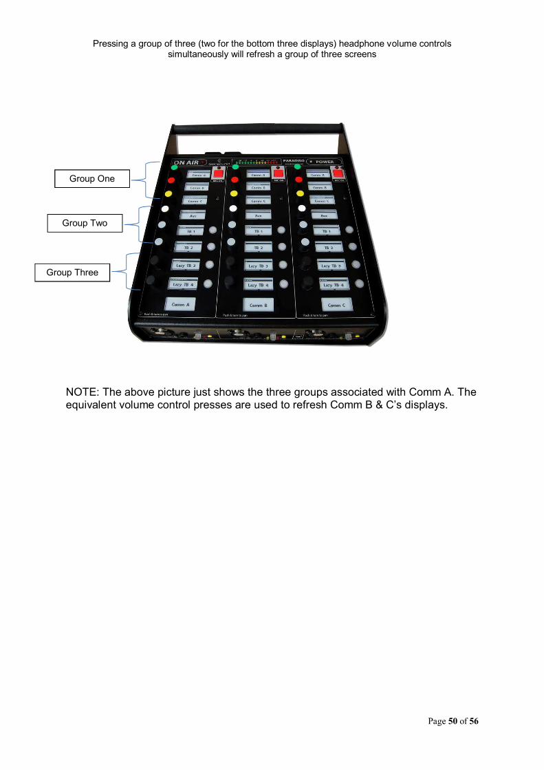
Pressing a group of three (two for the bottom three displays) headphone volume controls simultaneously will refresh a group of three screens
NOTE: The above picture just shows the three groups associated with Comm A. The equivalent volume control presses are used to refresh Comm B & C’s displays.
Group One
Group Two
Group Three

Page 51 of 56
AES67 MODE The Paradiso uses a module from Audinate called a Brooklyn Module for its network audio interface. Audinate are the company behind DanteTM and as such the module’s primary network audio protocol is Dante, however Audinate have enabled their module to comply with AES67 and therefore the Paradiso can be set to AES67 mode for interaction with other AES67 devices. Please note however that Glensound are relying on Audinate’s AES67 interface and are unfortunately not able to provide full AES67 support for the unit. AES67 support should be sought directly from Audinate.
1. Turning On AES67 Mode
If you want to use your Paradiso on an AES67 network and it has not been set to AES67 mode then this can be set in Dante controller by double clicking the Paradiso to open the Device View window where you will find an AES67 tab to enable AES67 support.
Once the AES67 drop down box has been enabled you’ll have to reboot the Paradiso for the change to take effect. After the reboot go back to the AES67 tab and set the multicast prefix address to one that is suitable for your newtork.
Page 52 of 56
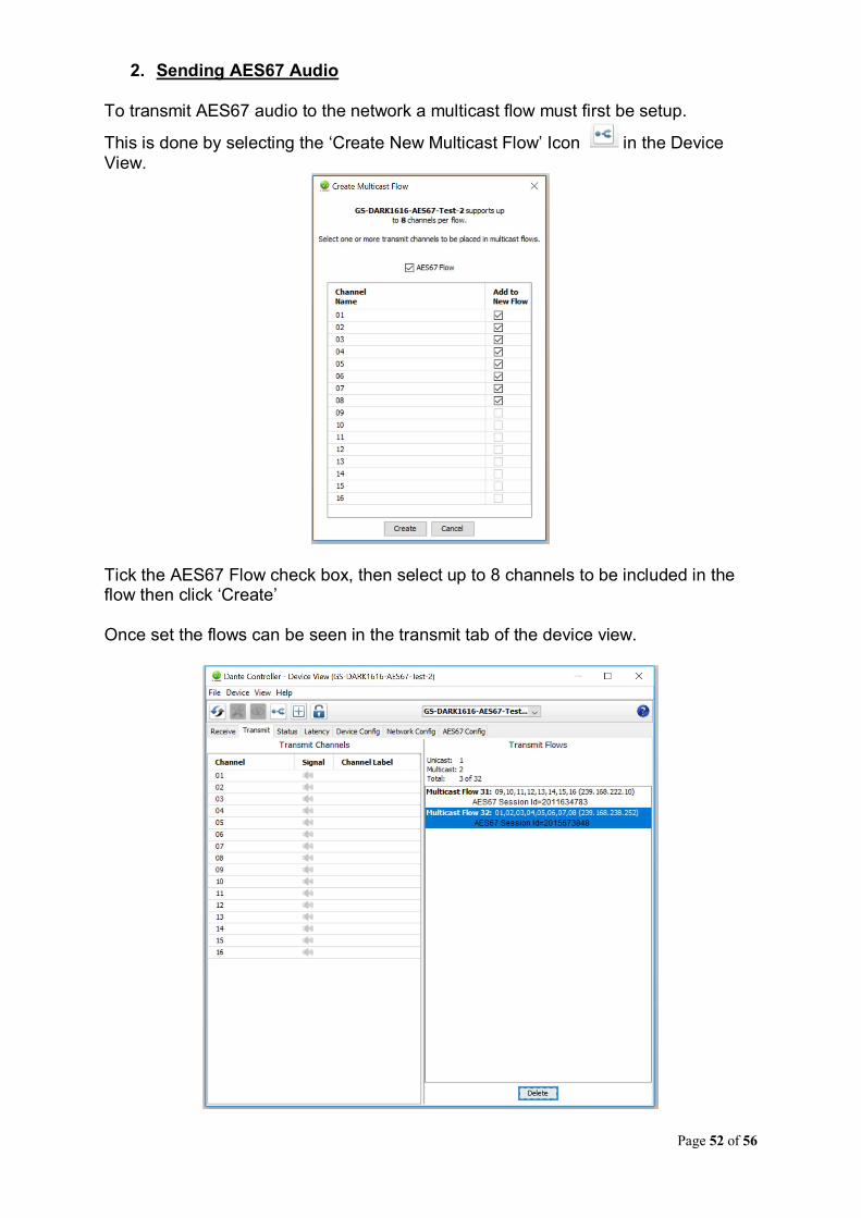
2. Sending AES67 Audio
To transmit AES67 audio to the network a multicast flow must first be setup.
This is done by selecting the ‘Create New Multicast Flow’ Icon in the Device View.
Tick the AES67 Flow check box, then select up to 8 channels to be included in the flow then click ‘Create’ Once set the flows can be seen in the transmit tab of the device view.
Page 53 of 56
3. Receiving AES67 Audio
Once a compatible AES67 stream is detected on the network by Dante Controller the AES67 flows will appear in the Dante Transmitters section in the Routing tab.
4. AES67 Restrictions
AES67 flows can only be generated with the following constraints:
Multicast Only
Non-redundant
Destination address in range 239.nnn.0.0 to 239.nnn.255.255 (239.nnn/16), port 5004
48kHz sampling rate
24 bit linear (L24) encoding
1 msec packet time
Up to 8 channels per stream Received AES67 flows have the following constraints:
Multicast Only
Non-redundant
Destination address in range 239.nnn.0.0 to 239.nnn.255.255 (239.nnn/16), port 5004. Must match destinatio address range.
48kHz sampling rate
L16 or L24 encoding
125usec, 250usec, 333usec, 1 msec packet time
Up to 8 channels per stream
Page 54 of 56
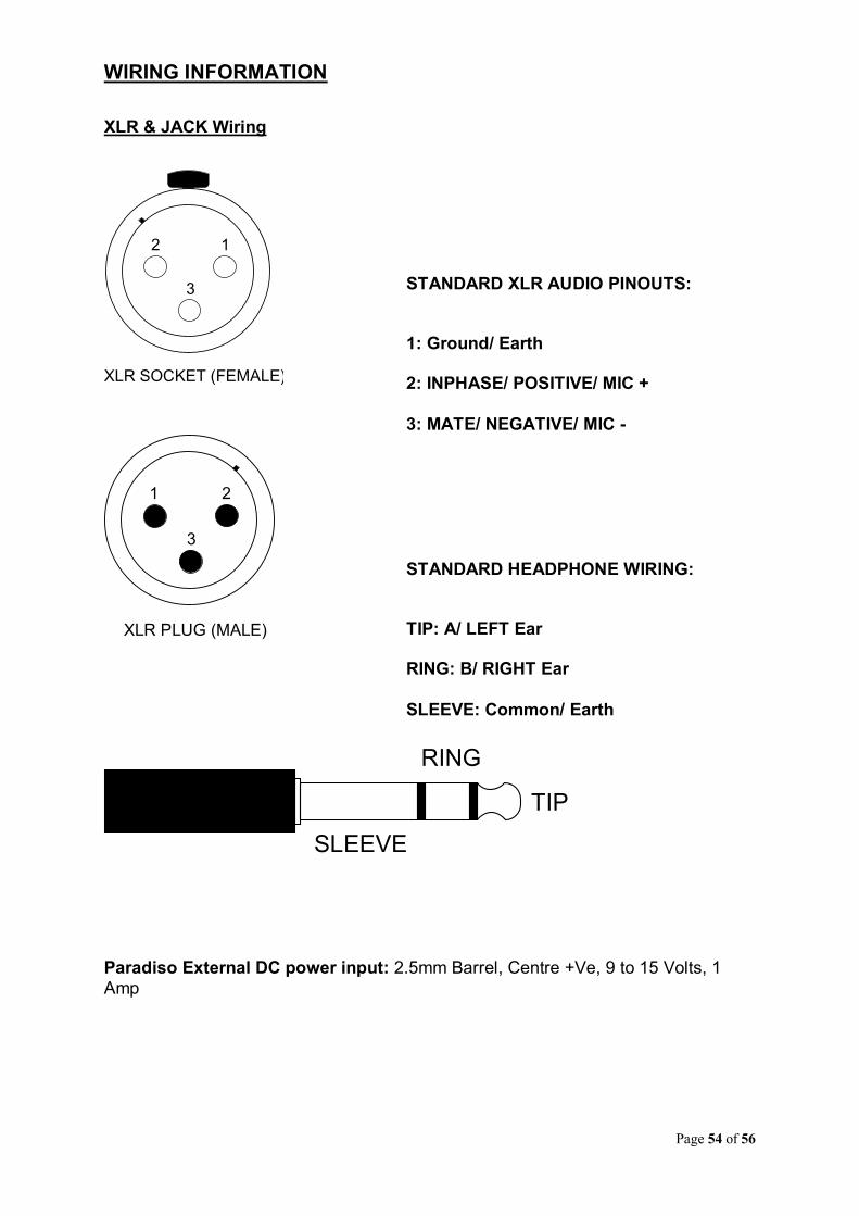
WIRING INFORMATION
XLR & JACK Wiring
Paradiso External DC power input: 2.5mm Barrel, Centre +Ve, 9 to 15 Volts, 1
Amp
12
3
XLR SOCKET (FEMALE)
1 2
3
XLR PLUG (MALE)
TIP
RING
SLEEVE
STANDARD XLR AUDIO PINOUTS: 1: Ground/ Earth 2: INPHASE/ POSITIVE/ MIC +
3: MATE/ NEGATIVE/ MIC -
STANDARD HEADPHONE WIRING: TIP: A/ LEFT Ear RING: B/ RIGHT Ear
SLEEVE: Common/ Earth

Page 55 of 56
D9 Wiring & Loop Interconnecting To External Equipment
DC Loop Out A DC Loop Out B DC Loop In A DC Loop In B AES3 IN Negative AES3 IN Positive Ground/ Earth AES3 OUT Positive AES3 OUT Negative
MICRO
GND
INSIDE PARADISO EXTERNAL EQUIPMENT
+V
GND
CONNECTING LOOP OUT TO A LOGIC INPUT
MICRO
GND
INSIDE PARADISO EXTERNAL EQUIPMENT
RELAY
PSU
+V
GND
CONNECTING LOOP OUT TO A RELAY
D C
on
ne
cto
rD
Co
nn
ecto
r
MICRO
MICRO
GND
INSIDE PARADISO EXTERNAL EQUIPMENT
+V
GND
CONNECTING LOOP OUT TO AN OPTO ISOLATOR
D C
on
ne
cto
r
MICRO
GND
INSIDE PARADISO EXTERNAL EQUIPMENT
+V
CONNECTING LOOP INPUT
D C
on
ne
cto
r
CONNECT LOOP IN
TO GROUND

Page 56 of 56
SPECIFICATIONS
FEATURES
POWER
AUDIO
PHYSICAL
External Mains PSU
Size
Power On LED
Shipping Weight
DC Input
Mechanics
AC Consumption
Weight
Shipping Carton Filtered IEC, 100 to 240VAC (+/-10%)47 - 63Hz
256 x 256 x 100mm (WxDxH)
Bright Blue
4.1Kg
2.5mm Barrel, Centre +Ve, 9 - 15 Volts
All aluminium construction, anodized andlaser etched, powder coated sides
<25 Watts
2.5Kg
Rugged export quality cardboard carton610 x 420 x 170mm (WxDxH)
Mic Input Gain Range
Mic Input Impedance
Headphone Impedance
Mic + Phantom Power Line Up
Equivalent Input Noise
Dynamic Mic Line Up
Line Input Impedance
Maximum Input Level Before Clipping
Line Input Line Up
Headphone Volume Pot Range
-40dB to +40dB
2k4
200 - 2000 Ohms
30dB
127dBu (22-22kHz RMS terminated 300 Ohms)
30dB
100k
Dynamic Mic: +10dBu Mic + 48V PH: +18dBuLine: +18dBu
0dBu (Gain range +/-20+dB)
+10dB to Off (+10dB to -30dB configuration option)
Headphone Impedance
Headphone THD + Noise (ref =8dBu)
Headphone Frequency Response
Maximum Headphone Output
Headphone Noise
16 to 1000 Ohms(Auto output level to match impedance)
0.008% @ 1kHz
>= -0.1dB 22Hz to 22kHz
+12dB into 600 Ohms
-76.6dB @ lineup (residual noise)
Frequency Response
Mic: > +/-0.25dB 50Hz to 22kHz (-2 @ 25Hz)Line: >= -0.1dB 22Hz to 22kHz
Dante/AES67 Network Interface
Sample Frequency: 48kHzResolution: 24 BitCan be configured for AES67
INCLUDED ITEMS
Handbook
Mains Cable
Physical A4 (download also available)
UK & EU Only, 2 metre mains plug to IEC
THD + Noise (Ref +8dBu)
100Hz = 0.023%1kHz = 0.012%10kHz = 0.014%
Rj45 Network Cable
2 metre Cat5 Rj45plug /Rj45plug cable
OPTIONAL ITEMS
Carrying Case
Fibre Modules
Long life Polypropylene Carrying Case
Multi Mode instead of Single Mode (No cost option)External Power Supply
Desktop style switch mode PSU


