Download - Outlook for PWA Experiments
Outlook for PWA Experiments
Ralph Assmann, Steffen Hillenbrand,Frank Zimmermann
CERN, BE Department, ABP Group
KET Meeting Dortmund 25 October 2010
themes
community interest and potential
first demonstration experiment for proton-driven plasma wakefield acceleration (PDPWA) at CERN
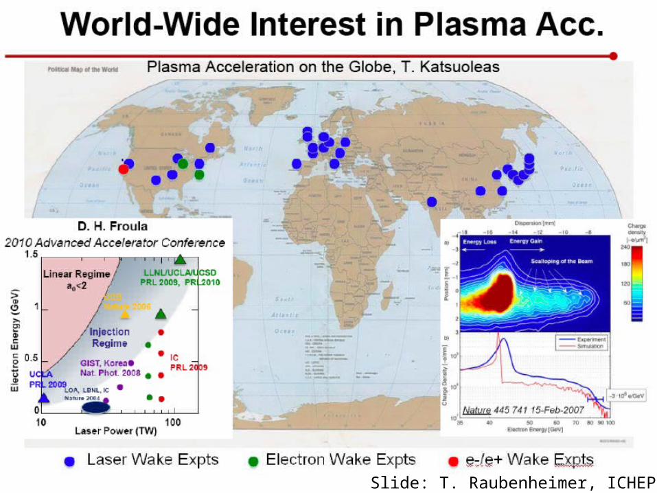
R. Assmann 3Slide: T. Raubenheimer, ICHEP

Gradient vs Plasma Wavelength
R. Assmann B. Hidding
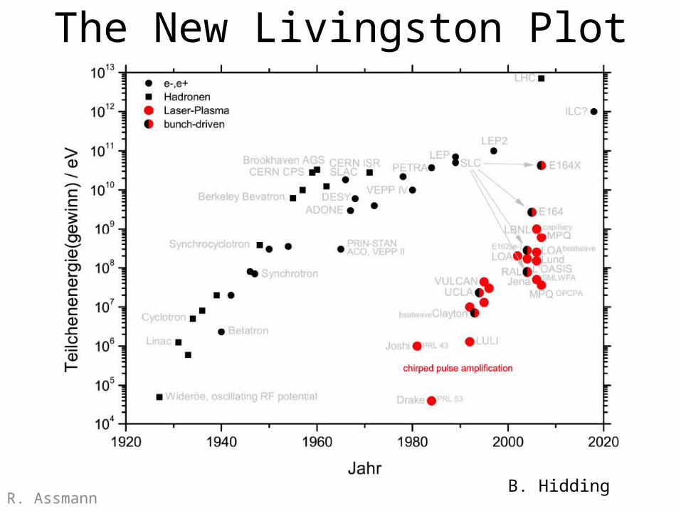
The New Livingston Plot
R. AssmannB. Hidding
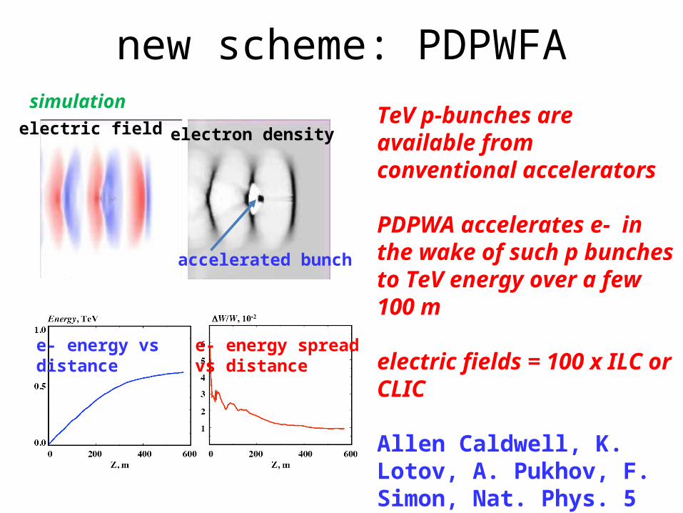
new scheme: PDPWFAsimulation
TeV p-bunches are available from conventional accelerators
PDPWA accelerates e- in the wake of such p bunches to TeV energy over a few 100 m
electric fields = 100 x ILC or CLIC
Allen Caldwell, K. Lotov, A. Pukhov, F. Simon, Nat. Phys. 5 (2009) 363.
electric field electron density
accelerated bunch
e- energy vs distance
e- energy spreadvs distance
ICFA & ICUIL interest“A joint task force between ICFA and the
International Committee on Ultra-High Intensity Lasers (ICUIL) has been set up to study the laser
acceleration of particles. A first workshop has already been held [in
Darmstadt], and a technical report will be written on such accelerators and the technical challenges that
still need to be overcome.”
Summary of 63rd ICFA meeting24 July 2010
(ICFA=International Committee for Future Accelerators)
EuCARD interest
“[New] associate network on laser and plasma acceleration in EuCARD-WP4 (R.Assmann et al)
…
ESGARD will monitor the outcome of the laser/plasma network … to include such R&D
field in EuCARD2.”
Jean-Pierre KoutchoukEuCARD Project Coordinator12 October 2010
(EuCARD = European Coordination for Accelerator Research and Development)
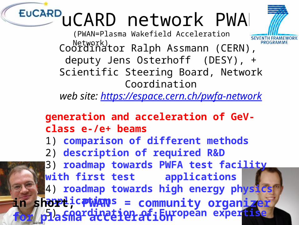
EuCARD network PWAN(PWAN=Plasma Wakefield Acceleration Network)
Coordinator Ralph Assmann (CERN), deputy Jens Osterhoff (DESY), +
Scientific Steering Board, Network Coordinationweb site: https://espace.cern.ch/pwfa-network
generation and acceleration of GeV-class e-/e+ beams1) comparison of different methods2) description of required R&D3) roadmap towards PWFA test facility with first test
applications4) roadmap towards high energy physics applications5) coordination of European expertise
in short, PWAN = community organizer for plasma acceleration
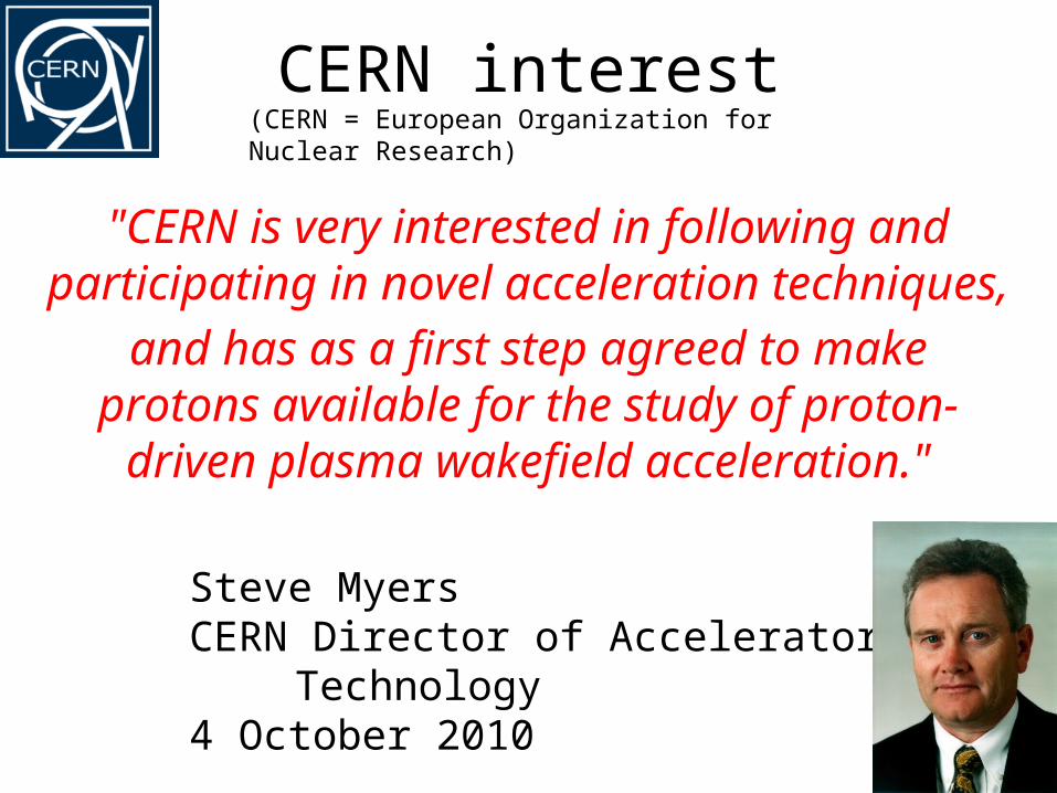
CERN interest
"CERN is very interested in following and participating in novel acceleration techniques,
and has as a first step agreed to make protons available for the study of proton-driven plasma wakefield acceleration."
Steve MyersCERN Director of Accelerators &
Technology4 October 2010
(CERN = European Organization for Nuclear Research)
11
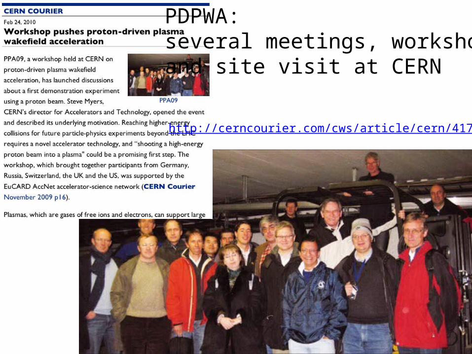
http://cerncourier.com/cws/article/cern/41714
PDPWA: several meetings, workshops,and site visit at CERN
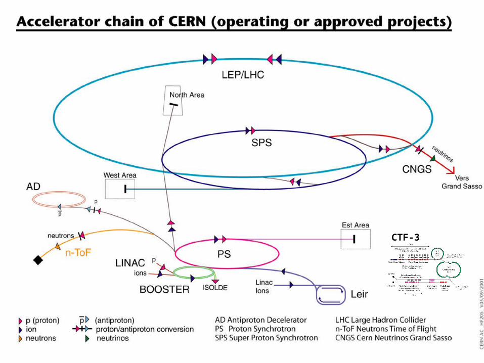
CTF-3
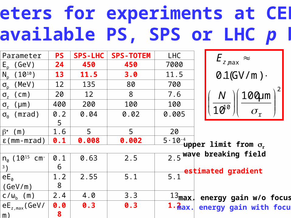
Parameter PS SPS-LHC SPS-TOTEM LHCEp (GeV) 24 450 450 7000Np (1010) 13 11.5 3.0 11.5σp (MeV) 12 135 80 700σz (cm) 20 12 8 7.6σr (μm) 400 200 100 100σθ (mrad) 0.25 0.04 0.02 0.005 (m) 1.6 5 5 20ε(mm-mrad) 0.1 0.008 0.002 5·10-4
n0 (1015 cm-3) 0.16 0.63 2.5 2.5eE0 (GeV/m) 1.28 2.55 5.1 5.1c/ωb (m) 2.4 4.0 3.3 13eEz,max(GeV/m) 0.08 0.3 0.3 1.2 0.05 0.12 0.06 0.24Ldephase (m) 11 330 240 4260W (GeV) 0.13 1.4 1.5 23Wdephase (GeV) 0.9 100 74 5100
parameters for experiments at CERN with available PS, SPS or LHC p beams
upper limit from r
wave breaking field
estimated gradient
max. energy gain w/o focusingmax. energy gain with focusing
2
r10
max,
μm100
10
)GV/m(1.0
N
Ez

CTF-3
PS East Area, ~30-60 m, 24 GeVSPS West Area, ~600 m, 300-450 GeV
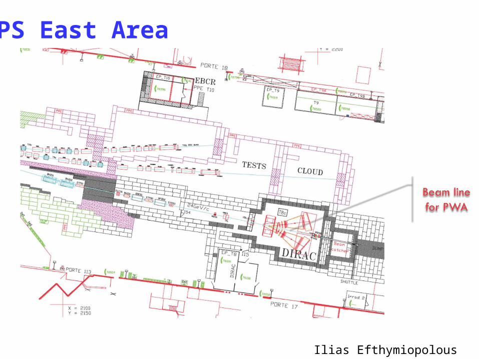
PS East Area
Ilias Efthymiopolous
PS beam line (DIRAC) semi-fast extraction from PS machine
issues to clarify:• removal of the DIRAC experiment – when?• even after DIRAC removal there is a strong interest to `reuse the area for electronics irradiation facility• total length for experimental area ~30m, difficult to
prolong it – beam dump ~6m• a proposal is under study to renovate the East Hall Exp.
Area• time scale: earliest in 2012, or during the long shutdown in 2013/2014
Ilias Efthymiopolous
Christoph Hessler, TE/ABT, CERN
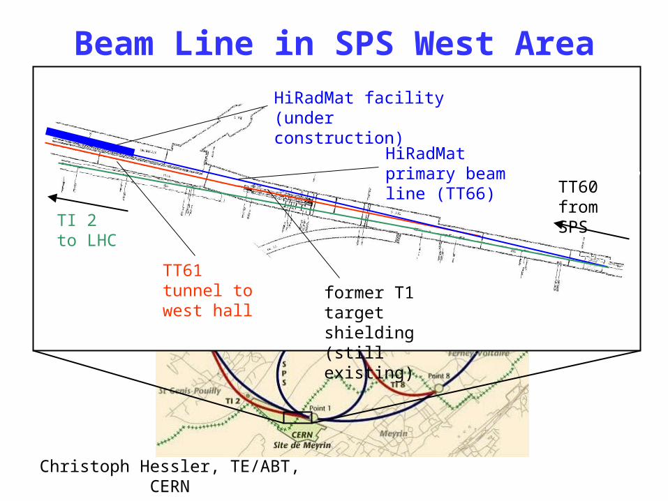
Beam Line in SPS West Area
TT60 from SPS
TI 2to LHC
HiRadMat facility(under construction)
TT61 tunnel to west hall former T1
target shielding (still existing)
HiRadMat primary beam line (TT66)
SPS West Area
Ilias Efthymiopolous
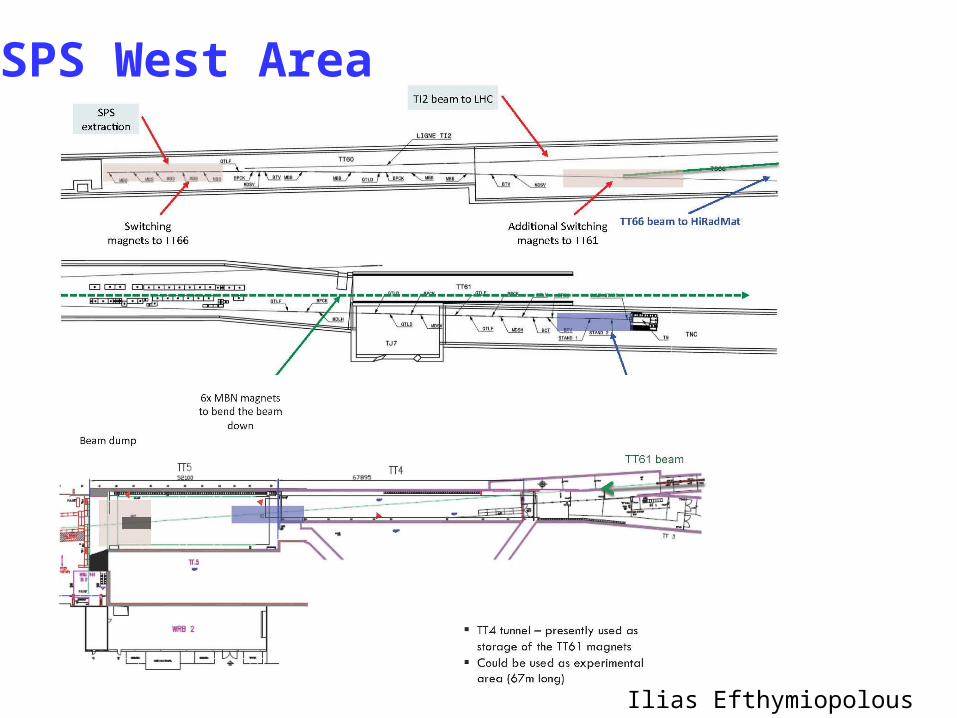
SPS beam line (TT61, TT4)
• status of the available infrastructure, i.e. ventilation, services, electricity, etc.
• highly radioactive T1 target shielding needs to be removed
• large slope of 8.5% • the line is long: availability of magnets and power supplies?• except for the switching magnets, the rest should be
available from old installations, BUT…• former H3 beam line designed for 250 GeV/c
→ are TT61 tunnel geometry & old magnets suitable for 450 GeV beams? or can we have 250 GeV beams in this line?
Ilias Efthymiopolous, Christoph Hessler
Christoph Hessler, TE/ABT, CERN 20
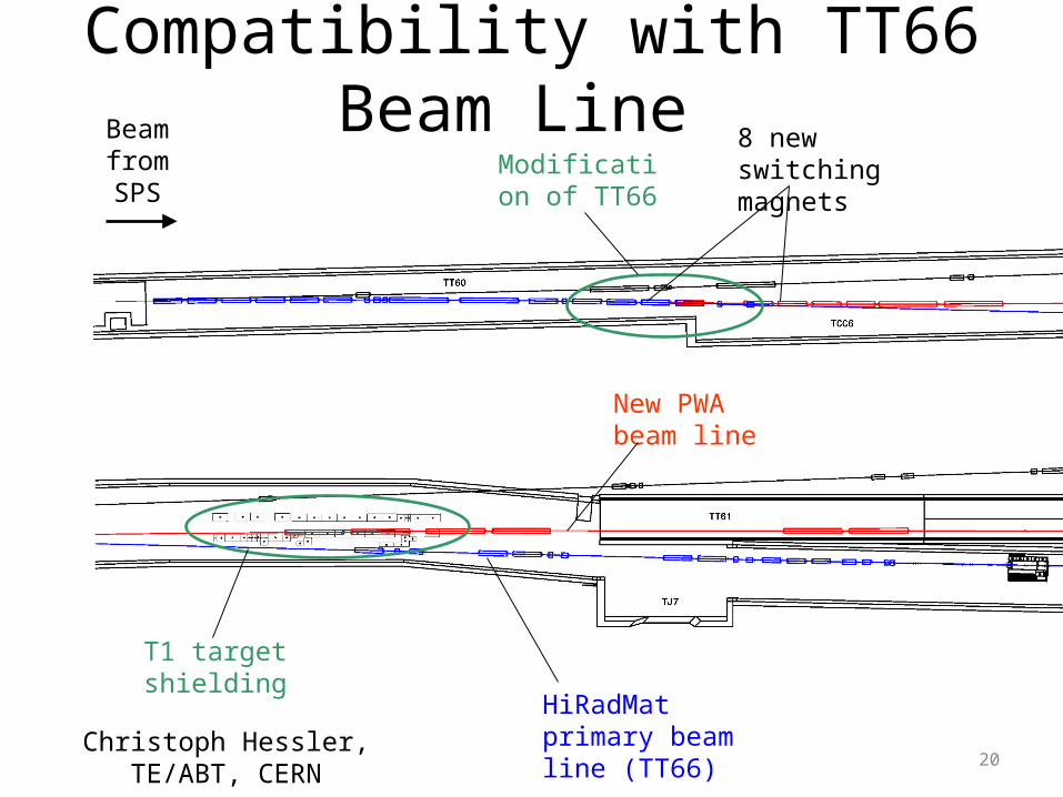
Compatibility with TT66 Beam Line Beam from SPS
HiRadMat primary beam line (TT66)
New PWA beam line
Modification of TT66
8 new switching magnets
T1 target shielding
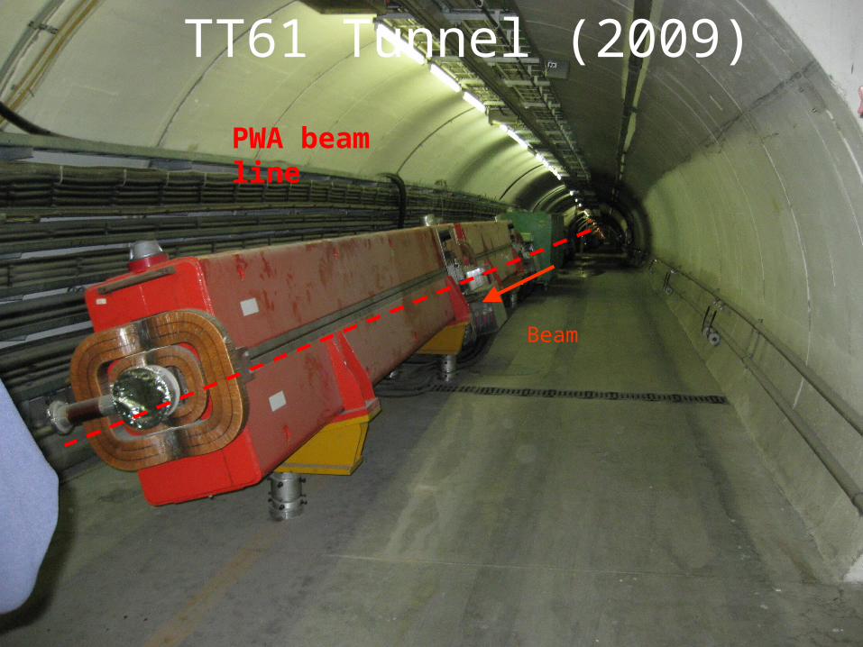
TT61 Tunnel (2009)
Beam
PWA beam line
Christoph Hessler, TE/ABT, CERN
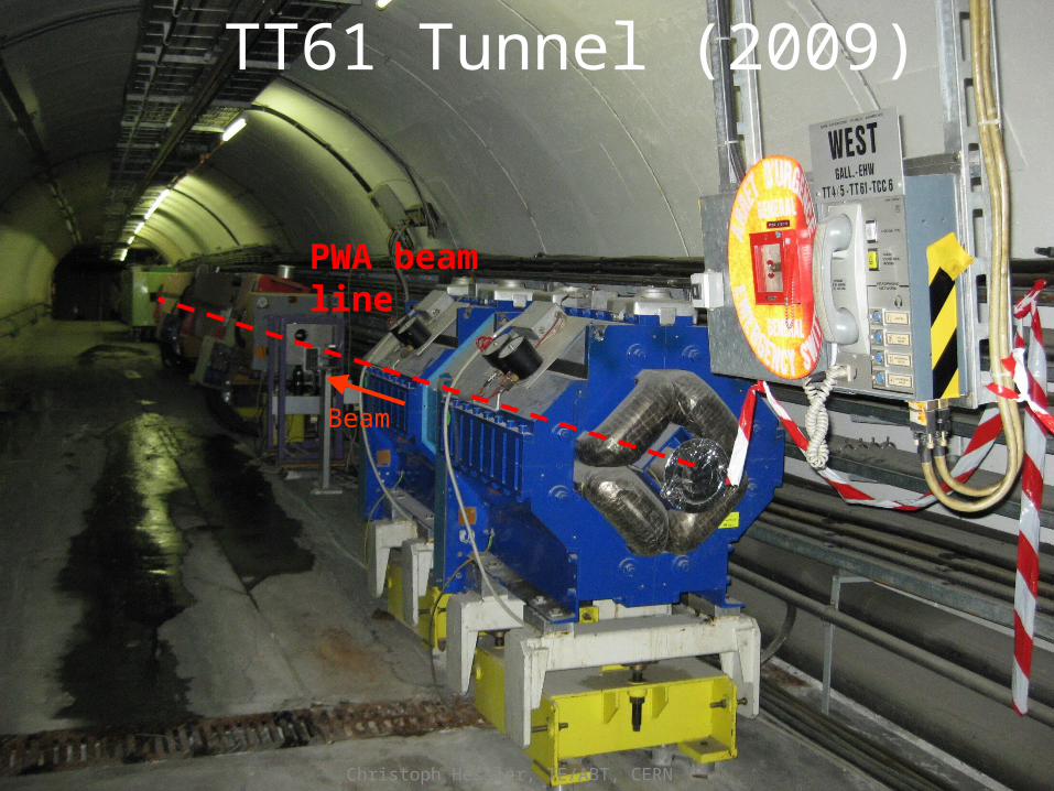
TT61 Tunnel (2009)
Beam
PWA beam line
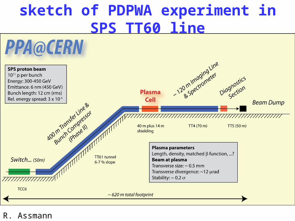
sketch of PDPWA experiment in SPS TT60 line
R. Assmann
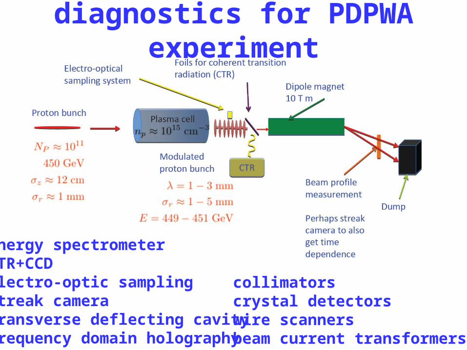
diagnostics for PDPWA experiment
energy spectrometerOTR+CCDelectro-optic samplingstreak cameratransverse deflecting cavityfrequency domain holography
collimatorscrystal detectorswire scannersbeam current transformers
C. Joshi
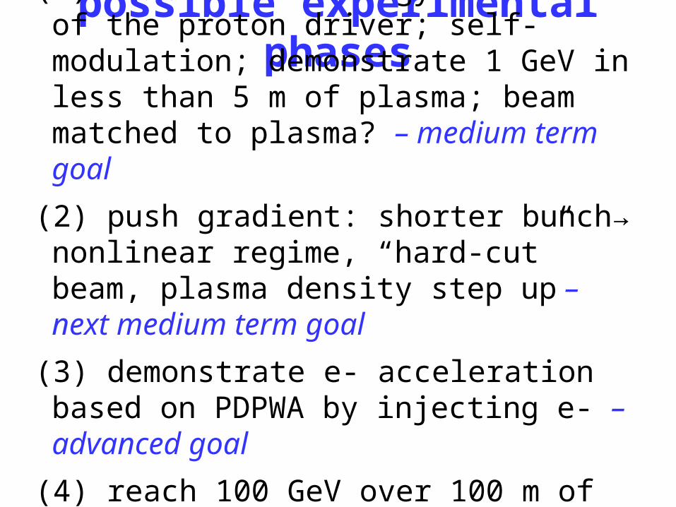
possible experimental phases(1) observe the energy variation of the proton
driver; self-modulation; demonstrate 1 GeV in less than 5 m of plasma; beam matched to plasma? – medium term goal
(2) push gradient: shorter bunch→ nonlinear regime, “hard-cut” beam, plasma density step up – next medium term goal
(3) demonstrate e- acceleration based on PDPWA by injecting e- – advanced goal
(4) reach 100 GeV over 100 m of plasma; produce TeV-scale e- beams – ultimate goal
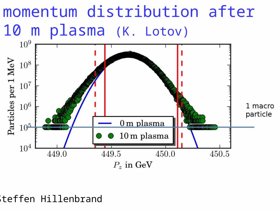
momentum distribution after 10 m plasma (K. Lotov)
Steffen Hillenbrand
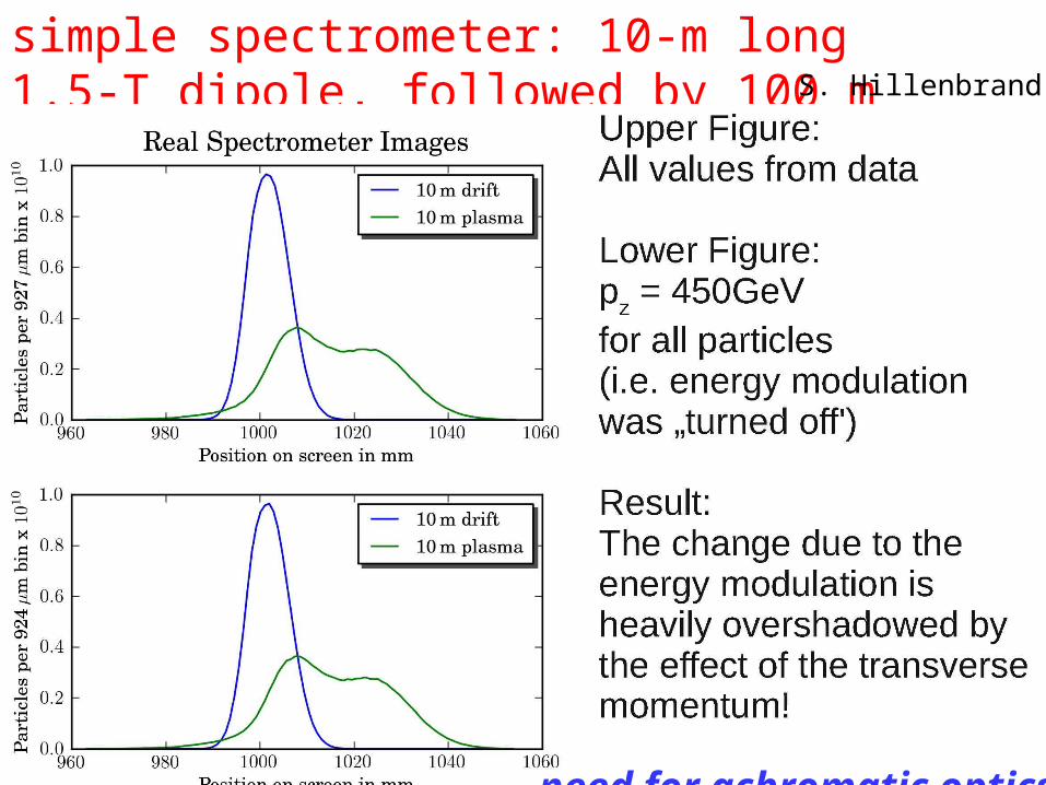
simple spectrometer: 10-m long 1.5-T dipole, followed by 100 m drift and screen S. Hillenbrand
need for achromatic optics!
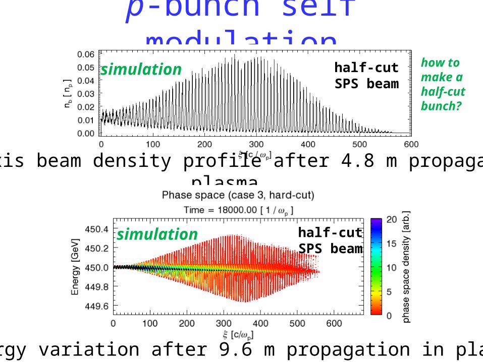
p-bunch self modulation
on-axis beam density profile after 4.8 m propagation in plasma
energy variation after 9.6 m propagation in plasma
half-cutSPS beam
half-cutSPS beam
simulation
simulation
how tomake a half-cutbunch?
450 500400350300 550Energy, G eV
Num
ber
of p
artic
les,
arb
. uni
ts
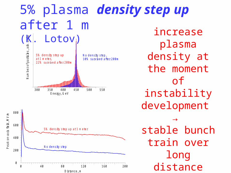
N o density step,10% survived after 200m
5% density step upat 1 m eter,22% survived after 200m
5% density step up at 1 m eter
N o density step
0 40 80 120 160 2000
800
600
400
200
D istance, m
Pea
k on
-axi
s fie
ld, M
V/m
increase plasma density at the moment
of instability development
→ stable bunch
train over long distance
5% plasma density step up after 1 m (K. Lotov)
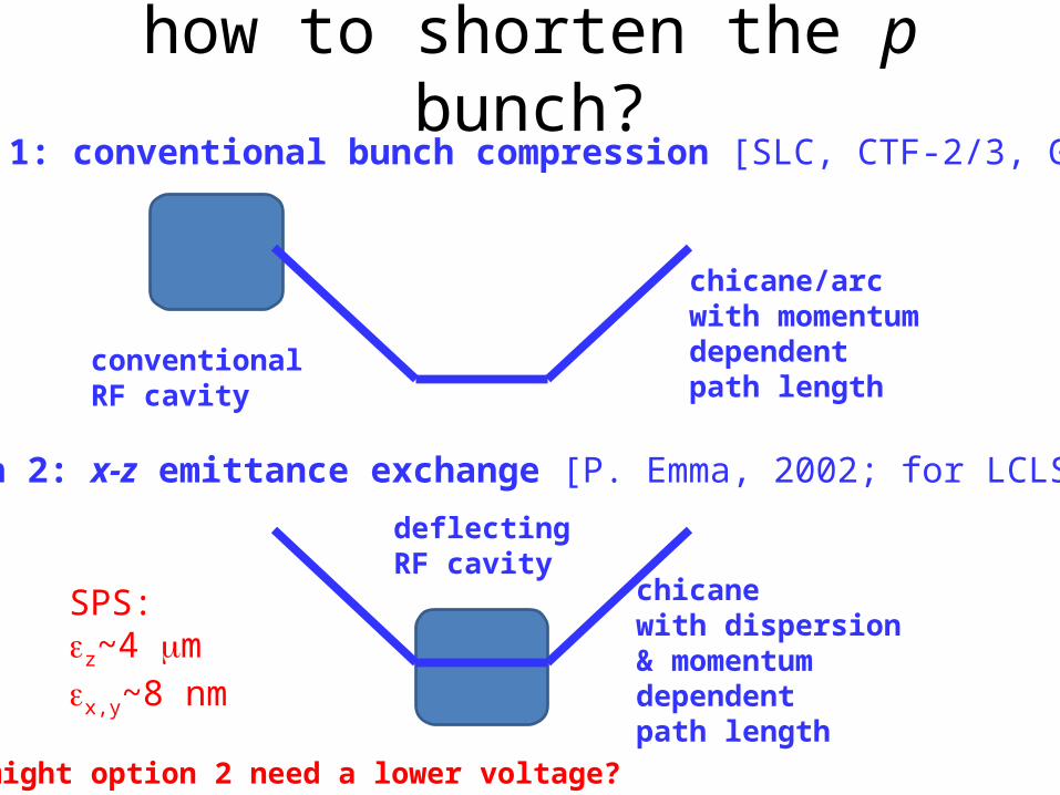
how to shorten the p bunch?
conventionalRF cavity
chicane/arcwith momentumdependentpath length
option 1: conventional bunch compression [SLC, CTF-2/3, G. Xia]
deflecting RF cavity
chicanewith dispersion& momentumdependentpath length
option 2: x-z emittance exchange [P. Emma, 2002; for LCLS]
might option 2 need a lower voltage?
SPS:z~4 mx,y~8 nm
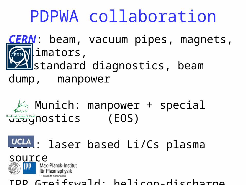
PDPWA collaborationCERN: beam, vacuum pipes, magnets, collimators,
standard diagnostics, beam dump, manpower
MPP Munich: manpower + special diagnostics (EOS)
UCLA: laser based Li/Cs plasma source
IPP Greifswald: helicon-discharge based Ar plasma source
Letter of Intent in preparation,to be submitted to CERN SPSC
(G. Xia et al)

thank you for your attention!


