Osprey Corporation
Installation and Maintenance Manual
Osprey Final Filter
1
TABLE OF CONTENTS
INTRODUCTION………………………………………………………………………………...2
INSTALLATION ............................................................................................................................3
Setup ..........................................................................................................................................3
Enclosure Assembly for Stand Alone Final Filters....................................................................6
Door Installation ..................................................................................................................6
Enclosure Anchoring ...........................................................................................................7
Ducting a Stand Alone Final Filter ......................................................................................7
Filter Cartridge Installation........................................................................................................8
Cartridge Support Installation………………………………………………………...……9
Compressed Air Supply ...........................................................................................................10
Electrical Connections .............................................................................................................10
The Wiring Process............................................................................................................10
Choosing the Correct Wiring Procedure............................................................................11
Wiring from the Timer Board to the Solenoid...................................................................11
Photohelic Connections .....................................................................................................11
Initial Checks ...........................................................................................................................12
OPERATION.................................................................................................................................13
Electrical Settings ....................................................................................................................13
Solenoid Sequence Setup...................................................................................................13
Selector and Push Button Switch Operation......................................................................13
Startup ......................................................................................................................................13
MAINTENANCE ..........................................................................................................................15
Periodic Maintenance Schedule...............................................................................................15
Filter Cartridge Replacement...................................................................................................15
SPARE PARTS LISTING .............................................................................................................17

2
INTRODUCTION
The Osprey Final Filter is designed to enhance the filtering capacity of the Osprey Drum Filter or
PhoenixTM
Filter System. The purpose is to filter fine particulate material from an air stream.
The filter cartridges remove 99.95% of particulate matter down to 1 micron. Clean air can be
exhausted into manufacturing plant, atmosphere, or temperature control system.
The Final Filter uses a long lasting, fiber resistant cartridge design. This allows easy installation,
low maintenance, and automatic pulsejet cleaning.
This manual was written for the Osprey Final Filter and is applicable to all sizes of the Osprey
Final Filter. Drawings in this manual apply to the base model unless otherwise noted.
This manual is divided into five sections:
1) Introduction
2) Installation and Start-up
3) Operation
4) Maintenance
5) Spare Parts Listing
Safety information and information of special note are included throughout the manual. Four
different types of notes are used in this manual and appear as shown.
-WARNING- is used to prevent personnel injury.is used to prevent personnel injury.is used to prevent personnel injury.is used to prevent personnel injury.
-CAUTION- is used to prevent machine damage.is used to prevent machine damage.is used to prevent machine damage.is used to prevent machine damage.
-IMPORTANT- is used to show inforis used to show inforis used to show inforis used to show information that is necessary to insure proper installation mation that is necessary to insure proper installation mation that is necessary to insure proper installation mation that is necessary to insure proper installation and operation.and operation.and operation.and operation.
-NOTE- is used to provide information of special interest.is used to provide information of special interest.is used to provide information of special interest.is used to provide information of special interest.
3
INSTALLATION
Setup
First, check the crates shipped against the shipping list to identify missing or damaged parts.
Follow the instructions in the bulletin titled “What to do if your shipment is damaged, lost, or
stolen!” located in the Osprey job manual shipped with the equipment, if applicable. If all is
well, uncrate the Final Filter and gather the parts near, but not on, the planned erection site.
Before beginning installation, go over the assembly drawings (included in the Osprey job manual
shipped with the equipment) to become familiar with the components that will require assembly.
Also, read the Drum Filter (or PhoenixTM
Filter) Installation and Operation Manual completely.
Install the drum filter and begin installation of the enclosure before installing the Final Filter.
Assembly of the Final Filter section is best done while installing the drum filter enclosure. Use
Figure 1 and the assembly drawings specific to your equipment (included in the Osprey job
manual) as a guide throughout this installation. If you have purchased a stand alone Final Filter,
assemble the filter enclosure following the section labeled “Enclosure Assembly for Stand Alone
Final Filters”.
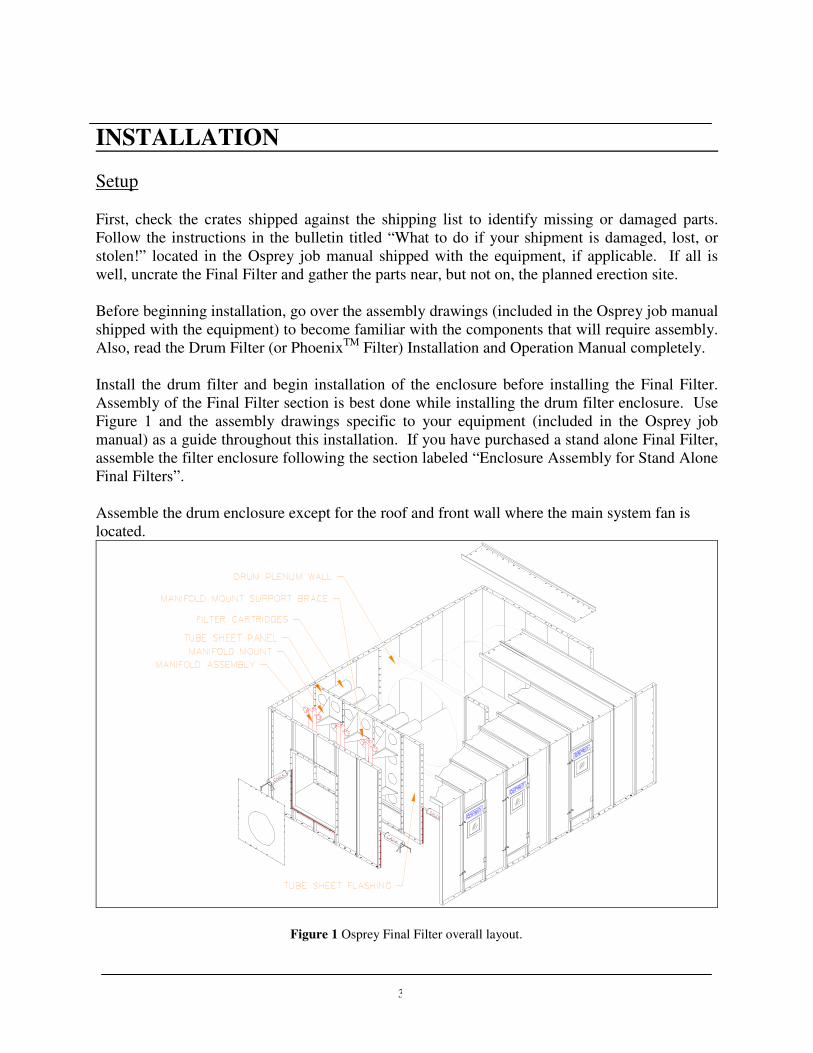
Assemble the drum enclosure except for the roof and front wall where the main system fan is
located.
Figure 1 Osprey Final Filter overall layout.
4
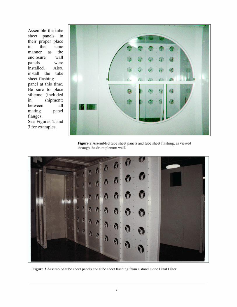
Assemble the tube
sheet panels in
their proper place
in the same
manner as the
enclosure wall
panels were
installed. Also,
install the tube
sheet-flashing
panel at this time.
Be sure to place
silicone (included
in shipment)
between all
mating panel
flanges.
See Figures 2 and
3 for examples.
Figure 2 Assembled tube sheet panels and tube sheet flashing, as viewed
through the drum plenum wall.
Figure 3 Assembled tube sheet panels and tube sheet flashing from a stand alone Final Filter.

Figure 4 Manifolds installed on manifold mounts.
5
Bolt on the enclosure roof panels at this time. This will steady the tube sheet panels for the rest
of the installation.
Bolt the manifold mounts into their proper position, aligning the holes on its flange with the row
of holes down the center of the tube sheet panels. Use 3/8"-16 wiz bolts and nuts to bolt it.
Locate the manifold mount braces and bolt them to the tube sheet panels and to the manifold
mounts using 3/8"-16 wiz bolts and nuts.
Now, find the air manifolds. The air manifolds come preassembled with the diaphragm valves,
solenoid valves, and air hoses. Secure them to the manifold mount braces installed earlier using
3/8"-16 x 1 1/4" bolts, 3/8" washers and lock washers, and 3/8"-16 nuts.
When the manifolds are installed, install the manifold stiffeners. These keep movement and
vibration of the manifolds to a minimum when the diaphragm valves are activated and the filter
cartridges are pulse cleaned.
-NOTE- Hardware may differ for some Hardware may differ for some Hardware may differ for some Hardware may differ for some assemblies. Check the assembly assemblies. Check the assembly assemblies. Check the assembly assemblies. Check the assembly drawings shipped with the drawings shipped with the drawings shipped with the drawings shipped with the equipment for proper mounting equipment for proper mounting equipment for proper mounting equipment for proper mounting hardware.hardware.hardware.hardware.
-WARNING- Do not damage Do not damage Do not damage Do not damage the air hoses the air hoses the air hoses the air hoses when installing when installing when installing when installing the manifolds the manifolds the manifolds the manifolds and manifold and manifold and manifold and manifold stiffeners.stiffeners.stiffeners.stiffeners.
Figure 4 shows an installation of the tube
sheet panels, manifold mounts and brackets,
the manifolds, and the manifold stiffeners.
-NOTE- ActActActActual assemblies mayual assemblies mayual assemblies mayual assemblies may differ from figures differ from figures differ from figures differ from figures used in this manual. used in this manual. used in this manual. used in this manual. Consult the assembly Consult the assembly Consult the assembly Consult the assembly drawings shipped with drawings shipped with drawings shipped with drawings shipped with the equipment for the equipment for the equipment for the equipment for details.details.details.details.
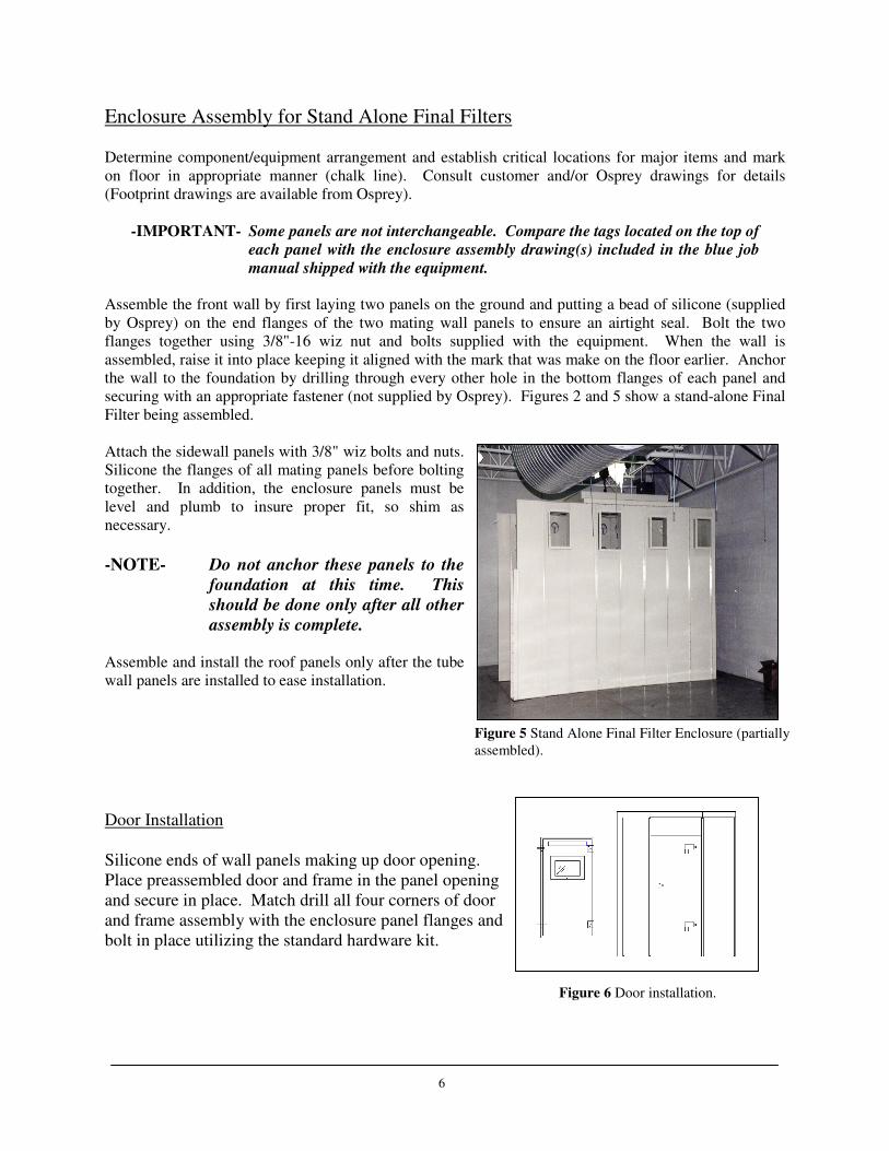
Figure 5 Stand Alone Final Filter Enclosure (partially
assembled).
Enclosure Assembly for Stand Alone Final Filters Determine component/equipment arrangement and establish critical locations for major items and mark
on floor in appropriate manner (chalk line). Consult customer and/or Osprey drawings for details
(Footprint drawings are available from Osprey).
-IMPORTANT- Some panels are not interchangeable. Compare the tags located on the top of
each panel with the enclosure assembly drawing(s) included in the blue job
manual shipped with the equipment.
Assemble the front wall by first laying two panels on the ground and putting a bead of silicone (supplied
by Osprey) on the end flanges of the two mating wall panels to ensure an airtight seal. Bolt the two
flanges together using 3/8"-16 wiz nut and bolts supplied with the equipment. When the wall is
assembled, raise it into place keeping it aligned with the mark that was make on the floor earlier. Anchor
the wall to the foundation by drilling through every other hole in the bottom flanges of each panel and
securing with an appropriate fastener (not supplied by Osprey). Figures 2 and 5 show a stand-alone Final
Filter being assembled.
Attach the sidewall panels with 3/8" wiz bolts and nuts.
Silicone the flanges of all mating panels before bolting
together. In addition, the enclosure panels must be
level and plumb to insure proper fit, so shim as
necessary.
-NOTE- Do not anchor these panels to the
foundation at this time. This
should be done only after all other
assembly is complete. Assemble and install the roof panels only after the tube
wall panels are installed to ease installation.
Door Installation
Silicone ends of wall panels making up door opening.
Place preassembled door and frame in the panel opening
and secure in place. Match drill all four corners of door
and frame assembly with the enclosure panel flanges and
bolt in place utilizing the standard hardware kit.
Figure 6 Door installation.
6
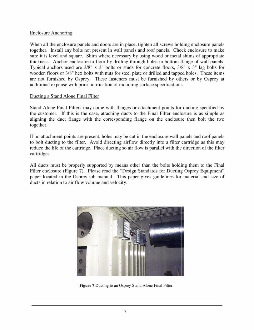
Figure 7 Ducting to an Osprey Stand Alone Final Filter.
7
Enclosure Anchoring
When all the enclosure panels and doors are in place, tighten all screws holding enclosure panels
together. Install any bolts not present in wall panels and roof panels. Check enclosure to make
sure it is level and square. Shim where necessary by using wood or metal shims of appropriate
thickness. Anchor enclosure to floor by drilling through holes in bottom flange of wall panels.
Typical anchors used are 3/8" x 3" bolts or studs for concrete floors, 3/8" x 3" lag bolts for
wooden floors or 3/8" hex bolts with nuts for steel plate or drilled and tapped holes. These items
are not furnished by Osprey. These fasteners must be furnished by others or by Osprey at
additional expense with prior notification of mounting surface specifications.
Ducting a Stand Alone Final Filter
Stand Alone Final Filters may come with flanges or attachment points for ducting specified by
the customer. If this is the case, attaching ducts to the Final Filter enclosure is as simple as
aligning the duct flange with the corresponding flange on the enclosure then bolt the two
together.
If no attachment points are present, holes may be cut in the enclosure wall panels and roof panels
to bolt ducting to the filter. Avoid directing airflow directly into a filter cartridge as this may
reduce the life of the cartridge. Place ducting so air flow is parallel with the direction of the filter
cartridges.
All ducts must be properly supported by means other than the bolts holding them to the Final
Filter enclosure (Figure 7). Please read the “Design Standards for Ducting Osprey Equipment”
paper located in the Osprey job manual. This paper gives guidelines for material and size of
ducts in relation to air flow volume and velocity.
8
Filter Cartridge Installation
The number of filter cartridges included with each Osprey Final Filter is determined by the volume of air
passing through the filter and the speed of the airflow. There may be just a single cartridge for each
opening in the tube sheet panels, or two cartridges may be installed end to end to provide desirable air
flow characteristics.
In each case, install the cartridges starting at the top of the tube sheet panel. Work across and
then down to provide best access.
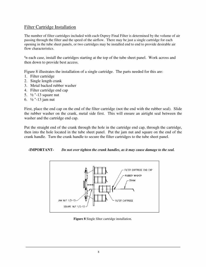
Figure 8 illustrates the installation of a single cartridge. The parts needed for this are:
1. Filter cartridge
2. Single length crank
3. Metal backed rubber washer
4. Filter cartridge end cap
5. ½ "-13 square nut
6. ½ "-13 jam nut
First, place the end cap on the end of the filter cartridge (not the end with the rubber seal). Slide
the rubber washer on the crank, metal side first. This will ensure an airtight seal between the
washer and the cartridge end cap.
Put the straight end of the crank through the hole in the cartridge end cap, through the cartridge,
then into the hole located in the tube sheet panel. Put the jam nut and square on the end of the
crank handle. Turn the crank handle to secure the filter cartridges to the tube sheet panel.
-IMPORTANT- Do not over tighten the crank handles, as it may cause damage to the seal.
Figure 8 Single filter cartridge installation.

9
Double cartridge installation is similar to the single cartridge installation. The only differences
are that there are two cartridges on a longer crank, with a spider in between the cartridges for
support. Figure 9 illustrates this.
Cartridge Support Installation
Some Osprey Final Filters come with a support structure for the filter cartridges. Installation of
this support assembly is straightforward. Bolt the cross arms to the vertical support, and place
this behind the filter cartridges so that the cranks holding the cartridges in place rest in the slots
in the cross arm. When in place, drill holes through the bottom feet of the vertical supports into
the foundation. Anchor into place with fasteners suitable for the foundation material. Drill holes
through the top feet into the roof panels and bolt in place. Figure 10 below shows a double
cartridge final filter with a cartridge support assembly.
Figure 9 Double filter cartridge installation.
Figure 10 Double cartridges with cartridge support assembly.

10
Compressed Air Supply
-CAUTION- Purge air lines to remove debris before connecting to air manifold. Purge air lines to remove debris before connecting to air manifold. Purge air lines to remove debris before connecting to air manifold. Purge air lines to remove debris before connecting to air manifold.
Remove the plastic pipe cap from the end of the air manifold and connect the air supply line.
Osprey recommends an air supply pressure between 80psi and 100psi, with 90psi the optimum
pressure. 2.1scfm is required for systems with ¾” [20mm] diaphragm valves and 3.4scfm is
required for systems with 1” [25mm] diaphragm valves. 1" NPT connections for air supply lines
are located at each end of the air manifold(s). Use Teflon tape on all threaded air connections.
Osprey recommends additional
components installed on the compressed
air supply to the final filter manifolds.
These components are not supplied by
Osprey as part of the base model.
A lock out shut-off air valve (bleed
type), bleed type regulator and gauge,
filter, and automatic condensate valve
should be installed to the air supply line.
These components should preferably be
located in the building for convenient
service and startup/shutdown of the unit.
Figure 11 illustrates an example arrangement
of these components.
-NOTE- It is important It is important It is important It is important that the air supply be oil and moisture free. Contamination in the that the air supply be oil and moisture free. Contamination in the that the air supply be oil and moisture free. Contamination in the that the air supply be oil and moisture free. Contamination in the air used to clean filter elements will result in poor cleaning and loss in air used to clean filter elements will result in poor cleaning and loss in air used to clean filter elements will result in poor cleaning and loss in air used to clean filter elements will result in poor cleaning and loss in performance.performance.performance.performance.
Electrical Connections
-NOTE- All electrical work must be done byAll electrical work must be done byAll electrical work must be done byAll electrical work must be done by a qualified electrician and according to local a qualified electrician and according to local a qualified electrician and according to local a qualified electrician and according to local codes.codes.codes.codes.
Electrical control panels are built by Osprey at world voltages. All electrical schematics and
panel layouts are enclosed in the panel at time of shipping. Another copy is included in the
Osprey Job Manual sent with the equipment.
Determine the power requirements of the Final Filter.
The Wiring Process
For Final Filters, the wiring process begins with the Control Panel. The Control Panel should be
situated as close as possible to the filters in order for controls and wiring to be highly accessible.
Figure 11 Compressed air supply components.
11
Choosing the Correct Wiring Procedure
The wiring procedure between the Control Panel and the Final Filter manifolds may be
accomplished in various ways. Osprey suggests a single EMT or Sealtight from the Control
Panel to each manifold bank. This depends on the size of the Final Filter and implies that
anywhere from two (2) to seven (7) runs between the Final Filter and the Control Panel would be
needed.
A second suggestion would be to run a sufficiently larger EMT from the Control Panel to a
junction box located within the Final Filter. (From the junction box, single runs of Sealtight can
be wired to each Solenoid junction box as needed.)
Wiring from the Timer Board to the Solenoid
Notice as the wiring from the solenoids to the timer boards is being done, that there will be
occasions where two (2) solenoids are wired on one (1) output terminal, which is located on the
timer boards. This doubling up of solenoids on the timer board outputs may be randomly wired
through the terminals. Doubling up is executed to guarantee that each solenoid is wired back to
the timer boards. When wiring two solenoids from one output terminal on the timer boards,
observe that the solenoids are located on different manifolds. This is to insure proper function of
the air valve and air pressure. The cleaning process entails sequential operation of each
individual manifold firing independently. When initial wiring takes place, consider the order of
the cleaning procedure: The system begins at the top of the manifold, travels across, and
downward to the next manifold. The beginning of the following cleaning series originates at the
first manifold once again. This method always progresses from top to bottom, repeatedly.
Photohelic Connections
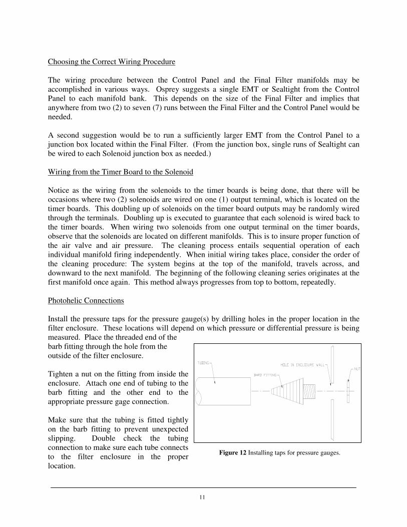
Install the pressure taps for the pressure gauge(s) by drilling holes in the proper location in the
filter enclosure. These locations will depend on which pressure or differential pressure is being
measured. Place the threaded end of the
barb fitting through the hole from the
outside of the filter enclosure.
Tighten a nut on the fitting from inside the
enclosure. Attach one end of tubing to the
barb fitting and the other end to the
appropriate pressure gage connection.
Make sure that the tubing is fitted tightly
on the barb fitting to prevent unexpected
slipping. Double check the tubing
connection to make sure each tube connects
to the filter enclosure in the proper
location.
Figure 12 Installing taps for pressure gauges.

12
Initial Checks
7. Check all fasteners to that they are properly tightened.
8. Check all electrical connections.
9. Check compressed air supply connections.
10. Check filter cartridges, making sure they are properly sealed against tube sheet panels.
11. Check all access doors, hatches, etc., to make sure that they are closed and properly secured.
13
OPERATION
Electrical Settings
Solenoid Sequence Setup
The timing setup between the firing of each solenoid, or pair of solenoids, should be set at ten
(10) seconds for the off time. The on time setting is 0.1 second. This allows the manifold to
recharge with air for the next solenoid firing.
Selector and Push Button Switch Operation
The Off-ON switch when turned to the �on position will allow the final filter to start
operating; this is indicated by the amper �Filter On light.
The �Photo-Timer selector switch is used as follows.
����PHOTO When the switch is on Photo, the final filter is controlled by the Photohelic Gauge
that is monitoring the final filter pressure, when the pressure exceeds the Photohelic preset high
pressure. The Final Filter will go thru a cleaning cycle until the pressure drops below the preset
low pressure setting on the photohelic and then will stop.
����Continuous Cycle Timer In the Timer position the continuous cycle timer controls the
duration that the Final Filter is cycling On and OFF, example: 5 minutes on and 15 minutes off.
When the cleaning process is in the off time and if the preset high pressure is reached the
cleaning process will begin and the photohelic gauge will override the timer �OFF sequence.
The cleaning process will continue until the low pressure preset is reached and then turn off.
����CYCLE Pressing the cycle push-button allows the Final Filter to cycle thru one complete
cycle and turn off. Cycle time should be set to the length of time it takes to complete one
cleaning cycle.
Startup
First, turn on the air supply to the air manifold and adjust the pressure from 80 psig to 100 psig.
Experience indicates 90 psig to be the typical setting for satisfactory cleaning performance.
Now, turn the switch on the electrical panel to �ON.
Compressed air is specified at a pressure of 90 psig. The control timer is factory set to clean a
segment of elements every 10 seconds. The control timer is factory set for a pulse width of 1/10
sec. These are the recommended operating specifications.

14
Adjustments other than these specified may result in poor cleaning performance or degradation
of the cartridge filter. Additional cleaning energy may be obtained by adjusting the pressure to a
maximum of 100 psig.
-WARNING- DO NOT increase airDO NOT increase airDO NOT increase airDO NOT increase air pressure beyond 100 psig or damage to the filter pressure beyond 100 psig or damage to the filter pressure beyond 100 psig or damage to the filter pressure beyond 100 psig or damage to the filter cartridges may result. cartridges may result. cartridges may result. cartridges may result.
The filter cleaning proceeds horizontally by rows and from left to right when facing the filter
clean air discharge.
MAINTENANCE
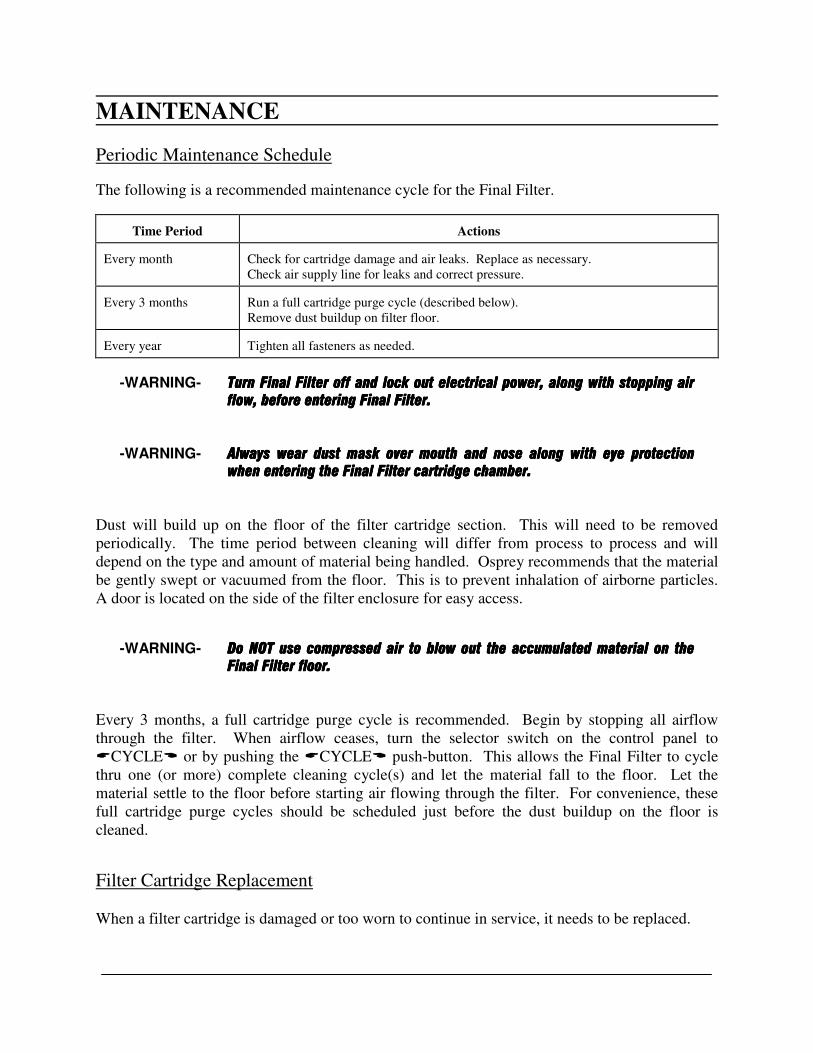
Periodic Maintenance Schedule
The following is a recommended maintenance cycle for the Final Filter.
Time Period
Actions
Every month
Check for cartridge damage and air leaks. Replace as necessary.
Check air supply line for leaks and correct pressure. Every 3 months
Run a full cartridge purge cycle (described below).
Remove dust buildup on filter floor. Every year
Tighten all fasteners as needed.
-WARNING- Turn Final Filter off and lock out electrical power, along with sTurn Final Filter off and lock out electrical power, along with sTurn Final Filter off and lock out electrical power, along with sTurn Final Filter off and lock out electrical power, along with stopping air topping air topping air topping air flow, before entering Final Filter. flow, before entering Final Filter. flow, before entering Final Filter. flow, before entering Final Filter.
-WARNING- Always wear dust mask over mouth and nose along with eye protection Always wear dust mask over mouth and nose along with eye protection Always wear dust mask over mouth and nose along with eye protection Always wear dust mask over mouth and nose along with eye protection
when entering the Final Filter cartridge chamber.when entering the Final Filter cartridge chamber.when entering the Final Filter cartridge chamber.when entering the Final Filter cartridge chamber.
Dust will build up on the floor of the filter cartridge section. This will need to be removed
periodically. The time period between cleaning will differ from process to process and will
depend on the type and amount of material being handled. Osprey recommends that the material
be gently swept or vacuumed from the floor. This is to prevent inhalation of airborne particles.
A door is located on the side of the filter enclosure for easy access.
-WARNING- Do NOT use compressed air to blow out the accumulated material on the Do NOT use compressed air to blow out the accumulated material on the Do NOT use compressed air to blow out the accumulated material on the Do NOT use compressed air to blow out the accumulated material on the Final Filter floor.Final Filter floor.Final Filter floor.Final Filter floor.
Every 3 months, a full cartridge purge cycle is recommended. Begin by stopping all airflow
through the filter. When airflow ceases, turn the selector switch on the control panel to
�CYCLE or by pushing the �CYCLE push-button. This allows the Final Filter to cycle
thru one (or more) complete cleaning cycle(s) and let the material fall to the floor. Let the
material settle to the floor before starting air flowing through the filter. For convenience, these
full cartridge purge cycles should be scheduled just before the dust buildup on the floor is
cleaned.
Filter Cartridge Replacement
When a filter cartridge is damaged or too worn to continue in service, it needs to be replaced.

15
16
-WARNING- Turn Final Filter off and lock out electrical power, along with stopping air Turn Final Filter off and lock out electrical power, along with stopping air Turn Final Filter off and lock out electrical power, along with stopping air Turn Final Filter off and lock out electrical power, along with stopping air flow, before entering Final Filter. flow, before entering Final Filter. flow, before entering Final Filter. flow, before entering Final Filter.
-WARNING- Always wear dust mask over mouth and nose along with eye protection Always wear dust mask over mouth and nose along with eye protection Always wear dust mask over mouth and nose along with eye protection Always wear dust mask over mouth and nose along with eye protection
when ewhen ewhen ewhen entering the Final Filter cartridge chamber.ntering the Final Filter cartridge chamber.ntering the Final Filter cartridge chamber.ntering the Final Filter cartridge chamber.
Enter the Final Filter through the door on the enclosure. Locate the filter cartridge to be
replaced. Remove the cartridge by turning the crank handle counter-clockwise and pulling the
crank handle from the end of the cartridge. Place a new filter cartridge in place, insert the crank
handle and rubber washer, and then tighten. See Figures 8 and 9, and the section titled �Filter
Cartridge Installation for more information.
-IMPORTANT- Do not over tighten the crank handles, as it may cause damage to the seal.Do not over tighten the crank handles, as it may cause damage to the seal.Do not over tighten the crank handles, as it may cause damage to the seal.Do not over tighten the crank handles, as it may cause damage to the seal.
17
SPARE PARTS LISTING
When ordering parts for your Final Filter. ALL of the following information must be
included. If you are ordering by phone, be sure to have this information available when
you place the call.
1.) Part number
2.) COMPLETE description of the part
3.) Product model number - this is ESSENTIAL
4.) Product serial number
5.) Quantity needed
6.) Length, size, color - where applicable
7.) Voltage, RPM, cycle (hertz), ratios, shaft size, etc.
8.) Shipping address and method
9.) Customer order number
Consult the spare parts quote that shipped with the Final Filter for specific information on
various parts. Contact Osprey Parts Department to place orders.