
Osprey 2 CFL125 - 150 - 180 - 220Gas Fired Floor Standing Boiler
Installation andServicing Instructions
Please leave these instructions with the user

2
Natural Gas
Potterton Osprey 2 CFL 125G.C.No 41 590 54
Potterton Osprey 2 CFL 150G.C.No 41 590 55
Potterton Osprey 2 CFL 180G.C.No 41 590 56
Potterton Osprey 2 CFL 220G.C.No 41 590 57
The boiler meets the requirements of StatutoryInstrument “ The Boiler (Efficiency) Regulations1993 No 3083” and is deemed to meet therequirements of Directive 92/42/EEC on the energyefficiency requirements for new hot water boilersfired with liquid or gaseous fuels:-
Type test for purpose of Regulation 5 certified by: Notified Body 0049.
Product/Production certified by:Notified Body 0049.
For GB/IE only.

3
1.0 Introduction 4
2.0 General Layout 5
3.0 Technical Data 6
4.0 Dimensions 7
5.0 System Details 8
6.0 Site Requirements 10
7.0 Installation 13
8.0 Commissioning the Boiler 15
9.0 Servicing the Boiler 17
10.0 Changing Components 19
11.0 Illustrated Wiring Diagram 23
12.0 Fault Finding 24
13.0 Short Parts List 28
Section Page
Contents

Potterton declare that no substances harmful to
health are contained in the appliance or used
during appliance manufacture.
1.1 Description
1. The Potterton Osprey 2 CFL is a fully automaticgas fired floor standing conventionally flued boilerwith a cast iron heat exchanger.
2. The boiler is designed for use with fully pumpedopen vented or sealed water systems with anindirect hot water cylinder.
3. The boiler is available in outputs of 35.0, 43.0,52.8 and 64.5kW
4. It is designed for use on Natural Gas (G20).
5. The boiler data badge is positioned on the boilerinner front panel.
6. The boiler is intended to be installed inresidential / commercial / light industrial E.M.C.environments on a governed meter supply only.
7. All systems must be thoroughly flushed andtreated with inhibitor (see section 6.2).
1.2 Installation
1. The appliance is suitable for installation only inG.B. and I.E. and should be installed in accordancewith the rules in force. For Ireland install inaccordance with I.S.813 “Installation of GasAppliances”. The installation must be carried out bya CORGI Registered Installer or other competentperson and be in accordance with the relevantrequirements of current Gas Safety (Installationand Use) Regulations, the Building Regulations(Scotland) (Consolidation), the Local BuildingRegulations, the Current I.E.E. Wiring Regulationsand the bye laws of the Local Water Undertaking.Where no specific instructions are given, referenceshould be made to the relevant BRITISHSTANDARD CODES OF PRACTICE.
1.0 Introduction
4
“Benchmark” Log Book
As part of the industry-wide “Benchmark” initiative all Baxi boilers nowinclude an Installation, Commissioning and Service Record Log Book.Please read the Log Book carefully and complete all sections relevant tothe appliance and installation. These include sections on the type ofcontrols employed, flushing the system, burner operating pressure etc.The details of the Log Book will be required in the event of any warrantywork. Also, there is a section to be completed at each subsequent regularservice visit. The Log Book must be left with the user.
Fig. 1
NOTE: This appliance must be installed inaccordance with the manufacturer’s instructionsand the regulations in force. Read the instructionsfully before installing or using the appliance.
Inner Front Panel
Data Badge

2.0 General Layout
5
2.1 Layout
1. Flue Spigot
2. Draught Diverter
3. Cable Clamp
4. Flue Safety Thermostat
5. Flow Connection
6. Return Connection
7. Burner
8. Gas Inlet Connection
9. Burner Ignition Control
10. Boiler Drain and Cap
11. Gas Valve
12. Burner Manifold
13. Pilot Feed Pipe
14. Pressure Test Point
15. Pilot
16. Overheat Thermostat
17. Boiler Thermostat
18. Inner Front Panel
19. Control Panel
20. Cleaning Brush
21. Heat Exchanger
22. Flue Hood
23. Boiler Safety Overheat Neon
24. Flame Failure Neon
25. Burner On Neon
26. Power On Neon
27. Boiler Safety Overheat Reset
28. Flame Failure Reset
29. On/Off Button
30. Temperature Control
RESET ON / OFF
Osprey 2 RESET
Fig. 2
1
2
3
4
5
6
7
8
910
11
12
13
14
15
16
17
18
19
20
21
22
23
27 30
2524
28 29
26
Fig. 3

3.0 Technical Data
6
Outercase Dimensions
Casing Height - 850mm
Casing Width (125) - 600mm
Casing Width (150) - 695mm
Casing Width (180) - 790mm
Casing Width (220) - 885mm
Casing Depth (125/150) - 600mm
Casing Depth (180/220) - 650mm
Clearances
LH Side 150mm Min
RH Side 150mm Min
Top 700mm Min
Front 700mm Min
Rear 200mm Min
Weights kg
125 140
150 170
180 200
220 230
Connections
Gas Supply - 22mm compression
Flow - 11/4” steel pipe, taper thread
Return - 11/4” steel pipe, taper thread
Recommended System
Temperature Drop 11°C 20°F
Maximum Flow Temperature
85°C
Heat Output 125 150
kW 35.0 43.0
Btu/h 119,443 146,745
180 220
kW 52.8 64.5
Btu/h 180,189 220,117
Electrical Supply 230V~ 50Hz Power Consumption 25W(excluding pump)External Fuse Rating 3AExternal Controls 230V switchingElectrical Protection IP20(Appliance must be connected to an earthed supply)
Appliance Category CAT 2H
Gas Rate 125 150
m3/h 4.0 5.06
ft3/h 142 179
180 220
m3/h 6.0 7.3
ft3/h 212 258
Burner Pressure 125 150
mbar 11.2 ± 0.4 11.4 ± 0.4
180 220
mbar 11.0 ± 0.4 11.8 ± 0.4
Inlet Pressure (Natural Gas Only)
mbar 20
in wg 8
Burner Injector 2.6mm Diameter
Appliance Type B11BS
NOx Class 150 & 180 3125 & 220 2
This value is used in the UK Government’s
Standard Assessment Procedure (SAP) for
energy rating of dwellings. The test data from
which it has been calculated have been
certified by 0049.
SEDBUK Declaration For Potterton Osprey 2 CFL
The seasonal efficiency (SEDBUK)125: 78.6 %150: 78.0 %180: 78.3 %220: 78.0 %
60
40
20
0
0 10 20 30 40 50 60
125
150
Flow Rate (l/min)
Pre
ssur
e D
rop
(mba
r)
70 80
125 and 150
60
80
100
120
40
20
0
0 10 20 30 40 50 60
180
220
Flow Rate (l/min)
180 and 220
Pre
ssur
e D
rop
(mba
r)
70 80 90 100 110 120
Heat Input (gross) 125 150
kW 43.07 53.28
Btu/h 146,983 181,827
180 220
kW 64.82 79.69
Btu/h 221,209 271,956Water Content litres
125 24
150 29
180 33
220 38
Working Head
Minimum 0.5m
Maximum 30m (3 bar)
Flue Spigot Diameter
125/150 184mm
180/220 241mm
Hydraulic Resistance Charts
Pilot Injector 0.45mm Diameter

4.0 Dimensions
7
Dimensions (mm)
A
600
695
790
885
Model
125
150
180
220
B
332.5
380
427.5
475
C
850
850
850
850
D
511
511
511
511
E
600
600
650
650
A
C
B
D
E
Front SideFig. 4 Fig. 5
F
F
184
184
241
241

5.0 System Details
8
5.1 Primary Circuit
1. The appliance is suitable for fully pumpedsystems only. The system can be open ventedor sealed.
2. A sealed system must incorporate thefollowing:-• Safety Valve • Pressure Gauge• Expansion Vessel• Filling PointReference must be made to the specific sectionsof BS5449 relating to sealed systems.
Treatment of Water Circulating Systems• All recirculatory water systems will be subjectto corrosion unless an appropriate watertreatment is applied. This means that theefficiency of the system will deteriorate ascorrosion sludge accumulates within the system,risking damage to pump and valves, boiler noiseand circulation problems.
• For optimum performance after installation thisboiler and its associated central heating systemmust be flushed in accordance with theguidelines given in BS 7593 “Treatment of waterin domestic hot water central heating systems”.
• This must involve the use of a proprietarycleanser, such as BetzDearborn Sentinel X300or X400, or Fernox Superfloc. Full instructionsare supplied with the products, but for immediateinformation please contact BetzDearborn (0151420 9563) or Fernox (01799 550 811) directly.
• For long term protection against corrosion andscale, after flushing it is recommended that aninhibitor such as BetzDearborn Sentinel X100,or Fernox MB-1 or Copal is dosed in accordancewith the guidelines given in BS 7593.
Failure to flush and add inhibitor to the systemmay invalidate the appliance warranty.
• It is important to check the inhibitorconcentration after installation, systemmodification and at every service in accordancewith the manufacturer’s instructions. (Test kitsare available from inhibitor stockists.)
• For information or advice regarding any of the above contact the Potterton Helpline.

5.0 System Details
9
5.2 Bypass
1. The boiler is fitted with a pump overrun devicewhich allows the removal of residual heat fromthe boiler. The system design must thereforealways provide an open circuit to allow watercirculation between the boiler flow and return.
2. Any bypass must be capable of allowing aminimum flow rate of 8l/min and be able todissipate at least 2kW.
5.3 System Control
1. The boiler is intended for use in a heatingsystem that incorporates external controls, i.e. aminimum of a timer device.
2. For optimum operating conditions andmaximum economy the fitting of room andcylinder thermostats is recommended.
3. The boiler should be controlled so that itoperates on demand only.

6.0 Site Requirements
10
6.1 Information
1. The installation must be carried out by aCORGI Registered Installer or other registeredcompetent person and be in accordance with therelevant requirements of the current Gas Safety(Installation and Use) Regulations, the BuildingRegulations (Scotland)(Consolidation), the LocalBuilding Regulations, the current I.E.E. WiringRegulations and the bye laws of the Local WaterUndertaking. Where no specific instruction isgiven reference should be made to the relevantBritish Standard Codes of Practice. For Irelandinstall in accordance with IS 813 “Installation ofGas Appliances”.
6.2 B.S. Codes of Practice
WARNING - The addition of anything thatmay interfere with the normal operation of theappliance without the express writtenpermission of Potterton could invalidate theappliance warranty and infringe the GasSafety (Installation and Use) Regulations.
6.3 Clearances (Fig. 6 & 7)
1. Minimum clearances must be provided aroundthe boiler as follows:-Each Side - 150mmTop - 700mmFront - 700mmRear - 200mm
Fig. 6
Fig. 7
STANDARDB.S. 6891B.S. 5440: Pt 1B.S. 5440: Pt 2B.S. 5546
B.S. 7074
B.S. 5449B.S. 6798
SCOPEGas Installation.Flues.VentilationInstallation of hot water suppliesfor domestic purposes.
Expansion vessels and ancillaryequipment for sealed water systems.
Forced circulation hot water systems.Installation of gas fired boilers.
700mm
700mm
700mm
200mm
150mm150mm
Minimum SideClearances
Minimum Front &Rear Clearances

6.0 Site Requirements
11
6.4 Location
1. The boiler must be positioned on a flat and levelfloor or base which must be capable of supportingthe full operational weight of the boiler. The fluemust pass through an outside roof or wall anddischarge to atmosphere in a position permittingsatisfactory removal of combustion products.
2. The boiler should be fitted within the buildingunless otherwise protected by a suitable enclosurei.e. garage or outhouse. (The 120 and 150 boilersmay be fitted inside a cupboard - see Section 6.7).
3. If the boiler or any part of the system is locatedin an area that may be subjected to low ambienttemperatures, it is recommended that a suitablefrost protection device is incorporated into thecontrol system.
4. If the boiler is fitted in a room containing a bathor shower reference must be made to the currentI.E.E. Wiring Regulations and BuildingRegulations. If the boiler is to be fitted into abuilding of timber frame construction thenreference must be made to the current edition ofInstitute of Gas Engineers Publication IGE/UP/7(Gas Installations in Timber Framed Housing).
6.5 Gas Supply
1. The gas installation should be in accordancewith BS6891.
2. The connection to the appliance is a 22mmcopper tail. This is connected to the gas servicecock (Fig. 9).
3. Ensure that the pipework from the meter to theappliance is of adequate size. Do not use pipes ofa smaller diameter than the boiler gas connection(22mm).
6.6 Electrical Supply
1. External wiring must be correctly earthed,polarised and in accordance with current I.E.E.Wiring Regulations.
2. The mains supply is 230V ~ 50Hz fused at 3A.
NOTE: The method of connection to the electricity
supply must facilitate complete electrical isolation
of the appliance.
Connection may be via a fused double-pole
isolator with a contact separation of at least 3mm
in all poles and servicing the boiler and system
controls only.
Fig. 8
Fig. 9
Gas Cock

6.0 Site Requirements
12
6.7 Flues & Ventilation
1. The room or space of installation must beventilated to ensure the correct and safeoperation of the boiler.
2. 125 and 150 models require one air vent, athigh or low level. High and low level vents arerequired for 180 and 220 models. The vents musthave a free area as follows:-
125 models 163cm2
150 models 208cm2
180 models 281cm2 (high)180 models 562cm2 (low)220 models 315cm2 (high)220 models 630cm2 (low)
3. The vent(s) must communicate directlybetween outside and the room or space ofinstallation, or using suitable ducting (all models)or indirectly via an opening of at least the samearea (125 and 150 models only).
4. 125 and 150 models may be fitted in acupboard or compartment within the room orspace of installation providing the cupboard orcompartment is ventilated as follows:-
125 models 388cm2 (high)125 models 776cm2 (low)150 models 478cm2 (high)150 models 956cm2 (low)
Both vents must communicate with the sameroom or be on the same wall to outside air.
5. 180 and 220 models cannot be fitted in acompartment except of the type specified inBS6644 using a monodraught system.
6. The flue system should be lined throughout itslength.
7. Minimum flue length is 1m. There should be atleast 1m of vertical flue from the boiler fluesocket, and horizontal runs and 90° bends shouldbe avoided.
8. If an existing chimney is used it must be fullyswept before lining or connecting the boiler.Precautions should be taken to avoidcondensation forming in the flue.
9. The flue diameter must be at least the samediameter as the connection on the boiler draughtdiverter.
10. A short length of purpose made flue may berequired to connect the boiler flue spigot to theflue system.
11. The flue terminal must be of an approvedtype and be positioned above roof level.

7.0 Installation
13
7.1 Initial Preparation
The gas supply, gas type and pressure mustbe checked for suitability before connection.
1. Ensure that the floor or base on to which theboiler is to be fitted is clean and free from debris.
2. Install any pipework that will be behind theboiler, and any appropriate flue components.
3. Manoeuvre the boiler into position, seekingassistance as necessary. Check the clearancesas shown in Section 6.3.
4. Undo the two securing screws and remove thetop panel.
5. Disengage the front panel from the retainingmagnets and hinge forwards. Unhook the panelfrom the lower hinge pins (Fig. 10) and place tothe right hand side, taking care not to stretch theearth wire.
6. Remove the flue spigot from inside the caseand fit it to the boiler draught diverter (Fig. 11). Important: Only use the flue spigot supplied.Do not use a proprietary item.
7. Connect the gas supply pipe and the systemflow and return connections to the boiler (Fig. 12).
8. Connect the flue system to the flue spigot. Anyflue pipe must be at least the same diameter asthe connection on the boiler draught diverter
SecuringScrews
Top Panel
Magnets
Front Panel
Flue Spigot
ReturnConnection
Gas Inlet
FlowConnection
Fig. 10
Fig. 11
Fig. 12
Boiler DraughtDiverter Connection

7.0 Installation
14
7.2 Making the Electrical Connection
1. Undo the two securing screws from the rearof the top panel. Remove the panel (Fig. 13).
2. Swivel the two retaining plates through 90°.Lift the control box slightly and allow it to hingeforwards (Figs. 14 & 15). Undo the two retainingscrews and remove the cover panel.
3. The input wiring to the boiler and the pumpfeed from the boiler should be routed throughthe grommet/clamps in the control box rearpanel (Fig. 16).
4. Remove the clamps from the panel and slitthe grommets with a suitable knife or blade.
5. Determine the length of the wiring and securein the clamps.
6. Connect live, neutral, earth, and switched liveto L, N, & SL of the terminal strip. The pumplive, neutral and earth should be connected toPL, PN & of the terminal strip (Fig. 17).
1.4
SecuringScrews
Top Panel
Front Panel
Cover Panel
Fig. 13
Fig. 15
Fig. 16
LNLHT
SW
L
View inside control box with coverpanel removed.
Terminal Strip Earth PointBurner Ignition
ControlConnection
Cable Clamps
Grommet
TemperatureControl
Thermostat
Fig. 14
LNLHT
SW
L
Fig. 17 Terminal Strip
Magnets
SafetyThermostat

8.0 Commissioning the Boiler
15
8.1 Commissioning the Boiler
1. Reference should be made to BS 5449Section 5 when commissioning the boiler.
2. Open the water supply to the boiler.
3. The system must be flushed in accordancewith BS 7593, Section 5.1 of these instructionsand the flushing agent manufacturersinstructions.
4. Turn the gas supply on and purge the systemaccording to BS 6891.
5. Test for gas soundness.
8.2 Checking the Burner Pressure
1. Slacken the pressure test point sealing screwand connect a pressure gauge (Fig. 19).
2. Turn on the gas and electrical supplies to theboiler and ensure that all external controls arecalling for heat.
3. Set the temperature control to maximum (Fig. 18).
4. Check the burner setting pressure (seeSection 4.0 “Technical Data”).
5. If necessary adjust the pressure by removingthe gas valve governor cover and turning thescrew to achieve the required pressure (Fig. 20).
5. Turn the boiler off and reassemble in reverseorder. Tighten the pressure test point sealingscrew (Fig. 19).
Thermostat Knob
Fig. 19
Fig. 18
Fig. 20
LH View of GasValve
Governor Cover Screw
Inlet Pressure Test Point
Burner Pressure Test Point

8.0 Commissioning the Boiler
16
8.3 Completion
1. Flush the system again and treat it inaccordance with BS7593, Section 5.1 of theseinstructions and the flushing agent and inhibitormanufacturer’s instructions.
2. Carefully read and complete all sections of the“Benchmark” Installation, Commissioning andService Record Log Book that are relevant to theappliance and installation. The details of the LogBook will be required in the event of anywarranty work. The Log Book must be handed tothe user for safe keeping and each subsequentregular service visit recorded.
3. Instruct the user in the operation of the boilercontrols and the function and resetting of thevarious safety devices
4. Hand over the User’s Operating, Installationand Servicing Instructions and the Log Book,giving advice on the necessity of regularservicing.
5. Refit the outercase front and top panels (Fig. 21).
SecuringScrews
Top Panel
Front Panel
Fig. 21
Magnets
9.0 Servicing the Boiler
17
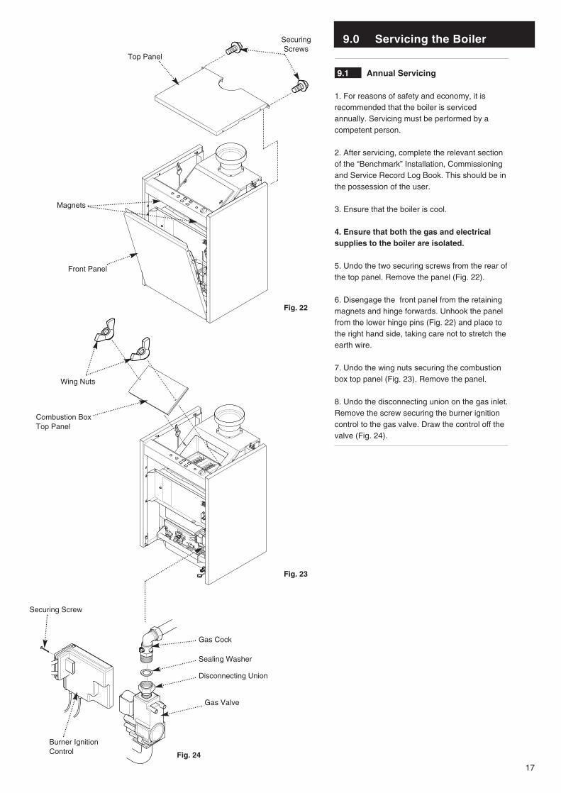
9.1 Annual Servicing
1. For reasons of safety and economy, it isrecommended that the boiler is servicedannually. Servicing must be performed by acompetent person.
2. After servicing, complete the relevant sectionof the “Benchmark” Installation, Commissioningand Service Record Log Book. This should be inthe possession of the user.
3. Ensure that the boiler is cool.
4. Ensure that both the gas and electricalsupplies to the boiler are isolated.
5. Undo the two securing screws from the rear ofthe top panel. Remove the panel (Fig. 22).
6. Disengage the front panel from the retainingmagnets and hinge forwards. Unhook the panelfrom the lower hinge pins (Fig. 22) and place tothe right hand side, taking care not to stretch theearth wire.
7. Undo the wing nuts securing the combustionbox top panel (Fig. 23). Remove the panel.
8. Undo the disconnecting union on the gas inlet.Remove the screw securing the burner ignitioncontrol to the gas valve. Draw the control off thevalve (Fig. 24).
SecuringScrews
Top Panel
Front Panel
Wing Nuts
Combustion BoxTop Panel
Burner IgnitionControl
Securing Screw
Gas Valve
Disconnecting Union
Sealing Washer
Gas Cock
Fig. 22
Fig. 23
Fig. 24
Magnets

9.0 Servicing the Boiler
18
9.1 Annual Servicing (Cont)
9. Undo the two nuts securing the valve, injectormanifold and burner assembly to the boiler(Figs. 25 & 27).
10. Hold the manifold and carefully draw theassembly away from the boiler. Retain thewasher from the gas inlet connection.
11. Brush any dirt or debris from the burnerskins. Examine the burners for blocked ports.Any blockage can be removed using a fine wirebrush.
12. Inspect the pilot assembly, electrodes andinjectors (Fig. 26). Replace if necessary.
13. Ensure that the spark and sensing leads areclipped into the separation brackets and do notcross over each other.
14. Slide a suitable sheet of paper or cloth underthe boiler heat exchanger (Fig. 29).
15. Unclip the brush from the top edge of the lefthand side panel clean between the boiler fins(Fig. 28 & 29). Check for any blockage.
16. Carefully withdraw the sheet and dispose ofin a proper manner. Check under the boiler andremove any fallen dirt or debris.
17. Reassemble in reverse order of dismantlingand recommission.
18. Complete the relevant section of the“Benchmark” Installation, Commissioning andService Record Log Book and hand it back tothe user.
Securing Nuts
Manifold
Pilot Assembly
Fig. 25
Fig. 26
Fig. 27
Fig. 28
Fig. 29
Sheet of Paper
Burner Skin
Cleaning Brush
Heat Exchanger Fins

10.0 Changing Components
19
IMPORTANT: When changing componentsensure that both the gas and electricalsupplies to the boiler are isolated before anywork is started.
Undo the two securing screws from the rear ofthe top panel. Remove the panel (Fig. 30).
Disengage the retaining magnets at the top ofthe front panel and hinge forwards. Unhook thepanel from the lower hinge pins (Fig. 30).
10.1 Boiler Thermostat
1. Swivel the two retaining plates (Fig. 31)through 90°. Lift the control box slightly andallow it to hinge forwards. Undo the two retainingscrews and remove the cover panel (Fig. 32).
2. After noting their position remove the wiresfrom the thermostat body. Turn the thermostatknob fully anticlockwise and pull it off (Fig. 33).
3. Remove the screws securing the thermostatto the control panel and pull off the earth wire(Fig. 34).
4. Pull the spring clip off the thermostat pocket.Withdraw both the boiler and overheatthermostat phials and the spacer tube from thepocket (Fig. 33).
5. Take the new thermostat and turn theoperating shaft fully anticlockwise.
6. Reassemble in reverse order. The securingscrew incorporating the pin must be used on theright (Fig. 34). Ensure both phials and the spacertube are pushed fully into the thermostat pocketand the capillaries are retained by the clip.
SecuringScrews
Top Panel
Front Panel
Cover Panel
Spring Clip
Spacer Tube
Securing Screw
Earth Wire
Thermostat
Securing Pin Screw
ControlKnob
Thermostat
Phials
Fig. 30
Fig. 31
Fig. 33
Fig. 34
Fig. 32
Magnets

10.0 Changing Components
20
10.2 Boiler Safety Thermostat
1. Swivel the two retaining plates through 90°.Lift the control box slightly and allow it to hingeforwards. Undo the two retaining screws andremove the cover panel (Figs. 35 & 37).
2. After noting their position pull the wires fromthe thermostat body (Fig. 38).
3. Remove the locknut securing the thermostatto the control panel (Fig. 38).
4. Pull the spring clip off the thermostat pocket.Withdraw both the boiler and overheatthermostat phials and the spacer tube from thepocket (Fig. 36).
5. Reassemble in reverse order, ensuring bothphials and the spacer tube are pushed fully intothe thermostat pocket and the capillaries areretained by the clip.
10.3 Gas Valve
1. Undo the disconnecting union on the gas inlet.Remove the screw securing the burner ignitioncontrol to the gas valve. Draw the control off thevalve (Fig. 39).
2. Undo the two nuts securing the valve, injectormanifold and burner assembly to the boiler (Fig.40).
3. Hold the manifold and carefully draw theassembly away from the boiler. Retain thewasher from the gas inlet connection.
4. Undo the pilot feed pipe from the gas valve,and slacken it at the pilot burner to allow it toswing clear.
5. Undo the four screws securing the gas valveto the injector manifold. Remove the valve andseal (Fig. 41).
6. Check the condition of the seal previouslyremoved before fitting the new valve to theinjector manifold. Replace as necessary.
7. Reassemble in reverse order and check thecondition of the seal to be used on thedisconnecting union. Replace as necessary.
Securing Nuts
Manifold
Fig. 37
Fig. 40
Fig. 41
Gas Valve
Quad Seal
Burner Manifold
Valve SecuringScrews
Burner Ignition
Control
Securing Screw
Gas Valve
Disconnecting Union
Sealing Washer
Gas Cock
Fig. 39
Spring ClipThermostat
Phials
Spacer TubeFig. 36
Fig. 35
Lock Nut
Safety Thermostat
Fig. 38

10.0 Changing Components
21
10.4 Burner(s)
1. Undo the disconnecting union on the gasinlet. Remove the screw securing the burnerignition control to the gas valve. Draw thecontrol off the valve (Fig. 43).
2. Undo the two nuts securing the valve, injectormanifold and burner assembly to the boiler.
3. Hold the manifold and carefully draw theassembly away from the boiler. Retain thewasher from the gas inlet connection.
4. Carefully draw the insulation piece away overthe burners (Fig. 44).
5. Undo the screws securing the burner(s) to bereplaced. Remove the burner(s) (Fig. 44).
6. Reassemble in reverse order, replacing theinsulation piece if it is damaged.
10.5 Injector(s) (Figs. 44 & 45)
1. Using a suitable spanner undo from themanifold the injector(s) to be replaced.
2. Reassemble in reverse order using a newsealing washer for each injector.
10.6 Pilot Assembly
1.Disconnect and remove the pilot feed pipe.Pull the electrode leads off the gas valve burnerignition control and unclip them from theseparation brackets.
2. Undo the pilot bracket securing screws.Withdraw the bracket from the burner mountingplate. Carefully remove the pilot injector fromthe bracket (Figs. 44 & 46).
3. Inspect the injector and replace if it is blockedor damaged. Check the condition of the pilotbracket sealing gasket and replace if necessary.
4. The new pilot assembly must be fitted asshown, with the spark electrode to the right(Fig. 46).
5. Clip the electrode leads into the separationbrackets. Ensure that the leads do not crossover each other.
6. Reassemble in reverse order.
Manifold
Burner
SecuringScrews
Injector and Washer
Pilot Feed Pipe
Pilot Injector
Fig. 42
Fig. 44
Fig. 45
Fig. 46
Insulation
Pilot Bracket
Sealing Gasket
Securing Screw
Gas Valve
Disconnecting Union
Sealing Washer
Gas Cock
Fig. 43
Burner Ignition
Control
Spark Electrode

10.0 Changing Components
22
10.7 Flue Safety Thermostat
1. Undo the nut securing the Flue SafetyThermostat to the draught diverter. Ease thecable clamp from the slot in the draught diverter(Figs. 47 & 48).
2. Undo the screw retaining the earth wire to theboiler and disconnect the plug on the FlueSafety Thermostat cable from the boiler harness(Fig. 49).
3. Reassemble in reverse order. Check theoperation of the Safety Thermostat by cappingthe flue. The boiler should extinguish withinthree minutes.
10.8 Burner Ignition Control (Fig. 50)
1. Remove the screw securing the burnerignition control to the gas valve. Draw thecontrol off the valve.
2. Pull the electrode leads off the burner ignitioncontrol.
3. Prise apart the three barbs securing thecontrol cover. Remove the cover.
4. Undo the screws securing the cable clamp tothe control and disconnect the edge connectorfrom the control P.C.B.
5. Fit the new burner ignition control andreassemble in reverse order.
Flue Safety
Thermostat
Fig. 47
Flue Safety Thermostat
Earth RetainingScrew
Spark Electrode
Cable Clamp
Edge Connector
Sensing Electrode
Burner Ignition Control
Draught Diverter
Securing Nut
Cable Clamp
Fig. 48Fig. 49
Fig. 50

11.0 Illustrated Wiring Diagram
23
Key to Wiring
b - bluew - white
LNSL
Control Thermostat
Power ON Neon(orange)Burner ON Neon
(green)
Flame Failure Neon(Red)
Safety Thermostat
Safety Thermostat Neon(red)
Pilot Assembly
Flue ProductsSafety Thermostat
Burner Ignition Control
Flame FailureReset Button
ON / OFFButton
External Pump
w 21
w 20
w 28
w 40
w 72w 71
w 42
w 42
w 61
w 67
b 50
b 50
w 29w 28
b 50
w 27
b 30
b 50
w 66
b
bb

24
12.0 Fault Finding
10 42
68 12 3
11 1
B C DA
F G HE
K L MJ
Boiler Harness Burner Ignition Controller Socket
The following table indicates which wires from the mainharness are connected to the socket.
PositionABCDEFGHJKLM
View of Socket end on
Burner Ignition Controller Harness Plug
Numbers refer to pin position on edge connector atBurner Ignition Controller to which this plug isconnected. Dotted lines indicate link wires.
View of Harness Plug end on
Wire IdentificationW20
W41 (linked to H)W66B50W29B30
Neutral to ‘N’ on Terminal StripW41 (linked to B)
W28W67EarthW61
12.1 Fault Finding
1. This page shows the configuration of the plugand socket on the Burner Ignition Control supply(Fig. 51). The socket is part of the boiler harnessand the plug is on the lead connected to theBurner Ignition Control.
2. Fig. 52 illustrates the layout of the edgeconnector on the Burner Ignition Control.
Fig. 51
12 11 10 9 8 7 6 5 4 3 2 1
Numbers correspond to pins onBurner Ignition Controller
Layout of Edge Connector on Ignition Controller Harness
1 & 11- Neutral5 & 9 - Linked7 - Unused12 - Earth
Fig. 52

25
12.0 Fault Finding
Is there permanent live to the boiler?
Is the “Power On” neonilluminated ?
NO
YES
NO
YES
Is there 230V at L & Nconnections on the neon?
Electrical fault external toboiler
Replace neon
CARRY OUT THE FOLLOWING PRELIMINARY CHECKS BEFORECOMMENCING FAULT FINDING1. Check that gas, water and electrical supplies are available at the boiler.Electrical supply = 230V ~ 50 Hz. The preferred minimum gas pressure is19.5mbar (natural gas).2. Carry out electrical system checks, i.e. Ground Continuity, Resistance toGround, Short Circuit and Polarity with a suitable meter. Note: Repeat thesechecks after servicing or fault finding.3. Ensure all external controls are calling for heat and check all external andinternal fuses. Before servicing or replacement of parts ensure the gas andelectrical supplies are isolated.
YES Does the On/Off buttonilluminate when pressed in?
Is there 230V at L & N ofthe On/Off button?
NO
START
NO
Is there 230V at SWL & Non terminal strip?
Check supply fromexternal controls
YES
Replace On/Off Button
NO
Check boiler internalwiring
YES
NO
Internal electrical fault onboiler
YES
26
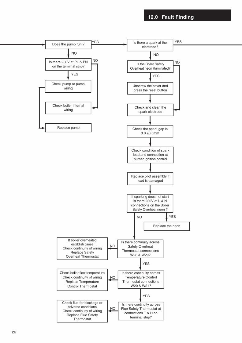
12.0 Fault Finding
Is there a spark at theelectrode?
NO
Check and clean thespark electrode
Check condition of sparklead and connection atburner ignition control
Replace pilot assembly iflead is damaged
Check the spark gap is 3.0 ±0.5mm
Is the Boiler SafetyOverheat neon illuminated?
Unscrew the cover andpress the reset button
YES
If sparking does not startis there 230V at L & N
connections on the BoilerSafety Overheat neon ?
Replace the neon
YES
Is there continuity acrossSafety Overheat
Thermostat connectionsW28 & W29?
NO
NO
Is there continuity acrossTemperature Control
Thermostat connectionsW20 & W21?
YES
Is there continuity acrossFlue Safety Thermostat at
connections T & H onterminal strip?
YES
NO
NO
YESDoes the pump run ?
NO
Is there 230V at PL & PNon the terminal strip?
YES
Check pump or pumpwiring
Check boiler internalwiring
NO
YES
Replace pump
NO
Check flue for blockage oradverse conditions
Check continuity of wiring Replace Flue Safety
Thermostat
Check boiler flow temperatureCheck continuity of wiring
Replace TemperatureControl Thermostat
If boiler overheated establish cause
Check continuity of wiring Replace Safety
Overheat Thermostat

12.0 Fault Finding
27
Does the pilot burnerflame light ?
Does the spark continuefor 25 seconds?
NO
Is there 20mb pressure atGas Valve inlet?
YES
Is there gas at the pilotfeed tapping on the Valve?
Is the Pilot Feed Pipe orPilot Burner Injector
blocked? If so, clean or replace
NO
Check & rectify supply
Remove Burner IgnitionControl from valve
Is resistance across pilotsolenoid connections V1
4.3 kohm ±10%? If not, replace gas valve
YES NO
YES NO
NO
Is there 20mb pressure atGas Valve inlet?
Check & rectify supply
NOYES
Check and adjust theburner pressure to that
stated in Technical Data
Do the main burners light ?YES Does the boiler shut down
when the flowtemperature reaches 85°?
YES
NO
YES BOILEROPERATINGCORRECTLY
Is the flame failure neonilluminated?
Press reset button
YES NO
Is there 230V at L & Nconnections on the neon?
Replace the neon
YES
Is there gas at the burnerpressure test point?
YES
NO
Remove Burner IgnitionControl from valve
Is resistance across mainsolenoid connections V2
3.9 kohm ±10%? If not, replace gas valve
NOReplace gas valve
YES
Remove cover from Burner Ignition Control
Is there 230V across pins10 & 11 of edge connector?
YES Replace Burner IgnitionControl
NO
Check boiler internal wiring
Ensure control knob is fullyclockwise and the
thermostat phial is correctlyfitted in the pocket
Replace TemperatureControl Thermostat
Pilot SolenoidConnections
Main SolenoidConnections

Potterton, Baxi UK Limited, Brownedge Road, Bamber Bridge, Preston, Lancashire. PR5 6SNAfter Sales Service 08706 096 096 Technical Enquiries 08706 049 049
www.baxi.comComp. No. 5106752 - Iss. 1 - 01/02PO890A0
13.0 Short Parts List
Short Parts List
Key G.C. Description ManufacturersNo. No. Part No.
226 Gas Valve Assembly V501790
201 E03-614 Burner V17000837
228 E03-653 Main Burner Injector V17003199
229 E03-652 Injector Washer V17006504
321 Control Thermostat V133624
234 Safety Thermostat V17006955
215 Pilot Burner Assembly V133535
235 Burner Ignition Control V17000601
322 Flue Products Safety Thermostat V500540
219 Pilot Injector V17003216
201
235
226
215
228
219
322
234
321
229


![Osprey - Aerospace - Tiger Squadrons [Osprey - Aerospace].pdf](https://cdn.vdocuments.mx/doc/165x107/55cf9675550346d0338b9dbe/osprey-aerospace-tiger-squadrons-osprey-aerospacepdf.jpg)
