
Oracle® Fusion MiddlewareApplication Adapter for SAP R/3 (SAP JCo 3.0) User's Guide for Oracle WebLogic Server
11g Release 1 (11.1.1.3.0)
E17656-03
November 2010

Oracle Fusion Middleware Application Adapter for SAP R/3 (SAP JCo 3.0) User's Guide for Oracle WebLogic Server, 11g Release 1 (11.1.1.3.0)
E17656-03
Copyright © 2009, 2010, Oracle and/or its affiliates. All rights reserved.
Primary Author: Stefan Kostial
Contributing Authors: Sunil Gopal, Marian Jones, Vikas Anand, Sunil Wadhwa, Vishal Saxena, Vimmika Dinesh
This software and related documentation are provided under a license agreement containing restrictions on use and disclosure and are protected by intellectual property laws. Except as expressly permitted in your license agreement or allowed by law, you may not use, copy, reproduce, translate, broadcast, modify, license, transmit, distribute, exhibit, perform, publish, or display any part, in any form, or by any means. Reverse engineering, disassembly, or decompilation of this software, unless required by law for interoperability, is prohibited.
The information contained herein is subject to change without notice and is not warranted to be error-free. If you find any errors, please report them to us in writing.
If this software or related documentation is delivered to the U.S. Government or anyone licensing it on behalf of the U.S. Government, the following notice is applicable:
U.S. GOVERNMENT RIGHTS Programs, software, databases, and related documentation and technical data delivered to U.S. Government customers are "commercial computer software" or "commercial technical data" pursuant to the applicable Federal Acquisition Regulation and agency-specific supplemental regulations. As such, the use, duplication, disclosure, modification, and adaptation shall be subject to the restrictions and license terms set forth in the applicable Government contract, and, to the extent applicable by the terms of the Government contract, the additional rights set forth in FAR 52.227-19, Commercial Computer Software License (December 2007). Oracle USA, Inc., 500 Oracle Parkway, Redwood City, CA 94065.
This software is developed for general use in a variety of information management applications. It is not developed or intended for use in any inherently dangerous applications, including applications which may create a risk of personal injury. If you use this software in dangerous applications, then you shall be responsible to take all appropriate fail-safe, backup, redundancy, and other measures to ensure the safe use of this software. Oracle Corporation and its affiliates disclaim any liability for any damages caused by use of this software in dangerous applications.
Oracle is a registered trademark of Oracle Corporation and/or its affiliates. Other names may be trademarks of their respective owners.
This software and documentation may provide access to or information on content, products, and services from third parties. Oracle Corporation and its affiliates are not responsible for and expressly disclaim all warranties of any kind with respect to third-party content, products, and services. Oracle Corporation and its affiliates will not be responsible for any loss, costs, or damages incurred due to your access to or use of third-party content, products, or services.

iii
Contents
Preface ................................................................................................................................................................ vii
Audience...................................................................................................................................................... viiDocumentation Accessibility .................................................................................................................... viiRelated Documents ................................................................................................................................... viiiConventions ............................................................................................................................................... viii
1 Introduction
Adapter Features....................................................................................................................................... 1-1Supported Versions and Platforms ................................................................................................. 1-2
Classical SAP Technologies for ABAP................................................................................................. 1-2Integration with SAP R/3 ........................................................................................................................ 1-3Adapter Architecture ............................................................................................................................... 1-4BSE Versus Oracle Adapter J2CA Deployment ................................................................................. 1-6
2 Getting Started
Verifying the SAP Java Connector (SAP JCo) .................................................................................... 2-1Verifying SAP JCo on Windows Platforms .................................................................................... 2-1Verifying SAP JCo on UNIX Platforms........................................................................................... 2-2
Identifying SAP R/3 Logon Parameters ............................................................................................... 2-3User Parameters ................................................................................................................................. 2-3System Settings (Application Server) Parameters ......................................................................... 2-4System Settings (Message Server) Parameters............................................................................... 2-4Connection Pool Parameters ............................................................................................................ 2-5SAP Gateway Parameters ................................................................................................................. 2-5ALE Parameters.................................................................................................................................. 2-5Global Processing Parameters .......................................................................................................... 2-6SNC Parameters ................................................................................................................................. 2-7
3 SAP Java Connector 3.0 Considerations
Supported Platforms................................................................................................................................ 3-1Connection Management........................................................................................................................ 3-1Connection Pooling.................................................................................................................................. 3-2Server Threads .......................................................................................................................................... 3-2Single Server Support ............................................................................................................................. 3-2Changing Parameters and Table Parameters ...................................................................................... 3-3

iv
Trace Level Parameter ............................................................................................................................. 3-3
4 Configuring Oracle Application Adapter for SAP R/3
Starting Application Explorer ................................................................................................................ 4-1Configuring Repository Settings .......................................................................................................... 4-2Creating a Repository Configuration ................................................................................................... 4-2
Creating a Configuration for BSE .................................................................................................... 4-2Creating a Configuration for J2CA.................................................................................................. 4-3Connecting to a BSE or J2CA Configuration.................................................................................. 4-5
Establishing a Connection (Target) for SAP R/3 ................................................................................ 4-5Defining a Target to SAP R/3 .......................................................................................................... 4-5Connecting to a Defined SAP R/3 Target ................................................................................... 4-12Managing a Connection to SAP R/3 ............................................................................................ 4-12
Viewing Application System Objects ............................................................................................... 4-14Creating XML Schemas ........................................................................................................................ 4-14Generating WSDL (J2CA Configurations Only)............................................................................. 4-15Creating and Testing a Web Service (BSE Configurations Only) ............................................... 4-16Configuring an Event Adapter ........................................................................................................... 4-19
Creating and Editing a Channel.................................................................................................... 4-19Schema Validation .......................................................................................................................... 4-24
5 Oracle WebLogic Server Deployment and Integration
Adapter Integration with Oracle WebLogic Server ........................................................................... 5-1Deployment of Adapter .......................................................................................................................... 5-1Updating Adapter Configuration.......................................................................................................... 5-2
6 Integration With BPEL Service Components in the Oracle SOA Suite
Overview .................................................................................................................................................... 6-1Deployment of Adapter .......................................................................................................................... 6-1Configuring a New Application Server Connection ......................................................................... 6-2Designing an Outbound BPEL Process for Service Integration...................................................... 6-7
Generating WSDL for Request/Response Service ........................................................................ 6-8Creating an Empty Composite for SOA ......................................................................................... 6-9Defining a BPEL Outbound Process............................................................................................. 6-12Deploying the BPEL Outbound Process ...................................................................................... 6-33Invoking the Input XML Document in the Oracle Enterprise Manager Console.................. 6-37Testing Outbound BPEL and Mediator Processes ..................................................................... 6-40
Designing an Inbound BPEL Process for Event Integration......................................................... 6-41Generating WSDL for Event Integration ..................................................................................... 6-41Creating an Empty Composite for SOA ...................................................................................... 6-48Defining a BPEL Inbound Process................................................................................................ 6-50Deploying the BPEL Inbound Process ......................................................................................... 6-59Triggering an Event in SAP R/3 ................................................................................................... 6-65
7 Integration With Mediator Service Components in the Oracle SOA Suite
Configuring a New Application Server Connection ......................................................................... 7-2

v
Configuring a Mediator Outbound Process........................................................................................ 7-2Creating an Empty Composite for SOA ......................................................................................... 7-2Defining a Mediator Outbound Process ......................................................................................... 7-4Deploying the Mediator Outbound Process ............................................................................... 7-20Invoking the Input XML Document in the Oracle Enterprise Manager Console.................. 7-25
Configuring a Mediator Inbound Process........................................................................................ 7-27Creating an Empty Composite for SOA ...................................................................................... 7-27Defining a Mediator Inbound Process ......................................................................................... 7-29
8 Integration With BPM Service Components in the Oracle SOA Suite
Overview .................................................................................................................................................... 8-1Deployment of Adapter .......................................................................................................................... 8-1Configuring a New Application Server Connection ......................................................................... 8-2Designing an Outbound BPM Process Using Transformations for Service Integration ........... 8-2
Creating an Empty Composite for BPM ......................................................................................... 8-2Defining a BPM Outbound Process................................................................................................. 8-4Deploying the BPM Outbound Process ....................................................................................... 8-47Invoking the Input XML Document in the Oracle Enterprise Manager Console.................. 8-50Workaround for J2CA BPM Processing When Using BAPI or RFC Objects.......................... 8-54
Designing an Inbound BPM Process Using Transformations for Event Integration .............. 8-63Creating an Empty Composite for BPM ...................................................................................... 8-63Defining a BPM Inbound Process ................................................................................................. 8-65
9 Configuring Outbound and Inbound Processing Using Oracle Service Bus
Overview of Application Adapter Integration with Oracle Service Bus ...................................... 9-1Configuring Outbound Processing Using Oracle Service Bus (J2CA Configuration) ............... 9-1
Starting Oracle Service Bus and Creating Project Folders ........................................................... 9-2Setting the Class Path for Application Explorer to Integrate With Oracle Service Bus........... 9-5Publishing a WSDL From Application Explorer to Oracle Service Bus..................................... 9-5Configuring a File Type Business Service ...................................................................................... 9-9Configuring a Proxy Service.......................................................................................................... 9-14Configuring a Pipeline ................................................................................................................... 9-18
Configuring Inbound Processing Using Oracle Service Bus (J2CA Configuration) ............... 9-28Starting Oracle Service Bus and Creating Project Folders ........................................................ 9-28Setting the Class Path for Application Explorer to Integrate With Oracle Service Bus........ 9-31Publishing a WSDL From Application Explorer to Oracle Service Bus.................................. 9-31Configuring a File Type Business Service ................................................................................... 9-37Configuring a Pipeline ................................................................................................................... 9-42
Configuring Outbound Processing Using Oracle Service Bus (BSE Configuration) .............. 9-46Starting Oracle Service Bus and Creating Project Folders ........................................................ 9-47Setting the Class Path for Application Explorer to Integrate With Oracle Service Bus........ 9-50Publishing a WSDL From Application Explorer to Oracle Service Bus.................................. 9-50Configuring a File Type Business Service ................................................................................... 9-52Configuring a WSDL Type Business Service .............................................................................. 9-55Configuring a Proxy Service.......................................................................................................... 9-60Configuring a Pipeline ................................................................................................................... 9-63

vi
10 Troubleshooting and Error Messages
Troubleshooting .................................................................................................................................... 10-1BSE Error Messages .............................................................................................................................. 10-5
General Error Handling in BSE..................................................................................................... 10-5Adapter-Specific Error Handling.................................................................................................. 10-6
11 Advanced User Tools
Web Services Policy-Based Security.................................................................................................. 11-1Configuring Web Services Policy-Based Security ...................................................................... 11-2
Migrating Repositories......................................................................................................................... 11-8
A Understanding the SAP System Role in Remote Processing
Functionality of the Adapter ................................................................................................................. A-1Roles .................................................................................................................................................... A-1Client ................................................................................................................................................... A-2Server .................................................................................................................................................. A-2
SAP Inbound Message Processing....................................................................................................... A-2Configuring SAP R/3 Inbound Processing................................................................................... A-4Configuring a Logical System ......................................................................................................... A-5Configuring a Distribution Model for a Logical System............................................................. A-9Defining a Partner Profile .............................................................................................................. A-12
SAP Outbound Message Processing ................................................................................................. A-16SAP Gateway ................................................................................................................................... A-17Program IDs and Load Balancing................................................................................................. A-17Registering a RFC Destination and Program ID in SAP GUI................................................... A-19Application Link Embedding Configuration for the Event Adapter ...................................... A-22Defining a Port................................................................................................................................. A-22Configuring a Logical System ....................................................................................................... A-23Configuring a Distribution Model for a Logical System........................................................... A-27Defining a Partner Profile .............................................................................................................. A-30Testing the SAP R/3 ALE Configuration .................................................................................... A-32
Glossary
Index

vii
Preface
Oracle Fusion Middleware Application Adapter for SAP R/3 (SAP JCo 3.0) User's Guide for Oracle WebLogic Server describes how to provide connectivity and integrate with SAP R/3.
AudienceOracle Fusion Middleware Application Adapter for SAP R/3 (SAP JCo 3.0) User's Guide for Oracle WebLogic Server is intended for those who integrate with SAP R/3 systems and develop applications.
Documentation AccessibilityOur goal is to make Oracle products, services, and supporting documentation accessible to all users, including users that are disabled. To that end, our documentation includes features that make information available to users of assistive technology. This documentation is available in HTML format, and contains markup to facilitate access by the disabled community. Accessibility standards will continue to evolve over time, and Oracle is actively engaged with other market-leading technology vendors to address technical obstacles so that our documentation can be accessible to all of our customers. For more information, visit the Oracle Accessibility Program Web site at http://www.oracle.com/accessibility/.
Accessibility of Code Examples in DocumentationScreen readers may not always correctly read the code examples in this document. The conventions for writing code require that closing braces should appear on an otherwise empty line; however, some screen readers may not always read a line of text that consists solely of a bracket or brace.
Accessibility of Links to External Web Sites in DocumentationThis documentation may contain links to Web sites of other companies or organizations that Oracle does not own or control. Oracle neither evaluates nor makes any representations regarding the accessibility of these Web sites.
Access to Oracle SupportOracle customers have access to electronic support through My Oracle Support. For information, visit http://www.oracle.com/support/contact.html or visit http://www.oracle.com/accessibility/support.html if you are hearing impaired.

viii
Related DocumentsFor more information, see the following documents in the Oracle Enterprise Repository 11g Release 1 (11.1.1.3.0) documentation set:
■ Oracle Fusion Middleware Application Adapters Installation Guide for Oracle WebLogic Server
■ Oracle Fusion Middleware Application Adapter Upgrade Guide for Oracle WebLogic Server
■ Oracle Fusion Middleware Application Adapter Best Practices Guide for Oracle WebLogic Server
■ Oracle's Unified Method (OUM)
A wealth of additional Governance information can be found within Oracle's Unified Method (OUM). OUM can be used by Oracle employees, Oracle Partner Network Certified Partners or Certified Advantage Partners, and Clients who either participate in the OUM Customer Program or are engaged on projects where Oracle provides consulting services. OUM is a web-deployed toolkit for planning, executing and controlling software development and implementation projects.
For more information about OUM, see the OUM FAQ at
http://my.oracle.com/portal/page/myo/ROOTCORNER/KNOWLEDGEAREAS1/BUSINESS_PRACTICE/Methods/Learn_about_OUM.html
ConventionsThe following text conventions are used in this document:
Convention Meaning
boldface Boldface type indicates graphical user interface elements associated with an action, or terms defined in text or the glossary.
italic Italic type indicates book titles, emphasis, or placeholder variables for which you supply particular values.
monospace Monospace type indicates commands within a paragraph, URLs, code in examples, text that appears on the screen, or text that you enter.
1
Introduction 1-1
1 Introduction
Oracle WebLogic Server connects to a SAP R/3 system through Oracle Application Adapter for SAP R/3 Oracle Application Adapter for SAP R/3 provides connectivity and carries out interactions on a SAP R/3 system. This chapter contains the following topics:
■ Section 1.1, "Adapter Features"
■ Section 1.2, "Classical SAP Technologies for ABAP"
■ Section 1.3, "Integration with SAP R/3"
■ Section 1.4, "Adapter Architecture"
■ Section 1.5, "BSE Versus Oracle Adapter J2CA Deployment"
1.1 Adapter FeaturesOracle Application Adapter for SAP R/3 using SAP Java Connector (SAP JCo) 3.0 is a remote function call adapter that provides a means to exchange real-time business data between SAP Enterprise Central Component (ECC) 5.0/6.0 systems and other application, database, or external business partner systems. The adapter enables external applications for inbound and outbound processing with SAP R/3. Oracle Application Adapter for SAP R/3 can be deployed as a J2EE Connector Architecture (J2CA) version 1.0 resource adapter. This deployment is referred to as Oracle Adapter J2CA. It can also be deployed as a Web services servlet and is referred to as Oracle Adapter Business Services Engine (BSE).
Oracle Application Adapter for SAP R/3 uses XML messages to enable non-SAP R/3 applications to communicate and exchange transactions with SAP R/3 using services and events.The role of services and events is outlined. Services and events are described as follows:
■ Services (also known as outbound processing): Enable applications to call an SAP R/3 business object or business operation.
■ Events (also known as inbound processing): Enable applications to access SAP R/3 data only when an event occurs.
To support event functionality, channels are supported. A channel represents configured connections to particular instances of back-end or other types of systems.
The channel is the adapter component that receives events in real time from the EIS application. The channel component can be a File reader, an HTTP listener, a TCP/IP listener, or an FTP listener. A channel is always EIS specific. The adapter supports multiple channels for a particular EIS, which enables the user to choose the optimal

Classical SAP Technologies for ABAP
1-2 Oracle Fusion Middleware Application Adapter for SAP R/3 (SAP JCo 3.0) User's Guide for Oracle WebLogic Server
channel component based on deployment requirements. In the case of this adapter, the channel is an RFC server.
Oracle Application Adapter for SAP R/3 provides:
■ Support for bidirectional message interactions.
■ Oracle Adapter Application Explorer (Application Explorer), a GUI tool which uses SAP R/3 object repository metadata to build XML schemas and Web services to handle adapter requests or event data.
■ Support for Remote Function Calls (RFC), Business Application Programming Interfaces (BAPI), and Intermediate Documents (IDoc) interfaces to SAP R/3.
■ XML schemas and WSDL files for the J2CA 1.0 and J2CA 1.5 resource adapter.
■ Web services for BSE.
Data Type Limitation: Data types h and g are not supported. Type h represents a deep structure. Type g represents a variable length string. RFCTYPE_XSTRING and RFCTYPE_XMLDATA, as defined in SAPRFC.H, are not supported due to a limitation in the RFC Protocol.
1.1.1 Supported Versions and PlatformsThe following SAP R/3 platforms are supported by Oracle Application Adapter for SAP R/3:
■ SAP R/3 Enterprise 47x100
■ SAP R/3 Enterprise 47x200
■ mySAP ERP Central Component (ECC) 5.0, deployed on SAP NetWeaver 2004
■ mySAP ERP Central Component (ECC) 6.0, deployed on SAP NetWeaver 2004s
■ SAP Java Connector (SAP JCo) Version 3.0.
For the current release status of the SAP Java Connector, refer to SAP Note #549268 in the SAP Service Marketplace.
1.2 Classical SAP Technologies for ABAPOracle Application Adapter for SAP R/3 is designed to provide standard access to SAP R/3 interfaces such as Remote Function Call (RFC) modules, BAPIs (Business Application Programming Interfaces), and IDocs (Intermediate Documents), that are used to support existing business processes.
The adapter only supports Enterprise Central Components (ECC) that are accessed by classical SAP technologies. If you require support for additional SAP functionality and components, then contact your iWay Software Sales Representative.
These business components and methods are available to the adapter as requests of SAP R/3 and to the event adapter when SAP invokes its remote requests and work in the following ways:
See Also: Oracle Application Server Adapter Concepts Guide
Note: Release versions may vary by product component. In addition, SAP functions may vary by SAP product version and support package.

Integration with SAP R/3
Introduction 1-3
■ Business Application Programming Interfaces (BAPIs) are interfaces within the business framework that are used to link SAP components to one another or to third-party components. BAPIs are called synchronously and return information.
■ Remote Function Call (RFC) Modules are SAP application interfaces that enable clients to invoke SAP technologies and receive responses.
■ Intermediate Documents (IDocs) are the “logical messages” that correspond to different business processes. They enable different application systems to be linked by a message-based interface. The IDoc type indicates the SAP format to use to transfer the data for a business transaction. An IDoc is a real business process in the form of an IDoc type that can transfer several message types. An IDoc type is described by the following components:
■ Control records. A control record contains data that identifies the sender, the receiver, and the IDoc structure. An IDoc contains one control record.
■ Data records. A data record consists of a fixed administration part and a data part (segment). The number and format of the segments can be different for each IDoc type.
■ Status records. A status record describes the processing stages through which an IDoc passes. The following scenario is an example of IDoc functionality and its components:
Purchase order number 4711 was sent to a vendor as IDoc number 0815. IDoc number 0815 is formatted in IDoc type ORDERS01 and has the status records “created” and “sent.” The purchase order corresponds to the “logical” message ORDERS.
1.3 Integration with SAP R/3You can use Oracle Application Adapter for SAP R/3 to initiate a SAP R/3 business process, such as add/update account, or you can use the adapter as part of an integration effort to connect SAP R/3 and non-SAP R/3 systems.
All functions are processed synchronously, but all content in ALE IDocs is asynchronous..
In service mode, the Oracle Application Adapter for SAP R/3 can send requests to SAP using the BAPI, RFC, or ALE interfaces.
Note: Depending on the release or service pack installed, certain RFCs, for example, RFC_CUSTOMER_GET, may not exist in your particular SAP R/3 system. Therefore, the examples included in this document may not be relevant to your system. If this is the case, then you should use the examples as a general reference for adapter functionality and choose an RFC that exists within your SAP R/3 application environment.
As described in SAP Release Note 109533, SAP Function Modules (RFCs) can be delivered with different release statuses. SAP supports only RFCs that are awarded with the Released for Customer status. There is no claim to the release independencies of the interfaces and the continued existence/functionality of the modules. For more information on the status of a specific function module, consult the SAP Service Marketplace.

Adapter Architecture
1-4 Oracle Fusion Middleware Application Adapter for SAP R/3 (SAP JCo 3.0) User's Guide for Oracle WebLogic Server
The adapter quickly and easily integrates your SAP R/3 IDocs, RFCs, and BAPIs with mission critical SAP R/3 system applications and other enterprise applications. The benefits of the adapter include:
■ Elimination of the requirement for custom coding.
■ Consistent data representation.
Provides a standard XML representation of event data and request/response documents for SAP R/3.
The developer is freed from the specific details of the SAP R/3 interface (BAPI, RFC, IDoc) and the specific configuration details of the target SAP R/3 system.
■ Adherence to SAP R/3 ABAP serialization rules and SAP R/3 Interface Repository standards published by SAP AG.
During event processing, the adapter receives RFCs and IDocs directly from SAP R/3. The SAP R/3 system can be configured to send an IDoc or RFC to a logical system when a certain event occurs, in this case to the adapter. The output sent by SAP R/3 can be in any of the following forms:
■ An RFC request, for example, RFC_SYSTEM_INFO
■ A BAPI request, for example, BAPI_COMPANYCODE_GETLIST
■ An IDoc
1.4 Adapter ArchitectureOracle Application Adapter for SAP R/3 uses Application Explorer with the following components:
■ Oracle Adapter Business Services Engine (BSE)
■ Enterprise Connector for J2EE Connector Architecture (J2CA)
Application Explorer (used to configure SAP connections and create Web services and events) can be configured to work in a Web services environment with BSE. When working in a J2CA environment, the connector uses the Common Client Interface (CCI) to provide integration services using adapters instead of Web services.
Oracle Adapter Business Services Engine (BSE) ArchitectureFigure 1–1 shows the generic architecture for BSE for packaged applications. The adapter works with BSE, as deployed to a Web container in a J2EE application server.
Application Explorer, a design-time tool deployed along with BSE, is used to configure adapter connections, browse EIS objects, configure services, and configure listeners to listen for EIS events. Metadata created while you perform these operations are stored in the repository by BSE.
BSE uses SOAP as a protocol for receiving requests from clients, interacting with the EIS, and sending responses from the EIS back to clients.
BSE supports both a file-based and an Oracle database repository. The BSE repository stores the EIS connection information and the Web Service Definition Language (WSDL) for adapter services. A single instance of BSE can connect to multiple EIS applications.
Note: Do not use a file repository for BSE in production environments.

Adapter Architecture
Introduction 1-5
Figure 1–1 Oracle Adapter Business Services (BSE) Architecture
Oracle Adapter J2CA ArchitectureFigure 1–2 shows the generic architecture for Oracle Adapter J2CA for packaged applications. This is a pure J2CA 1.0 resource adapter deployed in managed mode to the Oracle WebLogic Server. It is a universal adapter. One adapter can connect to many EIS applications.
The Oracle Adapter J2CA repository contains the list of EIS connection names and the associated connection parameters. The repository can be a file system or an Oracle database. It is deployed as a RAR file and has an associated deployment descriptor called ra.xml. You can create multiple connector factories by editing the Oracle WebLogic Server deployment descriptor ra.xml. For more information, see Chapter 5, "Oracle WebLogic Server Deployment and Integration".
J2EE Application Server
OracleAS AdapterBusiness Services Engine
Web Container
Adapter Framework
OracleAS AdapterApplication Explorer(Design Time)
Soap / Web ServicesClient(Adapter Runtime)
Adapter
EnterpriseInformationSystem
EnterpriseInformationSystem
EnterpriseInformationSystem
. . .
SOAP/HTTP
File Repository(Default)
OracleDatabase
1
1 Use either the default file repository or an Oracle database as your repository.

BSE Versus Oracle Adapter J2CA Deployment
1-6 Oracle Fusion Middleware Application Adapter for SAP R/3 (SAP JCo 3.0) User's Guide for Oracle WebLogic Server
Figure 1–2 Oracle Adapter J2CA Architecture
1.5 BSE Versus Oracle Adapter J2CA DeploymentIf you are using Oracle Application Adapter for SAP R/3 with Oracle SOA Suite components (for example, BPEL, Mediator, BPM, or OSB), then note that:
■ Only Oracle Adapter J2CA deployment supports inbound integration (event notification) with Oracle SOA Suite components.
■ Oracle Adapter J2CA and BSE deployments support outbound integration (request-response service) with Oracle SOA Suite components.
The following two factors explain the differences between deploying BSE and Oracle Adapter J2CA. Understanding these factors can help in selecting a deployment option.
1. BSE has the following advantages:
■ Can be deployed in a separate instance of Oracle WebLogic Server.
■ Provides better distribution of load.
■ Conforms more closely to the Service Oriented Architecture (SOA) model for building applications.
See Also:
■ Oracle Application Server Adapter Concepts Guide
■ Oracle Fusion Middleware Application Adapters Installation Guide for Oracle WebLogic Server
J2EE Application Server
JCA Connector
JCAContainer
Adapter Framework
OracleAS AdapterApplication Explorer(Design Time)
EJB orServletContainer
CommonClient
Interface
EnterpriseJavaBeans
Servlet
EnterpriseInformationSystem
EnterpriseInformationSystem
EnterpriseInformationSystem
. . .
File Repository(Default)
1
1 Use either the default file repository or an Oracle database as your repository.
Adapter
OracleDatabase

BSE Versus Oracle Adapter J2CA Deployment
Introduction 1-7
2. Oracle Adapter J2CA does provide slightly better performance than BSE.

BSE Versus Oracle Adapter J2CA Deployment
1-8 Oracle Fusion Middleware Application Adapter for SAP R/3 (SAP JCo 3.0) User's Guide for Oracle WebLogic Server

2
Getting Started 2-1
2 Getting Started
This section provides a quick start guide to use the Oracle Application Adapter for SAP R/3. This chapter contains the following topics:
■ Section 2.1, "Verifying the SAP Java Connector (SAP JCo)"
■ Section 2.2, "Identifying SAP R/3 Logon Parameters"
2.1 Verifying the SAP Java Connector (SAP JCo)Once you have installed the SAP Java Connector (SAP JCo), as a best practice, you can verify the connector to make sure it is installed correctly and that all the required SAP JCo library files are available.
2.1.1 Verifying SAP JCo on Windows PlatformsPerform the following steps to verify SAP JCo on Windows:
1. Navigate to the directory where the sapjco3.jar file is located.
2. Right-click the sapjco3.jar file, select Open With from the context menu, and click Java 2 Platform Standard Edition binary.
The SAP Java Connector (JCo) dialog is displayed, as shown in Figure 2–1.

Verifying the SAP Java Connector (SAP JCo)
2-2 Oracle Fusion Middleware Application Adapter for SAP R/3 (SAP JCo 3.0) User's Guide for Oracle WebLogic Server
Figure 2–1 SAP Java Connector (JCo) dialog
All the required information that pertains to the SAP Java Connector on your Windows platform is provided.
3. Once you have reviewed the SAP Java Connector files, click Close.
2.1.2 Verifying SAP JCo on UNIX PlatformsPerform the following steps to verify SAP JCo on UNIX:
1. Navigate to a UNIX command prompt.
2. Execute the following command:
$ java -jar sapjco3.jar -stdoutAll the required information that pertains to the SAP Java Connector on your UNIX platform is provided, as shown in the following example.
----------------------------------------------------------------------| SAP Java Connector (JCo) || Copyright (c) 2000-2007 SAP AG. All rights reserved.|| Version Information |

Identifying SAP R/3 Logon Parameters
Getting Started 2-3
----------------------------------------------------------------------Java Runtime:Operating System: SunOS 5.7 for sparcJava VM: 1.4.0-beta3 Sun Microsystems Inc.Java Codepage: ASCIIVersions:JCo API: 3.0.5 (2010-03-03)JCo middleware: 3.0.5 (2010-03-03)JCo library: 3.0.5 (2010-03-03)RFC library: 640.0.165Paths:JCo classes: /u4/fpgjpr/iWay55sm/lib/sapjco3.jarJCo library: /u4/fpgjpr/iWay60/lib/libsapjcorfc.soRFC library: System-defined path----------------------------------------------------------------------| Manifest |----------------------------------------------------------------------Manifest-Version: 1.0Ant-Version: Apache Ant 1.6.4Created-By: 1.3.1_18-b01 (Sun Microsystems Inc.)Specification-Title: SAP Java ConnectorSpecification-Version: 3.0.5Specification-Vendor: SAP AG, WalldorfImplementation-Title: com.sap.mw.jcoImplementation-Version: 20070108 2139 [3.0.5 (2010-03-03)]Implementation-Vendor-Id: com.sapImplementation-Vendor: SAP AG, WalldorfMain-Class: com.sap.mw.jco.About----------------------------------------------------------------------$
3. Review the information for the SAP Java Connector on your UNIX platform.
2.2 Identifying SAP R/3 Logon ParametersThis section identifies the SAP R/3 logon parameters, which are used to configure a connection to SAP R/3 using the Oracle Application Adapter for SAP R/3. This information can be used as a reference.
2.2.1 User ParametersThe following table lists and describes User parameters.
Table 2–1
Parameter Description Example Comment
Client Identifies the SAP client.
800 In commercial, organizational, and technical terms, a self-contained unit in an SAP system with separate master records and its own set of tables. A client can, for example, be a corporate group.
User SAP login ID. “abc123” User type for dialog-free communication between systems.
Password Confidential authentication information.
“xyz999” A protected word or string of characters that identifies or authenticates a user for access to an SAP system.

Identifying SAP R/3 Logon Parameters
2-4 Oracle Fusion Middleware Application Adapter for SAP R/3 (SAP JCo 3.0) User's Guide for Oracle WebLogic Server
2.2.2 System Settings (Application Server) ParametersThe following table lists and describes System Settings (Application Server) parameters.
2.2.3 System Settings (Message Server) ParametersThe following table lists and describes System Settings (Message Server) parameters.
Language A language key. EN (English) is the default.
EN
Codepage A character code page value.
Cp1252
Authentication Mode
How the connection is validated.
Selection, see the next column.
Password - use the value in the supplied field.
The password parameter that is mentioned here refers to the Password parameter field in Application Explorer.
Table 2–2
Parameter Description Example Comment
Application Server
Connects to an ABAP application server.
iwjpsap Application programs in an R/3 System are run on application servers. To obtain meta data information, a connection to a single application server is required.
System Number
Identifies a unique instance on the application server.
00 An application server may have different system numbers. Use the one provided by your administrator.
Table 2–3
Parameter Description Example Comment
Message Server
Connects to an ABAP message server.
iwjpsap For load balancing purposes, application servers from one SAP system are usually configured in logon groups, where each group serves a particular kind of user. The message server is responsible for communication between the application servers. It passes requests from one application server to another within the system. It also contains information about application server groups and the current load balancing within them. It uses this information to choose an appropriate server when a user logs onto the system.
R/3 Name Identifies a unique instance on the application server.
P47 Symbolic SAP system name used to identify the system.
Table 2–1 (Cont.)
Parameter Description Example Comment

Identifying SAP R/3 Logon Parameters
Getting Started 2-5
2.2.4 Connection Pool ParametersThe following table lists and describes Connection Pool parameters.
2.2.5 SAP Gateway ParametersThe following table lists and describes SAP Gateway parameters.
2.2.6 ALE ParametersThe following table lists and describes ALE parameters.
Server Group Identifies the logon group
Logon group that the user ID belongs with.
Table 2–4
Parameter Description Example Comment
Connection Pool Size
Maximum number of connections for the pool.
2 Sets the maximum number of connections that can be allocated from the pool.
Connection Timeout
Maximum time to keep open a free connection (in minutes).
10 Connections that have not been used for at least the connection timeout interval are closed.
Connection Wait Time
Maximum wait for a free connection.
30 (seconds) Sets the maximum time to wait in a connection request for a free connection. If the pool is exhausted, and there is still no connection available after the specified time, then a JCO exception with the key JCO_ERROR_RESOURCE is generated. The default value is 30 seconds.
Table 2–5
Parameter Description Example Comment
SAP Gateway Host
Enter the name of a SAP Gateway server.
"isdsrv2" The SAP Gateway carries out CPI-C services within the SAP world, which are based on TCP/IP. These services enable SAP Systems and external programs to communicate with one another.
SAP Gateway Service
Enter the service name (usually a compound of the service name and system number).
Sapgw00 Service name on the gateway host.
Program ID A program identifier that has been specified on the SAP Gateway server (case sensitive).
"S1PROG" Unique identifier for your communication session specified by your system administrator. The value entered in this field must match the one exposed on the gateway.
Table 2–3 (Cont.)
Parameter Description Example Comment

Identifying SAP R/3 Logon Parameters
2-6 Oracle Fusion Middleware Application Adapter for SAP R/3 (SAP JCo 3.0) User's Guide for Oracle WebLogic Server
2.2.7 Global Processing ParametersThe following table lists and describes Global Processing parameters.
Table 2–6
Parameter Description Example Comment
EDI Version Specifies the ALE version of the target system.
3 Version "3" (Release 4.0 onwards) should be selected in the port description for all R/3 partner systems with Release 4.0 or higher.
Version "2" (release 3.0/3.1) must be set in the port description for all R/3 partner systems with releases lower than 4.0.
IDOC Release Specifies the version in which the IDOC definition was released.
Blank or a specific SAP release version, for example, "46C".
You can assign segment definitions from previous releases to an IDoc type in the current release. This may be necessary if, for example, the partner is using an older release which supports your current IDoc type but not your current segment definitions.
IDOC Release Provider
Specifies where the adapter receives the release information.
Selection, see the next column.
IDOCDOREL uses the information in the IDOC header.
SAP release gets the information from the user account logon.
USERINPUT uses the IDOC release field above to get the information.
Table 2–7
Parameter Description Example Comment
Error Handling
Specifies the error handling method of the adapter.
Selection, see the next column.
Creates error document writes an exception document with the full error text to the output destination.
Throws exception creates a java exception, this may or may not display the full error text depending on the underlying component error.
Commit with Wait
Specifies the commit behavior.
Selection, see the next column.
Off - default
Sends Commit Request to Application Server in the document. If there is a commit error, then it is not reflected back (Optimal performance).
On (checked) - waits for a full database server commit in the document before returning. Commit errors are reflected back to the adapter level (slowest performance).
For the recommended setting, see your SAP administrator.

Identifying SAP R/3 Logon Parameters
Getting Started 2-7
2.2.8 SNC ParametersThe following table lists and describes SNC parameters.
SAP trace Enables the SAP Java connectors trace behavior.
Selection, see the next column.
Off default - only hard errors are recorded in a trace file (dev rfc.trc) in append mode.
ON - individual rfc*.trc and JCO*.trc are written for each request. Useful in finding errors, not recommended in a productive system.
Trace level Indicates the level of detail in the SAP traces.
5 Select a value that ranges from 0 through 10 from the list.
Table 2–8
Parameter Description Example Comment
SNC mode Flag for activating SNC.
1 (on) Required.
SNC Partner Specifies the application server’s SNC name
p:CN=ABC,
O=MyCompany
C=US
You can find the application server's SNC name in the profile parameter snc/identity/as.
SNC level Specifies the level of protection to use for the connection.
Selection, see the next column.
1: Authentication only 2: Integrity protection3: Privacy protection (default)8: Use the value from snc/data protection/use on the application server9: Use the value fromsnc/data_protection/max on theapplication serverDefault value = 3
SNC Name Specifies SNC name.
p:CN=SAPJ2EE
O=MyCompany,
C=US
Although this parameter is optional, we do recommend setting it to ensure that the correct SNC name is used for the connection.
SNC library path
Specifies the path and file name of the external library.
C:\SAP J2EE_Engine\SAPCry ptolib\sa pcrypto.dll
The default is the system-defined library as defined in the environment variable SNC LIB.
Table 2–7 (Cont.)
Parameter Description Example Comment

Identifying SAP R/3 Logon Parameters
2-8 Oracle Fusion Middleware Application Adapter for SAP R/3 (SAP JCo 3.0) User's Guide for Oracle WebLogic Server
3
SAP Java Connector 3.0 Considerations 3-1
3 SAP Java Connector 3.0 Considerations
This chapter describes the new usage considerations of the Oracle Application Adapter for SAP R/3 that are associated with SAP Java Connector (SAP JCo) 3.0. It contains the following topics:
■ Section 3.1, "Supported Platforms"
■ Section 3.2, "Connection Management"
■ Section 3.3, "Connection Pooling"
■ Section 3.4, "Server Threads"
■ Section 3.5, "Single Server Support"
■ Section 3.6, "Changing Parameters and Table Parameters"
■ Section 3.7, "Trace Level Parameter"
3.1 Supported PlatformsSAP JCo 3.0 removes 32-bit support on Unix platforms. Only Linux (with Intel processors) and Windows (with Intel processors) now support the 32-bit SAP JCo. All other platforms require true 64-bit processing throughout. Some JVM settings cause the JVM to read as “mixed mode”, which is not compatible with SAP JCo. Some platforms require a specific flag of –d64 to enable complete 64-bit processing in the JVM.
For more information on supported platforms with SAP JCo 3.0, see Oracle Fusion Middleware Application Adapters Installation Guide for Oracle WebLogic Server.
For supported JVM information that corresponds to each operating system, refer to SAP Note #1077727 in the SAP Service Marketplace. If a specific JVM is not included on the list of supported JVMs, then it is not supported by SAP R/3.
3.2 Connection ManagementSAP JCo 3.0 introduces changes in connection management whereby the JCo is now the connection manager, rather than the connection facilitator. These changes are described in the following section for the client (into SAP R/3) and server (outbound from SAP R/3) roles.
Note: The Oracle JRockit JVM is not supported by SAP JCo 3.0.5.

Connection Pooling
3-2 Oracle Fusion Middleware Application Adapter for SAP R/3 (SAP JCo 3.0) User's Guide for Oracle WebLogic Server
3.3 Connection PoolingSAP JCo 3.0 introduces changes to the connection methodology that is used by the client (connections to SAP R/3). Instead of connecting directly to the SAP R/3 server, clients now open a connection to a logical destination on the SAP JCo, which handles all SAP R/3 connection and pooling tasks. Connection pooling is now done per iWay target destination. However, the total number of all open connections count towards the SAP R/3 open connection limit. The Connection pool size parameter value in the destination target is the maximum number of peak connections that can be opened by the logical destination. The SAP JCo does not allocate connections in advance, instead the initial request opens the first connection. Only if this first connection is busy when the next request arrives does another connection open, up to the peak limit.
If the limit is reached, then the Connection wait time parameter value marks the time when all connections are in use, and another connection request arrives, before a “resource allocation” exception is generated.
In addition, the Connection timeout parameter value is the maximum amount of time for a connection to remain active, whether in use or not. If there are longer running requests, then consider increasing this parameter value. If a number of very short requests are run, then decrease this parameter value for maximum performance and resource utilization.
3.4 Server ThreadsThe SAP R/3 outbound Gateway creates one active connection per RFC destination for non SAP R/3 systems. For maximum throughput, the Thread count parameter is set to three (three server threads per RFC destination). This parameter can be found in the Advanced tab of Application Explorer when configuring channels. Usually, this leaves one thread to listen for requests, one thread to process a current request, and one thread to clean up from processing. In cases where a large amount of traffic on a particular RFC destination is required, there are a few SAP R/3 techniques that can be used for these situations. When more than one Program ID with the same name is registered for one SAP Gateway, the Gateway can be enabled for a "load balancing" scenario, depending on the parameters in the Gateway profile on the SAP R/3 system. It is recommended to consult your SAP R/3 system administrator for more information, but the profile will either be set to 0 (no load balancing), 1 (lowest counter), or 2 (lowest load). Your SAP R/3 system administrator can provide you with the required information on how to configure your destinations to take advantage of each situation.
In addition to Gateway load balancing, the amount of SAP Gateway threads can be increased as well. Consult your SAP R/3 system administrator for more information. If the amount of threads is increased, then try and keep the ratio of Gateway threads to server threads at the same 1:3 ratio. For example, if the Gateway has 3 active threads for destination “X”, on the outbound server channel side, the server thread count is now 9.
If load balancing is not enabled and you register multiple server channels with the same Program without performing Oracle schema validation, then it is possible to receive IDocs in the wrong channel because there is no routing on the channels or destinations.
3.5 Single Server SupportSAP JCo 3.0 introduces a fundamental design change in the way JCo servers are implemented and run. A single instance of a JCo server is permitted per JCo

Trace Level Parameter
SAP Java Connector 3.0 Considerations 3-3
installation. The Oracle Application Adapter for SAP R/3 maps between ports and channels. The changes are transparent to the end-user, however in load balanced and multi-threaded installations, special care must be taken to match the server thread count of the adapter and the active server thread count of the SAP Gateway. This topic can be investigated further in the SAP R/3 help file “Configuring the SAP Gateway”, where comprehensive information is exposed on load balancing and server threads.
3.6 Changing Parameters and Table ParametersOracle Application Adapter for SAP R/3 and SAP JCo 3.0 introduce support for SAP Changing parameters in function modules. SAP R/3 Table parameters are limited to Flat data structures (relational) with fixed columns of defined lengths and a required header line. Changing parameters can take almost any SAP R/3type, including nested structures (tables where a column is itself a structure) and data of no fixed length, such as String data types. Changing parameters can be used as input to a function module, exported from a function module, or both. This depends on the requirements of the designer for the specific SAP function.
The XML schemas for functions that use Changing parameters do not list them as a separate category. However, just like Table parameters, they appear in the request and response XML schemas. Depending on the function design, if the parameters are marked as optional, you do not have to supply a value. The optional indicator displays in Application Explorer and in the XML schema. For more information on using Changing parameters, see your SAP R/3 documentation.
3.7 Trace Level ParameterOracle Application Adapter for SAP R/3 (using SAP JCo 3.0) includes a new parameter called Trace level, which can be found in the Advanced tab of Application Explorer, as shown in Figure 3–1.
Figure 3–1 Advanced Tab
This parameter indicates the level of detail in the SAP traces. Select a value that ranges from 0 through 10 from the list. The common values that are used include:

Trace Level Parameter
3-4 Oracle Fusion Middleware Application Adapter for SAP R/3 (SAP JCo 3.0) User's Guide for Oracle WebLogic Server
■ 0 - nothing
■ 1 - errors and warnings
■ 2 - execution path, errors, and warnings
■ 3 - full execution path, errors, and warnings
■ 4 - execution path, info messages, errors, and warnings
■ 6 - full execution path, info messages, errors, and warnings
■ 7 - debug messages, full execution path, info messages, errors, and warnings
■ 8 - verbose debug messages, full execution path, info messages, errors, and warnings
Path values null, stdout, and stderr are allowed. An existing path is also allowed. If the path is equal to null, stdout, or stderr, then SAP JCo generates a trace to the standard output (error) stream. If at least one JCoTraceListener is registered, then the trace output is sent to the listener only. To redirect the SAP JCo trace into a file, the path value has to be set to an existing directory.
The following environment variables have to be set at ORACLE_JAVA INVOKE_HOME:
Java –Djco.trace_path=drive:/directory
The following is an example of a path on a Solaris platform:
/path1/dir1/
The following variables can be set at the operating system level:
RFC_TRACE=1CPIC_TRACE=(1,2,3)RFC_TRACE_DIR=CPIC_TRACE_DIR=
Where 1 is an error trace, 2 is a complete process trace, and 3 is a complete process trace, short data trace.
It is recommended to check your environment settings, especially under a hosted environment.

4
Configuring Oracle Application Adapter for SAP R/3 4-1
4 Configuring Oracle Application Adapter forSAP R/3
This chapter describes how to use Oracle Adapter Application Explorer (Application Explorer) to define a target to connect to a SAP R/3 system, view system objects, and create XML schemas and Web services. This chapter also explains how to configure an event adapter.
This chapter contains the following topics:
■ Section 4.1, "Starting Application Explorer"
■ Section 4.2, "Configuring Repository Settings"
■ Section 4.3, "Creating a Repository Configuration"
■ Section 4.4, "Establishing a Connection (Target) for SAP R/3"
■ Section 4.5, "Viewing Application System Objects"
■ Section 4.6, "Creating XML Schemas"
■ Section 4.7, "Generating WSDL (J2CA Configurations Only)"
■ Section 4.8, "Creating and Testing a Web Service (BSE Configurations Only)"
■ Section 4.9, "Configuring an Event Adapter"
4.1 Starting Application ExplorerTo start Application Explorer:
1. Ensure that Oracle WebLogic Server is started, which is where Application Explorer is deployed.
2. Click the Windows Start menu, select All Programs, Oracle Application Adapters, and then click Application Explorer, as shown in Figure 4–1.
Figure 4–1 Oracle Application Adapters Program Menu
Application Explorer is displayed.

Configuring Repository Settings
4-2 Oracle Fusion Middleware Application Adapter for SAP R/3 (SAP JCo 3.0) User's Guide for Oracle WebLogic Server
Alternatively, you can run the ae.bat file, which is located in the following directory to start Application Explorer:
Oracle SOA Suite:
<ORACLE_HOME>\soa\thirdparty\ApplicationAdapters\tools\iwae\bin\ae.bat
Oracle Service Bus (OSB):
<OSB_HOME>\Oracle_OSB1\3rdparty\ApplicationAdapters\tools\iwae\bin\ae.bat
It is a good practice to create a shortcut for the ae.bat file on your desktop.
If you are using a UNIX or Linux platform, then you can start Application Explorer by using the iwae.sh file.
Application Explorer starts. You are ready to define new targets to your SAP R/3 system.
4.2 Configuring Repository SettingsA repository holds information about configuration details, adapter targets, channels, and other configuration information. For more information on how to configure BSE and J2CA repository settings, see the Oracle Fusion Middleware Application Adapters Installation Guide for Oracle WebLogic Server (Section 2.8.4, "Configuring the Database Repository").
4.3 Creating a Repository ConfigurationBefore you use Application Explorer with Oracle Application Adapter for SAP R/3, you must create a repository configuration. You can create two kinds of repository configurations, Web services and J2CA, depending on the container to which the adapter is deployed.
During design time, the repository is used to store metadata created when using Application Explorer to configure adapter connections, browse EIS objects, configure services, and configure listeners to listen for EIS events. The information in the repository is also referenced at run-time.
Web services and BSE refer to the same type of deployment. For more information, see "Adapter Features" on page 1-1.
4.3.1 Creating a Configuration for BSETo create a configuration for BSE using Application Explorer, you must first define a new configuration.
Defining a New Configuration for BSE To define a new configuration for BSE:
1. Start the Application Explorer.
2. Right-click Configurations and select New.
Note: Before you run the iwae.sh file on UNIX or Linux platforms, the permissions must be changed. For example:
chmod +x iwae.sh

Creating a Repository Configuration
Configuring Oracle Application Adapter for SAP R/3 4-3
The New Configuration dialog is displayed.
3. Enter a name for the new configuration, for example, SampleConfig, and click OK.
Figure 4–2 New Configuration Dialog
4. From the Service Provider list, select iBSE, as shown in Figure 4–2.
5. In the iBSE URL field, accept the default URL or replace it with a different URL with the following format:
http://host name:port/ibse/IBSEServlet
Where host name is the system on which Oracle WebLogic Server resides and port is the HTTP port number of the managed Oracle WebLogic Server (for example, soa_server1).
6. Click OK.
A node representing the new configuration appears beneath the root Configurations node, as shown in Figure 4–3.
Figure 4–3 New Configuration Node
4.3.2 Creating a Configuration for J2CATo create a configuration for Oracle Adapter J2CA using Application Explorer, you must first define a new configuration.
Defining a New Configuration for J2CA To define a new configuration for J2CA:
1. Start the Application Explorer.
2. Right-click Configurations and select New.
The New Configuration dialog is displayed.
3. Enter a name for the new configuration, for example, SampleConfig, and click OK.

Creating a Repository Configuration
4-4 Oracle Fusion Middleware Application Adapter for SAP R/3 (SAP JCo 3.0) User's Guide for Oracle WebLogic Server
Figure 4–4 New Configuration Dialog
4. From the Service Provider list, select JCA, as shown in Figure 4–4.
5. Click OK.
A node representing the new configuration appears beneath the root Configurations node, as shown in Figure 4–5.
Figure 4–5 SampleConfig Node
The Oracle Adapter J2CA configuration folder is stored in:
<ADAPTER_HOME>\soa\thirdparty\ApplicationAdapters\config\configuration_nameWhere configuration_name is the name of the configuration you created (for example, SampleConfig).
HTTP Repository ConnectionJ2CA users can create an HTTP repository connection, which enables them to generate and store WSDL documents remotely. Perform the following steps to create an HTTP repository connection in Application Explorer. To use the HTTP repository, ensure that the iwjcaivp test tool(jca-app-adapter-test) is successfully deployed and running.
1. Start the Application Explorer.
2. Right-click the Configurations node in the left pane and select New.
The New Configuration dialog opens.
3. Type a name for the configuration and click OK.
4. Select JCA from the Service Provider list box and enter an HTTP target value in the Home field.
Use the following format for the HTTP target value:
http://host name:port/iwafjca/JCAServlet
For example:
http://iwserv14:7777/iwafjca/JCAServlet
5. Click OK.
The new HTTP repository connection is added to the Configurations node.
Once you connect to the remote server, you can create new Adapter targets, generate WSDL documents, and store them in the remote server.

Establishing a Connection (Target) for SAP R/3
Configuring Oracle Application Adapter for SAP R/3 4-5
Note: When you configure an Adapter target with the J2CA HTTP repository, you are not required to restart the Oracle WebLogic Server for run time purposes.
4.3.3 Connecting to a BSE or J2CA ConfigurationTo connect to a new configuration:
1. Right-click the configuration to which you want to connect, for example, SampleConfig.
2. Select Connect.
Nodes appear for Adapters, Events, and Business Services (also known as Web services). The Business Services node is only available for BSE configurations. If you are connected to a J2CA configuration, then the Business Services node is not shown.
Events are not applicable when using a BSE configuration. You can configure events using a J2CA configuration only.
An example of a BSE configuration named SampleConfig, is shown in Figure 4–6.
Figure 4–6 SampleConfig
■ Use the Adapters folder to create inbound interaction with SAP R/3. For example, you use the SAP node in the Adapters folder to configure a service that updates SAP R/3.
■ Use the Events folder to configure listeners that listen for events in SAP R/3.
■ Use the Business Services folder (available for BSE configurations only) to test Web services created in the Adapters folder. You can also control security settings for the Web services by using the security features of the Business Services folder.
You can now define new targets to SAP R/3.
4.4 Establishing a Connection (Target) for SAP R/3Defining the application includes adding a target for Oracle Application Adapter for SAP R/3. Setting up the target in Application Explorer requires information that is specific to the target.
To browse the available business functions, you must first define a target to SAP R/3. After you define the target, it is automatically saved. You must connect to the SAP R/3 system every time you start Application Explorer or after you disconnect.
When you launch Application Explorer, the left pane displays (as nodes) the application systems supported by Application Explorer, based on the adapters that are installed.
4.4.1 Defining a Target to SAP R/3To connect to SAP R/3 for the first time, you must define a new target. Oracle Application Adapter for SAP R/3 supports SAP R/3 standard security and the

Establishing a Connection (Target) for SAP R/3
4-6 Oracle Fusion Middleware Application Adapter for SAP R/3 (SAP JCo 3.0) User's Guide for Oracle WebLogic Server
additional protocol of SNC. Once connected to the SAP R/3 application server, application security is managed by user ID, roles and profiles. For more information on SAP application security, see the appropriate SAP documentation.
When you are working with a J2CA configuration, creating, updating, and deleting a target requires you to restart the application server. The application server must also be restarted after you create a target, connect to a target, and generate a WSDL for a SAP R/3 business object. In addition, ensure to close Application Explorer before you restart the application server.
To define a target:
1. In the left pane, expand the Adapters node, as shown in Figure 4–7.
The application systems supported by Application Explorer appear as nodes based on the adapters that are installed.
Figure 4–7 Adapters Node
2. Right-click the MySAP node and select Add Target, as shown in Figure 4–8.
Figure 4–8 MySAP Node
The Add Target dialog is displayed. Provide the following information:
a. In the Name field, enter a descriptive name, for example, SAPTarget.
b. In the Description field, enter a description for the target (optional).
c. From the Type list, select the type of target you are connecting to. The supported target types include Message Server or Application Server (default).
3. Click OK.
The Application Server dialog is displayed, as shown in Figure 4–9.
Note: For load balancing purposes, application servers from one SAP R/3 system are usually configured in logon groups, where each group serves a particular kind of user. The application servers in each group are assigned to users by a least-heavily-loaded strategy. This load balancing is done by message servers. Each SAP R/3 system has exactly one message server, which can be reached through TCP on a specific message server port.

Establishing a Connection (Target) for SAP R/3
Configuring Oracle Application Adapter for SAP R/3 4-7
Figure 4–9 Application Server Dialog
The following tabs are available:
■ User (Required)
■ System (Required)
■ Advanced
■ Security
4. For the User tab (required), enter the appropriate information for your SAP R/3 target based on the information in the following table.
For more information, see your SAP R/3 system documentation.
5. For the System tab (required), enter the appropriate information for your SAP R/3 target based on the information in this section, as shown in Figure 4–10.
Table 4–1 User Tab Parameters
Target Parameter Description
Client The client number defined for the SAP R/3 application for client communications.
User A valid user ID for the SAP R/3 application.
Password A valid password for the SAP R/3 application.
Language A language key. EN (English) is the default.
Codepage A character code page value.
Authentication Mode The authentication mode you want to use when connecting to your SAP R/3 system. By default, Password is selected from the drop-down list.

Establishing a Connection (Target) for SAP R/3
4-8 Oracle Fusion Middleware Application Adapter for SAP R/3 (SAP JCo 3.0) User's Guide for Oracle WebLogic Server
Figure 4–10 System Tab
The System tab enables you to provide the application server name, system number, and connection pooling information for the SAP R/3 system to which you are connecting.
Table 4–2 System Tab Parameters
Target Parameter Description
Application Server The host name or IP address for the system that is hosting the SAP R/3 application.
System number The system number defined to SAP R/3 for client communications.
Connection pool size The number of client connections in a pool you want to make available to SAP R/3 for Web service calls. A default connection pool size of 2 is available by default.
Important: The default value of 1 does not create a connection pool. Instead, a single SAP R/3connection with sequential processing is shared. A pooled connection invokes multiple connections to SAP R/3 with parallel processing.
If you are using Application Explorer to create Web services, then the connection pool size value is used by your Web service during run-time. As a result, ensure that the connection pool size is sufficient for your purposes.
Connection timeout(min) The timeout value for your connection pool in minutes. The default value is 10 minutes.
Connection wait time(sec) The wait time for your connection pool
in seconds. The default value is 30 seconds.
Connections to an ERP server take up valuable resources on both the client and the remote server. You can create a pool of connections to minimize the resource and time constraints. In estimating the size of the pool, you may calculate pool size by the amount of server resources to be consumed, the number and size of the documents to be received, and the size of your Java Virtual Machine. The section of SAP documentation “Memory Management (BC-CST-MM)” explains in detail the resources required on the SAP R/3 system.

Establishing a Connection (Target) for SAP R/3
Configuring Oracle Application Adapter for SAP R/3 4-9
6. For the Advanced tab (optional), enter the appropriate information for your SAP R/3 target based on the information in this section.
The Advanced tab enables you to specify your EDI and IDoc versions, and configure error handling, as shown in Figure 4–11.
Figure 4–11 Advanced Tab
Table 4–3 Advanced Tab Parameters
Target Parameter Description
Edi version The Electronic Data Interchange (EDI) document version you are using with the adapter. Version 3 is the default value.
IDOC release The IDOC versioning you want to use for your connection.
IDOC release provider The IDOC release provider for your connection. Select IDOC DOCREL field (default), SAP release, or user input from the drop-down list.
Error Handling From the list In the event of an exception, you can select Creates Error Document or Throws Exception. To receive more detailed error messages, select Creates Error Document.
As a rule:
■ If your application is Java centric, then select Throws Exception so that code components can catch the exception and react accordingly.
■ If your application is document based, then select Creates Document to create an XML document that contains the Java exception.
It is up to your application to read the XML document and obtain the error.

Establishing a Connection (Target) for SAP R/3
4-10 Oracle Fusion Middleware Application Adapter for SAP R/3 (SAP JCo 3.0) User's Guide for Oracle WebLogic Server
7. For the Security tab (optional), enter the appropriate information for your SAP R/3 target based on the information in this section, as shown in Figure 4–12.
Commit with Wait If a high degree of accuracy is required in your application, then select the Commit with Wait option.
The adapter waits until all records are physically written to the database before returning from the function call. The “Commit With Wait” has a performance impact on adapter performance, so consider carefully before selecting it. For more information about the commit behavior of BAPIs, see the SAP documentation under “BAPI Programming Guide and Reference (CA-BFA).”
All SAP Business Objects that change data must commit work to the database. Some BAPIs developed in version 3.1 of the R/3 system use an internal commit behavior, and their commit behavior cannot be changed by the adapter. As soon as they are called, they commit the work they did.
BAPIs developed since release 3.1 use the external commit method. The adapter issues a commit command, and the commit is put in the database queue. If there is an application error in the first part of the commit, then the error message “Posting could not be carried out” is returned, and the adapter rolls back the transaction. If writing to the database, a database error occurs, then a short dump is issued in the database records of SAP, but no message is returned to the adapter about the failure.
This option is disabled by default.
SAP trace Select this option to enable SAP traces.
The SAP traces are stored in the following locations during design time and run time:
Design Time:
<ADAPTER_HOME>\soa\thirdparty\ApplicationAdapters\tools\iwae\bin
Run Time:
<ADAPTER_HOME>\user_projects\domains\base_domain
The file name formats that are used for the SAP traces are as follows (for design time and run time):
■ rfc02664_04332.trc
■ JCO100226_043846994.trc
Trace level Indicates the level of detail in the SAP traces. Select a value that ranges from 0 through 10 from the list.
Table 4–3 (Cont.) Advanced Tab Parameters
Target Parameter Description

Establishing a Connection (Target) for SAP R/3
Configuring Oracle Application Adapter for SAP R/3 4-11
Figure 4–12 Security Tab
The Security tab enables you to specify Secure Network Communication (SNC) information for the SAP R/3 system to which you are connecting.
SNC provides protection for the communication links between the distributed components of an SAP R/3 system. Using SNC, SAP R/3 can support products that adhere to the GSS-API Version 2 standard. SNC supports application level (end-to-end security), Smartcard authentication, and single sign-on.
If you are using SAP Enterprise Portal, then the J2EE engine generates the SAP logon ticket automatically. A possible SNC scenario would be from SAP Enterprise Portal to Oracle Application Adapter for SAP R/3.
If you want to use SAP logon tickets to enable single sign-on to non-SAP components, then consult the SAP documentation regarding Pluggable Authentication Services. A possible SNC scenario in this case would be from a non-SAP Enterprise Portal to Oracle Application Adapter for SAP R/3.
8. When you have provided all the required information for your target, click OK.
After the extraction finishes, the new target, MySAP Target, appears under the MySAP adapter node, as shown in Figure 4–13.
Table 4–4 Security Tab Parameters
Target Parameter Description
SNC mode By default, SNC is disabled. To enable SNC, select 1 from the list.
SNC partner Enter the name of the RFC server or message server (load balancing) that provides the SNC services.
SNC level From the list select the version of the SNC library.
SNC name Enter the name of the SNC library you are using.
SNC library path Enter the path to the SNC library.

Establishing a Connection (Target) for SAP R/3
4-12 Oracle Fusion Middleware Application Adapter for SAP R/3 (SAP JCo 3.0) User's Guide for Oracle WebLogic Server
Figure 4–13 MySAP Target
You can now connect to your SAP R/3 target.
For information on how to create schemas for the adapter, see "Creating XML Schemas" on page 4-14.
4.4.2 Connecting to a Defined SAP R/3 TargetTo connect to an existing target:
1. In the left pane, expand the Adapters node.
2. Expand the MySAP node.
3. Click the target name under the MySAP node (for example, SAPTarget).
The Connection dialog displays the values you entered for connection parameters.
4. Verify your connection parameters.
5. Right-click the target name and select Connect.
The x icon disappears, indicating that the node is connected, as shown in Figure 4–14.
Figure 4–14 Connected MySAP Target
4.4.3 Managing a Connection to SAP R/3To manage SAP R/3 connections, you can:
■ Disconnect from a connection that is not currently in use.
Although you can maintain multiple open connections to different transaction processing systems, it is recommended to disconnect from connections not in use.
■ Edit a target.
You can modify the connection parameters when your system properties change. After you disconnect, you can modify an existing target.
■ Delete a connection that is no longer needed.
Disconnecting from a Connection to SAP R/3To disconnect a target:
1. Expand the Adapters node.
2. Expand the MySAP node.
3. Right-click the target to which you are connected, for example, SAPTarget, and select Disconnect, as shown in Figure 4–15.
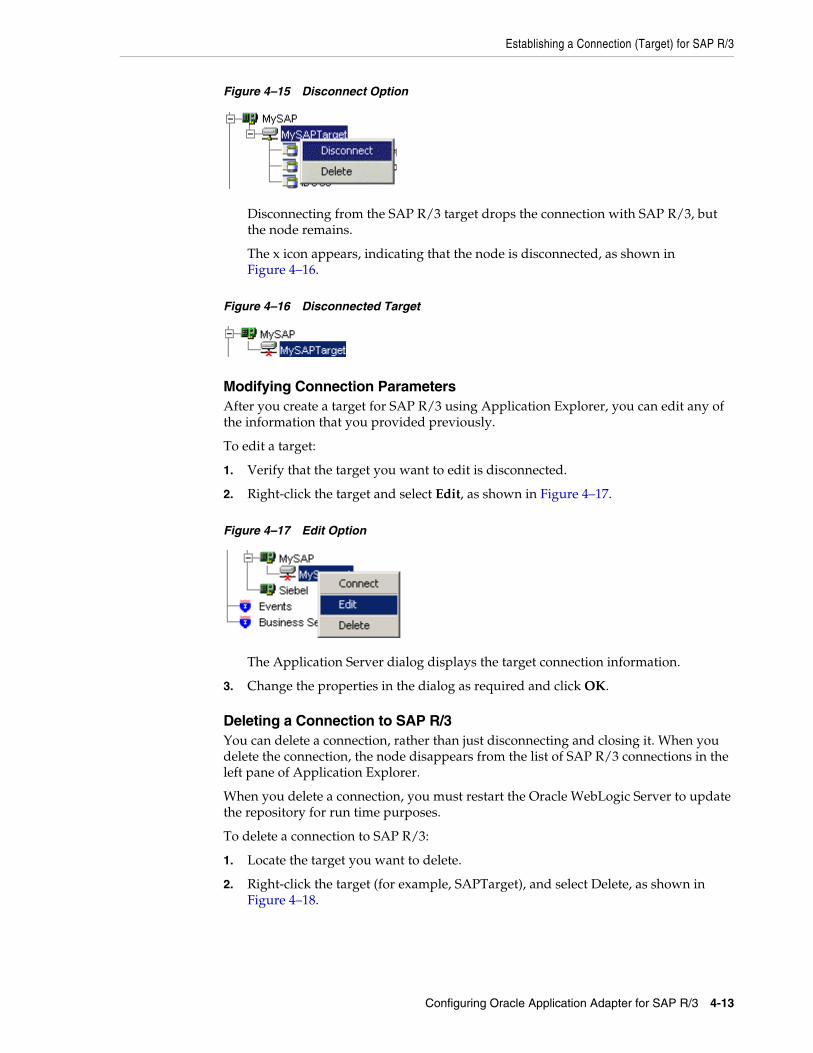
Establishing a Connection (Target) for SAP R/3
Configuring Oracle Application Adapter for SAP R/3 4-13
Figure 4–15 Disconnect Option
Disconnecting from the SAP R/3 target drops the connection with SAP R/3, but the node remains.
The x icon appears, indicating that the node is disconnected, as shown in Figure 4–16.
Figure 4–16 Disconnected Target
Modifying Connection ParametersAfter you create a target for SAP R/3 using Application Explorer, you can edit any of the information that you provided previously.
To edit a target:
1. Verify that the target you want to edit is disconnected.
2. Right-click the target and select Edit, as shown in Figure 4–17.
Figure 4–17 Edit Option
The Application Server dialog displays the target connection information.
3. Change the properties in the dialog as required and click OK.
Deleting a Connection to SAP R/3You can delete a connection, rather than just disconnecting and closing it. When you delete the connection, the node disappears from the list of SAP R/3 connections in the left pane of Application Explorer.
When you delete a connection, you must restart the Oracle WebLogic Server to update the repository for run time purposes.
To delete a connection to SAP R/3:
1. Locate the target you want to delete.
2. Right-click the target (for example, SAPTarget), and select Delete, as shown in Figure 4–18.

Viewing Application System Objects
4-14 Oracle Fusion Middleware Application Adapter for SAP R/3 (SAP JCo 3.0) User's Guide for Oracle WebLogic Server
Figure 4–18 Delete Option
The node disappears from the list of available connections.
4.5 Viewing Application System ObjectsAs you connect to SAP R/3, Application Explorer enables you to explore and browse SAP R/3 business objects that are used to support existing business processes.
4.6 Creating XML SchemasAfter you explore the SAP R/3 business function library and select an object, you can use Application Explorer to create the XML request schema and the XML response schema for that function.
To create request and response schemas for a SAP R/3 business function.
1. Connect to a SAP R/3 target as described in "Connecting to a Defined SAP R/3 Target" on page 4-12.
2. Expand the Business Object Repository node.
3. Click the icon to the left of the Financial Accounting node.
4. Scroll down and click the icon to the left of the CompanyCode business object.
5. Scroll down and select the BAPI named GetDetail.
The XML schema tabs appear on the right, as shown in Figure 4–19.
Figure 4–19 XML Schema Tabs
Note: Depending on the release or service pack installed, certain RFCs, for example, RFC_CUSTOMER_GET, may not exist in your particular SAP R/3 system. Therefore, the examples included in this documentation may not be relevant to your system. If this is the case, then you should use the examples as a general reference for adapter functionality and choose an RFC that exists within your SAP R/3 application environment.
As described in SAP Release Note 109533, SAP Function Modules (RFCs) can be delivered with different release statuses. SAP supports only RFCs that are awarded the Released for Customer status. There is no claim to the release independencies of the interfaces and the continued existence/functionality of the modules. For more information on the status of a specific function module, consult your SAP Service Marketplace.

Generating WSDL (J2CA Configurations Only)
Configuring Oracle Application Adapter for SAP R/3 4-15
6. To view the XML for each schema type, click the appropriate tab.
4.7 Generating WSDL (J2CA Configurations Only)The Web Service Definition Language (WSDL) description of a service enables you to make the service available to other services within a host server. You use Application Explorer to create both request-response (outbound) and event notification (inbound) J2CA services of the adapter.
To generate a WSDL file for request-response service:
1. After you create a schema, right-click the respective object.
The GetList menu is displayed, as shown in Figure 4–20.
Figure 4–20 Create Outbound JCA Service (Request/Response)
2. Select Create Outbound JCA Service (Request/Response).
The Export WSDL dialog is displayed, as shown in Figure 4–21.
Note: The Create Inbound JCA Service (Event) option is only available when the selected node supports events.

Creating and Testing a Web Service (BSE Configurations Only)
4-16 Oracle Fusion Middleware Application Adapter for SAP R/3 (SAP JCo 3.0) User's Guide for Oracle WebLogic Server
Figure 4–21 Export WSDL Dialog
3. Accept the default name for the file.
The .wsdl file extension is added automatically. By default, the names of WSDL files generated for request-response services end with _invoke, while those generated for event notification end with _receive.
4. Click OK.
The WSDL file is saved in the specified location.
The procedure for generating WSDL for event notification is similar to request-response. To generate WSDL for event notification, you must first create a channel for every event. For more information, see "Generating WSDL for Event Integration" on page 6-41.
4.8 Creating and Testing a Web Service (BSE Configurations Only)Using Application Explorer, you can explore the business function repository and generate Web services (also known as a business service) for the SAP R/3 functions you want to use with the adapter. The following procedure uses the SAP R/3 BAPI method called BAPI_MATERIAL_GETLIST as an example and returns a list of materials from SAP R/3.
Creating a Web ServiceTo create a Web service for a SAP R/3 business function:
Note: In a J2EE Connector Architecture (J2CA) implementation of the adapter, Web services are not available. When the adapter is deployed to use the Oracle Adapter J2CA, the Common Client Interface provides integration services using the adapter.

Creating and Testing a Web Service (BSE Configurations Only)
Configuring Oracle Application Adapter for SAP R/3 4-17
1. Connect to your SAP R/3 target and expand the Business Object Repository node.
2. Select the BAPI_MATERIAL_GETLIST method from the Business Object Repository.
3. Right-click the node from which you want to create a business service and select Create Web Service.
The Create Web Service dialog is displayed. You can add the business function as a method for a new Web service or as a method for an existing one, as shown in Figure 4–22.
Figure 4–22 Create Web Service Dialog
Perform the following steps:
a. From the Existing Service Names list, select either <new service> or an existing service.
b. If you are creating a new service, then specify a service name. This name identifies the Web service in the list of services under the Business Services node.
c. Enter a brief description for the service (optional).
4. Click Next.
The License and Method dialog is displayed.
Provide the following information:
a. In the License Name field, select one or more license codes to assign to the Web service. To make multiple selections, press the Ctrl key and click the licenses.
b. In the Method Name field, enter a descriptive name for the method.
c. In the Method Description field, enter a brief description of the method.
d. In the DTD Directory field, specify the location of the DTD you want to use.
5. Click OK.
Application Explorer switches the view to the Business Services node, and the new Web service appears in the left pane.
Testing a Web ServiceAfter a Web service is created, you can test it to ensure it functions properly. A test tool is provided for testing the Web service.

Creating and Testing a Web Service (BSE Configurations Only)
4-18 Oracle Fusion Middleware Application Adapter for SAP R/3 (SAP JCo 3.0) User's Guide for Oracle WebLogic Server
To test a Web service:
1. Click the Business Services node to access your Web services.
2. Expand the Services node.
3. Select the name of the business service you want to test.
The business service name appears as a link in the right pane.
4. In the right pane, click the named business services link.
The test option appears in a separate BSE Servlet page. If you are testing a Web service that requires XML input, then an input field is displayed.
5. Enter the appropriate input.
6. Click Invoke.
The BSE Servlet page displays the results.
Identity PropagationIf you test or run a Web service using a third party XML editor, then the user name and password values that you specify in the SOAP header must be valid and are used to connect to SAP R/3. The user name and password values that you provided for SAP R/3 during target creation using Application Explorer are overwritten for this Web service request. The following is a sample SOAP header that is included in the WSDL file for a Web service:
<SOAP-ENV:Header> <m:ibsinfo xmlns:m="urn:schemas-iwaysoftware-com:iwse"> <m:service>String</m:service> <m:method>String</m:method> <m:license>String</m:license> <m:disposition>String</m:disposition> <m:Username>String</m:Username> <m:Password>String</m:Password> <m:language>String</m:language> </m:ibsinfo></SOAP-ENV:Header>
You can remove the <m:disposition> and <m:language> tags from the SOAP header, since they are not required.
Oracle ERP Adapter WSDL Definition LimitationsThis section describes certain limitations with WSDL definitions that are generated by Oracle ERP Adapters, and provides workarounds where applicable.
Qualified/Unqualified Options
The qualified and unqualified options are not enforced by the Oracle ERP Adapter when WSDL definition are generated. For example:
1. Export a WSDL with the qualified option specified.
2. Create a Web service based on this WSDL.
3. Send XML data that contains unqualified elements to this Web service.
A correct response document is received.
Namespaces
Namespaces that are defined in the generated WSDL definition are not enforced by the Oracle ERP Adapter. For example:
Configuring an Event Adapter
Configuring Oracle Application Adapter for SAP R/3 4-19
1. Create a Web service based on a generated WSDL.
2. Send XML data where all namespaces have been removed to this Web service.
A correct response document is received.
Unchecked Data
The Oracle ERP Adapter does not verify if XML data conforms to the generated WSDL definition. For demonstration purposes only, the following example uses SAP R/3:
1. Create a Web service for the RFC_SYSTEM_INFO function module.
2. Invoke this Web service (RFC_SYSTEM_INFO) with XML data pertaining to BAPI_COMPANYCODE_GETLIST.
A response document is received with data for BAPI_COMPANYCODE_GETLIST.
This behavior should be taken into consideration when designing an application using Oracle ERP Adapters. As a best practice, always validate the XML data that is received according to the WSDL definition before a Web service is invoked. Otherwise, all functions can be exposed on a system (for example, SAP R/3) if only one function is called. In this example, only the RFC_SYSTEM_INFO function module was called, but an end-user could have invoked any function on SAP R/3 using this function. Only a valid XML document that is recognized by the Oracle ERP Adapter for a given function is required.
4.9 Configuring an Event AdapterEvents are generated by activity in a database or in an application system. You can use events to trigger an action in your application. For example, an update to a database can reflect an update to customer information. If your application must perform when this happens, then your application is a consumer of this event.
After you create a connection to your application system, you can add events using Application Explorer. To create an event, you must create a channel.
A channel represents configured connections to particular instances of back-end systems. For more information, see "Creating and Editing a Channel" on page 4-19.
4.9.1 Creating and Editing a ChannelThe following procedure describes how to create a channel for your event. All defined event ports must be associated with a channel.
When you create, modify, or delete a channel, you must restart the Oracle WebLogic Server to recognize the change and update the repository for run time purposes.
Note: If you are using a J2CA configuration, then you must create a new channel for every different event object and select this channel when creating an inbound service. Creating a channel is required for J2CA configurations only. In addition, each channel must be associated with a unique SAP R/3 Program ID. For example, if you are working with MATMAS and DEBMAS, then two separate channels are required for each object and two unique SAP R/3 Program IDs.

Configuring an Event Adapter
4-20 Oracle Fusion Middleware Application Adapter for SAP R/3 (SAP JCo 3.0) User's Guide for Oracle WebLogic Server
Events are not applicable when using a BSE configuration. You can configure events using a J2CA configuration only.
Creating and updating a channel requires you to restart the application server. The application server must also be restarted after you create a channel and generate an inbound WSDL. In addition, ensure to close Application Explorer before you restart the application server.
Creating a ChannelTo create a channel:
1. Click the Events node, as shown in Figure 4–23.
Figure 4–23 Events Node
2. Expand the MySAP node.
The ports and channels nodes appear in the left pane.
3. Right-click Channels and select Add Channel.
The Add Channel dialog is displayed, as shown in Figure 4–24.
Note: Channels can be configured and started only on the system where the Oracle Application Adapter for SAP R/3 is installed. Configuring and starting a channel for a remote host is not supported.

Configuring an Event Adapter
Configuring Oracle Application Adapter for SAP R/3 4-21
Figure 4–24 Add Channel Dialog
Perform the following steps:
a. Enter a name for the channel, for example, TEST_CHANNEL.
b. Enter a brief description.
c. From the Protocol list, select Application Server - mySAP or Message Server - mySAP.
4. Click Next.
The Message Server dialog is displayed. The following tabs are available:
■ User (Required)
■ System (Required)
■ Security
■ Advanced
5. For the User tab, enter the appropriate information for your SAP R/3 channel based on the information in the following table.
6. For the System tab, enter the appropriate information for your SAP R/3 channel based on the information in the following table.
Table 4–5 User Tab Parameters
Target Parameter Description
Client The client number defined for the SAP application for client communications.
User A valid user ID for the SAP application.
Password A valid password for the SAP application.
Authentication Mode The authentication mode you want to use when connecting to your SAP R/3 system. By default, Password is selected from the drop-down list.
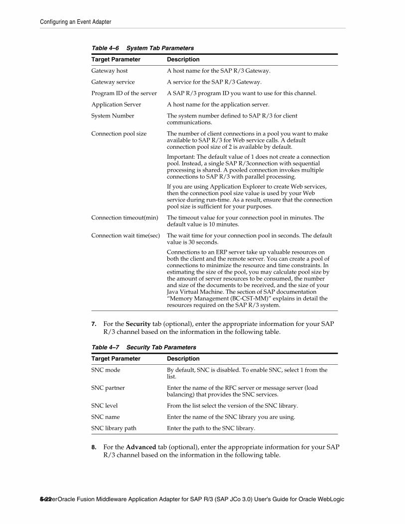
Configuring an Event Adapter
4-22 Oracle Fusion Middleware Application Adapter for SAP R/3 (SAP JCo 3.0) User's Guide for Oracle WebLogic Server
7. For the Security tab (optional), enter the appropriate information for your SAP R/3 channel based on the information in the following table.
8. For the Advanced tab (optional), enter the appropriate information for your SAP R/3 channel based on the information in the following table.
Table 4–6 System Tab Parameters
Target Parameter Description
Gateway host A host name for the SAP R/3 Gateway.
Gateway service A service for the SAP R/3 Gateway.
Program ID of the server A SAP R/3 program ID you want to use for this channel.
Application Server A host name for the application server.
System Number The system number defined to SAP R/3 for client communications.
Connection pool size The number of client connections in a pool you want to make available to SAP R/3 for Web service calls. A default connection pool size of 2 is available by default.
Important: The default value of 1 does not create a connection pool. Instead, a single SAP R/3connection with sequential processing is shared. A pooled connection invokes multiple connections to SAP R/3 with parallel processing.
If you are using Application Explorer to create Web services, then the connection pool size value is used by your Web service during run-time. As a result, ensure that the connection pool size is sufficient for your purposes.
Connection timeout(min) The timeout value for your connection pool in minutes. The default value is 10 minutes.
Connection wait time(sec) The wait time for your connection pool in seconds. The default value is 30 seconds.
Connections to an ERP server take up valuable resources on both the client and the remote server. You can create a pool of connections to minimize the resource and time constraints. In estimating the size of the pool, you may calculate pool size by the amount of server resources to be consumed, the number and size of the documents to be received, and the size of your Java Virtual Machine. The section of SAP documentation “Memory Management (BC-CST-MM)” explains in detail the resources required on the SAP R/3 system.
Table 4–7 Security Tab Parameters
Target Parameter Description
SNC mode By default, SNC is disabled. To enable SNC, select 1 from the list.
SNC partner Enter the name of the RFC server or message server (load balancing) that provides the SNC services.
SNC level From the list select the version of the SNC library.
SNC name Enter the name of the SNC library you are using.
SNC library path Enter the path to the SNC library.

Configuring an Event Adapter
Configuring Oracle Application Adapter for SAP R/3 4-23
9. Click OK.
The channel appears under the channels node in the left pane, as shown in Figure 4–25.
Figure 4–25 MySAP_Channel
An X over the icon indicates that the channel is currently disconnected. You must start the channel to activate your event configuration.
Table 4–8 Advanced Tab Parameters
Target Parameter Description
IDOC Format Select an IDOC type from the list:
■ XML (default)
■ XML-CDATA-ENVELOPED
■ NATIVE IDOC
IDOC release The IDOC versioning you want to use for your connection.
IDOC release provider The IDOC release provider for your connection. Select IDOC DOCREL field (default), SAP release, or user input from the drop-down list.
IDOC(flat) encoding The type of encoding for IDOC processing.
SAP trace Select this option to enable SAP traces.
The SAP traces are stored in the following locations during design time and run time:
Design Time:
<ADAPTER_HOME>\soa\thirdparty\ApplicationAdapters\tools\iwae\bin
Run Time:
<ADAPTER_HOME>\user_projects\domains\base_domain
The file name formats that are used for the SAP traces are as follows (for design time and run time):
■ rfc02664_04332.trc
■ JCO100226_043846994.trc
Trace level Indicates the level of detail in the SAP traces. Select a value that ranges from 0 through 10 from the list.
Thread count The number of open threads. By default, three threads are specified.
Processing Mode Select the type of synchronous processing from the list. Possible values include REQUEST and REQUEST_RESPONSE.

Configuring an Event Adapter
4-24 Oracle Fusion Middleware Application Adapter for SAP R/3 (SAP JCo 3.0) User's Guide for Oracle WebLogic Server
10. Right-click the channels node and select Start.
The channel you created becomes active, as shown in Figure 4–26.
Figure 4–26 Active MySAP_Channel
The X over the icon disappears.
11. To stop the channel, right-click the connected channel node and select Stop.
The channel becomes inactive and an X appears over the icon.
Editing a ChannelTo edit a channel:
1. In the left pane, locate the channel you want to edit.
2. Right-click the channel and select Edit.
The Edit Channel pane is displayed.
3. Make the required changes to the channel configuration and click Finish.
When you edit a channel, you must restart the Oracle WebLogic Server to recognize the change and update the repository for run time purposes.
Deleting a ChannelTo delete a channel:
1. In the left pane, locate the channel you want to delete.
2. Right-click the channel and select Delete.
The channel disappears from the list in the left pane.
When you delete a channel, you must restart the Oracle WebLogic Server to recognize the change and update the repository for run time purposes.
4.9.2 Schema ValidationRoot validation, namespace validation, and schema validation for inbound processing (events) are supported for the Oracle Application Adapter for SAP R/3 with BPEL 11.1.1.
Note: If you are planning to integrate Oracle Application Adapter for SAP R/3 with BPEL inbound or Mediator inbound process components, then do not start the channel. The channel is managed by the run-time server after the BPEL or Mediator process component is deployed. If you start the channel from Application Explorer for testing and debugging purposes, then stop it before run-time (when working with BPEL or Mediator process components).

Configuring an Event Adapter
Configuring Oracle Application Adapter for SAP R/3 4-25
To validate inbound processing using the Oracle Application Adapter for SAP R/3, perform the following steps. This procedure uses MATMAS (Material Master) as an example for inbound processing.
1. Start Application Explorer.
2. Connect to the MySAP target.
3. Expand the IDOCs node.
4. Verify that you created a channel for the MySAP adapter.
5. Select and expand the MATMAS – Material Master node.
6. Right-click MATMAS01 select Create Inbound JCA Service (event).
The Export WSDL dialog opens and includes three check boxes for Root, Namespace, and Schema validation, as shown in Figure 4–27.
Figure 4–27 Export WSDL Dialog
■ Selection of multiple validation options is allowed.
■ Root validation is used to validate the root element in the inbound XML document.
■ Namespace validation is used to validate the namespace in the inbound XML document.
■ Schema validation is used to validate the inbound XML document with the schema in the WSDL document.
■ During run time, validation is processed based on the validation options that are selected.
■ If multiple validation options are selected, then during run time if the first validation option fails, the remaining validation options are not processed.

Configuring an Event Adapter
4-26 Oracle Fusion Middleware Application Adapter for SAP R/3 (SAP JCo 3.0) User's Guide for Oracle WebLogic Server
■ Root and namespace validations are considered modest levels of validation. Schema validation is a stricter validation level.
■ It is recommended to use root and namespace validation options, unless the root element and namespace are different between the IDOCs in the SAP environment.
7. Generate the WSDL document and create the BPEL process.
8. Trigger the transactions (IDOCs) from the SAP GUI.
Inbound transactions that fail for the validation are shown in the SAP Transaction Monitor (SM58).
The status text field shows "java.lang.exception" for the documents that have failed the validation process.

5
Oracle WebLogic Server Deployment and Integration 5-1
5 Oracle WebLogic Server Deployment andIntegration
This chapter describes Oracle WebLogic Server (OracleWLS) deployment and integration with Oracle Application Adapter for SAP R/3. It contains the following topics:
■ Section 5.1, "Adapter Integration with Oracle WebLogic Server"
■ Section 5.2, "Deployment of Adapter"
■ Section 5.3, "Updating Adapter Configuration"
5.1 Adapter Integration with Oracle WebLogic ServerOracle Application Adapter for SAP R/3 is deployed within an OracleWLS container during installation. All client applications run within the OracleWLS environment. In J2CA deployment, the Common Client Interface (CCI) integrates an OracleWLS client application with a resource adapter.
5.2 Deployment of AdapterFigure 5–1 shows deployment of the J2CA Connector to the Oracle Application Server. In a run-time service scenario, an Enterprise Java Bean, servlet, or Java program client makes CCI calls to J2CA resource adapters. The adapters process the calls as requests and send them to the EIS. The EIS response is then sent back to the client.
See Also:
■ Oracle WebLogic Server Adapter Concepts
See Also:
■ Oracle WebLogic Server Adapter Concepts

Updating Adapter Configuration
5-2 Oracle Fusion Middleware Application Adapter for SAP R/3 (SAP JCo 3.0) User's Guide for Oracle WebLogic Server
Figure 5–1 Oracle Application Server J2CA Architecture
5.3 Updating Adapter ConfigurationDuring the J2CA deployment of Oracle Application Adapter for SAP R/3, OracleWLS generates a deployment descriptor called ra.xml, located in:
<ADAPTER_HOME>\soa\thirdparty\ApplicationAdapters\iwafjca.rar\META-INF
The OracleWLS deployment descriptor is located in the directory specified above.
Creating a Managed Connector Factory ObjectThe ra.xml descriptor provides OracleWLS-specific deployment information for resource adapters. For example, the jca_sample configuration in Application Explorer is represented in the ra.xml file as follows:
<?xml version="1.0" encoding="UTF-8"?><!DOCTYPE connector PUBLIC '-//Sun Microsystems, Inc.//DTD Connector 1.0//EN' 'http://java.sun.com/dtd/connector_1_0.dtd'><connector> <display-name>IWAFJCA10</display-name> <vendor-name>IWAY Software</vendor-name>
See Also:
■ Oracle WebLogic Server Adapter Concepts
Note: Multiple managed connection factories are supported only for outbound processing (services).
Oracle Application Server
JCA Connector
JCAContainer
Adapter Framework
OracleAS AdapterApplication Explorer(Design Time)
EJB orServletContainer
CommonClient
Interface
EnterpriseJavaBeans
Servlet
SAP
File Repository(Default)
1
1 Use either the default file repository or an Oracle database as your repository.
OracleDatabase
Adapter

Updating Adapter Configuration
Oracle WebLogic Server Deployment and Integration 5-3
<spec-version>1.0</spec-version> <eis-type>IWAF</eis-type> <version>1.0</version> <license> <license-required>false</license-required> </license> <resourceadapter> <managedconnectionfactory-class>com.ibi.afjca.spi.IWAFManagedConnectionFactory</managedconnectionfactory-class> <connectionfactory-interface>javax.resource.cci.ConnectionFactory</connectionfactory-interface> <connectionfactory-impl-class>com.ibi.afjca.cci.IWAFConnectionFactory</connectionfactory-impl-class> <connection-interface>javax.resource.cci.Connection</connection-interface> <connection-impl-class>com.ibi.afjca.cci.IWAFConnection</connection-impl-class> <transaction-support>NoTransaction</transaction-support> <config-property> <config-property-name>AdapterName</config-property-name> <config-property-type>java.lang.String</config-property-type> <config-property-value></config-property-value> </config-property> <config-property> <config-property-name>Config</config-property-name> <config-property-type>java.lang.String</config-property-type> <config-property-value></config-property-value> </config-property> <config-property> <config-property-name>IWayHome</config-property-name> <config-property-type>java.lang.String</config-property-type> <config-property-value>C:\oracle\Middleware\Oracle_SOA1\soa\thirdparty\ApplicationAdapters</config-property-value> </config-property> <config-property> <config-property-name>IWayConfig</config-property-name> <config-property-type>java.lang.String</config-property-type> <config-property-value>jca_sample</config-property-value> </config-property> <config-property> <config-property-name>IWayRepoDriver</config-property-name> <config-property-type>java.lang.String</config-property-type> <config-property-value></config-property-value> </config-property> <config-property> <config-property-name>IWayRepoURL</config-property-name> <config-property-type>java.lang.String</config-property-type> <config-property-value></config-property-value> </config-property> <config-property> <config-property-name>IWayRepoUser</config-property-name> <config-property-type>java.lang.String</config-property-type> <config-property-value></config-property-value> </config-property> <config-property> <config-property-name>IWayRepoPassword</config-property-name> <config-property-type>java.lang.String</config-property-type> <config-property-value></config-property-value>

Updating Adapter Configuration
5-4 Oracle Fusion Middleware Application Adapter for SAP R/3 (SAP JCo 3.0) User's Guide for Oracle WebLogic Server
</config-property> <config-property> <config-property-name>LogLevel</config-property-name> <config-property-type>java.lang.String</config-property-type> <config-property-value>DEBUG</config-property-value> </config-property> <authentication-mechanism> <authentication-mechanism-type>BasicPassword</authentication-mechanism-type> <credential-interface>javax.resource.spi.security.PasswordCredential</credential-interface> </authentication-mechanism> <reauthentication-support>true</reauthentication-support> </resourceadapter></connector>
The parameters defined in the ra.xml file are described in the following table:
Creating Multiple Managed Connector Factory ObjectsTo establish multiple managed connector factory objects, you must edit the weblogic-ra.xml file and add more <connection-instance> nodes. This file is located in:
<ADAPTER_HOME>\soa\thirdparty\ApplicationAdapters\iwafjca.rar\META-INF
For example, the first jca_configuration in Application Explorer is represented in the weblogic-ra.xml file as follows:
<?xml version="1.0"?> <weblogic-connector xmlns="http://www.bea.com/ns/weblogic/90"> <enable-access-outside-app>true</enable-access-outside-app> <enable-global-access-to-classes>true</enable-global-access-to-classes> <outbound-resource-adapter> <default-connection-properties> <pool-params> <initial-capacity>0</initial-capacity> </pool-params>
Parameter Name Description
IWayHome The base installation directory for the OracleWLS packaged application adapter.
IWayConfig The adapter configuration name as defined in Application Explorer. For example, Oracle Application Adapter for SAP R/3 has a preconfigured jca_sample configuration in Application Explorer.
IWayRepoURL The URL to use when opening a connection to the database. This is necessary only when using an Oracle database as the repository.
IWayRepoUser User name to use when connecting to the database. This is necessary only when using an Oracle database as the repository.
IWayRepoPassword Password. If provided, then it overwrites the configuration. This is necessary only when using an Oracle database as the repository.
loglevel It overwrites the level set by the ManagedConnectorFactory property.

Updating Adapter Configuration
Oracle WebLogic Server Deployment and Integration 5-5
<transaction-support>LocalTransaction</transaction-support> </default-connection-properties> <connection-definition-group> <connection-factory-interface>javax.resource.cci.ConnectionFactory</connection-factory-interface> <connection-instance> <jndi-name>eis/OracleJCAAdapter/DefaultConnection</jndi-name> </connection-instance> </connection-definition-group> </outbound-resource-adapter></weblogic-connector>
To create multiple managed connector factory objects, you must add new <connection-instance> nodes in the file. For example:
<?xml version="1.0"?> <weblogic-connector xmlns="http://www.bea.com/ns/weblogic/90">
<enable-access-outside-app>true</enable-access-outside-app> <enable-global-access-to-classes>true</enable-global-access-to-classes> <outbound-resource-adapter> <default-connection-properties> <pool-params> <initial-capacity>0</initial-capacity> </pool-params> <transaction-support>LocalTransaction</transaction-support> </default-connection-properties> <connection-definition-group> <connection-factory-interface>javax.resource.cci.ConnectionFactory</connection-factory-interface> <connection-instance> <jndi-name>eis/OracleJCAAdapter/DefaultConnection</jndi-name> </connection-instance> <connection-instance> <jndi-name>eis/OracleJCAAdapter/DefaultConnection1</jndi-name> <connection-properties> <properties> <property><name>IWayHome</name><value>C:\oracle\Middleware\Oracle_SOA1\soa\thirdparty\ApplicationAdapters</value> </property> <property> <name>IWayConfig</name> <value>jca_sample2</value> </property> <property> <name>IWayRepoURL</name> <value></value> </property> <property> <name>IWayRepoUser</name> <value></value> </property> <property> <name>IWayRepoPassword</name> <value></value> </property> <property>
Updating Adapter Configuration
5-6 Oracle Fusion Middleware Application Adapter for SAP R/3 (SAP JCo 3.0) User's Guide for Oracle WebLogic Server
<name>LogLevel</name> <value>Debug</value> </property> </properties> </connection-properties> </connection-instance> </connection-definition-group> </outbound-resource-adapter></weblogic-connector>
If you do not specify a <property> element in the <connection-instance> section, then the value is taken from the ra.xml file. You can specify the default properties in the ra.xml file and then override them as required in the weblogic-ra.xml file. In addition, note that the J2CA configuration (for example, jca_sample2) must be created in Application Explorer.
Modifying WSDL Files for Additional Connection Factory ValuesApplication Explorer generates the J2CA properties file using the default connection factory name eis/OracleJCAAdapter/DefaultConnection. If you created additional connection factories, then the WSDLs generated for the additional configuration and connection factory should be changed to reflect the location field of the jca:address section in the J2CA properties file. The default J2CA properties file for the Oracle Application Adapter for SAP R/3 with a configuration of isdsrv2_conn2 is shown in the following example.
Notice that the J2CA properties file has the following default connection factory: eis/OracleJCAAdapter/DefaultConnection
<jca:address location="eis/OracleJCAAdapter/DefaultConnection" ConnectionSpec="com.ibi.afjca.cci.IWAFConnectionSpec" cs.AdapterName="MySAP" cs.Config="isdsrv2_conn2" UIConnectionName="Connection1"/>
The connection factory value must be changed to the following: eis/OracleJCAAdapter/DefaultConnection1
For example:
<jca:address location="eis/OracleJCAAdapter/DefaultConnection1" ConnectionSpec="com.ibi.afjca.cci.IWAFConnectionSpec" cs.AdapterName="MySAP" cs.Config="isdsrv2_conn2" UIConnectionName="Connection1"/>
Note that only the value for the location field in the jca:address section should be modified. Do not modify any other field or section.
Note: When you modify the ra.xml and weblogic-ra.xml files, the application server must be restarted. If the application server is running, then stop the application server and then restart it.
In addition, the iwafjca.rar file must be redeployed in the Oracle WebLogic Administration Console to activate these changes.
6
Integration With BPEL Service Components in the Oracle SOA Suite 6-1
6 Integration With BPEL Service Componentsin the Oracle SOA Suite
Oracle Application Adapter for SAP R/3 integrates seamlessly with Business Process Execution Language (BPEL) Process Manager to facilitate Web service integration. Oracle BPEL Process Manager is based on the Service-Oriented Architecture (SOA). It consumes adapter services exposed as Web Service Definition Language (WSDL) documents.
This chapter contains the following topics:
■ Section 6.1, "Overview"
■ Section 6.2, "Deployment of Adapter"
■ Section 6.3, "Configuring a New Application Server Connection"
■ Section 6.4, "Designing an Outbound BPEL Process for Service Integration"
■ Section 6.5, "Designing an Inbound BPEL Process for Event Integration"
6.1 OverviewTo integrate with Oracle BPEL Process Manager, Oracle Application Adapter for SAP R/3 must be deployed in the same WLS container as Oracle BPEL Process Manager. The underlying adapter services must be exposed as WSDL files, which are generated during design time in Oracle Adapter Application Explorer (Application Explorer) for both request-response (outbound) and event notification (inbound) services of the adapter. For more information, see "Generating WSDL (J2CA Configurations Only)" on page 4-15.
The generated WSDL files are used to design the appropriate BPEL processes for inbound or outbound adapter services. A completed BPEL process must be successfully compiled in JDeveloper and deployed to a BPEL server. Upon deployment to the BPEL server, every newly built process is automatically deployed to the Oracle Enterprise Manager console, where you run, monitor, and administer BPEL processes, and listen to adapter events.
6.2 Deployment of AdapterDuring installation, Oracle Application Adapter for SAP R/3 is deployed as a J2CA 1.0 resource adapter within the WLS container. The adapter must be deployed in the same WLS container as Oracle BPEL Process Manager.

Configuring a New Application Server Connection
6-2 Oracle Fusion Middleware Application Adapter for SAP R/3 (SAP JCo 3.0) User's Guide for Oracle WebLogic Server
6.3 Configuring a New Application Server ConnectionTo configure a new Application Server connection in Oracle JDeveloper:
1. Open Oracle JDeveloper on your system.
2. From the menu bar, click View and select Application Server Navigator, as shown in Figure 6–1.
Figure 6–1 Application Server Navigator
The Application Server tab is displayed, as shown in Figure 6–2.
Figure 6–2 Application Server Tab
3. Right-click Application Servers and select New Application Server.
The Create Application Server Connection Wizard is displayed, as shown in Figure 6–3.

Configuring a New Application Server Connection
Integration With BPEL Service Components in the Oracle SOA Suite 6-3
Figure 6–3 Create Application Server Connection Wizard
4. Accept the default selection (Standalone Server) and click Next.
The Name and Type page is displayed, as shown in Figure 6–4.
Figure 6–4 Name and Type Page

Configuring a New Application Server Connection
6-4 Oracle Fusion Middleware Application Adapter for SAP R/3 (SAP JCo 3.0) User's Guide for Oracle WebLogic Server
5. Specify a new name for the Application Server connection and click Next.
The Authentication page is displayed, as shown in Figure 6–5.
Figure 6–5 Authentication Page
6. Specify a valid user name (for example, weblogic) and a password (for example, welcome1) for your new connection.
7. Click Next.
The Configuration page is displayed, as shown in Figure 6–6.
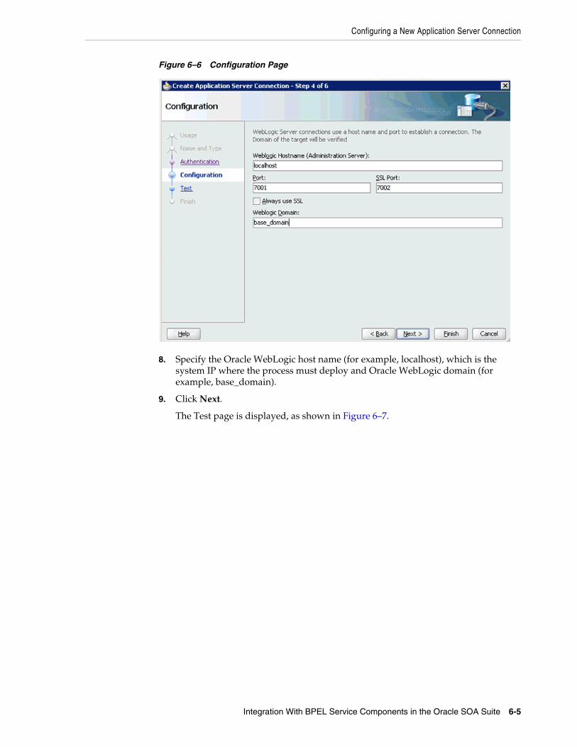
Configuring a New Application Server Connection
Integration With BPEL Service Components in the Oracle SOA Suite 6-5
Figure 6–6 Configuration Page
8. Specify the Oracle WebLogic host name (for example, localhost), which is the system IP where the process must deploy and Oracle WebLogic domain (for example, base_domain).
9. Click Next.
The Test page is displayed, as shown in Figure 6–7.

Configuring a New Application Server Connection
6-6 Oracle Fusion Middleware Application Adapter for SAP R/3 (SAP JCo 3.0) User's Guide for Oracle WebLogic Server
Figure 6–7 Test Page
10. Click Test Connection.
11. Make sure that the test status is successful.
12. Click Next.
The Finish page is displayed, as shown in Figure 6–8.

Designing an Outbound BPEL Process for Service Integration
Integration With BPEL Service Components in the Oracle SOA Suite 6-7
Figure 6–8 Finish Page
13. Click Finish.
The new Application Server connection is listed in the left pane (Application Server tab), as shown in Figure 6–9.
Figure 6–9 New Application Server Connection
6.4 Designing an Outbound BPEL Process for Service IntegrationThe following tools are required to complete your outbound design-time configuration:
■ Oracle Adapter Application Explorer (Application Explorer)
■ Oracle JDeveloper BPEL Designer (JDeveloper) or Eclipse

Designing an Outbound BPEL Process for Service Integration
6-8 Oracle Fusion Middleware Application Adapter for SAP R/3 (SAP JCo 3.0) User's Guide for Oracle WebLogic Server
Before you design a BPEL process, you must generate the respective WSDL file using Application Explorer. For more information, see "Generating WSDL for Request/Response Service" on page 6-8.
6.4.1 Generating WSDL for Request/Response ServicePerform the following steps to generate a WSDL for request/response service:
1. Start Application Explorer and connect to a defined MySAP target (a J2CA configuration).
For more information on defining a target and connecting to SAP R/3, see "Defining a Target to SAP R/3" on page 4-5.
2. Expand the MySAP target to which you are connected.
3. Expand Remote Function Modules, Financial Accounting, 0002 -- Company Code Business Object, and then select BAPI_COMPANYCODE_GETDETAIL, as shown in Figure 6–10.
Figure 6–10 Connected MySAP_Target
4. Right-click the BAPI_COMPANYCODE_GETDETAIL node.
A menu is displayed, as shown in Figure 6–11.
Note: The examples in this chapter demonstrate the use of JDeveloper.

Designing an Outbound BPEL Process for Service Integration
Integration With BPEL Service Components in the Oracle SOA Suite 6-9
Figure 6–11 BAPI_COMPANYCODE_GETDETAIL Node
5. Click Create Outbound JCA Service (Request/Response).
The Export WSDL dialog is displayed, as shown in Figure 6–12.
Figure 6–12 Export WSDL Dialog
6. Click OK.
You can now create an empty composite for SOA, which is the first step that is required to define a BPEL outbound process in JDeveloper.
6.4.2 Creating an Empty Composite for SOAPerform the following steps to create an empty composite for SOA:
1. Create a new SOA application.

Designing an Outbound BPEL Process for Service Integration
6-10 Oracle Fusion Middleware Application Adapter for SAP R/3 (SAP JCo 3.0) User's Guide for Oracle WebLogic Server
2. Enter a name for the new SOA Application and click Next, as shown in Figure 6–13.
Figure 6–13 Name Your Application Page
The Name your project page is displayed, as shown in Figure 6–14.

Designing an Outbound BPEL Process for Service Integration
Integration With BPEL Service Components in the Oracle SOA Suite 6-11
Figure 6–14 Name Your Project Page
3. Enter a project name (for example, CompanyCode_GD) and click Next.
The Configure SOA settings page is displayed, as shown in Figure 6–15.
Figure 6–15 Configure SOA Settings Page

Designing an Outbound BPEL Process for Service Integration
6-12 Oracle Fusion Middleware Application Adapter for SAP R/3 (SAP JCo 3.0) User's Guide for Oracle WebLogic Server
4. From the Composite Template list, select Empty Composite and click Finish.
6.4.3 Defining a BPEL Outbound ProcessThis section describes how to define a BPEL outbound process, which consists of the following stages:
1. Configuring a Third Party Adapter Service Component
2. Configuring an Outbound BPEL Process Component
Configuring a Third Party Adapter Service ComponentPerform the following steps to create a third party adapter service component:
1. Drag and drop the Third Party Adapter component from the Service Adapters pane to the External References pane, as shown in Figure 6–16.
Figure 6–16 Third Party Adapter Component
The Create Third Party Adapter Service dialog is displayed, as shown in Figure 6–17.

Designing an Outbound BPEL Process for Service Integration
Integration With BPEL Service Components in the Oracle SOA Suite 6-13
Figure 6–17 Create Third Party Adapter Service Dialog
2. Enter a name for the third party adapter service.
3. Ensure that Reference is selected from the Type list (default).
4. Click the Find existing WSDLs icon, which is located to the right of the WSDL URL field.
The SOA Resource Browser dialog is displayed, as shown in Figure 6–18.

Designing an Outbound BPEL Process for Service Integration
6-14 Oracle Fusion Middleware Application Adapter for SAP R/3 (SAP JCo 3.0) User's Guide for Oracle WebLogic Server
Figure 6–18 SOA Resource Browser Dialog
5. Browse and select an outbound WSDL file from the following directory:
<ADAPTER_HOME>\soa\thirdparty\ApplicationAdapters\wsdls
6. Click OK.
The Localize Files dialog is displayed, as shown in Figure 6–19.

Designing an Outbound BPEL Process for Service Integration
Integration With BPEL Service Components in the Oracle SOA Suite 6-15
Figure 6–19 Localize Files Dialog
7. Click OK.
The outbound WSDL file and associated request and response XML schema files (.xsd) are imported to the project folder that has been created.
You are returned to the Create Third Party Adapter Service dialog, as shown in Figure 6–20.
Figure 6–20 Create Third Party Adapter Service Dialog
8. Click the Find JCA file icon, which is located to the right of the JCA File field.
The SOA Resource Browser dialog is displayed, as shown in Figure 6–21.
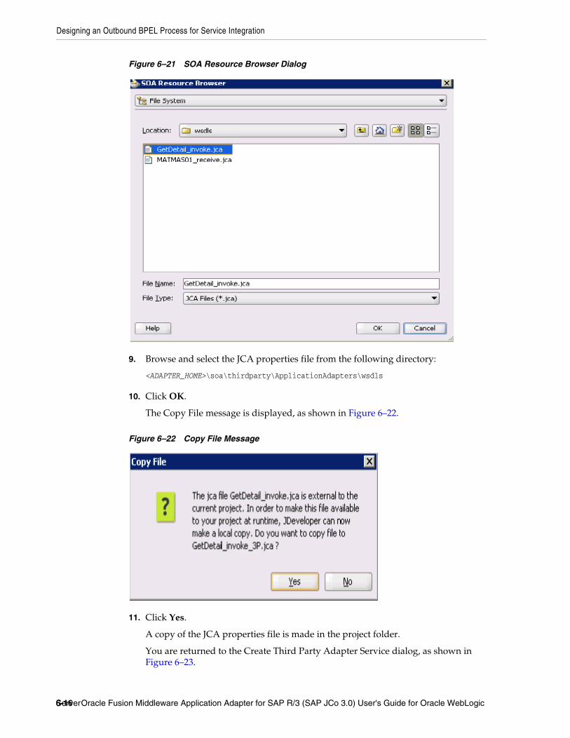
Designing an Outbound BPEL Process for Service Integration
6-16 Oracle Fusion Middleware Application Adapter for SAP R/3 (SAP JCo 3.0) User's Guide for Oracle WebLogic Server
Figure 6–21 SOA Resource Browser Dialog
9. Browse and select the JCA properties file from the following directory:
<ADAPTER_HOME>\soa\thirdparty\ApplicationAdapters\wsdls
10. Click OK.
The Copy File message is displayed, as shown in Figure 6–22.
Figure 6–22 Copy File Message
11. Click Yes.
A copy of the JCA properties file is made in the project folder.
You are returned to the Create Third Party Adapter Service dialog, as shown in Figure 6–23.

Designing an Outbound BPEL Process for Service Integration
Integration With BPEL Service Components in the Oracle SOA Suite 6-17
Figure 6–23 Create Third Party Adapter Service Dialog
12. Click OK.
The third party adapter service component (GetDetail) is created and displayed in the External References pane, as shown in Figure 6–24.

Designing an Outbound BPEL Process for Service Integration
6-18 Oracle Fusion Middleware Application Adapter for SAP R/3 (SAP JCo 3.0) User's Guide for Oracle WebLogic Server
Figure 6–24 Third Party Adapter Service Component
You are now ready to configure an outbound BPEL process component.
Configuring an Outbound BPEL Process ComponentPerform the following steps to configure an outbound BPEL process component:
1. Drag and drop the BPEL Process component from the Service Components pane to the Components pane, as shown in Figure 6–25.
Figure 6–25 BPEL Process Component

Designing an Outbound BPEL Process for Service Integration
Integration With BPEL Service Components in the Oracle SOA Suite 6-19
The Create BPEL Process dialog is displayed, as shown in Figure 6–26.
Figure 6–26 Create BPEL Process Dialog
2. In the Name field, enter a name to identify the new outbound BPEL process component (for example, cc_getdetail).
3. From the Template list, select Synchronous BPEL Process.
4. Click the Browse icon, which is located to the right of the Input field to select the associated XML request schema file.
The Type Chooser dialog is displayed, as shown in Figure 6–27.
Figure 6–27 Type Chooser Dialog

Designing an Outbound BPEL Process for Service Integration
6-20 Oracle Fusion Middleware Application Adapter for SAP R/3 (SAP JCo 3.0) User's Guide for Oracle WebLogic Server
5. Expand Project Schema Files, GetDetail_invoke_request.xsd, and select CompanyCode.GetDetail.
6. Click OK.
You are returned to the Create BPEL Process dialog, as shown in Figure 6–28.
Figure 6–28 Create BPEL Process Dialog
7. Click the Browse icon, which is located to the right of the Output field to select the associated XML response schema file.
The Type Chooser dialog is displayed, as shown in Figure 6–29.
Figure 6–29 Type Chooser Dialog

Designing an Outbound BPEL Process for Service Integration
Integration With BPEL Service Components in the Oracle SOA Suite 6-21
8. Expand Project Schema Files, GetDetail_invoke_response.xsd, and select CompanyCode.GetDetailResponse.
9. Click OK.
You are returned to the Create BPEL Process dialog, as shown in Figure 6–30.
Figure 6–30 Create BPEL Process Dialog
10. Click OK.
11. Create a connection between the outbound BPEL process component (cc_ getdetail) and the third party adapter service component (GetDetail), as shown in Figure 6–31.

Designing an Outbound BPEL Process for Service Integration
6-22 Oracle Fusion Middleware Application Adapter for SAP R/3 (SAP JCo 3.0) User's Guide for Oracle WebLogic Server
Figure 6–31 Created Connection
12. Double-click the outbound BPEL process component (cc_ getdetail) in the Components pane, as shown in Figure 6–32.
Figure 6–32 Outbound BPEL Process Component

Designing an Outbound BPEL Process for Service Integration
Integration With BPEL Service Components in the Oracle SOA Suite 6-23
13. Drag and drop the Invoke activity component to the Components pane and place it between the receiveInput activity component and the replyOutput activity component, as shown in Figure 6–33.
Figure 6–33 Invoke Activity Component
14. Create a connection between the new Invoke activity component (Invoke_1) and the third party adapter service component (GetDetail), as shown in Figure 6–34.

Designing an Outbound BPEL Process for Service Integration
6-24 Oracle Fusion Middleware Application Adapter for SAP R/3 (SAP JCo 3.0) User's Guide for Oracle WebLogic Server
Figure 6–34 Created Connection
15. Double-click the new Invoke activity component (Invoke_1).
The Edit Invoke dialog is displayed, as shown in Figure 6–35.

Designing an Outbound BPEL Process for Service Integration
Integration With BPEL Service Components in the Oracle SOA Suite 6-25
Figure 6–35 Edit Invoke Dialog
16. Click the Plus sign icon, which is located to the right of the Input field to configure a new input variable.
The Create Variable dialog is displayed, as shown in Figure 6–36.
Figure 6–36 Create Variable Dialog
17. Accept the default values that are provided for the new input variable and click OK.
You are returned to the Edit Invoke dialog, as shown in Figure 6–37.

Designing an Outbound BPEL Process for Service Integration
6-26 Oracle Fusion Middleware Application Adapter for SAP R/3 (SAP JCo 3.0) User's Guide for Oracle WebLogic Server
Figure 6–37 Edit Invoke Dialog
18. Click the Plus sign icon, which is located to the right of the Output field to configure a new output variable.
The Create Variable dialog is displayed, as shown in Figure 6–38.
Figure 6–38 Create Variable Dialog
19. Accept the default values that are provided for the new output variable and click OK.
You are returned to the Edit Invoke dialog, as shown in Figure 6–39.

Designing an Outbound BPEL Process for Service Integration
Integration With BPEL Service Components in the Oracle SOA Suite 6-27
Figure 6–39 Edit Invoke Dialog
20. Click Apply and then OK.
21. Drag and drop the Assign activity component to the Components pane and place it between the Receive activity component (receiveInput) and the Invoke activity component (Invoke_1), as shown in Figure 6–40.

Designing an Outbound BPEL Process for Service Integration
6-28 Oracle Fusion Middleware Application Adapter for SAP R/3 (SAP JCo 3.0) User's Guide for Oracle WebLogic Server
Figure 6–40 Assign Activity Component
22. Double-click the new Assign activity component (Assign_1), as shown in Figure 6–41.
Figure 6–41 Assign Activity Component
The Assign dialog is displayed, as shown in Figure 6–42.

Designing an Outbound BPEL Process for Service Integration
Integration With BPEL Service Components in the Oracle SOA Suite 6-29
Figure 6–42 Assign Dialog
23. Click the Copy Operation tab.
24. Click the Plus sign icon and select Copy Operation from the list of available operations.
The Create Copy Operation dialog is displayed, as shown in Figure 6–43.
Figure 6–43 Create Copy Operation Dialog
25. In the From pane, expand Variables, InputVariable, and then select payload.
26. In the To pane, expand Variables, Invoke_1_GetDetail_InputVariable, and then select input_GetDetail.

Designing an Outbound BPEL Process for Service Integration
6-30 Oracle Fusion Middleware Application Adapter for SAP R/3 (SAP JCo 3.0) User's Guide for Oracle WebLogic Server
27. Click OK.
You are returned to the Assign dialog, as shown in Figure 6–44.
Figure 6–44 Assign Dialog
28. Click Apply and then OK.
29. Drag and drop the Assign activity component to the Components pane and place it between the Invoke activity (Invoke_1) and the Reply activity (replyOutput), as shown in Figure 6–45.
Figure 6–45 Assign Activity Component
30. Double-click the new Assign activity component (Assign_2), as shown in Figure 6–46.

Designing an Outbound BPEL Process for Service Integration
Integration With BPEL Service Components in the Oracle SOA Suite 6-31
Figure 6–46 New Assign Activity Component
The Assign dialog is displayed, as shown in Figure 6–47.
Figure 6–47 Assign Dialog
31. Click the Copy Operation tab.
32. Click the Plus sign icon and select Copy Operation from the list of available operations.
The Create Copy Operation dialog is displayed, as shown in Figure 6–48.

Designing an Outbound BPEL Process for Service Integration
6-32 Oracle Fusion Middleware Application Adapter for SAP R/3 (SAP JCo 3.0) User's Guide for Oracle WebLogic Server
Figure 6–48 Create Copy Operation Dialog
33. In the From pane, expand Variables, Invoke_1_GetDetail_OutputVariable, and then select output_GetDetail.
34. In the To pane, expand Variables, outputVariable, and then select payload.
35. Click OK.
You are returned to the Assign dialog, as shown in Figure 6–49.
Figure 6–49 Assign Dialog
36. Click Apply and then OK.

Designing an Outbound BPEL Process for Service Integration
Integration With BPEL Service Components in the Oracle SOA Suite 6-33
Figure 6–50 Composite.xml File
37. Double-click composite.xml in the left pane, as shown in Figure 6–50.
Figure 6–51 Save All Icon
38. Click the Save All icon in the menu bar to save the new outbound BPEL process component that was configured, as shown in Figure 6–51.
You are now ready to deploy the BPEL outbound process.
6.4.4 Deploying the BPEL Outbound ProcessPerform the following steps to deploy the BPEL outbound process.
1. Right-click the project name in the left pane (for example, CompanyCode_GD), select Deploy, and then click CompanyCode_GD, as shown in Figure 6–52.

Designing an Outbound BPEL Process for Service Integration
6-34 Oracle Fusion Middleware Application Adapter for SAP R/3 (SAP JCo 3.0) User's Guide for Oracle WebLogic Server
Figure 6–52 CompanyCode_GD Option
The Deployment Action page is displayed, as shown in Figure 6–53.
Figure 6–53 Deployment Action Page

Designing an Outbound BPEL Process for Service Integration
Integration With BPEL Service Components in the Oracle SOA Suite 6-35
2. Ensure that Deploy to Application Server is selected.
3. Click Next.
The Deploy Configuration page is displayed, as shown in Figure 6–54.
Figure 6–54 Deploy Configurations Page
4. Leave the default values selected and click Next.
The Select Server page is displayed, as shown in Figure 6–55.

Designing an Outbound BPEL Process for Service Integration
6-36 Oracle Fusion Middleware Application Adapter for SAP R/3 (SAP JCo 3.0) User's Guide for Oracle WebLogic Server
Figure 6–55 Select Server Page
5. Select an available application server that was configured and click Next.
The SOA Servers page is displayed, as shown in Figure 6–56.
Figure 6–56 SOA Servers Page
6. Select a target SOA server and click Next.

Designing an Outbound BPEL Process for Service Integration
Integration With BPEL Service Components in the Oracle SOA Suite 6-37
The Summary page is displayed, as shown in Figure 6–57.
Figure 6–57 Summary Page
7. Review and verify all the available deployment information for your project and click Finish.
The process is deployed successfully, as shown in Figure 6–58.
Figure 6–58 Successful Deployment Message
6.4.5 Invoking the Input XML Document in the Oracle Enterprise Manager ConsolePerform the following steps to invoke the input XML document in the Oracle Enterprise Manager console.
1. Logon to the Oracle Enterprise Manager console, as shown in Figure 6–59.

Designing an Outbound BPEL Process for Service Integration
6-38 Oracle Fusion Middleware Application Adapter for SAP R/3 (SAP JCo 3.0) User's Guide for Oracle WebLogic Server
Figure 6–59 Oracle Enterprise Manager Console
2. Expand your domain in the left pane followed by the SOA folder.
3. Select an available project (for example, CompanyCode_GD).
Figure 6–60 Test Button
4. Click Test, as shown in Figure 6–60.

Designing an Outbound BPEL Process for Service Integration
Integration With BPEL Service Components in the Oracle SOA Suite 6-39
Figure 6–61 Request Tab
5. Click the Request tab, as shown in Figure 6–61.
6. Provide an appropriate input value in the Value field and click Test Web Service.
The output response is received in the Oracle Enterprise Manager console, as shown in Figure 6–62.
Figure 6–62 Output Response
Perform the following steps to invoke the input XML document using XML View:
a. Select XML View from the list, as shown in Figure 6–63.

Designing an Outbound BPEL Process for Service Integration
6-40 Oracle Fusion Middleware Application Adapter for SAP R/3 (SAP JCo 3.0) User's Guide for Oracle WebLogic Server
Figure 6–63 Input Arguments List
b. Provide an appropriate input XML document in the Input Arguments area and click Test Web Service.
The output response is received in the Oracle Enterprise Manager console, as shown in Figure 6–64.
Figure 6–64 Received Output Response
6.4.6 Testing Outbound BPEL and Mediator ProcessesWhen testing an outbound BPEL process or an outbound Mediator process from the Oracle Enterprise Manager console, do not use the XML envelopes that are generated by these consoles. Instead, remove them and use the XML payloads that are generated from the schemas, which conform to the WSDLs for namespace qualifications.
The Mediator data flows can be tested using the Enterprise Manager console. When creating a Mediator data flow and interactions, the Web services are created and registered with the Oracle Application Server. For more information on creating a

Designing an Inbound BPEL Process for Event Integration
Integration With BPEL Service Components in the Oracle SOA Suite 6-41
Mediator outbound process, see Chapter 7, "Integration With Mediator Service Components in the Oracle SOA Suite".
6.5 Designing an Inbound BPEL Process for Event IntegrationThis section demonstrates how Oracle Application Adapter for SAP R/3 integrates with SAP R/3 to receive event data. In this example, an SAP R/3 event occurs when a customer record is added to a SAP R/3 system.
The following tools are required to complete your adapter design-time configuration:
■ Oracle Adapter Application Explorer (Application Explorer)
■ Oracle JDeveloper BPEL Designer (JDeveloper) or Eclipse
Before you design a BPEL process, you must generate the respective WSDL file using Application Explorer. For more information, see "Generating WSDL for Event Integration" on page 6-41.
6.5.1 Generating WSDL for Event IntegrationYou must create a separate channel for every inbound J2CA service and select that channel when you generate WSDL for inbound interaction using Application Explorer.
Creating a ChannelTo create a channel:
1. Start Application Explorer and connect to a J2CA configuration.
2. In the left pane, expand the Events node.
3. Expand the MySAP node.
The Ports and Channels nodes appear in the left pane, as shown in Figure 6–65.
Figure 6–65 MySAP Channel Node
4. Right-click Channels and select Add Channel.
The Add Channel dialog is displayed, as shown in Figure 6–66.
Note: The examples in this chapter demonstrate the use of JDeveloper.
Note: If two or more events share the same channel, then event messages may not be delivered to the right BPEL process.

Designing an Inbound BPEL Process for Event Integration
6-42 Oracle Fusion Middleware Application Adapter for SAP R/3 (SAP JCo 3.0) User's Guide for Oracle WebLogic Server
Figure 6–66 Add Channel Dialog
Perform the following steps:
a. Enter a name for the channel, for example, SAP_Channel.
b. Enter a brief description (optional).
c. From the Protocol list, select Application Server - mySAP.
5. Click Next.
The Application Server dialog is displayed, as shown in Figure 6–67. The following tabs are available:
■ User (Required)
■ System (Required)
■ Security
■ Advanced
Figure 6–67 Application Server Dialog

Designing an Inbound BPEL Process for Event Integration
Integration With BPEL Service Components in the Oracle SOA Suite 6-43
6. For the User tab, enter the appropriate information for your SAP R/3 channel based on the information in the following table.
7. Click the System tab, as shown in Figure 6–68.
Figure 6–68 System Tab
8. For the System tab, enter the appropriate information for your SAP R/3 channel based on the information in the following table.
9. For the Security tab (optional), enter the appropriate information for your SAP R/3 channel based on the information in the following table.
Table 6–1 User Tab Parameters
Target Parameter Description
Client The client number defined for the SAP R/3 application for client communications.
User A valid user ID for the SAP R/3 application.
Password A valid password for the SAP R/3 application.
Authentication Mode The authentication mode you want to use when connecting to your SAP R/3 system. By default, Password is selected from the list.
Table 6–2 System Tab Parameters
Target Parameter Description
Gateway host A host name for the SAP R/3 Gateway.
Gateway service A service for the SAP R/3 Gateway.
Program ID of the server An SAP R/3 program ID you want to use for this channel.
Application Server The name of the SAP R/3 application server you are using.
System Number An SAP R/3 system number.
Table 6–3 Security Tab Parameters
Target Parameter Description
SNC mode By default, SNC is disabled. To enable SNC, select 1 from the list.

Designing an Inbound BPEL Process for Event Integration
6-44 Oracle Fusion Middleware Application Adapter for SAP R/3 (SAP JCo 3.0) User's Guide for Oracle WebLogic Server
10. For the Advanced tab (optional), enter the appropriate information for your SAP R/3 channel based on the information in the following table.
11. Click OK.
The channel appears under the channels node in the left pane. An X over the icon indicates that the channel is currently disconnected.
SNC partner Enter the name of the RFC server or message server (load balancing) that provides the SNC services.
SNC level From the list select the version of the SNC library.
SNC name Enter the name of the SNC library you are using.
SNC library path Enter the path to the SNC library.
Table 6–4 Advanced Tab Parameters
Target Parameter Description
IDOC Format Select an IDOC type from the list:
■ XML (default)
■ XML-CDATA-ENVELOPED
■ NATIVE IDOC
IDOC release The IDOC versioning you want to use for your connection.
IDOC release provider The IDOC release provider for your connection. Select IDOC DOCREL field (default), SAP release, or user input from the list.
SAP trace Select this option to enable SAP traces.
The SAP traces are stored in the following locations during design time and run time:
Design Time:
<ADAPTER_HOME>\soa\thirdparty\ApplicationAdapters\tools\iwae\bin
Run Time:
<ADAPTER_HOME>\user_projects\domains\base_domain
The file name formats that are used for the SAP traces are as follows (for design time and run time):
■ rfc02664_04332.trc
■ JCO100226_043846994.trc
Processing Mode Select the type of synchronous processing from the list. Possible values include REQUEST and REQUEST_RESPONSE.
Note: Do not start the channel, as it is managed by BPEL PM Server. If you start the channel for testing and debugging purposes, then stop it before run-time.
Table 6–3 (Cont.) Security Tab Parameters
Target Parameter Description

Designing an Inbound BPEL Process for Event Integration
Integration With BPEL Service Components in the Oracle SOA Suite 6-45
Generating WSDL for Event NotificationAfter you create a channel and verify that it is not started, you must generate WSDL for the event using Application Explorer.
1. Start Application Explorer.
2. Expand the Adapters node.
A list of all adapters is displayed, as shown in Figure 6–69.
Figure 6–69 Adapters Node
Perform the following steps:
a. Expand the MySAP node.
A list of your available targets is displayed, as shown in Figure 6–70.
Figure 6–70 Disconnected MySAP Target Node
b. Click a target name under the MySAP node, for example, SAPTarget..
The Connection dialog displays the saved parameters.
3. Verify your connection parameters.
4. Right-click the target name and select Connect.
The x icon disappears, indicating that the node is connected, as shown in Figure 6–71.
Figure 6–71 Connected MySAP Target
5. Expand the IDOCs node and select DEBMAS.
The DEBMAS list is displayed, as shown in Figure 6–72.

Designing an Inbound BPEL Process for Event Integration
6-46 Oracle Fusion Middleware Application Adapter for SAP R/3 (SAP JCo 3.0) User's Guide for Oracle WebLogic Server
Figure 6–72 DEBMAS Customer Master Data Distribution List
6. Right-click DEBMAS05 from the DEBMAS list.
Figure 6–73 Create Inbound JCA Service (Event) Option
7. Select Create Inbound JCA Service (Event), as shown in Figure 6–73.
The Export WSDL dialog is displayed, as shown in Figure 6–74.

Designing an Inbound BPEL Process for Event Integration
Integration With BPEL Service Components in the Oracle SOA Suite 6-47
Figure 6–74 Export WSDL Catalog
Perform the following steps:
a. In the Name field, specify a name for the WSDL file.
b. From the Channel list, select the channel you created for this inbound service.
Important: You must create a separate channel for every event. Verify that the channel is stopped before run-time.
c. Three check boxes for Root, Namespace, and Schema validation are also available. Selection of multiple validation options is allowed.
- Root validation is used to validate the root element in the inbound XML document.
- Namespace validation is used to validate the namespace in the inbound XML document.
- Schema validation is used to validate the inbound XML document with the schema in the WSDL document.
During run time, validation is processed based on the validation options that are selected. If multiple validation options are selected, then during run time if the first validation option fails, the remaining validation options are not processed. Root and namespace validations are considered modest levels of validation. Schema validation is a stricter validation level. It is recommended to use root and namespace validation options, unless the root element and namespace are different between the IDOCs in the SAP environment.

Designing an Inbound BPEL Process for Event Integration
6-48 Oracle Fusion Middleware Application Adapter for SAP R/3 (SAP JCo 3.0) User's Guide for Oracle WebLogic Server
8. Click OK.
You can now create an empty composite for SOA, which is the first step that is required to define a BPEL inbound process in JDeveloper.
6.5.2 Creating an Empty Composite for SOAPerform the following steps to create an empty composite for SOA:
1. Create a new SOA application.
2. Enter a name for the new SOA Application and click Next, as shown in Figure 6–75.
Figure 6–75 Name Your Application Page
The Name your project page is displayed, as shown in Figure 6–76.

Designing an Inbound BPEL Process for Event Integration
Integration With BPEL Service Components in the Oracle SOA Suite 6-49
Figure 6–76 Name Your Project Page
3. Enter a project name (for example, matmas01) and click Next.
The Configure SOA settings page is displayed, as shown in Figure 6–77.
Figure 6–77 Configure SOA Settings Page

Designing an Inbound BPEL Process for Event Integration
6-50 Oracle Fusion Middleware Application Adapter for SAP R/3 (SAP JCo 3.0) User's Guide for Oracle WebLogic Server
4. From the Composite Template list, select Empty Composite and click Finish.
6.5.3 Defining a BPEL Inbound ProcessThis section describes how to define a BPEL inbound process, which consists of the following stages:
1. Configuring a Third Party Adapter Service Component
2. Configuring an Inbound BPEL Process Component
Creating a Third Party Adapter Service ComponentPerform the following steps to create a third party adapter service component:
1. Drag and drop the Third Party Adapter component from the Service Adapters pane to the Exposed Services pane, as shown in Figure 6–78.
Figure 6–78 Third Party Adapter Component
The Create Third Party Adapter Service dialog is displayed, as shown in Figure 6–79.
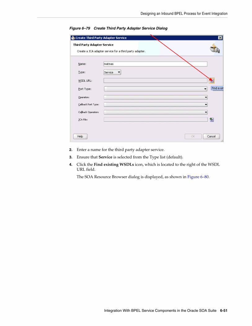
Designing an Inbound BPEL Process for Event Integration
Integration With BPEL Service Components in the Oracle SOA Suite 6-51
Figure 6–79 Create Third Party Adapter Service Dialog
2. Enter a name for the third party adapter service.
3. Ensure that Service is selected from the Type list (default).
4. Click the Find existing WSDLs icon, which is located to the right of the WSDL URL field.
The SOA Resource Browser dialog is displayed, as shown in Figure 6–80.

Designing an Inbound BPEL Process for Event Integration
6-52 Oracle Fusion Middleware Application Adapter for SAP R/3 (SAP JCo 3.0) User's Guide for Oracle WebLogic Server
Figure 6–80 SOA Resource Browser Dialog
5. Browse and select an inbound WSDL file from the following directory:
<ADAPTER_HOME>\soa\thirdparty\ApplicationAdapters\wsdls
6. Click OK.
The Localize Files dialog is displayed, as shown in Figure 6–81.

Designing an Inbound BPEL Process for Event Integration
Integration With BPEL Service Components in the Oracle SOA Suite 6-53
Figure 6–81 Localize Files Dialog
7. Click OK.
The inbound WSDL file and associated receive/request XML schema file (.xsd) are imported to the project folder that has been created.
You are returned to the Create Third Party Adapter Service dialog, as shown in Figure 6–82.
Figure 6–82 Create Third Party Adapter Service Dialog

Designing an Inbound BPEL Process for Event Integration
6-54 Oracle Fusion Middleware Application Adapter for SAP R/3 (SAP JCo 3.0) User's Guide for Oracle WebLogic Server
8. Click the Find JCA file icon, which is located to the right of the JCA File field.
The SOA Resource Browser dialog is displayed, as shown in Figure 6–83.
Figure 6–83 SOA Resource Browser Dialog
9. Browse and select the JCA properties file from the following directory:
<ADAPTER_HOME>\soa\thirdparty\ApplicationAdapters\wsdls
10. Click OK.
A Copy File message is displayed, as shown in Figure 6–84.
Figure 6–84 Copy File Confirmation Message
11. Click Yes.

Designing an Inbound BPEL Process for Event Integration
Integration With BPEL Service Components in the Oracle SOA Suite 6-55
A copy of the JCA properties file is made in the project folder.
You are returned to the Create Third Party Adapter Service dialog, as shown in Figure 6–85.
Figure 6–85 Create Third Party Adapter Service Dialog
12. Click OK.
The third party adapter service component (matmas) is created and displayed in the Exposed Services pane, as shown in Figure 6–86.
Figure 6–86 Third Party Adapter Service Component
You are now ready to configure an inbound BPEL process component.

Designing an Inbound BPEL Process for Event Integration
6-56 Oracle Fusion Middleware Application Adapter for SAP R/3 (SAP JCo 3.0) User's Guide for Oracle WebLogic Server
Creating an Inbound BPEL Process ComponentPerform the following steps to create an inbound BPEL process component:
1. Drag and drop the BPEL Process component from the Service Components pane to the Components pane, as shown in Figure 6–87.
Figure 6–87 BPEL Process Component
The Create BPEL Process dialog is displayed, as shown in Figure 6–88.
Figure 6–88 Create BPEL Process Dialog

Designing an Inbound BPEL Process for Event Integration
Integration With BPEL Service Components in the Oracle SOA Suite 6-57
2. In the Name field, enter a name to identify the new inbound BPEL process component (for example, matmas_inbound).
3. From the Template list, select Base on a WSDL.
4. Uncheck the Expose as SOAP service check box.
5. Click the Find existing WSDLs icon, which is located to the right of the WSDL URL field.
The SOA Resource Browser dialog is displayed, as shown in Figure 6–89.
Figure 6–89 SOA Resource Browser Dialog
6. Browse and select an inbound WSDL file from the project folder.
For example:
C:\JDeveloper\mywork\MySAP_sep23\matmas01\MATMAS01_receive.wsdl
7. Click OK.
You are returned to the Create BPEL Process dialog, as shown in Figure 6–90.

Designing an Inbound BPEL Process for Event Integration
6-58 Oracle Fusion Middleware Application Adapter for SAP R/3 (SAP JCo 3.0) User's Guide for Oracle WebLogic Server
Figure 6–90 Create BPEL Process Dialog
8. Click OK.
Figure 6–91 Created Connection
9. Create a connection between the third party adapter service component (matmas) and the inbound BPEL process component (matmas_inbound), as shown in Figure 6–91.
10. Double-click composite.xml in the left pane.

Designing an Inbound BPEL Process for Event Integration
Integration With BPEL Service Components in the Oracle SOA Suite 6-59
Figure 6–92 Save All Icon
11. Click the Save All icon in the menu bar to save the new inbound BPEL process component that was configured, as shown in Figure 6–92.
You are now ready to deploy the BPEL inbound process.
6.5.4 Deploying the BPEL Inbound ProcessPerform the following steps to deploy the BPEL inbound process.
1. Right-click the project name in the left pane (for example, matmas01), select Deploy, and click matmas01, as shown in Figure 6–93.

Designing an Inbound BPEL Process for Event Integration
6-60 Oracle Fusion Middleware Application Adapter for SAP R/3 (SAP JCo 3.0) User's Guide for Oracle WebLogic Server
Figure 6–93 Matmas01 Option
The Deployment Action page is displayed, as shown in Figure 6–94.

Designing an Inbound BPEL Process for Event Integration
Integration With BPEL Service Components in the Oracle SOA Suite 6-61
Figure 6–94 Deployment Action Page
2. Ensure that Deploy to Application Server is selected.
3. Click Next.
The Deploy Configuration page is displayed, as shown in Figure 6–95.

Designing an Inbound BPEL Process for Event Integration
6-62 Oracle Fusion Middleware Application Adapter for SAP R/3 (SAP JCo 3.0) User's Guide for Oracle WebLogic Server
Figure 6–95 Deploy Configuration Page
4. Leave the default values selected and click Next.
The Select Server page is displayed, as shown in Figure 6–96.
Figure 6–96 Select Server Page

Designing an Inbound BPEL Process for Event Integration
Integration With BPEL Service Components in the Oracle SOA Suite 6-63
5. Select an available application server that was configured and click Next.
The SOA Servers page is displayed, as shown in Figure 6–97.
Figure 6–97 SOA Servers Page
6. Select a target SOA server and click Next.
The Summary page is displayed, as shown in Figure 6–98.

Designing an Inbound BPEL Process for Event Integration
6-64 Oracle Fusion Middleware Application Adapter for SAP R/3 (SAP JCo 3.0) User's Guide for Oracle WebLogic Server
Figure 6–98 Summary Page
7. Review and verify all the available deployment information for your project and click Finish.
The process is deployed successfully, as shown in Figure 6–99.
Figure 6–99 Successful Deployment Message
Once event messages are triggered through SAP GUI, successful instances are received in the Oracle Enterprise Manager console, as shown in Figure 6–100.

Designing an Inbound BPEL Process for Event Integration
Integration With BPEL Service Components in the Oracle SOA Suite 6-65
Figure 6–100 Received Instances
6.5.5 Triggering an Event in SAP R/3Events are generated by activity in an application system. For example, SAP R/3 may generate an event as customer information is updated in the system. For more information on events, see "Configuring an Event Adapter" on page 4-19.
The following topics describe how to trigger an event in SAP R/3 and verify event integration using Oracle Application Adapter for SAP R/3.
To trigger an event in SAP R/3:
1. Start the SAP Workbench and log in to the SAP R/3 system, as shown in Figure 6–101.
Figure 6–101 SAP Workbench
2. Run the bd12 transaction.

Designing an Inbound BPEL Process for Event Integration
6-66 Oracle Fusion Middleware Application Adapter for SAP R/3 (SAP JCo 3.0) User's Guide for Oracle WebLogic Server
Figure 6–102 Send Customers Window
Enter the following information in the Send Customers window:
a. In the Customer field, enter a customer number with a range from 1 to 3, as shown in Figure 6–102.
b. In the Output type field, enter DEBMAS.
c. In the Logical system field, specify the logical system you are using with SAP R/3.
3. Click the check mark icon in the upper left-hand corner, as shown in Figure 6–103.
Figure 6–103 Restrictions Page
4. Ensure DEBMAS appears in the Message type column.
5. Click the Execute button.
Customer master data is sent to the logical system specified. If a channel in Application Explorer defined the Program ID with the same value, then the channel receives this customer master data from SAP R/3.
Verifying the ResultsTo verify your results:
1. Logon to the Oracle Enterprise Manager console by using the following URL:
http://localhost:7001/em
2. Expand your domain in the left pane followed by the SOA folder.
3. Select an available inbound BPEL process (for example, matmas01), as shown in Figure 6–104.
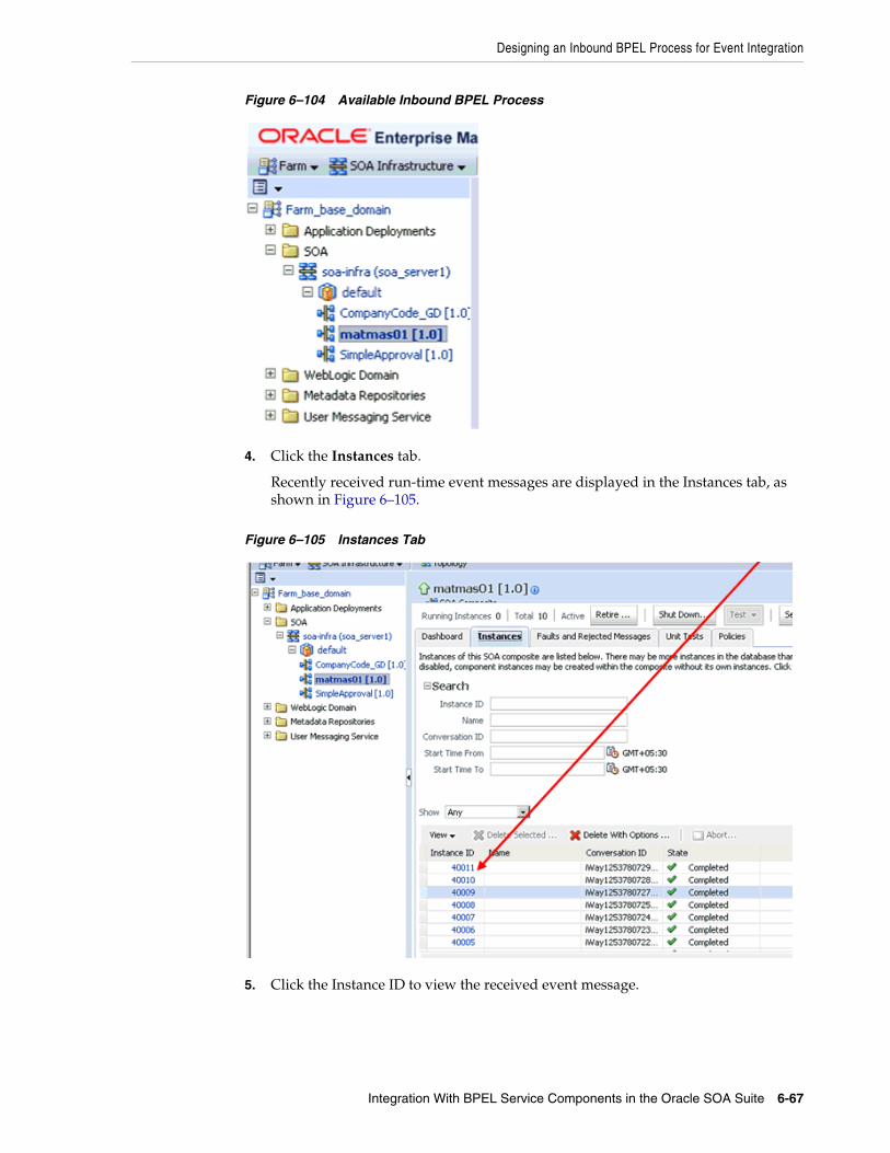
Designing an Inbound BPEL Process for Event Integration
Integration With BPEL Service Components in the Oracle SOA Suite 6-67
Figure 6–104 Available Inbound BPEL Process
4. Click the Instances tab.
Recently received run-time event messages are displayed in the Instances tab, as shown in Figure 6–105.
Figure 6–105 Instances Tab
5. Click the Instance ID to view the received event message.

Designing an Inbound BPEL Process for Event Integration
6-68 Oracle Fusion Middleware Application Adapter for SAP R/3 (SAP JCo 3.0) User's Guide for Oracle WebLogic Server

7
Integration With Mediator Service Components in the Oracle SOA Suite 7-1
7 Integration With Mediator ServiceComponents in the Oracle SOA Suite
This chapter describes integration with Mediator service components in the Oracle SOA Suite. It contains the following topics:
■ Section 7.1, "Configuring a New Application Server Connection"
■ Section 7.2, "Configuring a Mediator Outbound Process"
■ Section 7.3, "Configuring a Mediator Inbound Process"
The scenarios shown in this chapter require the following prerequisites.
PrerequisitesThe following are installation and configuration requirements:
■ Oracle Application Adapter for SAP R/3 must be installed on Oracle WebLogic Server.
■ SAP R/3 must be configured for inbound and outbound processing. For more information, see Appendix A, "Understanding the SAP System Role in Remote Processing".
The examples in this chapter present the configuration steps necessary for demonstrating service and event integration with SAP R/3. Prior to using this material, you must be familiar with the following:
■ How to configure Oracle Application Adapter for SAP R/3 for services and events. For more information, see Chapter 4, "Configuring Oracle Application Adapter for SAP R/3".
■ How to configure Oracle JDeveloper. For more information, see Chapter 6, "Integration With BPEL Service Components in the Oracle SOA Suite".
Overview of Mediator IntegrationMediator provides a comprehensive application integration framework. Oracle Application Adapter for SAP R/3 used with Mediator enables you to seamlessly integrate enterprise software, eliminating custom code. Functional modeling, as opposed to custom coding solutions, allows for software reuse and reduces the complexity and management challenges that arise over the software lifecycle. This integration model consists of two components--high-level integration logic and low-level platform services.
Adapter integration with Oracle Mediator is a two-step process:
1. Design Time: Oracle Application Adapter for SAP R/3 is configured in Application Explorer for services and events, as described in Chapter 4,

Configuring a New Application Server Connection
7-2 Oracle Fusion Middleware Application Adapter for SAP R/3 (SAP JCo 3.0) User's Guide for Oracle WebLogic Server
"Configuring Oracle Application Adapter for SAP R/3". Integration logic is modeled in Mediator.
2. Runtime: The underlying platform treats this metadata as run-time instructions to enable the communication between participating applications.
7.1 Configuring a New Application Server ConnectionFor more information on how to configure a new Application Server connection in Oracle JDeveloper, see Section 6.3, "Configuring a New Application Server Connection".
7.2 Configuring a Mediator Outbound ProcessThe following example describes how to configure a Mediator outbound process to your SAP R/3 system, using a Mediator project in Oracle JDeveloper.
PrerequisitesBefore you design a Mediator outbound process, you must generate the respective WSDL file using Application Explorer. For more information, see "Generating WSDL for Request/Response Service" on page 6-8.
7.2.1 Creating an Empty Composite for SOAPerform the following steps to create an empty composite for SOA:
1. Create a new SOA application.
2. Enter a name for the new SOA Application and click Next, as shown in Figure 7–1.
Figure 7–1 Name Your Application Page
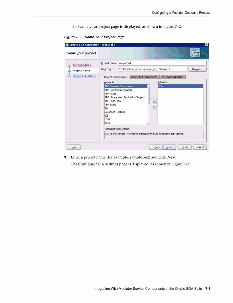
Configuring a Mediator Outbound Process
Integration With Mediator Service Components in the Oracle SOA Suite 7-3
The Name your project page is displayed, as shown in Figure 7–2.
Figure 7–2 Name Your Project Page
3. Enter a project name (for example, sampleTest) and click Next.
The Configure SOA settings page is displayed, as shown in Figure 7–3.

Configuring a Mediator Outbound Process
7-4 Oracle Fusion Middleware Application Adapter for SAP R/3 (SAP JCo 3.0) User's Guide for Oracle WebLogic Server
Figure 7–3 Configure SOA Settings Page
4. From the Composite Template list, select Empty Composite and click Finish.
7.2.2 Defining a Mediator Outbound ProcessThis section describes how to define a Mediator outbound process, which consists of the following stages:
1. Configuring a Third Party Adapter Service Component
2. Configuring an Outbound Mediator Process Component
3. Configuring the Routing Rules
Configuring a Third Party Adapter Service ComponentPerform the following steps to create a third party adapter service component:
1. Drag and drop the Third Party Adapter component from the Service Adapters pane to the External References pane, as shown in Figure 7–4.

Configuring a Mediator Outbound Process
Integration With Mediator Service Components in the Oracle SOA Suite 7-5
Figure 7–4 Third Party Adapter Component
The Create Third Party Adapter Service dialog is displayed, as shown in Figure 7–5.
Figure 7–5 Create Third Party Adapter Service Dialog
2. Enter a name for the third party adapter service.
3. Ensure that Reference is selected from the Type drop-down list (default).
4. Click the Find existing WSDLs icon, which is located to the right of the WSDL URL field.
The SOA Resource Browser dialog is displayed, as shown in Figure 7–6.

Configuring a Mediator Outbound Process
7-6 Oracle Fusion Middleware Application Adapter for SAP R/3 (SAP JCo 3.0) User's Guide for Oracle WebLogic Server
Figure 7–6 SOA Resource Browser Dialog
5. Browse and select an outbound WSDL file from the following directory:
<ADAPTER_HOME>\soa\thirdparty\ApplicationAdapters\wsdls
6. Click OK.
The Localize Files dialog is displayed, as shown in Figure 7–7.

Configuring a Mediator Outbound Process
Integration With Mediator Service Components in the Oracle SOA Suite 7-7
Figure 7–7 Localize Files Dialog
7. Click OK.
The outbound WSDL file and associated request and response XML schema files (.xsd) are imported to the project folder that has been created.
You are returned to the Create Third Party Adapter Service dialog, as shown in Figure 7–8.
Figure 7–8 Create Third Party Adapter Service Dialog

Configuring a Mediator Outbound Process
7-8 Oracle Fusion Middleware Application Adapter for SAP R/3 (SAP JCo 3.0) User's Guide for Oracle WebLogic Server
8. Click the Find JCA file icon, which is located to the right of the JCA File field.
The SOA Resource Browser dialog is displayed, as shown in Figure 7–9.
Figure 7–9 SOA Resource Browser Dialog
9. Browse and select the JCA properties file from the following directory:
<ADAPTER_HOME>\soa\thirdparty\ApplicationAdapters\wsdls
10. Click OK.
A Copy File confirmation message is displayed, as shown in Figure 7–10.
Figure 7–10 Copy File Confirmation Message
11. Click Yes.

Configuring a Mediator Outbound Process
Integration With Mediator Service Components in the Oracle SOA Suite 7-9
A copy of the JCA properties file is made in the project folder.
You are returned to the Create Third Party Adapter Service dialog, as shown in Figure 7–11.
Figure 7–11 Create Third Party Adapter Service Dialog
12. Click OK.
The third party adapter service component (GetDetail) is created in the External References pane, as shown in Figure 7–12.

Configuring a Mediator Outbound Process
7-10 Oracle Fusion Middleware Application Adapter for SAP R/3 (SAP JCo 3.0) User's Guide for Oracle WebLogic Server
Figure 7–12 Third Party Adapter Service Component (Get Detail)
You are now ready to configure an outbound Mediator process component.
Configuring an Outbound Mediator Process ComponentPerform the following steps to configure an outbound Mediator process component:
1. Drag and drop the Mediator Process component from the Service Components pane to the Components pane, as shown in Figure 7–13.

Configuring a Mediator Outbound Process
Integration With Mediator Service Components in the Oracle SOA Suite 7-11
Figure 7–13 Mediator Process Component
The Create Mediator dialog is displayed, as shown in Figure 7–14.
Figure 7–14 Create Mediator Dialog
2. In the Name field, enter a name to identify the new outbound Mediator process component (for example, CompanyCode_GetDetail).
3. From the Template drop-down list, select Synchronous Interface.

Configuring a Mediator Outbound Process
7-12 Oracle Fusion Middleware Application Adapter for SAP R/3 (SAP JCo 3.0) User's Guide for Oracle WebLogic Server
4. Click the Browse icon, which is located to the right of the Input field to select the associated XML request schema file.
The Type Chooser dialog is displayed, as shown in Figure 7–15.
Figure 7–15 Type Chooser Dialog
5. Expand Project WSDL Files, CC_GetDetail_invoke_Nov18.wsdl, Inline Schemas, and select CompanyCode.GetDetail.
6. Click OK.
You are returned to the Create Mediator dialog, as shown in Figure 7–16.

Configuring a Mediator Outbound Process
Integration With Mediator Service Components in the Oracle SOA Suite 7-13
Figure 7–16 Create Mediator Dialog
7. Click the Browse icon, which is located to the right of the Output field to select the associated XML response schema file.
The Type Chooser dialog is displayed, as shown in Figure 7–17.

Configuring a Mediator Outbound Process
7-14 Oracle Fusion Middleware Application Adapter for SAP R/3 (SAP JCo 3.0) User's Guide for Oracle WebLogic Server
Figure 7–17 Type Chooser Dialog
8. Expand Project WSDL Files, CC_GetDetail_invoke_Nov18.wsdl, Inline Schemas, schema, and select CompanyCode.GetDetailResponse.
9. Click OK.
You are returned to the Create Mediator dialog, as shown in Figure 7–18.

Configuring a Mediator Outbound Process
Integration With Mediator Service Components in the Oracle SOA Suite 7-15
Figure 7–18 Create Mediator Dialog
10. Click OK.
11. Create a connection between the outbound Mediator process component (CompanyCode_ GetDetail) and the third party adapter service component (GetDetail), as shown in Figure 7–19.
Figure 7–19 Created Connection
You are now ready to configure the routing rules.

Configuring a Mediator Outbound Process
7-16 Oracle Fusion Middleware Application Adapter for SAP R/3 (SAP JCo 3.0) User's Guide for Oracle WebLogic Server
Configuring the Routing RulesPerform the following steps to configure routing rules for the Mediator outbound process component:
1. Double-click the outbound Mediator process component (CompanyCode_ GetDetail) in the Components pane, as shown in Figure 7–20.
Figure 7–20 Mediator Process Component
The Routing Rules dialog is displayed, as shown in Figure 7–21.
Figure 7–21 Routing Rules Dialog
2. In the <<Filter Expression>> area, click the icon to the right of the Transform Using field.
The Request Transformation Map dialog is displayed, as shown in Figure 7–22.

Configuring a Mediator Outbound Process
Integration With Mediator Service Components in the Oracle SOA Suite 7-17
Figure 7–22 Request Transformation Map Dialog
3. Select the Create New Mapper File option and click OK.
The following mapping page is displayed, as shown in Figure 7–23.
Figure 7–23 Mapping Page
4. Map the iWayRequest:CompanyCode.GetDetail source element to the iWayRequest:CompanyCode.GetDetail target element.
The Auto Map Preferences dialog is displayed, as shown in Figure 7–24.

Configuring a Mediator Outbound Process
7-18 Oracle Fusion Middleware Application Adapter for SAP R/3 (SAP JCo 3.0) User's Guide for Oracle WebLogic Server
Figure 7–24 Auto Map Preferences Dialog
5. Retain the default values and click OK.
You are returned to the Routing Rules dialog, as shown in Figure 7–25.
Figure 7–25 Routing Rules Dialog
6. In the Synchronous Reply area, click the icon to the right of the Transform Using field.
The Reply Transformation Map dialog is displayed, as shown in Figure 7–26.

Configuring a Mediator Outbound Process
Integration With Mediator Service Components in the Oracle SOA Suite 7-19
Figure 7–26 Reply Transformation Map Dialog
7. Select the Create New Mapper File option and click OK.
A mapping page is displayed, as shown in Figure 7–27.
Figure 7–27 Mapping Page
8. Map the iWayResponse:CompanyCode.GetDetail.Response source element to the iWayResponse:CompanyCode.GetDetail.Response target element.
The Auto Map Preferences dialog is displayed, as shown in Figure 7–28.

Configuring a Mediator Outbound Process
7-20 Oracle Fusion Middleware Application Adapter for SAP R/3 (SAP JCo 3.0) User's Guide for Oracle WebLogic Server
Figure 7–28 Auto Map Preferences Dialog
9. Retain the default values and click OK.
The mapping is completed, as shown in Figure 7–29.
Figure 7–29 Completed Mapping
10. Click the Save All icon in the menu bar to save the new outbound Mediator process component that was configured.
You are now ready to deploy the Mediator outbound process.
7.2.3 Deploying the Mediator Outbound ProcessPerform the following steps to deploy the Mediator outbound process.
1. Right-click the project name in the left pane (for example, sampleTest), select Deploy from the context menu, and click sampleTest, as shown in Figure 7–30.

Configuring a Mediator Outbound Process
Integration With Mediator Service Components in the Oracle SOA Suite 7-21
Figure 7–30 SampleTest Option
The Deployment Action page is displayed, as shon in Figure 7–31.

Configuring a Mediator Outbound Process
7-22 Oracle Fusion Middleware Application Adapter for SAP R/3 (SAP JCo 3.0) User's Guide for Oracle WebLogic Server
Figure 7–31 Deployment Action
2. Ensure that Deploy to Application Server is selected.
3. Click Next.
The Deploy Configuration page is displayed, as shown in Figure 7–32.

Configuring a Mediator Outbound Process
Integration With Mediator Service Components in the Oracle SOA Suite 7-23
Figure 7–32 Deploy Configuration Page
4. Leave the default values selected and click Next.
The Select Server page is displayed, as shown in Figure 7–33.
Figure 7–33 Select Server Page

Configuring a Mediator Outbound Process
7-24 Oracle Fusion Middleware Application Adapter for SAP R/3 (SAP JCo 3.0) User's Guide for Oracle WebLogic Server
5. Select an available application server that was configured and click Next.
The SOA Servers page is displayed, as shown in Figure 7–34.
Figure 7–34 SOA Servers Page
6. Select a target SOA server and click Next.
The Summary page is displayed, as shown in Figure 7–35.

Configuring a Mediator Outbound Process
Integration With Mediator Service Components in the Oracle SOA Suite 7-25
Figure 7–35 Summary Page
7. Review and verify all the available deployment information for your project and click Finish.
The process is deployed successfully, as shown in Figure 7–36.
Figure 7–36 Successful Deployment Message
7.2.4 Invoking the Input XML Document in the Oracle Enterprise Manager ConsolePerform the following steps to invoke the input XML document in the Oracle Enterprise Manager console.
1. Logon to the Oracle Enterprise Manager console, as shown in Figure 7–37.

Configuring a Mediator Outbound Process
7-26 Oracle Fusion Middleware Application Adapter for SAP R/3 (SAP JCo 3.0) User's Guide for Oracle WebLogic Server
Figure 7–37 Oracle Enterprise Manager Console
2. Expand your domain in the left pane followed by the SOA folder.
3. Select an available project in the left pane.
4. Click Test.
5. Click the Request tab, as shown in Figure 7–38.
Figure 7–38 Request Tab
6. Provide an appropriate input value in the Input Arguments area and click Test Web Service.
The output response is received in the Oracle Enterprise Manager console, as shown in Figure 7–39.
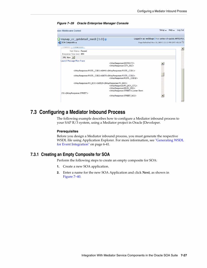
Configuring a Mediator Inbound Process
Integration With Mediator Service Components in the Oracle SOA Suite 7-27
Figure 7–39 Oracle Enterprise Manager Console
7.3 Configuring a Mediator Inbound ProcessThe following example describes how to configure a Mediator inbound process to your SAP R/3 system, using a Mediator project in Oracle JDeveloper.
PrerequisitesBefore you design a Mediator inbound process, you must generate the respective WSDL file using Application Explorer. For more information, see "Generating WSDL for Event Integration" on page 6-41.
7.3.1 Creating an Empty Composite for SOAPerform the following steps to create an empty composite for SOA:
1. Create a new SOA application.
2. Enter a name for the new SOA Application and click Next, as shown in Figure 7–40.

Configuring a Mediator Inbound Process
7-28 Oracle Fusion Middleware Application Adapter for SAP R/3 (SAP JCo 3.0) User's Guide for Oracle WebLogic Server
Figure 7–40 Name Your Application Page
The Name your project page is displayed, as shown in Figure 7–41.
Figure 7–41 Name Your Project Page
3. Enter a project name and click Next.

Configuring a Mediator Inbound Process
Integration With Mediator Service Components in the Oracle SOA Suite 7-29
The Configure SOA settings page is displayed, as shown in Figure 7–42.
Figure 7–42 Configure SOA Settings Page
4. From the Composite Template list, select Empty Composite and click Finish.
7.3.2 Defining a Mediator Inbound ProcessThis section describes how to define a Mediator inbound process, which consists of the following stages:
1. Configuring a Third Party Adapter Service Component
2. Configuring an Inbound Mediator Process Component With a File Adapter
3. Configuring the Routing Rules
Configuring a Third Party Adapter Service ComponentPerform the following steps to create a third party adapter service component:
1. Drag and drop the Third Party Adapter component from the Service Adapters pane to the Exposed Services pane, as shown in Figure 7–43.

Configuring a Mediator Inbound Process
7-30 Oracle Fusion Middleware Application Adapter for SAP R/3 (SAP JCo 3.0) User's Guide for Oracle WebLogic Server
Figure 7–43 Third Party Adapter Component
The Create Third Party Adapter Service dialog is displayed, as shown in Figure 7–44.
Figure 7–44 Create Third Party Adapter Service Dialog
2. Enter a name for the third party adapter service (for example, CC_GetDetail_Mediator_IB).
3. Ensure that Service is selected from the Type drop-down list (default).
4. Click the Find existing WSDLs icon, which is located to the right of the WSDL URL field.
The SOA Resource Browser dialog is displayed, as shown in Figure 7–45.

Configuring a Mediator Inbound Process
Integration With Mediator Service Components in the Oracle SOA Suite 7-31
Figure 7–45 SOA Resource Browser Dialog
5. Browse and select an inbound WSDL file from the following directory:
<ADAPTER_HOME>\soa\thirdparty\ApplicationAdapters\wsdls
6. Click OK.
The Localize Files dialog is displayed, as shown in Figure 7–46.

Configuring a Mediator Inbound Process
7-32 Oracle Fusion Middleware Application Adapter for SAP R/3 (SAP JCo 3.0) User's Guide for Oracle WebLogic Server
Figure 7–46 Localize Files Dialog
7. Click OK.
The inbound WSDL file and associated receive/request schema file (.xsd) are imported to the project folder that has been created.
You are returned to the Create Third Party Adapter Service dialog, as shown in Figure 7–47.
Figure 7–47 Create Third Party Adapter Service Dialog

Configuring a Mediator Inbound Process
Integration With Mediator Service Components in the Oracle SOA Suite 7-33
8. Click the Find JCA file icon, which is located to the right of the JCA File field.
The SOA Resource Browser dialog is displayed, as shown in Figure 7–48.
Figure 7–48 SOA Resourve Browser Dialog
9. Browse and select the JCA properties file from the following directory:
<ADAPTER_HOME>\soa\thirdparty\ApplicationAdapters\wsdls
10. Click OK.
The following message is displayed, as shown in Figure 7–49.
Figure 7–49 Copy File Confirmation Message

Configuring a Mediator Inbound Process
7-34 Oracle Fusion Middleware Application Adapter for SAP R/3 (SAP JCo 3.0) User's Guide for Oracle WebLogic Server
11. Click Yes.
A copy of the JCA properties file is made in the project folder.
You are returned to the Create Third Party Adapter Service dialog, as shown in Figure 7–50.
Figure 7–50 Create Third Party Adapter Service Dialog
12. Click OK.
The third party adapter service component (CC_GetDetail_Mediator_IB) is created in the Exposed Services pane, as shown in Figure 7–51.

Configuring a Mediator Inbound Process
Integration With Mediator Service Components in the Oracle SOA Suite 7-35
Figure 7–51 Third Party Adapter Service Component
You are now ready to configure an inbound Mediator process component.
Configuring an Inbound Mediator Process Component With a File AdapterPerform the following steps to configure an inbound Mediator process component with a File adapter.
1. Drag and drop the Mediator Process component from the Service Components pane to the Components pane, as shown in Figure 7–52.

Configuring a Mediator Inbound Process
7-36 Oracle Fusion Middleware Application Adapter for SAP R/3 (SAP JCo 3.0) User's Guide for Oracle WebLogic Server
Figure 7–52 Mediator Process Component
The Create Mediator dialog is displayed, as shown in Figure 7–53.
Figure 7–53 Create Mediator Dialog
2. In the Name field, enter a name to identify the new inbound Mediator process component (for example, CC_GetDetail_Mediator_IB).
3. From the Template drop-down list, select Define Interface Later.
4. Click the OK.

Configuring a Mediator Inbound Process
Integration With Mediator Service Components in the Oracle SOA Suite 7-37
The new Mediator process component is added to the Components pane, as shown in Figure 7–54.
Figure 7–54 Mediator Process Component
5. Drag and drop the File Adapter component from the Service Adapters pane to the External References pane.
The Adapter Configuration Wizard is displayed, showing the Service Name page, as shown in Figure 7–55.

Configuring a Mediator Inbound Process
7-38 Oracle Fusion Middleware Application Adapter for SAP R/3 (SAP JCo 3.0) User's Guide for Oracle WebLogic Server
Figure 7–55 Adapter Configuration Wizard
6. Type a name for the new File adapter in the Service Name field and click Next.
The Adapter Interface page is displayed, as shown in Figure 7–56.

Configuring a Mediator Inbound Process
Integration With Mediator Service Components in the Oracle SOA Suite 7-39
Figure 7–56 Adapter Interface Page
7. Ensure that the Define from operation and schema (specified later) option is selected.
8. Click Next.
The Operation page is displayed, as shown in Figure 7–57.

Configuring a Mediator Inbound Process
7-40 Oracle Fusion Middleware Application Adapter for SAP R/3 (SAP JCo 3.0) User's Guide for Oracle WebLogic Server
Figure 7–57 Operation Page
9. Select Write File from the list of Operation Type options and specify an Operation Name (for example, Write).
10. Click Next.
The File Configuration page is displayed, as shown in Figure 7–58.

Configuring a Mediator Inbound Process
Integration With Mediator Service Components in the Oracle SOA Suite 7-41
Figure 7–58 File Configuration Page
11. Specify a location on your file system where the output file is written.
12. In the File Naming Convention field, specify a name for the output file.
13. Click Next.
The Messages page is displayed, as shown in Figure 7–59.
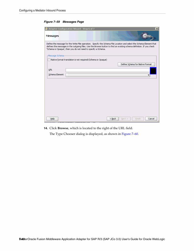
Configuring a Mediator Inbound Process
7-42 Oracle Fusion Middleware Application Adapter for SAP R/3 (SAP JCo 3.0) User's Guide for Oracle WebLogic Server
Figure 7–59 Messages Page
14. Click Browse, which is located to the right of the URL field.
The Type Chooser dialog is displayed, as shown in Figure 7–60.

Configuring a Mediator Inbound Process
Integration With Mediator Service Components in the Oracle SOA Suite 7-43
Figure 7–60 Type Chooser Dialog
15. Expand Project WSDL Files, BAPI_COMPANYCODE_GETDETAIL_receive.wsdl, Inline Schemas, and schema.
16. Select the available schema (for example, BAPI.CompanyCode.GetDetail)
17. Click OK.
You are returned to the Messages page, as shown in Figure 7–61.
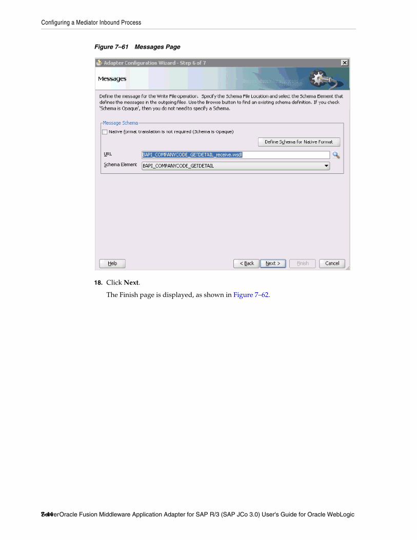
Configuring a Mediator Inbound Process
7-44 Oracle Fusion Middleware Application Adapter for SAP R/3 (SAP JCo 3.0) User's Guide for Oracle WebLogic Server
Figure 7–61 Messages Page
18. Click Next.
The Finish page is displayed, as shown in Figure 7–62.

Configuring a Mediator Inbound Process
Integration With Mediator Service Components in the Oracle SOA Suite 7-45
Figure 7–62 Finish Page
19. Click Finish.
20. Create a connection between the inbound Mediator process component and the third party adapter service component, as shown in Figure 7–63.
Figure 7–63 Created Connection

Configuring a Mediator Inbound Process
7-46 Oracle Fusion Middleware Application Adapter for SAP R/3 (SAP JCo 3.0) User's Guide for Oracle WebLogic Server
21. Create a connection between the inbound Mediator process component and the File adapter component, as shown in Figure 7–64.
Figure 7–64 Created Connection
You are now ready to configure the routing rules.
Configuring the Routing RulesPerform the following steps to configure routing rules for the Mediator inbound process component:
1. Double-click the inbound Mediator process component in the Components page, as shown in Figure 7–65.
Figure 7–65 Inbound Mediator Process Component
The Routing Rules dialog is displayed, as shown in Figure 7–66.

Configuring a Mediator Inbound Process
Integration With Mediator Service Components in the Oracle SOA Suite 7-47
Figure 7–66 Routing Rules Dialog
2. In the <<Filter Expression>> area, click the icon to the right of the Transform Using field.
The Request Transformation Map dialog is displayed, as shown in Figure 7–67.
Figure 7–67 Request Transformation Map Dialog
3. Select the Create New Mapper File option and click OK.
The mapping page is displayed, as shown in Figure 7–68.
Figure 7–68 Mapping Page

Configuring a Mediator Inbound Process
7-48 Oracle Fusion Middleware Application Adapter for SAP R/3 (SAP JCo 3.0) User's Guide for Oracle WebLogic Server
4. Map the iWayEvent:BAPI_COMPANYCODE_GETDETAIL source element to the iWayEvent:BAPI_COMPANYCODE_GETDETAIL target element.
The Auto Map Preferences dialog is displayed, as shown in Figure 7–69.
Figure 7–69 Auto Map Preferences Dialog
5. Retain the default values and click OK.
You are returned to the Routing Rules dialog. The mapping is now complete.
6. Click the Save All icon in the menu bar to save the new inbound Mediator process component that was configured.
You are now ready to deploy the Mediator inbound process. You can follow the same procedure in "Deploying the BPEL Inbound Process" on page 6-59.
Once event messages are triggered through SAP GUI, output XML is received in the location that was specified for the File adapter component. For more information on triggering events in SAP R/3, see "Triggering an Event in SAP R/3" on page 6-65.

8
Integration With BPM Service Components in the Oracle SOA Suite 8-1
8 Integration With BPM Service Componentsin the Oracle SOA Suite
Oracle Application Adapter for SAP R/3 integrates seamlessly with Business Process Management (BPM) to facilitate Web service integration. Oracle BPM is based on the Service-Oriented Architecture (SOA). It consumes adapter services exposed as Web Service Definition Language (WSDL) documents.
This chapter contains the following topics:
■ Section 8.1, "Overview"
■ Section 8.2, "Deployment of Adapter"
■ Section 8.3, "Configuring a New Application Server Connection"
■ Section 8.4, "Designing an Outbound BPM Process Using Transformations for Service Integration"
■ Section 8.5, "Designing an Inbound BPM Process Using Transformations for Event Integration"
8.1 OverviewTo integrate with Oracle BPM, Oracle Application Adapter for SAP R/3 must be deployed in the same WLS container as Oracle BPM. The underlying adapter services must be exposed as WSDL files, which are generated during design time in Oracle Adapter Application Explorer (Application Explorer) for both request-response (outbound) and event notification (inbound) services of the adapter. For more information, see "Generating WSDL (J2CA Configurations Only)" on page 4-15.
The generated WSDL files are used to design the appropriate BPM processes for inbound or outbound adapter services. A completed BPM process must be successfully compiled in JDeveloper and deployed to a BPM server. Upon deployment to the BPM server, every newly built process is automatically deployed to the Oracle Enterprise Manager console, where you run, monitor, and administer BPM processes, and listen to adapter events.
8.2 Deployment of AdapterDuring installation, Oracle Application Adapter for SAP R/3 is deployed as a J2CA 1.0 resource adapter within the WLS container. The adapter must be deployed in the same WLS container as Oracle BPM.

Configuring a New Application Server Connection
8-2 Oracle Fusion Middleware Application Adapter for SAP R/3 (SAP JCo 3.0) User's Guide for Oracle WebLogic Server
8.3 Configuring a New Application Server ConnectionFor more information on how to configure a new Application Server connection in Oracle JDeveloper, see Section 6.3, "Configuring a New Application Server Connection".
8.4 Designing an Outbound BPM Process Using Transformations for Service Integration
The following tools are required to complete your outbound design-time configuration:
■ Oracle Adapter Application Explorer (Application Explorer)
■ Oracle JDeveloper BPM Designer (JDeveloper) or Eclipse
Before you design a BPM process, you must generate the respective WSDL file using Application Explorer. For more information, see "Generating WSDL for Request/Response Service" on page 6-8.
8.4.1 Creating an Empty Composite for BPMPerform the following steps to create an empty composite for BPM:
1. Create a new BPM application.
2. Enter a name for the new BPM application and click Next, as shown in Figure 8–1.
Note: The examples in this chapter demonstrate the use of JDeveloper.

Designing an Outbound BPM Process Using Transformations for Service Integration
Integration With BPM Service Components in the Oracle SOA Suite 8-3
Figure 8–1 Name Your Application Page
The Name your project page is displayed, as shown in Figure 8–2.
Figure 8–2 Name Your Project Page
3. Enter a project name (for example, Mysap_jca_outbound) and click Next.

Designing an Outbound BPM Process Using Transformations for Service Integration
8-4 Oracle Fusion Middleware Application Adapter for SAP R/3 (SAP JCo 3.0) User's Guide for Oracle WebLogic Server
The Configure SOA settings page is displayed, as shown in Figure 8–3.
Figure 8–3 Configure SOA Settings Page
4. From the Composite Template list, select Empty Composite and click Finish.
8.4.2 Defining a BPM Outbound ProcessThis section describes how to define a BPM outbound process, which consists of the following stages:
1. Configuring a Third Party Adapter Service Component
2. Configuring an Outbound BPM Process Component
3. Creating a File Adapter for the Write Operation
Configuring a Third Party Adapter Service ComponentPerform the following steps to create a third party adapter service component:
1. Drag and drop the Third Party Adapter component from the Service Adapters pane to the External References pane, as shown in Figure 8–4.

Designing an Outbound BPM Process Using Transformations for Service Integration
Integration With BPM Service Components in the Oracle SOA Suite 8-5
Figure 8–4 Third Party Adapter Component
The Create Third Party Adapter Service dialog is displayed, as shown in Figure 8–5.
Figure 8–5 Create Third Party Adapter Service Dialog
2. Enter a name for the third party adapter service.
3. Ensure that Reference is selected from the Type list (default).
4. Click the Find existing WSDLs icon, which is located to the right of the WSDL URL field.
The SOA Resource Browser dialog is displayed, as shown in Figure 8–6.

Designing an Outbound BPM Process Using Transformations for Service Integration
8-6 Oracle Fusion Middleware Application Adapter for SAP R/3 (SAP JCo 3.0) User's Guide for Oracle WebLogic Server
Figure 8–6 SOA Resource Browser Dialog
5. Browse and select an outbound WSDL file from the following directory:
<ADAPTER_HOME>\soa\thirdparty\ApplicationAdapters\wsdls
6. Click OK.
The Localize Files dialog is displayed, as shown in Figure 8–7.

Designing an Outbound BPM Process Using Transformations for Service Integration
Integration With BPM Service Components in the Oracle SOA Suite 8-7
Figure 8–7 Localize Files Dialog
7. Click OK.
The outbound WSDL file and associated request and response XML schema files (.xsd) are imported to the project folder that has been created.
You are returned to the Create Third Party Adapter Service dialog, as shown in Figure 8–8.
Figure 8–8 Create Third Party Adapter Service Dialog

Designing an Outbound BPM Process Using Transformations for Service Integration
8-8 Oracle Fusion Middleware Application Adapter for SAP R/3 (SAP JCo 3.0) User's Guide for Oracle WebLogic Server
8. Click the Find JCA file icon, which is located to the right of the JCA File field.
The SOA Resource Browser dialog is displayed, as shown in Figure 8–9.
Figure 8–9 SOA Resource Browser Dialog
9. Browse and select the JCA properties file from the following directory:
<ADAPTER_HOME>\soa\thirdparty\ApplicationAdapters\wsdls
10. Click OK.
The Copy File message is displayed, as shown in Figure 8–10.
Figure 8–10 Copy File Confirmation Message
11. Click Yes.
A copy of the JCA properties file is made in the project folder.

Designing an Outbound BPM Process Using Transformations for Service Integration
Integration With BPM Service Components in the Oracle SOA Suite 8-9
You are returned to the Create Third Party Adapter Service dialog, as shown in Figure 8–11.
Figure 8–11 Create Third Party Adapter Service Dialog
12. Click OK.
The third party adapter service component (CC_GD) is created and displayed in the External References pane, as shown in Figure 8–12.
Figure 8–12 Third Party Adapter Service Component
You are now ready to configure an outbound BPM process component.

Designing an Outbound BPM Process Using Transformations for Service Integration
8-10 Oracle Fusion Middleware Application Adapter for SAP R/3 (SAP JCo 3.0) User's Guide for Oracle WebLogic Server
Configuring an Outbound BPM Process ComponentPerform the following steps to configure an outbound BPM process component:
1. Drag and drop the BPMN Process component from the Service Components pane to the Components pane, as shown in Figure 8–13.
Figure 8–13 BPMN Process Component
The Create BPMN Process dialog is displayed, as shown in Figure 8–14.
Figure 8–14 Create BPMN Process Dialog
2. Accept the default option that is selected in the left pane (Default Process) and click Finish.
The BPMN Process component is created, as shown in Figure 8–15.

Designing an Outbound BPM Process Using Transformations for Service Integration
Integration With BPM Service Components in the Oracle SOA Suite 8-11
Figure 8–15 BPMN Process Component
3. Double-click the BPMN Process component in the Components pane.
The BPMN process is displayed, as shown in Figure 8–16.
Figure 8–16 BPMN Process
4. Click the Activity icon, as shown in Figure 8–17.

Designing an Outbound BPM Process Using Transformations for Service Integration
8-12 Oracle Fusion Middleware Application Adapter for SAP R/3 (SAP JCo 3.0) User's Guide for Oracle WebLogic Server
Figure 8–17 Activity Icon
5. Drop the Activity icon on the wire between the Start and End event components, as shown in Figure 8–18.
Figure 8–18 Activity Icon
The Properties - Activity dialog is displayed, as shown in Figure 8–19.
Figure 8–19 Properties - Activity Dialog
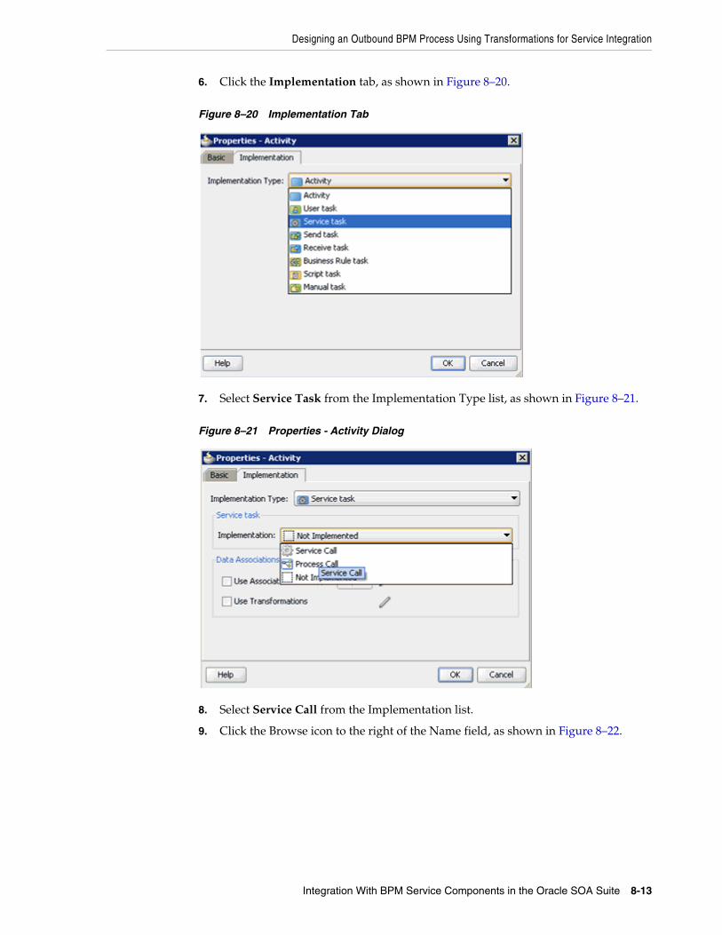
Designing an Outbound BPM Process Using Transformations for Service Integration
Integration With BPM Service Components in the Oracle SOA Suite 8-13
6. Click the Implementation tab, as shown in Figure 8–20.
Figure 8–20 Implementation Tab
7. Select Service Task from the Implementation Type list, as shown in Figure 8–21.
Figure 8–21 Properties - Activity Dialog
8. Select Service Call from the Implementation list.
9. Click the Browse icon to the right of the Name field, as shown in Figure 8–22.

Designing an Outbound BPM Process Using Transformations for Service Integration
8-14 Oracle Fusion Middleware Application Adapter for SAP R/3 (SAP JCo 3.0) User's Guide for Oracle WebLogic Server
Figure 8–22 Browse Icon
The Type dialog is displayed, as shown in Figure 8–23.
Figure 8–23 Type Dialog
10. Select the Third Party Service that has been created and click OK.
You are returned to the Properties - Activity dialog, as shown in Figure 8–24.

Designing an Outbound BPM Process Using Transformations for Service Integration
Integration With BPM Service Components in the Oracle SOA Suite 8-15
Figure 8–24 Properties - Activity Dialog
11. Select the Use Associations option that is located under Data Associations.
12. Click the Edit Data Associations icon.
The Data Associations dialog is displayed, as shown in Figure 8–25.
Figure 8–25 Data Associations Dialog
13. Right-click the Process node in the right pane and select Add.
The Create Data Object dialog is displayed, as shown in Figure 8–26.

Designing an Outbound BPM Process Using Transformations for Service Integration
8-16 Oracle Fusion Middleware Application Adapter for SAP R/3 (SAP JCo 3.0) User's Guide for Oracle WebLogic Server
Figure 8–26 Create Data Object Dialog
14. Enter a name in the Name field (for example, Request) and click Browse more types to the right of the Type field.
The Browse Types dialog is displayed, as shown in Figure 8–27.
Figure 8–27 Browse Types Dialog
15. Select <Component> from the Type list, as shown in Figure 8–28.

Designing an Outbound BPM Process Using Transformations for Service Integration
Integration With BPM Service Components in the Oracle SOA Suite 8-17
Figure 8–28 <Component> Type
16. Select the first component (for example, CompanyCodeGetDetail) and click OK.
You are returned to the Create Data Object dialog, as shown in Figure 8–29.
Figure 8–29 Create Data Object Dialog
17. Click OK.
The Data Object (for example, Request) that has been created is displayed under the Process node in the Data Associations dialog, as shown in Figure 8–30.

Designing an Outbound BPM Process Using Transformations for Service Integration
8-18 Oracle Fusion Middleware Application Adapter for SAP R/3 (SAP JCo 3.0) User's Guide for Oracle WebLogic Server
Figure 8–30 Data Associations Dialog
18. Create another Data Object by right-clicking the Process node in the right pane and selecting Add, as shown in Figure 8–31.
Figure 8–31 Data Associations Dialog
The Create Data Object dialog is displayed, as shown in Figure 8–32.
Figure 8–32 Create Data Object Dialog
19. Enter a name in the Name field (for example, Response) and click Browse more types to the right of the Type field.

Designing an Outbound BPM Process Using Transformations for Service Integration
Integration With BPM Service Components in the Oracle SOA Suite 8-19
The Browse Types dialog is displayed, as shown in Figure 8–33.
Figure 8–33 Browse Types Dialog
20. Select <Component> from the Type list, as shown in Figure 8–34.
Figure 8–34 <Component> Type
21. Select the second component (for example, CompanyCodeGetDetailResponse) and click OK.
You are returned to the Create Data Object dialog, as shown in Figure 8–35.

Designing an Outbound BPM Process Using Transformations for Service Integration
8-20 Oracle Fusion Middleware Application Adapter for SAP R/3 (SAP JCo 3.0) User's Guide for Oracle WebLogic Server
Figure 8–35 Create Data Object Dialog
22. Click OK.
The Data Object (for example, Response) that has been created is displayed under the Process node in the Data Associations dialog, as shown in Figure 8–36.
Figure 8–36 Data Associations Dialog
23. Select the Request Data Object under the Process node in the right pane and drag it to the field below the Inputs area, as shown in Figure 8–37.
Figure 8–37 Request Data Object
24. Select the Response Data Object under the Process node in the right pane and drag it to the field below the Outputs area, as shown in Figure 8–38.

Designing an Outbound BPM Process Using Transformations for Service Integration
Integration With BPM Service Components in the Oracle SOA Suite 8-21
Figure 8–38 Response Data Object
25. Click OK.
You are returned to the Properties - Activity dialog, as shown in Figure 8–39.
Figure 8–39 Properties - Activity Dialog
26. Click OK.
The Service Task is created between the Start and End Event components, as shown in Figure 8–40.

Designing an Outbound BPM Process Using Transformations for Service Integration
8-22 Oracle Fusion Middleware Application Adapter for SAP R/3 (SAP JCo 3.0) User's Guide for Oracle WebLogic Server
Figure 8–40 Service Task
27. Save the process and double-click the Start event component.
The Properties - Start dialog is displayed, as shown in Figure 8–41.
Figure 8–41 Properties - Start Dialog
28. Click the Implementation tab, as shown in Figure 8–42.

Designing an Outbound BPM Process Using Transformations for Service Integration
Integration With BPM Service Components in the Oracle SOA Suite 8-23
Figure 8–42 Implementation Tab
29. Click the Plus icon to the right of the Arguments Definition field.
The Create Argument dialog is displayed, as shown in Figure 8–43.
Figure 8–43 Create Argument Dialog
30. Enter a name in the Name field (for example, argument1) and click Browse more types to the right of the Type field.
The Browse Types dialog is displayed, as shown in Figure 8–44.

Designing an Outbound BPM Process Using Transformations for Service Integration
8-24 Oracle Fusion Middleware Application Adapter for SAP R/3 (SAP JCo 3.0) User's Guide for Oracle WebLogic Server
Figure 8–44 Browse Types Dialog
31. Select <Component> from the Type list, as shown in Figure 8–45.
Figure 8–45 <Component> Type
32. Select the first component (for example, CompanyCodeGetDetail) and click OK.
You are returned to the Create Argument dialog, as shown in Figure 8–46.
Figure 8–46 Create Argument Dialog
33. Click OK.

Designing an Outbound BPM Process Using Transformations for Service Integration
Integration With BPM Service Components in the Oracle SOA Suite 8-25
You are returned to the Properties - Start dialog, as shown in Figure 8–47.
Figure 8–47 Properties - Start Dialog
34. Select the Use Associations option that is located under Data Associations.
35. Click the Edit Data Associations icon.
The Data Associations dialog is displayed, as shown in Figure 8–48.
36. Select the Request Data Object under the Process node in the right pane and drag it to the field below the Outputs area.
Figure 8–48 Data Associations Dialog
37. Click OK.

Designing an Outbound BPM Process Using Transformations for Service Integration
8-26 Oracle Fusion Middleware Application Adapter for SAP R/3 (SAP JCo 3.0) User's Guide for Oracle WebLogic Server
You are returned to the Properties - Activity dialog, as shown in Figure 8–49.
Figure 8–49 Properties - Activity Dialog
38. Click OK.
You are returned to the Process workspace area, as shown in Figure 8–50.
39. Double-click composite.xml in the left pane.
Figure 8–50 Process Workspace Area

Designing an Outbound BPM Process Using Transformations for Service Integration
Integration With BPM Service Components in the Oracle SOA Suite 8-27
40. Click the Save All icon in the menu bar to save the new outbound BPM process component that was configured.
You are now ready to create a File adapter for the write operation.
Creating a File Adapter for the Write OperationPerform the following steps to create a File adapter for the write operation:
1. Drag and drop the File Adapter component from the Service Adapters pane to the External References pane, as shown in Figure 8–51.
Figure 8–51 File Adapter Component
The Adapter Configuration Wizard is displayed, as shown in Figure 8–52.

Designing an Outbound BPM Process Using Transformations for Service Integration
8-28 Oracle Fusion Middleware Application Adapter for SAP R/3 (SAP JCo 3.0) User's Guide for Oracle WebLogic Server
Figure 8–52 Adapter Configuration Wizard
2. Click Next.
The Service Name page is displayed, as shown in Figure 8–53.

Designing an Outbound BPM Process Using Transformations for Service Integration
Integration With BPM Service Components in the Oracle SOA Suite 8-29
Figure 8–53 Service Name Page
3. Type a name for the new File adapter in the Service Name field and click Next.
The Adapter Interface page is displayed, as shown in Figure 8–54.

Designing an Outbound BPM Process Using Transformations for Service Integration
8-30 Oracle Fusion Middleware Application Adapter for SAP R/3 (SAP JCo 3.0) User's Guide for Oracle WebLogic Server
Figure 8–54 Adapter Interface Page
4. Ensure that the Define from operation and schema (specified later) option is selected.
5. Click Next.
The Operation page is displayed, as shown in Figure 8–55.

Designing an Outbound BPM Process Using Transformations for Service Integration
Integration With BPM Service Components in the Oracle SOA Suite 8-31
Figure 8–55 Operation Page
6. Select Write File from the list of Operation Type options and specify an Operation Name (for example, Write).
7. Click Next.
The File Configuration page is displayed, as shown in Figure 8–56.

Designing an Outbound BPM Process Using Transformations for Service Integration
8-32 Oracle Fusion Middleware Application Adapter for SAP R/3 (SAP JCo 3.0) User's Guide for Oracle WebLogic Server
Figure 8–56 File Configuration Page
8. Specify a location on your file system where the output file is written.
9. In the File Naming Convention field, specify a name for the output file.
10. Click Next.
The Messages page is displayed, as shown in Figure 8–57.

Designing an Outbound BPM Process Using Transformations for Service Integration
Integration With BPM Service Components in the Oracle SOA Suite 8-33
Figure 8–57 Messages Page
11. Click Browse, which is located to the right of the URL field.
The Type Chooser dialog is displayed, as shown in Figure 8–58.
Figure 8–58 Type Chooser Dialog
12. Expand Project Schema Files and mysap_bpm_GetDetail_invoke_response.xsd.
13. Select the available schema (for example, CompanyCode.GetDetail.Response).
14. Click OK.

Designing an Outbound BPM Process Using Transformations for Service Integration
8-34 Oracle Fusion Middleware Application Adapter for SAP R/3 (SAP JCo 3.0) User's Guide for Oracle WebLogic Server
You are returned to the Messages page, as shown in Figure 8–59.
Figure 8–59 Messages Page
15. Click Next.
The Finish page is displayed, as shown in Figure 8–60.

Designing an Outbound BPM Process Using Transformations for Service Integration
Integration With BPM Service Components in the Oracle SOA Suite 8-35
Figure 8–60 Finish Page
16. Click Finish.
The File Adapter service is created in the External References pane, as shown in Figure 8–61.
Figure 8–61 File Adapter Service
17. Double-click the BPMN Process component.

Designing an Outbound BPM Process Using Transformations for Service Integration
8-36 Oracle Fusion Middleware Application Adapter for SAP R/3 (SAP JCo 3.0) User's Guide for Oracle WebLogic Server
The BPMN process is displayed, as shown in Figure 8–62.
Figure 8–62 BPMN Process
18. Click the Activity icon.
19. Drop the Activity icon on the wire between the Service Task and End event components, as shown in Figure 8–63.
Figure 8–63 Activity Icon
The Properties - Activity dialog is displayed, as shown in Figure 8–64.

Designing an Outbound BPM Process Using Transformations for Service Integration
Integration With BPM Service Components in the Oracle SOA Suite 8-37
Figure 8–64 Properties - Activity Dialog
20. Click the Implementation tab, as shown in Figure 8–65.
Figure 8–65 Implementation Tab
21. Select Service Task from the Implementation Type list, as shown in Figure 8–66.

Designing an Outbound BPM Process Using Transformations for Service Integration
8-38 Oracle Fusion Middleware Application Adapter for SAP R/3 (SAP JCo 3.0) User's Guide for Oracle WebLogic Server
Figure 8–66 Service Task
22. Select Service Call from the Implementation list.
23. Click the Browse icon to the right of the Name field, as shown in Figure 8–67.
Figure 8–67 Browse Icon
The Type dialog is displayed, as shown in Figure 8–68.

Designing an Outbound BPM Process Using Transformations for Service Integration
Integration With BPM Service Components in the Oracle SOA Suite 8-39
Figure 8–68 Type Dialog
24. Select the service for write operation that has been created (for example, Write_file) and click OK.
You are returned to the Properties - ServiceTask1 dialog, as shown in Figure 8–69.
Figure 8–69 Properties - ServiceTask1 Dialog
25. Select the Use Transformations option that is located under Data Associations.
26. Click the Edit XSL Transformations icon.
The Transformations dialog is displayed, as shown in Figure 8–70.

Designing an Outbound BPM Process Using Transformations for Service Integration
8-40 Oracle Fusion Middleware Application Adapter for SAP R/3 (SAP JCo 3.0) User's Guide for Oracle WebLogic Server
Figure 8–70 Transformations Dialog
27. Click the Plus icon.
The Transformation dialog is displayed, as shown in Figure 8–71.
Figure 8–71 Transformation Dialog
28. Select the Response Data Object that was created from the Sources list.

Designing an Outbound BPM Process Using Transformations for Service Integration
Integration With BPM Service Components in the Oracle SOA Suite 8-41
Figure 8–72 Plus Icon
29. Click the Plus icon so that the Data Object ’Response' is added to the Selected Elements area, as shown in Figure 8–72.
30. Accept the default value that is selected in the Target list, as shown in Figure 8–73.

Designing an Outbound BPM Process Using Transformations for Service Integration
8-42 Oracle Fusion Middleware Application Adapter for SAP R/3 (SAP JCo 3.0) User's Guide for Oracle WebLogic Server
Figure 8–73 Target List Default Value
31. Enter a name (for example, transformation) in the Create field and click OK.
You are returned to the Transformations dialog, as shown in Figure 8–74.
Figure 8–74 Transformations Dialog
32. Click OK.
You are returned to the Properties - ServiceTask1 dialog, as shown in Figure 8–75.

Designing an Outbound BPM Process Using Transformations for Service Integration
Integration With BPM Service Components in the Oracle SOA Suite 8-43
Figure 8–75 Properties - ServiceTask1 Dialog
33. Click OK.
The transformation.xsl tab is displayed, as shown in Figure 8–76.
Figure 8–76 Transformation.xsl Tab
34. Automap the Source and Target elements.
The Auto Map Preferences dialog is displayed, as shown in Figure 8–77.

Designing an Outbound BPM Process Using Transformations for Service Integration
8-44 Oracle Fusion Middleware Application Adapter for SAP R/3 (SAP JCo 3.0) User's Guide for Oracle WebLogic Server
Figure 8–77 Auto Map Preferences Dialog
35. Accept the default values and click OK.
The transformation is completed, as shown in Figure 8–78.
Figure 8–78 Completed Transformation
36. Save the transformation.
37. Return to the Process workspace area, as shown in Figure 8–79.

Designing an Outbound BPM Process Using Transformations for Service Integration
Integration With BPM Service Components in the Oracle SOA Suite 8-45
Figure 8–79 Process Workspace Area
The ServiceTask1 component is created between the ServiceTask component and the End event component.
38. Save the process.
39. Double-click the End event component.
The Properties - End dialog is displayed.
40. Click the Implementation tab, as shown in Figure 8–80.
Figure 8–80 Implementation Tab
41. Select None from the Implementation Type list, as shown in Figure 8–81.

Designing an Outbound BPM Process Using Transformations for Service Integration
8-46 Oracle Fusion Middleware Application Adapter for SAP R/3 (SAP JCo 3.0) User's Guide for Oracle WebLogic Server
Figure 8–81 Implementation Type List
42. Click OK.
You are returned to the Process workspace area, as shown in Figure 8–82.
Figure 8–82 Process Workspace Area
43. Save the Process and double-click the composite.xml file.
44. Click the Save All icon in the menu bar to save the new outbound BPM process component that was configured.
You are now ready to deploy the outbound BPM process.

Designing an Outbound BPM Process Using Transformations for Service Integration
Integration With BPM Service Components in the Oracle SOA Suite 8-47
8.4.3 Deploying the BPM Outbound ProcessPerform the following steps to deploy the BPM outbound process.
1. Right-click the project name in the left pane (for example, Mysap_jca_outbound), select Deploy, and then click Mysap_jca_outbound, as shown in Figure 8–83.
Figure 8–83 Mysap_jca_outbound Option
The Deployment Action page is displayed, as shown in Figure 8–84.
Figure 8–84 Deployment Action Page
2. Ensure that Deploy to Application Server is selected.
3. Click Next.

Designing an Outbound BPM Process Using Transformations for Service Integration
8-48 Oracle Fusion Middleware Application Adapter for SAP R/3 (SAP JCo 3.0) User's Guide for Oracle WebLogic Server
The Deploy Configuration page is displayed, as shown in Figure 8–85.
Figure 8–85 Deploy Configuration Page
4. Leave the default values selected and click Next.
The Select Server page is displayed, as shown in Figure 8–86.
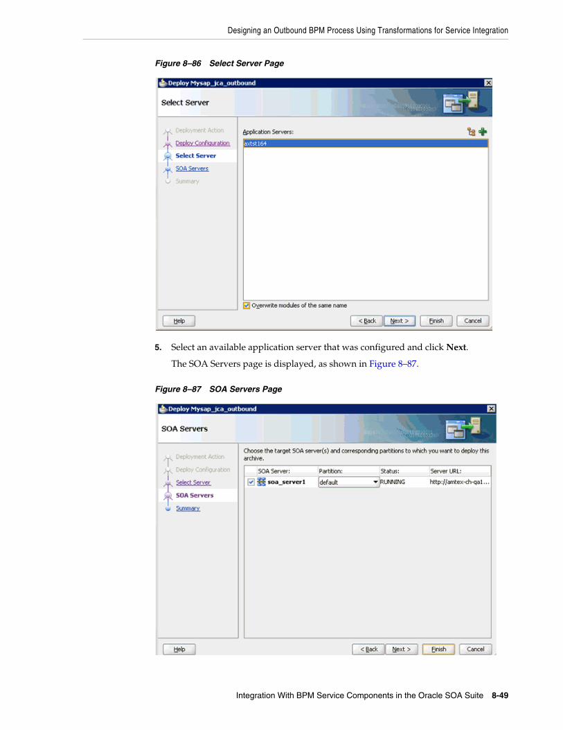
Designing an Outbound BPM Process Using Transformations for Service Integration
Integration With BPM Service Components in the Oracle SOA Suite 8-49
Figure 8–86 Select Server Page
5. Select an available application server that was configured and click Next.
The SOA Servers page is displayed, as shown in Figure 8–87.
Figure 8–87 SOA Servers Page

Designing an Outbound BPM Process Using Transformations for Service Integration
8-50 Oracle Fusion Middleware Application Adapter for SAP R/3 (SAP JCo 3.0) User's Guide for Oracle WebLogic Server
6. Select a target SOA server and click Next.
The Summary page is displayed, as shown in Figure 8–88.
Figure 8–88 Summary Page
7. Review and verify all the available deployment information for your project and click Finish.
The process is deployed successfully, as shown in Figure 8–89.
Figure 8–89 Successful Deployment Message
8.4.4 Invoking the Input XML Document in the Oracle Enterprise Manager ConsolePerform the following steps to invoke the input XML document in the Oracle Enterprise Manager console.
1. Logon to the Oracle Enterprise Manager console, as shown in Figure 8–90.
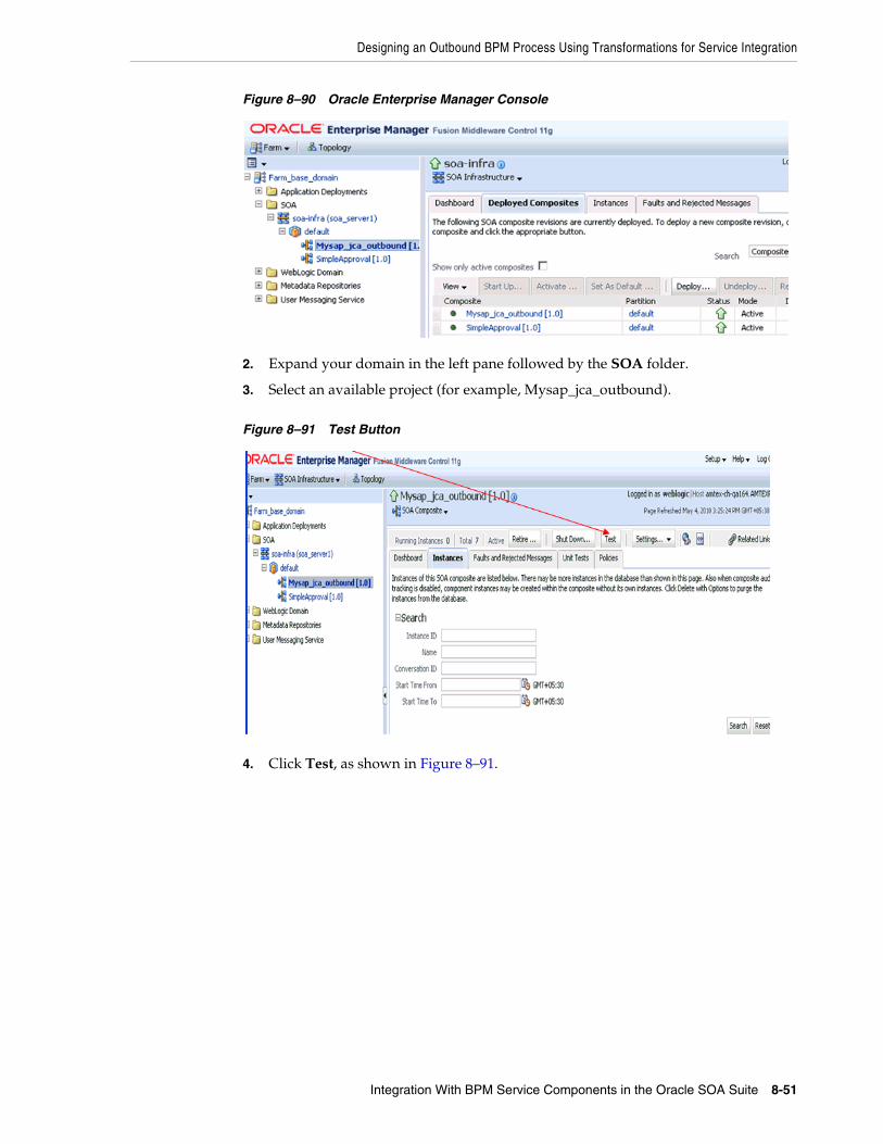
Designing an Outbound BPM Process Using Transformations for Service Integration
Integration With BPM Service Components in the Oracle SOA Suite 8-51
Figure 8–90 Oracle Enterprise Manager Console
2. Expand your domain in the left pane followed by the SOA folder.
3. Select an available project (for example, Mysap_jca_outbound).
Figure 8–91 Test Button
4. Click Test, as shown in Figure 8–91.

Designing an Outbound BPM Process Using Transformations for Service Integration
8-52 Oracle Fusion Middleware Application Adapter for SAP R/3 (SAP JCo 3.0) User's Guide for Oracle WebLogic Server
Figure 8–92 Request Tab
5. Click the Request tab.
6. Provide an appropriate input value in the Value field and click Test Web Service, as shown in Figure 8–92.
A response is received in the Response tab to indicate that invocation was successful in the Oracle Enterprise Manager console, as shown in Figure 8–93.
Figure 8–93 Received Response
7. Navigate to the defined output directory on your file system and open the XML response document that was received, as shown in Figure 8–94.

Designing an Outbound BPM Process Using Transformations for Service Integration
Integration With BPM Service Components in the Oracle SOA Suite 8-53
Figure 8–94 XML Response Document
The XML response document contains the generated output with values. For example:
<?xml version="1.0" encoding="UTF-8" ?><bapi:CompanyCode.GetDetail.Response xmlns:bapi="urn:sap-com:document:sap:business.response" xmlns="urn:sap-com:document:sap:business.response"> <bapi:COMPANYCODE_ADDRESS> <bapi:ADDR_NO>0000000121</bapi:ADDR_NO> <bapi:FORMOFADDR>Firma</bapi:FORMOFADDR> <bapi:NAME>Ides AG</bapi:NAME> <bapi:NAME_2/> <bapi:NAME_3/> <bapi:NAME_4/> <bapi:C_O_NAME/> <bapi:CITY>Frankfurt</bapi:CITY> <bapi:DISTRICT/> <bapi:CITY_NO/> <bapi:POSTL_COD1>60441</bapi:POSTL_COD1> <bapi:POSTL_COD2>60070</bapi:POSTL_COD2> <bapi:POSTL_COD3/> <bapi:PO_BOX>160529</bapi:PO_BOX> <bapi:PO_BOX_CIT/> <bapi:DELIV_DIS/> <bapi:STREET>Lyoner Stern 231</bapi:STREET> <bapi:STREET_NO/> <bapi:STR_ABBR/> <bapi:HOUSE_NO/> <bapi:STR_SUPPL1/> <bapi:STR_SUPPL2/> <bapi:LOCATION/> <bapi:BUILDING/> <bapi:FLOOR/> <bapi:ROOM_NO/> <bapi:COUNTRY>DE</bapi:COUNTRY> <bapi:LANGU>D</bapi:LANGU> <bapi:REGION>06</bapi:REGION> <bapi:SORT1>IDES</bapi:SORT1> <bapi:SORT2/> <bapi:TIME_ZONE>CET</bapi:TIME_ZONE> <bapi:TAXJURCODE/> <bapi:ADR_NOTES/> <bapi:COMM_TYPE/> <bapi:TEL1_NUMBR/> <bapi:TEL1_EXT/> <bapi:FAX_NUMBER/> <bapi:FAX_EXTENS/>

Designing an Outbound BPM Process Using Transformations for Service Integration
8-54 Oracle Fusion Middleware Application Adapter for SAP R/3 (SAP JCo 3.0) User's Guide for Oracle WebLogic Server
</bapi:COMPANYCODE_ADDRESS> <bapi:COMPANYCODE_DETAIL> <bapi:COMP_CODE>1000</bapi:COMP_CODE> <bapi:COMP_NAME>IDES AG</bapi:COMP_NAME> <bapi:CITY>Frankfurt</bapi:CITY> <bapi:COUNTRY>DE</bapi:COUNTRY> <bapi:CURRENCY>EUR</bapi:CURRENCY> <bapi:LANGU>D</bapi:LANGU> <bapi:CHRT_ACCTS>INT</bapi:CHRT_ACCTS> <bapi:FY_VARIANT>K4</bapi:FY_VARIANT> <bapi:VAT_REG_NO>DE123456789</bapi:VAT_REG_NO> <bapi:COMPANY>001000</bapi:COMPANY> <bapi:ADDR_NO>0000000121</bapi:ADDR_NO> <bapi:COUNTRY_ISO>DE</bapi:COUNTRY_ISO> <bapi:CURRENCY_ISO>EUR</bapi:CURRENCY_ISO> <bapi:LANGU_ISO>DE</bapi:LANGU_ISO> </bapi:COMPANYCODE_DETAIL> <bapi:RETURN> <bapi:TYPE/> <bapi:CODE/> <bapi:MESSAGE/> <bapi:LOG_NO/> <bapi:LOG_MSG_NO>000000</bapi:LOG_MSG_NO> <bapi:MESSAGE_V1/> <bapi:MESSAGE_V2/> <bapi:MESSAGE_V3/> <bapi:MESSAGE_V4/> </bapi:RETURN></bapi:CompanyCode.GetDetail.Response>
8.4.5 Workaround for J2CA BPM Processing When Using BAPI or RFC ObjectsWhen a J2CA BPM outbound process for the BusinessArea GetDetail object is created and deployed, the following error is generated in Oracle JDeveloper:
Error: Data Association expression is not valid in node 'ServiceTask': Undefined variable 'businessAreaGetDetail'. Error: Data Association expression is not valid in node 'ServiceTask': Undefined variable 'businessAreaGetDetailResponse'. Error: The transformation in node ServiceTask1 has an invalid target reference: businessAreaGetDetailResponse
This section provides instructions on how to apply a workaround that resolves this issue.
1. Close and then reopen Oracle JDeveloper.
2. Open the composite.xml file from the project folder and double-click the Process component, as shown in Figure 8–95.
Note: This workaround is applicable to Oracle BUG 10078610 - typeloadruntimeexception: bpm-71530 using xsd with attribute group.

Designing an Outbound BPM Process Using Transformations for Service Integration
Integration With BPM Service Components in the Oracle SOA Suite 8-55
Figure 8–95 Process Component
The Process tab is displayed.
3. Double-click the ServiceTask activity, as shown in Figure 8–96.
Figure 8–96 ServiceTask Activity
The Properties - ServiceTask dialog is displayed, as shown in Figure 8–97.

Designing an Outbound BPM Process Using Transformations for Service Integration
8-56 Oracle Fusion Middleware Application Adapter for SAP R/3 (SAP JCo 3.0) User's Guide for Oracle WebLogic Server
Figure 8–97 Properties - ServiceTask Dialog
4. Click the Implementation tab.
5. Uncheck the Use Associations option.
A confirmation message is displayed in the Data Associations dialog, as shown in Figure 8–98.
Figure 8–98 Confirmation Message
6. Click Yes.
You are returned to the Properties - ServiceTask dialog, as shown in Figure 8–99.
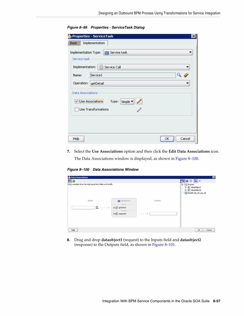
Designing an Outbound BPM Process Using Transformations for Service Integration
Integration With BPM Service Components in the Oracle SOA Suite 8-57
Figure 8–99 Properties - ServiceTask Dialog
7. Select the Use Associations option and then click the Edit Data Associations icon.
The Data Associations window is displayed, as shown in Figure 8–100.
Figure 8–100 Data Associations Window
8. Drag and drop dataobject1 (request) to the Inputs field and dataobject2 (response) to the Outputs field, as shown in Figure 8–101.
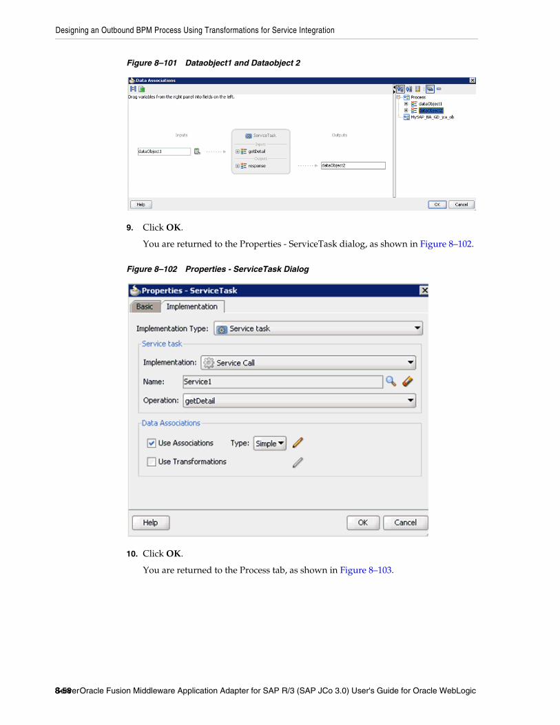
Designing an Outbound BPM Process Using Transformations for Service Integration
8-58 Oracle Fusion Middleware Application Adapter for SAP R/3 (SAP JCo 3.0) User's Guide for Oracle WebLogic Server
Figure 8–101 Dataobject1 and Dataobject 2
9. Click OK.
You are returned to the Properties - ServiceTask dialog, as shown in Figure 8–102.
Figure 8–102 Properties - ServiceTask Dialog
10. Click OK.
You are returned to the Process tab, as shown in Figure 8–103.

Designing an Outbound BPM Process Using Transformations for Service Integration
Integration With BPM Service Components in the Oracle SOA Suite 8-59
Figure 8–103 Process Tab
11. Double-click the ServiceTask1 activity.
The Properties - ServiceTask1 dialog is displayed, as shown in Figure 8–104.
Figure 8–104 Properties - ServiceTask1 Dialog
12. Click the Implementation tab.
13. Uncheck the Use Associations option.
A confirmation message is displayed in the Data Associations dialog, as shown in Figure 8–105.

Designing an Outbound BPM Process Using Transformations for Service Integration
8-60 Oracle Fusion Middleware Application Adapter for SAP R/3 (SAP JCo 3.0) User's Guide for Oracle WebLogic Server
Figure 8–105 Confirmation Message
14. Click Yes.
You are returned to the Properties - ServiceTask1 dialog, as shown in Figure 8–106.
Figure 8–106 Properties - ServiceTask1 Dialog
15. Select the Use Associations option and then click the Edit Data Associations icon.
The Data Associations window is displayed, as shown in Figure 8–107.

Designing an Outbound BPM Process Using Transformations for Service Integration
Integration With BPM Service Components in the Oracle SOA Suite 8-61
Figure 8–107 Data Associations Window
16. Drag and drop dataobject2 (response) to the Inputs field, as shown in Figure 8–108.
Figure 8–108 Dataobject2
17. Click OK.
You are returned to the Properties - ServiceTask1 dialog, as shown in Figure 8–109.

Designing an Outbound BPM Process Using Transformations for Service Integration
8-62 Oracle Fusion Middleware Application Adapter for SAP R/3 (SAP JCo 3.0) User's Guide for Oracle WebLogic Server
Figure 8–109 Properties - ServiceTask1 Dialog
18. Click OK.
You are returned to the Process tab, as shown in Figure 8–110.
Figure 8–110 Process Tab
Notice that no errors or warnings are being indicated.
19. Save the process and then deploy the process.
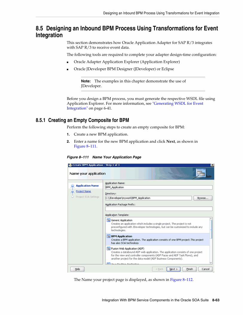
Designing an Inbound BPM Process Using Transformations for Event Integration
Integration With BPM Service Components in the Oracle SOA Suite 8-63
8.5 Designing an Inbound BPM Process Using Transformations for Event Integration
This section demonstrates how Oracle Application Adapter for SAP R/3 integrates with SAP R/3 to receive event data.
The following tools are required to complete your adapter design-time configuration:
■ Oracle Adapter Application Explorer (Application Explorer)
■ Oracle JDeveloper BPM Designer (JDeveloper) or Eclipse
Before you design a BPM process, you must generate the respective WSDL file using Application Explorer. For more information, see "Generating WSDL for Event Integration" on page 6-41.
8.5.1 Creating an Empty Composite for BPMPerform the following steps to create an empty composite for BPM:
1. Create a new BPM application.
2. Enter a name for the new BPM application and click Next, as shown in Figure 8–111.
Figure 8–111 Name Your Application Page
The Name your project page is displayed, as shown in Figure 8–112.
Note: The examples in this chapter demonstrate the use of JDeveloper.

Designing an Inbound BPM Process Using Transformations for Event Integration
8-64 Oracle Fusion Middleware Application Adapter for SAP R/3 (SAP JCo 3.0) User's Guide for Oracle WebLogic Server
Figure 8–112 Name Your Project Page
3. Enter a project name (for example, Mysap_matmas_inbound) and click Next.
The Configure SOA settings page is displayed, as shown in Figure 8–113.
Figure 8–113 Configure SOA Settings Page

Designing an Inbound BPM Process Using Transformations for Event Integration
Integration With BPM Service Components in the Oracle SOA Suite 8-65
4. From the Composite Template list, select Empty Composite and click Finish.
8.5.2 Defining a BPM Inbound ProcessThis section describes how to define a BPM inbound process, which consists of the following stages:
1. Configuring a Third Party Adapter Service Component
2. Configuring an Inbound BPM Process Component
3. Creating a File Adapter for the Write Operation
Configuring a Third Party Adapter Service ComponentPerform the following steps to create a third party adapter service component:
1. Drag and drop the Third Party Adapter component from the Service Adapters pane to the Exposed References pane, as shown in Figure 8–114.
Figure 8–114 Third Party Adapter Component
The Create Third Party Adapter Service dialog is displayed, as shown in Figure 8–115.

Designing an Inbound BPM Process Using Transformations for Event Integration
8-66 Oracle Fusion Middleware Application Adapter for SAP R/3 (SAP JCo 3.0) User's Guide for Oracle WebLogic Server
Figure 8–115 Create Third Party Adapter Service Dialog
2. Enter a name for the third party adapter service.
3. Ensure that Service is selected from the Type list (default).
4. Click the Find existing WSDLs icon, which is located to the right of the WSDL URL field.
The SOA Resource Browser dialog is displayed, as shown in Figure 8–116.

Designing an Inbound BPM Process Using Transformations for Event Integration
Integration With BPM Service Components in the Oracle SOA Suite 8-67
Figure 8–116 SOA Resource Browser Dialog
5. Browse and select an inbound WSDL file from the following directory:
<ADAPTER_HOME>\soa\thirdparty\ApplicationAdapters\wsdls
6. Click OK.
The Localize Files dialog is displayed, as shown in Figure 8–117.
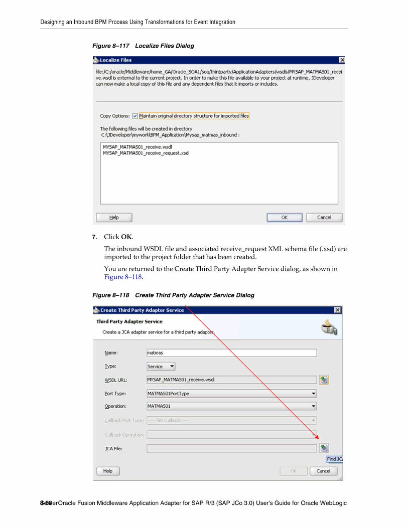
Designing an Inbound BPM Process Using Transformations for Event Integration
8-68 Oracle Fusion Middleware Application Adapter for SAP R/3 (SAP JCo 3.0) User's Guide for Oracle WebLogic Server
Figure 8–117 Localize Files Dialog
7. Click OK.
The inbound WSDL file and associated receive_request XML schema file (.xsd) are imported to the project folder that has been created.
You are returned to the Create Third Party Adapter Service dialog, as shown in Figure 8–118.
Figure 8–118 Create Third Party Adapter Service Dialog

Designing an Inbound BPM Process Using Transformations for Event Integration
Integration With BPM Service Components in the Oracle SOA Suite 8-69
8. Click the Find JCA file icon, which is located to the right of the JCA File field.
The SOA Resource Browser dialog is displayed, as shown in Figure 8–119.
Figure 8–119 SOA Resource Browser Dialog
9. Browse and select the JCA properties file from the following directory:
<ADAPTER_HOME>\soa\thirdparty\ApplicationAdapters\wsdls
10. Click OK.
The Copy File message is displayed, as shown in Figure 8–120.
Figure 8–120 Copy File Confirmaton Message
11. Click Yes.

Designing an Inbound BPM Process Using Transformations for Event Integration
8-70 Oracle Fusion Middleware Application Adapter for SAP R/3 (SAP JCo 3.0) User's Guide for Oracle WebLogic Server
A copy of the JCA properties file is made in the project folder.
You are returned to the Create Third Party Adapter Service dialog, as shown in Figure 8–121.
Figure 8–121 Create Third Party Adapter Service Dialog
12. Click OK.
The third party adapter service component (matmas) is created in the Exposed References pane, as shown in Figure 8–122.
Figure 8–122 Third Party Adapter Service Component
You are now ready to configure an inbound BPM process component.

Designing an Inbound BPM Process Using Transformations for Event Integration
Integration With BPM Service Components in the Oracle SOA Suite 8-71
Configuring an Inbound BPM Process ComponentPerform the following steps to configure an inbound BPM process component:
1. Drag and drop the BPMN Process component from the Service Components pane to the Components pane, as shown in Figure 8–123.
Figure 8–123 BPMN Process Component
The Create BPMN Process dialog is displayed, as shown in Figure 8–124.
Figure 8–124 Create BPMN Process Dialog
2. Select the From Pattern option in the left pane and ensure that Manual Process is selected in the Patterns area.
3. Click Finish.
The BPMN Process component is created, as shown in Figure 8–125.

Designing an Inbound BPM Process Using Transformations for Event Integration
8-72 Oracle Fusion Middleware Application Adapter for SAP R/3 (SAP JCo 3.0) User's Guide for Oracle WebLogic Server
Figure 8–125 BPMN Process Component
4. Double-click the BPMN Process component in the Components pane.
The BPMN process is displayed, as shown in Figure 8–126.
Figure 8–126 BPMN Process
5. Right-click UserTask and select Delete from the menu.
6. Double-click the Start event component, as shown in Figure 8–127.

Designing an Inbound BPM Process Using Transformations for Event Integration
Integration With BPM Service Components in the Oracle SOA Suite 8-73
Figure 8–127 Start Event Component
The Properties - Start dialog is displayed, as shown in Figure 8–128.
Figure 8–128 Properties - Start Dialog
7. Click the Implementation tab, as shown in Figure 8–129.
Figure 8–129 Implementation Tab
8. Select Message from the Implementation Type list, as shown in Figure 8–130.
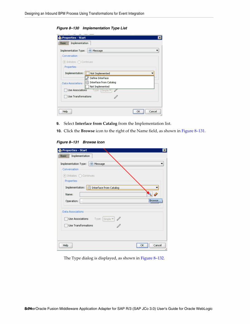
Designing an Inbound BPM Process Using Transformations for Event Integration
8-74 Oracle Fusion Middleware Application Adapter for SAP R/3 (SAP JCo 3.0) User's Guide for Oracle WebLogic Server
Figure 8–130 Implementation Type List
9. Select Interface from Catalog from the Implementation list.
10. Click the Browse icon to the right of the Name field, as shown in Figure 8–131.
Figure 8–131 Browse Icon
The Type dialog is displayed, as shown in Figure 8–132.

Designing an Inbound BPM Process Using Transformations for Event Integration
Integration With BPM Service Components in the Oracle SOA Suite 8-75
Figure 8–132 Type Dialog
11. Select the Third Party Service that has been created and click OK.
You are returned to the Properties - Start dialog, as shown in Figure 8–133.
Figure 8–133 Properties - Start Dialog
12. Select the Use Associations option that is located under Data Associations.
13. Click the Edit Data Associations icon.
The Data Associations dialog is displayed, as shown in Figure 8–134.

Designing an Inbound BPM Process Using Transformations for Event Integration
8-76 Oracle Fusion Middleware Application Adapter for SAP R/3 (SAP JCo 3.0) User's Guide for Oracle WebLogic Server
Figure 8–134 Data Associations Dialog
14. Right-click the Process node in the right pane and select Add.
The Create Data Object dialog is displayed, as shown in Figure 8–135.
Figure 8–135 Create Data Object Dialog
15. Enter a name in the Name field (for example, matmas_inbound) and click Browse more types to the right of the Type field.
The Browse Types dialog is displayed, as shown in Figure 8–136.
Figure 8–136 Browse Types Dialog
16. Select <Component> from the Type list, as shown in Figure 8–137.

Designing an Inbound BPM Process Using Transformations for Event Integration
Integration With BPM Service Components in the Oracle SOA Suite 8-77
Figure 8–137 Type List
17. Select the first component (for example, MATMAS01) and click OK.
You are returned to the Create Data Object dialog, as shown in Figure 8–138.
Figure 8–138 Create Data Object Dialog
18. Click OK.
The Data Object (for example, matmas_inbound) that has been created is displayed under the Process node in the Data Associations dialog, as shown in Figure 8–139.

Designing an Inbound BPM Process Using Transformations for Event Integration
8-78 Oracle Fusion Middleware Application Adapter for SAP R/3 (SAP JCo 3.0) User's Guide for Oracle WebLogic Server
Figure 8–139 Data Associations Dialog
19. Select the matmas_inbound Data Object under the Process node in the right pane and drag it to the field below the Outputs area.
20. Click OK.
You are returned to the Properties - Start dialog, as shown in Figure 8–140.
Figure 8–140 Properties - Start Dialog
21. Click OK.
You are returned to the Process workspace area, as shown in Figure 8–141.

Designing an Inbound BPM Process Using Transformations for Event Integration
Integration With BPM Service Components in the Oracle SOA Suite 8-79
22. Double-click composite.xml in the left pane.
Figure 8–141 Process Workspace Area
23. Click the Save All icon in the menu bar to save the new inbound BPM process component that was configured.
You are now ready to create a File adapter for the write operation.
Creating a File Adapter for the Write OperationPerform the following steps to create a File adapter for the write operation:
1. Drag and drop the File Adapter component from the Service Adapters pane to the External References pane, as shown in Figure 8–142.
Figure 8–142 File Adapter Component
The Adapter Configuration Wizard is displayed, as shown in Figure 8–143.

Designing an Inbound BPM Process Using Transformations for Event Integration
8-80 Oracle Fusion Middleware Application Adapter for SAP R/3 (SAP JCo 3.0) User's Guide for Oracle WebLogic Server
Figure 8–143 Adapter Configuration Wizard
2. Click Next.
The Service Name page is displayed, as shown in Figure 8–144.

Designing an Inbound BPM Process Using Transformations for Event Integration
Integration With BPM Service Components in the Oracle SOA Suite 8-81
Figure 8–144 Service Name Page
3. Type a name for the new File adapter in the Service Name field and click Next.
The Adapter Interface page is displayed, as shown in Figure 8–145.

Designing an Inbound BPM Process Using Transformations for Event Integration
8-82 Oracle Fusion Middleware Application Adapter for SAP R/3 (SAP JCo 3.0) User's Guide for Oracle WebLogic Server
Figure 8–145 Adapter Interface Page
4. Ensure that the Define from operation and schema (specified later) option is selected.
5. Click Next.
The Operation page is displayed, as shown in Figure 8–146.

Designing an Inbound BPM Process Using Transformations for Event Integration
Integration With BPM Service Components in the Oracle SOA Suite 8-83
Figure 8–146 Operation Page
6. Select Write File from the list of Operation Type options and specify an Operation Name (for example, Write).
7. Click Next.
The File Configuration page is displayed, as shown in Figure 8–147.

Designing an Inbound BPM Process Using Transformations for Event Integration
8-84 Oracle Fusion Middleware Application Adapter for SAP R/3 (SAP JCo 3.0) User's Guide for Oracle WebLogic Server
Figure 8–147 File Configuration Page
8. Specify a location on your file system where the output file is written.
9. In the File Naming Convention field, specify a name for the output file.
10. Click Next.
The Messages page is displayed, as shown in Figure 8–148.

Designing an Inbound BPM Process Using Transformations for Event Integration
Integration With BPM Service Components in the Oracle SOA Suite 8-85
Figure 8–148 Messages Page
11. Click Browse, which is located to the right of the URL field.
The Type Chooser dialog is displayed, as shown in Figure 8–149.
Figure 8–149 Type Chooser Dialog
12. Expand Project Schema Files and MYSAP_MATMAS01_receive_request.xsd.

Designing an Inbound BPM Process Using Transformations for Event Integration
8-86 Oracle Fusion Middleware Application Adapter for SAP R/3 (SAP JCo 3.0) User's Guide for Oracle WebLogic Server
13. Select the available schema (for example, MATMAS01).
14. Click OK.
You are returned to the Messages page, as shown in Figure 8–150.
Figure 8–150 Messages Page
15. Click Next.
The Finish page is displayed, as shown in Figure 8–151.

Designing an Inbound BPM Process Using Transformations for Event Integration
Integration With BPM Service Components in the Oracle SOA Suite 8-87
Figure 8–151 Finish Page
16. Click Finish.
The File Adapter service is created in the External References pane, as shown in Figure 8–152.
Figure 8–152 File Adapter Service
17. Double-click the BPMN Process component.
The BPMN process is displayed, as shown in Figure 8–153.

Designing an Inbound BPM Process Using Transformations for Event Integration
8-88 Oracle Fusion Middleware Application Adapter for SAP R/3 (SAP JCo 3.0) User's Guide for Oracle WebLogic Server
Figure 8–153 BPMN Process
18. Click the Activity icon.
19. Drop the Activity icon on the wire between the Start and End event components, as shown in Figure 8–154.
Figure 8–154 Activity Icon
The Properties - Activity dialog is displayed, as shown in Figure 8–155.

Designing an Inbound BPM Process Using Transformations for Event Integration
Integration With BPM Service Components in the Oracle SOA Suite 8-89
Figure 8–155 Properties - Activity Dialog
20. Click the Implementation tab, as shown in Figure 8–156.
Figure 8–156 Implementation Tab
21. Select Service Task from the Implementation Type list, as shown in Figure 8–157.

Designing an Inbound BPM Process Using Transformations for Event Integration
8-90 Oracle Fusion Middleware Application Adapter for SAP R/3 (SAP JCo 3.0) User's Guide for Oracle WebLogic Server
Figure 8–157 Service Task
22. Select Service Call from the Implementation list.
23. Click the Browse icon to the right of the Name field, as shown in Figure 8–158.
Figure 8–158 Browse Icon
The Type dialog is displayed, as shown in Figure 8–159.

Designing an Inbound BPM Process Using Transformations for Event Integration
Integration With BPM Service Components in the Oracle SOA Suite 8-91
Figure 8–159 Type Dialog
24. Select the service for write operation that has been created and click OK.
You are returned to the Properties - Activity dialog, as shown in Figure 8–160.
Figure 8–160 Properties - Activity Dialog
25. Select the Use Transformations option that is located under Data Associations.
26. Click the Edit XSL Transformations icon.
The Transformations dialog is displayed, as shown in Figure 8–161.

Designing an Inbound BPM Process Using Transformations for Event Integration
8-92 Oracle Fusion Middleware Application Adapter for SAP R/3 (SAP JCo 3.0) User's Guide for Oracle WebLogic Server
Figure 8–161 Transformations Dialog
27. Click the Plus icon.
The Transformation dialog is displayed, as shown in Figure 8–162.
Figure 8–162 Transformation Dialog
28. Select the matmas_inbound Data Object that was created from the Sources list.

Designing an Inbound BPM Process Using Transformations for Event Integration
Integration With BPM Service Components in the Oracle SOA Suite 8-93
29. Click the Plus icon so that the Data Object ’matmas_inbound' is added to the Selected Elements area.
Figure 8–163 Target Default Value
30. Accept the default value that is selected in the Target list, as shown in Figure 8–163.

Designing an Inbound BPM Process Using Transformations for Event Integration
8-94 Oracle Fusion Middleware Application Adapter for SAP R/3 (SAP JCo 3.0) User's Guide for Oracle WebLogic Server
Figure 8–164 Transformation Create Field
31. Enter a name (for example, mat) in the Create field and click OK, as shown in Figure 8–164.
You are returned to the Transformations dialog, as shown in Figure 8–165.
Figure 8–165 Transformations Dialog
32. Click OK.
You are returned to the Properties - Activity dialog, as shown in Figure 8–166.

Designing an Inbound BPM Process Using Transformations for Event Integration
Integration With BPM Service Components in the Oracle SOA Suite 8-95
Figure 8–166 Properties - Activity Dialog
33. Click OK.
The mat.xsl tab is displayed, as shown in Figure 8–167.
Figure 8–167 Mat.xsl Tab
34. Automap the Source and Target elements.
The Auto Map Preferences dialog is displayed, as shown in Figure 8–168.

Designing an Inbound BPM Process Using Transformations for Event Integration
8-96 Oracle Fusion Middleware Application Adapter for SAP R/3 (SAP JCo 3.0) User's Guide for Oracle WebLogic Server
Figure 8–168 Auto Map Preferences Dialog
35. Accept the default values and click OK.
The transformation is completed, as shown in Figure 8–169.
Figure 8–169 Completed Transformation
36. Save the transformation.
37. Return to the Process workspace area, as shown in Figure 8–170.

Designing an Inbound BPM Process Using Transformations for Event Integration
Integration With BPM Service Components in the Oracle SOA Suite 8-97
Figure 8–170 Process Workspace Area
The ServiceTask component is created between the Start event component and the End event component.
38. Save the Process and double-click the composite.xml file.
39. Click the Save All icon in the menu bar to save the new inbound BPM process component that was configured.
You are now ready to deploy the inbound BPM process. You can follow the same procedure that is described in "Deploying the BPEL Inbound Process" on page 6-59. For more information on how to trigger events in SAP R/3, see "Triggering an Event in SAP R/3" on page 6-65.

Designing an Inbound BPM Process Using Transformations for Event Integration
8-98 Oracle Fusion Middleware Application Adapter for SAP R/3 (SAP JCo 3.0) User's Guide for Oracle WebLogic Server

9
Configuring Outbound and Inbound Processing Using Oracle Service Bus 9-1
9 Configuring Outbound and InboundProcessing Using Oracle Service Bus
Oracle Application Adapter for SAP R/3 integrates seamlessly with Oracle Service Bus (OSB) to facilitate Web service integration. OSB is based on the Service-Oriented Architecture (SOA). It consumes adapter services exposed as Web Service Definition Language (WSDL) documents.
This chapter contains the following topics:
■ Section 9.1, "Overview of Application Adapter Integration with Oracle Service Bus"
■ Section 9.2, "Configuring Outbound Processing Using Oracle Service Bus (J2CA Configuration)"
■ Section 9.3, "Configuring Inbound Processing Using Oracle Service Bus (J2CA Configuration)"
■ Section 9.4, "Configuring Outbound Processing Using Oracle Service Bus (BSE Configuration)"
9.1 Overview of Application Adapter Integration with Oracle Service BusTo integrate with Oracle Service Bus (OSB), Oracle Application Adapter for SAP R/3 must be deployed in the same Oracle WebLogic Server as OSB. The underlying adapter services must be exposed as WSDL files, which are generated during design time in Oracle Adapter Application Explorer (Application Explorer) for both request-response (outbound) and event notification (inbound) services of the adapter.
9.2 Configuring Outbound Processing Using Oracle Service Bus (J2CA Configuration)
This section describes how to configure outbound processing using Oracle Service Bus for J2CA configurations.
This section includes the following topics:
■ Section 9.2.1, "Starting Oracle Service Bus and Creating Project Folders"
■ Section 9.2.2, "Setting the Class Path for Application Explorer to Integrate With Oracle Service Bus"
■ Section 9.2.3, "Publishing a WSDL From Application Explorer to Oracle Service Bus"
■ Section 9.2.4, "Configuring a File Type Business Service"

Configuring Outbound Processing Using Oracle Service Bus (J2CA Configuration)
9-2 Oracle Fusion Middleware Application Adapter for SAP R/3 (SAP JCo 3.0) User's Guide for Oracle WebLogic Server
■ Section 9.2.5, "Configuring a Proxy Service"
■ Section 9.2.6, "Configuring a Pipeline"
9.2.1 Starting Oracle Service Bus and Creating Project FoldersThis section describes how to start Oracle Service Bus (OSB) and create project folders.
Perform the following steps to start Oracle Service Bus and create project folders:
1. Start the Oracle WebLogic Server for the Oracle WebLogic Server domain that you have configured.
2. Open the Oracle Service Bus Console in a Web browser by entering the following URL:
http://hostname:port/sbconsole
Where hostname is the name of the machine where Oracle WebLogic Server is running and port is the port for the domain you are using. The port for the default domain is 7001.
The Oracle Service Bus Console logon page is displayed.
3. Log on to the Oracle Service Bus Console using a valid user name and password.
The Oracle Service Bus Console home page is displayed, as shown in Figure 9–1.
Note: If you are using Oracle Application Adapter for SAP R/3 (SAP JCo 3.0) with OSB on 64-bit machines, you must add the d64 flag with the JAVA options in the startWebLogic.sh file, which is located in the following directory:
<OSB_Home>\user_projects\domains\base_domain\bin
For example:
JAVA_OPTIONS="${SAVE_JAVA_OPTIONS} -Dfile.encoding=ISO8859_1 -d64"
The Oracle WebLogic Server must be started only after this change has been made.

Configuring Outbound Processing Using Oracle Service Bus (J2CA Configuration)
Configuring Outbound and Inbound Processing Using Oracle Service Bus 9-3
Figure 9–1 Oracle Service Bus Console Home Page
4. Click Create in the Change Center area to start a new Oracle Service Bus session, as shown in Figure 9–2.
Figure 9–2 Change Center
5. Click Project Explorer in the left pane, as shown in Figure 9–3.
Figure 9–3 Project Explorer
The Project Explorer page is displayed, as shown in Figure 9–4.

Configuring Outbound Processing Using Oracle Service Bus (J2CA Configuration)
9-4 Oracle Fusion Middleware Application Adapter for SAP R/3 (SAP JCo 3.0) User's Guide for Oracle WebLogic Server
Figure 9–4 Project Explorer Page
6. Provide a valid name for the new project (for example, SAP_Project) and click Add Project.
The new project is successfully created and listed in the left pane.
7. Click the new project node in the left pane.
The project page is displayed, as shown in Figure 9–5.
Figure 9–5 Project Page
8. In the Enter New Folder Name field, type Business Service and click Add Folder.
9. In the Enter New Folder Name field, type Proxy Service and click Add Folder.
10. In the Enter New Folder Name field, type wsdls and click Add Folder.
The Business Service, Proxy Service, and wsdls folders are listed in the left pane below the new SAP_Project node, as shown in Figure 9–6.
Figure 9–6 SAP_Project Node

Configuring Outbound Processing Using Oracle Service Bus (J2CA Configuration)
Configuring Outbound and Inbound Processing Using Oracle Service Bus 9-5
9.2.2 Setting the Class Path for Application Explorer to Integrate With Oracle Service Bus
Before starting and using Application Explorer to publish a WSDL directly to the Oracle Service Bus (OSB) Console (project/folder), OSB users must perform the following steps:
1. Open the command prompt window.
2. Navigate to the following directory:
<OSB_Home>\user_projects\domains\base_domain\bin
3. Execute setDomainEnv.cmd (Windows) or . ./setDomainEnv.sh (UNIX/Linux).
This command sets the class path for Application Explorer to access the Oracle WebLogic Server APIs to publish the WSDLs to the OSB Console.
4. Do not close the command prompt window.
5. Navigate to the following directory:
<OSB_Home>\3rdparty\ApplicationAdapters\tools\iwae\bin
6. Execute ae.bat (Windows) or iwae.sh (UNIX/Linux) to start Application Explorer.
You are now ready to publish WSDLs from Application Explorer to the OSB Console.
9.2.3 Publishing a WSDL From Application Explorer to Oracle Service BusPerform the following steps to publish a WSDL from Application Explorer to Oracle Service Bus:
1. Start Application Explorer, connect to a J2CA configuration, and connect to a SAP R/3 target.
For more information, see Chapter 4, "Configuring Oracle Application Adapter for SAP R/3".
2. Expand Business Object Repository, Financial Accounting, and then CompanyCode.
3. Right-click the GetDetail method and select Create Outbound JCA Service(Request/Response) from the menu, as shown in Figure 9–7.

Configuring Outbound Processing Using Oracle Service Bus (J2CA Configuration)
9-6 Oracle Fusion Middleware Application Adapter for SAP R/3 (SAP JCo 3.0) User's Guide for Oracle WebLogic Server
Figure 9–7 Create Outbound JCA Service (Request/Response) Option
The Export WSDL dialog is displayed, as shown in Figure 9–8.
Figure 9–8 Export WSDL Dialog

Configuring Outbound Processing Using Oracle Service Bus (J2CA Configuration)
Configuring Outbound and Inbound Processing Using Oracle Service Bus 9-7
4. In the Name field, a default file name for the WSDL file is provided. You can accept the default or provide your own.
5. Select the Export to OSB option.
6. In the Location field, enter the folder name in Oracle Service Bus where you want to publish the WSDL document.
The location is composed of an Oracle Service Bus project name and optionally, one or more folder names. The project name and any folder names must be separated by a forward slash character “/”.
7. In the Host field, enter the name of the machine where Oracle Service Bus is installed.
8. In the Port field, enter the port that is being used by Oracle Service Bus.
9. In the User field, enter your username to access Oracle Service Bus.
10. In the Password field, enter your password to access Oracle Service Bus.
11. Click OK.
The WSDL is published to the location specified in the Export WSDL dialog and is now available for use with a Business Service or Proxy Service in Oracle Service Bus.
12. Open the Oracle Service Bus Console and select the created WSDL folder in the left pane (for example, wsdls), as shown in Figure 9–9.
Figure 9–9 Created WSDL Folder
13. Ensure that the exported WSDL is listed, as shown in Figure 9–10.
Figure 9–10 Exported WSDL
14. Click the icon that corresponds to the exported WSDL in the Actions column.
The Generate WSDL and Service page is displayed, as shown in Figure 9–11.

Configuring Outbound Processing Using Oracle Service Bus (J2CA Configuration)
9-8 Oracle Fusion Middleware Application Adapter for SAP R/3 (SAP JCo 3.0) User's Guide for Oracle WebLogic Server
Figure 9–11 Generate WSDL and Service Page
15. Provide a new WSDL name and a new service name in the corresponding fields, as shown in Figure 9–12.
Figure 9–12 WSDL Name and Service Name
16. In the Location area, select an available project and the sub-folder that is designated for Business Services.
17. Click Generate.

Configuring Outbound Processing Using Oracle Service Bus (J2CA Configuration)
Configuring Outbound and Inbound Processing Using Oracle Service Bus 9-9
If the WSDL and Service resources are successfully created, then the following message is displayed, as shown in Figure 9–13.
Figure 9–13 Successful Creation Message
9.2.4 Configuring a File Type Business ServicePerform the following steps to configure a File type Business Service:
1. Select the Business Service folder you created in the left pane, as shown in Figure 9–14.
Figure 9–14 Business Service Folder
2. In the right pane, select Business Service from the Create Resource menu, as shown in Figure 9–15.
Figure 9–15 Business Service
The General Configuration page is displayed, as shown in Figure 9–16.

Configuring Outbound Processing Using Oracle Service Bus (J2CA Configuration)
9-10 Oracle Fusion Middleware Application Adapter for SAP R/3 (SAP JCo 3.0) User's Guide for Oracle WebLogic Server
Figure 9–16 General Configuration Page
3. Provide a name for the new Business Service and select Messaging Service from the Service Type area.
4. Click Next.
The Message Type Configuration page is displayed, as shown in Figure 9–17.
Figure 9–17 Message Type Configuration Page
5. Select XML as the Request Message Type and None as the Response Message Type.
6. Click Next.

Configuring Outbound Processing Using Oracle Service Bus (J2CA Configuration)
Configuring Outbound and Inbound Processing Using Oracle Service Bus 9-11
The Transport Configuration page is displayed, as shown in Figure 9–18.
Figure 9–18 Transport Configuration Page
7. Select file from the Protocol list.
8. Enter the path to a destination folder on your file system in the Endpoint URI field and click Add.
9. Click Next, as shown in Figure 9–19.
Figure 9–19 Transport Configuration Page
The FILE Transport Configuration page is displayed, as shown in Figure 9–20.

Configuring Outbound Processing Using Oracle Service Bus (J2CA Configuration)
9-12 Oracle Fusion Middleware Application Adapter for SAP R/3 (SAP JCo 3.0) User's Guide for Oracle WebLogic Server
Figure 9–20 FILE Transport Configuration Page
10. Enter the prefix and suffix for the output file to be received and click Next.
The Message Handling and Advanced Settings page is displayed, as shown in Figure 9–21.
Figure 9–21 Message Handling and Advanced Settings Page
11. Click Next.
The following Summary page is displayed, as shown in Figure 9–22.

Configuring Outbound Processing Using Oracle Service Bus (J2CA Configuration)
Configuring Outbound and Inbound Processing Using Oracle Service Bus 9-13
Figure 9–22 Summary Page
12. Review all the information for your Business Service and click Save.
13. Check if the success message is displayed and click Activate in the Change Center, as shown in Figure 9–23.
Figure 9–23 Success Message
The Activate Session page is displayed, as shown in Figure 9–24.

Configuring Outbound Processing Using Oracle Service Bus (J2CA Configuration)
9-14 Oracle Fusion Middleware Application Adapter for SAP R/3 (SAP JCo 3.0) User's Guide for Oracle WebLogic Server
Figure 9–24 Activate Session Page
14. Click Submit.
15. Check if the View Configuration Changes page is displayed, as shown in Figure 9–25.
Figure 9–25 View Configuration Changes Page
9.2.5 Configuring a Proxy ServicePerform the following steps to configure a Proxy Service:
1. Select the Proxy Service folder you created in the left pane, as shown in Figure 9–26.

Configuring Outbound Processing Using Oracle Service Bus (J2CA Configuration)
Configuring Outbound and Inbound Processing Using Oracle Service Bus 9-15
Figure 9–26 Proxy Service Folder
2. In the right pane, select Proxy Service from the Create Resource menu.
The General Configuration page is displayed, as shown in Figure 9–27.
Figure 9–27 General Configuration Page
3. Provide a name for the Proxy Service and from the Service Type area select Any XML Service.
4. Click Next, as shown in Figure 9–28.

Configuring Outbound Processing Using Oracle Service Bus (J2CA Configuration)
9-16 Oracle Fusion Middleware Application Adapter for SAP R/3 (SAP JCo 3.0) User's Guide for Oracle WebLogic Server
Figure 9–28 Transport Configuration Page
5. Select file from the Protocol list.
6. Enter the path to an input folder on your file system in the Endpoint URI field.
7. Click Next, as shown in Figure 9–29.
Figure 9–29 FILE Transport Configuration Page
8. Provide any folder locations on your file system for the Stage Directory and Error Directory fields.
9. Click Next, as shown in Figure 9–30.

Configuring Outbound Processing Using Oracle Service Bus (J2CA Configuration)
Configuring Outbound and Inbound Processing Using Oracle Service Bus 9-17
Figure 9–30 Message Handling Page
10. Accept the default values and click Next.
The following Summary page is displayed, as shown in Figure 9–31.
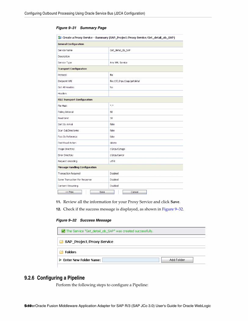
Configuring Outbound Processing Using Oracle Service Bus (J2CA Configuration)
9-18 Oracle Fusion Middleware Application Adapter for SAP R/3 (SAP JCo 3.0) User's Guide for Oracle WebLogic Server
Figure 9–31 Summary Page
11. Review all the information for your Proxy Service and click Save.
12. Check if the success message is displayed, as shown in Figure 9–32.
Figure 9–32 Success Message
9.2.6 Configuring a PipelinePerform the following steps to configure a Pipeline:
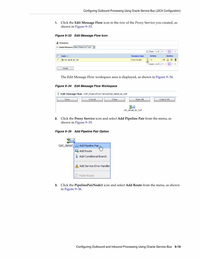
Configuring Outbound Processing Using Oracle Service Bus (J2CA Configuration)
Configuring Outbound and Inbound Processing Using Oracle Service Bus 9-19
1. Click the Edit Message Flow icon in the row of the Proxy Service you created, as shown in Figure 9–33.
Figure 9–33 Edit Message Flow Icon
The Edit Message Flow workspace area is displayed, as shown in Figure 9–34.
Figure 9–34 Edit Message Flow Workspace
2. Click the Proxy Service icon and select Add Pipeline Pair from the menu, as shown in Figure 9–35.
Figure 9–35 Add Pipeline Pair Option
3. Click the PipelinePairNode1 icon and select Add Route from the menu, as shown in Figure 9–36.

Configuring Outbound Processing Using Oracle Service Bus (J2CA Configuration)
9-20 Oracle Fusion Middleware Application Adapter for SAP R/3 (SAP JCo 3.0) User's Guide for Oracle WebLogic Server
Figure 9–36 Add Route Option
The RouteNode1 icon is added below the Request Pipeline icon, as shown in Figure 9–37.
Figure 9–37 RouteNode1 Icon
4. Click the RouteNode1 icon and select Edit Route from the menu.
The Edit Stage Configuration workspace area is displayed, as shown in Figure 9–38.

Configuring Outbound Processing Using Oracle Service Bus (J2CA Configuration)
Configuring Outbound and Inbound Processing Using Oracle Service Bus 9-21
Figure 9–38 Edit Stage Configuration Workspace Area
5. Click Add an Action, select Communication from the menu, and click Routing.
Figure 9–39 Edit Stage Configuration Workspace Area
6. Click <Service>, as shown in Figure 9–39.
The Select Service dialog is displayed, as shown in Figure 9–40.
Figure 9–40 Select Service Dialog

Configuring Outbound Processing Using Oracle Service Bus (J2CA Configuration)
9-22 Oracle Fusion Middleware Application Adapter for SAP R/3 (SAP JCo 3.0) User's Guide for Oracle WebLogic Server
7. Select the WSDL type Business Service configured for SAP R/3 and click Submit.
You are returned to the Edit Stage Configuration workspace area, as shown in Figure 9–41.
Figure 9–41 Edit Stage Configuration Workspace Area
8. Select the name of the SAP R/3 business object (for example, GetDetail) as the operational attribute from the list, as shown in Figure 9–42.
Figure 9–42 Business Object
9. Click Save.

Configuring Outbound Processing Using Oracle Service Bus (J2CA Configuration)
Configuring Outbound and Inbound Processing Using Oracle Service Bus 9-23
Figure 9–43 Add Stage Option
10. Click the Response Pipeline icon and select Add Stage from the menu, as shown in Figure 9–43.
The Stage1 icon is added below the Response Pipeline icon.
Figure 9–44 Edit Stage Option
11. Click the Stage1 icon and select Edit Stage from the menu, as shown in Figure 9–44.

Configuring Outbound Processing Using Oracle Service Bus (J2CA Configuration)
9-24 Oracle Fusion Middleware Application Adapter for SAP R/3 (SAP JCo 3.0) User's Guide for Oracle WebLogic Server
The Edit Stage Configuration workspace area is displayed, as shown in Figure 9–45.
Figure 9–45 Edit Stage Configuration Workspace Area
12. Click Add an Action, select Communication from the menu, and click Publish.
Figure 9–46 Edit Stage Configuration Workspace Area
13. Click <Service>, as shown in Figure 9–46.
The Select Service dialog is displayed, as shown in Figure 9–47.

Configuring Outbound Processing Using Oracle Service Bus (J2CA Configuration)
Configuring Outbound and Inbound Processing Using Oracle Service Bus 9-25
Figure 9–47 Select Service Dialog
14. Select a File type Business Service and click Submit.
You are returned to the Edit Stage Configuration workspace area.
Figure 9–48 Save
15. Click Save, as shown in Figure 9–48.
You are returned to the Edit Message Flow workspace area, as shown in Figure 9–49.

Configuring Outbound Processing Using Oracle Service Bus (J2CA Configuration)
9-26 Oracle Fusion Middleware Application Adapter for SAP R/3 (SAP JCo 3.0) User's Guide for Oracle WebLogic Server
Figure 9–49 Edit Message Flow Workspace Area
16. Click Save.
Figure 9–50 Successful Update Message
17. Check if the success message is displayed and click Activate in the Change Center, as shown in Figure 9–50.
The Activate Session page is displayed, as shown in Figure 9–51.

Configuring Outbound Processing Using Oracle Service Bus (J2CA Configuration)
Configuring Outbound and Inbound Processing Using Oracle Service Bus 9-27
Figure 9–51 Activate Session Page
18. Click Submit.
19. Check if the View Configuration Changes page is displayed, as shown in Figure 9–52.
Figure 9–52 View Configuration Changes Page
20. Copy and paste an input XML file in the input folder you have configured, as shown in Figure 9–53.
Figure 9–53 Input XML File
21. Output is received in the configured output location.

Configuring Inbound Processing Using Oracle Service Bus (J2CA Configuration)
9-28 Oracle Fusion Middleware Application Adapter for SAP R/3 (SAP JCo 3.0) User's Guide for Oracle WebLogic Server
9.3 Configuring Inbound Processing Using Oracle Service Bus (J2CA Configuration)
This section describes how to configure inbound processing using Oracle Service Bus for J2CA configurations.
This section includes the following topics:
■ Section 9.3.1, "Starting Oracle Service Bus and Creating Project Folders"
■ Section 9.3.2, "Setting the Class Path for Application Explorer to Integrate With Oracle Service Bus"
■ Section 9.3.3, "Publishing a WSDL From Application Explorer to Oracle Service Bus"
■ Section 9.3.4, "Configuring a File Type Business Service"
■ Section 9.3.5, "Configuring a Pipeline"
9.3.1 Starting Oracle Service Bus and Creating Project FoldersThis section describes how to start Oracle Service Bus (OSB) and create project folders.
Perform the following steps to start Oracle Service Bus and create project folders:
1. Start the Oracle WebLogic Server for the Oracle WebLogic Server domain that you have configured.
2. Open the Oracle Service Bus Console in a Web browser by entering the following URL:
http://hostname:port/sbconsole
Where hostname is the name of the machine where Oracle WebLogic Server is running and port is the port for the domain you are using. The port for the default domain is 7001.
The Oracle Service Bus Console logon page is displayed.
3. Log on to the Oracle Service Bus Console using a valid user name and password.
The Oracle Service Bus Console home page is displayed, as shown in Figure 9–54.
Note: If you are using Oracle Application Adapter for SAP R/3 (SAP JCo 3.0) with OSB on 64-bit machines, you must add the d64 flag with the JAVA options in the startWebLogic.sh file, which is located in the following directory:
<OSB_Home>\user_projects\domains\base_domain\bin
For example:
JAVA_OPTIONS="${SAVE_JAVA_OPTIONS} -Dfile.encoding=ISO8859_1 -d64"
The Oracle WebLogic Server must be started only after this change has been made.

Configuring Inbound Processing Using Oracle Service Bus (J2CA Configuration)
Configuring Outbound and Inbound Processing Using Oracle Service Bus 9-29
Figure 9–54 Oracle Service Bus Console
4. Click Create in the Change Center area to start a new Oracle Service Bus session, as shown in Figure 9–55.
Figure 9–55 Change Center
5. Click Project Explorer in the left pane, as shown in Figure 9–56.
Figure 9–56 Project Explorer Option
The Project Explorer page is displayed, as shown in Figure 9–57.

Configuring Inbound Processing Using Oracle Service Bus (J2CA Configuration)
9-30 Oracle Fusion Middleware Application Adapter for SAP R/3 (SAP JCo 3.0) User's Guide for Oracle WebLogic Server
Figure 9–57 Project Explorer Page
6. Provide a valid name for the new project and click Add Project.
The project is successfully created and listed.
7. Click on the created project.
The project page is displayed, as shown in Figure 9–58.
Figure 9–58 Project Page
8. In the Enter New Folder Name field, type Business Service and click Add Folder.
9. In the Enter New Folder Name field, type Proxy Service and click Add Folder.
10. In the Enter New Folder Name field, type wsdls and click Add Folder.
The Business Service, Proxy Service, and wsdls folders are listed in the left pane below the project node., as shown in Figure 9–59
Figure 9–59 SAP_Project Node
Configuring Inbound Processing Using Oracle Service Bus (J2CA Configuration)
Configuring Outbound and Inbound Processing Using Oracle Service Bus 9-31
9.3.2 Setting the Class Path for Application Explorer to Integrate With Oracle Service Bus
Before starting and using Application Explorer to publish a WSDL directly to the Oracle Service Bus (OSB) Console (project/folder), OSB users must perform the following steps:
1. Open the command prompt window.
2. Navigate to the following directory:
<OSB_Home>\user_projects\domains\base_domain\bin
3. Execute setDomainEnv.cmd (Windows) or . ./setDomainEnv.sh (UNIX/Linux).
This command sets the class path for Application Explorer to access the Oracle WebLogic Server APIs to publish the WSDLs to the OSB Console.
4. Do not close the command prompt window.
5. Navigate to the following directory:
<OSB_Home>\3rdparty\ApplicationAdapters\tools\iwae\bin
6. Execute ae.bat (Windows) or iwae.sh (UNIX/Linux) to start Application Explorer.
You are now ready to publish WSDLs from Application Explorer to the OSB Console.
9.3.3 Publishing a WSDL From Application Explorer to Oracle Service BusPerform the following steps to publish a WSDL from Application Explorer to Oracle Service Bus:
1. Start Application Explorer, connect to a J2CA configuration, and connect to a SAP R/3 target.
For more information, see Chapter 4, "Configuring Oracle Application Adapter for SAP R/3".
2. Expand the Events node.
3. Right-click the Channels node for MySAP and select Add Channel from the menu, as shown in Figure 9–60.

Configuring Inbound Processing Using Oracle Service Bus (J2CA Configuration)
9-32 Oracle Fusion Middleware Application Adapter for SAP R/3 (SAP JCo 3.0) User's Guide for Oracle WebLogic Server
Figure 9–60 Add Channel Option
The Add Channel dialog is displayed, as shown in Figure 9–61.
Figure 9–61 Add Channel Dialog
The Application Server dialog is displayed, as shown in Figure 9–62.

Configuring Inbound Processing Using Oracle Service Bus (J2CA Configuration)
Configuring Outbound and Inbound Processing Using Oracle Service Bus 9-33
Figure 9–62 Application Server Dialog
4. Provide the required connection information for your SAP R/3 system and click OK.
The new channel is added below the Channels node.
5. Expand the Adapters node and then the MySAP node.
6. Expand the ALE (IDOCs) node and then the MATMAS -- Material node.
Figure 9–63 Create Inbound JCA Service(Event) Option
7. Right-click MATMAS01 and select Create Inbound JCA Service(Event) from the menu, as shown in Figure 9–63.
The Export WSDL dialog is displayed, as shown in Figure 9–64.

Configuring Inbound Processing Using Oracle Service Bus (J2CA Configuration)
9-34 Oracle Fusion Middleware Application Adapter for SAP R/3 (SAP JCo 3.0) User's Guide for Oracle WebLogic Server
Figure 9–64 Export WSDL Dialog
8. In the Name field, a default file name for the WSDL file is provided. You can accept the default or provide your own.
9. From the Channel list, select the channel you created for this inbound service.
10. Three check boxes for Root, Namespace, and Schema validation are also available. Selection of multiple validation options is allowed.
11. Select the Export to OSB option.
12. In the Location field, enter the folder name in Oracle Service Bus where you want to publish the WSDL document.
The location is composed of an Oracle Service Bus project name and optionally, one or more folder names. The project name and any folder names must be separated by a forward slash character “/”.
13. In the Host field, enter the name of the machine where Oracle Service Bus is installed.
14. In the Port field, enter the port that is being used by Oracle Service Bus.
15. In the User field, enter your username to access Oracle Service Bus.
16. In the Password field, enter your password to access Oracle Service Bus.
17. Click OK.
The inbound WSDL is published to the location specified in the Export WSDL dialog and is now available for use with a Business Service or Proxy Service in Oracle Service Bus.

Configuring Inbound Processing Using Oracle Service Bus (J2CA Configuration)
Configuring Outbound and Inbound Processing Using Oracle Service Bus 9-35
18. Open the Oracle Service Bus Console and select the created WSDL folder in the left pane (for example, wsdls), as shown in Figure 9–65.
Figure 9–65 Created WSDL Folder
19. Ensure that the exported WSDL is listed, as shown in Figure 9–66.
Figure 9–66 Exported WSDL
20. Click the icon that corresponds to the exported WSDL in the Actions column.
The Generate WSDL and Service page is displayed, as shown in Figure 9–67.

Configuring Inbound Processing Using Oracle Service Bus (J2CA Configuration)
9-36 Oracle Fusion Middleware Application Adapter for SAP R/3 (SAP JCo 3.0) User's Guide for Oracle WebLogic Server
Figure 9–67 Generate WSDL and Service Page
21. Provide a new WSDL name and a new service name in the corresponding fields.
22. In the Location area, select an available project and the sub-folder that is designated for Proxy Services.
23. Click Generate.
If the WSDL and Service resources are successfully created, then the following message is displayed, as shown in Figure 9–68.
Figure 9–68 Success Message
24. Click Proxy Service under Project Explorer and check if the generated WSDL and Proxy Service are listed, as shown in Figure 9–69.
Figure 9–69 Generated WSDL

Configuring Inbound Processing Using Oracle Service Bus (J2CA Configuration)
Configuring Outbound and Inbound Processing Using Oracle Service Bus 9-37
9.3.4 Configuring a File Type Business ServicePerform the following steps to configure a File type Business Service:
1. Select the Business Service folder you created in the left pane, as shown in Figure 9–70.
Figure 9–70 Business Service Folder
2. In the right pane, select Business Service from the Create Resource menu, as shown in Figure 9–71.
Figure 9–71 Business Service
The General Configuration page is displayed, as shown in Figure 9–72.

Configuring Inbound Processing Using Oracle Service Bus (J2CA Configuration)
9-38 Oracle Fusion Middleware Application Adapter for SAP R/3 (SAP JCo 3.0) User's Guide for Oracle WebLogic Server
Figure 9–72 General Configuration Page
3. Provide a name for the Business Service and from the Service Type area select Messaging Service.
4. Click Next.
The Message Type Configuration page is displayed, as shown in Figure 9–73.
Figure 9–73 Message Type Configuration Page

Configuring Inbound Processing Using Oracle Service Bus (J2CA Configuration)
Configuring Outbound and Inbound Processing Using Oracle Service Bus 9-39
5. Select XML as the Request Message Type and None as the Response Message Type.
6. Click Next.
The Transport Configuration page is displayed, as shown in Figure 9–74.
Figure 9–74 Transport Configuration Page
7. Select file from the Protocol list.
8. Enter the path to a destination folder on your file system in the Endpoint URI field and click Add.
9. Click Next.
The FILE Transport Configuration page is displayed, as shown in Figure 9–75.
Figure 9–75 FILE Transport Configuration Page
10. Enter the prefix and suffix for the output file to be received and click Next.
The Message Handling and Advanced Settings page is displayed, as shown in Figure 9–76.

Configuring Inbound Processing Using Oracle Service Bus (J2CA Configuration)
9-40 Oracle Fusion Middleware Application Adapter for SAP R/3 (SAP JCo 3.0) User's Guide for Oracle WebLogic Server
Figure 9–76 Message Handling and Advanced Settings Page
11. Click Next.
The following Summary page is displayed, as shown in Figure 9–77.
Figure 9–77 Summary Page
12. Review all the information for your Business Service and click Save.
13. Check if the success message is displayed and click Activate in the Change Center, as shown in Figure 9–78.

Configuring Inbound Processing Using Oracle Service Bus (J2CA Configuration)
Configuring Outbound and Inbound Processing Using Oracle Service Bus 9-41
Figure 9–78 Change Center
The Activate Session page is displayed, as shown in Figure 9–79.
Figure 9–79 Activate Session Page
14. Click Submit.
15. Check if the View Configuration Changes page is displayed, as shown in Figure 9–80.
Figure 9–80 View Configuration Changes Page

Configuring Inbound Processing Using Oracle Service Bus (J2CA Configuration)
9-42 Oracle Fusion Middleware Application Adapter for SAP R/3 (SAP JCo 3.0) User's Guide for Oracle WebLogic Server
9.3.5 Configuring a PipelinePerform the following steps to configure a Pipeline:
1. Click the Edit Message Flow icon in the row of the Proxy Service you created, as shown in Figure 9–81.
Figure 9–81 Edit Message Flow Icon
The Edit Message Flow workspace area is displayed, as shown in Figure 9–82.
Figure 9–82 Edit Message Flow Workspace Area
2. Click the displayed Proxy service icon and select Add Route from the menu.
The RouteNode1 icon is added below the Request Pipeline icon.

Configuring Inbound Processing Using Oracle Service Bus (J2CA Configuration)
Configuring Outbound and Inbound Processing Using Oracle Service Bus 9-43
Figure 9–83 Edit Route Option
3. Click the RouteNode1 icon and select Edit Route from the menu, as shown in Figure 9–83.
The Edit Stage Configuration workspace area is displayed, as shown in Figure 9–84.
Figure 9–84 Edit Stage Configuration Workspace Area
4. Click Add an Action, select Communication from the menu, and click Routing, as shown in Figure 9–85.

Configuring Inbound Processing Using Oracle Service Bus (J2CA Configuration)
9-44 Oracle Fusion Middleware Application Adapter for SAP R/3 (SAP JCo 3.0) User's Guide for Oracle WebLogic Server
Figure 9–85 Edit Stage Configuration Page
5. Click <Service>.
The Select Service dialog is displayed, as shown in Figure 9–86.
Figure 9–86 Select Service Dialog
6. Select a File type Business Service and click Submit.
You are returned to the Edit Stage Configuration workspace area, as shown in Figure 9–87.

Configuring Inbound Processing Using Oracle Service Bus (J2CA Configuration)
Configuring Outbound and Inbound Processing Using Oracle Service Bus 9-45
Figure 9–87 Edit Stage Configuration Workspace Area
7. Click Save.
You are returned to the Edit Message Flow workspace area, as shown in Figure 9–88.
Figure 9–88 Edit Message Flow Workspace Area
8. Click Save.
Figure 9–89 Successful Update Message
9. Check if the success message is displayed and click Activate in the Change Center, as shown in Figure 9–89.

Configuring Outbound Processing Using Oracle Service Bus (BSE Configuration)
9-46 Oracle Fusion Middleware Application Adapter for SAP R/3 (SAP JCo 3.0) User's Guide for Oracle WebLogic Server
The Activate Session page is displayed, as shown in Figure 9–90.
Figure 9–90 Activate Session Page
10. Click Submit.
11. Check if the View Configuration Changes page is displayed, as shown in Figure 9–91.
Figure 9–91 View Configuration Changes Page
12. Trigger an event from the SAP R/3 system and check if the output is received in the configured output location.
9.4 Configuring Outbound Processing Using Oracle Service Bus (BSE Configuration)
This section describes how to configure outbound processing using Oracle Service Bus for BSE configurations.

Configuring Outbound Processing Using Oracle Service Bus (BSE Configuration)
Configuring Outbound and Inbound Processing Using Oracle Service Bus 9-47
This section includes the following topics:
■ Section 9.4.1, "Starting Oracle Service Bus and Creating Project Folders"
■ Section 9.4.2, "Setting the Class Path for Application Explorer to Integrate With Oracle Service Bus"
■ Section 9.4.3, "Publishing a WSDL From Application Explorer to Oracle Service Bus"
■ Section 9.4.4, "Configuring a File Type Business Service"
■ Section 9.4.5, "Configuring a WSDL Type Business Service"
■ Section 9.4.6, "Configuring a Proxy Service"
■ Section 9.4.7, "Configuring a Pipeline"
9.4.1 Starting Oracle Service Bus and Creating Project FoldersThis section describes how to start Oracle Service Bus (OSB) and create project folders.
Perform the following steps to start Oracle Service Bus and create project folders:
1. Start the Oracle WebLogic Server for the Oracle WebLogic Server domain that you have configured.
2. Open the Oracle Service Bus Console in a Web browser by entering the following URL:
http://hostname:port/sbconsole
Where hostname is the name of the machine where Oracle WebLogic Server is running and port is the port for the domain you are using. The port for the default domain is 7001.
The Oracle Service Bus Console logon page is displayed.
3. Log on to the Oracle Service Bus Console using a valid user name and password.
The Oracle Service Bus Console home page is displayed, as shown in Figure 9–92.
Note: If you are using Oracle Application Adapter for SAP R/3 (SAP JCo 3.0) with OSB on 64-bit machines, you must add the d64 flag with the JAVA options in the startWebLogic.sh file, which is located in the following directory:
<OSB_Home>\user_projects\domains\base_domain\bin
For example:
JAVA_OPTIONS="${SAVE_JAVA_OPTIONS} -Dfile.encoding=ISO8859_1 -d64"
The Oracle WebLogic Server must be started only after this change has been made.

Configuring Outbound Processing Using Oracle Service Bus (BSE Configuration)
9-48 Oracle Fusion Middleware Application Adapter for SAP R/3 (SAP JCo 3.0) User's Guide for Oracle WebLogic Server
Figure 9–92 Oracle Service Bus Console
4. Click Create in the Change Center area to start a new Oracle Service Bus session, as shown in Figure 9–93.
Figure 9–93 Change Center
5. Click Project Explorer in the left pane, as shown in Figure 9–94.
Figure 9–94 Project Explorer Option
The Project Explorer page is displayed, as shown in Figure 9–95.
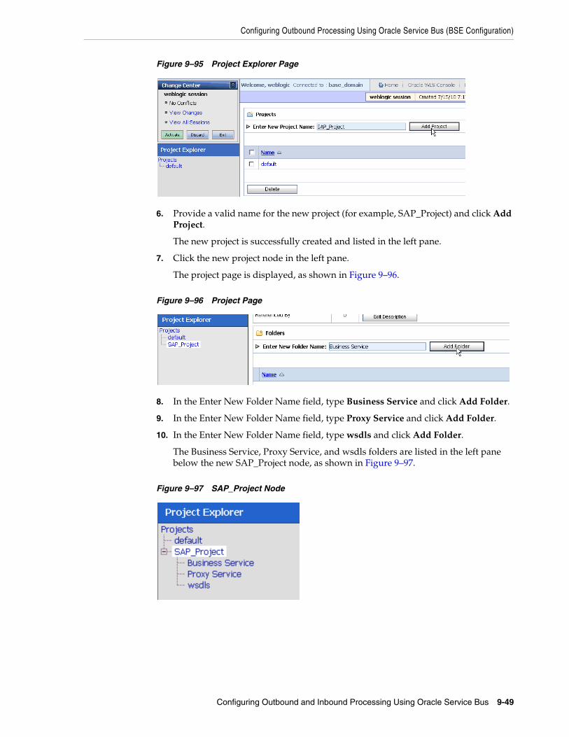
Configuring Outbound Processing Using Oracle Service Bus (BSE Configuration)
Configuring Outbound and Inbound Processing Using Oracle Service Bus 9-49
Figure 9–95 Project Explorer Page
6. Provide a valid name for the new project (for example, SAP_Project) and click Add Project.
The new project is successfully created and listed in the left pane.
7. Click the new project node in the left pane.
The project page is displayed, as shown in Figure 9–96.
Figure 9–96 Project Page
8. In the Enter New Folder Name field, type Business Service and click Add Folder.
9. In the Enter New Folder Name field, type Proxy Service and click Add Folder.
10. In the Enter New Folder Name field, type wsdls and click Add Folder.
The Business Service, Proxy Service, and wsdls folders are listed in the left pane below the new SAP_Project node, as shown in Figure 9–97.
Figure 9–97 SAP_Project Node

Configuring Outbound Processing Using Oracle Service Bus (BSE Configuration)
9-50 Oracle Fusion Middleware Application Adapter for SAP R/3 (SAP JCo 3.0) User's Guide for Oracle WebLogic Server
9.4.2 Setting the Class Path for Application Explorer to Integrate With Oracle Service Bus
Before starting and using Application Explorer to publish a WSDL directly to the Oracle Service Bus (OSB) Console (project/folder), OSB users must perform the following steps:
1. Open the command prompt window.
2. Navigate to the following directory:
<OSB_Home>\user_projects\domains\base_domain\bin
3. Execute setDomainEnv.cmd (Windows) or . ./setDomainEnv.sh (UNIX/Linux).
This command sets the class path for Application Explorer to access the Oracle WebLogic Server APIs to publish the WSDLs to the OSB Console.
4. Do not close the command prompt window.
5. Navigate to the following directory:
<OSB_Home>\3rdparty\ApplicationAdapters\tools\iwae\bin
6. Execute ae.bat (Windows) or iwae.sh (UNIX/Linux) to start Application Explorer.
You are now ready to publish WSDLs from Application Explorer to the OSB Console.
9.4.3 Publishing a WSDL From Application Explorer to Oracle Service BusThis section describes how to publish a WSDL from Application Explorer (BSE configuration) to Oracle Service Bus.
1. Start Application Explorer, connect to a BSE configuration, and connect to a SAP R/3 target.
Figure 9–98 Create Web Service Option
2. Expand the Business Object Repository node, Financial Accounting node, and the CompanyCode business object.

Configuring Outbound Processing Using Oracle Service Bus (BSE Configuration)
Configuring Outbound and Inbound Processing Using Oracle Service Bus 9-51
3. Right-click the GetDetail method and select Create Web Service from the menu, as shown in Figure 9–98.
The Create Web Service dialog is displayed, as shown in Figure 9–99.
Figure 9–99 Create Web Service Dialog
4. Enter a service name and click Next.
5. Click OK on the next dialog that is displayed.
Application Explorer switches the view to the Business Services node, and the new Web service appears in the left pane.
Figure 9–100 Export WSDL Option
6. Right-click the new Web service and select Export WSDL from the menu, as shown in Figure 9–100.
The Export WSDL dialog is displayed, as shown in Figure 9–101.

Configuring Outbound Processing Using Oracle Service Bus (BSE Configuration)
9-52 Oracle Fusion Middleware Application Adapter for SAP R/3 (SAP JCo 3.0) User's Guide for Oracle WebLogic Server
Figure 9–101 Export WSDL Dialog
7. In the Name field, a default file name for the WSDL file is provided. You can accept the default or provide your own.
8. In the Location field, enter the location where you want to publish the WSDL document.
The location is composed of an Oracle Service Bus project name and optionally, one or more folder names. The project name and any folder names must be separated by a forward slash character “/”.
9. In the Host field, enter the name of the machine where Oracle WebLogic Server is running.
10. In the Port field, enter the port for the domain you are using.
11. In the User field, enter your username to access Oracle Service Bus.
12. In the Password field, enter your password to access Oracle Service Bus.
13. Click OK.
The WSDL is published to the location specified in the Export WSDL dialog and is now available for use with a Business Service or Proxy Service in Oracle Service Bus.
9.4.4 Configuring a File Type Business ServiceThis section describes how to configure a File type Business Service using the Oracle Service Bus Console.
1. Select the Business Service folder you created in the left pane.

Configuring Outbound Processing Using Oracle Service Bus (BSE Configuration)
Configuring Outbound and Inbound Processing Using Oracle Service Bus 9-53
Figure 9–102 Business Service Option
2. In the right pane, select Business Service from the Create Resource menu, as shown in Figure 9–102.
The General Configuration page is displayed, as shown in Figure 9–103.
Figure 9–103 General Configuration Page
3. Provide a name for the Business Service and from the Service Type area select Messaging Service.
4. Click Next.
The Message Type Configuration page is displayed, as shown in Figure 9–104.

Configuring Outbound Processing Using Oracle Service Bus (BSE Configuration)
9-54 Oracle Fusion Middleware Application Adapter for SAP R/3 (SAP JCo 3.0) User's Guide for Oracle WebLogic Server
Figure 9–104 Message Type Configuration Page
5. Select XML as the Request Message Type and None as the Response Message Type.
6. Click Next.
The Transport Configuration page is displayed, as shown in Figure 9–105.
Figure 9–105 Transport Configuration Page
7. Select file from the Protocol list.
8. Enter the path to a destination folder on your file system in the Endpoint URI field and click Add.
9. Click Next.
The FILE Transport Configuration page is displayed, as shown in Figure 9–106.

Configuring Outbound Processing Using Oracle Service Bus (BSE Configuration)
Configuring Outbound and Inbound Processing Using Oracle Service Bus 9-55
Figure 9–106 FILE Transport Configuration Page
10. Enter the prefix and suffix for the output file to be received and click Next.
The Summary page is displayed, as shown in Figure 9–107.
Figure 9–107 Summary Page
11. Review all the information for your Business Service and click Save.
9.4.5 Configuring a WSDL Type Business ServiceThis section describes how to configure a WSDL type Business Service using the Oracle Service Bus Console.
1. Select the Business Service folder you created in the left pane.

Configuring Outbound Processing Using Oracle Service Bus (BSE Configuration)
9-56 Oracle Fusion Middleware Application Adapter for SAP R/3 (SAP JCo 3.0) User's Guide for Oracle WebLogic Server
Figure 9–108 Business Service Option
2. In the right pane, select Business Service from the Create Resource menu, as shown in Figure 9–108.
The General Configuration page is displayed, as shown in Figure 9–109.
Figure 9–109 General Configuration Page
3. Provide a name for the Business Service and from the Service Type area select WSDL Web Service.
4. Click Browse.
The Select a WSDL dialog is displayed, as shown in Figure 9–110.

Configuring Outbound Processing Using Oracle Service Bus (BSE Configuration)
Configuring Outbound and Inbound Processing Using Oracle Service Bus 9-57
Figure 9–110 Select a WSDL Dialog
5. Select a BSE WSDL that you published for Oracle Application Adapter for SAP R/3 using Application Explorer and click Submit.
The Select a WSDL Definition dialog is displayed, as shown in Figure 9–111.
Figure 9–111 Select a WSDL Definition Dialog

Configuring Outbound Processing Using Oracle Service Bus (BSE Configuration)
9-58 Oracle Fusion Middleware Application Adapter for SAP R/3 (SAP JCo 3.0) User's Guide for Oracle WebLogic Server
6. Select the required WSDL and then select the WSDL definition under the Ports section and click Submit.
You are returned to the General Configuration page where the WSDL you selected is now available.
7. Click Next.
The Transport Configuration page is displayed, as shown in Figure 9–112.
Figure 9–112 Transport Configuration Page
8. Leave the default values and click Next.
The HTTP Transport Configuration page is displayed, as shown in Figure 9–113.
Figure 9–113 HTTP Transport Configuration Page
9. Leave the default values and click Next.
The SOAP Binding Configuration page is displayed, as shown in Figure 9–114.

Configuring Outbound Processing Using Oracle Service Bus (BSE Configuration)
Configuring Outbound and Inbound Processing Using Oracle Service Bus 9-59
Figure 9–114 SOAP Binding Configuration Page
10. Click Next.
The Message Content Handling page is displayed, as shown in Figure 9–115.
Figure 9–115 Message Content Handling Page
11. Click Next.
The Summary page is displayed, as shown in Figure 9–116.

Configuring Outbound Processing Using Oracle Service Bus (BSE Configuration)
9-60 Oracle Fusion Middleware Application Adapter for SAP R/3 (SAP JCo 3.0) User's Guide for Oracle WebLogic Server
Figure 9–116 Summary Page
12. Review all the information for your Business Service and click Save.
9.4.6 Configuring a Proxy ServiceThis section describes how to configure a Proxy Service using the Oracle Service Bus Console.
1. Select the Proxy Service folder you created in the left pane.
Figure 9–117 Proxy Service Option
2. In the right pane, select Proxy Service from the Create Resource menu, as shown in Figure 9–117.
The General Configuration page is displayed, as shown in Figure 9–118.

Configuring Outbound Processing Using Oracle Service Bus (BSE Configuration)
Configuring Outbound and Inbound Processing Using Oracle Service Bus 9-61
Figure 9–118 General Configuration Page
3. Provide a name for the Proxy Service and from the Service Type area select Any XML Service.
4. Click Next.
The Transport Configuration page is displayed, as shown in Figure 9–119.
Figure 9–119 Transport Configuration Page
5. Select file from the Protocol list.
6. Enter the path to an input folder on your file system in the Endpoint URI field.
7. Click Next.
The FILE Transport Configuration page is displayed, as shown in Figure 9–120.

Configuring Outbound Processing Using Oracle Service Bus (BSE Configuration)
9-62 Oracle Fusion Middleware Application Adapter for SAP R/3 (SAP JCo 3.0) User's Guide for Oracle WebLogic Server
Figure 9–120 FILE Transport Configuration Page
8. Provide any folder locations on your file system for the Stage Directory and Error Directory fields.
9. Click Next.
The Message Content Handling page is displayed, as shown in Figure 9–121.
Figure 9–121 Message Content Handling Page
10. Click Next.
The Summary page is displayed, as shown in Figure 9–122.

Configuring Outbound Processing Using Oracle Service Bus (BSE Configuration)
Configuring Outbound and Inbound Processing Using Oracle Service Bus 9-63
Figure 9–122 Summary Page
11. Review all the information for your Proxy Service and click Save.
9.4.7 Configuring a PipelineThis section describes how to configure a Pipeline using the Oracle Service Bus Console.
1. Click the Edit Message Flow icon in the row of the Proxy Service you created, as shown in Figure 9–123.
Figure 9–123 Edit Message Flow Icon
The Edit Message Flow workspace area is displayed.
2. Click the Proxy Service icon and select Add Pipeline Pair from the menu, as shown in Figure 9–124.

Configuring Outbound Processing Using Oracle Service Bus (BSE Configuration)
9-64 Oracle Fusion Middleware Application Adapter for SAP R/3 (SAP JCo 3.0) User's Guide for Oracle WebLogic Server
Figure 9–124 Add Pipeline Pair Option
3. Click the Request Pipeline icon and select Add Stage from the menu, as shown in Figure 9–125.
Figure 9–125 Add Stage Option
The Stage1 icon is added below the Request Pipeline icon.

Configuring Outbound Processing Using Oracle Service Bus (BSE Configuration)
Configuring Outbound and Inbound Processing Using Oracle Service Bus 9-65
Figure 9–126 Edit Stage Option
4. Click the Stage1 icon and select Edit Stage from the menu, as shown in Figure 9–126.
The Edit Stage Configuration workspace area is displayed, as shown in Figure 9–127.
Figure 9–127 Edit Stage Configuration Workspace Area
5. Click Add an Action, select Reporting from the menu, and click Log.

Configuring Outbound Processing Using Oracle Service Bus (BSE Configuration)
9-66 Oracle Fusion Middleware Application Adapter for SAP R/3 (SAP JCo 3.0) User's Guide for Oracle WebLogic Server
Figure 9–128 Edit Stage Configuration Workspace Area
6. Click <Expression> to edit the expression, as shown in Figure 9–128.
The XQuery/XSLT Expression Editor is displayed, as shown in Figure 9–129.
Figure 9–129 XQuery/XSLT Expression Editor
7. In the XQuery Text area, type $inbound.
8. Click Validate and then Save.
You are returned to the Edit Stage Configuration workspace area, as shown in Figure 9–130.

Configuring Outbound Processing Using Oracle Service Bus (BSE Configuration)
Configuring Outbound and Inbound Processing Using Oracle Service Bus 9-67
Figure 9–130 Edit Stage Configuration Workspace Area
9. Type any annotation/comments in the text box (for example, **********input processing***********).
10. Select Error from the severity level list.
11. Add one more Log action as shown in Figure 9–131.
Figure 9–131 Log Action
A new Log configuration is added, as shown in Figure 9–132.

Configuring Outbound Processing Using Oracle Service Bus (BSE Configuration)
9-68 Oracle Fusion Middleware Application Adapter for SAP R/3 (SAP JCo 3.0) User's Guide for Oracle WebLogic Server
Figure 9–132 Log Configuration
12. Click <Expression> to edit the expression.
The XQuery/XSLT Expression Editor is displayed, as shown in Figure 9–133.
Figure 9–133 XQuery/XSLT Expression Editor
13. In the XQuery Text area, type $body.
14. Click Validate and then Save.
You are returned to the Edit Stage Configuration workspace area, as shown in Figure 9–134.

Configuring Outbound Processing Using Oracle Service Bus (BSE Configuration)
Configuring Outbound and Inbound Processing Using Oracle Service Bus 9-69
Figure 9–134 Edit Stage Configuration Workspave Area
15. Type any annotation/comments in the text box (for example, **********Request Body***********).
16. Select Error from the severity level list.
17. Click Validate and then Save.
Figure 9–135 Add Route Option
18. Click the PipelinePairNode1 icon and select Add Route from the menu, as shown in Figure 9–135.
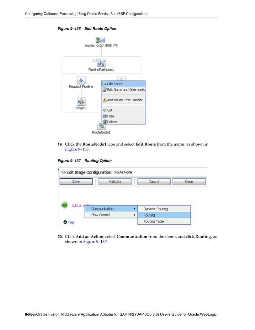
Configuring Outbound Processing Using Oracle Service Bus (BSE Configuration)
9-70 Oracle Fusion Middleware Application Adapter for SAP R/3 (SAP JCo 3.0) User's Guide for Oracle WebLogic Server
Figure 9–136 Edit Route Option
19. Click the RouteNode1 icon and select Edit Route from the menu, as shown in Figure 9–136.
Figure 9–137 Routing Option
20. Click Add an Action, select Communication from the menu, and click Routing, as shown in Figure 9–137.

Configuring Outbound Processing Using Oracle Service Bus (BSE Configuration)
Configuring Outbound and Inbound Processing Using Oracle Service Bus 9-71
Figure 9–138 Edit Stage Configuration Workspace Area
21. Click <Service>, as shown in Figure 9–138.
The Select Service dialog is displayed, as shown in Figure 9–139.
Figure 9–139 Select Service Dialog
22. Select a WSDL type Business Service and click Submit.
You are returned to the Edit Stage Configuration workspace area, as shown in Figure 9–140.

Configuring Outbound Processing Using Oracle Service Bus (BSE Configuration)
9-72 Oracle Fusion Middleware Application Adapter for SAP R/3 (SAP JCo 3.0) User's Guide for Oracle WebLogic Server
Figure 9–140 Edit Stage Configuration Workspace Area
23. Select GetDetail as the operational attribute from the list.
24. Click Validate and then Save.
Figure 9–141 Log Option
25. In the Response Actions area, click Add an Action, select Reporting from the menu, and click Log, as shown in Figure 9–141.
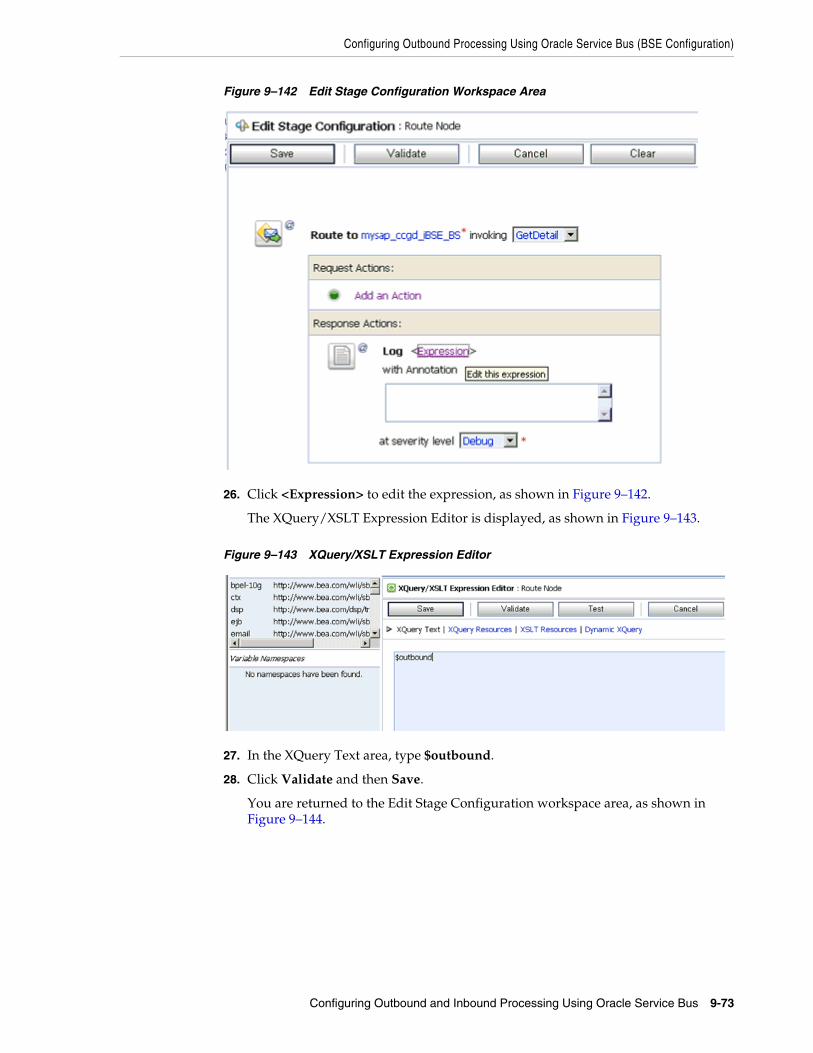
Configuring Outbound Processing Using Oracle Service Bus (BSE Configuration)
Configuring Outbound and Inbound Processing Using Oracle Service Bus 9-73
Figure 9–142 Edit Stage Configuration Workspace Area
26. Click <Expression> to edit the expression, as shown in Figure 9–142.
The XQuery/XSLT Expression Editor is displayed, as shown in Figure 9–143.
Figure 9–143 XQuery/XSLT Expression Editor
27. In the XQuery Text area, type $outbound.
28. Click Validate and then Save.
You are returned to the Edit Stage Configuration workspace area, as shown in Figure 9–144.

Configuring Outbound Processing Using Oracle Service Bus (BSE Configuration)
9-74 Oracle Fusion Middleware Application Adapter for SAP R/3 (SAP JCo 3.0) User's Guide for Oracle WebLogic Server
Figure 9–144 Edit Stage Configuration Workspace Area
29. Type any annotation/comments in the text box (for example, **********output processing***********).
30. Select Error from the severity level list.
31. Click Validate and then Save.
Figure 9–145 Add Stage Option
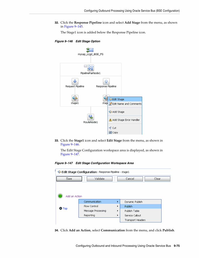
Configuring Outbound Processing Using Oracle Service Bus (BSE Configuration)
Configuring Outbound and Inbound Processing Using Oracle Service Bus 9-75
32. Click the Response Pipeline icon and select Add Stage from the menu, as shown in Figure 9–145.
The Stage1 icon is added below the Response Pipeline icon.
Figure 9–146 Edit Stage Option
33. Click the Stage1 icon and select Edit Stage from the menu, as shown in Figure 9–146.
The Edit Stage Configuration workspace area is displayed, as shown in Figure 9–147.
Figure 9–147 Edit Stage Configuration Workspace Area
34. Click Add an Action, select Communication from the menu, and click Publish.

Configuring Outbound Processing Using Oracle Service Bus (BSE Configuration)
9-76 Oracle Fusion Middleware Application Adapter for SAP R/3 (SAP JCo 3.0) User's Guide for Oracle WebLogic Server
Figure 9–148 Edit Stage Configuration Workspace Area
35. Click <Service>, as shown in Figure 9–148.
The Select Service dialog is displayed, as shown in Figure 9–149.
Figure 9–149 Select Service Dialog
36. Select a File type Business Service and click Submit.
You are returned to the Edit Stage Configuration workspace area, as shown in Figure 9–150.

Configuring Outbound Processing Using Oracle Service Bus (BSE Configuration)
Configuring Outbound and Inbound Processing Using Oracle Service Bus 9-77
Figure 9–150 Edit Stage Configuration Workspace Area
37. In the Request Actions area, click Add an Action, select Reporting from the menu, and click Log.
Figure 9–151 Edit Stage Configuration Workspace Area
38. Click <Expression> to edit the expression, as shown in Figure 9–151.
The XQuery/XSLT Expression Editor is displayed, as shown in Figure 9–152.

Configuring Outbound Processing Using Oracle Service Bus (BSE Configuration)
9-78 Oracle Fusion Middleware Application Adapter for SAP R/3 (SAP JCo 3.0) User's Guide for Oracle WebLogic Server
Figure 9–152 XQuery/XSLT Expression Editor
39. In the XQuery Text area, type $body.
40. Click Validate and then Save.
You are returned to the Edit Stage Configuration workspace area, as shown in Figure 9–153.
Figure 9–153 Edit Stage Configuration Workspace Area
41. Type any annotation/comments in the text box (for example, **********Response Body***********).
42. Select Error from the severity level list.
43. Click Validate and then Save.
The completed Pipeline is displayed, as shown in Figure 9–154.

Configuring Outbound Processing Using Oracle Service Bus (BSE Configuration)
Configuring Outbound and Inbound Processing Using Oracle Service Bus 9-79
Figure 9–154 Completed Pipeline
44. Click Save.
45. Click Activate in the Change Center area to activate your changes in the Oracle Service Bus session, as shown in Figure 9–155.
Figure 9–155 Change Center
46. Copy and paste an input XML file in the input folder you have configured, as shown in Figure 9–156.

Configuring Outbound Processing Using Oracle Service Bus (BSE Configuration)
9-80 Oracle Fusion Middleware Application Adapter for SAP R/3 (SAP JCo 3.0) User's Guide for Oracle WebLogic Server
Figure 9–156 Input XML File
An output XML file is received in the destination folder, as shown in Figure 9–157.
Figure 9–157 Received Output XML File

10
Troubleshooting and Error Messages 10-1
10 Troubleshooting and Error Messages
This chapter explains the limitations and workarounds when connecting to SAP R/3. It contains the following topics:
■ Section 10.1, "Troubleshooting"
■ Section 10.2, "BSE Error Messages"
The adapter-specific errors listed in this chapter can arise whether using the adapter with an Oracle Adapter J2CA or with an Oracle Adapter Business Services Engine (BSE) configuration.
10.1 TroubleshootingThis topic provides troubleshooting information for SAP R/3, separated into four categories:
■ Application Explorer
■ SAP R/3
■ Oracle Adapter J2CA
■ Oracle Adapter Business Services Engine (BSE)
Note: Log file information that can be relevant in troubleshooting can be found in the following locations:
■ The Oracle Adapter J2CA trace information can be found under the following directory:
<ADAPTER_HOME>\soa\thirdparty\ApplicationAdapters\config\config_name\log
■ BSE trace information can be found under the following directory:
<ADAPTER_HOME>\user_projects\domains\base_domain\servers\soa_server1\stage\ibse\ibse.war\ibselogs
■ The log file for Application Explorer can be found under the following directory:
<ADAPTER_HOME>\soa\thirdparty\ApplicationAdapters\tools\iwae\bin

Troubleshooting
10-2 Oracle Fusion Middleware Application Adapter for SAP R/3 (SAP JCo 3.0) User's Guide for Oracle WebLogic Server
Application ExplorerTo use Application Explorer on Windows for debugging or testing purposes:
1. Ensure that Oracle WebLogic Server is started, which is where Application Explorer is deployed.
2. Start Application Explorer by clicking the Windows Start menu, selecting All Programs, Oracle Application Adapters, and clicking Application Explorer, as shown in Figure 10–1.
Figure 10–1 Application Explorer Menu Selection
You can also start Application Explorer by executing the ae.bat file, which is located in the following directory:
<ADAPTER_HOME>\soa\thirdparty\ApplicationAdapters\tools\iwae\bin\ae.bat
It is a good practice to create a shortcut for the ae.bat file on your desktop.
If you are using a UNIX or Linux platform, then you can start Application Explorer by executing the iwae.sh file.
Error Solution
SAP R/3 does not appear in the Application Explorer Adapter node list.
Ensure that the sapjco3.jar and sapjco3.dll files are added to the lib directory.
Cannot connect to Oracle Application Adapter for SAP R/3 from Application Explorer.
Problem activating adapter
Ensure that:
■ SAP R/3 is running.
■ The Application Server name, System Number, and Client Number are correct.
■ The SAP R/3 user ID and password are correct.
Cannot connect to the SAP R/3 target through Application Explorer. The following error message appears:
Error getting target [SAP] - java.lang.Exception: Error Logon to SAP System
Ensure that you enter the correct connection parameters when connecting to the SAP R/3 target.

Troubleshooting
Troubleshooting and Error Messages 10-3
Cannot connect to your SAP R/3 system through Application Explorer. The following error message appears:
Problem activating adapter. (com.ibi.sapr3.SapAdapterException: com.sap.mw.jco.JCO$Exception: (102) RFC_ERROR_COMMUNICATION: Connect to SAP gateway failed Connect_PM GWHOST=isdsrv8, GWSERV=sapgw00, ASHOST=isdsrv8, SYSNR=00 LOCATION CPIC (TCP/IP) on local host ERROR partner not reached (host isdsrv8, service 3300) TIME Fri Aug 27 11:49:14 2004 RELEASE 620 COMPONENT NI (network interface) VERSION 36 RC -10 MODULE ninti.c LINE 979 DETAIL NiPConnect2 SYSTEM CALL SO_ERROR ERRNO 10061 ERRNO TEXT WSAECONNREFUSED: Connection refused COUNTER 1). Check logs for more information
Ensure that SAP R/3 is running and that you are using the correct parameter values to connect to your application server.
Cannot connect to your SAP R/3 system through Application Explorer even though SAP R/3 is running. The following error message appears:
Problem activating adapter. (com.ibi.sapr3.SapAdapterException: java.lang.ExceptionInInitializerError: JCO.classInitialize(): Could not load middleware layer 'com.sap.mw.jco.rfc.MiddlewareRFC' JCO.nativeInit(): Could not initialize dynamic link library sapjco3 [no sapjco3 in java.library.path]. java.library.path
Ensure that the sapjco3.dll file is added to the lib directory and to the Windows system32 folder.
The dll is loaded in another classloader (BSE and J2CA are installed on the same server). The following error message appears:
com.ibi.sapr3.SapAdapterException: java.lang.ExceptionInInitializerError: JCO.classInitialize(): Could not load middleware layer 'com.sap.mw.jco.rfc.MiddlewareRFC'
JCO.nativeInit(): Could not initialize dynamic link library sapjco3 [Native Library F:\iWay55.008.0628\lib\sapjco3.dll loaded in another classloader]. java.library.path
Add sapjco3.jar to the server classpath.
Error Solution

Troubleshooting
10-4 Oracle Fusion Middleware Application Adapter for SAP R/3 (SAP JCo 3.0) User's Guide for Oracle WebLogic Server
SAP R/3
Unable to start Application Explorer in a Solaris environment. The following exception is thrown in the console:
javax.resource.ResourceException: IWAFManagedConnectionFactory: License violation.at com.ibi.afjca.spi.IWAFManagedConnectionFactory.createConnectionFactory(IWAFManagedConnectionFactory.java:98)at com.iwaysoftware.iwae.common.JCATransport.getConnectionFactory(JCATransport.java:133) at com.iwaysoftware.iwae.common.JCATransport.initJCA(JCATransport.java:69)at com.iwaysoftware.iwae.common.JCATransport.<init>(JCATransport.java:62)at com.iwaysoftware.iwae.common.AdapterClient.<init>(AdapterClient.java:85)at com.ibi.bse.ConfigWorker.run(ConfigWorker.java:41)at java.lang.Thread.run(Thread.java:534)
Could not create the connection factory.
JAVACMD is not set on the user system. Before starting Application Explorer, export JAVACMD as follows:
JAVACMD=/<jdk_home>/bin/java, where <jdk_home> is the directory where JDK is installed on your system.
Logon failure error at run-time If the password for connecting to your SAP R/3 system is not specified when creating a target or with the Edit option in Application Explorer, then you are unable to connect to SAP R/3. The connection password is not saved in repository.xml. Update the password using the Edit option in Application Explorer, then restart the application server.
The following exception occurs when you start Application Explorer by activating ae.bat (not iaexplorer.bat):
java.lang.ClassNotFoundException: org.bouncycastle.jce.provider.BouncyCastleProvider
This is a benign exception. It does not affect adapter functionality. Download BouncyCastle files from:
ftp://ftp.bouncycastle.org/pub
Error Solution
When executing a request, the following error message appears:
AdapterException: java.lang.Exception: Function module CUSTOMER_GETDETAIL2 does NOT exist.
Check the syntax of your input XML document and make sure the name of the Remote Function module is correct, available in SAP R/3, and activated.
When executing a request, the following error message appears:
AdapterException: java.lang.Exception: Object type unknown for business object: CUST
Check the syntax of your input XML document and verify that the Business Object type exists in SAP R/3 and is correct and activated. Also verify that the name of your document is correct.
Error Solution

BSE Error Messages
Troubleshooting and Error Messages 10-5
Oracle Adapter J2CA
10.2 BSE Error MessagesThis topic discusses the different types of errors that can occur when processing Web services through BSE.
10.2.1 General Error Handling in BSEBSE serves as both a SOAP gateway into the adapter framework and as the engine for the adapters. In both design-time and run-time, various conditions can cause errors in BSE when Web services that use adapters run. These conditions and resulting errors are exposed the same way, regardless of the specific adapter; others are exposed differently, based on the adapter being used. This topic explains what you can expect if you encounter the more common error conditions on an adapter-specific basis.Usually the SOAP gateway (agent) inside BSE passes a SOAP request message to the adapter required for the Web service. If an error occurs, then how it is exposed
When executing a request, the following error message appears:
AdapterException: java.lang.Exception: Unable to retrieve BAPI name for: CUSTOMER.DETAIL2
Check the syntax of your input XML document and verify that the name of the BAPI is correct, available in SAP R/3, and activated.
When executing a request, the following error message appears:
java.lang.RuntimeException: com.sap.mw.jco.JCO$AbapException: (126) OBJECT_UNKNOWN: Basic type or extension does not exist.
Check the syntax of your input XML document and verify that the IDoc type or extension type is correct, available in SAP R/3, and activated.
When executing a request, the following error message appears:
AdapterException: java.lang.Exception: BapiError/BapiAbort: You are not authorized to display customers.
Verify that your user ID has the correct permissions configured in SAP R/3. Consult your SAP R/3 administrator for more information.
Note: Activation is an important SAP concept. If an object does not exist in an activated state, it may appear as present on the system, but is not available for use. This is especially important for IDOCs and SAP Business Objects. Consult your SAP documentation for further information.
Error Solution
In Application Explorer, the following error message appears when you attempt to connect to an Oracle Adapter J2CA configuration:
Could not initialize JCA
In the Details tab in the right pane, ensure that the directory specified in the Home field points to the correct directory, for example:
<ADAPTER_HOME>\soa\thirdparty\ApplicationAdapters\tools\iwae\bin\..\..\..\
Error Solution

BSE Error Messages
10-6 Oracle Fusion Middleware Application Adapter for SAP R/3 (SAP JCo 3.0) User's Guide for Oracle WebLogic Server
depends on the adapter and the API or interfaces that the adapter uses. A few scenarios cause the SOAP gateway to generate a SOAP fault. In general, anytime the SOAP agent inside BSE receives an invalid SOAP request, a SOAP fault element is generated in the SOAP response. The SOAP fault element contains fault string and fault code elements. The fault code contains a description of the SOAP agent error.
The following SOAP response document results when BSE receives an invalid SOAP request:
<SOAP-ENV:Envelope xmlns:SOAP-ENV="http://schemas.xmlsoap.org/soap/envelope/"> <SOAP-ENV:Body> <SOAP-ENV:Fault> <faultcode>SOAP-ENV:Client</faultcode> <faultstring>Parameter node is missing</faultstring> </SOAP-ENV:Fault> </SOAP-ENV:Body></SOAP-ENV:Envelope>
In this example, BSE did not receive an element in the SOAP request message that is mandatory for the WSDL for this Web service.
10.2.2 Adapter-Specific Error HandlingWhen an adapter raises an exception during run-time, the SOAP agent in BSE produces a SOAP fault element in the generated SOAP response. The SOAP fault element contains fault code and fault string elements. The fault string contains the native error description from the adapter target system. Since adapters use the target system interfaces and APIs, whether an exception is raised depends on how the target systems interface or API treats the error condition. If a SOAP request message is passed to an adapter by the SOAP agent in BSE and that request is invalid based on the WSDL for that service, then the adapter may raise an exception yielding a SOAP fault. While it is almost impossible to anticipate every error condition that an adapter may encounter, the following is a description of how adapters handle common error conditions and how they are then exposed to the Web services consumer application.
Oracle Application Adapter for SAP R/3 Invalid SOAP RequestIf Oracle Application Adapter for SAP R/3 receives a SOAP request message that does not conform to the WSDL for the Web services being carried out, then the following SOAP response is generated.
<?xml version="1.0" encoding="ISO-8859-1" ?> <SOAP-ENV:Envelope xmlns:SOAP-ENV="http://schemas.xmlsoap.org/soap/envelope/"><SOAP-ENV:Body><SOAP-ENV:Fault> <faultcode>SOAP-ENV:Server</faultcode> <faultstring>Error processing agent [XDSapIfrAgent] - XD[FAIL] SapIFRException: java.sql.SQLException: com.ibi.sapjco3.SapCallableStatement: execute() j java.util.NoSuchElementException</faultstring> </SOAP-ENV:Fault> </SOAP-ENV:Body></SOAP-ENV:Envelope>
Empty Result From SOAP RequestIf Oracle Application Adapter for SAP R/3 carries out an SAP R/3 object using input parameters passed in the SOAP request message that do not match records in SAP R/3, then the following SOAP response is generated.

BSE Error Messages
Troubleshooting and Error Messages 10-7
<?xml version="1.0" encoding="ISO-8859-1" ?> <SOAP-ENV:Envelope xmlns:SOAP-ENV="http://schemas.xmlsoap.org/soap/envelope/"><SOAP-ENV:Body> <SOAP-ENV:Fault> <faultcode>SOAP-ENV:Server</faultcode> <faultstring>Error processing agent [XDSapIfrAgent] - XD[FAIL] SapIFRException: java.sql.SQLException: com.ibi.sapjco3.SapCallableStatement: execute() java.sql.SQLException: JCO Error Key: NO_RECORD_FOUND Short Description:com.sap.mw.jco.JCO$AbapException: (126) NO_RECORD_FOUND: NO_RECORD_FOUND</faultstring> </SOAP-ENV:Fault> </SOAP-ENV:Body> </SOAP-ENV:Envelope>
Failure to Connect to SAP R/3If Oracle Application Adapter for SAP R/3 cannot connect to SAP R/3 when executing a Web service, then the following SOAP response is generated:
<?xml version="1.0" encoding="ISO-8859-1" ?> <SOAP-ENV:Envelope xmlns:SOAP-ENV="http://schemas.xmlsoap.org/soap/envelope/"><SOAP-ENV:Body> <SOAP-ENV:Fault> <faultcode>SOAP-ENV:Server</faultcode> <faultstring>Error processing agent [XDSapIfrAgent] - XD[RETRY] Connect to SAP gateway failed Connect_PM GWHOST=ESDSUN, GWSERV=sapgw00, ASHOST=ESDSUN,SYSNR=00 LOCATION CPIC (TCP/IP) on local host ERROR partner not reached (host ESDSUN, service 3300)TIME Mon Jun 30 16:01:02 2003 RELEASE 620 COMPONENT NI (network interface) VERSION 36 RC -10 MODULE ninti.c LINE 976 DETAIL NiPConnect2SYSTEM CALL SO_ERROR ERRNO 10061 ERRNO TEXT WSAECONNREFUSED: Connection refused COUNTER 1</faultstring> </SOAP-ENV:Fault> </SOAP-ENV:Body></SOAP-ENV:Envelope>
Invalid SOAP RequestIf Oracle Application Adapter for SAP R/3 receives a SOAP request message that does not conform to the WSDL for the Web services being carried out, then the following SOAP response is generated.
<?xml version="1.0" encoding="ISO-8859-1" ?><SOAP-ENV:Envelope xmlns:SOAP-ENV="http://schemas.xmlsoap.org/soap/envelope/"><SOAP-ENV:Body> <SOAP-ENV:Fault> <faultcode>SOAP-ENV:Server</faultcode> <faultstring>RPC server connection failed: Connection refused: connect</faultstring> </SOAP-ENV:Fault></SOAP-ENV:Body></SOAP-ENV:Envelope>
Empty Result From Oracle Application Adapter for SAP R/3 RequestIf Oracle Application Adapter for SAP R/3 carries out a SOAP request using input parameters passed that do not match records in the target system, then the following SOAP response is generated.

BSE Error Messages
10-8 Oracle Fusion Middleware Application Adapter for SAP R/3 (SAP JCo 3.0) User's Guide for Oracle WebLogic Server
<SOAP-ENV:Envelope xmlns:xsi="http://www.w3.org/1999/XMLSchema-instance" xmlns:SOAP-ENV="http://schemas.xmlsoap.org/soap/envelope/" xmlns:xsd="http://www.w3.org/1999/XMLSchema"> <SOAP-ENV:Body> <m:RunDBQueryResponse xmlns:m="urn:schemas-iwaysoftware-com:iwse" xmlns="urn:schemas-iwaysoftware-com:iwse" cid="2A3CB42703EB20203F91951B89F3C5AF"> <RunDBQueryResult run="1" /> </m:RunDBQueryResponse> </SOAP-ENV:Body></SOAP-ENV:Envelope>
Note: The condition for this adapter does not yield a SOAP fault.

11
Advanced User Tools 11-1
11 Advanced User Tools
This chapter contains the following topics:
■ Section 11.1, "Web Services Policy-Based Security"
■ Section 11.2, "Migrating Repositories"
11.1 Web Services Policy-Based SecurityApplication Explorer provides a security model called Web services policy-based security. The following topics describe how the feature works and how to configure it.
Web services provide a layer of abstraction between the back-end business logic and the user or application running the Web service, which enables easy application integration. However, the issue of controlling the use and implementation of critical and sensitive business logic that is run as a Web service is raised.
Application Explorer controls the use of Web services that use adapters, using a feature called policy-based security. This feature enables an administrator to apply "policies" to Business Services (Web services) to deny or permit their execution.
A policy is a set of privileges dealing with the execution of a Business Service (BS) that can be applied to an existing or new BS. When you set specific rights or privileges inside a policy, you do not have to re-create privileges for every BS that has security concerns in common with other Business Services. Instead, you reuse a policy on multiple Business Services.
The goal of the feature is to secure requests at both the transport and the SOAP request level transmitted on the wire. Some of the policies do not deal with security issues directly, but do affect the run-time behavior of the Web services to which they have been applied.
The Business Services administrator creates an "instance" of a policy type, names it, associates individual users or groups (a collection of users), and then applies that policy to one or more Business Services.
You can assign a policy to a Business Service, or to a method within a Business Service. If a policy is only applied to a method, then other methods in that Business Service are not governed by it. However, if a policy is applied to the Business Service, all methods are governed by it. At run-time, the user ID and password that are sent to BSE in the SOAP request message are verified against the list of users for all policies applied to that specific Business Service. The policy type that is supported is Resource Execution, which dictates who can or cannot perform the Business Service.
When a policy is not applied, the default value for a Business Service is to "grant all". For example, anybody can run the Business Service, until the Resource Execution policy is associated to the Business Service. At that time, only those granted execution

Web Services Policy-Based Security
11-2 Oracle Fusion Middleware Application Adapter for SAP R/3 (SAP JCo 3.0) User's Guide for Oracle WebLogic Server
permissions, or users not part of the group that has been denied execution permissions, have access to the Business Service.
11.1.1 Configuring Web Services Policy-Based SecurityThe following procedures describe how to configure Web services policy-based security.
Creating and Associating a User with a PolicyBefore you create instances of policies, you must have a minimum of one user or one group to associate to an instance. You can create users and groups using Application Explorer.
1. Open Application Explorer.
2. Right-click the configuration to which you want to connect, for example, SampleConfig. For information on creating a new configuration, see Chapter 4, "Configuring Oracle Application Adapter for SAP R/3".
3. Select Connect.
Nodes appear for Adapters and Business Services (also known as Web services), as shown in Figure 11–1.
Figure 11–1 Adapters and Business Services Nodes
Perform the following steps:
a. Expand the Business Services node.
b. Expand the Configuration node.
c. Expand the Security node.
d. Expand the Users and Groups node, as shown in Figure 11–2.
Figure 11–2 Users and Groups Node
4. Right-click Users and click New User.
The New User dialog is displayed, as shown in Figure 11–3.
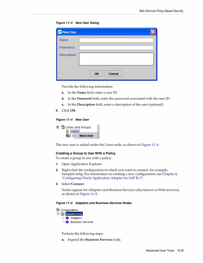
Web Services Policy-Based Security
Advanced User Tools 11-3
Figure 11–3 New User Dialog
Provide the following information:
a. In the Name field, enter a user ID.
b. In the Password field, enter the password associated with the user ID.
c. In the Description field, enter a description of the user (optional).
5. Click OK.
Figure 11–4 New User
The new user is added under the Users node, as shown in Figure 11–4.
Creating a Group to Use With a PolicyTo create a group to use with a policy:
1. Open Application Explorer.
2. Right-click the configuration to which you want to connect, for example, SampleConfig. For information on creating a new configuration, see Chapter 4, "Configuring Oracle Application Adapter for SAP R/3".
3. Select Connect.
Nodes appear for Adapters and Business Services (also known as Web services), as shown in Figure 11–5.
Figure 11–5 Adapters and Business Services Nodes
Perform the following steps:
a. Expand the Business Services node.

Web Services Policy-Based Security
11-4 Oracle Fusion Middleware Application Adapter for SAP R/3 (SAP JCo 3.0) User's Guide for Oracle WebLogic Server
b. Expand the Configuration node.
c. Expand the Security node.
d. Expand the Users and Groups node.
4. Right-click Groups and select New Group, as shown in Figure 11–6.
Figure 11–6 New Group
The New Group dialog is displayed, as shown in Figure 11–7.
Figure 11–7 New Group Dialog
Provide the following information:
a. In the Name field, enter a name for the group.
b. In the Description field, enter a description for the group (optional).
c. From the available list of users in the left pane, select one or more users and add them to the Selected list by clicking the double right-facing arrow.
5. When you have selected at least one user, click OK.
The new group is added under the Group node.
Creating an Execution PolicyAn execution policy governs who can run the Business Services to which the policy is applied.
To create an execution policy:
1. Open Application Explorer.
2. Right-click the configuration to which you want to connect, for example, SampleConfig. For information on creating a new configuration, see Chapter 4, "Configuring Oracle Application Adapter for SAP R/3".

Web Services Policy-Based Security
Advanced User Tools 11-5
3. Select Connect.
Nodes appear for Adapters and Business Services (also known as Web services), as shown in Figure 11–8.
Figure 11–8 Adapters and Business Services Nodes
Perform the following steps:
a. Expand the Business Services node.
b. Expand the Configuration node.
c. Expand the Security node.
d. Expand the Policies node.
4. Right-click Policies and select New Policy, as shown in Figure 11–9.
Figure 11–9 New Policy Option
The New policy dialog is displayed, as shown in Figure 11–10.
Figure 11–10 New Policy Dialog
Provide the following information:
a. In the Name field, enter a name for the policy.

Web Services Policy-Based Security
11-6 Oracle Fusion Middleware Application Adapter for SAP R/3 (SAP JCo 3.0) User's Guide for Oracle WebLogic Server
b. From the Type list, select Execution.
c. In the Description field, enter a description for the policy (optional).
d. From the available list of users in the left pane, select one or more users and add them to the Selected list by clicking the double right-facing arrow.
5. When you have selected at least one user selected, click OK.
6. Click Next.
The New Policy permissions dialog is displayed, as shown in Figure 11–11.
Figure 11–11 New Policy Permissions Dialog
■ To grant permission to a user or group to run a Business Service, select the user or group and move them into the Execution Granted list by selecting the double left-facing arrow.
■ To deny permission to a user or group to run a Business Service, select the user or group and move them into the Execution Denied list by selecting the double right-facing arrow.
7. Click OK.
A pane is displayed to summarize your configuration, as shown in Figure 11–12.
Note: This user ID is verified against the value in the user ID element of the SOAP header sent to BSE in a SOAP request.
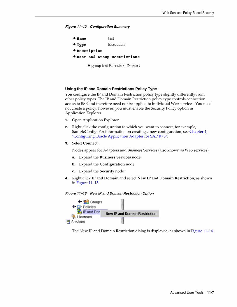
Web Services Policy-Based Security
Advanced User Tools 11-7
Figure 11–12 Configuration Summary
Using the IP and Domain Restrictions Policy TypeYou configure the IP and Domain Restriction policy type slightly differently from other policy types. The IP and Domain Restriction policy type controls connection access to BSE and therefore need not be applied to individual Web services. You need not create a policy; however, you must enable the Security Policy option in Application Explorer.
1. Open Application Explorer.
2. Right-click the configuration to which you want to connect, for example, SampleConfig. For information on creating a new configuration, see Chapter 4, "Configuring Oracle Application Adapter for SAP R/3".
3. Select Connect.
Nodes appear for Adapters and Business Services (also known as Web services).
a. Expand the Business Services node.
b. Expand the Configuration node.
c. Expand the Security node.
4. Right-click IP and Domain and select New IP and Domain Restriction, as shown in Figure 11–13.
Figure 11–13 New IP and Domain Restriction Option
The New IP and Domain Restriction dialog is displayed, as shown in Figure 11–14.
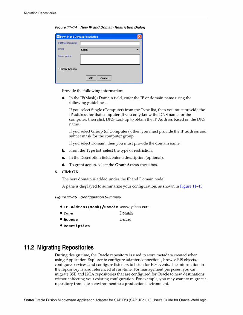
Migrating Repositories
11-8 Oracle Fusion Middleware Application Adapter for SAP R/3 (SAP JCo 3.0) User's Guide for Oracle WebLogic Server
Figure 11–14 New IP and Domain Restriction Dialog
Provide the following information:
a. In the IP(Mask)/Domain field, enter the IP or domain name using the following guidelines.
If you select Single (Computer) from the Type list, then you must provide the IP address for that computer. If you only know the DNS name for the computer, then click DNS Lookup to obtain the IP Address based on the DNS name.
If you select Group (of Computers), then you must provide the IP address and subnet mask for the computer group.
If you select Domain, then you must provide the domain name.
b. From the Type list, select the type of restriction.
c. In the Description field, enter a description (optional).
d. To grant access, select the Grant Access check box.
5. Click OK.
The new domain is added under the IP and Domain node.
A pane is displayed to summarize your configuration, as shown in Figure 11–15.
Figure 11–15 Configuration Summary
11.2 Migrating RepositoriesDuring design time, the Oracle repository is used to store metadata created when using Application Explorer to configure adapter connections, browse EIS objects, configure services, and configure listeners to listen for EIS events. The information in the repository is also referenced at run-time. For management purposes, you can migrate BSE and J2CA repositories that are configured for Oracle to new destinations without affecting your existing configuration. For example, you may want to migrate a repository from a test environment to a production environment.

Migrating Repositories
Advanced User Tools 11-9
Migrating a BSE RepositoryTo migrate a BSE repository:
1. Copy the BSE control service URL, for example:
http://localhost:8001/ibse/IBSEServlet/admin/iwcontrol.ibs
2. Open a third-party XML editor, for example, XMLSPY.
3. From the menu bar, click SOAP.
A list of options appears, as shown in Figure 11–16.
Figure 11–16 SOAP Menu
4. Select Create new SOAP request.
The WSDL file location dialog is displayed, as shown in Figure 11–17.
Figure 11–17 WSDL File Location Dialog
Perform the following steps:
a. In the Choose a file field, paste the BSE control service URL.
b. Append ?wsdl to the URL, for example:
http://localhost:8001/ibse/IBSEServlet/admin/iwcontrol.ibs?wsdl
5. Click OK.
The soap operation name dialog is displayed and the available control methods are listed, as shown in Figure 11–18.

Migrating Repositories
11-10 Oracle Fusion Middleware Application Adapter for SAP R/3 (SAP JCo 3.0) User's Guide for Oracle WebLogic Server
Figure 11–18 Soap Operation Name Dialog
6. Select the MIGRATEREPO(MIGRATEREPO parameters) control method and click OK.
The structure of the SOAP envelope is displayed, as shown in Figure 11–19.
Figure 11–19 SOAP Envelope
7. Locate the Text view icon in the toolbar, as shown in Figure 11–20.
Figure 11–20 Text View Icon
8. To display the structure of the SOAP envelope as text, click Text view.
Note: The MIGRATEREPO(MIGRATEREPO parameters) control method is available from the BSE administration console. This control method migrates all Web services to the new (empty) repository. You can choose to migrate select Web services only.

Migrating Repositories
Advanced User Tools 11-11
The <SOAP-ENV:Header> tag is not required and can be deleted from the SOAP envelope.
9. Locate the following section:
<m:MIGRATEREPO xmlns:m="urn:schemas-iwaysoftware-com:jul2003:ibse:config" version=""> <m:repositorysetting> <m:rname>oracle</m:rname> <m:rconn>String</m:rconn> <m:rdriver>String</m:rdriver> <m:ruser>String</m:ruser> <m:rpwd>String</m:rpwd> </m:repositorysetting> <m:servicename>String</m:servicename></m:MIGRATEREPO>
Perform the following steps:
a. For the <m:rconn> tag, replace the String placeholder with a repository URL where you want to migrate your existing BSE repository.
The Oracle repository URL has the following format:
jdbc:oracle:thin:@[host]:[port]:[sid]
b. For the <m:rdriver> tag, replace the String placeholder with the location of your Oracle driver.
c. For the <m:ruser> tag, replace the String placeholder with a valid user name to access the Oracle repository.
d. For the <m:rpwd> tag, replace the String placeholder with a valid password to access the Oracle repository.
10. Select and perform a migration option:
■ If you want to migrate a single Web service from the current BSE repository, then enter the Web service name in the <m:servicename> tag, for example:
<m:servicename>SAPService1</m:servicename>
■ If you want to migrate multiple Web services from the current BSE repository, then duplicate the <m:servicename> tag for each Web service, for example:
<m:servicename>SAPService1</m:servicename><m:servicename>SAPService2</m:servicename>
■ If you want to migrate all Web services from the current BSE repository, then remove the <m:servicename> tag.
11. From the menu bar, click SOAP and select Send request to server, as shown in Figure 11–21.
Figure 11–21 Send Request to Server Option

Migrating Repositories
11-12 Oracle Fusion Middleware Application Adapter for SAP R/3 (SAP JCo 3.0) User's Guide for Oracle WebLogic Server
Your BSE repository and any Web services you specified are now migrated to the new Oracle repository URL you specified.
Migrating a J2CA RepositoryTo migrate a J2CA repository:
1. Navigate to the location of your J2CA configuration directory where the repository schemas and other information is stored, for example:
<ADAPTER_HOME>\soa\thirdparty\ApplicationAdapters\config\JCA_CONFIG
Where JCA_CONFIG is the name of your J2CA configuration.
2. Locate and copy the repository.xml file.
3. Place this file in a new J2CA configuration directory to migrate the existing repository.
Your J2CA repository is migrated to the new J2CA configuration directory.

A
Understanding the SAP System Role in Remote Processing A-1
A Understanding the SAP System Role inRemote Processing
The Oracle Application Adapter for SAP R/3 exchanges messages with SAP using three different message type scenarios and two communication roles. Each role has configuration options that must be enabled on the SAP server and on the adapter to enable communications and send messages. This appendix explains the role types, message types, and their related terms. In an SAP Productive system environment, only the proper administrator for a particular configuration role has the authority to change or create the communications entries. This appendix provides a checklist for administrators for the required tasks and describes the entire process of configuring inbound and outbound message processing. This information can be used to configure non-productive systems or for reference purposes.
This appendix contains the following topics:
■ Section A.1, "Functionality of the Adapter"
■ Section A.2, "SAP Inbound Message Processing"
■ Section A.3, "SAP Outbound Message Processing"
A.1 Functionality of the AdapterImplementation of the Oracle Application Adapter for SAP R/3 uses the SAP Java Connector (JCo), a Java interface that communicates via Java Native Interface (JNI) to a native c communications layer. The RFC (Remote Function Call) API, implements the CPIC (Common Programming Interface - Communications) and TCP/IP protocols to communicate with a corresponding component on the SAP system. Each message is serialized to or from XML to RFC format, then marshaled into the current SAP message type for transmission to SAP. The SAP server unmarshalls the message into the current runtime object and executes the object. The response message is marshaled into RFC and returned to the adapter for unmarshalling and serialization to XML. This process is seamless and very rapid. Errors can arise from improper credentials, document encoding or actual application errors (for example, a wrong value for a given field).
A.1.1 RolesThe RFC protocol is a dynamic protocol depending on the mode of the request. When a request is inbound to a RFC connected node, the function of that node is a server to fill the request. When a request is outbound from a node, the function of that node is a client, waiting for a server to respond to the request. Outbound events, which need no response, are also processed by servers.

SAP Inbound Message Processing
A-2 Oracle Fusion Middleware Application Adapter for SAP R/3 (SAP JCo 3.0) User's Guide for Oracle WebLogic Server
A.1.2 ClientThe system instantiating a connection to another system is a client, and the client role processes request/response messages in a synchronous manner. A client system does not execute, but enables message processing. Messages begin and end on the client. The adapter functions as a client when it sends messages from Oracle to SAP.
Types of client connections include:
■ Application Server, which connects to a single SAP application server.
■ Message Server, which connects to an SAP logon load balancer message server for connection to a group of SAP application servers for distributed load processing.
Both connection types use a special type of connection called a Connection Pool, which is discussed later in this appendix.
Types of client message types include:
■ BAPI messages, which are object-style messages with parameters as XML attributes.
■ RFC messages, which are RFC-style messages with parameters as XML elements.
■ Intermediate Documents (IDocs), which use the ALE message system to send positional delimited flat text or XML element parameters.
A.1.3 ServerThe system receiving a connection request from another system is a server. A server executes message processing and returns results to a client. A server can reject a message request if it does not implement the processing for a given message with an exception for NOT_IMPLEMENTED. A server can process two types of messages:
■ Inbound messages, which contain the message request and the parameters for the request.
■ Synchronous messages, which take the inbound message request and either perform additional work, pass it to another system, or process it for additional processing before returning it to SAP.
The SAP application server waits for a synchronous message process to finish before continuing.
Types of server connections include:
■ Processing Mode (Request), a simple receipt of message type and parameters.
■ Response, which executes a synchronous process.
Types of server message types include:
■ RFC messages, which are RPC-style messages with parameters as elements.
■ Intermediate Documents (IDocs), which use the ALE message system to send positional delimited flat text or XML element parameters.
A.2 SAP Inbound Message ProcessingSending request / response (client) messages to an SAP system for Remote Function Call (RFC) or Business Application Interface (BAPI) objects requires a valid set of logon credentials. For more information on how to configure adapter targets, including the list of required parameters, see "Identifying SAP R/3 Logon Parameters"

SAP Inbound Message Processing
Understanding the SAP System Role in Remote Processing A-3
on page 2-3. For the valid values for the adapter target, see your SAP system administrator.
Obtain the following values before initial logon:
■ Valid SAP connection parameters.
■ SAP Communications user (a SAP GUI DIALOG user is not recommended for security reasons).
■ The correct SAP authorizations for the tasks the adapter is expected to perform.
SAP AuthorizationsThe proper SAP authorizations must be obtained before connecting to the server. It is a recommended SAP security practice to not allow RFC and DIAG access to the same user ID.
The basic authorization object used to secure RFC access is:
S_RFC: Secures the Function Group (located in authorization object class AAAB).
■ Authorization Object+S_RFC:
– Authorization Field:RFC_TYPE
– Authorization Value: "FUGR' is the only valid value.
– Authorization Field: RFC_NAME
– Authorization Value: The name of an activated function group. For example: ("ABCD") or '*'.
– Authorization Field: ACTVT
– Authorization Value: 16 (Execute) is the only valid value.
Individual function modules may have additional security inside their executable code. It is the requirement of the function developer or application creator to inform the users of the function or application of the authorization requirements to use the function or application. Consult the administrator to determine if there are additional authorizations required.
Individual tables may be secured from access by using the following authorization object:
S_TABU_DIS: Secures tables (located in authorization object class BC_A)
■ Authorization Object+S_TABU_DIS:
– Authorization Field: DICBERCLS: Or ("Authorization Group").
– Authorization Value: For example, Table: MARA is in group “MA”.
– Authorization Field: ACTVT
– Authorization Value: 03 (Display)
For a complete explanation on using this authorization object, see the SAP system documentation.
Once the correct credentials are specified for the adapter target and the correct authorizations are assembled on the SAP application system, the adapter is ready to be initialized.

SAP Inbound Message Processing
A-4 Oracle Fusion Middleware Application Adapter for SAP R/3 (SAP JCo 3.0) User's Guide for Oracle WebLogic Server
Request / Response (Client) MessagesBusiness Object Repository
Use Application Explorer to expand the appropriate application tree branch, such as Financial Accounting, and then navigate to and expand a Business Object, such as Company Code. Click the object to view the methods of that object. BAPIs have release and versioning. All BAPIs used at runtime must be in "release" status or a runtime exception is generated. Select a method to generate the XML schema. Create an XML instance document from the XML schema and populate it with data. Create an Oracle process with an appropriate input and output (file/html/etc) transmission method. Submit the document to the adapter for processing to receive a result.
Remote Function Call
Use Application Explorer to expand the appropriate application tree branch such as Financial Accounting and then navigate to and expand a Function Group, such as 0002 - Company Code. Each function exposes a different method of processing. All BAPIs are present as RFC objects because their implementation is via RFC. They can be called in this manner allowing for event processing, for example, when BAPI processing does not. Not all RFCs are present as BAPIs. Select a function and generate the XML schema. Create an XML instance document from the XML schema and populate it with data. Create an Oracle process with an appropriate input and output (file/html/etc) transmission method. Submit the document to the adapter for processing to receive a result.
ALE IDOC Message
SAP ERP ALE* Inbound Message processing, where IDocs are sent and stored in the SAP R/3 system, requires some configuration on the SAP server to be used. In this role, messages are sent to SAP as transactional data and stored on the SAP server. The document data is processed in a second step inside SAP, during a triggered workflow.
A.2.1 Configuring SAP R/3 Inbound ProcessingSending an IDoc to SAP ERP requires the following information about the message parties:
■ Sender of the message
■ Receiver of the message
■ Type of message that is being sent
The Sender and Receiver must be defined in the ALE system, and for each party, what kind of message each party is accepting and how it is being processed.
The Sending and Receiving system information are defined in units called Logical Systems, because the connection information does not involve physical connection information. A Logical System acts as a container for all the information about a particular Sender or Receiver.
Once a Logical System is defined, information about the different messages it sends and receives is stored in a Distribution Model. This model must be defined before any processing can occur, and it must be defined precisely to avoid Sender or Receiver errors. In the Distribution Model, the IDoc Message Application may also enable filters, which allow only specific parts of the IDoc to be sent, or distributed. There is a one-to-one correspondence between Logical System, Distribution Model, and Message Type. Complex filter rules can be configured by filter groups, filter objects, rules, and dependencies. For a complete explanation on configuring distribution models with filters, see the SAP system documentation.

SAP Inbound Message Processing
Understanding the SAP System Role in Remote Processing A-5
Processing an IDoc by the SAP system is defined in Partner Profiles. For each partner and message, it is possible to define process codes to (possibly) process messages differently.
Adapter Check ListFor sending messages to SAP, an ALE administrator must assign (after logon credentials):
1. Logical System name.
2. Message Types and IDoc Basic Types to be transmitted to the SAP application server.
Inside the SAP ERP system, the ALE Administrator must:
1. Create the Logical System.
2. Create the Distribution Model.
a. Assign the Sender for the model.
b. Assign the Receiver for the model.
c. Assign the Message Types.
3. Create a Partner Profile for the Logical System.
a. For each message type, assign a process code for SAP to process the message.
Example■ Logical System "ORACLIENT" is created (via SAP transaction SALE).
■ Distribution Model "ZORACLNT" is created (via SAP transaction BD64).
■ Message Type "MATMAS" is added for sending partner "ORACLIENT" and receiving partner "T90ALECNT" (ALE component of central host).
■ Partner Profile "ORACLIENT" is created (via SAP transaction WE20) and Inbound Message "MATMAS" is assigned with Process code "MATM".
You must perform the following steps to configure SAP R/3 for inbound IDoc processing:
1. Configure a Logical System.
2. Configure a Distribution Model.
3. Define an inbound Partner Profile.
A.2.2 Configuring a Logical SystemA Logical System is the container object for configuration information about the Sender or Receiver party of a message. It is a Logical System because no connection information is stored, only information about the message that the end point is able to process and the method used to process the message(s).
Note: The steps for configuring SAP ERP for inbound messages are described here as a reference. For more comprehensive information, see the SAP ERP documentation.

SAP Inbound Message Processing
A-6 Oracle Fusion Middleware Application Adapter for SAP R/3 (SAP JCo 3.0) User's Guide for Oracle WebLogic Server
SAP Transaction Shortcuts■ /n - Ends the current transaction and opens a new one immediately.
■ /o - Keeps the current transaction context and opens a new transaction in a new window.
Defining a Logical SystemA Logical System definition is created by creating an entry in the SAP Implementation Guide for Customizing (IMG).
ALE is the SAP ERP Application Link Enablement system, so use the /nSALE transaction to navigate to the IMG for ALE.
1. Navigate to the SALE transaction, as shown in Figure A–1.
Figure A–1 SALE Transaction
The Display IMG window displays the ALE configuration tree, as shown in Figure A–2.
Figure A–2 Display IMG Window
2. Perform the following steps:
a. Expand the Basic Settings node.
b. Expand Logical Systems.
c. Click Define Logical System.
d. Since SAP R/3 users may see a slightly different screen, expand the extra node, Sending and Receiving Systems.
The "Caution: The table is cross-client" message is displayed, as shown in Figure A–3.

SAP Inbound Message Processing
Understanding the SAP System Role in Remote Processing A-7
Figure A–3 Caution Message
This message appears to inform you that changes to customizing data in Logical Systems applies to all users of the SAP ERP server. This is in contrast to most application data, which is specifically bound to a logon client. Do not make any changes to Logical System entries. Only add the new information. Use an SAP logon ID with the correct privileges to do so.
3. Click the green check mark to continue.
The Change View "Logical Systems" window is displayed, as shown in Figure A–4.
Figure A–4 Change View "Logical Systems" Window
4. Click the New Entries button.
The New Entries: Overview of Added Entries window is displayed, as shown in Figure A–5.

SAP Inbound Message Processing
A-8 Oracle Fusion Middleware Application Adapter for SAP R/3 (SAP JCo 3.0) User's Guide for Oracle WebLogic Server
Figure A–5 New Entries: Overview of Added Entries Window
5. Enter the Logical System (for example, ORACLETDS) in the Log.System column and provide a description in the Name column.
6. Click the Save icon on the top menu bar, as shown in Figure A–6.
Figure A–6 Save Icon
The Prompt for Workbench request dialog is displayed.
7. Click the New Request icon to create a new request, as shown in Figure A–7.
Figure A–7 New Request Icon
8. Enter the description for your entry in the request system. The remaining fields are filled in automatically and do not need to be changed.
The Prompt for Workbench Request dialog is displayed again, with the new request number filled in with the last request number created in the Workbench; do not use it. Click the check mark to create a new request number, as shown in Figure A–8.
Note: The fields are highlighted in yellow to remind you that they are required fields.
Note: Depending on system usage, the last workbench request number appears in the dialog. Do not use it and proceed to the next step.

SAP Inbound Message Processing
Understanding the SAP System Role in Remote Processing A-9
Figure A–8 Prompt for Workbench Request Dialog
The Logical System Entries window refreshes with the new Logical System information. The new Logical System is highlighted in blue to indicate the successful completion of this step, as shown in Figure A–9.
Figure A–9 Logical System Entries Window
A.2.3 Configuring a Distribution Model for a Logical SystemA Distribution Model contains a Sender Logical System and a Receiver Logical System the type of Messages sent and received. If a given Sender or Receiver does not have a valid Distribution Model, then the message is not processed and routed to an error location. For advanced topics in Distribution Model, including SAP BAPI Objects and filtering, see the SAP documentation.
Defining a Distribution ModelTo define a distribution model:
1. Run the bd64 transaction, as shown in Figure A–10.
Figure A–10 Bd64 Transaction
The Display Distribution Model window is displayed in the default Display mode, which shows the current model view entries, as shown in Figure A–11.

SAP Inbound Message Processing
A-10 Oracle Fusion Middleware Application Adapter for SAP R/3 (SAP JCo 3.0) User's Guide for Oracle WebLogic Server
Figure A–11 Display Distribution Model
2. Expand the tree to view the entries for each model view.
To add items, the transaction must be switched into "change mode".
3. Click Distribution model and select Switch processing mode, as shown in Figure A–12.
Figure A–12 Switch Processing Mode Option
The screen refreshes and the model view window is switched to Change Distribution Model, as shown in Figure A–13.
Figure A–13 Change Distribution Model

SAP Inbound Message Processing
Understanding the SAP System Role in Remote Processing A-11
4. From the available menu buttons, select Create Model View.
The Create Model View dialog is displayed, as shown in Figure A–14.
Figure A–14 Create Model View Dialog
5. Enter a Model View name in the Short text field and a name in the Technical name field, which also serves as a description.
A good convention is to use names starting with the letter Z, since SAP does not overwrite these names in case of system updates. This is only the name of the Model View.
6. Click the green check mark icon to enter the information.
The screen refreshes and returns to the main Change Distribution Model window. The Distribution Model configured is now added to the list, as shown in Figure A–15.
Figure A–15 Change Distribution Model Window
The Model View is in temporary transaction storage (and the entry appears in lighter color) until you click the Save icon. If the system connection is lost or times out, then the entry is lost. As a best practice, save your changes after each dialog during the Distribution Model configuration process to avoid losing changes.
7. Place the cursor on the entry previously defined.
Figure A–16 New Distribution Model
The entry is now highlighted, as shown in Figure A–16.
8. In the middle menu bar, click the Add Message Type button.
The Add Message Type dialog is displayed.
9. Perform the following steps:
a. In the Sender field, enter the name of the sending Logical System for the Oracle system (for example, ORACLETDS). For more information, see "Configuring a Logical System" on page A-5.

SAP Inbound Message Processing
A-12 Oracle Fusion Middleware Application Adapter for SAP R/3 (SAP JCo 3.0) User's Guide for Oracle WebLogic Server
b. In the Receiver field, enter the name of the Client ALE Logical System for the SAP system (ALE receiver), or select from the drop-down (for example, T90CLNT090).
c. In the Message type field, enter the message type you want to use (for example, MATMAS).
You can click the drop-down icon to the right of each field to browse available values from a list.
d. Click the green check mark icon to enter the information.
The main Change Distribution Model window refreshes.
10. Click Save.
11. Navigate the ALE Hierarchy tree to the Distribution Model recently created. The Sender and Receiver are depicted in a graphical relationship with Sender, Receiver, and Message, as shown in Figure A–17.
Figure A–17 Sender, Receiver, and Message Components
For subsequent message types for the same systems, expand the Model View to the receiver name and place the cursor on the name. Then click the Add Message Type button. All the fields are populated automatically. You can then add the message type.
A.2.4 Defining a Partner ProfileA Partner Profile defines for each logical system, the messages processed, and how the message is processed. This allows for flexible configuration of processing details for partners. Each message type may have only one entry in a Partner Profile. To define a Partner Profile:
1. Run the we20 transaction, as shown in Figure A–18.
Figure A–18 We20 Transaction
The Partner profiles window is displayed, as shown in Figure A–19.

SAP Inbound Message Processing
Understanding the SAP System Role in Remote Processing A-13
Figure A–19 Partner Profiles Window
2. Select Partner Type LS and click the white icon on the middle menu bar. You can also select Create from the top menu.
The right side of the screen changes to a blank Partner Profile form, as shown in Figure A–20.
Figure A–20 Partner Profile Form
3. Enter the name of the Logical System (for example, ORACLETDS) in the partner number field and click the Save icon.
The screen changes with the new profile, as shown in Figure A–21.

SAP Inbound Message Processing
A-14 Oracle Fusion Middleware Application Adapter for SAP R/3 (SAP JCo 3.0) User's Guide for Oracle WebLogic Server
Figure A–21 New Partner Profile
4. Scroll down until the embedded text "Inbound parmtrs" entry is displayed.
5. Click the green plus sign icon.
The Partner profiles: Inbound parameters dialog is displayed, as shown in Figure A–22.
Figure A–22 Partner Profiles: Inbound Parameters Dialog

SAP Inbound Message Processing
Understanding the SAP System Role in Remote Processing A-15
6. Enter MATMAS as the Message Type.
7. Use the Process code drop down to find and select MATM for MATMAS.
8. Select Immediate or Background as the Process Mode.
9. Click the Save icon on the menu bar to save the Inbound Partner Profile entry for MATMAS.
10. Click the Back button on the menu bar to return to the previous window, as shown in Figure A–23.
Figure A–23 Back Button
MATMAS is displayed in the entry list, as shown in Figure A–24.
Figure A–24 MATMAS Message Type
This completes the inbound configuration for Logical System/Partner Profile: OracleTDS/MATMAS. To add additional inbound IDoc Message Type entries, repeat the steps beginning with "Configuring a Distribution Model for a Logical System" on page A-9. To add another Logical System and Message Type, repeat the steps from "Configuring a Logical System" on page A-5.
You can now begin sending IDocs after configuring the appropriate Oracle process.
From the SAP IDoc monitor console, you can monitor the IDoc transactions in SAP transaction WE02. The processing state and status of IDocs are available, as well as the Sender, Receiver, and the data, as shown in Figure A–25.
Note: Consult your SAP administrator for the proper settings.

SAP Outbound Message Processing
A-16 Oracle Fusion Middleware Application Adapter for SAP R/3 (SAP JCo 3.0) User's Guide for Oracle WebLogic Server
Figure A–25 SAP IDoc Monitor Console
A.3 SAP Outbound Message ProcessingThe Oracle Application Adapter for SAP R/3 can process two types of outbound from SAP application server messages, Remote Function Call messages or Transactional RFC messages with transaction ID. All communications processing via the SAP JCO is synchronous (request /response), but message processing can either be asynchronous (delivery only) or synchronous (an orchestrated process performs work and returns information to waiting SAP application server). RFC messages can be sent from SAP ABAP programs or the SAP workflow system or even the SAP function test transaction.
Outbound processing often is implemented as Events. On the SAP application server, there are many stages of defined events. Event processing is held together by linkages. Not all linkages are enabled by default on a Productive SAP server. For an Event to be active, and capable of sending messages, there must be an object capable of sending changes in the status of the object, a link to list of valid events, and event handlers. An event handler implements the processing of the message.
Active SAP Events are status changes on defined components with implemented event handlers. There are many types of events in the SAP application server, the most well known event handler is ALE Message Control, implemented by SAP around objects like the Material Master and Customer Master. Changes in these objects can generate outbound event IDocs.
Event creation is usually implemented by SAP, but many objects can be enabled for event handling, but this often requires advanced configuration or programming. Consult the SAP documentation for information on the type of SAP events and how they are configured.
For RFC outbound messages, only a SAP RFC Destination and Program ID are needed to receive the Remote Function Call.
For IDoc processing, a Logical System, Distribution Model, Partner Profile and Port must be created to receive message control events via tRFC.
SAP Outbound Terminology
■ JCO/RFC Client, which is the system making the RFC request, and optionally waiting for a response.
■ JCO/ RFC Server, which is the system receiving the RFC request, handling the request, and optionally receiving a response.
SAP Outbound Message Processing
Understanding the SAP System Role in Remote Processing A-17
A.3.1 SAP GatewayThe SAP Gateway is a process that runs on an SAP application server or a dedicated gateway server. The gateway process manages all connections to SAP. No server connections to SAP are accepted unless they are configured previously as registered programs in the SAP application and present the required program identifier.
A server connection presents itself to the Gateway and exposes a Program Identifier. If the Program Identifier is found in the list of registered Program IDs, then the Gateway server offers a connection to the server, which "accepts" a connection. This ProgramID is then linked with an RFC Destination within SAP, which enables SAP Function Modules and ALE documents (IDocs or BAPI IDocs) to be routed to the destination. The RFC Destination functions as a key to identify the SAP Program ID. The Program ID is also exposed by the application server making the connection to SAP and is the direct link to the IP address of the connecting server. Messages are routed to the application server via the RFC Destination. A good security practice is to separate Oracle Application Adapter for SAP R/3 users with access to the adapter instance implementing the Program id and the users with SAP transaction authority to change or view the Program ID inside SAP, all requests are routed through the RFC Destination.
A.3.2 Program IDs and Load BalancingIf the Gateway Server has a connection to a particular server instance and another server instance presents itself to the gateway, then the gateway offers the connection and then begins functioning in Load Balancing mode. Using a proprietary algorithm, the Gateway sends different messages to each server depending on demand and total processing time. This may cause unpredictable results when messages are validated by schema and application.
When configuring multiple events in the Oracle using a single SAP program ID, SAP load balances the event data. For example, if multiple remote function calls or BAPIs use the same program ID (for example, ORACLETDS) and multiple SAP listeners are configured with this progamID, then SAP sends one request to one listener and the next to another listener, and so on. There is a load-balancing algorithm present in the SAP Gateway Server. This mechanism is proprietary to SAP application development and might work by comparing total throughput of the connection, the number of times in wait state, and so on. One connection might receive nine messages and a second connection might receive one message. If five of the nine messages are rejected for schema validation and the one message on the other connection is rejected for schema validation, then you might suspect that you are missing SAP event handling messages.
Load balancing in server (inbound to adapter from SAP) situations is handled by connecting multiple instances of the adapter to the SAP system. The SAP system then load balances the connections. You cannot tune this performance.
Note: An RFC server program is registered with the SAP gateway and waits for incoming RFC call requests. An RFC server program registers itself under a Program ID at a SAP Gateway and not for a specific SAP system. In SAPGUI, the destination must be defined with transaction SM59, using connection type T and Register Mode. Moreover, this entry must contain information on the SAP gateway at which the RFC server program is registered.

SAP Outbound Message Processing
A-18 Oracle Fusion Middleware Application Adapter for SAP R/3 (SAP JCo 3.0) User's Guide for Oracle WebLogic Server
SAP RFC Outbound Outline1. Create a RFC Destination (via SM59).
a. Enter a Destination Name.
b. Enter a Registered Program ID.
c. In the MDMP & Unicode tab, ensure that the Unicode option is selected.
d. Start Oracle BPEL/Mediator.
e. Enter the same registered Program ID value from step b for the BPEL or Mediator channel.
f. Start the channel.
g. Test the connection using the Test button in SAP.
2. Simulate a SAP RFC message (via SE37).
ABAP Workbench authorization is required.
a. Enter the RFC Destination name from step 1a in the Destination field.
b. Enter a valid SAP RFC Function name in the Function field.
c. Enter data in the parameters for the function.
d. Click the Execute (clock) button.
Data arrives at the BPEL channel.
SAP IDoc EventsBefore IDocs can be received from SAP, a channel for the Oracle Application Adapter for SAP R/3 must be configured using Application Explorer. In addition, configuration on the SAP application server is also required.
1. Create a RFC Destination (via SM59) or use the same destination defined in the previous section (SAP RFC Outbound Outline).
a. Enter a Destination Name.
b. Enter a Registered Program ID.
c. In the MDMP & Unicode tab, ensure that the Unicode option is selected.
d. Start Oracle BPEL/Mediator.
e. Enter the same Registered Program ID value from step b for the BPEL or Mediator channel.
f. Start the channel.
g. Test the connection using the Test button in SAP.
2. Create or use a Logical System as described in "Configuring a Logical System" on page A-5.
3. Define or use a Distribution Model as described in "Configuring a Distribution Model for a Logical System" on page A-9.
4. Create an SAP Transactional RFC Port via transaction WE21.
5. Create an SAP Outbound Partner Profile via transaction WE20.
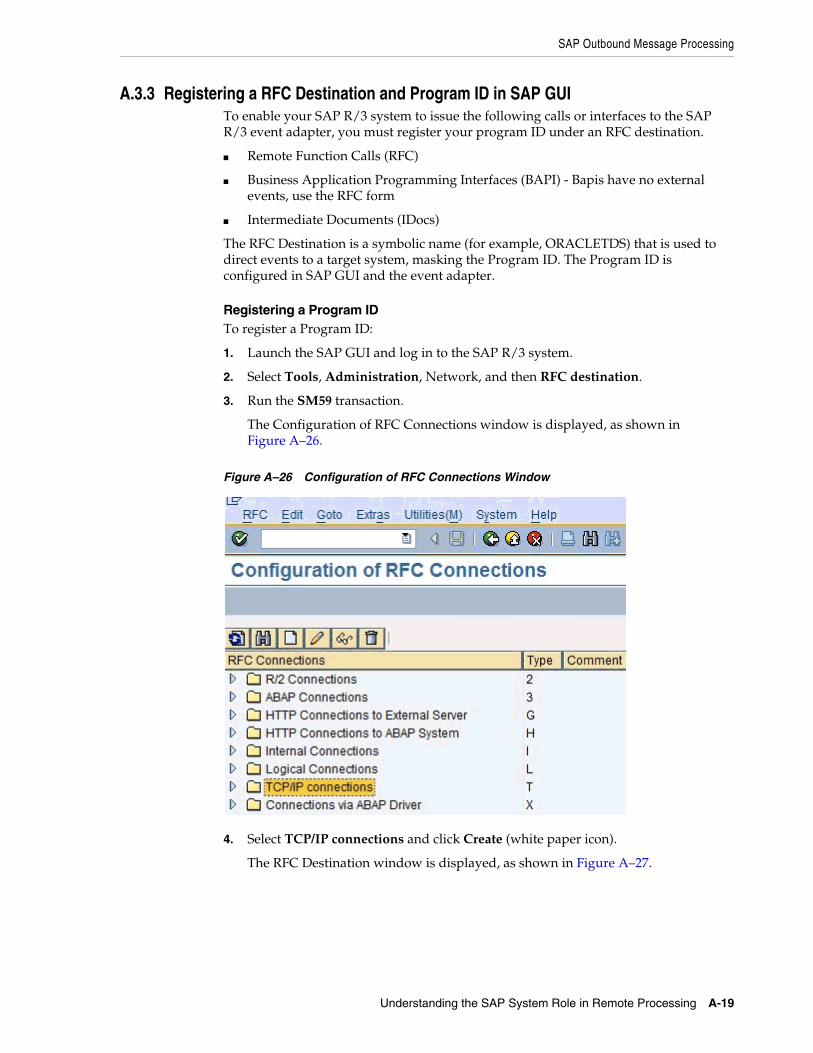
SAP Outbound Message Processing
Understanding the SAP System Role in Remote Processing A-19
A.3.3 Registering a RFC Destination and Program ID in SAP GUITo enable your SAP R/3 system to issue the following calls or interfaces to the SAP R/3 event adapter, you must register your program ID under an RFC destination.
■ Remote Function Calls (RFC)
■ Business Application Programming Interfaces (BAPI) - Bapis have no external events, use the RFC form
■ Intermediate Documents (IDocs)
The RFC Destination is a symbolic name (for example, ORACLETDS) that is used to direct events to a target system, masking the Program ID. The Program ID is configured in SAP GUI and the event adapter.
Registering a Program IDTo register a Program ID:
1. Launch the SAP GUI and log in to the SAP R/3 system.
2. Select Tools, Administration, Network, and then RFC destination.
3. Run the SM59 transaction.
The Configuration of RFC Connections window is displayed, as shown in Figure A–26.
Figure A–26 Configuration of RFC Connections Window
4. Select TCP/IP connections and click Create (white paper icon).
The RFC Destination window is displayed, as shown in Figure A–27.

SAP Outbound Message Processing
A-20 Oracle Fusion Middleware Application Adapter for SAP R/3 (SAP JCo 3.0) User's Guide for Oracle WebLogic Server
Figure A–27 RFC Destination Window
5. Provide the following information:
a. In the RFC destination field, enter a name, for example, ORACLETDS.
This field value is case-sensitive. Match the same case in the sending programs.
b. In the Connection type field, enter T for destination type TCP/IP.
c. In the Description field, enter a brief description.
6. Click the Save icon (Disk) from the tool bar or select Connection, Save from the top menu bar.
The window refreshes and the Technical Settings tab is highlighted in the second panel.
7. Immediately click the Registered Server Program button.
The screen refreshes again.
8. Enter the case sensitive Program Id, this must match the same name in the adapter channel
9. Click the Save icon (Disk) from the tool bar or select Connection, Save from the top menu bar.
10. Select the MDMP & Unicode tab and click the Unicode button.
11. Click the Save icon (Disk) from the tool bar or select Connection, Save from the top menu bar.
The RFC Destination and Program ID are now defined. Any Remote Function Call (RFC) can now be sent to the server via the Destination parameter of the Call Function API. The data for the function must be marshaled and sent to the adapter as this is a reverse invocation.
Testing the ConfigurationTo test the configuration:
1. Enter the Program ID in the BPEL process / channel for Oracle Application Adapter for SAP R/3 and start the channel.
2. Enter SAP GUI and navigate to SE37.
ABAP Workbench authorization is required.

SAP Outbound Message Processing
Understanding the SAP System Role in Remote Processing A-21
3. Enter a valid function name and click the Test Run (tool) icon, as shown in Figure A–28.
Figure A–28 Test Run (Tool) Icon
The Test Function Module: Initial Screen window is displayed, as shown in Figure A–29.
Figure A–29 Test Function Module: Initial Screen Window
4. Enter the name of the RFC Destination, any data, and then click the Execute (clock) icon.
Since this is reverse invocation, all data must be passed to the function for sending to the adapter. After a success, the execution time is displayed, as shown in Figure A–30. The first run is always the longest, subsequent runs are faster.
Figure A–30 RFC Destination
Synchronous RFC CallsSynchronous RFC calls are defined in the same way as asynchronous on the SAP side. On the adapter side, ensure "request_response" is selected as the mode for the call. Orchestrate a process that takes the SAP delivered data, processes it, and returns it to SAP in the function format. Any format errors immediately terminate the request. Example (in pseudo code):
Function: MY_COMPANY_GETLIST DESTINATION 'ORACLETDS’
tables mycompanies field1: name(20) field2: company(20)

SAP Outbound Message Processing
A-22 Oracle Fusion Middleware Application Adapter for SAP R/3 (SAP JCo 3.0) User's Guide for Oracle WebLogic Server
The synchronous Get List call passes the empty table mycompanies to BPEL server and SAP waits. BPEL orchestration includes an object that has the following SQL statement:
select name(20), company(20) into mycompanies where country eq us
The SQL statement is executed on an Oracle database and the result set is returned and passed into the mycompanies table by an assignment statement in the orchestration. Remember that the SAP application is waiting during the entire process, and that the SAP server may have a maximum online process time at which the process is automatically terminated by SAP.
The function returns to SAP via synchronous call and the table is returned with data to the calling process.
Time outs can occur if the execution time is longer than the connection pool execution time. Format exceptions can occur for type, length, or decimal places.
A.3.4 Application Link Embedding Configuration for the Event AdapterThe SAP R/3 event adapter receives IDocs (Intermediate Documents) from SAP R/3. To configure an SAP R/3 system to send IDocs to the SAP R/3 event adapter, use the ALE (Application Link Embedding) configuration to:
1. Register your program ID in SAP GUI.
2. Define a Port.
3. Create a Logical System.
4. Create a Partner Profile.
5. Create a Distribution Model for the Partner and Message Type.
6. Test the SAP R/3 event adapter.
A.3.5 Defining a PortA Port identifies where to send messages. The Port type used by Oracle Application Adapter for SAP R/3 is the Transactional RFC port. By defining an ALE port and linking it to the RFC Destination, this creates the message execution process pathway.
Defining a PortTo define a port:
1. In the ALE configuration, select Tools, Business Communications, IDocs Basis, IDoc, and then Port Definition.
You can also run the WE21 transaction.
The Ports in IDoc processing window is displayed, as shown in Figure A–31.
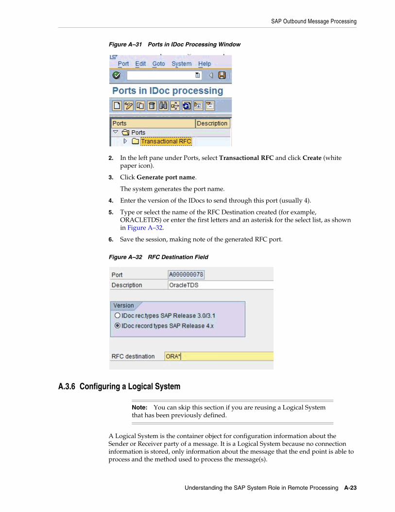
SAP Outbound Message Processing
Understanding the SAP System Role in Remote Processing A-23
Figure A–31 Ports in IDoc Processing Window
2. In the left pane under Ports, select Transactional RFC and click Create (white paper icon).
3. Click Generate port name.
The system generates the port name.
4. Enter the version of the IDocs to send through this port (usually 4).
5. Type or select the name of the RFC Destination created (for example, ORACLETDS) or enter the first letters and an asterisk for the select list, as shown in Figure A–32.
6. Save the session, making note of the generated RFC port.
Figure A–32 RFC Destination Field
A.3.6 Configuring a Logical System
A Logical System is the container object for configuration information about the Sender or Receiver party of a message. It is a Logical System because no connection information is stored, only information about the message that the end point is able to process and the method used to process the message(s).
Note: You can skip this section if you are reusing a Logical System that has been previously defined.

SAP Outbound Message Processing
A-24 Oracle Fusion Middleware Application Adapter for SAP R/3 (SAP JCo 3.0) User's Guide for Oracle WebLogic Server
SAP Transaction Shortcuts■ /n - Ends the current transaction and opens a new one immediately.
■ /o - Keeps the current transaction context and opens a new transaction in a new window.
Defining a Logical SystemA Logical System definition is created by creating an entry in the SAP Implementation Guide for Customizing (IMG).
ALE is the SAP ERP Application Link Enablement system, so use the /nSALE transaction to navigate to the IMG for ALE.
1. Navigate to the SALE transaction, as shown in Figure A–33.
Figure A–33 SALE Transaction
The Display IMG window displays the ALE configuration tree, as shown in Figure A–34.
Figure A–34 Display IMG Window
2. Perform the following steps:
a. Expand the Basic Settings node.
b. Expand Logical Systems.
c. Click Define Logical System.
d. Since SAP R/3 users may see a slightly different screen, expand the extra node, Sending and Receiving Systems.
The "Caution: The table is cross-client" message is displayed, as shown in Figure A–35.

SAP Outbound Message Processing
Understanding the SAP System Role in Remote Processing A-25
Figure A–35 Caution Message
This message appears to inform you that changes to customizing data in Logical Systems applies to all users of the SAP ERP server. This is in contrast to most application data, which is specifically bound to a logon client. Do not make any changes to Logical System entries. Only add the new information. Use an SAP logon ID with the correct privileges to do so.
3. Click the green check mark to continue.
The Change View "Logical Systems" window is displayed, as shown in Figure A–36.
Figure A–36 Change View "Logical Systems" Window
4. Click the New Entries button.
The New Entries: Overview of Added Entries window is displayed, as shown in Figure A–37.
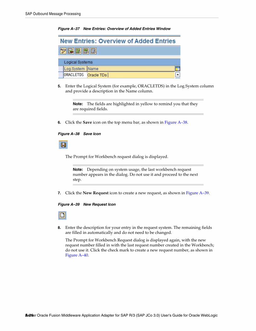
SAP Outbound Message Processing
A-26 Oracle Fusion Middleware Application Adapter for SAP R/3 (SAP JCo 3.0) User's Guide for Oracle WebLogic Server
Figure A–37 New Entries: Overview of Added Entries Window
5. Enter the Logical System (for example, ORACLETDS) in the Log.System column and provide a description in the Name column.
6. Click the Save icon on the top menu bar, as shown in Figure A–38.
Figure A–38 Save Icon
The Prompt for Workbench request dialog is displayed.
7. Click the New Request icon to create a new request, as shown in Figure A–39.
Figure A–39 New Request Icon
8. Enter the description for your entry in the request system. The remaining fields are filled in automatically and do not need to be changed.
The Prompt for Workbench Request dialog is displayed again, with the new request number filled in with the last request number created in the Workbench; do not use it. Click the check mark to create a new request number, as shown in Figure A–40.
Note: The fields are highlighted in yellow to remind you that they are required fields.
Note: Depending on system usage, the last workbench request number appears in the dialog. Do not use it and proceed to the next step.
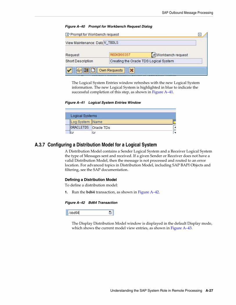
SAP Outbound Message Processing
Understanding the SAP System Role in Remote Processing A-27
Figure A–40 Prompt for Workbench Request Dialog
The Logical System Entries window refreshes with the new Logical System information. The new Logical System is highlighted in blue to indicate the successful completion of this step, as shown in Figure A–41.
Figure A–41 Logical System Entries Window
A.3.7 Configuring a Distribution Model for a Logical SystemA Distribution Model contains a Sender Logical System and a Receiver Logical System the type of Messages sent and received. If a given Sender or Receiver does not have a valid Distribution Model, then the message is not processed and routed to an error location. For advanced topics in Distribution Model, including SAP BAPI Objects and filtering, see the SAP documentation.
Defining a Distribution ModelTo define a distribution model:
1. Run the bd64 transaction, as shown in Figure A–42.
Figure A–42 Bd64 Transaction
The Display Distribution Model window is displayed in the default Display mode, which shows the current model view entries, as shown in Figure A–43.

SAP Outbound Message Processing
A-28 Oracle Fusion Middleware Application Adapter for SAP R/3 (SAP JCo 3.0) User's Guide for Oracle WebLogic Server
Figure A–43 Display Distribution Model Window
2. Expand the tree to view the entries for each model view.
To add items, the transaction must be switched into "change mode".
3. Click Distribution model and select Switch processing mode, as shown in Figure A–44.
Figure A–44 Switch Processing Mode Option
The screen refreshes and the model view window is switched to Change Distribution Model, as shown in Figure A–45.
Figure A–45 Change Distribution Model Window

SAP Outbound Message Processing
Understanding the SAP System Role in Remote Processing A-29
4. From the available menu buttons, select Create Model View.
The Create Model View dialog is displayed, as shown in Figure A–46.
Figure A–46 Create Model View Dialog
5. Enter a Model View name in the Short text field and a name in the Technical name field, which also serves as a description.
A good convention is to use names starting with the letter Z, since SAP does not overwrite these names in case of system updates. This is only the name of the Model View.
6. Click the green check mark icon to enter the information.
The screen refreshes and returns to the main Change Distribution Model window. The Distribution Model configured is now added to the list, as shown in Figure A–47.
Figure A–47 Change Distribution Model Window
The Model View is in temporary transaction storage (and the entry appears in lighter color) until you click the Save icon. If the system connection is lost or times out, then the entry is lost. As a best practice, save your changes after each dialog during the Distribution Model configuration process to avoid losing changes.
7. Place the cursor on the entry previously defined.
Figure A–48 New Distribution Model
The entry is now highlighted, as shown in Figure A–48.
8. In the middle menu bar, click the Add Message Type button.
The Add Message Type dialog is displayed.
9. Enter the ALE Central Instance Sender.
Consult your SAP administrator for this information.
10. Enter the Receiver (for example, ORACLETDS) in the Receiver field.
11. Enter a valid Message Type.
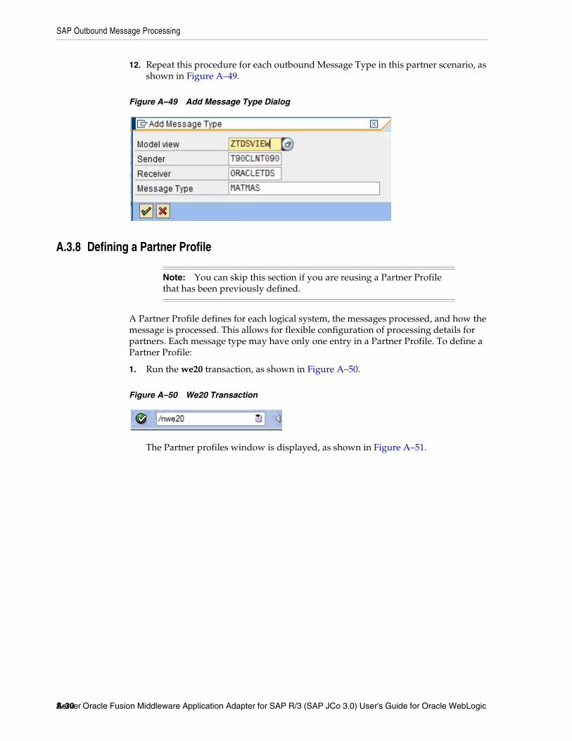
SAP Outbound Message Processing
A-30 Oracle Fusion Middleware Application Adapter for SAP R/3 (SAP JCo 3.0) User's Guide for Oracle WebLogic Server
12. Repeat this procedure for each outbound Message Type in this partner scenario, as shown in Figure A–49.
Figure A–49 Add Message Type Dialog
A.3.8 Defining a Partner Profile
A Partner Profile defines for each logical system, the messages processed, and how the message is processed. This allows for flexible configuration of processing details for partners. Each message type may have only one entry in a Partner Profile. To define a Partner Profile:
1. Run the we20 transaction, as shown in Figure A–50.
Figure A–50 We20 Transaction
The Partner profiles window is displayed, as shown in Figure A–51.
Note: You can skip this section if you are reusing a Partner Profile that has been previously defined.

SAP Outbound Message Processing
Understanding the SAP System Role in Remote Processing A-31
Figure A–51 Partner Profiles Window
2. Select Partner Type LS and click the white icon on the middle menu bar. You can also select Create from the top menu.
The right side of the screen changes to a blank Partner Profile form, as shown in Figure A–52.
Figure A–52 Partner Profile Form
3. Enter the name of the Logical System (for example, ORACLETDS) in the partner number field and click the Save icon.
The screen changes with the new profile, as shown in Figure A–53.

SAP Outbound Message Processing
A-32 Oracle Fusion Middleware Application Adapter for SAP R/3 (SAP JCo 3.0) User's Guide for Oracle WebLogic Server
Figure A–53 Partner Profiles: Outbound Parameters
4. Enter the Message Type in the Message Type field.
5. Enter the Port Number in the Receiver Port field
6. Select the Transfer IDoc immed. button or select Collect IDoc, specify a batch size, and use bd87 to release IDocs for processing.
7. Enter the Basic Type (MATMAS05 for MATMAS, etc.).
8. Click the Save icon.
A.3.9 Testing the SAP R/3 ALE ConfigurationIn the SAP Server, the BD12 transaction enables the sending of Master Data IDocs to any logical system, for example, to an event adapter.
Testing the SAP R/3 ALE ConfigurationTo test the SAP R/3 Application Link Embedding (ALE) configuration:
1. In the Send Customers window, enter the IDoc message type (for example, DEBMAS) in the Output type field, as shown in Figure A–54.

SAP Outbound Message Processing
Understanding the SAP System Role in Remote Processing A-33
Figure A–54 Send Customers Window
2. In the Logical system field, enter the logical system, for example, ORACLETDS
3. Click Run.
The SAP R/3 event adapter receives the IDoc in XML format. No response is expected from the event adapter.
A confirmation message is displayed, as shown in Figure A–55.
Figure A–55 Confirmation Message
The same number of communication IDocs should also be generated. The IDocs should appear at the adapter server shortly. If no IDocs appear, then check the following:
1. The Collect IDocs option is selected in the Partner Profile (go to bd87 to release).
2. No other server exposing the same Program ID.
SAP IDoc EventsBefore IDocs can be received from SAP, a channel for the Oracle Application Adapter for SAP R/3 must be configured using Application Explorer. In addition, configuration on the SAP application server is also required.
1. Create a RFC Destination (via SM59) or use the same destination defined in the previous section (SAP RFC Outbound Outline).
a. Enter a Destination Name.
b. Enter a Registered Program ID.

SAP Outbound Message Processing
A-34 Oracle Fusion Middleware Application Adapter for SAP R/3 (SAP JCo 3.0) User's Guide for Oracle WebLogic Server
c. In the MDMP & Unicode tab, ensure that the Unicode option is selected.
d. Start Oracle BPEL/Mediator.
e. Enter the same Registered Program ID value from step b for the BPEL or Mediator channel.
f. Start the channel.
g. Test the connection using the Test button in SAP.
2. Create or use a Logical System as described in "Configuring a Logical System" on page A-5.
3. Define or use a Distribution Model as described in "Configuring a Distribution Model for a Logical System" on page A-9.
4. Create an SAP Transactional RFC Port via transaction WE21.
5. Create an SAP Outbound Partner Profile via transaction WE20.

Glossary-1
Glossary
adapter
Provides universal connectivity by enabling an electronic interface to be accommodated (without loss of function) to another electronic interface.
agent
Supports service protocols in listeners and documents.
business service
Also known as a Web service. A Web service is a self-contained, modularized function that can be published and accessed across a network using open standards. It is the implementation of an interface by a component and is an executable entity.
channel
Represents configured connections to particular instances of back-end systems. A channel binds one or more event ports to a particular listener managed by an adapter.
listener
A component that accepts requests from client applications.
port
Associates a particular business object exposed by the adapter with a particular disposition. A disposition is a URL that defines the protocol and location of the event data. The port defines the end point of the event consumption.

port
Glossary-2

Index-1
Index
Aaccess rights, 11-1adapter configuration
updating, 5-2adapter exceptions, 10-4 to 10-6adapter types
resource, 1-1, 5-1 to 5-2adapters
configuring, 4-1 to 4-24, 5-2deploying, 1-4, 5-1 to 5-2, 6-1, 8-1integrating with BPEL Process Manager, 6-1, 8-1troubleshooting, 10-1 to 10-7
Adapters node, 6-45Add Channel dialog box, 4-19Add Target dialog box, 4-6Advanced tab, 4-9, 4-22, 6-43application adapters
configuring, 4-1 to 4-24, 5-2deploying, 5-1 to 5-2, 6-1, 8-1integrating with BPEL Process Manager, 6-1, 8-1troubleshooting, 10-1 to 10-7
Application Explorer, 1-2, 6-7, 6-41application systems and, 4-5channels and, 4-19debugging and, 10-3J2CA configuration and, 5-2OracleAS Adapter J2CA and, 10-5schemas and, 4-14security and, 11-1, 11-7testing and, 10-3troubleshooting, 10-2 to 10-3WSDL files and, 6-41
Application Server dialog box, 4-6Application Server parameter, 4-8application systems
Application Explorer and, 4-5supported, 4-5
Available list, 11-4 to 11-5
BBAPI (Business Application Programming
Interfaces), 10-4BAPI Exception parameter, 4-9, 4-22, 6-43BAPI requests, 1-4
BPEL Designer, 6-1, 8-1BPEL Process Manager
integrating with adapters, 6-1, 8-1OracleAS Adapter for MySAP ERP and, 6-1, 8-1
BSE (OracleAS Adapter Business Services Engine), 1-1, 1-4
connection access to, 11-7troubleshooting, 10-5
BSE control service URL, 11-9BSE repositories
migrating, 11-8BSE URL field, 4-3Business Application Programming Interfaces
(BAPI), 10-4business events, 1-1business functions, 4-5, 4-14 to 4-17
creating schemas for, 4-14business processes, 1-3business services
creating, 4-16 to 4-17deploying, 11-1testing, 4-17
Business Services node, 11-2 to 11-5, 11-7
CCCI calls, 5-1channels, 4-19
Application Explorer and, 4-19creating, 4-19, 6-41 to 6-44deleting, 4-24editing, 4-24starting, 4-24, 6-44stopping, 4-24, 6-44testing and debugging and, 6-44
Channels node, 4-20, 6-41channels. See also listenersClient parameter, 4-7, 4-21, 6-43Code page parameter, 4-7, 4-21, 6-43Commit with wait parameter, 4-9, 4-22, 6-43Configuration node under Business
Services, 11-2 to 11-5, 11-7configuration parameters, 5-4
IWayConfig, 5-4IWayHome, 5-4IWayRepoPassword, 5-4

Index-2
IWayRepoURL, 5-4IWayRepoUser, 5-4Loglevel, 5-4
configurationsconnecting to, 4-5defining, 4-2 to 4-4overwriting, 5-4
Configurations node, 4-2 to 4-3configuring adapters, 4-1 to 4-24, 5-2connecting to MySAP ERP, 4-5 to 4-12, 6-8, 6-45,
10-2, 10-7connecting to OracleAS Adapter J2CA, 10-5Connection dialog box, 4-12, 6-45connection parameters, 4-7 to 4-12, 4-21 to 4-22, 10-2
Advanced, 4-9, 4-22, 6-43Application Server, 4-8BAPI Exception Handling, 4-9Client, 4-7, 4-21, 6-43Code page, 4-7Commit with wait, 4-9Connection pool name, 4-9Connection pool size, 4-9EDI Version, 4-8Language, 4-7Logon ticket (SSO2), 4-10Logon ticket (X509), 4-10MySAP ERP Trace, 4-7Password, 4-7, 4-21, 6-43Security, 4-10SNC level, 4-10SNC library path, 4-11, 4-22, 6-44SNC mode, 4-10SNC name, 4-10SNC partner, 4-10System, 4-7, 4-21, 6-43System Number, 4-8User, 4-7, 4-21, 6-43
Connection pool name parameter, 4-9, 4-22, 6-43Connection pool size parameter, 4-9, 4-22, 6-43connections
closing, 4-12deleting, 4-12establishing, 4-5 to 4-12, 6-45
Connectordeploying to Oracle Application Server, 5-1
connector factories, 5-2connector factory objects, 5-2
multiple, 5-4control methods, 11-10Create Outbound JCA Service
(Request/Response), 6-9Create Web Service dialog box, 4-17creating channels, 6-41 to 6-44creating events, 6-45 to 6-48creating repository projects, 4-2 to 4-4customer master data, 6-65
Ddatabase connections
opening, 5-4databases
connecting to, 5-4Oracle, 5-4
DEBMAS05locating, 6-45
deploying adapters, 5-1 to 5-2, 6-1, 8-1Description field, 4-6, 4-17, 11-3 to 11-5, 11-8design time, 6-41, 11-8
configuring, 6-7, 6-41disconnecting from MySAP ERP, 4-12DNS Lookup option, 11-8DNS name, 11-8Domain Name System (DNS), 11-8domain names, 11-8Domain option, 11-8
EEclipse. See JDeveloperEDI Version parameter, 4-8editing channels, 4-24editing targets, 4-13EJB (Enterprise Java Beans), 5-1Enterprise Connector for J2EE Connector Architecture
(J2CA), 1-4Enterprise Java Beans (EJB), 5-1error messages, 10-2 to 10-7
target systems and, 10-6event adapters
configuring, 4-19event handling, A-1event integration
verifying, 6-65event messages, 6-41event ports
creating, 6-45 to 6-48events, 1-1, 4-19, A-1
configuring, 4-19creating, 6-45 to 6-48triggering, 6-65
Execution Denied list, 11-6Execution Granted list, 11-6Existing Service Names list, 4-17Export WSDL dialog box, 6-46
Ffault code elements, 10-6fault string elements, 10-6
GGrant Access check box, 11-8Group (of Computers) option, 11-8Group node, 11-4groups
creating, 11-3

Index-3
HHostname parameter, 4-3
IIDoc (Intermediate Documents), 10-4IDoc requests, 1-4in, 4-22inbound J2CA services, 6-41input XML documents, 10-4installation directories, 5-4instances of policy types, 11-1Intermediate Documents (IDoc), 10-4IP (Mask)/Domain field, 11-8IP addresses, 11-8IP and Domain Restriction policy type, 11-7IWayConfig parameter, 5-4IWayHome parameter, 5-4IWayRepoPassword parameter, 5-4IWayRepoURL parameter, 5-4IWayRepoUser parameter, 5-4
JJ2CA (Enterprise Connector for J2EE Connector
Architecture), 1-4OracleAS Adapter and, 5-1
J2CA configurationApplication Explorer and, 5-2
J2CA repositoriesmigrating, 11-12
J2CA resource adapters, 1-1, 5-1J2CA services, 6-41Java program clients, 5-1JDeveloper, 6-1, 8-1
LLanguage parameter, 4-7, 4-21, 6-43License and Method dialog box, 4-17License field, 4-17licenses, 4-17list of nodes, 10-2listeners, 1-4, 4-5listeners. See also channelslocating DEBMAS05, 6-45log files, 10-1log levels
overwriting, 5-4logical systems, 6-65Loglevel parameter, 5-4Logon ticket (SS02) parameter, 4-10Logon ticket (X509) parameter, 4-10
Mmanaged connector factories, 5-2managed connector factory objects, 5-2
multiple, 5-4ManagedConnectionFactory parameter, 5-4
Mediator Inbound Process, 7-27Mediator Outbound Process, 7-2Message Server dialog box, 4-19message types
event, 6-41messages, 1-1metadata
storing, 11-8Method Name field, 4-17methods, 11-1migrating repositories, 11-8migrating Web services, 11-11MySAP Easy Access window, 6-65MySAP ERP
connecting to, 1-3, 4-5 to 4-12, 6-8, 6-45, 10-2, 10-7disconnecting from, 4-12integrating, 1-3
MySAP ERP business functions, 4-5, 4-14 to 4-17creating schemas for, 4-14
MySAP ERP business processes, 1-3MySAP ERP platforms, 1-3MySAP ERP Trace parameter, 4-7, 4-21, 6-43MySAP node, 6-45MySAP program ID (identifiers), 6-65MySAP Workbench, 6-65
NName field, 4-6, 11-3 to 11-5New Configuration dialog box, 4-3 to 4-4New Group dialog box, 11-4New Policy permissions dialog box, 11-6New User dialog box, 11-2Node list, 10-2nodes
Adapters, 6-45Business Services, 11-2 to 11-5Channels, 4-20, 6-41Configuration under Business
Services, 11-2 to 11-5, 11-7Configurations, 4-2 to 4-3connected, 4-12, 6-45disconnected, 4-13Group, 11-4MySAP, 6-45Policies, 11-5Ports, 6-41Security, 11-5, 11-7Users, 11-3Users and Groups, 11-2 to 11-3
OObject type, 10-4OC4J-ra.xml file, 5-2 to 5-4Oracle Application Server
deployment of Connector to, 5-1Oracle databases, 5-4Oracle JDeveloper, 6-1, 8-1Oracle JDeveloper BPEL Designer. See BPEL Designer,

Index-4
JDeveloper, or Oracle JDeveloperOracle repositories
migrating, 11-8Oracle's Unified Method (OUM), viiiOracleAS Adapter
installation directory and, 5-4J2CA and, 5-1
OracleAS Adapter Application Explorer. See Application Explorer
OracleAS Adapter Business Services Engine (BSE), 1-1, 1-4
troubleshooting, 10-5OracleAS Adapter for MySAP ERP
BPEL Process Manager and, 6-1, 8-1configuring, 4-1 to 4-24deploying, 1-1, 6-1, 8-1troubleshooting, 10-1 to 10-7
OracleAS Adapter J2CAApplication Explorer and, 10-5connecting to, 10-5
outbound MySAP ERP processing, A-1 to ??
Pparameter types
channel configuration, 4-24configuration, 5-4connection, 4-21 to 4-22, 10-2repository migration, 11-10
Password parameter, 4-7, 4-21, 6-43, 11-3passwords, 4-7, 4-21, 5-4, 6-43, 11-3permissions, 11-1
configuring, 10-5denying, 11-6granting, 11-6
policies, 11-1applying, 11-1creating, 11-4
Policies node, 11-5policy types
instances of, 11-1IP and Domain Restriction, 11-7
policy-based security, 11-1 to 11-8Port Number parameter, 4-3ports
creating, 6-45 to 6-48Ports node, 6-41privileges, 11-1
setting, 11-1Process Manager. See BPEL Process Managerprogram ID (identifiers), 6-65properties, 5-4
RRemote Function module, 10-4repositories
migrating, 11-8repository migration parameters, 11-10repository projects
creating, 4-2 to 4-4Web services and, 4-2
repository URLs, 11-11repository.xml file, 11-12request processing
BAPI, 1-4IDoc, 1-4RFC, 1-4
request schemas, 4-14requests
executing, 10-4resource adapters, 5-1 to 5-2
deploying, 1-1Resource Execution policy type, 11-1response schemas, 4-14Restrictions page, 6-65RFC requests, 1-4runtime, 11-8
Ssapjco3.dll file, 10-2sapjco3.jar file, 10-2 to 10-3schemas
Application Explorer and, 4-14creating, 4-14
security, 11-1 to 11-8Application Explorer and, 11-1, 11-7configuring, 11-2
Security node, 11-2 to 11-5, 11-7security policies
applying, 11-1creating, 11-4
Security Policy option, 11-7Security tab, 4-10Selected list, 11-4 to 11-5Send Customers window, 6-65service names, 4-17Service Provider list, 4-3 to 4-4Service-Oriented Architecture (SOA), 6-1, 8-1services, 1-1
creating, 4-16 to 4-17testing, 4-17
servlets, 5-1Single (Computer) option, 11-8SNC level parameter, 4-10SNC library path parameter, 4-10SNC mode parameter, 4-10SNC name parameter, 4-10SNC partner parameter, 4-10SOA (Service-Oriented Architecture), 6-1, 8-1SOAP agents, 10-6SOAP envelopes, 11-10SOAP faults, 10-6soap operation name dialog box, 11-9SOAP requests, 10-6 to 10-7, 11-1, 11-6
creating, 11-9errors and, 10-6 to 10-7
storing metadata, 11-8System Number parameter, 4-8

Index-5
System tab, 4-7, 4-21, 6-43
Ttarget systems
errors and, 10-6Target Type list, 4-6targets
connecting to, 4-12, 6-45, 10-7defining, 4-6deleting, 4-12disconnecting from, 4-12editing, 4-13
testing Web services, 4-17trace information, 10-1transaction processing, 1-1triggering events in MySAP ERP, 6-65troubleshooting, 10-1 to 10-7
Application Explorer, 10-2 to 10-3BSE, 10-5Web services, 10-5 to 10-7
Type list, 11-8
Uupdating adapter configuration, 5-2User parameter, 4-7, 4-21, 6-43, 10-5User tab, 4-7, 4-21, 6-43users
associating, 11-2Users and Groups node, 11-2 to 11-3Users node, 11-3
WWeb Service Definition Language
(WSDL), 4-15 to 4-16Web service names, 4-17Web service projects
creating, 4-2Web services, 1-1
creating, 4-16 to 4-17deploying, 10-5 to 10-7, 11-1integrating, 6-1, 8-1migrating, 11-11repository projects and, 4-2testing, 4-17troubleshooting, 10-5 to 10-7
Web services policy-based security, 11-1 to 11-8WSDL (Web Service Definition
Language), 4-15 to 4-16WSDL documents, 6-1, 8-1WSDL file location dialog box, 11-9WSDL files, 6-1, 8-1
Application Explorer and, 6-41
XXML documents
input, 10-4XML messages, 1-1
XML schemascreating, 4-14

Index-6


![Oracle Fusion Middleware SAP ABAP BW Adapter Guide for ... · PDF file[1]Oracle® Fusion Middleware Getting Started with SAP ABAP BW Adapter for Oracle Data Integrator 12c (12.2.1.2.0)](https://cdn.vdocuments.mx/doc/165x107/5aa0fe377f8b9a89178ed1f1/oracle-fusion-middleware-sap-abap-bw-adapter-guide-for-1oracle-fusion-middleware.jpg)
