
Optical Transmission Systems

GOAL of the presentation• Overview of Optical Component Technologies• Basic understanding of certain key issues in Component TechnologiesOutline• Set the Context• Describe existing technologies• Explain fundamental limits• Describe practical considerations/tradeoffs
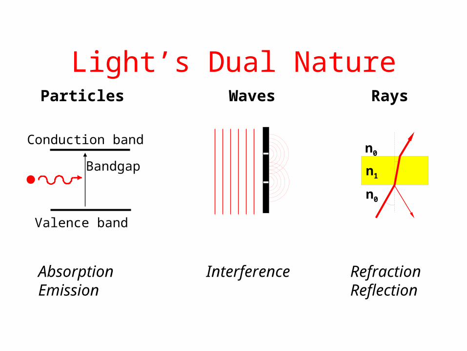
Light’s Dual NatureRaysWavesParticles
AbsorptionEmission
Interference RefractionReflection
Bandgap
Conduction band
Valence band
n0
n1
n0

Why Optical ?
• High Bandwidth ( 500 Tbps)• Low Attenuation (.25 dB/km)• Low BER (10 -13) • Light and occupies lesser space• Flexible and Reliable• Less crosstalk due to neutral photons• Hard to eavesdrop• Environmentally sound.

Bandwidth Comparison
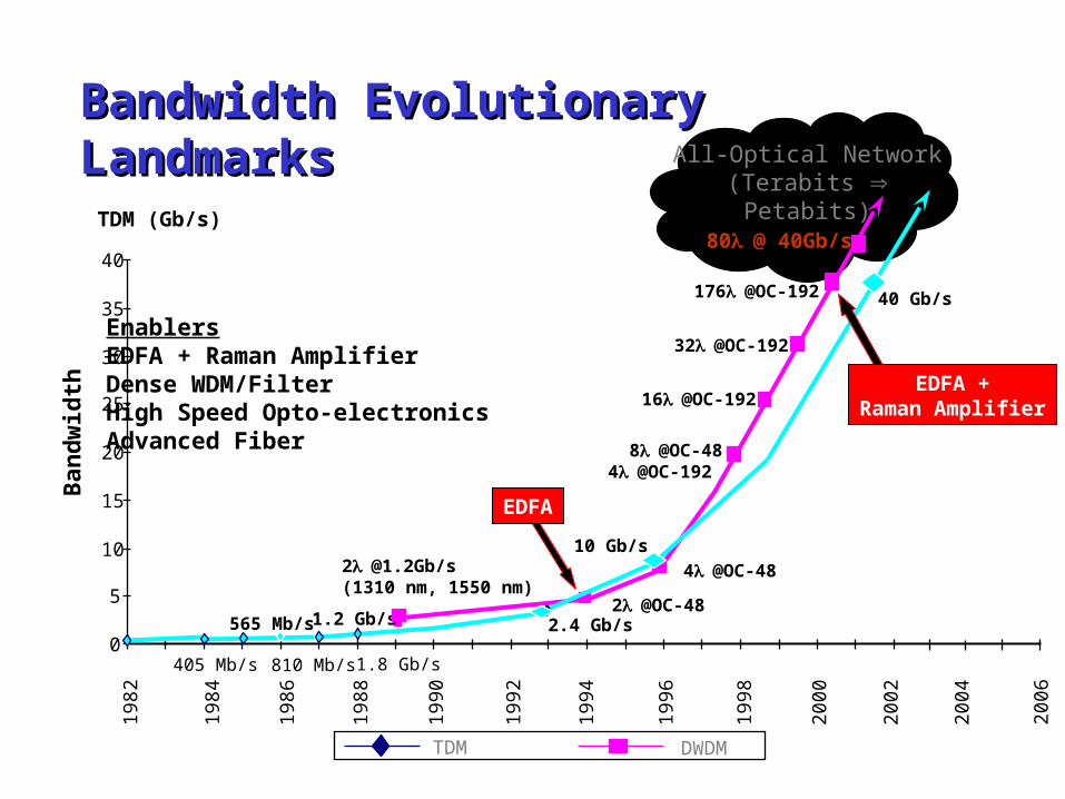
All-Optical Network(Terabits Petabits)
TDM DWDM
0
5
10
15
20
25
30
35
40
Ban
dw
idth
8@OC-484@OC-192
4@OC-48
2@OC-48
[email protected]/s(1310 nm, 1550 nm)
10 Gb/s
2.4 Gb/s1.2 Gb/s565 Mb/s
1.8 Gb/s810 Mb/s405 Mb/s
EnablersEDFA + Raman AmplifierDense WDM/FilterHigh Speed Opto-electronicsAdvanced Fiber
1982
1984
1988
1994
1996
1998
2000
2002
1990
1986
1992
16@OC-192
40 Gb/s
32@OC-192
176@OC-192
2004
2006
TDM (Gb/s)
EDFA
EDFA +Raman Amplifier
80@ 40Gb/s
Bandwidth Evolutionary LandmarksBandwidth Evolutionary Landmarks
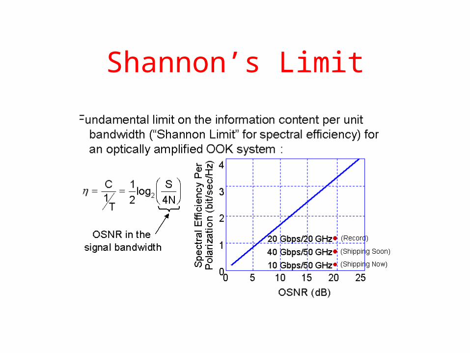
Shannon’s Limit
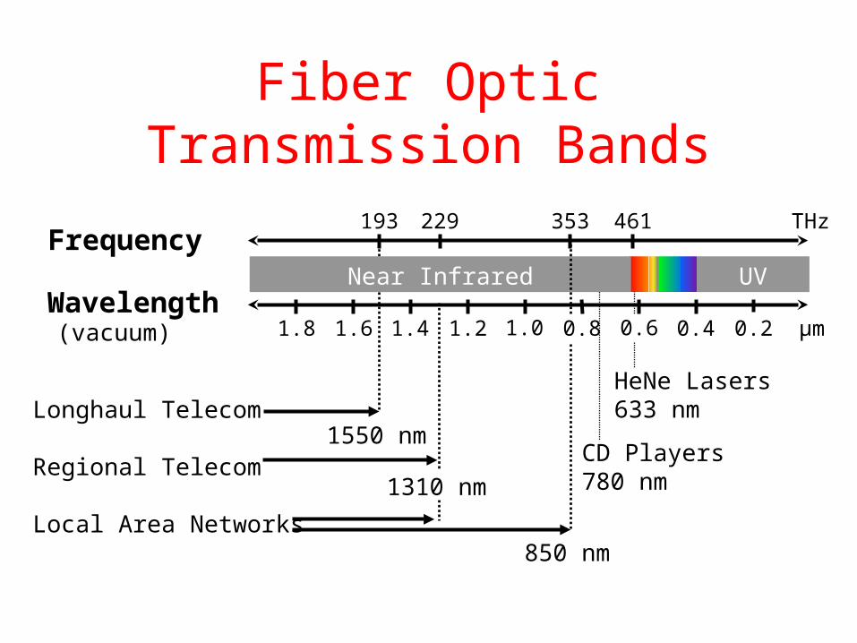
Fiber Optic Transmission Bands
Near Infrared
Frequency
Wavelength1.6
229
1.0 0.8 µm0.6 0.41.8 1.4
UV
(vacuum) 1.2
THz193 461
0.2
353
Longhaul Telecom
Regional Telecom
Local Area Networks850 nm
1550 nm
1310 nmCD Players780 nm
HeNe Lasers633 nm

Optical Components
1. The Fiber A. Total Internal Reflection B. Multi Mode Fiber C. Single Mode Fiber D. Transmission Impairments Loss a. Rayleigh scattering b. Reflection c. Absorption Dispersion a. Chromatic Dispersion 1. Material Dispersion 2. Waveguide Dispersion b. Polarization Mode Dispersion Non-Linearities a. Stimulated Raman Scattering b. Stimulated Brillouin Scattering c. Four Wave Mixing d. Self Phase Modulation e. Cross Phase Modulation

Optical Components (Contd)
2. Couplers3. Isolators 4. Circulators5. Filters A. Diffraction Grating B. Reflection Grating C. Fabry Perot Filter D. Thin Film Dielectric Filter. E. Bragg Grating a. Short Period fiber bragg grating b. Long Period fiber bragg grating F. Mac Zhender Interferometer G. Arrayed Waveguide Grating H. Acoustoptic Tunable Filter

Optical Components (Contd)
6. Optical Amplifers A. Erbium Doped Fiber Amplifiers (EDFA) B. Raman Amplifiers (RA) C. Semiconductor Optical Amplifier (SOA)7. Lasers A. MLM Fabry Perot B. Single Mode Lasers a. Distributed Bragg Reflector Laser (DBR) b. Distributed Feedback Laser (DFB) c. External Cavity Lasers8. Modulators9. Detectors A. PIN B. APD
Optical Components (Contd)
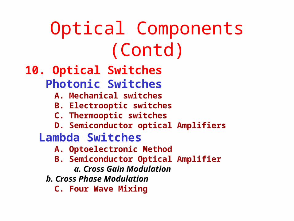
10. Optical Switches Photonic Switches A. Mechanical switches B. Electrooptic switches C. Thermooptic switches D. Semiconductor optical Amplifiers
Lambda Switches A. Optoelectronic Method B. Semiconductor Optical Amplifier a. Cross Gain Modulation b. Cross Phase Modulation C. Four Wave Mixing

An Optical Network
Dispersion Managed FiberMedium Dispersion Fiber
Tx
Tx
TxWDM
OA
Tunable DCM
OA
DCFTunable DCM
DWDM
DynamicPMD Compensation
New Modulation Formats Forward Error Correction
ImpairmentTolerantReceiver
C+L Band OAS Band OA
Raman AmplifierDynamic OADM
. . . .
.
3000Km - 5000Km
Rx
Rx
Rx
PMDC
PMDC
PMDCBroadband
PMD Compensation

1. The Fiber
Glass n = 1.5
Air n = 1.0
Light at thisangle is refracted
Light at this angle isreflected back into glass1 2
1 = 2 For Total Internal Reflection
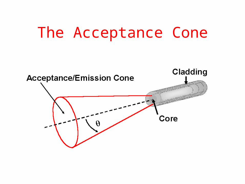
The Acceptance Cone
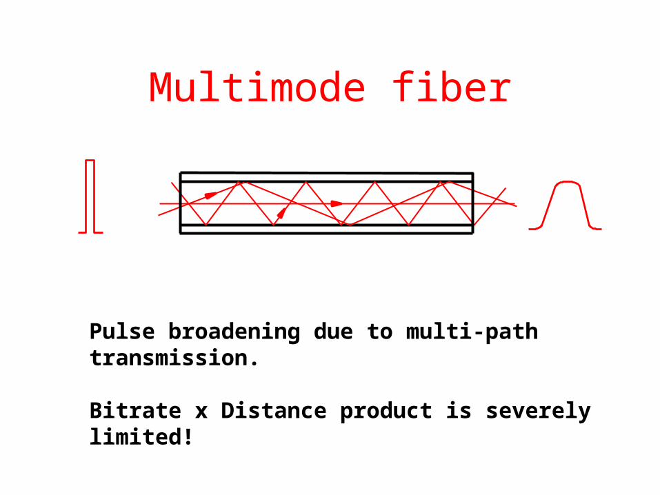
Multimode fiber
Pulse broadening due to multi-path transmission.
Bitrate x Distance product is severely limited!

Doping profile designed to minimize “race” conditions(“outer” modes travel faster due to lower refractive index!)
Most common designs: 62.5/125 or 50/125 m, NA ~ 0.2Bitrate x Distance product: ~ 1 Gb/s • km
r
Gradient-Index (GI) Fiber

Step-Index type with very small core
Single-Mode Fiber (SMF)
n
r
1.465
1.460

Transmission Impairments

Rayleigh Scattering

Reflection

Absorption

Transmission Impairments
900 1100 1300 1500 1700
0.5
1.0
1.5
2.0
2.5
OH Absorption
Att
en
uati
on
(d
B/k
m)
Wavelength (nm)
“Optical Windows” 2 3
1
Main cause of attenuation: Rayleigh scattering in the fiber core
45
AllWaveTM eliminatesthe 1385nm water peak
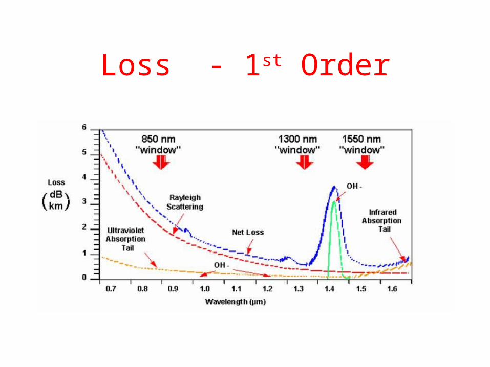
Loss - 1st Order

Chromatic Dispersion
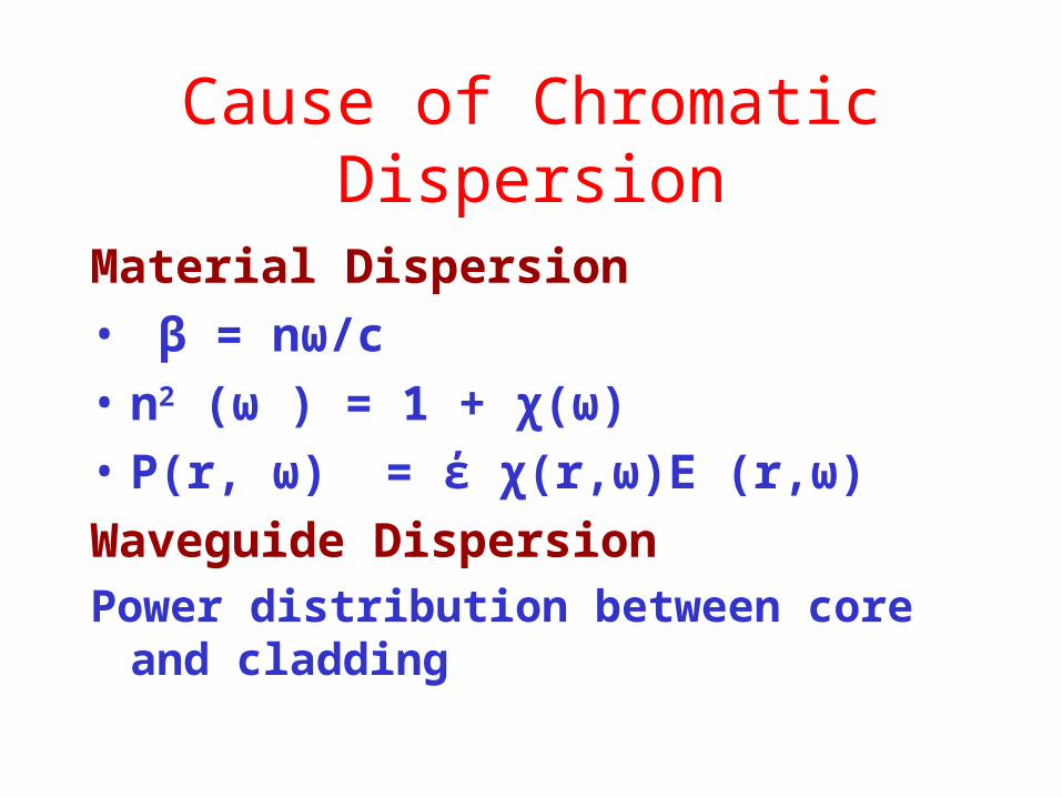
Cause of Chromatic Dispersion
Material Dispersion
• β = nω/c
• n2 (ω ) = 1 + χ(ω)
• P(r, ω) = έ χ(r,ω)E (r,ω)
Waveguide DispersionPower distribution between core and cladding

Dispersion Limits
Dispersion Compensation
• Dispersion Compensation Fiber
• Fiber Bragg Gratings

Polarization Mode Dispersion
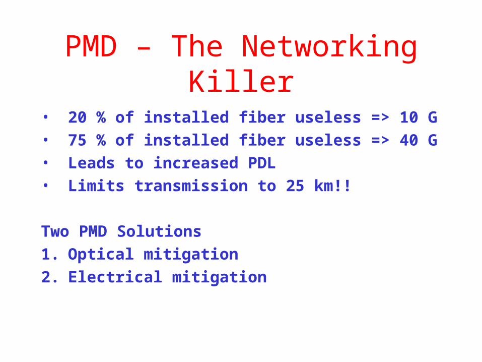
PMD – The Networking Killer
• 20 % of installed fiber useless => 10 G• 75 % of installed fiber useless => 40 G• Leads to increased PDL• Limits transmission to 25 km!!
Two PMD Solutions
1. Optical mitigation
2. Electrical mitigation

PMD Compensation
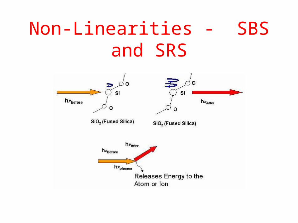
Non-Linearities - SBS and SRS

Cause of Non-Linearity
P = έ [ χ1. E + χ 2. E.E + χ3.E.E.E +…]
For high values of E, the third order term
becomes significant.

Scattering Compensation
Ways to reduce SBS penalty
• Power below threshold
• Increase line width of the source
• Use Phase modulation schemes
Ways to reduce SRS penalty
• Keep the channels densely packed
• Keep power below threshold.

Four Wave Mixing
FWM Compensation
• Unequal channel spacing
• Increased channel spacing
• Reduced power below threshold
• Use spatial walk off – introduce time delay
Non-Linearties (Contd)
• Self Phase Modulation
Refractive index dependance on the power
of a signal
• Cross Phase Modulation
Refractive index dependance on the power
of another signal

Effects of Nonlinearites

Multiple Channels vs Single Channel
Tools to combat Impairments
• Power / Channel
• Dispersion Compensation
• Channel Spacing
• Wavelength / Frequency Choice
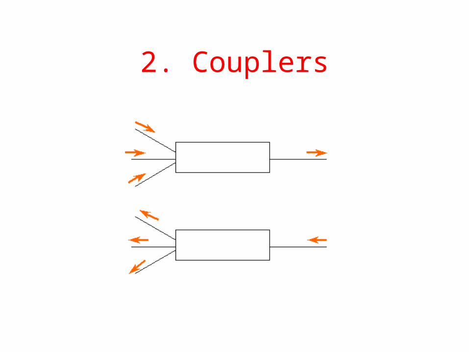
2. Couplers
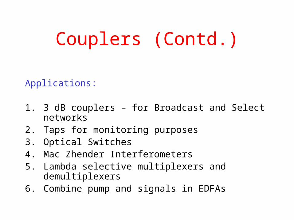
Couplers (Contd.)
Applications:
1. 3 dB couplers – for Broadcast and Select networks2. Taps for monitoring purposes3. Optical Switches 4. Mac Zhender Interferometers5. Lambda selective multiplexers and demultiplexers6. Combine pump and signals in EDFAs
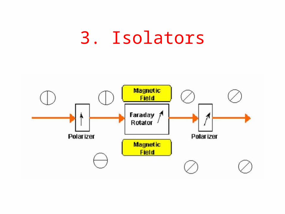
3. Isolators

4. Circulators

5. Filters
Fabry Perot Filter

Diffraction Grating

Bragg Grating

Mac Zhender Grating

Thin Film Dielectric Grating
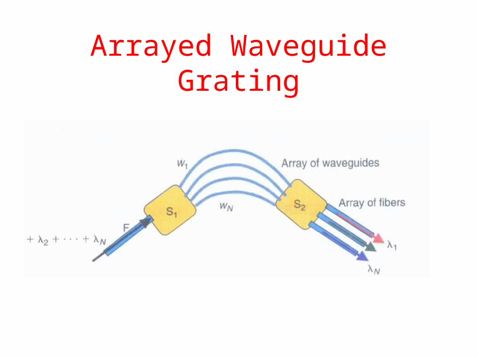
Arrayed Waveguide Grating
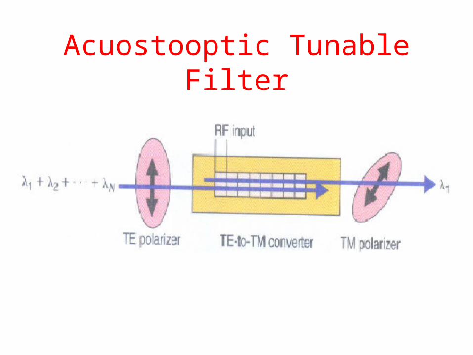
Acuostooptic Tunable Filter
6. Optical Amplifiers
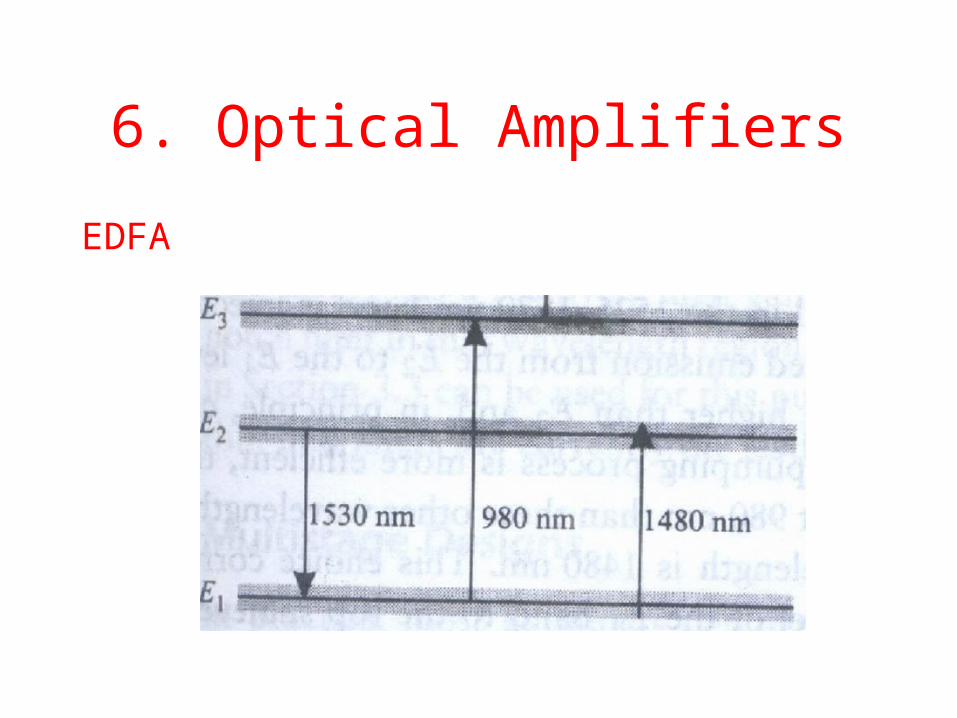
EDFA
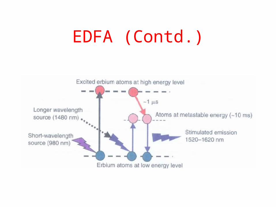
EDFA (Contd.)

EDFA (Contd.)

SNR

All Optical System Capacity
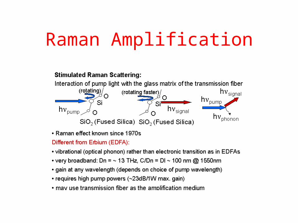
Raman Amplification

Raman Amplifiers
Used as Pre-amplifier in the reverse direction
• Same pump laser as EDFA
• Higher gains
• Larger Bandwidth
• Distributed and hence lower noise figure’
• Lower Plaunched – reduced nonlinearities

Benefits of Raman

Semiconductor Optical Amplifier
7. Lasers
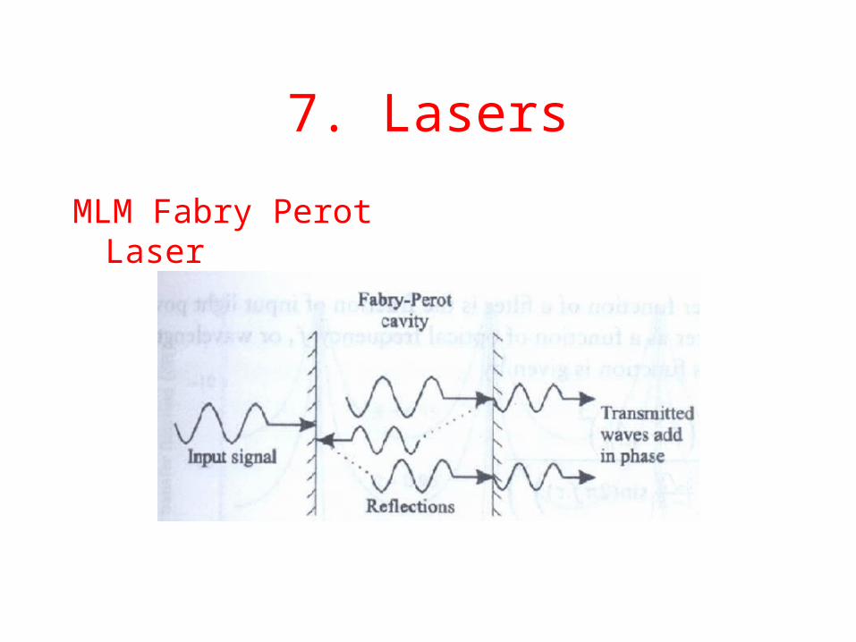
MLM Fabry Perot Laser

SLM Lasers
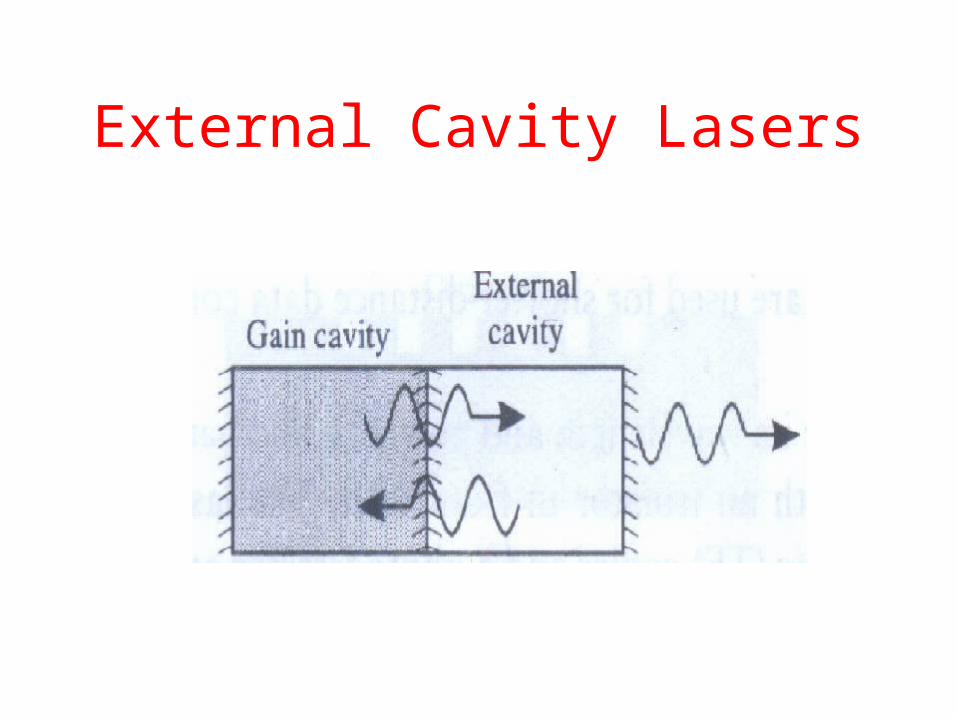
External Cavity Lasers
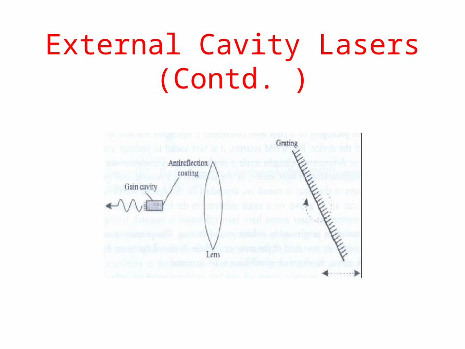
External Cavity Lasers (Contd. )

8. External Modulators

9. Photodetectors

A Photodiode

10. Optical Switches
• Photonic Switches (MEMS)

Electrooptic Switch

Lamda Switch

An Optical Network - Revisited
Dispersion Managed FiberMedium Dispersion Fiber
Tx
Tx
TxWDM
OA
Tunable DCM
OA
DCFTunable DCM
DWDM
DynamicPMD Compensation
New Modulation Formats Forward Error Correction
ImpairmentTolerantReceiver
C+L Band OAS Band OA
Raman AmplifierDynamic OADM
. . . .
.
3000Km - 5000Km
Rx
Rx
Rx
PMDC
PMDC
PMDCBroadband
PMD Compensation

Conclusion


