General rights Copyright and moral rights for the publications made accessible in the public portal are retained by the authors and/or other copyright owners and it is a condition of accessing publications that users recognise and abide by the legal requirements associated with these rights.
• Users may download and print one copy of any publication from the public portal for the purpose of private study or research. • You may not further distribute the material or use it for any profit-making activity or commercial gain • You may freely distribute the URL identifying the publication in the public portal
If you believe that this document breaches copyright please contact us providing details, and we will remove access to the work immediately and investigate your claim.
Downloaded from orbit.dtu.dk on: Dec 17, 2017
Optical Packet Switching Demostrator
Mortensen, Brian Bach; Berger, Michael Stübert
Published in:28th European Conference on Optical Communication, 2002. ECOC 2002.
Link to article, DOI:10.1109/ECOC.2002.204435
Publication date:2002
Document VersionPublisher's PDF, also known as Version of record
Link back to DTU Orbit
Citation (APA):Mortensen, B. B., & Berger, M. S. (2002). Optical Packet Switching Demostrator. In 28th European Conferenceon Optical Communication, 2002. ECOC 2002. (Vol. 2, pp. 1-2). IEEE. DOI: 10.1109/ECOC.2002.204435
Symposium 2.6
OPTICAL PACKET SWITCHING DEMOSTRATOR
Brian Bach Mortensen (1), Michael StObert Berger (2)Research Center COM, DTU building 343, 125, 2800 Lyngby, Denmark, [email protected]
Research Center COM, [email protected]
Abstract In the IST project DAVID (Data And Voice Integration over DWDM) work is carried out defining possiblearchitectures of future optical packet switched networks. The feasibility of the architecture is to be verified in ademonstration set-up. This article describes the demonstrator set-up and the measurement metrics that will beused to evaluate the demonstrator.
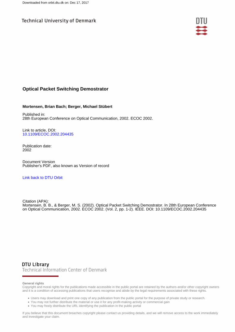
IntroductionThe network studied in the DAVID project is dividedinto a backbone or core part (hereafter WAN) and anaccess metropolitan area network (hereafter MAN).The WAN network topology is mesh-based and theMAN network is ring-based. See figure 1.0=m l 5 e S .g2%S.L5, W
Figure 1 The DAVID network concept
Both networks operate in a time slotted approach,with optical packet lengths of 1 us. In addition to this,DWDM is also used to provide a large amount ofbandwidth between the nodes. The optical packets inboth MAN and WAN are divided into a header and apayload that can operate a various bit rates.In the MAN physically disjointed rings are connectedthrough a HUB that consists of an optical spaceswitch with no internal buffer capacity. Each ringcarries multiple wavelengths of which one isdedicated to transport control data (Media AccessControl, MAC) for all the ring nodes. The MACchannel informs each ring node whether is can senda packet or if it has to receive the packets arfiving inthe following timeslot. The space permutations of theHUB are announced on the MAC channel as well,such that the ring nodes can determine if they havetraffic destined for one of the possible rings in thefollowing timeslot. The MAC part of the project areamong others studied in [1][2]. At each ring node anumber of IP routers are connected providing accessto legacy/enterprise networks.In the WAN, packets are switched transparentlythrough the optical packet routers. Since traffic is notscheduled globally among the OPRs (Optical Packetswitched Router) the switch nodes need to have
buffering capabilities in order to solve outputcontention. The bandwidth defined for the WAN is40Gb/s compared to 10Gb/s for the MAN.The WAN and MAN are connected through a gatewaywhich adapts both between bandwidths and packetformats.Motivation for the DAVID demonstratorThe main objectives of building the demonstrator arelisted below:
1. Test of the WAN concept, implementingoptical packet switching.
2. Test of the MAN concept, implementing amulti-ring multi-QoS packet switched ring.
3. Test of the interconnection between theMAN and the WAN, providing packetadaptation and buffering.
4. Verification of the physical feasibility, opticalsynchronization and regeneration.
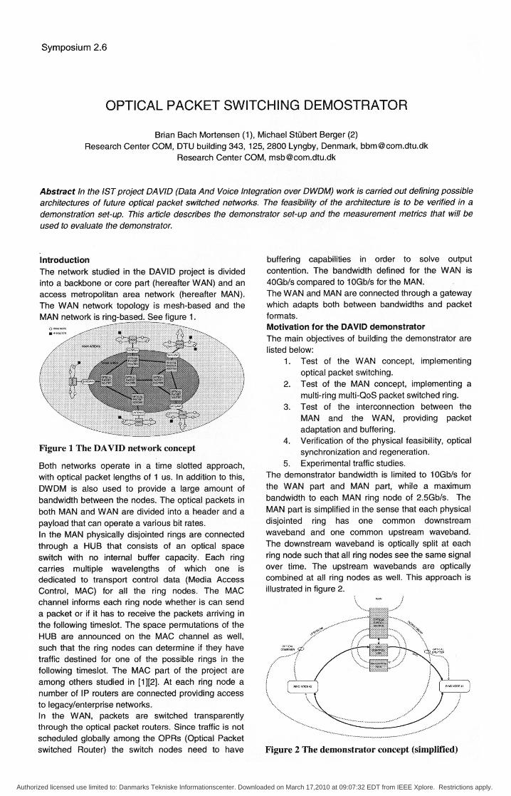
5. Experimental traffic studies.The demonstrator bandwidth is limited to 10Gb/s forthe WAN part and MAN part, while a maximumbandwidth to each MAN ring node of 2.5Gb/s. TheMAN part is simplified in the sense that each physicaldisjointed ring has one common downstreamwaveband and one common upstream waveband.The downstream waveband is optically split at eachring node such that all ring nodes see the same signalover time. The upstream wavebands are opticallycombined at all ring nodes as well. This approach isillustrated in figure 2.
Figure 2 The demonstrator concept (simplified)
Authorized licensed use limited to: Danmarks Tekniske Informationscenter. Downloaded on March 17,2010 at 09:07:32 EDT from IEEE Xplore. Restrictions apply.
Symposium 2.6
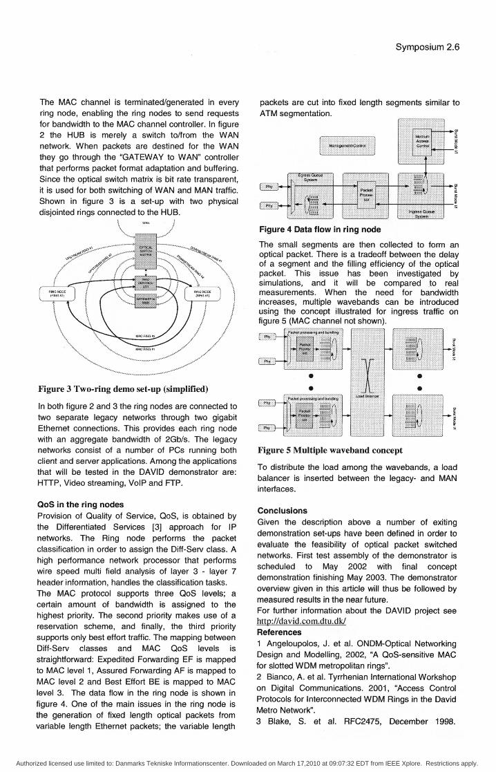
The MAC channel is terminated/generated in everyring node, enabling the ring nodes to send requestsfor bandwidth to the MAC channel controller. In figure2 the HUB is merely a switch to/from the WANnetwork. When packets are destined for the WANthey go through the 'GATEWAY to WAN" controllerthat performs packet format adaptation and buffering.Since the optical switch matrix is bit rate transparent,it is used for both switching of WAN and MAN traffic.Shown in figure 3 is a set-up with two physicaldisjointed rings connected to the HUB.
packets are cut into fixed length segments similar toATM segmentation.
- Nti: .Oo
LED. -~F
I
Figure 4 Data flow in ring nodeThe small segments are then collected to form anoptical packet. There is a tradeoff between the delayof a segment and the filling efficiency of the opticalpacket. This issue has been investigated bysimulations, and it will be compared to realmeasurements. When the need for bandwidthincreases, multiple wavebands can be introducedusing the concept illustrated for ingress traffic onfigure 5 (MAC channel not shown).
Figure 3 Two-ring demo set-up (simplified)
In both figure 2 and 3 the ring nodes are connected totwo separate legacy networks through two gigabitEthemet connections. This provides each ring nodewith an aggregate bandwidth of 2Gb/s. The legacynetworks consist of a number of PCs running bothclient and server applications. Among the applicationsthat will be tested in the DAVID demonstrator are:HTTP, Video streaming, VolP and FTP.
QoS in the ring nodesProvision of Quality of Service, QoS, is obtained bythe Differentiated Services [3] approach for IPnetworks. The Ring node performs the packetclassification in order to assign the Diff-Serv class. Ahigh performance network processor that performswire speed multi field analysis of layer 3 - layer 7header information, handles the classiication tasks.The MAC protocol supports three QoS levels; acertain amount of bandwidth is assigned to thehighest priority. The second priority makes use of areservation scheme, and finally, the third prioritysupports only best effort traffic. The mapping betweenDiff-Serv classes and MAC QoS levels isstraighfforward: Expedited Forwarding EF is mappedto MAC level 1, Assured Forwarding AF is mapped toMAC level 2 and Best Effort BE is mapped to MAClevel 3. The data flow in the ring node is shown infigure 4. One of the main issues in the ring node isthe generation of fixed length optical packets fromvariable length Ethernet packets; the variable length
a0
U
S
43I
Figure 5 Multiple waveband concept
To distribute the load among the wavebands, a loadbalancer is inserted between the legacy- and MANinterfaces.
ConclusionsGiven the description above a number of exitingdemonstration set-ups have been defined in order toevaluate the feasibility of optical packet switchednetworks. First test assembly of the demonstrator isscheduled to May 2002 with final conceptdemonstration finishing May 2003. The demonstratoroverview given in this article will thus be followed bymeasured results in the near future.For further information about the DAVID project seehttp://david.com.dtu.dk/References1 Angeloupolos, J. et al. ONDM-Optical NetworkingDesign and Modelling, 2002, "A QoS-sensitive MACfor slotted WDM metropolitan rings".2 Bianco, A. et al. Tyrrhenian International Workshopon Digital Communications. 2001, "Access ControlProtocols for Interconnected WDM Rings in the DavidMetro Network.3 Blake, S. et al. RFC2475, December 1998.
Authorized licensed use limited to: Danmarks Tekniske Informationscenter. Downloaded on March 17,2010 at 09:07:32 EDT from IEEE Xplore. Restrictions apply.


