
OPTIBAR ACCESSORIESOPTIBAR ACCESSORIESOPTIBAR ACCESSORIESOPTIBAR ACCESSORIES Technical DatasheetTechnical DatasheetTechnical DatasheetTechnical Datasheet
Accessories for OPTIBAR pressure transmitter
• Valves and manifolds• Flange adapter• Condensate pots• Connecting pipes and other accessories
© KROHNE 10/2014 - 4003910401 - TD OPTIBAR Accessories R01 en

CONTENTS
2 www.krohne.com 10/2014 - 4003910401 - TD OPTIBAR Accessories R01 en
OPTIBAR ACCESSORIES
1 Valves 4
1.1 Manometer valve .............................................................................................................. 41.2 Ordering information for manometer valves ................................................................... 81.3 Barstock valves ................................................................................................................ 91.4 Ordering information for barstock valves...................................................................... 131.5 Valve accessories ........................................................................................................... 14
2 Manifolds 15
2.1 Manifolds ........................................................................................................................ 152.2 Ordering information for manifolds ............................................................................... 202.3 Manifolds for steam and HT steam................................................................................ 212.4 Ordering information for manifolds for steam and HT steam....................................... 262.5 Manifold accessories...................................................................................................... 27
3 Flange adapter 29
3.1 Versions of flange adapter ............................................................................................. 293.2 Ordering information for flange adapter ....................................................................... 30
4 Condensate pots 31
4.1 Versions of condensate pot ............................................................................................ 314.2 Ordering information for condensate pots .................................................................... 34
5 Connecting pipes 35
5.1 Connecting pipes and syphons....................................................................................... 355.1.1 Straight and curved connecting pipes .................................................................................. 385.1.2 Syphons in U shape............................................................................................................... 395.1.3 Syphons in circular shape..................................................................................................... 405.1.4 Syphons ................................................................................................................................. 41
5.2 Ordering information for connecting pipes and syphons .............................................. 42
6 General accessories 43
6.1 Fittings – female and male............................................................................................. 436.2 Ordering information for fittings.................................................................................... 446.3 Sealing o-ring acc. to EN 837-1 ..................................................................................... 456.4 Blind plug........................................................................................................................ 456.5 Oval flange adapter ........................................................................................................ 466.6 Gauge snubber ............................................................................................................... 47

CONTENTS
3www.krohne.com10/2014 - 4003910401 - TD OPTIBAR Accessories R01 en
OPTIBAR ACCESSORIES
7 Appendix 48
7.1 Typical measurement setups (hook-ups) ...................................................................... 487.1.1 Pressure measurement – Direct mounting – Gaseous ....................................................... 487.1.2 Pressure measurement – Direct mounting – Gaseous/liquid ............................................. 507.1.3 Pressure measurement – Direct mounting – Liquid/vaporous ........................................... 517.1.4 Pressure measurement – Direct mounting – Vaporous ...................................................... 527.1.5 Differential pressure measurement – Direct mounting – Gaseous .................................... 547.1.6 Differential pressure measurement – Rack mounting – Gaseous ...................................... 557.1.7 Differential pressure measurement – Rack mounting – Liquid .......................................... 567.1.8 Differential pressure measurement – Rack mounting – Vaporous..................................... 57
7.2 Material designations..................................................................................................... 58
8 Notes 59

1 VALVES
4
OPTIBAR ACCESSORIES
www.krohne.com 10/2014 - 4003910401 - TD OPTIBAR Accessories R01 en
1.1 Manometer valve
Manometer valves are mounted as shut-off valves in front of pressure gauges with and without test connection. A test connection later allows a simple check of the measuring device.
All manometer valves are designed for a nominal pressure of 400 bar / 5801 psi.Valves with PN640 are available on request. The valve body is die forged. The steel surface is phosphated.
1 Cleaned and degreased version for oxygen is available on request.
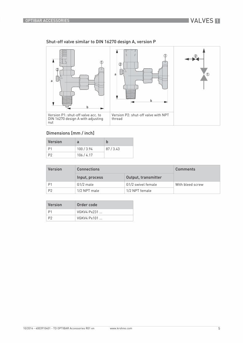
Shut-off valve similar to DIN 16270 design A, version P
Shut-off valve acc. to DIN 16270 design B with swivel female and mounting bracket, version M1
Shut-off valve acc. to DIN 16271 design B with swivel female and mounting bracket and test connection, version M2
Shut-off valve acc. to DIN 16272 design B with swivel female, shaft and remote lockable test connection M20x1.5, version N
Individual parts Steel Stainless steel 1
Housing 1.0460 / C22.8-10...+120°C / +14...+248°F
1.4571 / 316Ti-20...+200/250°C /-4...+392/482°F
Valve stem, valve needle 1.4104 / 430F 1.4571 / 316Ti
Packing PTFE up to +200°C / +392°F
Union nut, females, bleed screw Steel Stainless steel
Handwheel Plastic
VALVES 1
5
OPTIBAR ACCESSORIES
www.krohne.com10/2014 - 4003910401 - TD OPTIBAR Accessories R01 en
Shut-off valve similar to DIN 16270 design A, version P
Dimensions [mm / inch]
Version P1: shut-off valve acc. to DIN 16270 design A with adjusting nut
Version P2: shut-off valve with NPT thread
Version a b
P1 100 / 3.94 87 / 3.43
P2 106 / 4.17
Version Connections Comments
Input, process Output, transmitter
P1 G1/2 male G1/2 swivel female With bleed screw
P2 1/2 NPT male 1/2 NPT female
Version Order code
P1 VGKV4 Px231 ...
P2 VGKV4 Px101 ...

1 VALVES
6
OPTIBAR ACCESSORIES
www.krohne.com 10/2014 - 4003910401 - TD OPTIBAR Accessories R01 en
Shut-off valve acc. to DIN 16270 and DIN 16271 design B with swivel female and mounting bracket, version M
Dimensions [mm / inch]
Version M1: shut-off valve acc. to DIN 16270 design B Version M2: shut-off valve acc. to DIN 16271 design B with test connection
a b
125 / 4.92 87 / 3.43
Version Connections Comments
Input, process Output, transmitter
M1 G1/2 male G1/2 swivel female With bleed screw
M2 With bleed screw and test connection M20x1.5
Version Order code
M1 VGKV4 Mx231 ...
M2 VGKV4 Mx23M ...

VALVES 1
7
OPTIBAR ACCESSORIES
www.krohne.com10/2014 - 4003910401 - TD OPTIBAR Accessories R01 en
Shut-off valve acc. to DIN 16272 design B with swivel female, shaft and remote lockable test connection M20x1.5, version N
Dimensions [mm / inch]
Ordering information for separate mounting brackets
Version N: shut-off valve acc. to DIN 16272 design B with swivel female, shaft and remote lockable test connection M20x1.5
a b
125 / 4.92 190 / 7.48
Version Connections Comments
Input, process Output, transmitter
N G1/2 male G1/2 swivel female With test connection M20x1.5
Version Order code
N VGKV4 Nx23M ...
Item number Item
XGKV5 12201 Mounting brackets made of stainless steel for manometer valves design B, wall mounting and 2" pipe mounting
1 VALVES
8
OPTIBAR ACCESSORIES
www.krohne.com 10/2014 - 4003910401 - TD OPTIBAR Accessories R01 en
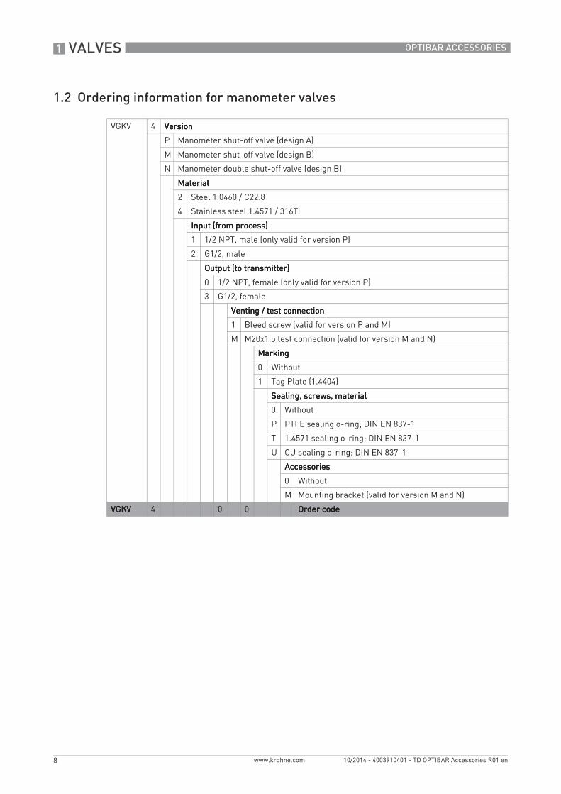
1.2 Ordering information for manometer valves
VGKV 4 VersionVersionVersionVersion
P Manometer shut-off valve (design A)
M Manometer shut-off valve (design B)
N Manometer double shut-off valve (design B)
MaterialMaterialMaterialMaterial
2 Steel 1.0460 / C22.8
4 Stainless steel 1.4571 / 316Ti
Input (from process)Input (from process)Input (from process)Input (from process)
1 1/2 NPT, male (only valid for version P)
2 G1/2, male
Output (to transmitter)Output (to transmitter)Output (to transmitter)Output (to transmitter)
0 1/2 NPT, female (only valid for version P)
3 G1/2, female
Venting / test connectionVenting / test connectionVenting / test connectionVenting / test connection
1 Bleed screw (valid for version P and M)
M M20x1.5 test connection (valid for version M and N)
MarkingMarkingMarkingMarking
0 Without
1 Tag Plate (1.4404)
Sealing, screws, materialSealing, screws, materialSealing, screws, materialSealing, screws, material
0 Without
P PTFE sealing o-ring; DIN EN 837-1
T 1.4571 sealing o-ring; DIN EN 837-1
U CU sealing o-ring; DIN EN 837-1
AccessoriesAccessoriesAccessoriesAccessories
0 Without
M Mounting bracket (valid for version M and N)
VGKVVGKVVGKVVGKV 4 0 0 Order codeOrder codeOrder codeOrder code

VALVES 1
9
OPTIBAR ACCESSORIES
www.krohne.com10/2014 - 4003910401 - TD OPTIBAR Accessories R01 en
1.3 Barstock valves
Barstock valves are mounted as shut-off valves in front of pressure gauges. They are designed as single or double valves.
All barstock valves are designed for a nominal pressure of PN420/DN5. The valve housing is formed from bar stock. All connection threads are designed as male and female threads. All valves are made from the material 1.4404 / 316L.
Single shut-off valve, version 0 Block & bleed valve, version 1 Block & bleed valve in compact version, version 2
Individual parts Material Special features
Housing 1.4404 / 316L • External stem thread• Cold rolled valve stem with back
seat and crimped valve needle• Anti tamper head (optional)
Stem guide 1.4401 / 316
Valve stem 1.4404 / 316L
Valve needle 1.4571 / 316Ti
Packing PTFE up to +200°C / +392°FPure graphite up to +550°C / +1022°F
Stem nut 1.4301
T-handle Stainless steel
Pressure/temperature rating (pressure p in bar and psi; temperature T in °C and °F)
1 PTFE packing2 Pure graphite packing
1 VALVES
10
OPTIBAR ACCESSORIES
www.krohne.com 10/2014 - 4003910401 - TD OPTIBAR Accessories R01 en
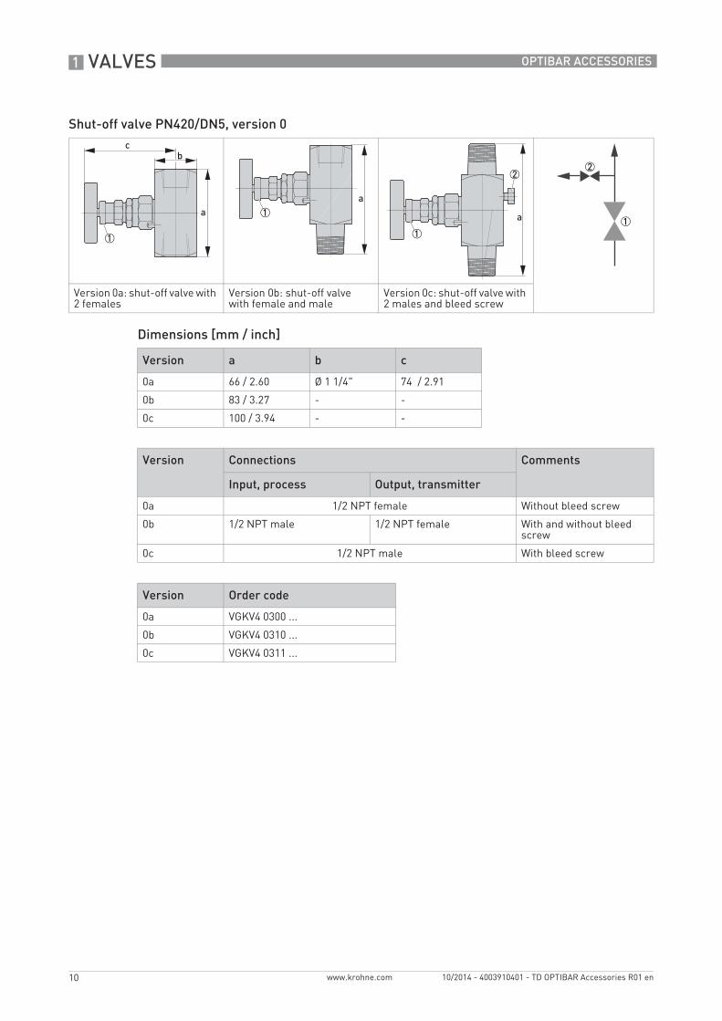
Shut-off valve PN420/DN5, version 0
Dimensions [mm / inch]
Version 0a: shut-off valve with 2 females
Version 0b: shut-off valve with female and male
Version 0c: shut-off valve with 2 males and bleed screw
Version a b c
0a 66 / 2.60 Ø 1 1/4" 74 / 2.91
0b 83 / 3.27 - -
0c 100 / 3.94 - -
Version Connections Comments
Input, process Output, transmitter
0a 1/2 NPT female Without bleed screw
0b 1/2 NPT male 1/2 NPT female With and without bleed screw
0c 1/2 NPT male With bleed screw
Version Order code
0a VGKV4 0300 ...
0b VGKV4 0310 ...
0c VGKV4 0311 ...

VALVES 1
11
OPTIBAR ACCESSORIES
www.krohne.com10/2014 - 4003910401 - TD OPTIBAR Accessories R01 en
Block & bleed valve, PN420/DN5, version 1
Dimensions [mm / inch]
Version 1a: block & bleed valve with male and female and bleed screw
Version 1b: block & bleed valve with 2 females and bleed screw
Version a b c
1a 114 / 4.49 - -
1b 97 / 3.82 Ø 1 1/4" 148 / 5.83
Version Connections Comments
Input, process Output, transmitter
1a 1/2 NPT male 1/2 NPT female 1/4 NPT female with screw plug for testing/venting
1b 1/2 NPT female
1c 1/2 NPT female 1/2 NPT male
1d 1/2 NPT male
Version Order code
1a VGKV4 1310 ...
1b VGKV4 1300 ...
1c VGKV4 1301 ...
1d VGKV4 1311 ...
1 VALVES
12
OPTIBAR ACCESSORIES
www.krohne.com 10/2014 - 4003910401 - TD OPTIBAR Accessories R01 en
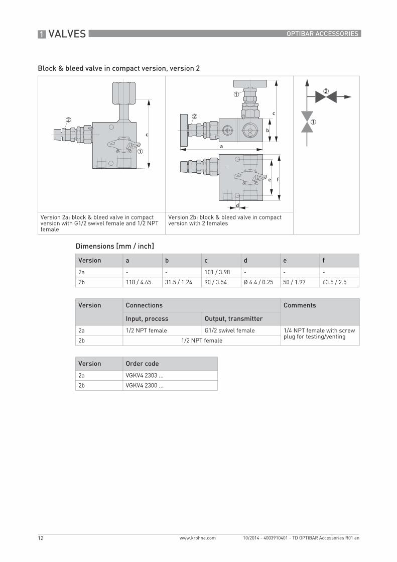
Block & bleed valve in compact version, version 2
Dimensions [mm / inch]
Version 2a: block & bleed valve in compact version with G1/2 swivel female and 1/2 NPT female
Version 2b: block & bleed valve in compact version with 2 females
e f
Version a b c d e f
2a - - 101 / 3.98 - - -
2b 118 / 4.65 31.5 / 1.24 90 / 3.54 Ø 6.4 / 0.25 50 / 1.97 63.5 / 2.5
Version Connections Comments
Input, process Output, transmitter
2a 1/2 NPT female G1/2 swivel female 1/4 NPT female with screw plug for testing/venting
2b 1/2 NPT female
Version Order code
2a VGKV4 2303 ...
2b VGKV4 2300 ...
VALVES 1
13
OPTIBAR ACCESSORIES
www.krohne.com10/2014 - 4003910401 - TD OPTIBAR Accessories R01 en
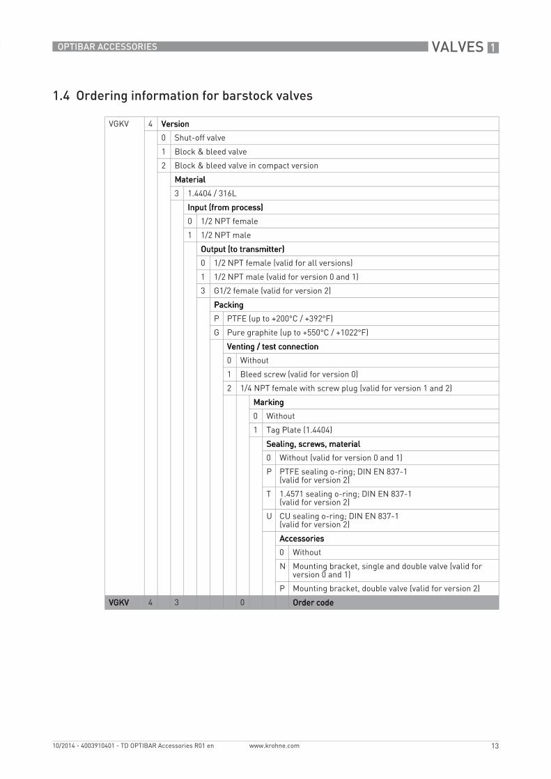
1.4 Ordering information for barstock valves
VGKV 4 VersionVersionVersionVersion
0 Shut-off valve
1 Block & bleed valve
2 Block & bleed valve in compact version
MaterialMaterialMaterialMaterial
3 1.4404 / 316L
Input (from process)Input (from process)Input (from process)Input (from process)
0 1/2 NPT female
1 1/2 NPT male
Output (to transmitter)Output (to transmitter)Output (to transmitter)Output (to transmitter)
0 1/2 NPT female (valid for all versions)
1 1/2 NPT male (valid for version 0 and 1)
3 G1/2 female (valid for version 2)
PackingPackingPackingPacking
P PTFE (up to +200°C / +392°F)
G Pure graphite (up to +550°C / +1022°F)
Venting / test connectionVenting / test connectionVenting / test connectionVenting / test connection
0 Without
1 Bleed screw (valid for version 0)
2 1/4 NPT female with screw plug (valid for version 1 and 2)
MarkingMarkingMarkingMarking
0 Without
1 Tag Plate (1.4404)
Sealing, screws, materialSealing, screws, materialSealing, screws, materialSealing, screws, material
0 Without (valid for version 0 and 1)
P PTFE sealing o-ring; DIN EN 837-1(valid for version 2)
T 1.4571 sealing o-ring; DIN EN 837-1(valid for version 2)
U CU sealing o-ring; DIN EN 837-1(valid for version 2)
AccessoriesAccessoriesAccessoriesAccessories
0 Without
N Mounting bracket, single and double valve (valid for version 0 and 1)
P Mounting bracket, double valve (valid for version 2)
VGKVVGKVVGKVVGKV 4 3 0 Order codeOrder codeOrder codeOrder code

1 VALVES
14
OPTIBAR ACCESSORIES
www.krohne.com 10/2014 - 4003910401 - TD OPTIBAR Accessories R01 en
1.5 Valve accessories
Mounting brackets
Dimensions [mm / inch]
A mounting bracket set contains:• Mounting bracket made of stainless steel• U retaining clamp• Washers Ø 8.4 mm / 0.33"• Hexagon nut, M8• Screws for mounting the manifold on the bracket where necessary.
Ordering information for separate mounting brackets
Mounting brackets for shut-off valves, design 1 to 3 with square 1 1/4" valve body
Mounting brackets for block & bleed valves in compact version
Dimensions of the pipe bracket and wall bracket
a b
72 / 2.83 100 / 3.94
Item number Item
XGKV5 12202 Mounting brackets for shut-off valves and block & bleed valves
XGKV5 12203 Mounting brackets for block & bleed valves in compact version

MANIFOLDS 2
15
OPTIBAR ACCESSORIES
www.krohne.com10/2014 - 4003910401 - TD OPTIBAR Accessories R01 en
2.1 Manifolds
3- and 5-valve manifolds are suitable for shutting off the impulse lines and for mounting differential pressure measuring devices. These manifolds are suitable for direct flange mounting according to IEC 61518. They have standard external stem threads and 1/2 NPT connection threads.
All manifolds are designed for a nominal pressure of PN420/DN5.The valve body is formed from bar stock. All valves are made from the material 1.4404 / 316L.
3-valve manifold, version 3 5-valve manifold with venting, version 5
3-valve manifold in double flange version, version 4
5-valve manifold in double flange version, version 6
Individual parts Material Special features
Housing 1.4404 / 316L • External stem thread• Cold rolled valve stem with back seat
and crimped valve needleStem guide 1.4401 / 316
Valve spindle 1.4404 / 316L
Valve needle 1.4571 / 316Ti
Packing PTFE up to +200°C / +392°FPure graphite up to +550°C / +1022°F
Stem nut 1.4301
T-handle Stainless steel
Pressure/temperature rating (pressure p in bar and psi; temperature T in °C and °F)
1 PTFE packing2 Pure graphite packing

2 MANIFOLDS
16
OPTIBAR ACCESSORIES
www.krohne.com 10/2014 - 4003910401 - TD OPTIBAR Accessories R01 en
3-valve manifold, version 3
Dimensions [mm / inch]
Version 3a: 3-valve manifold without venting
Version a b c d e f
3 217 / 8.54 80 / 3.15 40 / 1.57 31.5 / 1.24 M10 117 / 4.61
Version Connections Comments
Input, process Output, transmitter
3a 1/2 NPT female IEC 61518 design A Without venting
3b With venting
Version Order code
3a VGKV4 3304x 0...
3b VGKV4 3304x 2...
e
f

MANIFOLDS 2
17
OPTIBAR ACCESSORIES
www.krohne.com10/2014 - 4003910401 - TD OPTIBAR Accessories R01 en
3-valve manifold in double flange version, version 4
Dimensions [mm / inch]
Without venting
Version 4b: 3-valve manifold in double flange version with venting With venting
Version a
4 199 / 7.83
Version Connections Comments
Input, process Output, transmitter
4a Groove Ø 18.5 mm / 0.73" acc. to IEC 61518
IEC 61518 design A Without venting
4b With venting, 1/4 NPT female
Version Order code
4a VGKV4 4344x 0...
4b VGKV4 4344x 2...

2 MANIFOLDS
18
OPTIBAR ACCESSORIES
www.krohne.com 10/2014 - 4003910401 - TD OPTIBAR Accessories R01 en
5-valve manifold, version 5
Dimensions [mm / inch]
Version 5: 5-valve manifold with venting
a b c d e f
289 / 11.38 105 / 4.13 80 / 3.15 31.5 / 1.24 M10 117 / 4.61
Version Connections
Input, process Output, transmitter
5 1/2 NPT female IEC 61518 design A
Version Order code
5 VGKV4 5304x 0...
e
f

MANIFOLDS 2
19
OPTIBAR ACCESSORIES
www.krohne.com10/2014 - 4003910401 - TD OPTIBAR Accessories R01 en
5-valve manifold in double flange version, version 6
Dimensions [mm / inch]
Version 6: 5-valve manifold in double flange version with venting
a b c d
219 / 8.62 122 / 4.80 117.5 / 4.63 25 / 0.98
Version Connections
Input, process Output, transmitter
6 Groove Ø 18.5 mm / 0.73" acc. to IEC 61518
IEC 61518 design A
Version Order code
6 VGKV4 6344x 0...

2 MANIFOLDS
20
OPTIBAR ACCESSORIES
www.krohne.com 10/2014 - 4003910401 - TD OPTIBAR Accessories R01 en
2.2 Ordering information for manifolds
VGKV 4 VersionVersionVersionVersion
3 3-valve manifold
4 3-valve manifold in double flange version
5 5-valve manifold
6 5-valve manifold in double flange version
MaterialMaterialMaterialMaterial
3 1.4404 / 316L
Input (from process)Input (from process)Input (from process)Input (from process)
0 1/2 NPT female (valid for version 3 and 5)
4 IEC 61518 A (valid for version 4 and 6)
Output (to transmitter)Output (to transmitter)Output (to transmitter)Output (to transmitter)
4 IEC 61518 A
PackingPackingPackingPacking
P PTFE (up to +200°C / +392°F)
G Pure graphite (up to +550°C / +1022°F)
Venting / test connectionVenting / test connectionVenting / test connectionVenting / test connection
0 Without (valid for version 3 and 4)
2 1/4 NPT with screw plug (valid for version 3, 4, 5 and 6)
MarkingMarkingMarkingMarking
0 Without
1 Tag Plate (1.4404)
Sealing, screws, materialSealing, screws, materialSealing, screws, materialSealing, screws, material
0 Without
1 PTFE; 7/16-20 UNF 1"; CS (valid for version 4)
2 FKM 90; 7/16-20 UNF 1"; CS (valid for version 4)
3 PTFE; 7/16-20 UNF 1"; SST (valid for version 4)
4 FKM 90; 7/16-20 UNF 1"; SST (valid for version 4)
5 PTFE; 7/16-20 UNF 1 1/2"; CS (valid for version 6)
6 FKM90; 7/16-20UNF 1 1/2"; CS (valid for version 6)
7 PTFE; 7/16-20 UNF 1 1/2"; SST (valid for version 6)
8 FKM90; 7/16-20 UNF 1 1/2"; SST (valid for version 6)
A PTFE; 7/16-20 UNF 1 3/4"; CS (valid for version 3 and 5)
B FKM90; 7/16-20 UNF 1 3/4"; CS (valid for version 3 and 5)
C PTFE; 7/16-20 UNF 1 3/4"; SST (valid for version 3 and 5)
D FKM90; 7/16-20UNF 1 3/4"; SST (valid for version 3 and 5)
AccessoriesAccessoriesAccessoriesAccessories
0 Without
R Mounting bracket for 3- and 5-valve manifold, U shape
S Mounting bracket for 3- and 5-valve manifold, L shape
T Mounting bracket for 3- and 5-valve manifold in double flange version, H shape
VGKVVGKVVGKVVGKV 4 3 4 0 Order codeOrder codeOrder codeOrder code

MANIFOLDS 2
21
OPTIBAR ACCESSORIES
www.krohne.com10/2014 - 4003910401 - TD OPTIBAR Accessories R01 en
2.3 Manifolds for steam and HT steam
All manifolds for steam are designed for a nominal pressure of PN420/DN5. The valve housing is die forged. The surface is phosphated.
3-valve manifold for steam, version T 5-valve manifold for steam, version V 5-valve manifold for HT steam, version W
Individual parts Material Special features
Housing 1.0460 • Internal stem thread• Replaceable valve seat• Cold rolled valve stem with back seat
and crimped valve needle
Stem guide 1.0501
Valve seat 1.4571 / 316Ti
Valve spindle 1.4104
Valve needle 1.4122
Packing PTFE up to +200°C / +392°FPure graphite up to +300°C / +572°F
Union nut Steel
Weld nozzle 1.5415
Handwheel Plastic

2 MANIFOLDS
22
OPTIBAR ACCESSORIES
www.krohne.com 10/2014 - 4003910401 - TD OPTIBAR Accessories R01 en
Pressure/temperature rating (pressure p in bar and psi; temperature T in °C and °F)
1 PTFE packing2 Pure graphite packing3 Pure graphite packing, external blow-off valve (version W)

MANIFOLDS 2
23
OPTIBAR ACCESSORIES
www.krohne.com10/2014 - 4003910401 - TD OPTIBAR Accessories R01 en
3-valve manifold for steam, version T
Dimensions [mm / inch]
Version T1: 3-valve manifold for steam with single ferrule tube fitting
Version T2: 3-valve manifold for steam with weld nozzle
ef
g
Version a b c d e f g
T1 72 / 2.83 108 / 4.25 225 / 8.86 41 / 1.16 M10 - -
T2 - - - - - 50 / 1.97 Ø 14 / 0.55
Version Connections Comments
Input, process Output, transmitter
T1 Single ferrule tube fitting for pipe diameter Ø 12 mm / 0.47"
IEC 61518 design A Without blow-off valve
T2 Weld nozzle for pipe Ø 14 x 2.5 mm / 0.55 x 0.1"
Version Order code
T1 VGKV4 T2E4 ...
T2 VGKV4 T2S4 ...

2 MANIFOLDS
24
OPTIBAR ACCESSORIES
www.krohne.com 10/2014 - 4003910401 - TD OPTIBAR Accessories R01 en
5-valve manifold for steam, version V
Dimensions [mm / inch]
Version V1: 5-valve manifold for steam with single ferrule tube fitting
Version V2: 5-valve manifold for steam with weld nozzle Ø 14 x 2.5 mm / 0.55 x 0.1"
Socket wrench with T-handle
Version a b c d e f g h i k
V1 252 / 9.92
175 / 6.89
108 / 4.25
72 / 2.83
125 / 4.92
41 / 1.61
M10 7 / 0.28
- -
V2 - - - - - - - - 50 / 1.97
Ø 14 / 0.55
Version Connections Comments
Input, process Output, transmitter
V1 Single ferrule tube fitting for pipe diameter Ø 12 mm / 0.47"
IEC 61518 design A With blow-off valve
V2 Weld nozzle for pipe diameter Ø 14 x 2.5 mm / 0.55 x 0.1"
Version Order code
V1 VGKV4 V2E4 ...
V2 VGKV4 V2S4 ...
fg
h
e
i

MANIFOLDS 2
25
OPTIBAR ACCESSORIES
www.krohne.com10/2014 - 4003910401 - TD OPTIBAR Accessories R01 en
5-valve manifold for HT steam, version W
Dimensions [mm / inch]
Version W: 5-valve manifold for HT steam with external blow-off valves (up to +550°C / +1022°F)
Socket wrench with T-handle
a b c d e f g h
72 / 2.83 M10 5 / 0.2 151 / 5.94 Ø 11 / 0.43 230 / 9.06 170 / 6.69 167 / 6.57
Version Connections Comments
Input, process Output, transmitter
W Butt weld connection for pipe diameterØ 14 x 2.5 mm / 0.55 x 0.1"
IEC 61518 design A With blow-off valve
Individual parts Material Special features
Manifold DN5 Blow-off valve DN8
Housing 1.0460 1.5415 • Manifold: internal stem thread• Blow-off valves: external stem
thread• Replaceable valve seat• Cold rolled valve stem with back
seat and crimped valve needle• Accessories: 1 socket wrench
with T-handle
Stem guide 1.0501 1.7709
Valve seat 1.4571 / 316Ti 1.4021
Valve stem 1.4104 1.4021
Valve needle 1.4122 1.4122
Packing PTFE up to +200°C / +392°F
Pure graphite up to +550°C / +1022°F
Union nut Steel -
Stem nut - 2.0550
h
g
f
e

2 MANIFOLDS
26
OPTIBAR ACCESSORIES
www.krohne.com 10/2014 - 4003910401 - TD OPTIBAR Accessories R01 en
2.4 Ordering information for manifolds for steam and HT steam
Version Order code
W VGKV4 W2S4 ...
VGKV 4 VersionVersionVersionVersion
T Steam, 3-valve manifold, forged, DN5
V Steam, 5-valve manifold, forged, DN5
W HT steam, 5-valve manifold, forged, DN5
MaterialMaterialMaterialMaterial
2 1.0460 / C22.8
Input (from process)Input (from process)Input (from process)Input (from process)
S Weld connection Ø 14 x 2.5 mm / 0.55 x 0.1"
E Single ferrule Ermeto 12s
Output (to transmitter)Output (to transmitter)Output (to transmitter)Output (to transmitter)
4 IEC 61518 A
PackingPackingPackingPacking
P PTFE (up to +200°C / +392°F)
G Pure graphite (up to +300°C / +572°F for version T and V;up to +550°C / +1022°F for version W)
Venting / test connectionVenting / test connectionVenting / test connectionVenting / test connection
0 Without (valid for version T)
A Blow-off valve (Ermeto 14s) (valid for version W)
B Blow-off valve weld connection Ø 14 x 2.5 mm / 0.55 x 0.1" (valid for version V)
MarkingMarkingMarkingMarking
0 Without
1 Tag Plate (1.4404)
Sealing, screws, materialSealing, screws, materialSealing, screws, materialSealing, screws, material
0 Without
AccessoriesAccessoriesAccessoriesAccessories
0 Without
R Mounting bracket for 3- and 5-valve manifold, U shape
VGKVVGKVVGKVVGKV 4 2 4 0 0 Order codeOrder codeOrder codeOrder code

MANIFOLDS 2
27
OPTIBAR ACCESSORIES
www.krohne.com10/2014 - 4003910401 - TD OPTIBAR Accessories R01 en
2.5 Manifold accessories
Mounting brackets U shape
Dimensions [mm / inch]
Mounting brackets L shape
Dimensions [mm / inch]
Mounting brackets for 3- and 5-valve manifolds and manifolds for steam (left),U shape
Matching wall bracket/pipe holder
a b
Manifolds, U shape 55 / 2.17 72 / 2.83
Mounting brackets for 3- and 5-valve manifolds, L shape
Matching wall bracket/pipe holder
a b c
Manifolds, L shape 25 / 0.98 72 / 2.83 52 / 2.05

2 MANIFOLDS
28
OPTIBAR ACCESSORIES
www.krohne.com 10/2014 - 4003910401 - TD OPTIBAR Accessories R01 en
Mounting brackets H shape
Dimensions [mm / inch]
A mounting bracket set contains:
Ordering information for separate mounting brackets
Mounting brackets for 3- and 5-valve manifolds in double flange version, H shape
Matching wall bracket/pipe holder
a b c
Manifolds, H shape 25 / 0.98 72 / 2.83 52 / 2.05
Content Manifolds,U shape
Manifolds,L shape
Manifolds,H shape
Mounting bracket made of stainless steel U bracket L bracket H bracket
U retaining clamp 1x 2x 2x
Washers Ø 8.4 mm / 0.33" 4x 4x 4x
Hexagon nut, M8 4x 4x 4x
Screws for mounting the manifold 2x 2x 2x
Item number Item
XGKV5 12204 Mounting brackets for 3- and 5-valve manifolds and manifolds for steam, U shape
XGKV5 12205 Mounting brackets for 3- and 5-valve manifolds, L shape
XGKV5 12206 Mounting brackets for 3- and 5-valve manifolds in double flange version, H shape

FLANGE ADAPTER 3
29
OPTIBAR ACCESSORIES
www.krohne.com10/2014 - 4003910401 - TD OPTIBAR Accessories R01 en
3.1 Versions of flange adapter
Flange adapters are used as a link between the pipeline and instrumentation. The compact design makes additional connection parts superfluous.
All flange connections for the process are made in the following dimensions:• acc. to EN 1092-1 from DN25 to DN80 and PN40 as well as• acc. to ASME B16.5 from 1" to 3" and class 600
Version N and S:with screw-in thread
Version P and T:with swivel female, short
Version R and U:with swivel female, welded
Version Connections
Input, process Output, transmitter
N 1" RF / class 6002" RF / class 6003" RF / class 600
G1/2 or 1/2 NPT female
P G1/2 swivel female, short
R G1/2 swivel female, welded
S DN25 B1 / PN40DN50 B1 / PN40DN80 B1 / PN40
G1/2 or 1/2 NPT female
T G1/2 swivel female, short
U G1/2 swivel female, welded
Flange Material
EN flanges 1.4571 / 316Ti
ASME flanges 1.4404 / 316L
Version Order code
N VGKW4 N3.. ...
S VGKW4 S4.. ...
P VGKW4 P4.. ...
T VGKW4 T4.. ...
R VGKW4 R4.. ...
U VGKW4 U4.. ...

3 FLANGE ADAPTER
30
OPTIBAR ACCESSORIES
www.krohne.com 10/2014 - 4003910401 - TD OPTIBAR Accessories R01 en
3.2 Ordering information for flange adapter
VGKW 4 VersionVersionVersionVersion
N ASME flange adapter with screw-in thread
P ASME flange adapter with swivel female
R ASME flange adapter with swivel female, long version
S EN flange adapter with screw-in thread
T EN flange adapter with swivel female
U EN flange adapter with swivel female, long version
MaterialMaterialMaterialMaterial
3 1.4404 / 316L (valid for version N, P and R)
4 1.4571 / 316Ti (valid for version S, T and U)
Input (from process)Input (from process)Input (from process)Input (from process)
G 1" RF, class 600 acc. to ASME B16.5 (valid for version N, P and R)
H 2" RF, class 600 acc. to ASME B16.5 (valid for version N, P and R)
K 3" RF, class 600 acc. to ASME B16.5 (valid for version N, P and R)
L DN25, PN40 acc. to EN 1092-1 (valid for version S, T and U)
M DN50, PN40 acc. to EN 1092-1 (valid for version S, T and U)
N DN80, PN40 acc. to EN 1092-1 (valid for version S, T and U)
Output (to transmitter)Output (to transmitter)Output (to transmitter)Output (to transmitter)
0 1/2 NPT female (valid for version N and S)
3 G1/2 female
OptionsOptionsOptionsOptions
0 Without
N NACE MR0175 / ISO 15156 (valid for version N, P and R)
B Cleaned and degreased for oxygen applications
MarkingMarkingMarkingMarking
0 Without
1 Tag Plate (1.4404)
VGKWVGKWVGKWVGKW 4 0 0 0 0 Order codeOrder codeOrder codeOrder code

CONDENSATE POTS 4
31
OPTIBAR ACCESSORIES
www.krohne.com10/2014 - 4003910401 - TD OPTIBAR Accessories R01 en
4.1 Versions of condensate pot
Condensate pots are essential for accurate measurement of steam using the differential pressure method.
Condensate pot, version X Condensate pot, version Y
Pressure/temperature rating for condensate pots in version X for material 1.5415(pressure p in bar and psi; temperature T in °C and °F)
1 PN2502 PN160

4 CONDENSATE POTS
32
OPTIBAR ACCESSORIES
www.krohne.com 10/2014 - 4003910401 - TD OPTIBAR Accessories R01 en
Pressure/temperature rating for condensate pots in version Y for PN400(pressure p in bar and psi; temperature T in °C and °F)
1 1.73832 1.5415
Pressure/temperature rating for condensate pots in version Y for PN500(pressure p in bar and psi; temperature T in °C and °F)
1 1.73832 1.5415

CONDENSATE POTS 4
33
OPTIBAR ACCESSORIES
www.krohne.com10/2014 - 4003910401 - TD OPTIBAR Accessories R01 en
Dimensions [mm / inch]
Condensate pot, version X Condensate pot, version Y
Version a b c
X 100 / 3.94 - -
Y 110 / 4.33 65 / 2.56 35 / 1.38
Version Connections PN [bar] Volume [cm3]
Material
Input, d1 Output, d2
X G1/2 male DIN 19207 type R G1/2 male DIN 19207 type V 160 250 1.5415
X Ø 21.3 x 6.3 mm / 0.84 x 0.25" Ø 21.3 x 6.3 mm / 0.84 x 0.25" 250 250 1.5415
X Ø 33.7 x 4.5 mm / 1.3 x 0.18" Ø 24.0 x 7.1 mm / 0.9 x 0.28" 250 700 1.5415
Y Ø 21.3 x 3.2 mm / 0.84 x 0.13" Ø 21.3 x 3.2 mm / 0.84 x 0.13" 400 20 1.5415
Y Ø 21.3 x 6.3 mm / 0.84 x 0.25" Ø 21.3 x 6.3 mm / 0.84 x 0.25" 500 20 1.5415
Y Ø 24.0 x 7.1 mm / 0.9 x 0.28" Ø 24.0 x 7.1 mm / 0.9 x 0.28" 500 20 1.5415
Y Ø 24.0 x 7.1 mm / 0.9 x 0.28" Ø 24.0 x 7.1 mm / 0.9 x 0.28" 500 20 1.7383
Version Order code
X VGKW4 X...
Y VGKW4 Y...

4 CONDENSATE POTS
34
OPTIBAR ACCESSORIES
www.krohne.com 10/2014 - 4003910401 - TD OPTIBAR Accessories R01 en
4.2 Ordering information for condensate pots
VGKW 4 VersionVersionVersionVersion
X Condensate pot, large
Y Condensate pot, small
MaterialMaterialMaterialMaterial
6 1.5415
8 1.7383 (only valid for version Y)
Input (from process)Input (from process)Input (from process)Input (from process)
2 G1/2 male
T Weld connection Ø 21.3 x 3.2 mm / 0.84 x 0.13"
U Weld connection Ø 21.3 x 6.3 mm / 0.84 x 0.25"
V Weld connection Ø 24.0 x 7.1 mm / 0.9 x 0.28"
W Weld connection Ø 33.7 x 4.5 mm / 1.3 x 0.18"
Output (to transmitter)Output (to transmitter)Output (to transmitter)Output (to transmitter)
2 G1/2 male
T Weld connection Ø 21.3 x 3.2 mm / 0.84 x 0.13"
U Weld connection Ø 21.3 x 6.3 mm / 0.84 x 0.25"
V Weld connection Ø 24.0 x 7.1 mm / 0.9 x 0.28"
Volume and pressure ratingVolume and pressure ratingVolume and pressure ratingVolume and pressure rating
A 160 bar; 250 cm3
B 250 bar; 250 cm3
C 250 bar; 700 cm3
E 400 bar; 20 cm3
F 500 bar; 20 cm3
MarkingMarkingMarkingMarking
0 Without
1 Tag Plate (1.4404)
VGKWVGKWVGKWVGKW 4 0 0 0 0 Order codeOrder codeOrder codeOrder code

CONNECTING PIPES 5
35
OPTIBAR ACCESSORIES
www.krohne.com10/2014 - 4003910401 - TD OPTIBAR Accessories R01 en
5.1 Connecting pipes and syphons
Connecting pipes and syphons are used for the mounting of pressure gauges for the measurement of liquids, gases and steam.
Materials for straight and curved connecting pipes
Straight and curved connecting pipesVersion A and B
Syphons inU shapeVersion C and D
Syphons in circular shapeVersion E and F
Syphon, compact versionVersion G
Version Individual parts
Material Special features
A, B Housing 1.0345or1.4571 / 316Ti
• Steel, stainless steel• Phosphated steel surface• Adjusting nut acc. to DIN 16283
Pressure/temperature rating for straight connecting pipes, version A(pressure p in bar and psi; temperature T in °C and °F)
1 Steel 1.03452 Stainless steel 1.4571 / 316Ti

5 CONNECTING PIPES
36
OPTIBAR ACCESSORIES
www.krohne.com 10/2014 - 4003910401 - TD OPTIBAR Accessories R01 en
Materials for syphons
Version Individual parts Material Special features
Steel Stainless steel
C to F Pipe Ø 20 x 2.6 mm / 0.79 x 0.1"
1.0345 1.4571 / 316Ti • Steel, stainless steel• Phosphated steel
surface for versions E1 to E4, for version F steel surface is oiled
• Adjusting nut acc. to DIN 16283
Pipe connector Steel 1.4571 / 316Ti
G Housing - 1.4571 / 316Ti -
Pressure/temperature rating for curved connecting pipes, version B as well as syphons in U shape and circular shape, version C to F; PN160(pressure p in bar and psi; temperature T in °C and °F)
1 Steel 1.03452 Stainless steel 1.4571 / 316Ti
CONNECTING PIPES 5
37
OPTIBAR ACCESSORIES
www.krohne.com10/2014 - 4003910401 - TD OPTIBAR Accessories R01 en
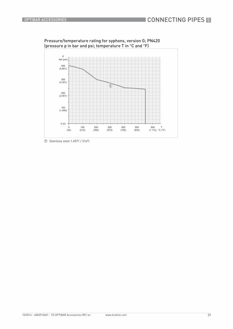
Pressure/temperature rating for syphons, version G; PN420(pressure p in bar and psi; temperature T in °C and °F)
1 Stainless steel 1.4571 / 316Ti

5 CONNECTING PIPES
38
OPTIBAR ACCESSORIES
www.krohne.com 10/2014 - 4003910401 - TD OPTIBAR Accessories R01 en
5.1.1 Straight and curved connecting pipes
Dimensions [mm / inch]
Version A: straight Version B: curved
Version a b
A 100 / 3.94 -
B 100 / 3.94 100 / 3.94
Version Connections Comments
Input, process Output, transmitter
A Ø 20 x 2.6 mm / 0.79 x 0.1", straight
G1/2 swivel female WS 27
B Ø 20 x 2.6 mm / 0.79 x 0.1", 90° curved
Version Order code
A VGKW4 A...
B VGKW4 B...

CONNECTING PIPES 5
39
OPTIBAR ACCESSORIES
www.krohne.com10/2014 - 4003910401 - TD OPTIBAR Accessories R01 en
5.1.2 Syphons in U shape
Dimensions [mm / inch]
Version C1 to C4 Version D
Version a b c
C1 180 / 7.09 155 / 6.10 200 / 7.87
C2 145 / 5.71
C3 180 / 7.09
C4 145 / 5.71
D 253 / 9.96 - -
Version Connections Design
Input, process, d1 Output, transmitter, d2
C1 G1/2 male G1/2 adjusting nut Design A, similar to DIN 16282
C2 Weld connectionØ 20 x 2.6 mm / 0.79 x 0.1"
G1/2 adjusting nut Design B, similar to DIN 16282
C3 1/2 NPT male 1/2 NPT female -
C4 Weld connectionØ 20 x 2.6 mm / 0.79 x 0.1"
1/2 NPT female -
D G1/2 male G1/2 female Standard without offset
Version Order code
C1 VGKW4 Cx23 ...
C2 VGKW4 CxT3 ...
C3 VGKW4 Cx10 ...
C4 VGKW4 CxT0 ...
D VGKW4 Dx23 ...

5 CONNECTING PIPES
40
OPTIBAR ACCESSORIES
www.krohne.com 10/2014 - 4003910401 - TD OPTIBAR Accessories R01 en
5.1.3 Syphons in circular shape
Dimensions [mm / inch]
Version E1 to E4 Version F
Version a c
E1 145 / 5.71 225 / 8.86
E2 110 / 4.33 240 / 9.45
E3 145 / 5.71 275 / 10.83
E4 110 / 4.33 240 / 9.45
F 115 / 4.53 230 / 9.06
Version Connections Design
Input, process, d1 Output, transmitter, d2
E1 G1/2 male G1/2 adjusting nut Design C, similar to DIN 16282
E2 Weld connectionØ 20 x 2.6 mm / 0.79 x 0.1"
G1/2 adjusting nut Design D, similar to DIN 16282
E3 1/2 NPT male 1/2 NPT female -
E4 Weld connectionØ 20 x 2.6 mm / 0.79 x 0.1"
1/2 NPT female -
F G1/2 male G1/2 male Standard
Version Order code
E1 VGKW4 Ex23 ...
E2 VGKW4 ExT3 ...
E3 VGKW4 Ex10 ...
E4 VGKW4 ExT0 ...
F VGKW4 Fx22 ...

CONNECTING PIPES 5
41
OPTIBAR ACCESSORIES
www.krohne.com10/2014 - 4003910401 - TD OPTIBAR Accessories R01 en
5.1.4 Syphons
Compact syphon with integrated damping function
Dimensions [mm / inch]
Version G1: with 1/2 NPT female Version G2: with G1/2 swivel female and damping function
Sectional view of version G2: with G1/2 swivel female and damping function
Version G1 Version G2
Version a b
G1 110 / 4.33 WS 27
G2 120 / 4.72
Version Connections
Input, process Output, transmitter
G1 1/2 NPT male 1/2 NPT female
G2 G1/2 male G1/2 swivel female
Version Order code
G1 VGKW4 G410 ...
G2 VGKW4 G423 ...
5 CONNECTING PIPES
42
OPTIBAR ACCESSORIES
www.krohne.com 10/2014 - 4003910401 - TD OPTIBAR Accessories R01 en
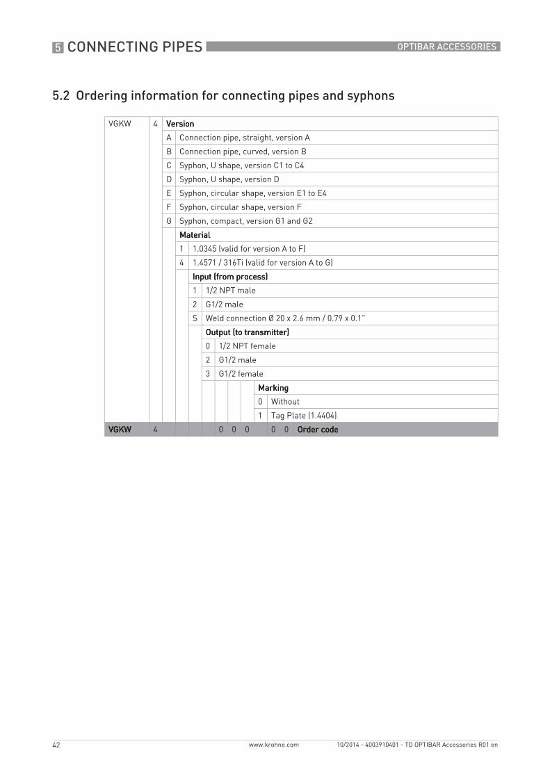
5.2 Ordering information for connecting pipes and syphons
VGKW 4 VersionVersionVersionVersion
A Connection pipe, straight, version A
B Connection pipe, curved, version B
C Syphon, U shape, version C1 to C4
D Syphon, U shape, version D
E Syphon, circular shape, version E1 to E4
F Syphon, circular shape, version F
G Syphon, compact, version G1 and G2
MaterialMaterialMaterialMaterial
1 1.0345 (valid for version A to F)
4 1.4571 / 316Ti (valid for version A to G)
Input (from process)Input (from process)Input (from process)Input (from process)
1 1/2 NPT male
2 G1/2 male
S Weld connection Ø 20 x 2.6 mm / 0.79 x 0.1"
Output (to transmitter)Output (to transmitter)Output (to transmitter)Output (to transmitter)
0 1/2 NPT female
2 G1/2 male
3 G1/2 female
MarkingMarkingMarkingMarking
0 Without
1 Tag Plate (1.4404)
VGKWVGKWVGKWVGKW 4 0 0 0 0 0 Order codeOrder codeOrder codeOrder code

GENERAL ACCESSORIES 6
43
OPTIBAR ACCESSORIES
www.krohne.com10/2014 - 4003910401 - TD OPTIBAR Accessories R01 en
6.1 Fittings – female and male
Fittings Sealing o-ring acc. to EN 837-1
Blind plug Oval flange adapter Gauge snubber
Version 1: to be welded in Version 2: male/female
Version 3: double male
Version 4: double female
Version Connections Dimensions [mm / inch] Material
Input, process Output, transmitter
a b c d
1a Ø 14.9 x 4.5 mm / 0.59 x 0.18"
G1/2 male 40 / 1.57
Ø 14.9 / 0.59
5 / 0.2 WS 27 1.11411.4571 / 316Ti
1b G1/2 male LH (left-hand thread)
1c 1/2 NPT male
1d 1/2 NPT female
2a G1/2 male 1/2 NPT female 45 / 1.77
- - 1.4404 / 316L
2b 1/2 NPT male G1/2 female 50 / 1.97
- -
3a G1/2 male G1/2 male 50 / 1.97
- - 1.4404 / 316L
3b 1/2 NPT male 1/2 NPT male
3c G1/2 male 1/2 NPT male
4 G1/2 female G1/2 female LH (left-hand thread)
36 / 1.41
- - 1.4571 / 316Ti

6 GENERAL ACCESSORIES
44
OPTIBAR ACCESSORIES
www.krohne.com 10/2014 - 4003910401 - TD OPTIBAR Accessories R01 en
6.2 Ordering information for fittings
Version Order code
1a VGKW4 1xR2
1b VGKW4 1xR5
1c VGKW4 1xR1
1d VGKW4 1xR0
2a VGKW4 2320
2b VGKW4 2313
3a VGKW4 3322
3b VGKW4 3311
3c VGKW4 3321
4 VGKW4 4x36
VGKW 4 VersionVersionVersionVersion
1 Fittings with weld ends
2 Fittings with male/female
3 Fittings with double male
4 Fittings with double female
MaterialMaterialMaterialMaterial
3 1.4404 / 316L (valid for version 2 and 3)
4 1.4571 / 316Ti (valid for version 1 and 4)
5 1.1141 (valid for version 1)
Input (from process)Input (from process)Input (from process)Input (from process)
1 1/2 NPT male (valid for version 2 and 3)
2 G1/2 male (valid for version 2 and 3)
3 G1/2 female (valid for version 4)
P Weld connection Ø 14.9 x 4.5 mm / 0.59 x 0.18" (valid for version 1)
Output (to transmitter)Output (to transmitter)Output (to transmitter)Output (to transmitter)
0 1/2 NPT female (valid for version 1 and 2)
1 1/2 NPT male (valid for version 1 and 3)
2 G1/2 male (valid for version 1 and 3)
3 G1/2 female (valid for version 2)
5 G1/2 male LH – left-hand thread (valid for version 1)
6 G1/2 female LH – left-hand thread (valid for version 4)
VGKWVGKWVGKWVGKW 4 0 Order codeOrder codeOrder codeOrder code

GENERAL ACCESSORIES 6
45
OPTIBAR ACCESSORIES
www.krohne.com10/2014 - 4003910401 - TD OPTIBAR Accessories R01 en
6.3 Sealing o-ring acc. to EN 837-1
Flat seals made of different materials
Ordering information
6.4 Blind plug
Ordering information
Sealing o-ring acc. to EN 837-1
Sealing material for thread D d b Item number
[mm / inch]
Aluminium G1/2 17.5 / 0.69 6.2 / 0.24 2 / 0.08 XGKW5 07301
Copper XGKW5 07302
Soft iron XGKW5 07303
Steel 1.4571 XGKW5 07304
PTFE XGKW5 07305
Blind plug Blind plug with valve
Designation Thread Material Item number
Blind plug 1/4 NPT 1.4404 / 316L XGKW5 14002
1/2 NPT XGKW5 14001
Blind plug with valve 1/4 NPT XGKW5 14004
1/2 NPT XGKW5 14003

6 GENERAL ACCESSORIES
46
OPTIBAR ACCESSORIES
www.krohne.com 10/2014 - 4003910401 - TD OPTIBAR Accessories R01 en
6.5 Oval flange adapter
Ordering information
Oval flange adapter acc. to IEC 61518 A
Connections Dimension d[mm / inch]
Material
Input, process Output, transmitter
1/2 NPT female IEC 61518 A 11.8 + 0.2 / 0.46 + 0.008 1.4404 / 316L
Oval flange adapter Item number
Oval flange adapter acc. to IEC 61518 A with 1/2 NPT female XGKW5 13901
Accessory sets for mounting the oval flange to manifold/transmitter acc. to IEC 61518 A
Item number
1 – 2 x hexagonal head screws 7/16-20 UNF made of steel, 1 x PTFE sealing o-ring
XGKW5 13801
2 – 2 x hexagonal head screws 7/16-20 UNF made of stainless steel, 1 x PTFE sealing o-ring
XGKW5 13802
3 – 2 x hexagonal head screws 7/16-20 UNF made of steel, 1 x graphite sealing o-ring
XGKW5 13803
4 – 2 x hexagonal head screws 7/16-20 UNF made of stainless steel, 1 x graphite sealing o-ring
XGKW5 13804

GENERAL ACCESSORIES 6
47
OPTIBAR ACCESSORIES
www.krohne.com10/2014 - 4003910401 - TD OPTIBAR Accessories R01 en
6.6 Gauge snubber
Gauge snubbers are mounted to protect the measuring device. They have a damping effect and reduce the influence of pressure surges.
Ordering information
Gauge snubber Gauge snubber sectional view
Version Connections Dimension a[mm / inch]
Material
Input, process Output, transmitter
1 1/2 NPT male 1/2 NPT female 61 / 2.4 1.4571 / 316Ti
2 G1/2 male G1/2 female
Gauge snubber Item number
Version 1 with 1/2 NPT threads XGKW5 13201
Version 2 with G1/2 threads XGKW5 13202

7 APPENDIX
48
OPTIBAR ACCESSORIES
www.krohne.com 10/2014 - 4003910401 - TD OPTIBAR Accessories R01 en
7.1 Typical measurement setups (hook-ups)
7.1.1 Pressure measurement – Direct mounting – Gaseous
PN400 – with shut-off valve acc. to DIN 16250
Position Pieces Designation
1 1 Discharge nozzle
2 1 Adjusting nut
3 2 Sealing washer acc. to EN 837-1
4 1 Manometer valve DIN 16270 design A without test connection
or
Manometer valve DIN 16270 design A with test connection
5 1 Measuring device

APPENDIX 7
49
OPTIBAR ACCESSORIES
www.krohne.com10/2014 - 4003910401 - TD OPTIBAR Accessories R01 en
PN420 – with barstock valve
Position Pieces Designation
1 1 Discharge nozzle
2 1 PN420 block & bleed valve, 1/2 NPT male/female
3 1 Measuring device

7 APPENDIX
50
OPTIBAR ACCESSORIES
www.krohne.com 10/2014 - 4003910401 - TD OPTIBAR Accessories R01 en
7.1.2 Pressure measurement – Direct mounting – Gaseous/liquid
PN250 – with shut-off valve acc. to DIN 16272
Position Pieces Designation
1 1 Pipe elbow
2 2 Sealing washer acc. to EN 837-1
3 1 Manometer valve DIN 16272 design A with test connection, G1/2 male/adjusting nut
4 1 Measuring device

APPENDIX 7
51
OPTIBAR ACCESSORIES
www.krohne.com10/2014 - 4003910401 - TD OPTIBAR Accessories R01 en
7.1.3 Pressure measurement – Direct mounting – Liquid/vaporous
PN250 – with shut-off valve acc. to DIN 16270
Position Pieces Designation
1 1 Connection pipe
2 2 Sealing washer acc. to EN 837-1
3 1 Manometer valve DIN 16270 design A without test connection, G1/2 male/adjusting nut
or
Manometer valve DIN 16270 design A with test connection, G1/2 male/adjusting nut
4 1 Measuring device

7 APPENDIX
52
OPTIBAR ACCESSORIES
www.krohne.com 10/2014 - 4003910401 - TD OPTIBAR Accessories R01 en
7.1.4 Pressure measurement – Direct mounting – Vaporous
PN100 – with shut-off valve acc. to DIN 16272
Position Pieces Designation
1 1 Syphon acc. to DIN 16282
2 2 Sealing washer acc. to EN 837-1
3 1 Manometer valve DIN 16272 design A with test connection, G1/2 male/adjusting nut
4 1 Measuring device

APPENDIX 7
53
OPTIBAR ACCESSORIES
www.krohne.com10/2014 - 4003910401 - TD OPTIBAR Accessories R01 en
PN400 – with primary shut-off and shut-off valve acc. to DIN 16272
Position Pieces Designation
1 1 Discharge nozzle Ø 21.3 x 3.6 mm / 0.84 x 0.14"
2 1 Primary shut-off valve Ø 21.3 x 3.6 mm / 0.84 x 0.14"
3 1 Syphon acc. to DIN 16282
4 2 Sealing washer acc. to EN 837-1
5 1 Manometer valve DIN 16272 design A with test connection, G1/2 male/swivel female
6 1 Measuring device

7 APPENDIX
54
OPTIBAR ACCESSORIES
www.krohne.com 10/2014 - 4003910401 - TD OPTIBAR Accessories R01 en
7.1.5 Differential pressure measurement – Direct mounting – Gaseous
PN420 – with 3-valve manifold
Position Pieces Designation
1 1 Discharge nozzle Ø 21.3 x 3.6 mm / 0.84 x 0.14"
2 1 Double nipple
3 1 Oval flange adapter
4 1 Accessory set consisting of screws and gaskets
5 1 3-valve manifold PN420; inlet: DIN 19213 A with 7/16-20 UNF thread; testing/venting: 1/4-18 NPT female
or
3-valve manifold PN420; inlet: DIN 19213 A with 7/16-20 UNF thread; without test connection
6 1 Accessory set consisting of screws and gaskets
7 1 Measuring device
APPENDIX 7
55
OPTIBAR ACCESSORIES
www.krohne.com10/2014 - 4003910401 - TD OPTIBAR Accessories R01 en
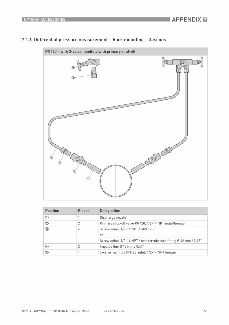
7.1.6 Differential pressure measurement – Rack mounting – Gaseous
PN420 – with 3-valve manifold with primary shut-off
Position Pieces Designation
1 1 Discharge nozzle
2 2 Primary shut-off valve PN420, 1/2-14 NPT male/female
3 4 Screw union, 1/2-14 NPT / SRV 12S
or
Screw union, 1/2-14 NPT / twin ferrule tube fitting Ø 12 mm / 0.47"
4 2 Impulse line Ø 12 mm / 0.47"
5 1 3-valve manifold PN420; inlet: 1/2-14 NPT female

7 APPENDIX
56
OPTIBAR ACCESSORIES
www.krohne.com 10/2014 - 4003910401 - TD OPTIBAR Accessories R01 en
7.1.7 Differential pressure measurement – Rack mounting – Liquid
PN400 – with 5-valve manifold with primary shut-off
Position Pieces Designation
1 1 Discharge nozzle; outlet: weld nozzle Ø 24 x 7.1 mm / 0.94 x 0.28"
2 2 Primary shut-off valve PN400, Ø 24 x 7.1 mm / 0.94 x 0.28" / SRV 12S
3 2 Impulse line Ø 12 mm / 0.47"
4 1 5-valve manifold PN400; inlet: SRV 12S
5 1 Accessory set consisting of screws, U washers and gaskets
6 2 Blow-off line
7 1 Measuring device

APPENDIX 7
57
OPTIBAR ACCESSORIES
www.krohne.com10/2014 - 4003910401 - TD OPTIBAR Accessories R01 en
7.1.8 Differential pressure measurement – Rack mounting – Vaporous
PN400 – with 5-valve HT manifold with primary shut-off
Position Pieces Designation
1 1 Discharge nozzle, Ø 24 x 7.1 mm / 0.94 x 0.28"
2 2 Combination condensate pot/shut-off valve Ø 24 x 7.1 mm / 0.94 x 0.28" / Ø 14 x 2.5 mm / 0.55 x 0.1"
3 2 Impulse line Ø 14 mm / 0.55"
4 1 Manifold combination PN400 Ø 14 x 2.5 mm / 0.55 x 0.1" / SRV 14S
or
Manifold combination PN400 with test connection M20 x 1.5,Ø 14 x 2.5 mm / 0.55 x 0.1" / SRV 14S
5 1 Accessory set consisting of screws, U washers and gaskets
6 2 Blow-off line

7 APPENDIX
58
OPTIBAR ACCESSORIES
www.krohne.com 10/2014 - 4003910401 - TD OPTIBAR Accessories R01 en
7.2 Material designations
Overview of materials used and their application range
Valv
es
Man
ifold
s
Flan
ge a
dapt
er
Con
dens
ate
pots
Con
nect
ing
pipe
s
Syph
ons
Syph
ons,
com
pact
Fitt
ings
Gau
ge s
nubb
er
Oth
er a
cces
sori
es
Material M. no. Short designation
ASTM
Heat-resistant, unalloyed steel
1.0460 P250GH - X X
1.0345 P235GH - X X
1.1141 C15E - X
Austenitic, stainless steel
1.4571 X6CrNiMoTi17-12-2
316Ti X X X X X X X
1.4404 X2CrNiMo17-12-2
316L X X X X
Heat-resistant steel 1.5415 16Mo3 - X
1.7335 13CrMo4-5 F12 X
1.7383 10CrMo9-10 F22 X

NOTES 8
59
OPTIBAR ACCESSORIES
www.krohne.com10/2014 - 4003910401 - TD OPTIBAR Accessories R01 en

KROHNE product overview
• Electromagnetic flowmeters
• Variable area flowmeters
• Ultrasonic flowmeters
• Mass flowmeters
• Vortex flowmeters
• Flow controllers
• Level meters
• Temperature assemblies
• Pressure transmitters
• Analysis products
• Products and systems for the oil & gas industry
• Measuring systems for the marine industry
Head Office KROHNE Messtechnik GmbHLudwig-Krohne-Str. 547058 Duisburg (Germany)Tel.:+49 203 301 0Fax:+49 203 301 103 89 [email protected]
© K
RO
HN
E 10
/201
4 -
4003
9104
01 -
TD
OP
TIB
AR
Acc
esso
ries
R01
en
- Su
bjec
t to
chan
ge w
ithou
t not
ice.
The current list of all KROHNE contacts and addresses can be found at:www.krohne.com


