
1Department Of Occupational Safety and Health
Guidelines On Occupational Safety and Healthfor design, Inspection, Testing and examination of local exhoust ventilation system
Department Of Occupational Safety and Health (DOSH)
Ministry of Human Resources
Level 2,3 & 4, Block D3, Complex D,
Federal Government Administrative Centre
62530 Putrajaya.
on Occupational Safety and Health
for Design, Inspection, Testing and Examination
of Local Exhaust Ventilation System
Department Of Occupat ional Safety and HealthMinistry of Human Resources
Malays ia2008
G U I D E L I N E S
JKKP DP 127/37914-46ISBN 978-983-2014-60-7

2 Department Of Occupational Safety and Health
Guidelines On Occupational Safety and Healthfor design, Inspection, Testing and examination of local exhoust ventilation system

3Department Of Occupational Safety and Health
Guidelines On Occupational Safety and Healthfor design, Inspection, Testing and examination of local exhoust ventilation system

4 Department Of Occupational Safety and Health
Guidelines On Occupational Safety and Healthfor design, Inspection, Testing and examination of local exhoust ventilation system
Foreword
Local exhaust ventilation system is one type of engineering control
equipment that preferred and commonly used in workplace to control
exposure to chemicals hazardous to health. Occupational Safety and Health
(Use and Standards Exposure of Chemicals Hazardous to Health) Regulations
2000 have specified requirements in term of design, commissioning, inspection
and testing of local exhaust ventilation system. The effectiveness and efficiency
of the local exhaust ventilation system depend on the design, usage and
maintenance of the system.
This guideline highlights the design factors that need to be considered
during selection or testing as to ensure that local exhaust ventilation system
will work efficiently and effectively. The guideline also discuss the required
inspection, testing and examination to be carry out in order to ensure proper
commissioning and maintenance of the system.
For further detail information on design and maintenance of the ventilation
system, employers are advised to refer to other references such as the ‘’Industrial
Ventilation - A Manual of Recommended Practice” edited by the American
Conference of Governmental Industrial Hygienists.
The guideline will be reviewed from time to time. If there is any comment
for improvement of the guideline, please do not hesitate to contact the
department.
I would like to thank and acknowledge those who have assist in the development
of the guideline.
DIRECTOR GENERAL
DEPARTMENT OF OCCUPATIONAL SAFETY AND HEALTH
MINISTRY OF HUMAN RESOURCES
2008

5Department Of Occupational Safety and Health
Guidelines On Occupational Safety and Healthfor design, Inspection, Testing and examination of local exhoust ventilation system
Foreword
Definitions
1. Description of local Exhaust Ventilation System and Design Parameter
1.1 Introduction
1.2 Component Of Local Exhaust Ventilation System
1.2.1 Hood
1.2.2 Ducting System
1.2.3 Air Cleaner
1.2.4 Fan
2. legal Provision
3. approved Standard For Design of local Exhaust Ventilation System
4. Inspection, Testing and Examination of local Exhaust
Ventilation System
4.1 Inspection Of Local Exhaust Ventilation System
4.2 Testing And Examination Of Local Exhaust Ventilation System
5. assessment of The Efficiency of local Exhaust Ventilation System
6. Maintenance
7. Record Keeping
8. conclusion
9. Reference
Appendix A: Detail Inspection, Testing and Examination of local
Exhaust Ventilation Procedure
Appendix B: Measurement of Velocity Pressure
Appendix C: Method of Measurement
Appendix D: list of Standard For Designing of local Exhaust
Ventilation System
Table of contents
Page
iii
1
5
6
9
10
12
13
14
15
18
19
20
41
45
46

6 Department Of Occupational Safety and Health
Guidelines On Occupational Safety and Healthfor design, Inspection, Testing and examination of local exhoust ventilation system
absolute Humidity is the weight of water vapor per unit volume, pounds per
cubic foot or grams per cubic centimeter.
aerosol is an assemblage of small particles, solid or liquid, suspended in air. The
diameter of the particles may vary from 100 microns down to 0.01 micron or less,
e.g., dust, mist, smoke.
air cleaner is a device designed for the purpose of removing atmospheric
airborne impurities such as dusts, gases, vapors, fume and smokes. (Air cleaners
include air washers, air filters, electrostatic precipitators and charcoal filters).
air Filter is an Air cleaner to remove light particulate loadings from normal
atmospheric air before introduction into the building. Usual range: Loadings
up to 3 grains per thousand cubic feet (0.003 grains per cubic foot). Note:
Atmospheric air in heavy industrial areas and in plant air in many industries
has higher loadings than this and dust collectors are then indicated for proper
air cleaning.
air, Standard mean dry air at 70 oF and 229.92 in (Hg) barometer. This is
substantially equivalent to 0.075 Ib/cu ft. Specific heat of dry air - 0.24 BTU/lb/F.
atmospheric Pressure is the pressure due to the weight of the atmosphere.
It is the pressure indicated by a barometer. Standard Atmospheric Pressure of
Standard Atmosphere is the pressure of 29.92 inches of mercury.
Blast Gate is a sliding damper or flap commonly for isolating hood when not
in use.
Definitions

7Department Of Occupational Safety and Health
Guidelines On Occupational Safety and Healthfor design, Inspection, Testing and examination of local exhoust ventilation system
Definitions
Blow (throw) in air distribution, mean the distance an air stream travels from
an outlet to a position at which air motion along the axis reduces to a velocity
of 50 fpm. For unit heaters, the distance an air stream travels from a heater
without a perceptible rise due to temperature difference and loss of velocity.
capture Velocity is the air velocity at any point in front of the hood or at the
hood opening necessary to overcome opposing air currents and to capture the
contaminated air at that point by causing it to flow into the hood.
coefficient of Entry is the actual rate of flow caused by a given hood static
pressure compared to the theoretical flow which would result if the static
pressure could be converted to velocity pressure with 100% efficiency. It is the
ratio of actual to theoretical flow.
Density is the ratio of the mass of a specimen of a substance to the volume of
the specimen. The mass of a unit volume of a substance. When weight can be
used without confusion, as synonymous with mass, density is the weight of a
unit volume of a substance.
Density Factor is the ratio of actual air density to density of standard air. The
product of the density factor and the density of standard air (0.075 lb/cu ft) will
give the actual air density in lbs per cu Ft. d x 0.075 = actual density of air, lbs
per cu ft.
Dust is small solid particles created by the breaking up of larger particles by
processes such as crushing, grinding, drilling, explosions, etc. Dust particles
already in existence in a mixture of materials may escape into the air through
such operations as shoveling, conveying, screening, sweeping, etc.
Dust collector is an Air cleaner to remove heavy particulate loadings from
exhaust systems before discharge to outdoors. Usual range: Loadings 0.003
grains per cubic foot and higher.
Entry loss is loss in pressure caused by air flowing into a duct or hood.
(Inches H20).

8 Department Of Occupational Safety and Health
Guidelines On Occupational Safety and Healthfor design, Inspection, Testing and examination of local exhoust ventilation system
Fumes are small solid particles formed by the condensation of vapors of solid
materials.
Gases are formless fluids which tend to occupy an entire space uniformly at
ordinary temperatures and pressures.
Hood is shaped inlet designed to capture contaminated air and conduct it into
the exhaust duct system.
Manometer is an instrument for measuring pressure essentially a U tube partially
filled with a liquid, usually water, mercury or a light oil, so constructed that the,
amount of displacement of the liquid indicates the pressure being exerted on
the instrument.
Mists are small droplets of materials that are ordinarily liquid at normal
temperature and pressure.
Plenum is a pressure equalizing chamber.
Relative Humidity The ratio of the actual partial pressure of the water vapor in a
space to the saturation pressure of pure water at the same temperature.
Slot Velocity is linear flow rate of contaminated air through slot, fpm or m/s.
Smoke is an air suspension (aerosol) of particles, usually but not necessarily
solid, often originating in a solid nucleus, form combustion or sublimation.
Specific Gravity is the ratio of the mass of a unit volume of a substance to the
mass of the same volume of a standard substance at a standard temperature.
Water at 39.2 F is the standard substance usually referred to. For gases, dry air, at
the same temperature and pressure as the gas, is often taken as the stand and
substance.
Static pressure is the potential pressure exerted in all directions by a fluid at
rest. For a fluid in motion it is measured in a direction normal, to the direction

9Department Of Occupational Safety and Health
Guidelines On Occupational Safety and Healthfor design, Inspection, Testing and examination of local exhoust ventilation system
of flow. Usually expressed in inches water gauge when dealing with air. (The
tendency to either burst or collapses the pipe.)
Temperature, Wet Bulb Thermodynamic wetbulb temperature is the
temperature at which liquid or solid water, by evaporating into air, can bring the
air to saturation adiabatically at the same temperature. Wetbulb temperature
(without qualification) is the temperature indicated by a wet bulb psychrometer
constructed and used according to specifications.
Threshold limit Values (TlV): The values for air borne toxic materials which
are to be used as guides in the control of health hazards and represent time
weighted concentrations to which nearly all workers may be exposed 8 hours
per day over extended periods of time without adverse effects.
Total Pressure is the algebraic sum of the velocity pressure and the static
pressure (with due regard to sign).
Transport (conveying) Velocity is velocity that has to be sufficient to overcome
energy losses along the duct to avoid clogging.
Vapor Pressure is the pressure exerted by a vapor. If a vapor is kept in
confinement over its liquid so that the vapor ran accumulate above the liquid,
the temperature being held constant, the vapor pressure approaches a fixed
limit called the maximum or saturated, vapor pressure, dependent only on
the temperature and the liquid. The term vapor pressure is sometimes used as
synonymous with saturated vapor pressure.
Velocity Pressure is the kinetic pressure in the direction of flow necessary to
cause a fluid at rest to f low at a given velocity. Usually expressed in inches water
gauge.
Vapor The gaseous form of substances which are normally in the solid or liquid
state arid which can be changed to these states either by increasing the pressure
or decreasing the temperature. Vapors diffuse.

10 Department Of Occupational Safety and Health
Guidelines On Occupational Safety and Healthfor design, Inspection, Testing and examination of local exhoust ventilation system
1. DEScRIPTIoN oF local EXHaUST VENTIlaTIoN SYSTEM aND DESIGN PaRaMETER
1.1 Introduction
Local exhaust ventilation system is the most common type of engineering
control equipment used to control exposure of employees to chemicals
hazardous to health. Local exhaust ventilation system operate on the principle
of capturing a contaminant at or near its source before they are dispersed into
the workroom environment. Contaminants can be in the form of dust, smoke,
mist, aerosol, vapour and gas.
1.2 component of local Exhaust Ventilation System
Local exhaust ventilation system are comprised of up to four basic elements:
hood, duct system, air cleaner and fan.
Figure 1: Components of Local Exhaust Ventilation
DUCTINGAIR
CLEANER
STACK
FAN
HOOD
11Department Of Occupational Safety and Health
Guidelines On Occupational Safety and Healthfor design, Inspection, Testing and examination of local exhoust ventilation system
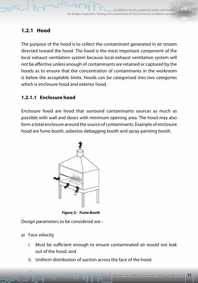
1.2.1 Hood
The purpose of the hood is to collect the contaminant generated in air stream
directed toward the hood. The hood is the most important component of the
local exhaust ventilation system because local exhaust ventilation system will
not be effective unless enough of contaminants are retained or captured by the
hoods as to ensure that the concentration of contaminants in the workroom
is below the acceptable limits. Hoods can be categorised into two categories
which is enclosure hood and exterior hood.
1.2.1.1 Enclosure hood
Enclosure hood are hood that surround contaminants sources as much as
possible with wall and doors with minimum opening area. The hood may also
form a total enclosure around the source of contaminants. Example of enclosure
hood are fume booth, asbestos debagging booth and spray painting booth.
Design parameters to be considered are -
a) Face velocity
i. Must be sufficient enough to ensure contaminated air would not leak
out of the hood; and
ii. Uniform distribution of suction across the face of the hood.
Figure 2: Fume Booth

12 Department Of Occupational Safety and Health
Guidelines On Occupational Safety and Healthfor design, Inspection, Testing and examination of local exhoust ventilation system
b) Rate of flow
i. Rate of suction must be more than rate of contaminated air produce;
ii. Rate of flow must be equally distributed as to ensure there is no null
point. This can be achieved by installing guide such as baffles or plenum;
and
iii. Coefficient of entry will determine the efficiency of the hood.
c) Size of enclosure
i. Must be large enough to accommodate contaminated air.
1.2.1.2 Exterior hood
Exterior hood are hood that “reach out” to capture contaminants in the work
room and located adjacent to source of contaminant and not enclosing it.
Example of exterior hood are side hood, slot hood, downdraft hood, push - pull
system hood, low volume and high velocity hood and canopy hood.
CanopySlot Hood
Side HoodDowndraft
Figure 3: Example of Exterior Hood
Low Volume and High Velocity Hood

13Department Of Occupational Safety and Health
Guidelines On Occupational Safety and Healthfor design, Inspection, Testing and examination of local exhoust ventilation system
Design parameters to be considered are:
a) Capture velocity
i. Must ensure sufficient capture velocity that will capture all contaminated
air and flow into the hood; and
ii. Must be able to overcome cross draft.
b) Hood flow rate
i. The distance between the hood and source of contaminant will
determine the efficiency and effectiveness of the suction;
ii. Type of hood will affect the hood flow rate; and
iii. Coefficient of entry will determine the efficiency of the hood.
c) Effect of flanges and baffles
i. A flange can provide barrier to unwanted air flow from behind the hood;
and
ii. Flange can reduce suction rate required by 25%.
d) Air distribution
i. Must ensure suction air distribute uniformly across the opening of the
hood; and
ii. Slot and plenum can distribute suction air uniformly.
e) Shape and size of the hood
i. The process and how the worker work relative to the hood must be
considered in design of the hood.
f) Worker position effect
i. Worker position and direction of flow of air in a room need to be consider
when positioning the hood; and
ii. Preferable airflow is from the side of the worker.

14 Department Of Occupational Safety and Health
Guidelines On Occupational Safety and Healthfor design, Inspection, Testing and examination of local exhoust ventilation system
g) Location and position of the hood
i. Must ensure the hood does not interfere with the task that worker has to
carry out;
ii. Must avoid cross draft; and
iii. Ensure no blower or fan does not effect the efficiency of the hood.
1.2.2 Ducting System
A ducting system is a network of ducts that connect the hood and other
components of the local exhaust ventilation system. The ducting system
transport contaminated air to the Air Cleaner. Duct on the fan outlet usually
discharges the air to the atmosphere.
The most important consideration in ducting system design is to reduce losses
of energy that will affect the flow of contaminated air in the duct. Reduction of
flow in the duct will cause dust to settle in the duct and resulting in plugging
problem and this will reduce rate of suction at the hood. Design parameters to
be considered are -
Figure 4: Ducting System

15Department Of Occupational Safety and Health
Guidelines On Occupational Safety and Healthfor design, Inspection, Testing and examination of local exhoust ventilation system
a) Flow in the duct
i. Transport velocity must be sufficient to overcome energy losses along
the duct to avoid clogging.
b) Duct material
i. Must be able to withstand abrasion and corrosive material; and
ii. Corrugated pipe has high friction loss.
c) Shape and size
i. Round duct is prefer than rectangular duct because more energy loss in
rectangular duct.
d) Components of ducting system
i. Such as branch, elbow, enlargement and other component has to be
design properly to avoid energy losses e.g. bend in the system should
has large radii; and
ii. Any local exhaust ventilation system which has more than one hood
will need to be balanced so that each branch will extract just the right
amount of air through the hood. The air flow in each branch will be
determined by the resistance of the hood, the length, diameter and flow
of the branch duct and the flow conditions at the junction with the
main duct.
e) Fitting attach to ducting system
i. Damper cannot be tempered by worker;
ii. Smooth hole to reduce friction loss; and
iii. Internal flanges not to be used.
1.2.3 air cleaner
Air cleaner is a device to remove contaminants that are carried in the
contaminated air from hood which cannot be discharged into the community
environment or to recover materials that have a salvage value. Air cleaner is also

16 Department Of Occupational Safety and Health
Guidelines On Occupational Safety and Healthfor design, Inspection, Testing and examination of local exhoust ventilation system
required to clean exhaust air when the exhaust air is to be re-circulated back to
workplace. Some examples of air cleaner filter bag, cyclone and wet scrubber.
Design parameters to be considered are:
a) Contaminant characteristic
i. Will determine the type of air cleaner to be used; and
ii. To take into consideration that wood dust from most machining
processes or other type of dust that contain explosible fraction.
b) The amount of contaminant extracted
i. Will determine the size of the air cleaner require.
c) Gas stream characteristic
i. The temperature, the amount of water and other characteristic of the
gas stream will determine the type of air cleaner.
Figure 5: Air Cleaner

17Department Of Occupational Safety and Health
Guidelines On Occupational Safety and Healthfor design, Inspection, Testing and examination of local exhoust ventilation system
d) Efficiency of the air cleaner
i. The efficiency of the air cleaner will determine the amount of contaminant
still remain in emission air to the environment.
e) Pressure losses
i. Will determine the amount of energy of auxiliary energy required at the
fan. The designer has to specify pressure limit for clean up or check out
of the air cleaner.
1.2.4 Fan
Fan is the air moving device that provides the energy to draw air and
contaminants into the hood by inducing a negative pressure or suction in the
ducts leading to the hoods. The fan converts electrical power or other form of
energy into negative pressure and increased air velocity.
The fan must overcome all the losses due to friction, hood entry, losses in the
ducting system and losses due to air cleaner while producing the required flow
rate that is enough to extract and transport contaminated air. Design parameters
to be considered are -
a) Required flow rate
i. Based on total flow rate require by the hold system.
Figure 6: Example of fans.

18 Department Of Occupational Safety and Health
Guidelines On Occupational Safety and Healthfor design, Inspection, Testing and examination of local exhoust ventilation system
b) Fan pressure requirement
i. To over come overall resistance of the system; and
ii. Express as fan static pressure or total fan static pressure.
c) Material handled through the fan
i. Will determine the type of fan selected.
d) Location and position
i. The size of the location also will determine the type of fan to be used.
e) Other consideration
i. Expected noise level.
f) Fan curve
i. Three curves that can be used to describe the performance of a fan are
static pressure curve, brake horsepower curve and mechanical efficiency
curve;
ii. Static pressure curve will indicate the quantity of air that the fan will
deliver at a given rotating speed depends on the resistance it is working
against;
iii. Brake Horsepower curve will indicate the amount of electrical power
needed to spin the fan depends on the fan’s output and the system
resistance; and
iv. Mechanical efficiency curve will indicate how much energy the fan uses
at different points on the static pressure curve.
Well designed and good maintenance system is two important factors in
ensuring effectiveness of local exhaust ventilation system.
2. lEGal PRoVISIoN
Occupational Safety and Health (Use and Standard Exposure to Chemicals
Hazardous to Health) Regulations 2000 defined engineering control as any

19Department Of Occupational Safety and Health
Guidelines On Occupational Safety and Healthfor design, Inspection, Testing and examination of local exhoust ventilation system
equipment which is used to control exposure of employees to chemicals
hazardous to health and includes local exhaust ventilation equipment, water
spray or any other airborne chemical removal and containment equipment.
Regulation 17 stipulated that any engineering control equipment has to be
inspected at an interval not longer than one month and has to be examined and
tested by Hygiene Technician at an interval not longer than twelve months.
Regulation 18 stipulated that local exhaust ventilation system has to design
according to approved standard by registered professional engineer. This
regulation also stipulated the responsibility of registered professional engineer
to test the local exhaust ventilation system after construction and installation.
Regulation 19 stipulated the type of records the employer has to keep and
produced for inspection when requested by Director General of Occupational
Safety and Health.
3. aPPRoVED STaNDaRD FoR DESIGN oF local EXHaUST VENTIlaTIoN SYSTEM
There is no specific standard for designing of local exhaust ventilation system.
Industrial ventilation – A Manual of Recommended Practice by ACGIH is the
most common reference book used by designer of local exhaust ventilation
system. So the designer has to submit standard to be used for approval by
Director General of Occupational Safety and Health before can proceed with
the design. Appendix D list out some of the standard that can be used.
4. INSPEcTIoN, TESTING aND EXaMINaTIoN oF local EXHaUST VENTIlaTIoN SYSTEM
Every local exhaust ventilation system should be inspected, tested and examined
at regular interval to ensure the system works properly and efficiently. A new
installed system should be thoroughly tested and examined as to ensure that
the design specifications are met and airflow through each of the hood is
sufficient to extract contaminant effectively away from the workroom.

20 Department Of Occupational Safety and Health
Guidelines On Occupational Safety and Healthfor design, Inspection, Testing and examination of local exhoust ventilation system
4.1 Inspection of local Exhaust Ventilation System
Inspection of local exhaust ventilation system has to be done at least once
a month as required by the regulations or at shorter interval as specified by
the designer. The purpose of inspection is to ensure the system functioning
properly and effectively. The inspection can be done by any person that has
been taught the procedure to carry out the inspection. Inspection of local
exhaust ventilation system consists of -
a) Inspection of physical condition of all component of local exhaust
ventilation system;
b) Observation of how the work carried out in relation to the utilisation of
local exhaust ventilation system;
c) Smoke tube tracer test;
d) Identify any thing that can be obstruction of flow;
e) Observation of condition surrounding and near the hood;
f) Inspection on the air cleaner device; and
g) Maintenance of the fan’s motor.
Testing and examination have to be carried out if there is indication reduction
in flow or every 12 months. Detail on inspection procedure is in appendix A.
4.2 Testing and Examination of local Exhaust Ventilation System
Testing and examination of local exhaust ventilation system has to be carried
out at least every 12 months or at shorter interval as specified by the designer.
The purpose of the testing and examination is to determine the effectiveness
and efficiency of the local exhaust ventilation system and to detect malfunction
of the system. Testing and examination also need to be done during
commissioning of a new installed local exhaust ventilation system as to verify
that the system is working as per design. These data are the baseline data that
will be used for comparison when subsequent testing and examination to be

21Department Of Occupational Safety and Health
Guidelines On Occupational Safety and Healthfor design, Inspection, Testing and examination of local exhoust ventilation system
carried out, in order to determine the effectiveness and efficiency of the system
and to detect any malfunction in the system. Testing and examination of local
exhaust ventilation system consist of -
a) Inspection of local exhaust ventilation system as specified in subsection
4.1;
b) Determination of capture or face velocity;
c) Determination of hood static pressure;
d) Determination of duct static pressure along the ducting system;
e) Determination of hood velocity pressure and transport velocity;
Fig. 7: Anemometer
Figure 8: Measurement of face velocity

22 Department Of Occupational Safety and Health
Guidelines On Occupational Safety and Healthfor design, Inspection, Testing and examination of local exhoust ventilation system
f) Determination of air cleaner’s efficiency; and
g) Determination of fan’s capacity and efficiency.
Detail on inspection, examination and testing procedure is in appendix A.
Figure 10: Measurement of duct velocity and temperature
Figure 9: Method of Measurement Of Velocity Pressure with Pitot Tube

23Department Of Occupational Safety and Health
Guidelines On Occupational Safety and Healthfor design, Inspection, Testing and examination of local exhoust ventilation system
5. aSSESSMENT oF THE EFFIcIENcY oF local EXHaUST VENTIlaTIoN SYSTEM
Assessment of the efficiency can be done by analysing results of inspection,
testing and examination of local exhaust ventilation system mentioned in
section 4.0. Results of physical inspection and observation while the system is
in operation are very important in the assessment of the system. The smoke
tube tests will show how and where contaminants are escaping from the hoods
into the workroom and the effect of cross draft. The design of the hood is very
important because the efficiency of the hood will be affected. Assessment is
carried out by comparing the result of the measurement with baseline data
or standard. The result that is more than + 10 % of the design specification or
below the standard indicate that there is something wrong with the system and
further investigation and analysis need to be carried out to determine the cause
of the problem.
Baseline data can be compared with design specification or standard to ensure
that the system will be effective in the future. Filter for the air cleaner will
increase the resistance if not clean regularly. The fan inlet is important in getting
proper fan performance. Spinning or non-uniform flow pattern will reduce the
fan’s air volume or static pressure output. The result that is more than + 10 %
of the design specification or standard indicate that there is something wrong
with the system and further investigation and analysis need to be carried out to
determine the cause of the problem.
Balance system is very important to ensure all hood will work effectively. The
pressure loss in each duct that meets at same junction must be equal. If one
duct has larger diameter and the other is narrow, then more air will flow through
the wider duct. If both of the same diameters but one is longer then the other,
more air will flow through the shorter duct because the resistance is lower.
The result that is more than + 10 % of the design specification or below the
standard indicate that there is something wrong with the system and further
investigation and analysis need to be carried out to determine the cause of the
problem. Rectification to the system has to be made and retesting has to be
carried out.

24 Department Of Occupational Safety and Health
Guidelines On Occupational Safety and Healthfor design, Inspection, Testing and examination of local exhoust ventilation system
6. MaINTENaNcE
Maintenance is practically an important aspect in ensuring that local exhaust
ventilation system will continuous operating effectively and efficiently as
intended, if not at par with when newly installed. The employer has to plan
periodic maintenance at regular interval to ensure all components of local
exhaust ventilation are in good and operational condition. This will ensure that
the local exhaust ventilation is always operational while any plant or process is
in operation.
The employer also needs to look into the requirement of contingency plan to
overcome power failure or breakdown of the system.
7. REcoRD KEEPING
The employer has to keep record specify below -
a) Design;
b) Construction;
c) Testing, inspection and examination; and
d) Maintenance.
8. coNclUSIoN
Effectiveness and efficiency of the local exhaust ventilation system depend
on design, regular maintenance, proper usage and regular inspection of the
system.
9. REFERENcEa) ACGIH Ventilation Manual edition 23.b) Handbook of Ventilation for Contaminant Control by Henry J. Mc. Dermott.c) Occupational Safety and Health (Use and Standard of Exposure of Chemicals
Hazardous to Health) Regulation 2000.d) Guidelines on inspection, testing and examination of local exhaust
ventilation system by Department of Occupational Safety and Health.e) HSE web site.f) OSHA web site.
g) NIOSH web site.

25Department Of Occupational Safety and Health
Guidelines On Occupational Safety and Healthfor design, Inspection, Testing and examination of local exhoust ventilation system
Appendix A: DETaIl INSPEcTIoN, TESTING aND EXaMINaTIoN oF local EXHaUST VENTIlaTIoN PRocEDURE
1.0 Precaution During Inspection, Testing and Examination
Precautionary measures that should be taken during inspection, testing and
examination local exhaust ventilation system are as follow -
a) Inspection, testing and examination on inside of ducts
Precautionary measure should be taken to prevent chemical poisoning or
exposure to chemical hazards during inspection of inside the duct.
b) Inspection, testing and examination on motors
Precautionary measure should be taken to prevent contacts with dangerous
part of motor that can hurt and injured a person during inspection, testing
and examination.
c) Inspection, testing and examination on passages and scaffolds
Precautionary measure should be taken to prevent slip or fall down during
inspection, testing and examination.
d) Inspection, testing and examination on electrical parts
Precautionary measure should be taken to prevent electrical shock.
2.0 Instruments Use For Inspection
Instruments and tools needed for inspection of a local exhaust ventilation
system are as follow.

26 Department Of Occupational Safety and Health
Guidelines On Occupational Safety and Healthfor design, Inspection, Testing and examination of local exhoust ventilation system
a) Smoke tube use to indicate direction of air flow
b) Manometer use for measuring static pressure
c) Traverse pitot tube use for measuring velocity pressure
connected to manometer
d) Surface thermometer or use for measuring bearing
glass thermometer box surface temperature
e) Test hammer use for sound test of thick wall ducting
f ) Wooden or bamboo bar use for sound test of thin wall ducting
g) Tachometer use for measuring fan speed
h) Anemometer use for measuring air velocity
ToolS INSPEcTIoN

27Department Of Occupational Safety and Health
Guidelines On Occupational Safety and Healthfor design, Inspection, Testing and examination of local exhoust ventilation system
Inspection Item Inspection Procedure Inspection Indicator
1. Physical
appearance
of the hood
2. Obstruction
of flow
Inspect outer and inner
surface of the hood.
a. Observe how the
employee work with
respect to hood.
3.0 Inspection, Examination and Testing Procedure
a) Hood
The following condition
should not occur -
• Abrasion,corrosion
and dents and other
damages which can
affect air flow; and
• Damageofcoating
which can cause
corrosion of the hood.
Rectification has to be
done before inspection
can be proceed
The design -
• shouldbesuitablefor
the process or work;
and
• shouldnothinder
employee from carry
out work

28 Department Of Occupational Safety and Health
Guidelines On Occupational Safety and Healthfor design, Inspection, Testing and examination of local exhoust ventilation system
Inspection Item Inspection Procedure Inspection Indicator
b. Inspect for obstructions
to the opening of the
hood by structure such
as pole, wall that other
that can obstruct the
flow of air.
c. Inspect if any
instrument, tool,
material being
fabricated, raw material,
etc. that is place in such
a way that can obstruct
the flow of air into the
hood.
d. The exhaust system
is in operation. Carry
out smoke tracer test.
The smoke from the
smoke tube will follow
the air current and its
movement will show
how air flow into the
hood. Observe smoke
movement at the test
positions.
The hood opening
should not be blocked
or obstructed by any
structure such as pole,
wall or other which can
obstruct the flow or air
into the hood.
The hood opening
should not be blocked
or obstructed by any
instruments, tools,
materials etc in such a way
that can obstruct the flow
of air into the hood.
The test –
• Showthemovement
and dispersion of air
flow from a source of
contaminant. Smoke
must not flow out of
the hood or lingering
around the hoods
but must be sucked
completely into the
hood;
• Determinethe
approximate capture
distance for hoods;

29Department Of Occupational Safety and Health
Guidelines On Occupational Safety and Healthfor design, Inspection, Testing and examination of local exhoust ventilation system
i. Enclosure Hood
Opening of the hood
is divided into at least
16 equal areas. For
narrow opening, the
area must be divided
into more than 2
equal areas. Dotted
mark is the centre of
equal area and smoke
is blown at the centre
of equal area and
smoke is blown at the
centre of equal area.
• Determinethe
approximate capture
distance for hoods; and
• Determinetheeffect
of cross drafts on hood
performance.
Inspection Item Inspection Procedure Inspection Indicator

30 Department Of Occupational Safety and Health
Guidelines On Occupational Safety and Healthfor design, Inspection, Testing and examination of local exhoust ventilation system
Inspection Item Inspection Indicator
Same procedure for other
types of enclosure hood.
ii. Exterior Hood
Smoke should be blown from
the position of the source of
contaminants The dotted line
shows positions.
Same procedure apply to other
types of exterior hood.
Side Hood
canopy
Downdraft Hood
Inspection Procedure

31Department Of Occupational Safety and Health
Guidelines On Occupational Safety and Healthfor design, Inspection, Testing and examination of local exhoust ventilation system
Observe the performance of
the hood when the process is
in operation. Look at the size,
the positioning and location
of the hood relative to source
of contaminant and the way
the worker work relative to the
hood.
Measure air velocity with an
anemometer.
i. Enclosure Hood
Opening of the hood is
divided into at least 16 equal
areas. For narrow opening,
the area must be divided
into more than 2 equal areas.
Dotted mark is the center of
equal area and measurement
should be done at the center
of equal area.
Same procedure for other types
of enclosure hood
Inspection Item Inspection Procedure Inspection Indicator
Contaminated air
must be sucked
into the hood
completely and
away from the
worker.
Measured air
velocity must be
within 10 percent
of design value or
standard.
3. Direction
and size of
opening
area for
exterior
hoods
4. Velocity

32 Department Of Occupational Safety and Health
Guidelines On Occupational Safety and Healthfor design, Inspection, Testing and examination of local exhoust ventilation system
Inspection Item Inspection Indicator
ii. Exterior Hood
Measurement should be done
from the nip point of the source
of contaminants. The dotted
mark shows the nip point
Check result of environmental
monitoring.
Inspection Procedure
Concentration
of contaminant
must not exceed
Permissible
Exposure Limit
Value stated in
the regulations.
5. Environmental
Monitoring

33Department Of Occupational Safety and Health
Guidelines On Occupational Safety and Healthfor design, Inspection, Testing and examination of local exhoust ventilation system
Inspection Item Inspection IndicatorInspection Procedure
A manometer is used
for hood static pressure
measurement. Tapered
hood-a hole of 1/16 to 1/8 in
diameter is drill on the duct
at about one duct diameter
away from the hood.
Flanged or plain hood- a hole
of 1/16 to 1/8 in. In diameter
is drill on the duct at about
three duct diameter away
from the hood.
The manometer is connected
to the hole with rubber
tubing.
The difference
between the static
pressure reading
and design static
pressure must
not exceed 10
percent.
6. Hood Static
Pressure

34 Department Of Occupational Safety and Health
Guidelines On Occupational Safety and Healthfor design, Inspection, Testing and examination of local exhoust ventilation system
d) Duct
a. The following
condition should
not occur -
• Abrasion,
corrosion and
dents and
other damages
which can
affect air
flow or cause
leakages.
• Damagesof
coating which
can cause
corrosion of
the duct.
• Deformation
which can
cause an
increase of
the air flow
resistance or
piling up of
dust, etc.
b. Rectification
has to be
done before
inspection can
proceed.
Inspection Item Inspection IndicatorInspection Procedure
Inspect the condition of the
outer surface of the duct
system. Start the inspection
from the hood and inspect
all duct connections.
Inspect the main duct and
branch duct.
1. Physical
condition of
duct outer
surface

35Department Of Occupational Safety and Health
Guidelines On Occupational Safety and Healthfor design, Inspection, Testing and examination of local exhoust ventilation system
Inspection Item Inspection IndicatorInspection Procedure
2. Physical
condition
of inner
surface of
the ducts.
a. Inspect the condition of
the inner surface of the
duct system through the
inspection holes. If there
is no inspection holes,
disconnect duct joints
for inspection.
b. When inspection as in (a)
cannot be done, hit the
duct gently and listen
to the sound make by
the duct. This hammer
test should be done at a
position near the elbow
or other position where
dust tend to pile up.
Instrument use foe this
test -
The following
condition should not
occur -
• Abrasion,corrosion
and dents and other
damages which can
affect air flow or
cause leakages.
• Damagesofcoating
which can cause
corrosion of the
duct.
• Pilingupofdust,
etc.
Rectification has to be
done before inspection
can proceed.
No abnormal noise
caused by dust
accumulation, etc,
should be heard.
36 Department Of Occupational Safety and Health
Guidelines On Occupational Safety and Healthfor design, Inspection, Testing and examination of local exhoust ventilation system
Inspection Item Inspection IndicatorInspection Procedure
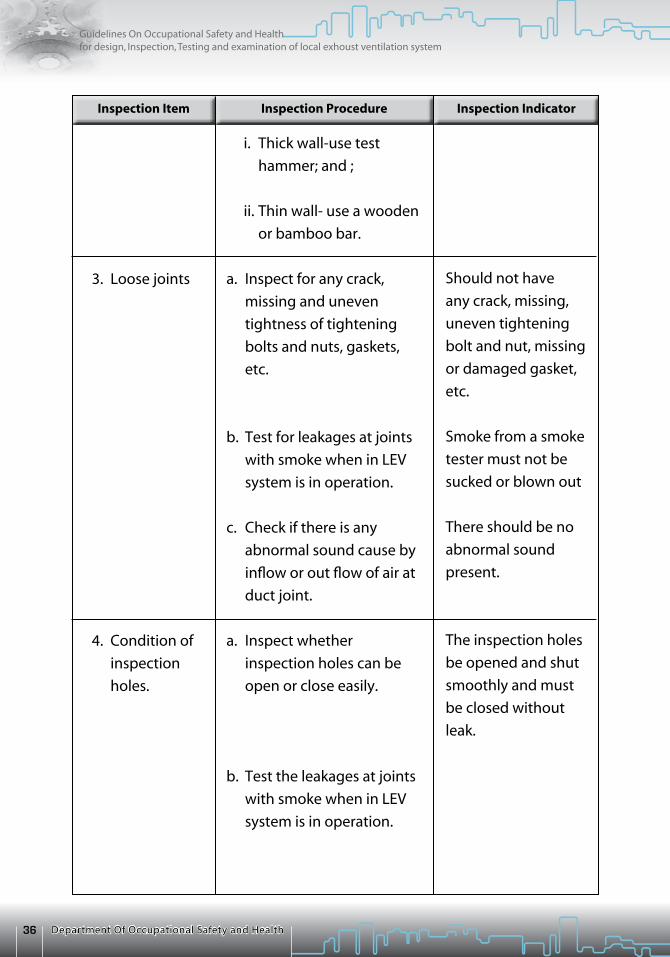
Should not have
any crack, missing,
uneven tightening
bolt and nut, missing
or damaged gasket,
etc.
Smoke from a smoke
tester must not be
sucked or blown out
There should be no
abnormal sound
present.
The inspection holes
be opened and shut
smoothly and must
be closed without
leak.
i. Thick wall-use test
hammer; and ;
ii. Thin wall- use a wooden
or bamboo bar.
a. Inspect for any crack,
missing and uneven
tightness of tightening
bolts and nuts, gaskets,
etc.
b. Test for leakages at joints
with smoke when in LEV
system is in operation.
c. Check if there is any
abnormal sound cause by
inflow or out flow of air at
duct joint.
a. Inspect whether
inspection holes can be
open or close easily.
b. Test the leakages at joints
with smoke when in LEV
system is in operation.
3. Loose joints
4. Condition of
inspection
holes.

37Department Of Occupational Safety and Health
Guidelines On Occupational Safety and Healthfor design, Inspection, Testing and examination of local exhoust ventilation system
Inspection Item Inspection IndicatorInspection Procedure
a. Measure the static
pressure in the duct
with a manometer at
the inspection holes
which are equipped
on the duct before
and after the position
where dust tend to
be piled up such as at
position just before
the duct stands
upward. The holes
should be at least
7.5 duct diameters
down stream from any
disturbance. If this is
not possible then four
holes should be drilled
90o apart around
the duct and static
pressure are measure
at each holes and
averaged
b. Measure the static
pressure in the duct
with a manometer at
measuring holes which
are equipped on the
duct line, e.g. near
joints.
Static pressure in
the duct must be
within the range
of + 10% of
baseline static
pressure (SP + 10%).
5. Static pressure
38 Department Of Occupational Safety and Health
Guidelines On Occupational Safety and Healthfor design, Inspection, Testing and examination of local exhoust ventilation system
Inspection Item Inspection IndicatorInspection Procedure
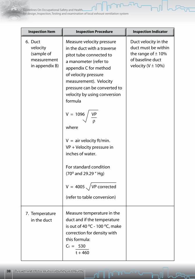
Duct velocity in the duct must be within the range of + 10% of baseline duct velocity (V + 10%)
Measure velocity pressure
in the duct with a traverse
pitot tube connected to
a manometer (refer to
appendix C for method
of velocity pressure
measurement). Velocity
pressure can be converted to
velocity by using conversion
formula
V = 1096 VP
rwhere
V = air velocity ft/min.
VP + Velocity pressure in
inches of water.
For standard condition
(70o and 29.29 “ Hg)
V = 4005 VP corrected
(refer to table conversion)
Measure temperature in the
duct and if the temperature
is out of 40 oC - 100 oC, make
correction for density with
this formula:
Ct = 530
t + 460
6. Duct velocity
(sample of measurement in appendix B)
7. Temperature
in the duct

39Department Of Occupational Safety and Health
Guidelines On Occupational Safety and Healthfor design, Inspection, Testing and examination of local exhoust ventilation system
Inspection Item Inspection IndicatorInspection Procedure
The damper must
be fixed at an
open position at
which the air flow
rate is adjusted to
maintain adequate
performance of
the local exhaust
ventilation system.
The damper must be
manipulated easily
with a weak force.
Smoke must sucked
into the hood when
air flow path is open
and not be sucked
into the hood when
the air flow path is
closed.
The reading must
be within + 10% of
design SP
a. Inspect the opening
degree and fixing
condition of the damper.
b. Smoke from smoke
tube should be sucked
into the hold when the
damper is open and
not when the damper is
closed.
Measure static pressure
at least 7.5 duct diameter
downstream from any
disturbance. If this is not
possible then four holes
should be drilled 90o
apart around the duct and
average static pressure
values.
1. Condition of
damper
2. Static
pressure
c) Damper

40 Department Of Occupational Safety and Health
Guidelines On Occupational Safety and Healthfor design, Inspection, Testing and examination of local exhoust ventilation system
Inspection Item Inspection IndicatorInspection Procedure
a. The following
condition should not
occur -
• Abrasion,corrosion
and dents and other
damages which
can decrease the
performance of the
fan.
• Damagesofcoating
which can cause
corrosion of the fan.
b. Rectification has
to be done before
inspection can
proceed.
The following condition
should not occur -
• Abrasion,corrosion
and dents and other
damages which
can decrease the
performance of the
fan.
• Damageofcoating
which can cause
erosion of the fan.
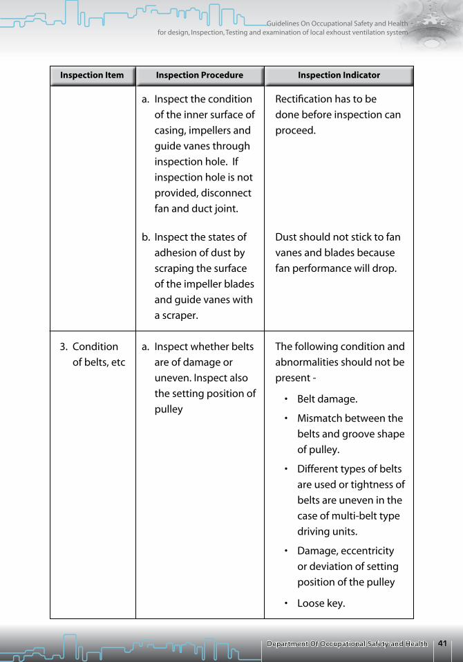
Inspect the condition of
the casing surface.
If the results of the
inspection on suction
and exhaust capacities
as inspection item 4 in
subsection 1 does not
meet the inspection
indicator, inspect the
condition of inner
surface of casing,
impeller and guide vane
in accordance with the
following procedure -
1. Condition of
outer casing
surface
2. Condition of
inner surface
of casings,
impellers and
guide vanes
c) Fan
41Department Of Occupational Safety and Health
Guidelines On Occupational Safety and Healthfor design, Inspection, Testing and examination of local exhoust ventilation system
Inspection Item Inspection IndicatorInspection Procedure
Rectification has to be
done before inspection can
proceed.
Dust should not stick to fan
vanes and blades because
fan performance will drop.
The following condition and
abnormalities should not be
present -
• Beltdamage.
• Mismatchbetweenthe
belts and groove shape
of pulley.
• Differenttypesofbelts
are used or tightness of
belts are uneven in the
case of multi-belt type
driving units.
• Damage,eccentricity
or deviation of setting
position of the pulley
• Loosekey.
a. Inspect the condition
of the inner surface of
casing, impellers and
guide vanes through
inspection hole. If
inspection hole is not
provided, disconnect
fan and duct joint.
b. Inspect the states of
adhesion of dust by
scraping the surface
of the impeller blades
and guide vanes with
a scraper.
a. Inspect whether belts
are of damage or
uneven. Inspect also
the setting position of
pulley
3. Condition
of belts, etc

42 Department Of Occupational Safety and Health
Guidelines On Occupational Safety and Healthfor design, Inspection, Testing and examination of local exhoust ventilation system
Inspection Item Inspection IndicatorInspection Procedure
The following condition
must be satisfied 0.01
L< x < 0.02 L
L and x are as shown in
the figure -
Slippage and vibration
of the belts must not be
present.
Rotating speed of the
fan must not be less than
10 percent of the design
speed.
It must be as specified in
design.
b. Check the sag (x) of
the belts. The belt
is pushed down
word and the sag is
measured.
c. Check slippage and
vibration of the
belts when fan is in
operation.
d. In case the result of
the face or capture
velocity does not
meet the inspection
indicator, measure
the fan speed with a
tachometer.
Examine fan rotating
direction if the face or
capture velocity does
not meet the inspection
indicator.
4. Rotating
direction of
fan
L/2X
BELT
L

43Department Of Occupational Safety and Health
Guidelines On Occupational Safety and Healthfor design, Inspection, Testing and examination of local exhoust ventilation system
Inspection Item Inspection IndicatorInspection Procedure
Abnormal noise must not
be present.
The temperature of the
bearing box surface
should be low that it can
be touch by hand.
The bearing surface
temperature must be
below 70 oF, and the
temperature difference
between the bearing
surface temperature and
surrounding temperature
must be less than 40 oF.
a. Start the fan and
listen if there is any
abnormal noise at the
bearing box.
b. Stop the fan after one
hour operation and
touch the bearing box
with hand.
c. If the result of
inspection procedure
2 does not meet
the inspection
indicator, measure
the bearing box
surface temperature
and the surrounding
temperature. Surface
temperature of
the bearing box is
measured with surface
thermometer or a glass
thermometer which
is attached on the
bearing box surface
with putty.
d. Inspect the amount
of oil and grease in oil
cups and grease cup,
and inspect condition
of oil and grease too.
5. Condition
of bearings

44 Department Of Occupational Safety and Health
Guidelines On Occupational Safety and Healthfor design, Inspection, Testing and examination of local exhoust ventilation system
Inspection Item Inspection IndicatorInspection Procedure
The following
abnormalities
should not be present:
• Abrasion,corrosionor
crack which can cause
leakage.
• Damagetocoating
which can cause
corrosion.
• Looseofsupporting
part.
The following
abnormalities should not
be present:
• Abrasion,corrosionor
crack which can cause
leakage.
• Damagetocoatingor
dent which can cause
corrosion.
• Pileupofdust,which
can decrease the
performance of the
dust collector.
a. Inspect the outer
surface of the air
cleaner.
b. Inspect the inner
surface of the air
cleaner through
inspection holes or
by disconnecting
joint to duct.
1. Physical
appearance
e) air cleaner

45Department Of Occupational Safety and Health
Guidelines On Occupational Safety and Healthfor design, Inspection, Testing and examination of local exhoust ventilation system
Inspection Item Inspection IndicatorInspection Procedure
Abnormal sound should
not be heard.
Any reading which is 10
percent above or below
design pressure will
indicate plugging, wear,
damage to collector parts
or need of clearing.
c. When inspection
procedure (b)
cannot be done,
hit the air cleaner
gently with a test
hammer and listen
to he sound at a
position most likely
dust will pile up.
When inspection
procedure (b) and
(c) could be done,
measure static pressure
inside the air cleaner
with a manometer.
Static pressure should
be measured at each
side of the equipment.
2. Static pressure

46 Department Of Occupational Safety and Health
Guidelines On Occupational Safety and Healthfor design, Inspection, Testing and examination of local exhoust ventilation system
APPENDIX B: MEaSUREMENT oF VElocITY PRESSURE
location of Measuring Point
A pitot traverse involves measuring the velocity at a number of points across
the duct area because velocity distribution is not uniform within the duct. The
number and location of measuring points within the duct depend on the duct
size and shape. The idea is to divide the duct into enough zones of equal area
to give accurate results.
a) For round ducts - Two traverses at right angle should be made. Refer to
ACGIH Ventilation Manual for pitot traverse points for various size of duct.
Figure 11: Shows Measuring Location For A 10 And 6 Points Pitot Traverse
b) For rectangular - The cross-section is divided ducts into equal areas and
a reading is taken at the centre of each area. At least 16 readings should be
taken, but the distance between measuring points should not exceed
6 inches.
Figure 12: Shows Measuring Location For Rectangular Duct
0.026D
0.082D
0.146D
0.226D
0.342D
0.685D
0.774D
0.854D
0.918D
0.974D
0.957D
0.854D
0.704D
0.296D
0.146D
0.043D

47Department Of Occupational Safety and Health
Guidelines On Occupational Safety and Healthfor design, Inspection, Testing and examination of local exhoust ventilation system
Regardless of duct shape, the best location to perform a traverse is at least 7.5
diameters downstream from any major disturbance such as dampers or elbows.
This is to ensure laminar airflow at the point of measurement. If you must
traverse at a point less than 7.5 diameter, another traverse has to be made at a
second location and compare the results. If the calculated volumetric flow rates
are within 10% of each other, the results are acceptable.
Non Standard air
a. Correction for density if temperature is out of the range 40 oF – 100 oF
Ct = 530
460 + t
Where,
Ct = Correction factor for temperature
t is temperature in Kelvin
b. Correction for pressure in the duct if pressure greater than 20 in. wg
Cr = 407 + SP 407 Where, Cr is the correction factor for pressure SP is the static pressure in the duct
c. Correction for elevation if elevation is greater than +1000 ft
Ce = [1- (6.73 x 10.6) Z] 5.528 Where, Ce is the correction factor for elevation Z is the height of elevation
Correction for density for non standard air if no significant change in moisture content
r = 0.075 Cr Ce Ct
If moisture exceeds about 0.2 lb of water per lb of air, density factor is obtained
from directly from the psychometric.
48 Department Of Occupational Safety and Health
Guidelines On Occupational Safety and Healthfor design, Inspection, Testing and examination of local exhoust ventilation system
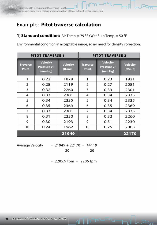
Example: Pitot traverse calculation
1) Standard condition: Air Temp. = 79 oF ; Wet Bulb Temp. = 50 oF
Environmental condition in acceptable range, so no need for density correction.
Average Velocity = 21949 + 22170 = 44119
20 20
= 2205.9 fpm = 2206 fpm
PIToT TRaVERSE 1
Traverse
Point
Velocity
Pressure VP
(mm Hg)
Velocity
(ft/min)
Traverse
Point
Velocity
Pressure VP
(mm Hg)
Velocity
(ft/min)
PIToT TRaVERSE 2
1
2
3
4
5
6
7
8
9
10
1
2
3
4
5
6
7
8
9
10
0.22
0.28
0.32
0.33
0.34
0.35
0.33
0.31
0.30
0.24
1879
2119
2260
2301
2335
2369
2301
2230
2193
1962
21949
0.23
0.27
0.33
0.34
0.34
0.35
0.34
0.32
0.31
0.25
1921
2081
2301
2335
2335
2369
2335
2260
2230
2003
22170
49Department Of Occupational Safety and Health
Guidelines On Occupational Safety and Healthfor design, Inspection, Testing and examination of local exhoust ventilation system
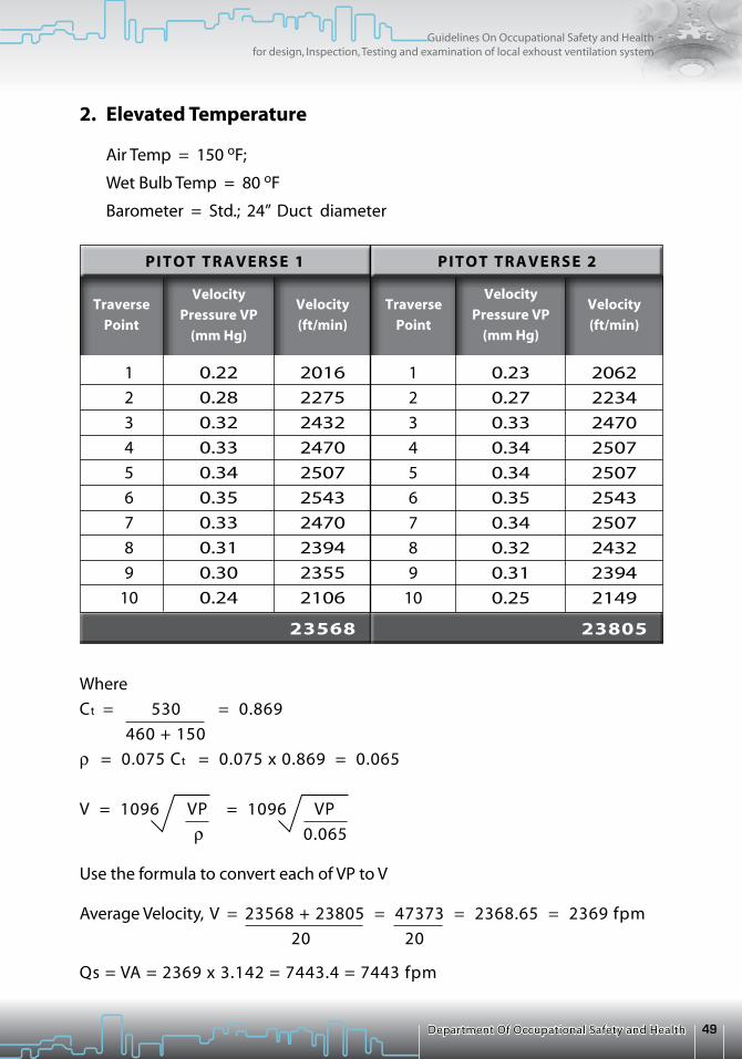
Where
Ct = 530 = 0.869
460 + 150
r = 0.075 Ct = 0.075 x 0.869 = 0.065
V = 1096 VP = 1096 VP
r 0.065
Use the formula to convert each of VP to V
Average Velocity, V = 23568 + 23805 = 47373 = 2368.65 = 2369 fpm
20 20
Qs = VA = 2369 x 3.142 = 7443.4 = 7443 fpm
PIToT TRaVERSE 1
Traverse
Point
Velocity
Pressure VP
(mm Hg)
Velocity
(ft/min)
Traverse
Point
Velocity
Pressure VP
(mm Hg)
Velocity
(ft/min)
PIToT TRaVERSE 2
2. Elevated Temperature
Air Temp = 150 oF;
Wet Bulb Temp = 80 oF
Barometer = Std.; 24” Duct diameter
0.22
0.28
0.32
0.33
0.34
0.35
0.33
0.31
0.30
0.24
2016
2275
2432
2470
2507
2543
2470
2394
2355
2106
23568
0.23
0.27
0.33
0.34
0.34
0.35
0.34
0.32
0.31
0.25
2062
2234
2470
2507
2507
2543
2507
2432
2394
2149
23805
1
2
3
4
5
6
7
8
9
10
1
2
3
4
5
6
7
8
9
10

50 Department Of Occupational Safety and Health
Guidelines On Occupational Safety and Healthfor design, Inspection, Testing and examination of local exhoust ventilation system
APPENDIX C: METHoD oF MEaSUREMENT
ToTal PRESSURE = STaTIc PRESSURE + VElocITY PRESSURE
ToTal PRESSURE BEloW aTMoSPHERE
STaTIc PRESSUREBEloW aTMoSPHERE
VElocITY PRESSURE
Figure 13 : Method Of Measurement With Pitot Tube

51Department Of Occupational Safety and Health
Guidelines On Occupational Safety and Healthfor design, Inspection, Testing and examination of local exhoust ventilation system
ANSI Z33.1-1982NFPA 91-1983
ANSI Z9.2-1979
ANSI Z9.1-1977
ANSI Z9.3-1964
ANSI Z9.4-1979ANSI Z9.4A-1981
ANSI Z9.5-1992
Fans
AMCA 99-83ANSI/UL 507-1976
ASHRAE 51-75AMCA 210-74
ANSI/ASHRAE87.7-1983
AMCA 210-74
AMCA 99-2404-78
AMCA 99-2406-83
NFPA
AIHA
AIHAASHRAE
ANSI
ANSI
AIHA
AMCAUL
ASHRAE
ASHRAE
AMCA
AMCA
AMCA
Installation of Blower and Exhaust Systems for Dust, Stock, Vapour Removal or Conveying (1983)
Fundamentals Governing the Design and Operation of Local Exhaust Systems
Practices for Ventilation and Operation of Open-Surface Tanks
Safety Code for Design, Construction, and Ventilation of Spray Finishing Operations (reaffirmed 1971)
Ventilation and Safe Practices of Abrasives Blasting Operations
Laboratory Ventilation
Standards Handbook Electric Fans (1977)
Laboratory Methods of Testing Fans for Rating
Methods of Testing Dynamic Characteristics of Propeller Fans--Aerodynamically Excited Fan Vibrations and Critical Speeds
Laboratory Methods of Testing Fans for Rating Purposes
Drive Arrangement for Centrifugal Fans
Designation for Rotation and Discharge of Centrifugal Fans
APPENDIX D: lIST oF STaNDaRD FoR DESIGNING oF local EXHaUST VENTIlaTIoN SYSTEM
Exhaust systems

52 Department Of Occupational Safety and Health
Guidelines On Occupational Safety and Healthfor design, Inspection, Testing and examination of local exhoust ventilation system
AMCA
AMCA
SMACNA
SMACNA
ACGIH
AIHA
AMCA
ANSI
ASHRAE
NFPA
SMACNA
UL
Motor Positions for Belt or Chain Drive Centrifugal Fans
Drive Arrangement for Tubular Centrifugal Fans
Round Industrial Duct Construction
Rectangular Industrial Duct Construction
American Conference of Governmental Industrial Hygienists6500 Glenway Ave., Bldg. D-5 Cincinnati, OH 45211
American Industrial Hygiene Association2700 Prosperity Ave., Suite 250 Fairfax, VA 22031-4319
Air Movement and Control Association30 W. University Dr. Arlington Heights, IL 60004
American National Standards Institute1430 Broadway New York, NY 10018
American Society of Heating, Refrigeration and Air-Conditioning Engineers, Inc.1791 Tullie Circle, N.E., Atlanta, GA 30329
National Fire Protection AssociationBatterymarch Park Quincy, MA 02269
Sheet Metal and Air Conditioning Contractors’ National Association8224 Old Courthouse Rd.Vienna, VA 22180
Underwriters Laboratories Inc.333 Pfingsten Rd. Northbrook, IL 60062
AMCA 99-2407-66
AMCA 99-2410-82
Industrial Duct
SMACNA
SMACNA
SoURcES oF STaNDaRDS
Source organization

53Department Of Occupational Safety and Health
Guidelines On Occupational Safety and Healthfor design, Inspection, Testing and examination of local exhoust ventilation system
Department Of Occupational Safety and Health (DOSH)
Ministry of Human Resources
Level 2,3 & 4, Block D3, Complex D,
Federal Government Administrative Centre
62530 Putrajaya.
on Occupational Safety and Health
for Design, Inspection, Testing and Examination
of Local Exhaust Ventilation System
Department Of Occupat ional Safety and HealthMinistry of Human Resources
Malays ia2008
G U I D E L I N E S
JKKP DP 127/37914-46ISBN 978-983-2014-60-7


