Download - On-board computer AMATRON - AMAZONE

Operating Manual
az
On-board computer AMATRON+
ZA-M
MG3685 BAG0063.1 03.10 Printed in Germany
Please read this operating manual before first
commissioning. Keep it in a safe place for
future use.
en

2 Amatron+ BAG0063.1 03.10
Reading the instruction Manual and following it should seem to be in-convenient and superfluous as it is not enough to hear from others and to realize that a machine is good, to buy it and to believe that now everything should work by itself. The person in question would not only harm himself but also make the mistake of blaming the machine for pos-sible failures instead of himself. In order to ensure success one should enter the mind of a thing, make himself familiar with every part of the ma-chine and get acquainted with how it's handled. Only in this way could you be satisfied both with the machine and with yourself. This goal is the purpose of this instruction manual.
Leipzig-Plagwitz 1872.
Identification data
Amatron+ BAG0063.1 03.10 3
Identification data
Enter the machine identification data here. You will find the identifica-tion data on the type plate.
Machine identification number: (ten-digit)
Type: Amatron+
Year of manufacture:
Basic weight (kg):
Approved total weight (kg):
Maximum load (kg):
Manufacturer's address
AMAZONEN-WERKE
H. DREYER GmbH & Co. KG
Postfach 51
D-49202
Tel.:
Fax:
E-mail:
Hasbergen
+ 49 (0)5405 501-0
+ 49 (0)5405 501-234
Spare part orders
Spare parts lists are freely accessible in the spare parts portal at www.amazone.de.
Please send orders to your AMAZONE dealer.
Formalities of the operating manual
Document number: MG3685
Compilation date: 03.10
Copyright AMAZONEN-WERKE H. DREYER GmbH & Co. KG, 2010
All rights reserved.
Reprinting, even of sections, only possible with the approval of AMAZONEN-WERKE H. DREYER GmbH & Co. KG.

Foreword
4 Amatron+ BAG0063.1 03.10
Foreword
Dear Customer,
You have chosen one of the quality products from the wide product range of AMAZONEN-WERKE, H. DREYER GmbH & Co. KG. We thank you for your confidence in our products.
On receiving the machine, check to see if it was damaged during transport or if parts are missing. Using the delivery note, check that the machine was delivered in full including the ordered special equip-ment. Damage can only be rectified if problems are signalled immedi-ately!
Before first commissioning, read and understand this operating man-ual, and particularly the safety information. Only after careful reading will you be able to benefit from the full scope of your newly purchased machine.
Please ensure that all the machine operators have read this operating manual before commissioning the machine.
Should you have problems or queries, please consult this operating manual or give us a call.
Regular maintenance and timely replacement of worn or damaged parts increases the lifespan of your machine.
User evaluation
Dear Reader,
We update our operating manuals regularly. Your suggestions for improvement help us to create ever more user-friendly manuals. Send us your suggestions by fax.
AMAZONEN-WERKE
H. DREYER GmbH & Co. KG
Postfach 51
D-49202
Tel.:
Fax:
E-mail:
Hasbergen
+ 49 (0)5405 501-0
+ 49 (0)5405 501-234

Table of Contents
Amatron+ BAG0063.1 03.10 5
1 User Information ..........................................................................................7 1.1 Purpose of the document.........................................................................................................7 1.2 Locations in the operating manual...........................................................................................7 1.3 Diagrams used.........................................................................................................................7
2 General safety instructions.........................................................................8 2.1 Representation of safety symbols............................................................................................8
3 Installation instructions ..............................................................................9 3.1 Connection...............................................................................................................................9 3.2 Battery cable ..........................................................................................................................10
4 Product description ...................................................................................11 4.1 Keys and function fields .........................................................................................................12 4.1.1 Shift key .................................................................................................................................13 4.2 Entries on AMATRON+ ....................................................................................................14 4.3 Entering text and numbers.....................................................................................................14 4.3.1 Selection of options................................................................................................................15 4.3.2 Toggle function ......................................................................................................................15 4.4 Software version ....................................................................................................................15 4.5 Hierarchy of the AMATRON+...........................................................................................16
5 Commissioning..........................................................................................17 5.1 Start screen............................................................................................................................17 5.2 Main menu .............................................................................................................................17 5.3 Entering machine data ...........................................................................................................19
5.3.1 Configuring quantity reduction (machine data ) .......................................................21
5.3.2 Calibrating distance sensor (machine data )...........................................................22
5.3.3 Entering power take-off speed (machine data ) ......................................................23 5.4 Starting a job..........................................................................................................................25 5.4.1 External job ............................................................................................................................26 5.5 Calibrating fertiliser ................................................................................................................27 5.5.1 Determining fertiliser calibration factor at standstill ...............................................................28 5.5.2 Conduct fertiliser calibration run (offline calibration)..............................................................30 5.5.3 Calibrate permanent fertiliser (online calibration) ..................................................................32 5.5.4 Calibration of slug pellets.......................................................................................................34 5.6 Service Setup.........................................................................................................................37 5.6.1 Taring/calibrating weighing cell..............................................................................................39 5.7 Terminal set-up ......................................................................................................................40 5.8 Mobile test rig.........................................................................................................................42
6 Use on the field ..........................................................................................43 6.1 Work menu display ................................................................................................................44 6.2 Functions in work menu .........................................................................................................45 6.2.1 Slide gate (ZA-M Comfort, Hydro only) ..................................................................45 6.2.2 Boundary spreading with limiter.............................................................................................45 6.2.3 Changing spread quantity left/right ........................................................................................46 6.2.4 Tarpaulin (ZA-M Comfort, Hydro only) ...................................................................46 6.2.5 Calibrating fertiliser (ZA-M Profis only) .........................................................................47 6.2.6 Filling with fertiliser.................................................................................................................47 6.2.7 Switching spreading disc drive on and off (ZA-M Hydro only).......................................48 6.2.8 Boom part width sections (ZA-M Hydro only)................................................................49 6.2.9 Boundary spreading (ZA-M Hydro only) ........................................................................50 6.3 ZA-M Tronic ..................................................................................................................51 6.3.1 Procedure for use ..................................................................................................................51 6.3.2 Work menu key layout ...........................................................................................................51

Table of Contents
6 Amatron+ BAG0063.1 03.10
6.4 ZA-M Comfort ............................................................................................................. 53 6.4.1 Procedure for use.................................................................................................................. 53 6.4.2 Work menu key layout........................................................................................................... 54 6.5 ZA-M Hydro................................................................................................................... 56 6.5.1 Procedure for use.................................................................................................................. 56 6.5.2 Work menu key layout........................................................................................................... 57 6.6 Filling with fertiliser ................................................................................................................ 59 6.7 Emptying fertiliser hopper ..................................................................................................... 60
7 Multifunction stick..................................................................................... 61 7.1 Installation ............................................................................................................................. 61 7.2 Function................................................................................................................................. 61 7.3 Key layout:............................................................................................................................. 62
8 Maintenance and cleaning........................................................................ 63 8.1 Cleaning ................................................................................................................................ 63 8.2 Basic slide setting.................................................................................................................. 63
9 Malfunction ................................................................................................ 65 9.1 Alarm ..................................................................................................................................... 65 9.2 Error messages and remedies .............................................................................................. 66 9.3 Failure of setting motors........................................................................................................ 70 9.4 Distance sensor (pulses/100 m failure)................................................................................. 71

User Information
Amatron+ BAG0063.1 03.10 7
1 User Information
The User Information section supplies information on use of the oper-ating manual.
1.1 Purpose of the document
This operating manual
Describes the operation and maintenance of the machine.
Provides important information on safe and efficient handling of the machine.
Is a component part of the machine and should always be kept with the machine or the traction vehicle.
Keep it in a safe place for future use.
1.2 Locations in the operating manual
All the directions specified in the operating manual are always seen from the direction of travel.
1.3 Diagrams used
Handling instructions and reactions
Activities to be carried out by the user are given as numbered instruc-tions. Always keep to the order of the handling instructions. The reac-tion to the handling instructions is given by an arrow.
Example:
1. Handling instruction 1
→ Reaction of the machine to handling instruction 1
2. Handling instruction 2
Lists
Lists without an essential order are shown as a list with bullets.
Example:
Point 1
Point 2
Number items in diagrams
Numbers in round brackets refer to the item numbers in the diagrams. The first number refers to the diagram and the second number to the item in the figure.
Example: (Fig. 3/6)
Figure 3
Item 6

General safety instructions
8 Amatron+ BAG0063.1 03.10
2 General safety instructions
Knowledge of the basic safety information and safety regulations is a basic requirement for safe handling and fault-free machine operation.
The operation manual
Must always be kept at the place at which the machine is oper-ated.
Must always be easily accessible for the user and maintenance personnel.
2.1 Representation of safety symbols
Safety instructions are indicated by the triangular safety symbol and the highlighted signal word. The signal word (DANGER, WARNING, CAUTION) describes the gravity of the risk and has the following sig-nificance:
DANGER
Indicates an immediate high risk which will result in death or serious physical injury (loss of body parts or long term damage) if not avoided.
If the instructions are not followed, then this will result in imme-diate death or serious physical injury.
WARNING
Indicates a medium risk, which could result in death or (serious) physical injury if not avoided.
If the instructions are not followed, then this may result in death or serious physical injury.
CAUTION
Indicates a low risk which could incur minor or medium level physical injury or damage to property if not avoided.
IMPORTANT
Indicates an obligation to special behaviour or an activity re-quired for proper machine handling.
Non-compliance with these instructions can cause faults on the machine or in the environment.
NOTE
Indicates handling tips and particularly useful information.
These instructions will help you to use all the functions of your machine to the optimum.

Installation instructions
Amatron+ BAG0063.1 03.10 9
3 Installation instructions
3.1 Connection
The tractor's basic equipment (Fig. 1/1 console with distributor) must be installed to the right of the driver in the cab, within visual range and easy reach, so that it is vibration-free and electrically conductive.
Remove the paint from the mounting points to prevent electro-static charging.
The distance from the radio unit or aerial must be at least 1 m.
Fig. 1
Connections to tractor's basic equipment:
The battery cable (Fig. 1/5).
Signal cable from the tractor signal socket or distance sensor (Fig. 1/4).
Connecting cable to AMATRON+ (Fig. 1/6).
To operate
Plug the AMATRON+ (Fig. 1/2) into the tractor's basic equipment.
Insert the connector of the connecting cable (Fig. 1/6) into the middle 9-pin Sub-D bush-ing (Fig. 2/1).
Connect the machine via the connector (Fig. 1/3) to the AMATRON+.
The multifunction stick (Fig. 1/7) is con-nected using a Y-cable (Fig. 1/8).
The serial interface (Fig. 2/2) allows a PDA to be connected.
Fig. 2
Installation instructions
10 Amatron+ BAG0063.1 03.10
3.2 Battery cable
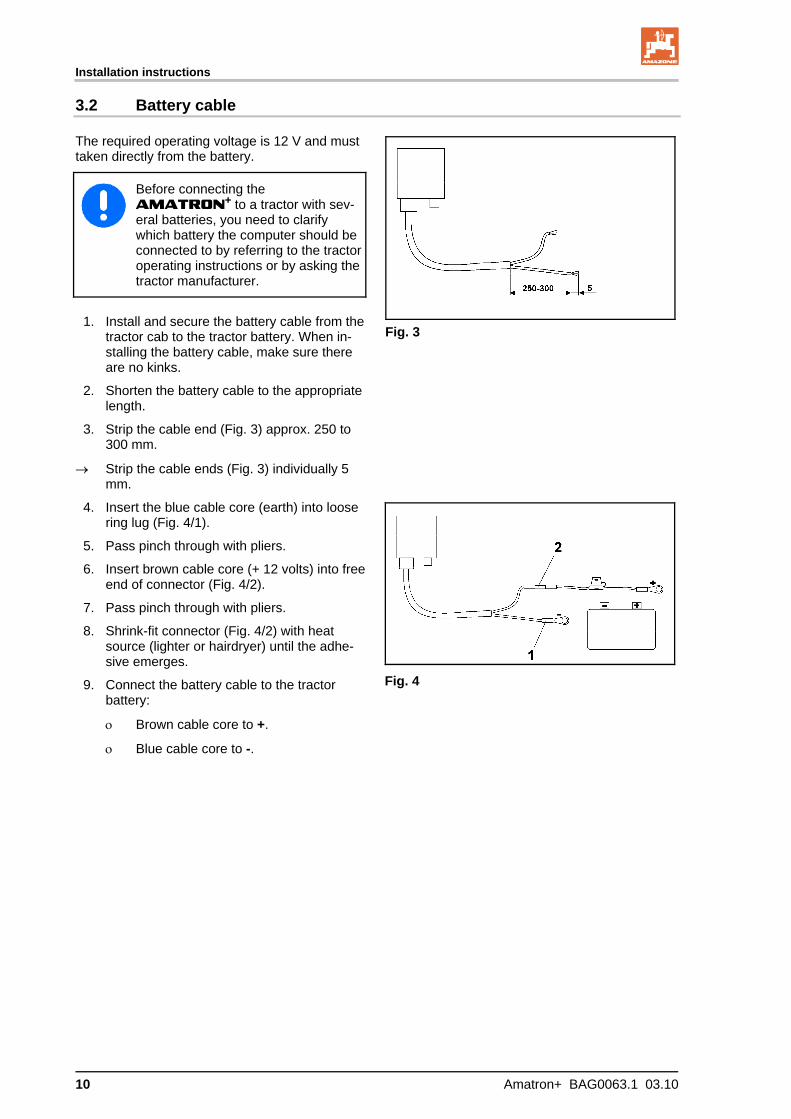
The required operating voltage is 12 V and must taken directly from the battery.
Before connecting the AMATRON+ to a tractor with sev-eral batteries, you need to clarify which battery the computer should be connected to by referring to the tractor operating instructions or by asking the tractor manufacturer.
1. Install and secure the battery cable from the tractor cab to the tractor battery. When in-stalling the battery cable, make sure there are no kinks.
2. Shorten the battery cable to the appropriate length.
3. Strip the cable end (Fig. 3) approx. 250 to 300 mm.
Strip the cable ends (Fig. 3) individually 5 mm.
Fig. 3
4. Insert the blue cable core (earth) into loose ring lug (Fig. 4/1).
5. Pass pinch through with pliers.
6. Insert brown cable core (+ 12 volts) into free end of connector (Fig. 4/2).
7. Pass pinch through with pliers.
8. Shrink-fit connector (Fig. 4/2) with heat source (lighter or hairdryer) until the adhe-sive emerges.
9. Connect the battery cable to the tractor battery:
Brown cable core to +.
Blue cable core to -.
Fig. 4

Product description
Amatron+ BAG0063.1 03.10 11
4 Product description
The AMATRON+ makes it easy to control, operate and monitor the AMAZONE ZA-M fertiliser spreader.
The AMATRON+ can be used for various machine types.
The AMATRON+ works with the following AMAZONE fertiliser spreaders:
ZA-M Tronic with power take-off
ZA-M Comfort
with hydraulic control block for the slide gate, limiter and tarpaulin (depending on configuration)
with power take-off
ZA-M Hydro
with hydraulic spreading disc drive with hydraulic control block for the slide gate, limiter and
tarpaulin (depending on configuration) with weighing equipment.
ZA-M Profis with weighing equipment.
The AMATRON+ regulates the spread rate as a factor of travel speed. Depending on the machine and its configuration, a press of a but-ton allows you:
to change the spread rate into pre-specified steps (e.g. +/- 10%)
to calibrate the amount of fertiliser while driving (weighing spreader only)
easy boundary spreading
wedge-shaped field spreading (ZA-M hydro only).
Main menu (Fig. 5)
The main menu contains several submenus for making settings before starting work, such as
entering details,
determining or entering settings.
Work menu (Fig. 6)
The work menu displays all necessary spreading details as you go.
It is used to control the machine as you work.
Fig. 5
Fig. 6
Product description
12 Amatron+ BAG0063.1 03.10
4.1 Keys and function fields
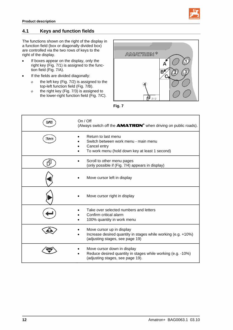
The functions shown on the right of the display in a function field (box or diagonally divided box) are controlled via the two rows of keys to the right of the display.
If boxes appear on the display, only the right key (Fig. 7/1) is assigned to the func-tion field (Fig. 7/A).
If the fields are divided diagonally:
the left key (Fig. 7/2) is assigned to the top-left function field (Fig. 7/B).
the right key (Fig. 7/3) is assigned to the lower-right function field (Fig. 7/C).
Fig. 7
On / Off (Always switch off the AMATRON+ when driving on public roads).
Return to last menu Switch between work menu - main menu Cancel entry To work menu (hold down key at least 1 second)
Scroll to other menu pages (only possible if (Fig. 7/4) appears in display)
Move cursor left in display
Move cursor right in display
Take over selected numbers and letters Confirm critical alarm 100% quantity in work menu
Move cursor up in display Increase desired quantity in stages while working (e.g. +10%)
(adjusting stages, see page 19)
Move cursor down in display Reduce desired quantity in stages while working (e.g. -10%)
(adjusting stages, see page 19).
Product description
Amatron+ BAG0063.1 03.10 13
4.1.1 Shift key
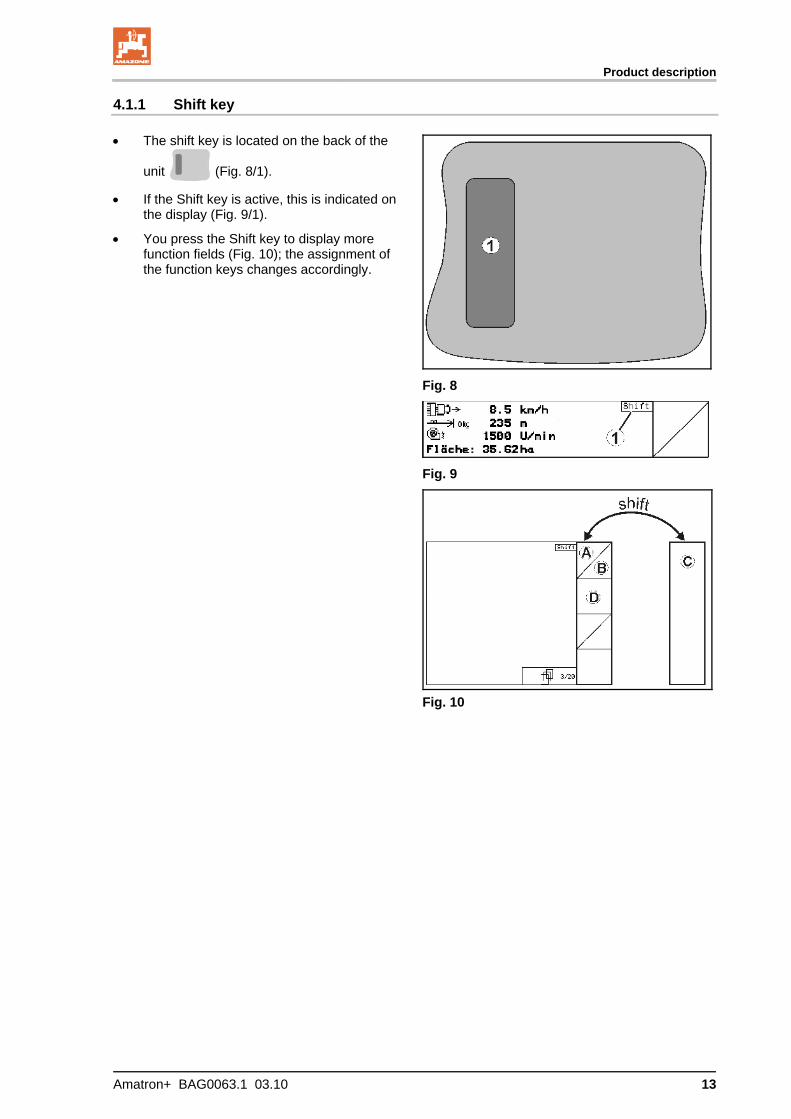
The shift key is located on the back of the
unit (Fig. 8/1).
If the Shift key is active, this is indicated on the display (Fig. 9/1).
You press the Shift key to display more function fields (Fig. 10); the assignment of the function keys changes accordingly.
Fig. 8
Fig. 9
Fig. 10
Product description
14 Amatron+ BAG0063.1 03.10
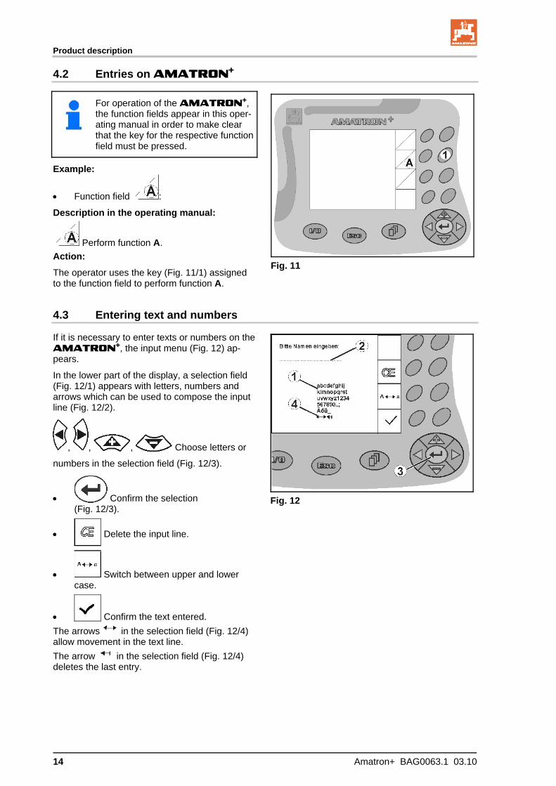
4.2 Entries on AMATRON+
For operation of the AMATRON+, the function fields appear in this oper-ating manual in order to make clear that the key for the respective function field must be pressed.
Example:
Function field :
Description in the operating manual:
Perform function A.
Action:
The operator uses the key (Fig. 11/1) assigned to the function field to perform function A.
Fig. 11
4.3 Entering text and numbers
If it is necessary to enter texts or numbers on the AMATRON+, the input menu (Fig. 12) ap-pears.
In the lower part of the display, a selection field (Fig. 12/1) appears with letters, numbers and arrows which can be used to compose the input line (Fig. 12/2).
, , , Choose letters or
numbers in the selection field (Fig. 12/3).
Confirm the selection (Fig. 12/3).
Delete the input line.
Switch between upper and lower case.
Confirm the text entered.
The arrows in the selection field (Fig. 12/4) allow movement in the text line.
The arrow in the selection field (Fig. 12/4) deletes the last entry.
Fig. 12
Product description
Amatron+ BAG0063.1 03.10 15
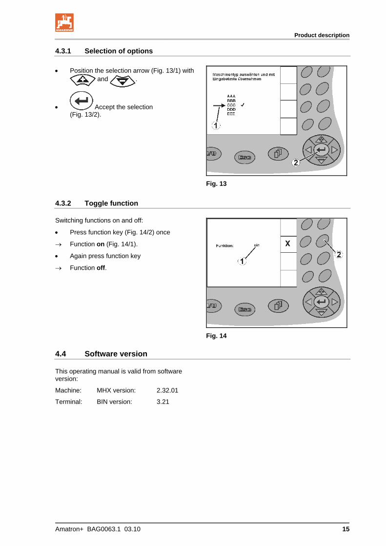
4.3.1 Selection of options
Position the selection arrow (Fig. 13/1) with and .
Accept the selection (Fig. 13/2).
Fig. 13
4.3.2 Toggle function
Switching functions on and off:
Press function key (Fig. 14/2) once
Function on (Fig. 14/1).
Again press function key
Function off.
Fig. 14
4.4 Software version
This operating manual is valid from software version:
Machine: MHX version: 2.32.01
Terminal: BIN version: 3.21

Product description
16 Amatron+ BAG0063.1 03.10
4.5 Hierarchy of the AMATRON+
Work menu Main menu
Job menu Fertiliser calibration menu (at standstill)
Enter names
Enter note
Start/continue job
Delete job
Enter spread quantity
Delete daily data
Enter working width
Enter desired quantity
Enter speed
Enter calibration factors
Perform fertiliser calibration
Set slug pellets
Machine data menu Service set-up menu (for service personnel only)
Mobile test rig
Fertiliser level
Top up fertiliser
Fertiliser alarm limit
Empty hopper
Configure quantity change
calibrate pulses per 100 m
Change specified power take-off speed
Headland row counter
Calibrate slug pellets / Select rice
Tare spreader
Calibrate online / offline
Nominal disc speed
Disc speed
- Boundary spreading - Edge spreading - Trench spreading
Diagnosis input
Diagnosis output
Simulated speed
Select basic data
- Machine type - Weighing cell - Calibrate weighing cell - Basic setting for sliders - Hydraulically operated tarpau-
lin - Limiter present - slide gate (double effect, sin-
gle effect) - Control factor - RESET
Set-up: display settings
Commissioning
Amatron+ BAG0063.1 03.10 17
5 Commissioning
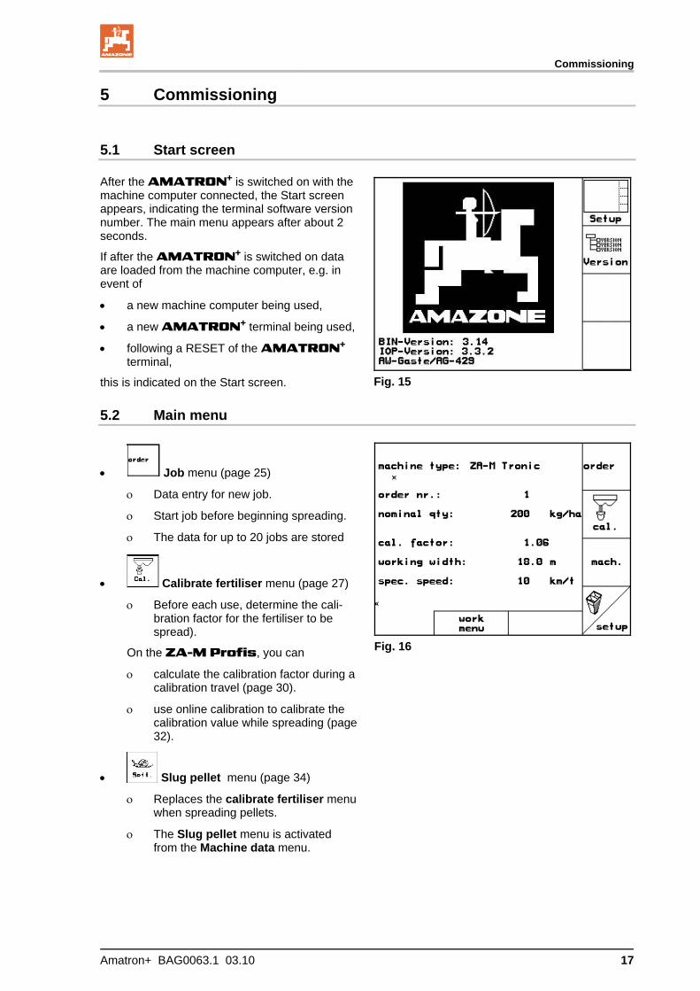
5.1 Start screen
After the AMATRON+ is switched on with the machine computer connected, the Start screen appears, indicating the terminal software version number. The main menu appears after about 2 seconds.
If after the AMATRON+ is switched on data are loaded from the machine computer, e.g. in event of
a new machine computer being used,
a new AMATRON+ terminal being used,
following a RESET of the AMATRON+ terminal,
this is indicated on the Start screen.
Fig. 15
5.2 Main menu
Fig. 16
Job menu (page 25)
Data entry for new job.
Start job before beginning spreading.
The data for up to 20 jobs are stored
Calibrate fertiliser menu (page 27)
Before each use, determine the cali-bration factor for the fertiliser to be spread).
On the ZA-M Profis, you can
calculate the calibration factor during a calibration travel (page 30).
use online calibration to calibrate the calibration value while spreading (page32).
Slug pellet menu (page 34)
Replaces the calibrate fertiliser menu when spreading pellets.
The Slug pellet menu is activated from the Machine data menu.
Commissioning
18 Amatron+ BAG0063.1 03.10
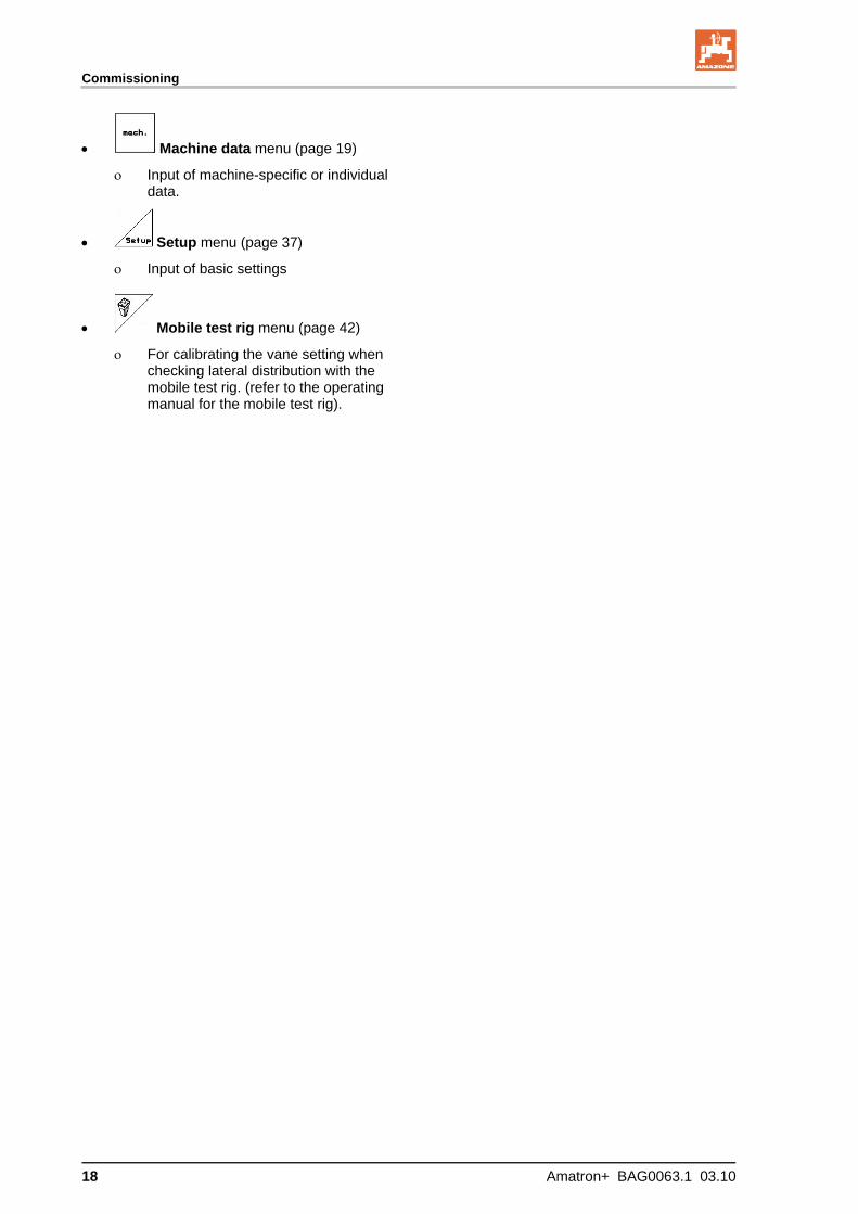
Machine data menu (page 19)
Input of machine-specific or individual data.
Setup menu (page 37)
Input of basic settings
Mobile test rig menu (page 42)
For calibrating the vane setting when checking lateral distribution with the mobile test rig. (refer to the operating manual for the mobile test rig).
Commissioning
Amatron+ BAG0063.1 03.10 19
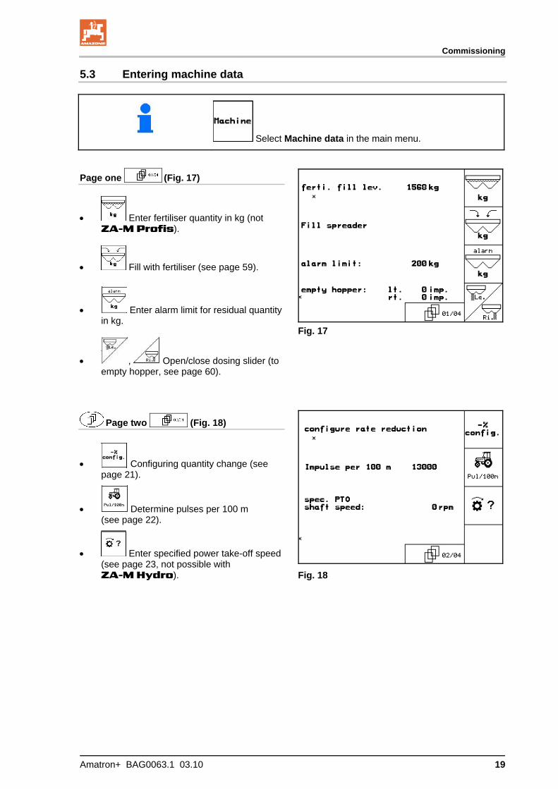
5.3 Entering machine data
Select Machine data in the main menu.
Page one (Fig. 17)
Enter fertiliser quantity in kg (not ZA-M Profis).
Fill with fertiliser (see page 59).
Enter alarm limit for residual quantity in kg.
, Open/close dosing slider (to empty hopper, see page 60).
Fig. 17
Page two (Fig. 18)
Configuring quantity change (see page 21).
Determine pulses per 100 m (see page 22).
Enter specified power take-off speed (see page 23, not possible with ZA-M Hydro).
Fig. 18
Commissioning
20 Amatron+ BAG0063.1 03.10
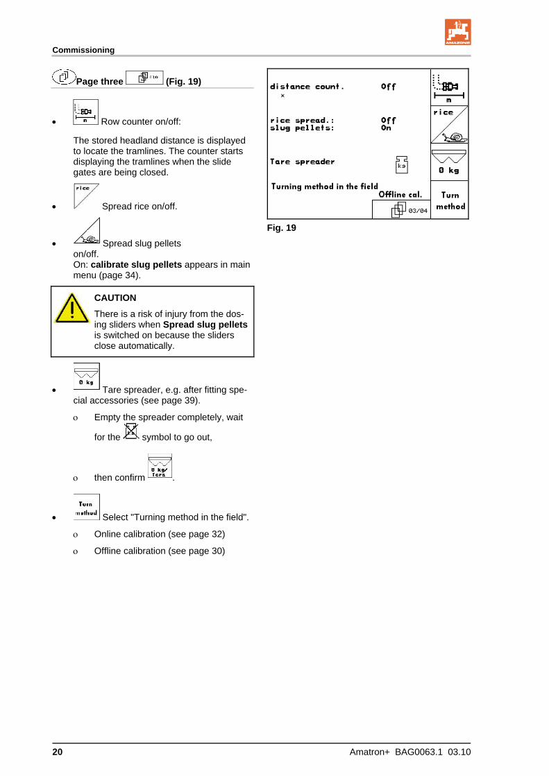
Page three (Fig. 19)
Row counter on/off:
The stored headland distance is displayed to locate the tramlines. The counter starts displaying the tramlines when the slide gates are being closed.
Spread rice on/off.
Spread slug pellets on/off. On: calibrate slug pellets appears in main menu (page 34).
Fig. 19
CAUTION
There is a risk of injury from the dos-ing sliders when Spread slug pellets is switched on because the sliders close automatically.
Tare spreader, e.g. after fitting spe-cial accessories (see page 39).
Empty the spreader completely, wait
for the symbol to go out,
then confirm .
Select "Turning method in the field".
Online calibration (see page 32)
Offline calibration (see page 30)

Commissioning
Amatron+ BAG0063.1 03.10 21
Page four (Fig. 20)
ZA-M Hydro
: enter spreader disc speed in rpm (see settings chart, standard = 720 rpm.)
Spreader disc speed in rpm for boundary spreading.
Spreader disc speed in rpm for trench spreading.
Spreader disc speed in rpm for side spreading.
Fig. 20
5.3.1 Configuring quantity reduction (machine data )
Enter percentage application rate increase (value for percent change while working).
all ZA-Ms: quantity reduction dur-ing boundary spreading
ZA-M Hydro: quantity reduction during trench spreading
ZA-M Hydro: quantity reduction during side spreading
Fig. 21
Commissioning
22 Amatron+ BAG0063.1 03.10
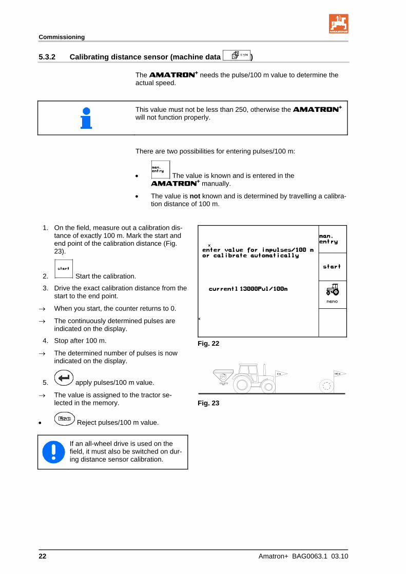
5.3.2 Calibrating distance sensor (machine data )
The AMATRON+ needs the pulse/100 m value to determine the actual speed.
This value must not be less than 250, otherwise the AMATRON+
will not function properly.
There are two possibilities for entering pulses/100 m:
The value is known and is entered in the AMATRON+ manually.
The value is not known and is determined by travelling a calibra-tion distance of 100 m.
1. On the field, measure out a calibration dis-tance of exactly 100 m. Mark the start and end point of the calibration distance (Fig. 23).
2. Start the calibration.
3. Drive the exact calibration distance from the start to the end point.
When you start, the counter returns to 0.
The continuously determined pulses are indicated on the display.
4. Stop after 100 m.
The determined number of pulses is now indicated on the display.
5. apply pulses/100 m value.
The value is assigned to the tractor se-lected in the memory.
Reject pulses/100 m value.
Fig. 22
Fig. 23
If an all-wheel drive is used on the field, it must also be switched on dur-ing distance sensor calibration.
Commissioning
Amatron+ BAG0063.1 03.10 23
The pulse/100 m value can be stored for 3 tractors:
1. , Select tractor
2. Enter/change name
3. Enter pulse/100 m for selected trac-tor
If a tractor has already been stored here, its pulse/100 m and power take-off speed values will be used.
Fig. 24
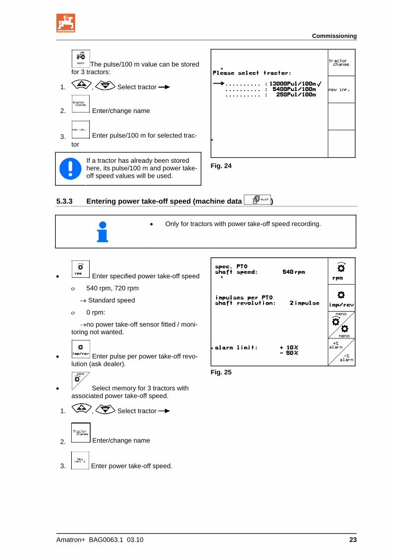
5.3.3 Entering power take-off speed (machine data )
Only for tractors with power take-off speed recording.
Enter specified power take-off speed
540 rpm, 720 rpm
Standard speed
0 rpm:
no power take-off sensor fitted / moni-toring not wanted.
Enter pulse per power take-off revo-lution (ask dealer).
Select memory for 3 tractors with associated power take-off speed.
1. , Select tractor
2. Enter/change name
3. Enter power take-off speed.
Fig. 25
Commissioning
24 Amatron+ BAG0063.1 03.10
Memory for 3 tractors with associ-ated value for pulses/revolution
1. , Select tractor
2. Enter/change name
3. Enter pulses/revolution for power take-off.
4. Enter upper alarm limit in %. (Standard value = 10 %).
5. Enter lower alarm limit in %. (Stan-dard value = 10 %).

Commissioning
Amatron+ BAG0063.1 03.10 25
5.4 Starting a job
Select Job in main menu.
When the Job menu is opened, the most recently started (most recently processed) job appears.
Information on max. 20 jobs can be stored (job numbers 1 to 20).
To create a new job, select a job number (Fig. 26/1).
Enter name
Enter note
Enter desired quantity
Start the job so that data can be stored with this job.
Delete the data for the selected job
Delete daily data
Worked area (ha/day)
Fertiliser quantity dispensed (quan-tity/day)
Work time (hours/day).
Fig. 26
Already stored jobs can be called up
with and restarted with .

Commissioning
26 Amatron+ BAG0063.1 03.10
With the shift key pressed (Fig. 27):
Scroll forward through job.
Scroll backward through job.
Fig. 27
5.4.1 External job
Using a PDA, an external job can be transferred to the AMATRON+ and then started.
This job is always given the job number 21.
The data is transferred via the serial interface.
End the external job.
Fig. 28
Commissioning
Amatron+ BAG0063.1 03.10 27
5.5 Calibrating fertiliser
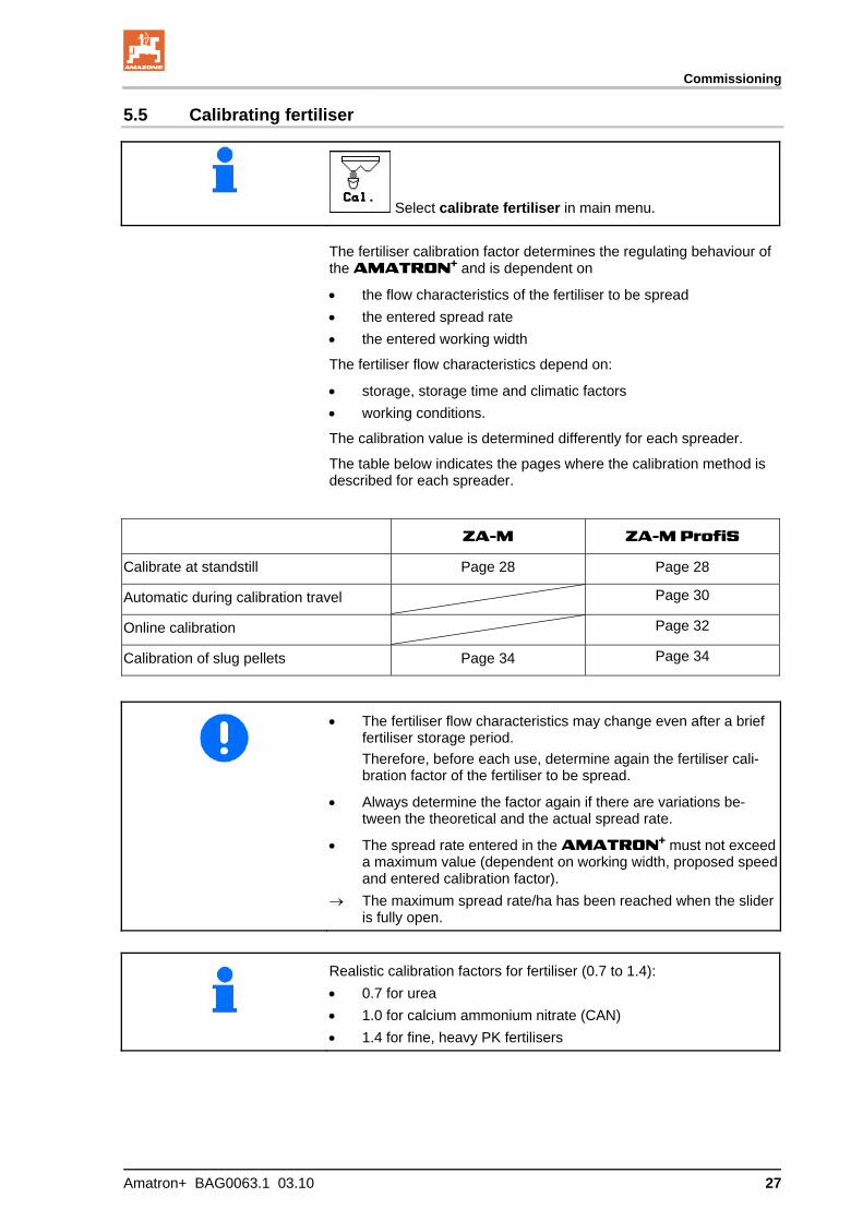
Select calibrate fertiliser in main menu.
The fertiliser calibration factor determines the regulating behaviour of
the AMATRON+ and is dependent on
the flow characteristics of the fertiliser to be spread
the entered spread rate
the entered working width
The fertiliser flow characteristics depend on:
storage, storage time and climatic factors
working conditions.
The calibration value is determined differently for each spreader.
The table below indicates the pages where the calibration method is described for each spreader.
ZA-M ZA-M ProfiS
Calibrate at standstill Page 28 Page 28
Automatic during calibration travel Page 30
Online calibration Page 32
Calibration of slug pellets Page 34 Page 34
The fertiliser flow characteristics may change even after a brief fertiliser storage period.
Therefore, before each use, determine again the fertiliser cali-bration factor of the fertiliser to be spread.
Always determine the factor again if there are variations be-tween the theoretical and the actual spread rate.
The spread rate entered in the AMATRON+ must not exceed a maximum value (dependent on working width, proposed speed and entered calibration factor).
The maximum spread rate/ha has been reached when the slider is fully open.
Realistic calibration factors for fertiliser (0.7 to 1.4):
0.7 for urea
1.0 for calcium ammonium nitrate (CAN)
1.4 for fine, heavy PK fertilisers

Commissioning
28 Amatron+ BAG0063.1 03.10
5.5.1 Determining fertiliser calibration factor at standstill
1. Add a sufficient quantity of fertiliser to the hopper.
2. Remove the left spreading disc.
3. Fit collection bucket under the left outlet (refer to ZA-M operating manual).
4. Check/enter the working width.
5. Check/enter the spreading quantity.
6. Check/enter the intended speed.
7. Enter calibration factor for determin-ing exact factor, e.g. 1.00.
The calibration can be
the quantity factor in the settings chart
values based on experience.
Fig. 29
WARNING
Risk of injury from right rotating spreading disc
Keep people away from the discs.
8. Set the power take-off on the tractor as per the settings chart.
ZA-M Hydro: switch on spreader discs.
9. Open the left slide gate.
Operate tractor controller 1.
ZA-M Hydro/Comfort: .
10. Close the left slide gate as soon as the collection bucket is full.
Operate tractor controller 1.
ZA-M Hydro/Comfort: .
11. Switch off spreading disc drive.
Switch off power take-off.
ZA-M Hydro: spreader discs switch off automatically.
12. Weigh the collected fertiliser (allow for the weight of the collection bucket).
Commissioning
Amatron+ BAG0063.1 03.10 29
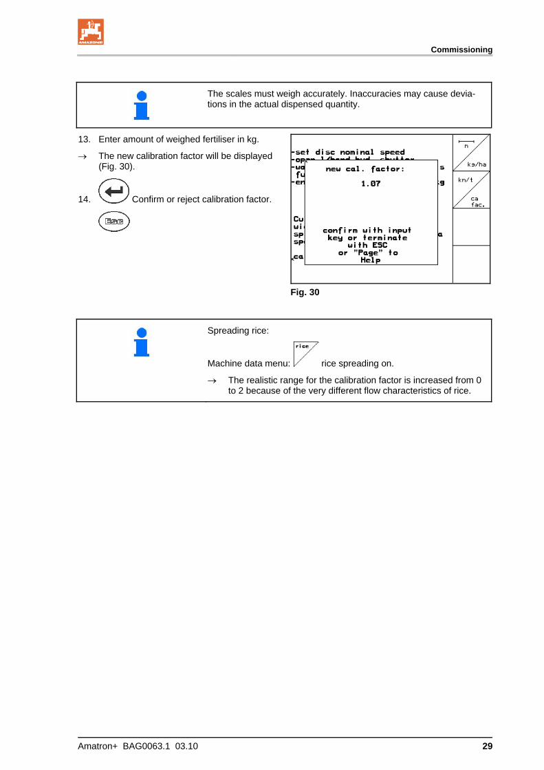
The scales must weigh accurately. Inaccuracies may cause devia-tions in the actual dispensed quantity.
13. Enter amount of weighed fertiliser in kg.
The new calibration factor will be displayed (Fig. 30).
14. Confirm or reject calibration factor.
Fig. 30
Spreading rice:
Machine data menu: rice spreading on.
The realistic range for the calibration factor is increased from 0 to 2 because of the very different flow characteristics of rice.

Commissioning
30 Amatron+ BAG0063.1 03.10
5.5.2 Conduct fertiliser calibration run (offline calibration)
Only for ZA-M Profis:
Automatic fertiliser calibration occurs at the start of sowing during spreading, with a minimum 200 kg fertiliser being dispensed.
Machine data menu , page
three :
Offline calibration mode.
Offline calibration mode activated:
Before automatic fertiliser calibration:
Select the fertiliser calibration menu.
Fig. 31
1. Check/enter the working width.
2. Check/enter the spreading quantity.
3. Check/enter the intended speed.
4. Enter calibration factor for determin-ing exact factor, e.g. 1.00.
To enter the calibration factor:
take the calibration factor (quantity fac-tor) from the settings chart.
values based on experience.
or make the calibration in advance withthe machine at rest (page 28).
Fig. 32
The tractor and spreader must be standing level at the start and end of the calibration process.
The scales must be in their neutral position for the determination of the calibration factor to be started and ended.
If the symbol appears in the display, the spreader is not in its neutral position.

Commissioning
Amatron+ BAG0063.1 03.10 31
Determining fertiliser calibration factor auto-matically
1. Select the work menu.
2. Start automatic calibration.
3. Start spreading as usual and spread at least 200 kg of fertiliser.
The quantity of fertiliser dispensed is shown in the work menu (Fig. 33/1).
The work menu signals when 200 kg of fertiliser have been spread. (Fig. 33/2).
4. Once at least 200 kg of fertiliser has been dispensed, close the slide gates and come to a stop.
5. End automatic calibration.
The new calibration factor will be displayed (Fig. 34).
6. Confirm or reject calibration factor.
Calibration travel can be carried out at any time while working in order to op-timise the calibration factor.
Fig. 33
Fig. 34
Fertiliser calibration by weighing is carried out during spreading operations where at least 200 kg of fertiliser is to be dispensed.
After the first fertiliser calibration, further calibrations should be carried out with greater spreading quantities (e.g. 1000 kg) in order to further optimise the calibration factor.
Commissioning
32 Amatron+ BAG0063.1 03.10
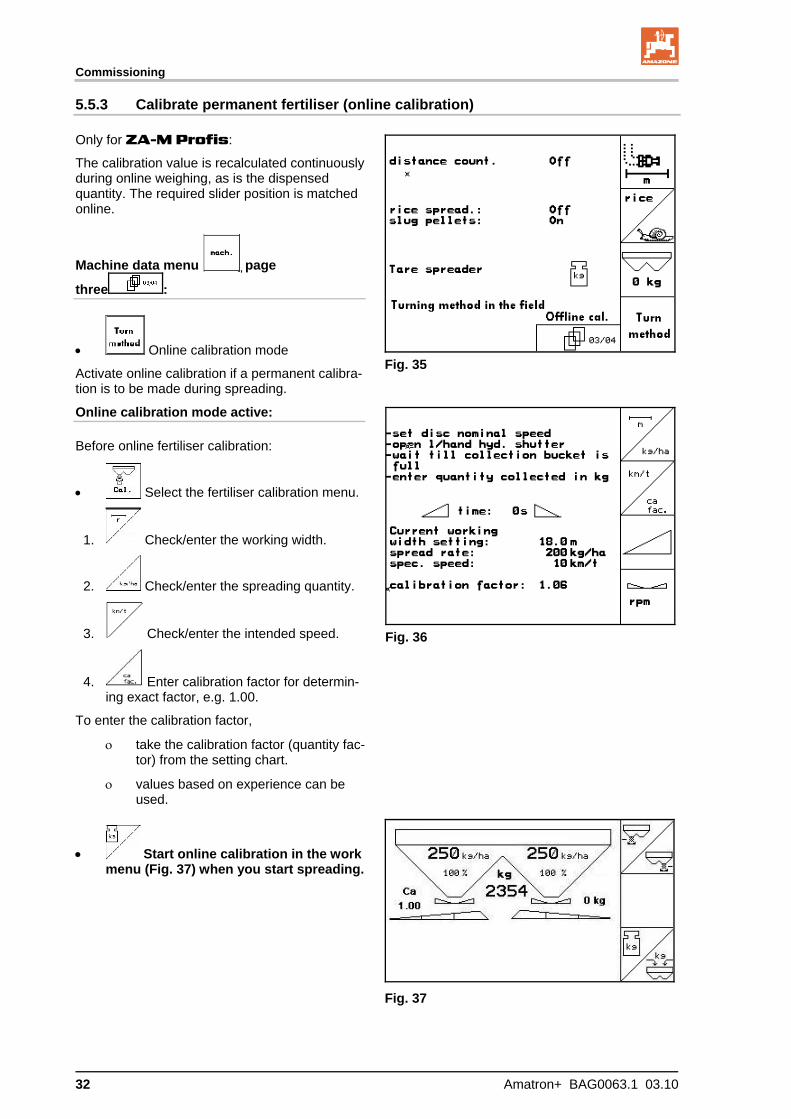
5.5.3 Calibrate permanent fertiliser (online calibration)
Only for ZA-M Profis:
The calibration value is recalculated continuously during online weighing, as is the dispensed quantity. The required slider position is matched online.
Machine data menu , page
three :
Online calibration mode
Activate online calibration if a permanent calibra-tion is to be made during spreading.
Fig. 35
Online calibration mode active:
Before online fertiliser calibration:
Select the fertiliser calibration menu.
1. Check/enter the working width.
2. Check/enter the spreading quantity.
3. Check/enter the intended speed.
4. Enter calibration factor for determin-ing exact factor, e.g. 1.00.
To enter the calibration factor,
take the calibration factor (quantity fac-tor) from the setting chart.
values based on experience can be used.
Fig. 36
Start online calibration in the work menu (Fig. 37) when you start spreading.
Fig. 37
Commissioning
Amatron+ BAG0063.1 03.10 33
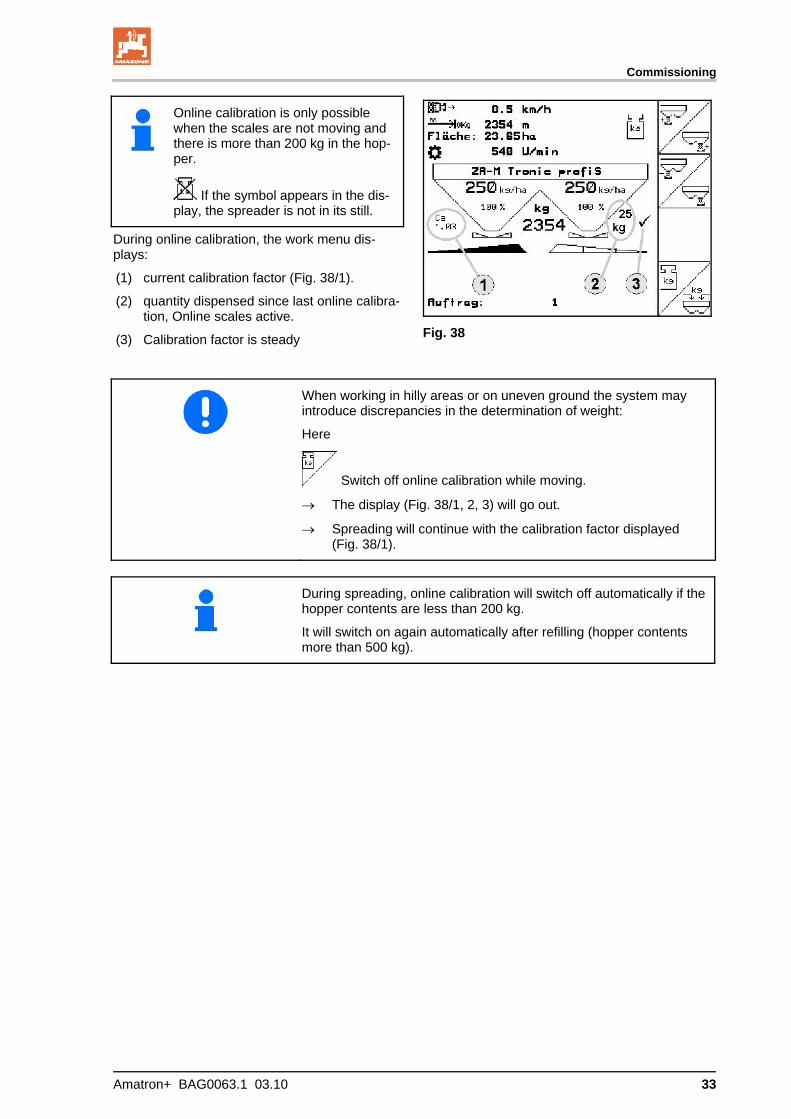
Online calibration is only possible when the scales are not moving and there is more than 200 kg in the hop-per.
If the symbol appears in the dis-play, the spreader is not in its still.
During online calibration, the work menu dis-plays:
(1) current calibration factor (Fig. 38/1).
(2) quantity dispensed since last online calibra-tion, Online scales active.
(3) Calibration factor is steady
Fig. 38
When working in hilly areas or on uneven ground the system may introduce discrepancies in the determination of weight:
Here
Switch off online calibration while moving.
The display (Fig. 38/1, 2, 3) will go out.
Spreading will continue with the calibration factor displayed (Fig. 38/1).
During spreading, online calibration will switch off automatically if the hopper contents are less than 200 kg.
It will switch on again automatically after refilling (hopper contents more than 500 kg).

Commissioning
34 Amatron+ BAG0063.1 03.10
5.5.4 Calibration of slug pellets
CAUTION
Before spreading slug pellets, be sure to check the spreading quan-tity for both outlets in turn.
To spread slug pellets, go to Machine data menu
page 3 :
1. Switch on slug pellets (Fig. 39).
Calibrate slug pellets for left outlet:
2. Add a sufficient quantity of slug pellets to the hopper.
3. Remove both spreader discs.
4. Place collection bucket under the left outlet.
5. Select Main menu to go to the Cali-brate slug pellets menu.
Fig. 39
Fig. 40
6. Check/enter the working width.
7. Check/enter the target quantity.
8. Check/enter the intended speed.
9. Take the required slider setting for the en-tered value from the settings chart.
Fig. 41
Commissioning
Amatron+ BAG0063.1 03.10 35
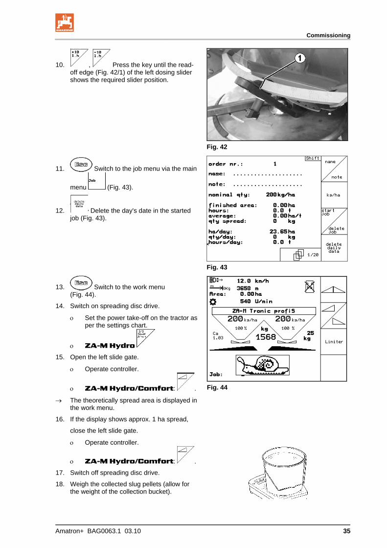
10. , Press the key until the read-off edge (Fig. 42/1) of the left dosing slider shows the required slider position.
Fig. 42
11. Switch to the job menu via the main
menu (Fig. 43).
12. Delete the day's date in the started job (Fig. 43).
Fig. 43
Fig. 44
13. Switch to the work menu (Fig. 44).
14. Switch on spreading disc drive.
Set the power take-off on the tractor asper the settings chart.
ZA-M Hydro
15. Open the left slide gate.
Operate controller.
ZA-M Hydro/Comfort: .
The theoretically spread area is displayed in the work menu.
16. If the display shows approx. 1 ha spread,
close the left slide gate.
Operate controller.
ZA-M Hydro/Comfort: .
17. Switch off spreading disc drive.
18. Weigh the collected slug pellets (allow for the weight of the collection bucket).

Commissioning
36 Amatron+ BAG0063.1 03.10
The scales must weigh accurately. Inaccuracies may cause deviations in the actual dispensed quantity.
19. Read off the theoretically dispensed quantity of pellets from the job and compare it with the weighed quantity.
20. If the calculated quantity for the job is
greater than the weighed quantity
increase the spread rate.
less than the weighed quantity
reduce the spread rate.
Calibrate slug pellets for right outlet:
Calibrate the right side in the same way as for the left outlet.
Maintain a steady speed when spreading slug pellets (as entered in the AMATRON+), because the electric setting motors do not ad-just to allow for speed when spreading pellets.
The slug in the work menu indicated that Slug pellets is selected in the Machine data menu.
Commissioning
Amatron+ BAG0063.1 03.10 37
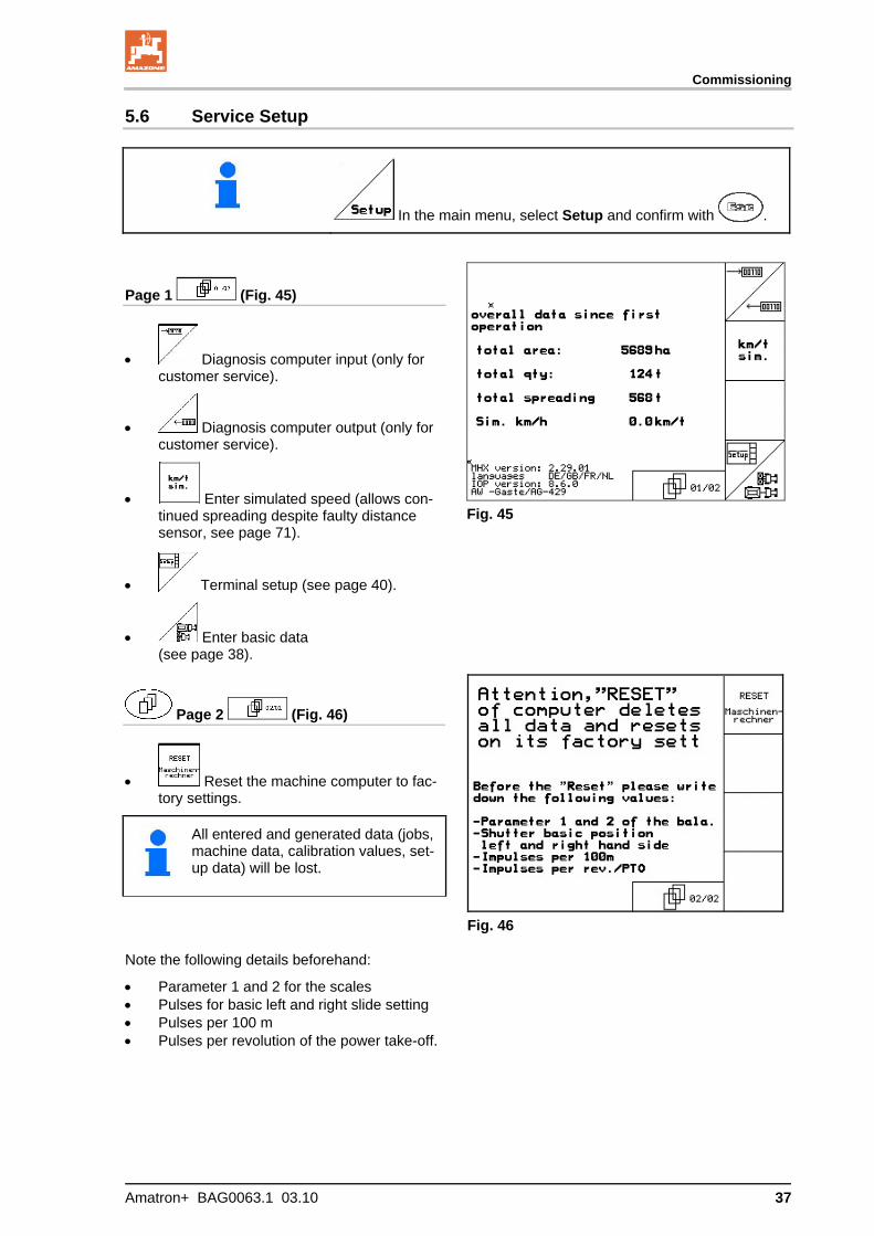
5.6 Service Setup
In the main menu, select Setup and confirm with .
Page 1 (Fig. 45)
Diagnosis computer input (only for customer service).
Diagnosis computer output (only for customer service).
Enter simulated speed (allows con-tinued spreading despite faulty distance sensor, see page 71).
Terminal setup (see page 40).
Enter basic data (see page 38).
Fig. 45
Page 2 (Fig. 46)
Reset the machine computer to fac-tory settings.
All entered and generated data (jobs, machine data, calibration values, set-up data) will be lost.
Fig. 46
Note the following details beforehand:
Parameter 1 and 2 for the scales Pulses for basic left and right slide setting Pulses per 100 m Pulses per revolution of the power take-off.
Commissioning
38 Amatron+ BAG0063.1 03.10
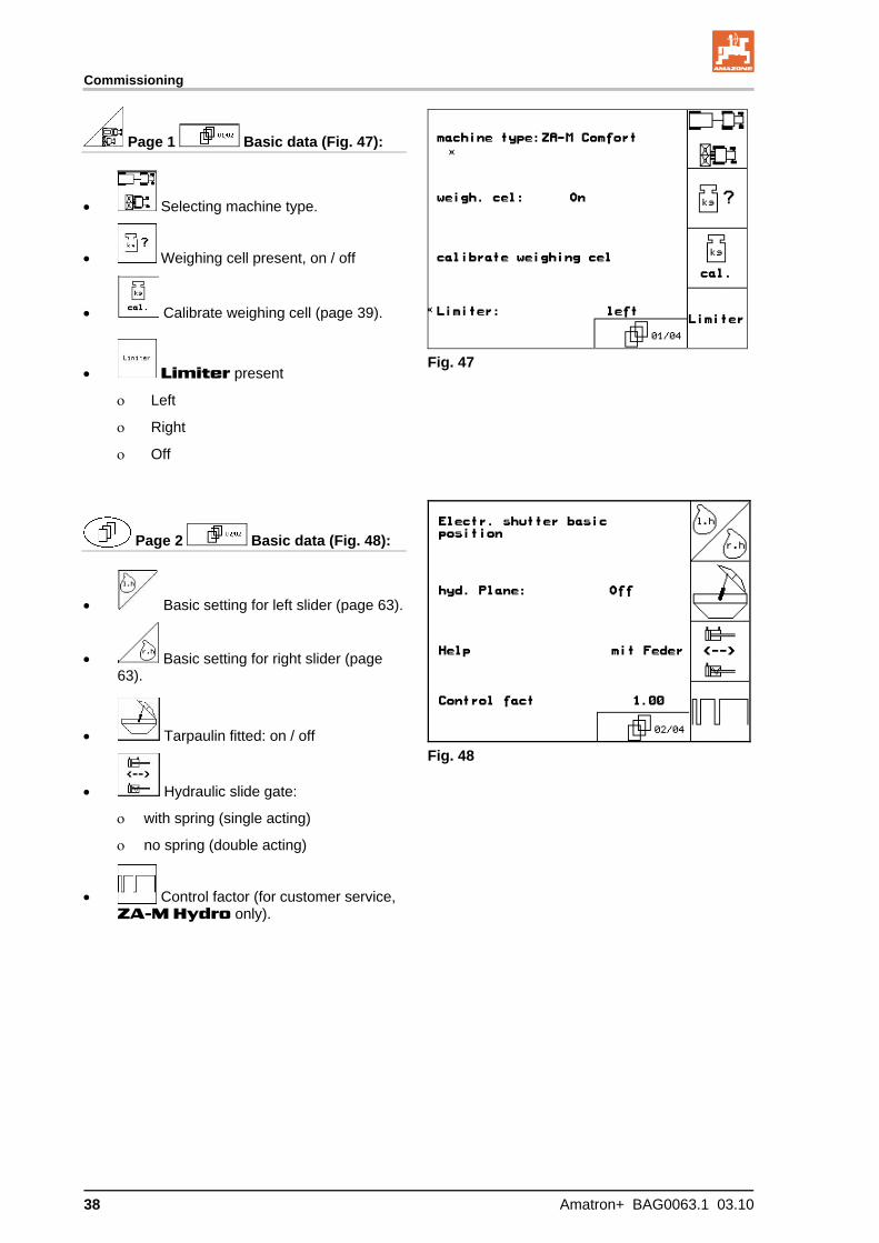
Page 1 Basic data (Fig. 47):
Selecting machine type.
Weighing cell present, on / off
Calibrate weighing cell (page 39).
Limiter present
Left
Right
Off
Fig. 47
Page 2 Basic data (Fig. 48):
Basic setting for left slider (page 63).
Basic setting for right slider (page 63).
Tarpaulin fitted: on / off
Hydraulic slide gate:
with spring (single acting)
no spring (double acting)
Control factor (for customer service, ZA-M Hydro only).
Fig. 48

Commissioning
Amatron+ BAG0063.1 03.10 39
5.6.1 Taring/calibrating weighing cell
The weighing cell is tared and calibrated at the factory. However, if there are differences be-tween the actual and the spread quantity or the hopper contents, the weighing cell needs to be recalibrated.
See Service Set-up , Basic data menu,
page one .
The weighing cell should be tared if special equipment is fitted
Fig. 49
1. Empty the fertiliser spreader completely (enter Machine data,
page one , page 19), and wait until the symbol goes out.
2. Confirm.
3. Park the tractor and attached spreader on a horizontal surface
and wait until the symbol goes out.
CAUTION
If the symbol appears in the display, the tractor is still mov-ing.
4. Press → The spreader is tared.
5. Load a precisely weighed, minimum 500 kg of fertiliser and wait
until the symbol goes out.
6. Confirm.
7. Enter the weighted amount of fertiliser in kg in the kg
AMATRON+ → The spreader is calibrated.
Check by comparing the display in the work menu with the quantity of fertiliser added.
Commissioning
40 Amatron+ BAG0063.1 03.10
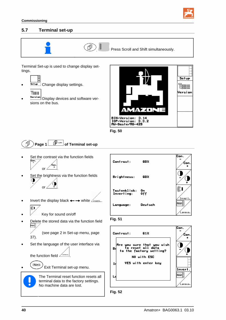
5.7 Terminal set-up
, Press Scroll and Shift simultaneously.
Terminal Set-up is used to change display set-tings.
Change display settings.
Display devices and software ver-sions on the bus.
Fig. 50
Page 1 of Terminal set-up
Set the contrast via the function fields
or .
Set the brightness via the function fields
or .
Invert the display black white .
Key for sound on/off
Delete the stored data via the function field
(see page 2 in Set-up menu, page 37).
Set the language of the user interface via
the function field .
Exit Terminal set-up menu.
The Terminal reset function resets all terminal data to the factory settings. No machine data are lost.
Fig. 51
Fig. 52

Commissioning
Amatron+ BAG0063.1 03.10 41
Page 2 of Terminal set-up
Entry of time.
Entry of date.
Entry of data transfer speed.
Fig. 53
Page 3 of Terminal set-up
Delete program:
1. , Select program.
2. Delete program.
Fig. 54
Commissioning
42 Amatron+ BAG0063.1 03.10
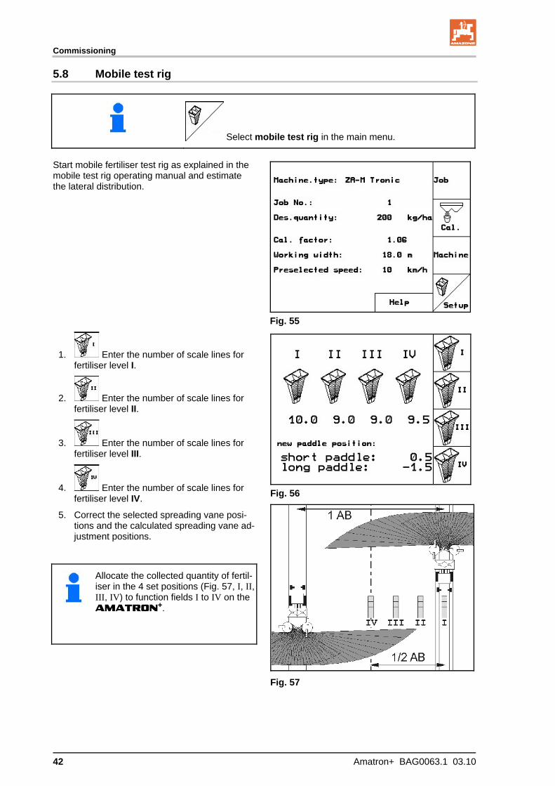
5.8 Mobile test rig
Select mobile test rig in the main menu.
Start mobile fertiliser test rig as explained in the mobile test rig operating manual and estimate the lateral distribution.
Fig. 55
1. Enter the number of scale lines for fertiliser level I.
2. Enter the number of scale lines for fertiliser level II.
3. Enter the number of scale lines for fertiliser level III.
4. Enter the number of scale lines for fertiliser level IV.
5. Correct the selected spreading vane posi-tions and the calculated spreading vane ad-justment positions.
Allocate the collected quantity of fertil-iser in the 4 set positions (Fig. 57, I, II, III, IV) to function fields I to IV on the AMATRON+.
Fig. 56
Fig. 57
Use on the field
Amatron+ BAG0063.1 03.10 43
6 Use on the field
CAUTION
During travel to the field and on public roads, the AMATRON+
should always be switched off!
Incorrect use leads to the risk of accidents!
ZA-M Profis:
Carry out an automatic fertiliser calibration when you start spreading.
Tare the spreader before you use the AMATRON+ for the first time and after fitting any special equipment (see page 39).
Before the spreader can be used, the following information must be entered:
Enter machine data (see page 19).
Load and start job (see page 25).
Calibrate fertiliser with unit at rest or enter calibration value manually (see page 27).
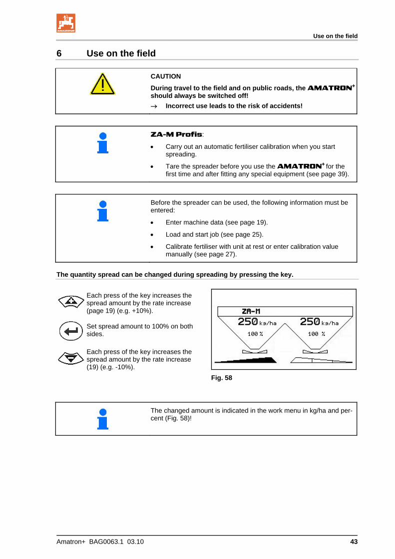
The quantity spread can be changed during spreading by pressing the key.
Each press of the key increases the spread amount by the rate increase (page 19) (e.g. +10%).
Set spread amount to 100% on both sides.
Each press of the key increases the spread amount by the rate increase (19) (e.g. -10%).
Fig. 58
The changed amount is indicated in the work menu in kg/ha and per-cent (Fig. 58)!
Use on the field
44 Amatron+ BAG0063.1 03.10
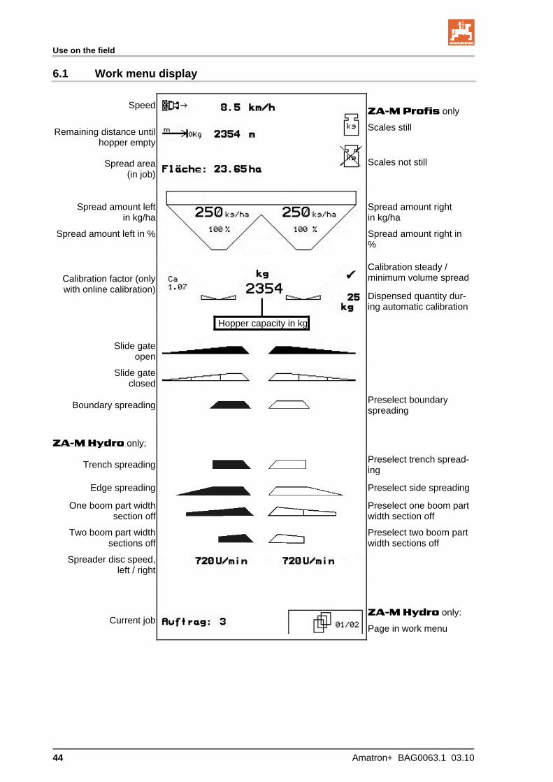
6.1 Work menu display
Speed ZA-M Profis only
Scales still Remaining distance until hopper empty
Spread area (in job)
Scales not still
Spread amount left in kg/ha
Spread amount left in %
Spread amount right in kg/ha
Spread amount right in %
Calibration steady / minimum volume spreadCalibration factor (only
with online calibration) Dispensed quantity dur-ing automatic calibration
Hopper capacity in kg
Slide gate open
Slide gate closed
Boundary spreading
Preselect boundary spreading
ZA-M Hydro only:
Trench spreading
Preselect trench spread-ing
Edge spreading
Preselect side spreading
One boom part width section off
Preselect one boom part width section off
Two boom part width sections off
Preselect two boom part width sections off
Spreader disc speed, left / right
Current job ZA-M Hydro only:
Page in work menu
Use on the field
Amatron+ BAG0063.1 03.10 45
6.2 Functions in work menu
6.2.1 Slide gate (ZA-M Comfort, Hydro only)
Both slide gates open/shut
,
Slide gate left/right, open/shut
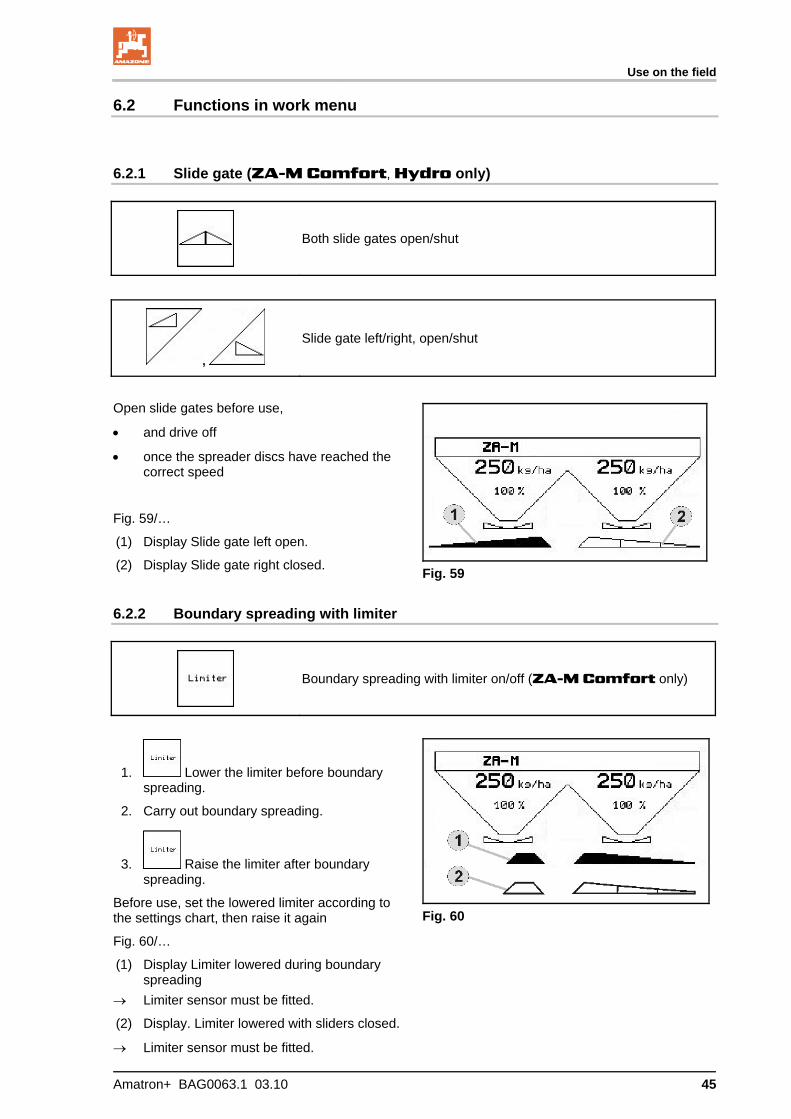
Open slide gates before use,
and drive off
once the spreader discs have reached the correct speed
Fig. 59/…
(1) Display Slide gate left open.
(2) Display Slide gate right closed.
Fig. 59
6.2.2 Boundary spreading with limiter
Boundary spreading with limiter on/off (ZA-M Comfort only)
1. Lower the limiter before boundary spreading.
2. Carry out boundary spreading.
3. Raise the limiter after boundary spreading.
Before use, set the lowered limiter according to the settings chart, then raise it again
Fig. 60/…
(1) Display Limiter lowered during boundary spreading
Limiter sensor must be fitted.
(2) Display. Limiter lowered with sliders closed.
Limiter sensor must be fitted.
Fig. 60

Use on the field
46 Amatron+ BAG0063.1 03.10
6.2.3 Changing spread quantity left/right
,
Increase spread quantity left, right.
,
Reduce spread quantity left, right.
Each press of the key changes the spread amount by the rate increase (e.g. 10%).
Enter the rate increase in the Machine data menu
Fig. 61/…
(1) Display Changed spread quantity in kg/ha and percent.
Fig. 61
6.2.4 Tarpaulin (ZA-M Comfort, Hydro only)
,
Open/close tarpaulin
Press key until tarpaulin is fully opened or closed.
Use on the field
Amatron+ BAG0063.1 03.10 47
6.2.5 Calibrating fertiliser (ZA-M Profis only)
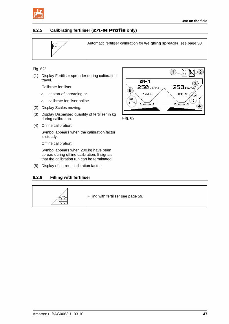
Automatic fertiliser calibration for weighing spreader, see page 30.
Fig. 62/…
(1) Display Fertiliser spreader during calibration travel.
Calibrate fertiliser
at start of spreading or
calibrate fertiliser online.
(2) Display Scales moving.
(3) Display Dispensed quantity of fertiliser in kg during calibration.
(4) Online calibration:
Symbol appears when the calibration factor is steady.
Offline calibration:
Symbol appears when 200 kg have been spread during offline calibration. It signals that the calibration run can be terminated.
(5) Display of current calibration factor
Fig. 62
6.2.6 Filling with fertiliser
Filling with fertiliser see page 59.
Use on the field
48 Amatron+ BAG0063.1 03.10
6.2.7 Switching spreading disc drive on and off (ZA-M Hydro only)
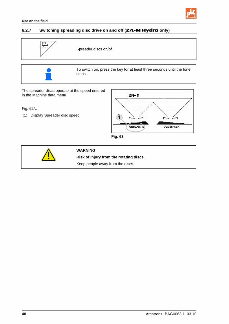
Spreader discs on/of.
To switch on, press the key for at least three seconds until the tone stops.
The spreader discs operate at the speed entered in the Machine data menu
Fig. 62/…
(1) Display Spreader disc speed
Fig. 63
WARNING
Risk of injury from the rotating discs.
Keep people away from the discs.

Use on the field
Amatron+ BAG0063.1 03.10 49
6.2.8 Boom part width sections (ZA-M Hydro only)
,
Switch on boom part width sections left, right (3 steps)
,
Switch off boom part width sections left, right (3 steps)
Fig. 64/…
(1) Display Two right-hand boom part width sections switched off.
Fig. 64
The boom width can be reduced when the discs are closed.
Use on the field
50 Amatron+ BAG0063.1 03.10
6.2.9 Boundary spreading (ZA-M Hydro only)
,
Switch on/off trench spreading left/right.
,
Switch on/off boundary spreading left/right.
,
Switch on/off side spreading left/right.
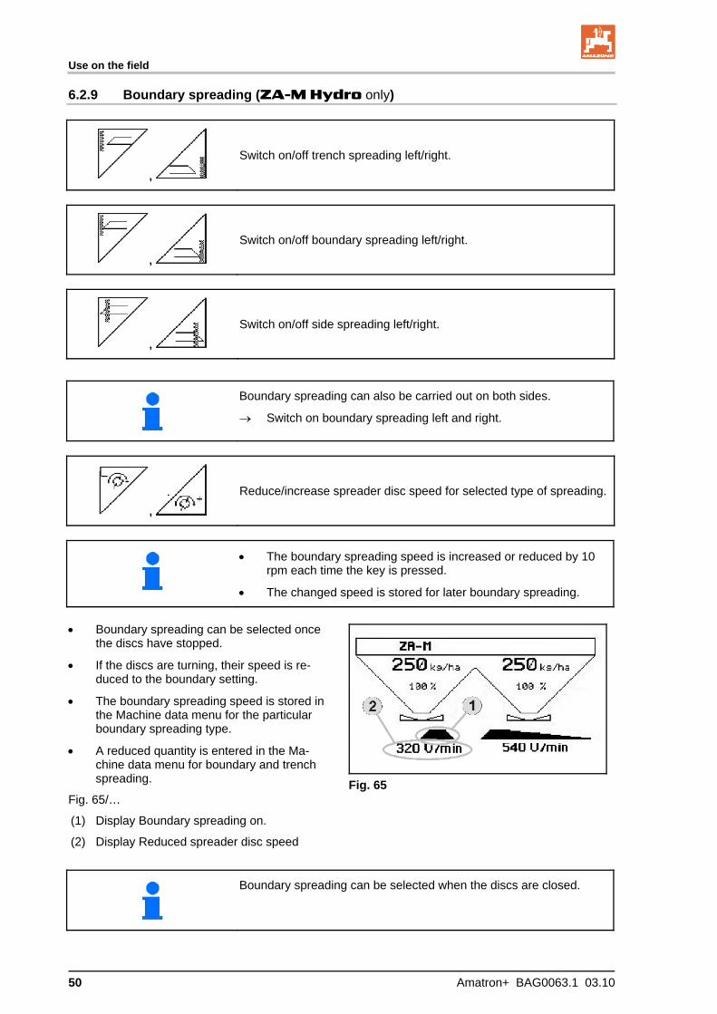
Boundary spreading can also be carried out on both sides.
Switch on boundary spreading left and right.
,
Reduce/increase spreader disc speed for selected type of spreading.
The boundary spreading speed is increased or reduced by 10 rpm each time the key is pressed.
The changed speed is stored for later boundary spreading.
Boundary spreading can be selected once
the discs have stopped.
If the discs are turning, their speed is re-duced to the boundary setting.
The boundary spreading speed is stored in the Machine data menu for the particular boundary spreading type.
A reduced quantity is entered in the Ma-chine data menu for boundary and trench spreading.
Fig. 65/…
(1) Display Boundary spreading on.
(2) Display Reduced spreader disc speed
Fig. 65
Boundary spreading can be selected when the discs are closed.

Use on the field
Amatron+ BAG0063.1 03.10 51
6.3 ZA-M Tronic
6.3.1 Procedure for use
1. Switch on the AMATRON+.
2. Select the work menu.
3. Set the power take-off speed (see setting chart).
4. Drive off and open both slide gates using tractor controllers 1 and 2.
5. In the case of the weighing spreader
start with a calibration travel
Or:
carry our online calibration (switch on in Machine data menu).
6. During spreading, the AMATRON+ shows the work menu. All the settings required for spreading should be made here.
7. These data are stored for the started job.
After use:
1. Close both slide gates using tractor controls 1 and 2.
2. Switch off power take-off.
3. Switch off the AMATRON+.
6.3.2 Work menu key layout
Page 1: Description of the function fields
See section
6.2.3 Increase spread quantity left, right
6.2.3 Reduce spread quantity left, right.
6.2.5 Automatic fertiliser calibration
6.2.6 Filling with fertiliser

Use on the field
52 Amatron+ BAG0063.1 03.10
Layout for multifunction stick

Use on the field
Amatron+ BAG0063.1 03.10 53
6.4 ZA-M Comfort
6.4.1 Procedure for use
1. Use tractor control 1 to supply the control block with hydraulic fluid.
2. Switch
on the
AMATRON+.
3. Select the work menu.
4. Set the power take-off speed (see setting chart).
5. Move off and open both slide gates
6. In the case of the weighing spreader
start with a calibration travel
Or:
carry our online calibration (switch on in Machine data menu).
7. Once boundary spreading has started:
switch on Limiter
During spreading, the AMATRON+ shows the work menu. All the settings required for spreading should be made here.
The data determined are stored for the started job.
After use:
1. Close both slide gates.
2. Switch off power take-off.
3. Use tractor controller 1 to stop the hydraulic fluid supply to the control block.
4. Switch off
AMATRON+.
Use on the field
54 Amatron+ BAG0063.1 03.10
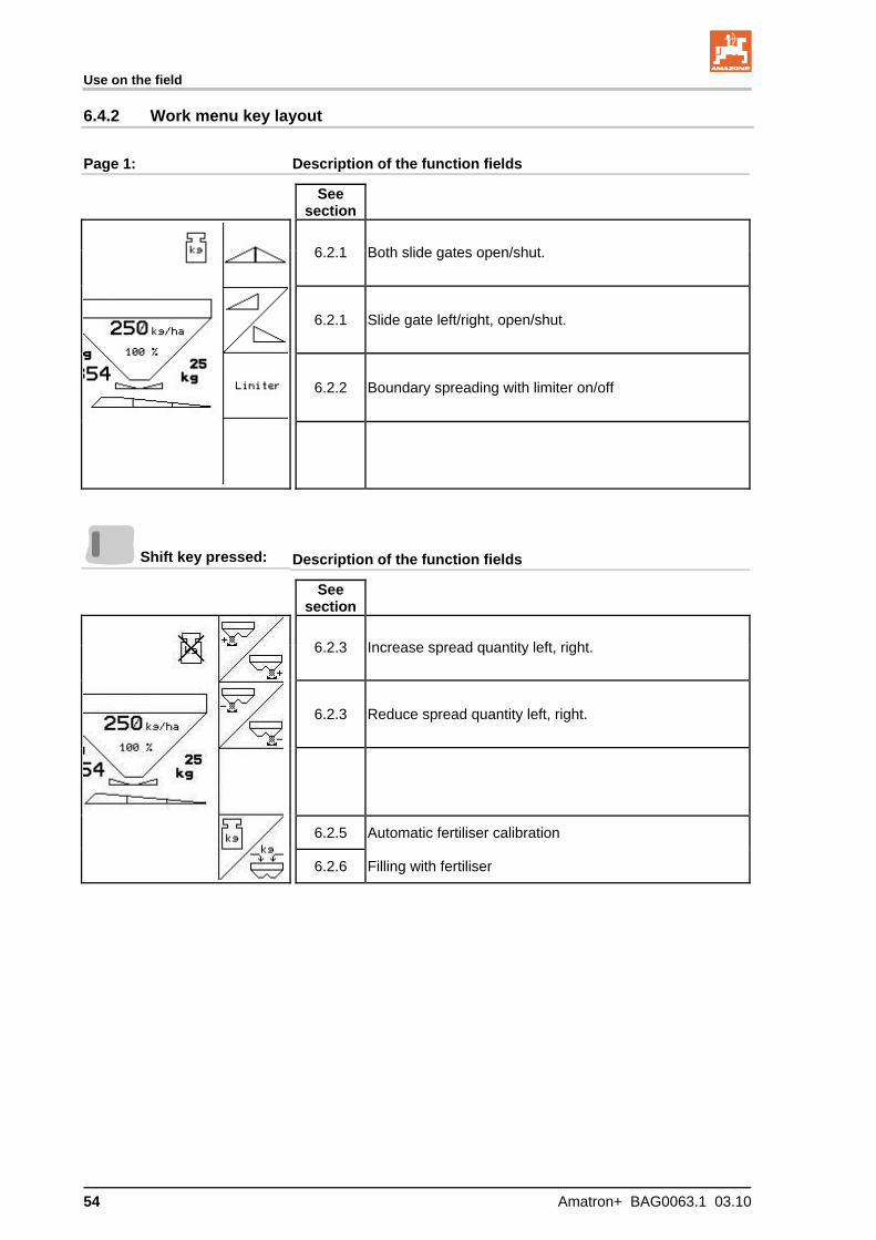
6.4.2 Work menu key layout
Page 1: Description of the function fields
See section
6.2.1 Both slide gates open/shut.
6.2.1 Slide gate left/right, open/shut.
6.2.2 Boundary spreading with limiter on/off
Shift key pressed: Description of the function fields
See section
6.2.3 Increase spread quantity left, right.
6.2.3 Reduce spread quantity left, right.
6.2.5 Automatic fertiliser calibration
6.2.6 Filling with fertiliser
Use on the field
Amatron+ BAG0063.1 03.10 55
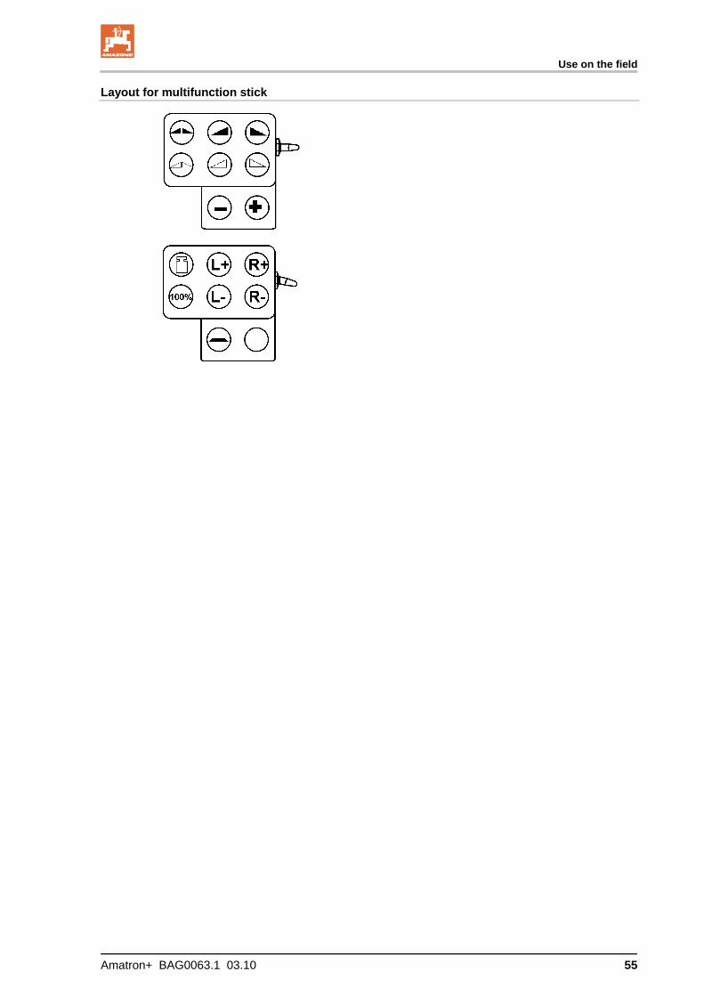
Layout for multifunction stick

Use on the field
56 Amatron+ BAG0063.1 03.10
6.5 ZA-M Hydro
6.5.1 Procedure for use
1. Use tractor control 1 to supply the control block with hydraulic fluid.
2. Switch on the AMATRON+.
3. Select the work menu.
4. Switch on spreader discs.
5 Move off and open the slide gates
6. In the case of the weighing spreader
start with a calibration travel
Or:
carry our online calibration (switch on in Machine data menu).
7. If starting with boundary, trench or side spreading:
, Select type of boundary spreading and edge of the field (left / right), and switch on.
During spreading, the AMATRON+ shows the work menu. All the settings required for spreading should be made here.
The data determined are stored for the started job.
After use:
1. Close the slide gates.
2. Switch off spreader discs.
3. Use tractor controller 1 to stop the hydraulic fluid supply to the control block.
4. Switch off the
AMATRON+.
Use on the field
Amatron+ BAG0063.1 03.10 57
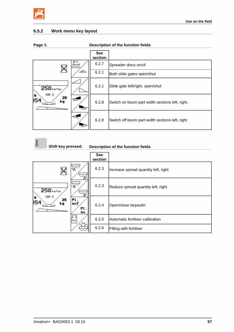
6.5.2 Work menu key layout
Page 1: Description of the function fields
See section
6.2.7 Spreader discs on/of.
6.2.1 Both slide gates open/shut
6.2.1 Slide gate left/right, open/shut
6.2.8 Switch on boom part width sections left, right.
6.2.8 Switch off boom part width sections left, right
Shift key pressed: Description of the function fields
See section
6.2.3 Increase spread quantity left, right
6.2.3 Reduce spread quantity left, right
6.2.4 Open/close tarpaulin
6.2.5 Automatic fertiliser calibration
6.2.6 Filling with fertiliser
Use on the field
58 Amatron+ BAG0063.1 03.10
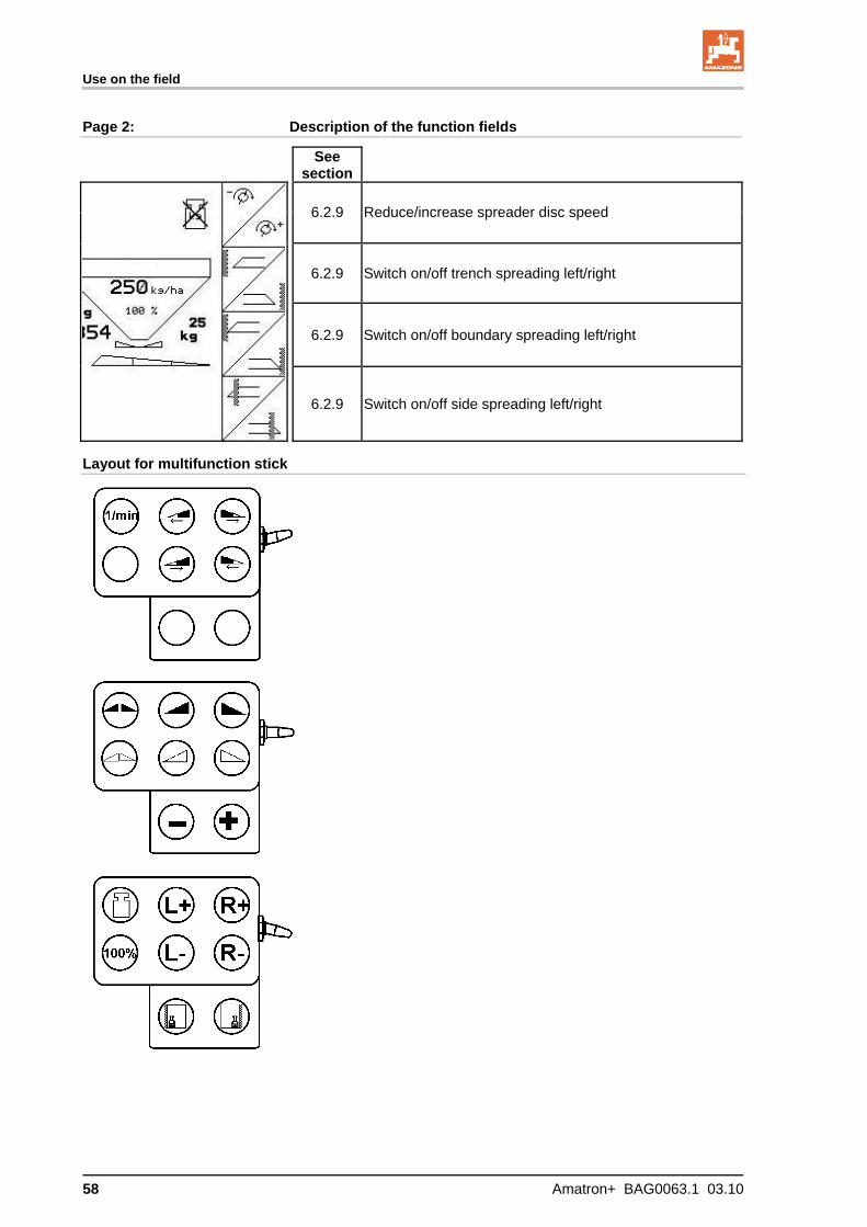
Page 2: Description of the function fields
See section
6.2.9 Reduce/increase spreader disc speed
6.2.9 Switch on/off trench spreading left/right
6.2.9 Switch on/off boundary spreading left/right
6.2.9 Switch on/off side spreading left/right
Layout for multifunction stick
Use on the field
Amatron+ BAG0063.1 03.10 59
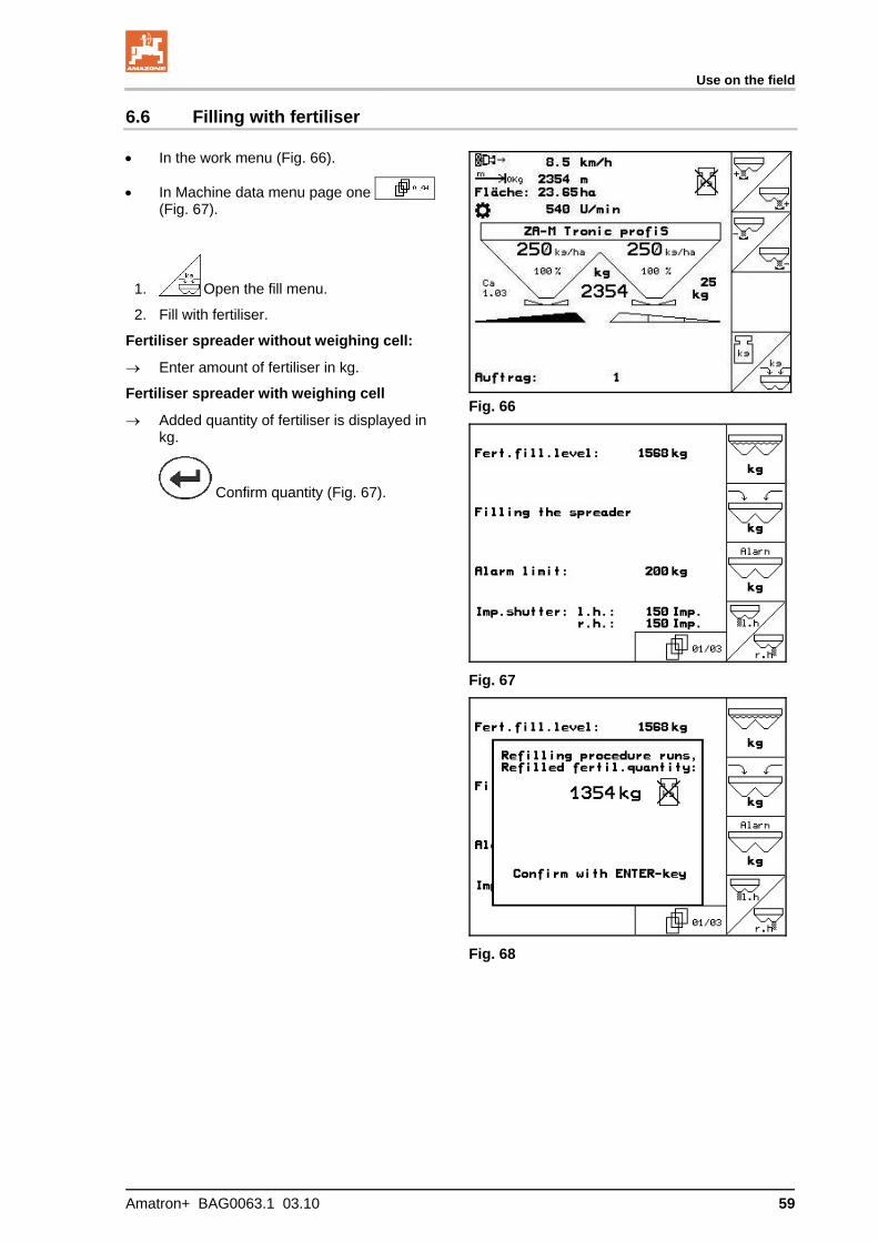
6.6 Filling with fertiliser
In the work menu (Fig. 66).
In Machine data menu page one
(Fig. 67).
1. Open the fill menu.
2. Fill with fertiliser.
Fertiliser spreader without weighing cell:
Enter amount of fertiliser in kg.
Fertiliser spreader with weighing cell
Added quantity of fertiliser is displayed in kg.
Confirm quantity (Fig. 67).
Fig. 66
Fig. 67
Fig. 68
Use on the field
60 Amatron+ BAG0063.1 03.10
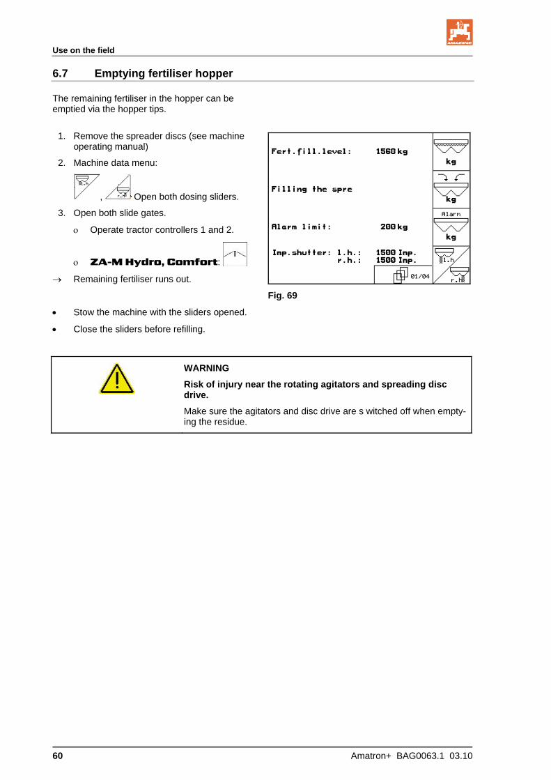
6.7 Emptying fertiliser hopper
The remaining fertiliser in the hopper can be emptied via the hopper tips.
1. Remove the spreader discs (see machine
operating manual)
2. Machine data menu:
, Open both dosing sliders.
3. Open both slide gates.
Operate tractor controllers 1 and 2.
ZA-M Hydro, Comfort:
Remaining fertiliser runs out.
Stow the machine with the sliders opened.
Close the sliders before refilling.
Fig. 69
WARNING
Risk of injury near the rotating agitators and spreading disc drive.
Make sure the agitators and disc drive are s witched off when empty-ing the residue.
Multifunction stick
Amatron+ BAG0063.1 03.10 61
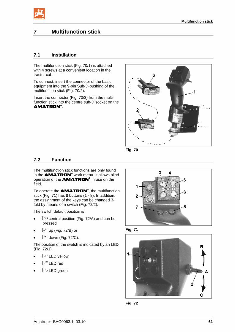
7 Multifunction stick
7.1 Installation
The multifunction stick (Fig. 70/1) is attached with 4 screws at a convenient location in the tractor cab.
To connect, insert the connector of the basic equipment into the 9-pin Sub-D-bushing of the multifunction stick (Fig. 70/2).
Insert the connector (Fig. 70/3) from the multi-function stick into the centre sub-D socket on the AMATRON+.
Fig. 70
7.2 Function
The multifunction stick functions are only found in the AMATRON+ work menu. It allows blind operation of the AMATRON+ in use on the field.
To operate the AMATRON+, the multifunction stick (Fig. 71) has 8 buttons (1 - 8). In addition, the assignment of the keys can be changed 3-fold by means of a switch (Fig. 72/2).
The switch default position is
central position (Fig. 72/A) and can be pressed
up (Fig. 72/B) or
down (Fig. 72/C).
The position of the switch is indicated by an LED (Fig. 72/1).
LED yellow
LED red
LED green
Fig. 71
Fig. 72
Multifunction stick
62 Amatron+ BAG0063.1 03.10
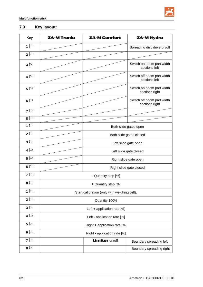
7.3 Key layout:
Key ZA-M Tronic ZA-M Comfort ZA-M Hydro
1 Spreading disc drive on/off
2
3 Switch on boom part width sections left
4 Switch off boom part width sections left
5 Switch on boom part width sections right
6 Switch off boom part width sections right
7
8
1 Both slide gates open
2 Both slide gates closed
3 Left slide gate open
4 Left slide gate closed
5 Right slide gate open
6 Right slide gate closed
7 - Quantity step [%]
8 + Quantity step [%]
1 Start calibration (only with weighing cell).
2 Quantity 100%
3 Left + application rate [%]
4 Left - application rate [%]
5 Right + application rate [%]
6 Right - application rate [%]
7 Limiter on/off Boundary spreading left
8 Boundary spreading right

Maintenance and cleaning
Amatron+ BAG0063.1 03.10 63
8 Maintenance and cleaning
WARNING
Perform maintenance and cleaning only with the spreader discs and agitator shaft drive switched off.
8.1 Cleaning
DANGER
Do not reach into the outlet opening while operating the sliders! Risk of crushing!
To clean the fertiliser spreader, you must have the slide gates and the
electric dosing sliders open so the water and residual fertiliser can drain.
Opening/closing dosing sliders (see Machine data menu, page 19).
Opening/closing slide gates (see ZA-M Hydro / ZA-M Comfort work menu).
8.2 Basic slide setting
The amount of cross-sectional clearance of the electric dosing sliders is set at the factory (Fig. 73).
If, despite identical slider positions, you find that the two hopper tips are not emptying uniformly, check the basic setting of the sliders.
Fig. 73
Specify the basic setting for both rate slides us-ing the Set-up menu:
1. Select basic data.
Page two (Fig. 74)
2. Set left slider position.
3. Set right slider position.
Fig. 74

Maintenance and cleaning
64 Amatron+ BAG0063.1 03.10
4. Close the outlet fully (0 pulses).
5. Open the outlet to 1500 pulses.
DANGER
Risk of injury near dosing sliders
when key pressed, , ,
, , because the sliders close before the selected setting is applied.
Keep fingers and gauges away from the opening.
6. Insert the setting gauge (Fig. 76/1) (Option, order no.: 915018) slightly into the opening.
The gauge cannot be inserted through the opening:
Increase the current offset by 5 pulses until the gauge fits exactly in the opening (Fig. 77).
Too much gauge clearance:
Reduce the current offset by 5 pulses until the gauge fits exactly in the open-ing (Fig. 77).
7. Confirm the position with the input key.
Fig. 75
Fig. 76
Fig. 77
The setting motor pulses (Fig. 78/1) can be displayed in the work menu.
Fig. 78
Malfunction
Amatron+ BAG0063.1 03.10 65
9 Malfunction
9.1 Alarm
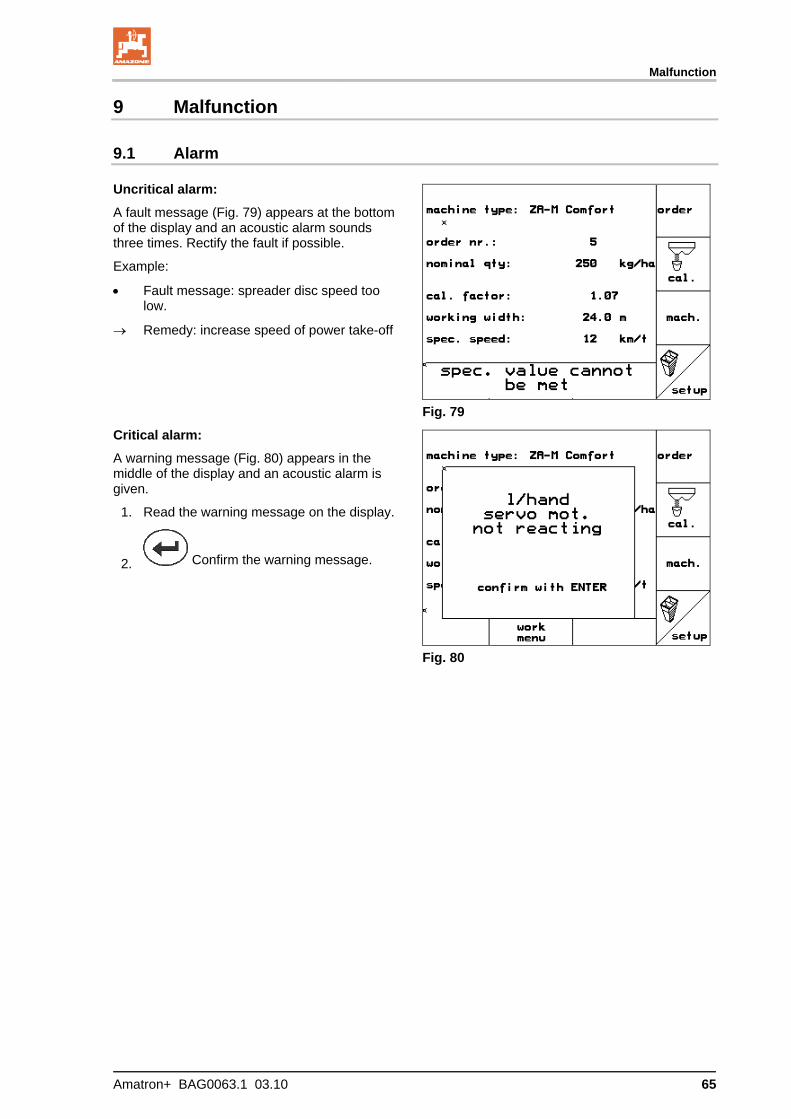
Uncritical alarm:
A fault message (Fig. 79) appears at the bottom of the display and an acoustic alarm sounds three times. Rectify the fault if possible.
Example:
Fault message: spreader disc speed too low.
Remedy: increase speed of power take-off
Fig. 79
Critical alarm:
A warning message (Fig. 80) appears in the middle of the display and an acoustic alarm is given.
1. Read the warning message on the display.
2. Confirm the warning message.
Fig. 80

Malfunction
66 Amatron+ BAG0063.1 03.10
9.2 Error messages and remedies
Error messages Cause / description of fault Fault remedy
1 Setpoint value cannot be main-tained
Application rate cannot be maintained with the set parameters at current ground travel speed.
Reduce ground travel speed
Reduce setpoint value
2 Input of setpoint in "kg/ha" missing. Enter setpoint
3 Working width missing
Input of the working width in "m" missing. Enter working width
4 Setting motor left does not respond
The left setting motor does not move when activated
Replace setting motor Carry out diagnostics
on setting motor
5 Setting motor right does not respond
The right setting motor does not move when activated
Replace setting motor Carry out diagnostics
on setting motor
6 PTO speed de-viation
The PTO speed is outside the set limits for the stored setpoint. Adjust PTO speed
7 Filling level too low
Filling level in hopper is below filling level set for alarm limit.
Replenish spreader Adjust filling level
alarm limit
8 Spreader disc speed too low
Speed of spreader discs is below set rated speed.
Adjust spreader disc speed
9 Dosing chamber filling level too low
Filling level in dosing chamber of ZG-B PreciS / Ultra Hydro too low.
Check fertiliser filling level in hopper
Check sensors in input diagnosis
10 Dosing chamber filling level too high
Filling level in dosing chamber of ZG-B PreciS / Ultra Hydro too high.
Was fertiliser spread on one side? If so, this may result in "piling" in the dosing chamber.
Check sensors in input diagnosis
11 Value on scales fluctuates
Scales do not supply a steady signal Wait until scales are
steady again (display goes out)
12 Please press "Shift" and "Scroll"
The key "Call up terminal setup" was pressed.
Press key combination indicated
13 Centre position not reached
Centre position sensor of Trail Tron (drawbar) transmits no signal, although the on-board computer expects a signal.
This is a safety check for the centre position sensor.
Move drawbar to cen-tre position.
14
Min. kg have not yet been spread! Abort calibrati-on?
During "Calibration in the field", minimum quantity has not yet been spread, but key "Terminate calibration" was pressed.
Press key "ESC" Start "Calibration of
the move" again and wait until the "tick" ap-pears before finishing.
15
Hopper filling level too low, minimum hopper content 500 kg
Key "Start calibration" / "Start online cali-bration" was pressed, but filling level is still below the specified value.
Replenish spreader
Malfunction
Amatron+ BAG0063.1 03.10 67
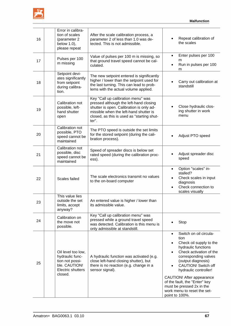
16
Error in calibra-tion of scales (parameter 2 below 1.0), please repeat
After the scale calibration process, a parameter 2 of less than 1.0 was de-tected. This is not admissible.
Repeat calibration of the scales
17 Pulses per 100 m missing
Value of pulses per 100 m is missing, so that ground travel speed cannot be cal-culated.
Enter pulses per 100 m
Run in pulses per 100 m
18
Setpoint devi-ates significantly from setpoint during calibra-tion.
The new setpoint entered is significantly higher / lower than the setpoint used for the last turning. This can lead to prob-lems with the actual volume applied.
Carry out calibration at standstill
19
Calibration not possible, left-hand shutter open
Key "Call up calibration menu" was pressed although the left-hand closing shutter is open. Calibration is only ad-missible when the left-hand shutter is closed, as this is used as "starting shut-ter".
Close hydraulic clos-ing shutter in work menu
20
Calibration not possible, PTO speed cannot be maintained
The PTO speed is outside the set limits for the stored setpoint (during the cali-bration process).
Adjust PTO speed
21
Calibration not possible, disc speed cannot be maintained
Speed of spreader discs is below set rated speed (during the calibration proc-ess).
Adjust spreader disc speed
22 Scales failed The scale electronics transmit no values to the on-board computer
Option "scales" in-stalled?
Check scales in input diagnosis
Check connection to scales visually
23 This value lies outside the set limits, accept anyway?
An entered value is higher / lower than its admissible value.
24 Calibration on the move not possible.
Key "Call up calibration menu" was pressed while a ground travel speed was detected. Calibration is this menu is only admissible at standstill.
Stop
25
Oil level too low, hydraulic func-tion not possi-ble. CAUTION! Electric shutters closed.
A hydraulic function was activated (e.g. close left-hand closing shutter), but there is no reaction (e.g. change in a sensor signal).
Switch on oil circula-tion
Check oil supply to the hydraulic functions
Check activation of the corresponding valves (output diagnosis)
CAUTION! Switch off hydraulic controller!
CAUTION! After appearance of the fault, the "Enter" key must be pressed 2x in the work menu to reset the set-point to 100%.
Malfunction
68 Amatron+ BAG0063.1 03.10
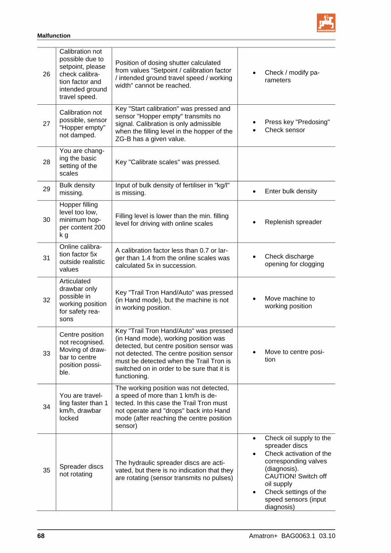
26
Calibration not possible due to setpoint, please check calibra-tion factor and intended ground travel speed.
Position of dosing shutter calculated from values "Setpoint / calibration factor / intended ground travel speed / working width" cannot be reached.
Check / modify pa-rameters
27
Calibration not possible, sensor "Hopper empty" not damped.
Key "Start calibration" was pressed and sensor "Hopper empty" transmits no signal. Calibration is only admissible when the filling level in the hopper of the ZG-B has a given value.
Press key "Predosing" Check sensor
28
You are chang-ing the basic setting of the scales
Key "Calibrate scales" was pressed.
29 Bulk density missing.
Input of bulk density of fertiliser in "kg/l" is missing. Enter bulk density
30
Hopper filling level too low, minimum hop-per content 200 k g
Filling level is lower than the min. filling level for driving with online scales Replenish spreader
31
Online calibra-tion factor 5x outside realistic values
A calibration factor less than 0.7 or lar-ger than 1.4 from the online scales was calculated 5x in succession.
Check discharge opening for clogging
32
Articulated drawbar only possible in working position for safety rea-sons
Key "Trail Tron Hand/Auto" was pressed (in Hand mode), but the machine is not in working position.
Move machine to working position
33
Centre position not recognised. Moving of draw-bar to centre position possi-ble.
Key "Trail Tron Hand/Auto" was pressed (in Hand mode), working position was detected, but centre position sensor was not detected. The centre position sensor must be detected when the Trail Tron is switched on in order to be sure that it is functioning.
Move to centre posi-tion
34
You are travel-ling faster than 1 km/h, drawbar locked
The working position was not detected, a speed of more than 1 km/h is de-tected. In this case the Trail Tron must not operate and "drops" back into Hand mode (after reaching the centre position sensor)
35 Spreader discs not rotating
The hydraulic spreader discs are acti-vated, but there is no indication that they are rotating (sensor transmits no pulses)
Check oil supply to the spreader discs
Check activation of the corresponding valves (diagnosis). CAUTION! Switch off oil supply
Check settings of the speed sensors (input diagnosis)

Malfunction
Amatron+ BAG0063.1 03.10 69
36 Cleaning hood sensor failed
Sensor on cleaning hood of ZG-B Ultra Hydro transmits no signal.
Check sensor (input diagnosis)
Replace sensor
37 Cleaning hood open
The system has detected that the clean-ing hood is open. This condition is not admissible in working position.
Close cleaning hood
38 Spreader disc control machine computer failed
Machine computer of the spreader disc control of the ZG-B Ultra hydro transmits no signals
Check connection be-tween base machine computer and spreader disc control machine computer visually
Check set machine type
Replace spreader disc control machine com-puter
39 Do you want to delete this or-der?
Key "Delete order" was pressed.
40
CAUTION! You are changing the basic setting of the machine
The key "Call up setup" was pressed. Enter key = Do not call
up setup ESC = Call up setup
41
Do you really want to reset all data to the works setting?
The key "Reset" was pressed.
ESC = Do not carry out reset
Enter key = Carry out reset
42
Calibration not possible, sensor "Hopper full" not damped.
Key "Start calibration" was pressed and sensor "Hopper full" transmits no signal. Calibration is only admissible when the filling level in the hopper of the ZG-B has a given value.
Press key "Predosing" Check sensor

Malfunction
70 Amatron+ BAG0063.1 03.10
9.3 Failure of setting motors
If faults occur in the AMATRON+ or electric setting motors and cannot be rectified immedi-ately, you can still continue working:
after extending the setting motors,
after modifying the setting lever.
The rate as per setting chart is then determined by means of the setting lever (Fig. 81/1).
1. Close the hydraulic slider.
2. Release the thumb screw (Fig. 81/2).
3. Look for the required slider position on the scale (Fig. 81/3).
4. Adjust the read-off edge (Fig. 81/4) of the setting lever pointer (Fig. 81/5) so that it corresponds to the scale value.
5. Insert washers behind the setting lever.
6. Retighten the thumb screw (Fig. 81/2).
Fig. 81
Fig. 82
Extending the setting motors and modifying the setting lever:
1. Remove the two securing clips (Fig. 82/3) with pliers /.
2. Withdraw the two hinge pins (Fig. 82/4).
3. Remove the setting motor (Fig. 82/1) from the console.
4. Raise the setting motor /and detach the pushrod (Fig. 82/2) from the plug-in connection of the dosing slider.
5. Then again secure the setting motor with detached pushrod in the engine console in accordance with regulations.

Malfunction
Amatron+ BAG0063.1 03.10 71
Secure the detached pushrod (Fig. 82/2) against swivelling into the working area of the hydraulic cylinder.
6. Set up the clamping device (Fig. 83/1) for setting levers (Fig. 83/2) as follows:
6.1 Unscrew the wing nut (Fig. 83/3).
6.2 Remove the screw and reposition the two washers (Fig. 83/4) from the back (Fig. 83/5) to the front (Fig. 83/6).
Fig. 83
9.4 Distance sensor (pulses/100 m failure)
Entering a simulated speed in the Service Set-up menu allows you to continue spreading if the sensor fails.
To do so:
1. Remove the signal cable from the tractor basic equipment.
2. Enter a simulated speed.
3. Maintain the simulated speed as you con-tinue spreading.
As soon as pulses are registered by the distance sensor, the computer switches to the actual speed of the distance sensor.
Fig. 84

H. DREYER GmbH & Co. KG Postfach 51
D-49202 Hasbergen-Gaste Germany
Tel.: + 49 (0) 5405 501-0 Fax: + 49 (0) 5405 501-234 e-mail: [email protected] http:// www.amazone.de
Plants: D-27794 Hude D-04249 Leipzig F-57602 Forbach Branches in England and France
Manufacturers of mineral fertiliser spreaders, field sprayers, seed drills, soil cultivation machines, mul-tipurpose warehouses and communal units


