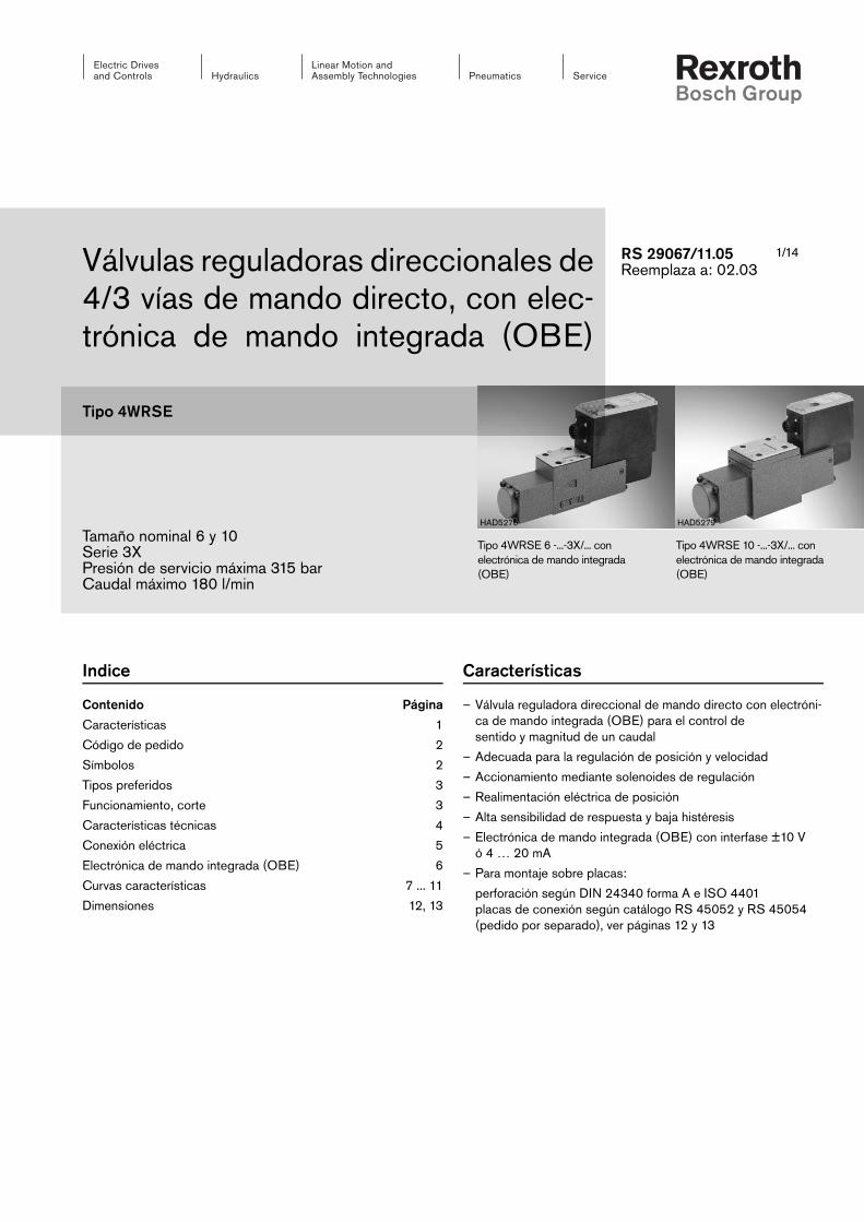
1/14Válvulas reguladoras direccionales de 4/3 vías de mando directo, con elec-trónica de mando integrada (OBE)
Tipo 4WRSE
Tamaño nominal 6 y 10Serie 3XPresión de servicio máxima 315 barCaudal máximo 180 l/min
RS 29067/11.05Reemplaza a: 02.03
Tipo 4WRSE 10 -...-3X/... con electrónica de mando integrada (OBE)
Tipo 4WRSE 6 -...-3X/... con electrónica de mando integrada (OBE)
HAD5279HAD5276
Indice
Contenido Página
Características 1
Código de pedido 2
Símbolos 2
Tipos preferidos 3
Funcionamiento, corte 3
Características técnicas 4
Conexión eléctrica 5
Electrónica de mando integrada (OBE) 6
Curvas características 7 ... 11
Dimensiones 12, 13
Características
– Válvula reguladora direccional de mando directo con electróni-ca de mando integrada (OBE) para el control desentido y magnitud de un caudal
– Adecuada para la regulación de posición y velocidad
– Accionamiento mediante solenoides de regulación
– Realimentación eléctrica de posición
– Alta sensibilidad de respuesta y baja histéresis
– Electrónica de mando integrada (OBE) con interfase ±10 V ó 4 … 20 mA
– Para montaje sobre placas:
perforación según DIN 24340 forma A e ISO 4401placas de conexión según catálogo RS 45052 y RS 45054(pedido por separado), ver páginas 12 y 13
2/14 Bosch Rexroth AG Hydraulics Tipo 4WRSE RS 29067/11.05
4WRS E 3X G24 K0 V *
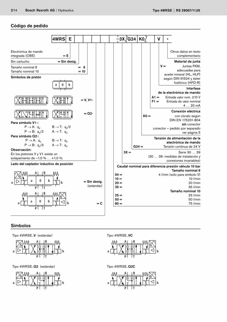
Código de pedido
Electrónica de mandointegrada (OBE) = E
Sin cartucho = Sin desig.
Tamaño nominal 6 = 6Tamaño nominal 10 = 10
Símbolos de pistón
a 0 b
Para símbolo V1-: P → A: qV B → T: qV/2 P → B: qV/2 A → T: qVPara símbolo Q2-: P → A: qV B → T: qV P → B: qV/3 A → T: qVObservación:En los pistones V y V1 existe un solapamiento de –1,0 % … +1,0 %.
= V, V1-
= Q2-
Lado del captador inductivo de posición
a b0
A
P
a
B
T
b
G
a b0 ba
P
A
T
BG
= Sin desig. (estándar)
= C
Otros datos en texto complementario
Material de juntaV = Juntas FKM, adecuadas para
aceite mineral (HL, HLP) según DIN 51524 y éster
fosfórico (HFD-R)
Interfasede la electrónica de mando
A1 = Entrada valor nom. ±10 VF1 = Entrada de valor nominal
4 … 20 mA
Conexión eléctricaK0 = con zócalo según DIN EN 175201-804
sin conector conector – pedido por separado
ver página 5
Tensión de alimentación de la electrónica de mando
G24 = Tensión continua de 24 V
3X = Serie 30 … 39(30 … 39: medidas de instalación y
conexiones invariables)
Caudal nominal para diferencia presión válvula 10 bar Tamaño nominal 6
04 = 4 l/min (sólo para símbolo V)10 = 10 l/min20 = 20 l/min35 = 35 l/min
Tamaño nominal 1025 = 25 l/min50 = 50 l/min80 = 75 l/min
Símbolos
Tipo 4WRSE..V (estándar) Tipo 4WRSE..VC
A
P
a
B
T
b
G
ba
P
A
T
BG
Tipo 4WRSE..Q2 (estándar) Tipo 4WRSE..Q2C
G
a
BA
P T
b
A
P
a
B
T
b
G
TA TBPA B
"a" "b"
9 87
5 3 1 2 4 6
Hydraulics Bosch Rexroth AGRS 29067/11.05 tipo 4WRSE 3/14
Tipos preferidos
TN6
Tipo Nro. de referencia
4WRSE 6 V04-3X/G24K0/A1V R900938307
4WRSE 6 V1-10-3X/G24K0/A1V R900909078
4WRSE 6 V1-20-3X/G24K0/A1V R900906155
4WRSE 6 V1-35-3X/G24K0/A1V R900904794
4WRSE 6 V10-3X/G24K0/A1V R900558830
4WRSE 6 V20-3X/G24K0/A1V R900576060
4WRSE 6 V35-3X/G24K0/A1V R900579447
TN10
Tipo Nro. de referencia
4WRSE 10 Q2-50-3X/G24K0/A1V R900916872
4WRSE 10 V1-80-3X/G24K0/A1V R900556812
4WRSE 10 V1-25-3X/G24K0/A1V R900922997
4WRSE 10 V1-50-3X/G24K0/A1V R900579140
4WRSE 10 V25-3X/G24K0/A1V R900579637
4WRSE 10 V50-3X/G24K0/A1V R900579943
4WRSE 10 V80-3X/G24K0/A1V R900579286
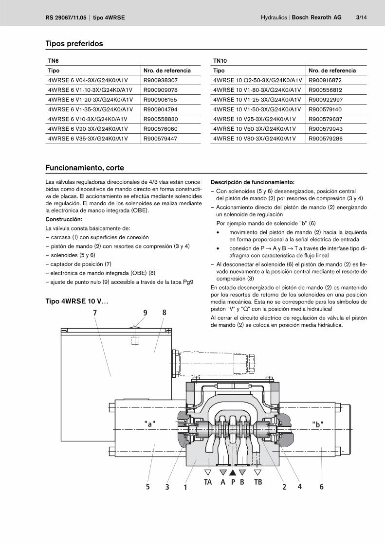
Las válvulas reguladoras direccionales de 4/3 vías están conce-bidas como dispositivos de mando directo en forma constructi-va de placas. El accionamiento se efectúa mediante solenoides de regulación. El mando de los solenoides se realiza mediante la electrónica de mando integrada (OBE).
Construcción:
La válvula consta básicamente de:
– carcasa (1) con superficies de conexión
– pistón de mando (2) con resortes de compresión (3 y 4)
– solenoides (5 y 6)
– captador de posición (7)
– electrónica de mando integrada (OBE) (8)
– ajuste de punto nulo (9) accesible a través de la tapa Pg9
Descripción de funcionamiento:
– Con solenoides (5 y 6) desenergizados, posición central del pistón de mando (2) por resortes de compresión (3 y 4)
– Accionamiento directo del pistón de mando (2) energizando un solenoide de regulación
Por ejemplo mando de solenoide "b" (6)
• movimiento del pistón de mando (2) hacia la izquierda en forma proporcional a la señal eléctrica de entrada
• conexión de P → A y B → T a través de interfase tipo di-afragma con característica de flujo lineal
– Al desconectar el solenoide (6) el pistón de mando (2) es lle-vado nuevamente a la posición central mediante el resorte de compresión (3)
En estado desenergizado el pistón de mando (2) es mantenido por los resortes de retorno de los solenoides en una posición media mecánica. Esta no se corresponde para los símbolos de pistón “V“ y “Q“ con la posición media hidráulica!
Al cerrar el circuito eléctrico de regulación de válvula el pistón de mando (2) se coloca en posición media hidráulica.
Funcionamiento, corte
Tipo 4WRSE 10 V…
4/14 Bosch Rexroth AG Hydraulics Tipo 4WRSE RS 29067/11.05
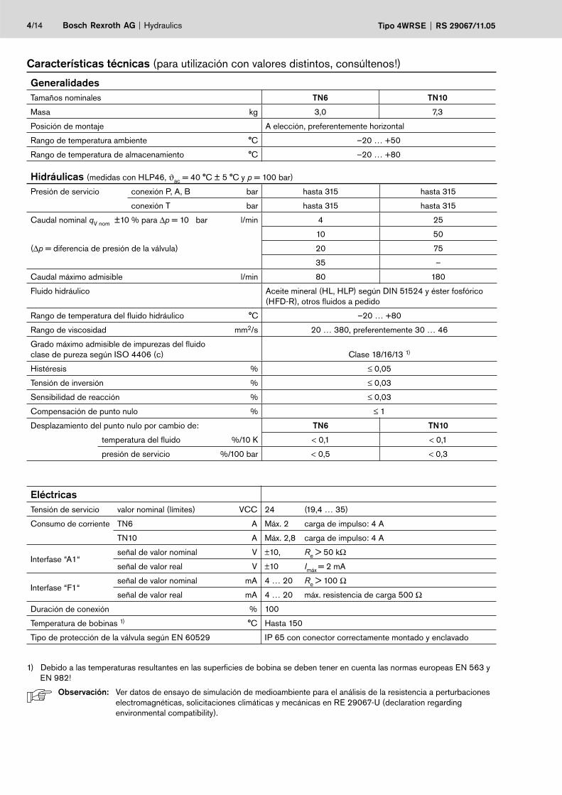
Características técnicas (para utilización con valores distintos, consúltenos!)
GeneralidadesTamaños nominales TN6 TN10
Masa kg 3,0 7,3
Posición de montaje A elección, preferentemente horizontal
Rango de temperatura ambiente °C –20 … +50
Rango de temperatura de almacenamiento °C –20 … +80
Hidráulicas (medidas con HLP46, ϑac = 40 °C ± 5 °C y p = 100 bar)
Presión de servicio conexión P, A, B bar hasta 315 hasta 315
conexión T bar hasta 315 hasta 315
Caudal nominal qV nom ±10 % para ∆p = 10 bar l/min 4 25
10 50
(∆p = diferencia de presión de la válvula) 20 75
35 –
Caudal máximo admisible l/min 80 180
Fluido hidráulico Aceite mineral (HL, HLP) según DIN 51524 y éster fosfórico (HFD-R), otros fluidos a pedido
Rango de temperatura del fluido hidráulico °C –20 … +80
Rango de viscosidad mm2/s 20 … 380, preferentemente 30 … 46
Grado máximo admisible de impurezas del fluido clase de pureza según ISO 4406 (c) Clase 18/16/13 1)
Histéresis % ≤ 0,05
Tensión de inversión % ≤ 0,03
Sensibilidad de reacción % ≤ 0,03
Compensación de punto nulo % ≤ 1
Desplazamiento del punto nulo por cambio de: TN6 TN10
temperatura del fluido %/10 K < 0,1 < 0,1
presión de servicio %/100 bar < 0,5 < 0,3
EléctricasTensión de servicio valor nominal (límites) VCC 24 (19,4 … 35)
Consumo de corriente TN6 A Máx. 2 carga de impulso: 4 A
TN10 A Máx. 2,8 carga de impulso: 4 A
Interfase “A1“señal de valor nominal V ±10, Re > 50 kΩ
señal de valor real V ±10 Imáx = 2 mA
Interfase “F1“señal de valor nominal mA 4 … 20 Re > 100 Ω
señal de valor real mA 4 … 20 máx. resistencia de carga 500 Ω
Duración de conexión % 100
Temperatura de bobinas 1) °C Hasta 150
Tipo de protección de la válvula según EN 60529 IP 65 con conector correctamente montado y enclavado
1) Debido a las temperaturas resultantes en las superficies de bobina se deben tener en cuenta las normas europeas EN 563 y EN 982!
Observación: Ver datos de ensayo de simulación de medioambiente para el análisis de la resistencia a perturbaciones electromagnéticas, solicitaciones climáticas y mecánicas en RE 29067-U (declaration regarding environmental compatibility).
Hydraulics Bosch Rexroth AGRS 29067/11.05 tipo 4WRSE 5/14
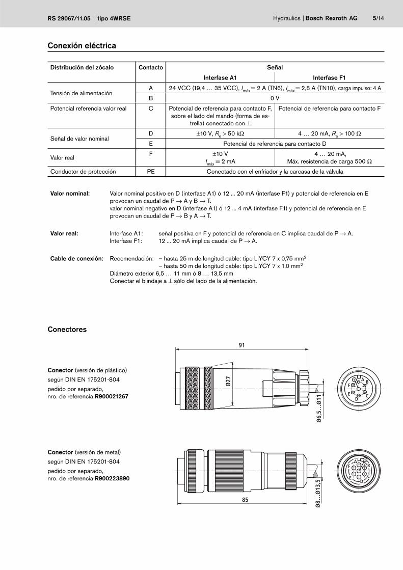
Conexión eléctrica
Conector (versión de plástico)
según DIN EN 175201-804
pedido por separado, nro. de referencia R900021267
Ø6,
5…Ø
11
Ø27
91
A B
CD
E
F
Conector (versión de metal)
según DIN EN 175201-804
pedido por separado,nro. de referencia R900223890
Ø8…
Ø13
,5
85
DC
BA
F
E
Distribución del zócalo Contacto Señal
Interfase A1 Interfase F1
Tensión de alimentaciónA 24 VCC (19,4 … 35 VCC), Imáx = 2 A (TN6), Imáx = 2,8 A (TN10), carga impulso: 4 A
B 0 V
Potencial referencia valor real C Potencial de referencia para contacto F, sobre el lado del mando (forma de es-
trella) conectado con ⊥
Potencial de referencia para contacto F
Señal de valor nominalD ±10 V, Re > 50 kΩ 4 … 20 mA, Re > 100 Ω
E Potencial de referencia para contacto D
Valor realF ±10 V
Imáx = 2 mA 4 … 20 mA,
Máx. resistencia de carga 500 Ω
Conductor de protección PE Conectado con el enfriador y la carcasa de la válvula
Valor nominal: Valor nominal positivo en D (interfase A1) ó 12 ... 20 mA (interfase F1) y potencial de referencia en E provocan un caudal de P → A y B → T.valor nominal negativo en D (interfase A1) ó 12 ... 4 mA (interfase F1) y potencial de referencia en E provocan un caudal de P → B y A → T.
Valor real: Interfase A1: señal positiva en F y potencial de referencia en C implica caudal de P → A. Interfase F1: 12 ... 20 mA implica caudal de P → A.
Cable de conexión: Recomendación: – hasta 25 m de longitud cable: tipo LiYCY 7 x 0,75 mm2
– hasta 50 m de longitud cable: tipo LiYCY 7 x 1,0 mm2
Diámetro exterior 6,5 … 11 mm ó 8 … 13,5 mmConectar el blindaje a ⊥ sólo del lado de la alimentación.
Conectores
+Ui
–Ui0VU
U
UU
UU
UI
UI
=≈
≈=
50K
50K
UFC
UDEa b0
A
P
a
B
T
b
Ga b0 ba
P
A
T
BG
PE
B
A
C
F
E
D
0 V
24 V
+Ui
–Ui0VU
U
IU
PE
B
A
C
F
E IU
D
UI
UI
0 V
24 V
=≈
≈=
a b0
A
P
a
B
T
b
Ga b0 ba
P
A
T
BG
6/14 Bosch Rexroth AG Hydraulics Tipo 4WRSE RS 29067/11.05
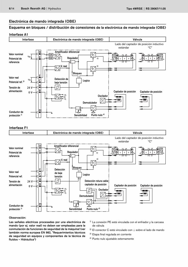
Electrónica de mando integrada (OBE)
Esquema en bloques / distribución de conexiones de la electrónica de mando integrada (OBE)
Interfase A1Interfase Electrónica de mando integrada (OBE) Válvula
Lado del captador de posición inductivo estándar “C”
Punto nulo 4)Sensibilidad
Valor nominal
Potencial de referencia
Valor real
Potencial ref. 2) Lo gica
Tensión de alimentación
Conductor de protección 1)
V. real
Detección de baja tensión
Bloqueo
Amplificador diferencial
Regulador
Demodulador
Oscil a dor
3)
3)
Captador de posición Captador de posición
Interfase F1Interfase Electrónica de mando integrada (OBE) Válvula
Punto nulo 4)Sensibilidad
Valor nominal
Potencial de referencia
Valor real
Potencial ref.
Tensión de alimentación
Conductor de protección 1)
V. real
Detección de baja tensión
Bloqueo
Amplificador diferencial
Regulador
Demodulador
Oscil a dorCaptador de posición Captador de posición
3)
3)
Detección rotura cablecaptador de posición
Observación:
Las señales eléctricas procesadas por una electrónica de mando (por ej. valor real) no deben ser empleadas para la conmutación de funciones de seguridad de la máquina! (ver también norma europea EN 982, "Requerimientos técnicos de seguridad en equipos y componentes de la técnica de fluidos – Hidráulica“)
1) La conexión PE está vinculada con el enfriador y la carcasa de válvula
2) El conector C está vinculado con ⊥ sobre el lado de mando3) Etapa final regulada en corriente4) Punto nulo ajustable externamente
Lo gica
Lado del captador de posición inductivo estándar “C”
20
40
60
80
100
+2
–100
–80
–60
–40
–20
–2 –1 +1 –3 +3
20
40
60
80
100
+1 +2
–100
–80
–60
–40
–20
–2 –1
0
5
0 50 100 150 200 250 300 315210
2
1
4
3
0
1
2
0 50 100 150 200 250 300 315210
Hydraulics Bosch Rexroth AGRS 29067/11.05 tipo 4WRSE 7/14
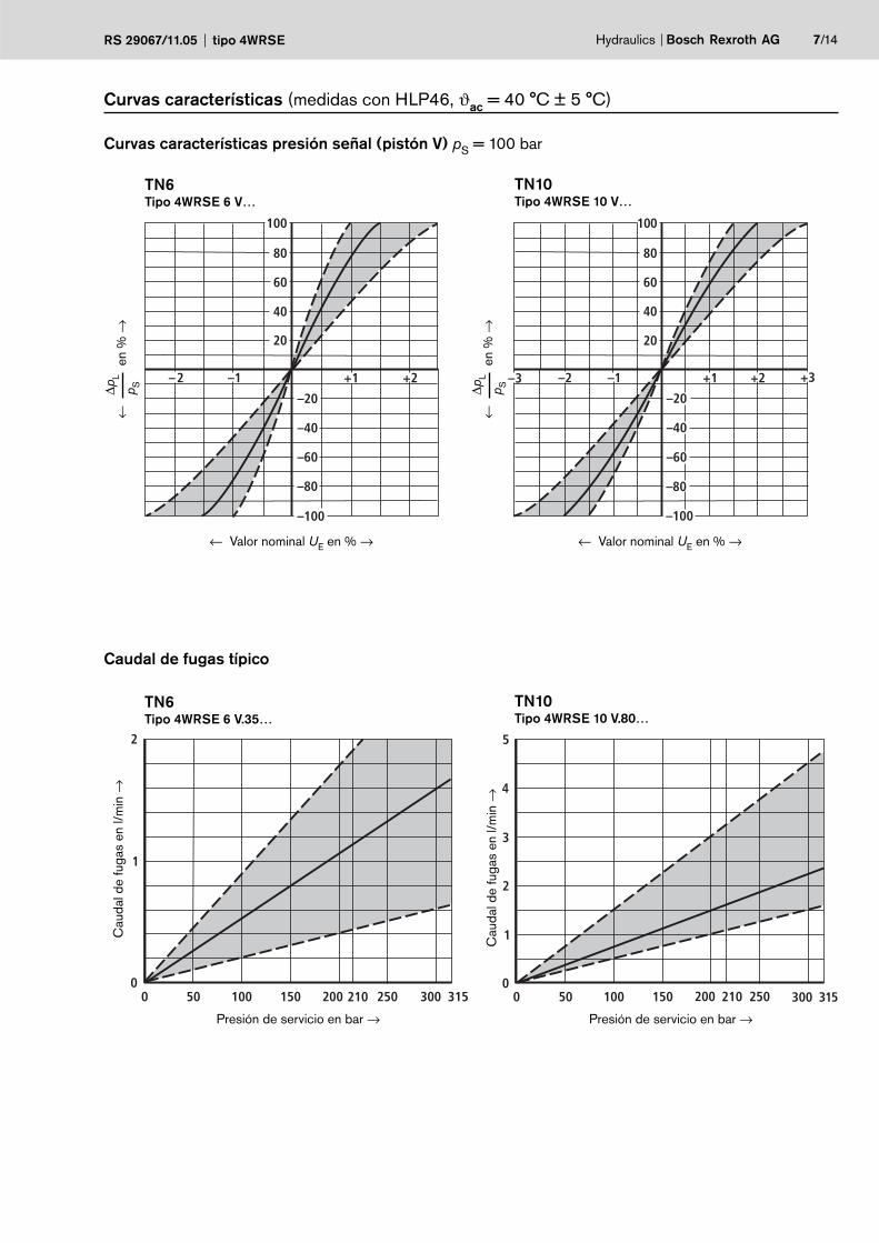
Curvas características (medidas con HLP46, ϑac = 40 °C ± 5 °C)
Curvas características presión señal (pistón V) pS = 100 bar
TN6 Tipo 4WRSE 6 V…
TN10 Tipo 4WRSE 10 V…
Cau
dal d
e fu
gas
en l/
min
→
Presión de servicio en bar → Presión de servicio en bar →
Cau
dal d
e fu
gas
en l/
min
→
Caudal de fugas típico
TN6 Tipo 4WRSE 6 V.35…
TN10 Tipo 4WRSE 10 V.80…
← Valor nominal UE en % →
∆pL
p S
←
en
% →
∆pL
p S
←
en
% →
← Valor nominal UE en % →
8/14 Bosch Rexroth AG Hydraulics Tipo 4WRSE RS 29067/11.05
0 25 50 75 100
100
80
60
40
20
10
1 2
P → B
B → T
P → A
A → T
100
60
40
– 100 – 80 0
20
020 100
80
– 60 – 20– 40 40 8060
– 15 7,5
Cau
dal e
n %
→
Valor nominal en % →
Cau
dal e
n %
→
Valor nominal en % →
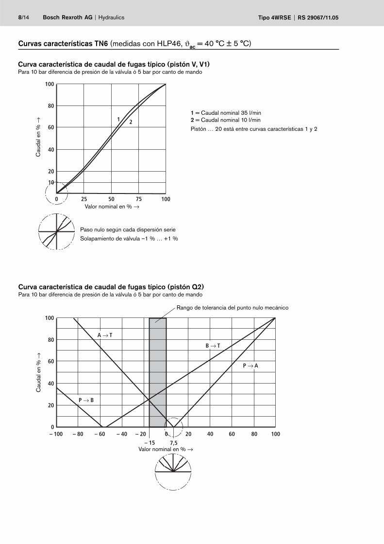
Paso nulo según cada dispersión serie
Solapamiento de válvula –1 % … +1 %
Curva característica de caudal de fugas típico (pistón V, V1) Para 10 bar diferencia de presión de la válvula ó 5 bar por canto de mando
Rango de tolerancia del punto nulo mecánico
1 = Caudal nominal 35 l/min2 = Caudal nominal 10 l/min
Pistón … 20 está entre curvas características 1 y 2
Curvas características TN6 (medidas con HLP46, ϑac = 40 °C ± 5 °C)
Curva característica de caudal de fugas típico (pistón Q2) Para 10 bar diferencia de presión de la válvula ó 5 bar por canto de mando
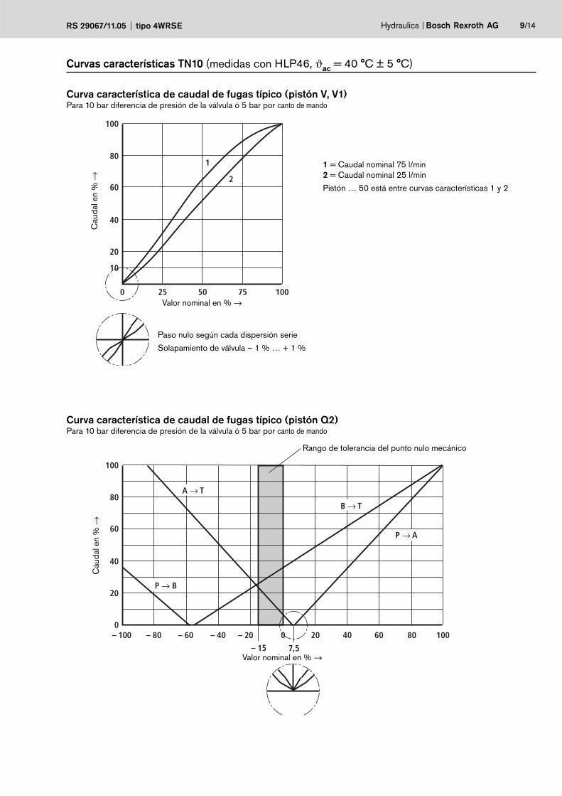
Hydraulics Bosch Rexroth AGRS 29067/11.05 tipo 4WRSE 9/14
P → B
B → T
P → A
A → T
100
60
40
– 100 – 80 0
20
020 100
80
– 60 – 20– 40 40 8060
– 15 7,5
0 25 50 75 100
100
80
60
40
20
10
1
2
Cau
dal e
n %
→
Valor nominal en % →
Cau
dal e
n %
→
Valor nominal en % →
Paso nulo según cada dispersión serie
Solapamiento de válvula – 1 % … + 1 %
Rango de tolerancia del punto nulo mecánico
1 = Caudal nominal 75 l/min2 = Caudal nominal 25 l/min
Pistón … 50 está entre curvas características 1 y 2
Curvas características TN10 (medidas con HLP46, ϑac = 40 °C ± 5 °C)
Curva característica de caudal de fugas típico (pistón V, V1) Para 10 bar diferencia de presión de la válvula ó 5 bar por canto de mando
Curva característica de caudal de fugas típico (pistón Q2) Para 10 bar diferencia de presión de la válvula ó 5 bar por canto de mando
10/14 Bosch Rexroth AG Hydraulics Tipo 4WRSE RS 29067/11.05
0
25
50
75
100
4020
0 – 25
0 10 20
0 – 50
0 – 75
0 –100
4030
Car
rera
en
% →
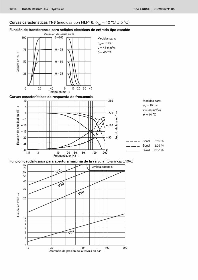
Variación de señal en %Función de transferencia para señales eléctricas de entrada tipo escalón
Tiempo en ms →
Medidas para:
pS = 10 bar
ν = 46 mm2/s
ϑ = 40 °C
10
0
– 5
– 10
– 15
– 20
– 25
– 301,5 10 20 30 100
– 270
– 180
– 90
0
5
– 360
3 20050
Curvas características de respuesta de frecuencia
Ang
ulo
de fa
se e
n °
→
Señal ±10 %
Señal ±25 %
Señal ±100 %
Rel
ació
n de
am
plitu
d en
dB
→
Frecuencia en Hz →
Función caudal-carga para apertura máxima de la válvula (tolerancia ±10%)
Medidas para:
pS = 10 bar
ν = 46 mm2/s
ϑ = 40 °C
V10
V35
V20
V04
20
50
80
10
30
40
6070
3
4
5
678
10 20 50 100 200
Cau
dal e
n l/m
in →
Diferencia de presión de la válvula en bar →
Curvas características TN6 (medidas con HLP46, ϑac = 40 °C ± 5 °C)
Límites potencia
V25
V50
20
50
100
10 20 50 10010
200
200
300
180
V80
0
25
50
75
100
4020
0 – 25
0 20
0 – 50
0 – 75
0 –100
40
10
0
– 5
– 10
– 15
– 20
– 25
– 301,5 10 20 30 100
– 270
– 180
– 90
0
5
– 360
3 20050
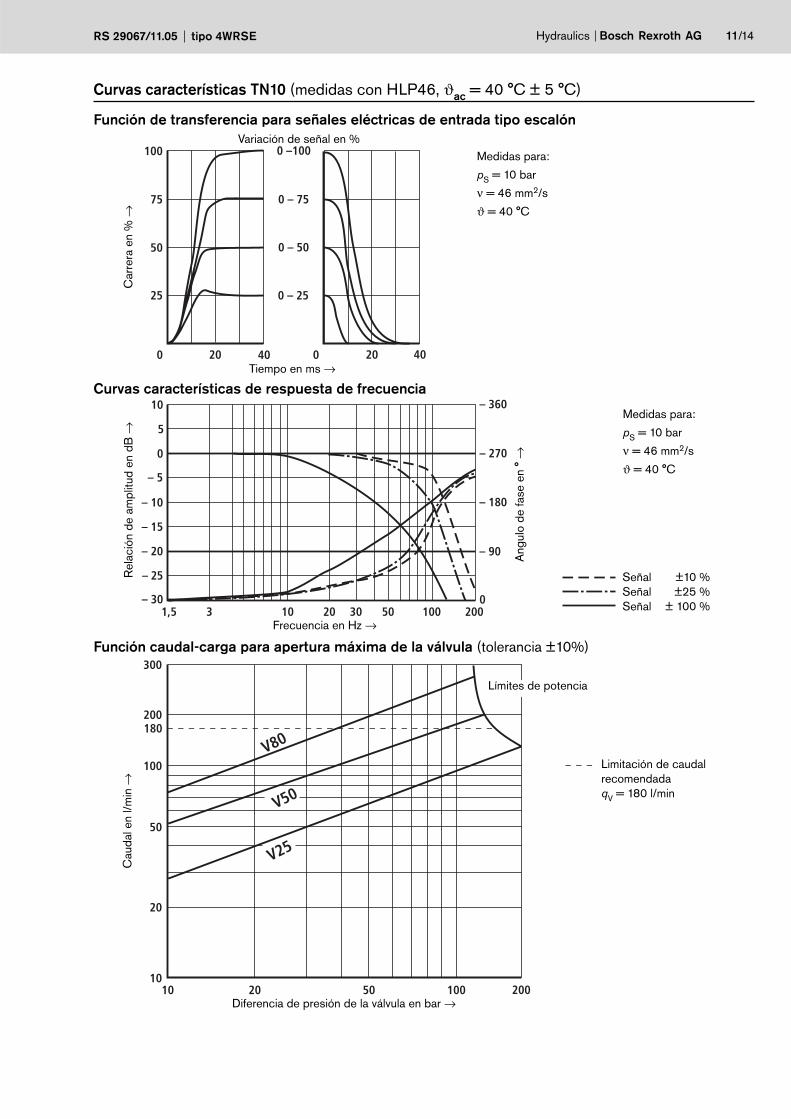
Hydraulics Bosch Rexroth AGRS 29067/11.05 tipo 4WRSE 11/14
Función de transferencia para señales eléctricas de entrada tipo escalónR
elac
ión
de a
mpl
itud
en d
B →
Frecuencia en Hz →
Curvas características de respuesta de frecuencia
Car
rera
en
% →
Variación de señal en %
Tiempo en ms →
Ang
ulo
de fa
se e
n °
→
Señal ±10 %Señal ±25 %Señal ± 100 %
Función caudal-carga para apertura máxima de la válvula (tolerancia ±10%)
Limitación de caudalrecomendadaqV = 180 l/min
Medidas para:
pS = 10 bar
ν = 46 mm2/s
ϑ = 40 °C
Medidas para:
pS = 10 bar
ν = 46 mm2/s
ϑ = 40 °C
Cau
dal e
n l/m
in →
Diferencia de presión de la válvula en bar →
Curvas características TN10 (medidas con HLP46, ϑac = 40 °C ± 5 °C)
Límites de potencia
91 15
129
13135,5 7640,5
252
BA
"a" "b"
40
6
5
471
2.282.1
22
45
9115
129
11,513476 40,5
252
BA
"a" "b"
40
3.2 3.1
22
9
47
67
8
13,5
T
PA
F4 F3
BF1 F2
12/14 Bosch Rexroth AG Hydraulics Tipo 4WRSE RS 29067/11.05
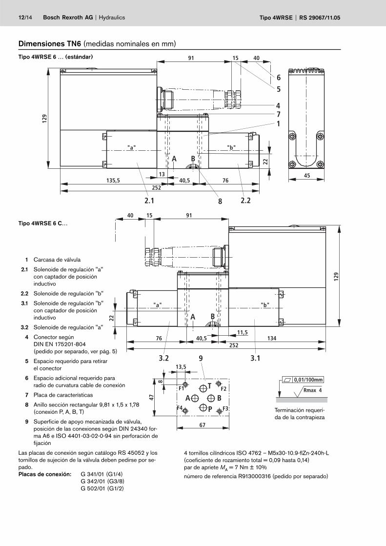
4 tornillos cilíndricos ISO 4762 – M5x30-10.9-flZn-240h-L (coeficiente de rozamiento total = 0,09 hasta 0,14)par de apriete MA = 7 Nm ± 10%
número de referencia R913000316 (pedido por separado)
Rmax 4
0,01/100mm
Dimensiones TN6 (medidas nominales en mm)
Tipo 4WRSE 6 C…
Tipo 4WRSE 6 … (estándar)
Terminación requeri-da de la contrapieza
1 Carcasa de válvula
2.1 Solenoide de regulación "a" con captador de posicióninductivo
2.2 Solenoide de regulación "b"
3.1 Solenoide de regulación "b" con captador de posicióninductivo
3.2 Solenoide de regulación "a"
4 Conector según DIN EN 175201-804(pedido por separado, ver pág. 5)
5 Espacio requerido para retirar el conector
6 Espacio adicional requerido para radio de curvatura cable de conexión
7 Placa de características
8 Anillo sección rectangular 9,81 x 1,5 x 1,78 (conexión P, A, B, T)
9 Superficie de apoyo mecanizada de válvula, posición de las conexiones según DIN 24340 for-ma A6 e ISO 4401-03-02-0-94 sin perforación de fijación
Las placas de conexión según catálogo RS 45052 y los tornillos de sujeción de la válvula deben pedirse por se-pado.Placas de conexión: G 341/01 (G1/4) G 342/01 (G3/8) G 502/01 (G1/2)
BA
"a" "b"
2416154102
317
911540
153
9 3.1
3.2
30
112
29
72
13
F1 F2
BA
T1TF3F4
P
32,5
±0,2
50,8±0,2
70
BA
"a" "b"
24161 54 102
317
91 15 4015
365
72.2
12.1 8
4
30
Hydraulics Bosch Rexroth AGRS 29067/11.05 tipo 4WRSE 13/14
Rmax 4
0,01/100mm
Terminación requeri-da de la contrapieza
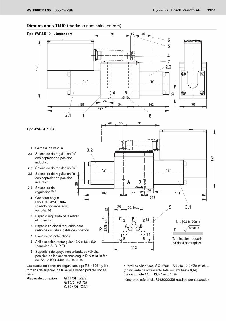
Dimensiones TN10 (medidas nominales en mm)
Tipo 4WRSE 10 … (estándar)
Tipo 4WRSE 10 C…
1 Carcasa de válvula
2.1 Solenoide de regulación "a" con captador de posicióninductivo
2.2 Solenoide de regulación "b"
3.1 Solenoide de regulación "b" con captador de posicióninductivo
3.2 Solenoide de regulación "a"
4 Conector según DIN EN 175201-804(pedido por separado, ver pág. 5)
5 Espacio requerido para retirar el conector
6 Espacio adicional requerido para radio de curvatura cable de conexión
7 Placa de características
8 Anillo sección rectangular 13,0 x 1,6 x 2,0 (conexión A, B, P, T)
9 Superficie de apoyo mecanizada de válvula, posición de las conexiones según DIN 24340 for-ma A10 e ISO 4401-05-04-0-94
Las placas de conexión según catálogo RS 45054 y los tornillos de sujeción de la válvula deben pedirse por se-pado.Placas de conexión: G 66/01 (G3/8) G 67/01 (G1/2) G 534/01 (G3/4)
4 tornillos cilíndricos ISO 4762 – M6x40-10.9-flZn-240h-L(coeficiente de rozamiento total = 0,09 hasta 0,14)par de apriete MA = 12,5 Nm ± 10%
número de referencia R913000058 (pedido por separado)

Bosch Rexroth AGHydraulicsZum Eisengießer 197816 Lohr am Main, GermanyTelefon +49 (0) 93 52 / 18-0Telefax +49 (0) 93 52 / 18-23 [email protected]
© Todos los derechos de Bosch Rexroth AG, también para el caso de so-licitudes de derechos protegidos. Nos reservamos todas las capacidades dispositivas tales como derechos de copia y de tramitación.Los datos indicados sirven sólo para describir el producto. De nuestras especificaciones no puede derivarse ninguna declaración sobre una cierta composición o idoneidad para un cierto fin de empleo. Las especificaciones no liberan al usuario de las propias evaluaciones y verificaciones. Hay que tener en cuenta que nuestros productos están sometidos a un proceso na-tural de desgaste y envejecimiento.
14/14 Bosch Rexroth AG Hydraulics Tipo 4WRSE RS 29067/11.05
Notas
4WRSEH 1/18 RE 29 069/02.03
© 2003by Bosch Rexroth AG, Industrial Hydraulics, D-97813 Lohr am Main
All rights reserved. No part of this document may be reproduced or stored, processed, duplicated or circulated usingelectronic systems, in any form or by means, without the prior written authorisation of Bosch Rexroth AG. In the eventof contravention of the above provisions, the contravening party is obliged to pay compensation.
RE 29 069/02.03Replaces: 12.99
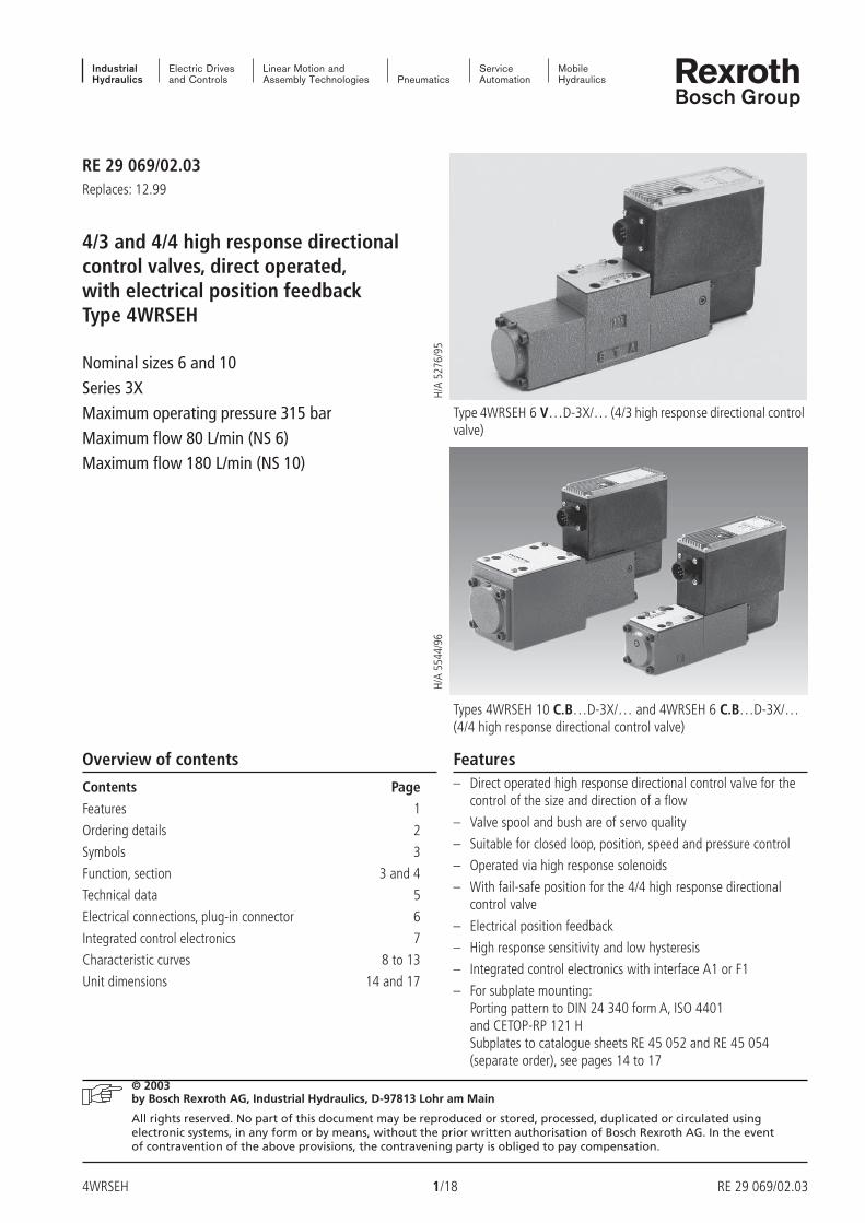
4/3 and 4/4 high response directionalcontrol valves, direct operated,with electrical position feedbackType 4WRSEH
Nominal sizes 6 and 10Series 3XMaximum operating pressure 315 barMaximum flow 80 L/min (NS 6)Maximum flow 180 L/min (NS 10)
H/A
5276
/95
H/A
5544
/96
Overview of contents Features
Contents Page
Features 1
Ordering details 2
Symbols 3
Function, section 3 and 4
Technical data 5
Electrical connections, plug-in connector 6
Integrated control electronics 7
Characteristic curves 8 to 13
Unit dimensions 14 and 17
Type 4WRSEH 6 V…D-3X/… (4/3 high response directional controlvalve)
Types 4WRSEH 10 C.B…D-3X/… and 4WRSEH 6 C.B…D-3X/…(4/4 high response directional control valve)
– Direct operated high response directional control valve for thecontrol of the size and direction of a flow
– Valve spool and bush are of servo quality
– Suitable for closed loop, position, speed and pressure control
– Operated via high response solenoids
– With fail-safe position for the 4/4 high response directionalcontrol valve
– Electrical position feedback
– High response sensitivity and low hysteresis
– Integrated control electronics with interface A1 or F1
– For subplate mounting:Porting pattern to DIN 24 340 form A, ISO 4401and CETOP-RP 121 HSubplates to catalogue sheets RE 45 052 and RE 45 054(separate order), see pages 14 to 17

RE 29 069/02.03 2/18 4WRSEH
P T
A B
a 0 b
a 0
P T
A B
b
P T
A B
a 0 b ba G
G
P T
A B
a 0 b ba
A B
P T
a 0 b ba G
G
A B
P T
a 0 b ba
Ordering details
Further detailsin clear text
V = FKM seals,suitable for mineral oils
(HL, HLP) to DIN 51 524and phosphate ester
(HFD-R)
Control electronicsinterface
A1 = Command value input ± 10 V
F1 = Command value input 4 to 20 mA
Electrical connections
K0 = With component plug toE DIN 43 563-AM6
Without plug-in connector,Plug-in connector – separate order,
see page 6
Control electronics power supply
G24 = + 24 V DC
3X = Series 30 to 39(30 to 39: unchanged installation and connection dimensions)
Spool overlap 4)
E = 0...0.5% negativeD = 0...0.5% positive
Flow characteristics
L = LinearP = Inflected characteristic curve 40 %
Nominal flow at a 70 bar pressure differential
Nominal size 6 04 = 3) 4 L/min 12 = 12 L/min 24 = 24 L/min 40 = 2) 40 L/min 50 = 1) 50 L/min
Nominal size 10 50 = 50 L/min100 = 100 L/min
4WRS E H –3X /G24 K0 / V *
With integratedcontrol electronics = EControl spool/bush = H
Nominal size 6 = 6Nominal size 10 = 10
(Standard) = No code
= C
Symbols
Inductive position transducer locationwith spool symbol „V“
= V
1) Only with „V“ in conjunction with flow characteristic „L“2) Only with „C“ and „V“ in conjunction with flow characteristic „P“3) Only in conjunction with flow characteristic „L“4) The spool overlap in % relates to the nominal stroke of the control spool.
We recommend, for closed loop applications, the D overlap.Further spool overlaps on request!
= C3
= C4
Inductive position transducer locationwith spool symbols „C3“ and „C4“
(Standard) = B
4/3-way version
4/4-way version
= No code
4WRSEH 3/18 RE 29 069/02.03
P T
A B
a 0 b ba G
A B
P T
a 0 b ba G G
A B
P T
a 0 b ba
G
P T
A B
a 0 b ba
"a" "b"
PA BTA TB
10
468 23 5 7
9
1
Function, section
Symbols
Type 4WRSEH.V…-3X… Type 4WRSEH.VC…-3X/…
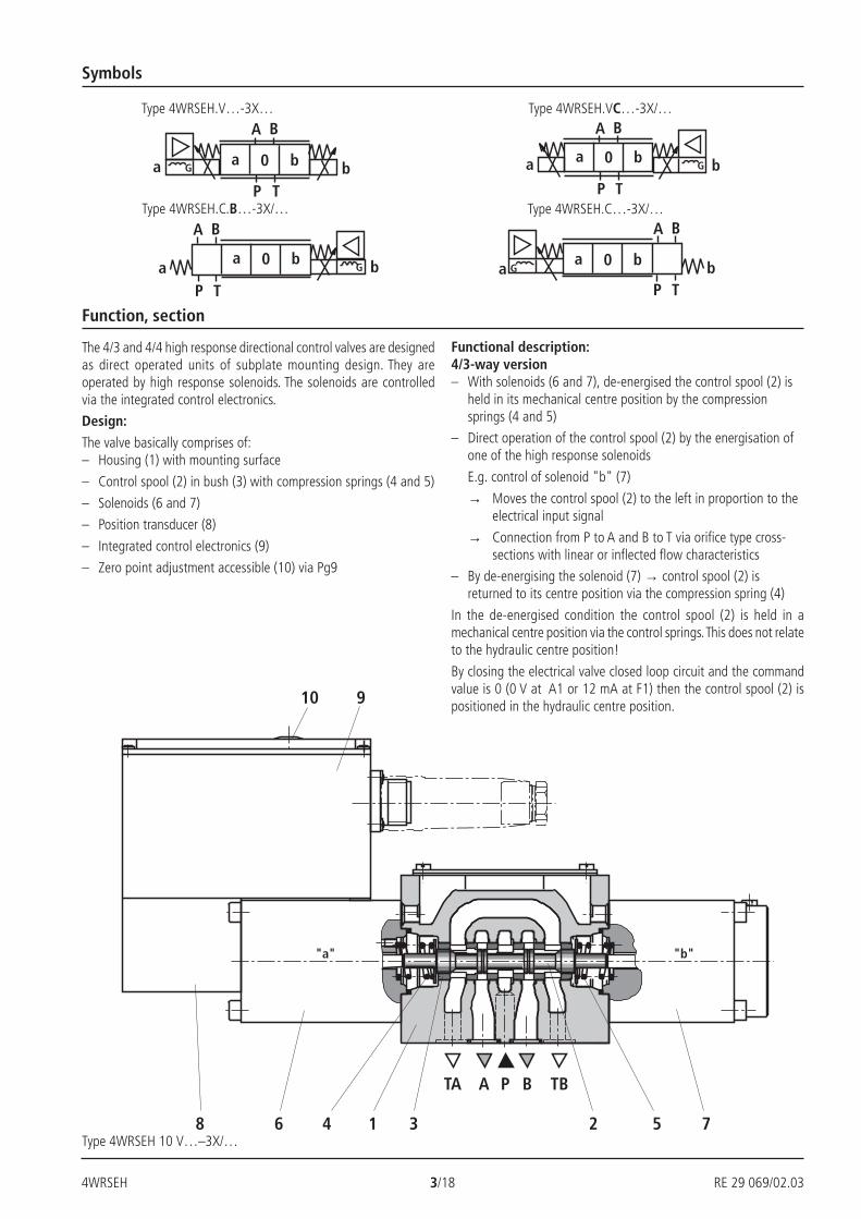
The 4/3 and 4/4 high response directional control valves are designedas direct operated units of subplate mounting design. They areoperated by high response solenoids. The solenoids are controlledvia the integrated control electronics.
Design:
The valve basically comprises of:– Housing (1) with mounting surface
– Control spool (2) in bush (3) with compression springs (4 and 5)
– Solenoids (6 and 7)
– Position transducer (8)
– Integrated control electronics (9)
– Zero point adjustment accessible (10) via Pg9
Type 4WRSEH 10 V…–3X/…
Type 4WRSEH.C.B…-3X/… Type 4WRSEH.C…-3X/…
Functional description:4/3-way version– With solenoids (6 and 7), de-energised the control spool (2) is
held in its mechanical centre position by the compressionsprings (4 and 5)
– Direct operation of the control spool (2) by the energisation ofone of the high response solenoids
E.g. control of solenoid "b" (7)
→ Moves the control spool (2) to the left in proportion to theelectrical input signal
→ Connection from P to A and B to T via orifice type cross-sections with linear or inflected flow characteristics
– By de-energising the solenoid (7) → control spool (2) isreturned to its centre position via the compression spring (4)
In the de-energised condition the control spool (2) is held in amechanical centre position via the control springs. This does not relateto the hydraulic centre position!
By closing the electrical valve closed loop circuit and the commandvalue is 0 (0 V at A1 or 12 mA at F1) then the control spool (2) ispositioned in the hydraulic centre position.
RE 29 069/02.03 4/18 4WRSEH
P BA TBTA
8
2 5 71 36
9
4
Function, section
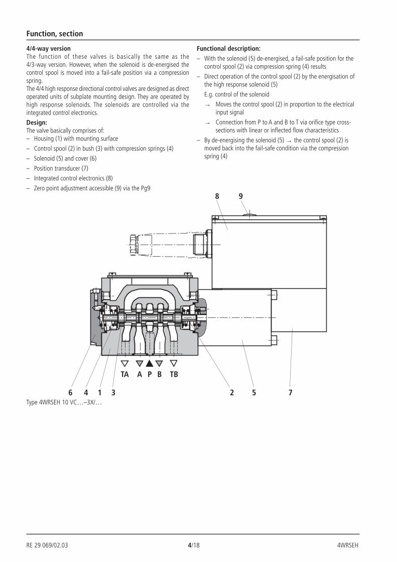
4/4-way versionThe function of these valves is basically the same as the4/3-way version. However, when the solenoid is de-energised thecontrol spool is moved into a fail-safe position via a compressionspring.The 4/4 high response directional control valves are designed as directoperated units of subplate mounting design. They are operated byhigh response solenoids. The solenoids are controlled via theintegrated control electronics.
Design:The valve basically comprises of:– Housing (1) with mounting surface
– Control spool (2) in bush (3) with compression springs (4)
– Solenoid (5) and cover (6)
– Position transducer (7)
– Integrated control electronics (8)
– Zero point adjustment accessible (9) via the Pg9
Type 4WRSEH 10 VC…–3X/…
Functional description:
– With the solenoid (5) de-energised, a fail-safe position for thecontrol spool (2) via compression spring (4) results
– Direct operation of the control spool (2) by the energisation ofthe high response solenoid (5)
E.g. control of the solenoid
→ Moves the control spool (2) in proportion to the electricalinput signal
→ Connection from P to A and B to T via orifice type cross-sections with linear or inflected flow characteristics
– By de-energising the solenoid (5) → the control spool (2) ismoved back into the fail-safe condition via the compressionspring (4)
4WRSEH 5/18 RE 29 069/02.03
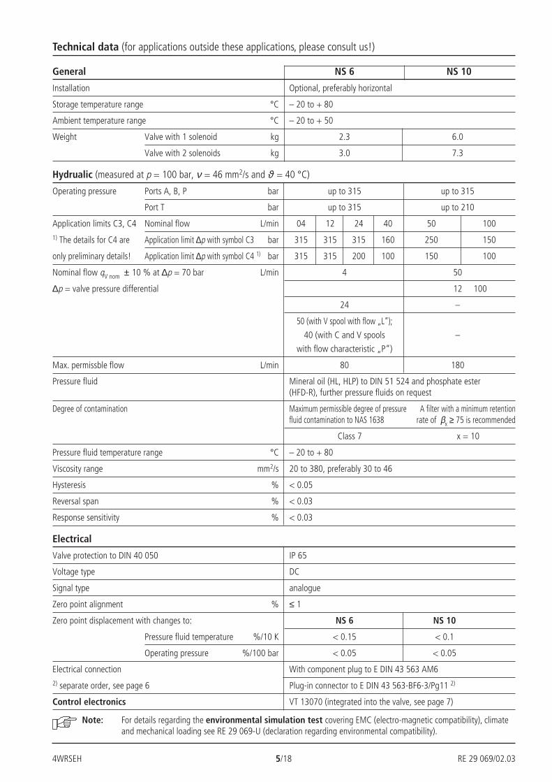
General NS 6 NS 10
Installation Optional, preferably horizontal
Storage temperature range °C – 20 to + 80
Ambient temperature range °C – 20 to + 50
Weight Valve with 1 solenoid kg 2.3 6.0
Valve with 2 solenoids kg 3.0 7.3
Hydrualic (measured at p = 100 bar, ν = 46 mm2/s and ϑ = 40 °C)
Operating pressure Ports A, B, P bar up to 315 up to 315
Port T bar up to 315 up to 210
Application limits C3, C4 Nominal flow L/min 04 12 24 40 50 1001) The details for C4 are Application limit ∆p with symbol C3 bar 315 315 315 160 250 150
only preliminary details! Application limit ∆p with symbol C4 1) bar 315 315 200 100 150 100
Nominal flow qV nom ± 10 % at ∆p = 70 bar L/min 4 50
∆p = valve pressure differential 12 100
24 –
50 (with V spool with flow „L“);
40 (with C and V spools –
with flow characteristic „P“)
Max. permissble flow L/min 80 180
Pressure fluid Mineral oil (HL, HLP) to DIN 51 524 and phosphate ester(HFD-R), further pressure fluids on request
Degree of contamination Maximum permissible degree of pressure A filter with a minimum retentionfluid contamination to NAS 1638 rate of βx ≥ 75 is recommended
Class 7 x = 10
Pressure fluid temperature range °C – 20 to + 80
Viscosity range mm2/s 20 to 380, preferably 30 to 46
Hysteresis % < 0.05
Reversal span % < 0.03
Response sensitivity % < 0.03
Electrical
Valve protection to DIN 40 050 IP 65
Voltage type DC
Signal type analogue
Zero point alignment % ≤ 1
Zero point displacement with changes to: NS 6 NS 10
Pressure fluid temperature %/10 K < 0.15 < 0.1
Operating pressure %/100 bar < 0.05 < 0.05
Electrical connection With component plug to E DIN 43 563 AM62) separate order, see page 6 Plug-in connector to E DIN 43 563-BF6-3/Pg11 2)
Control electronics VT 13070 (integrated into the valve, see page 7)
Note: For details regarding the environmental simulation test covering EMC (electro-magnetic compatibility), climateand mechanical loading see RE 29 069-U (declaration regarding environmental compatibility).
Technical data (for applications outside these applications, please consult us!)
RE 29 069/02.03 6/18 4WRSEH
Ø6,
5…Ø
11
A F
ED
C
BØ27
91
AB
CD
E
F
Ø8…
Ø13
,5
85
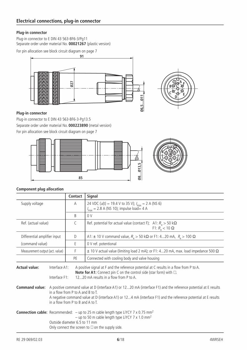
Component plug allocation
Plug-in connector
Plug-in connector to E DIN 43 563-BF6-3/Pg11Separate order under material No. 00021267 (plastic version)
For pin allocation see block circuit diagram on page 7
Electrical connections, plug-in connector
Actual value: Interface A1: A positive signal at F and the reference potential at C results in a flow from P to A.Note for A1: Connect pin C on the control side (star form) with ⊥ .
Interface F1: 12...20 mA results in a flow from P to A.
Command value: A positive command value at D (interface A1) or 12...20 mA (interface F1) and the reference potential at E resultsin a flow from P to A and B to T.A negative command value at D (interface A1) or 12...4 mA (interface F1) and the reference potential at E resultsin a flow from P to B and A to T.
Connection cable: Recommended: – up to 25 m cable length type LiYCY 7 x 0.75 mm2
– up to 50 m cable length type LiYCY 7 x 1.0 mm2
Outside diameter 6.5 to 11 mmOnly connect the screen to ⊥ on the supply side.
Contact Signal
Supply voltage A 24 VDC (u(t) = 19.4 V to 35 V); Imax = 2 A (NS 6)Imax = 2.8 A (NS 10); impulse load= 4 A
B 0 V
Ref. (actual value) C Ref. potential for actual value (contact F); A1: Re > 50 kΩ F1: Re < 10 Ω
Differential amplifier input D A1: ± 10 V command value, Re > 50 kΩ or F1: 4...20 mA, Re > 100 Ω
(command value) E 0 V ref. potentional
Measurement output (act. value) F ± 10 V actual value (limiting load 2 mA); or F1: 4...20 mA, max. load impedance 500 Ω
PE Connected with cooling body and valve housing
Plug-in connectorPlug-in connector to E DIN 43 563-BF6-3-Pg13.5
Separate order under material No. 000223890 (metal version)
For pin allocation see block circuit diagram on page 7
4WRSEH 7/18 RE 29 069/02.03
≈=
+Ui
–Ui0VU
U
B
A
C
F
E
D
UI
UI
0V
24V
=≈PE
P T
A B
a 0 b ba G G
P T
A B
a 0 b ba
+Ui
–Ui0VU
U
B
A
C
F
E
D
UI
0V
24V
= ≈PE
≈=
P T
A B
a 0 ba
G b a 0 ba G b
P T
A B
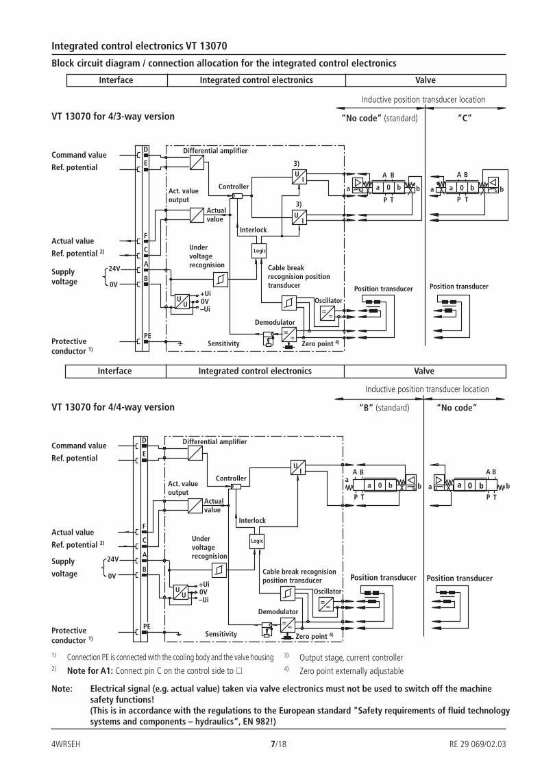
Interface
Block circuit diagram / connection allocation for the integrated control electronics
Integrated control electronics VT 13070
Note: Electrical signal (e.g. actual value) taken via valve electronics must not be used to switch off the machinesafety functions!(This is in accordance with the regulations to the European standard "Safety requirements of fluid technologysystems and components – hydraulics“, EN 982!)
Integrated control electronics Valve
Inductive position transducer location
“No code” (standard) “C”
Zero point 4)Sensitivity
Command value
Ref. potential
Actual value
Ref. potential 2) Logic
Supplyvoltage
Protectiveconductor 1)
Actualvalue
Undervoltagerecognision
Interlock
Differential amplifier
Controller
Demodulator
Oscillator
3)
3)
Cable breakrecognision positiontransducer
Act. valueoutput
Position transducer Position transducer
1) Connection PE is connected with the cooling body and the valve housing2) Note for A1: Connect pin C on the control side to ⊥
Interface Integrated control electronics Valve
VT 13070 for 4/3-way version
VT 13070 for 4/4-way version
Zero point 4)
3) Output stage, current controller4) Zero point externally adjustable
Inductive position transducer location
“B“ (standard) “No code”
Command value
Ref. potential
Actual value
Ref. potential 2)
Supply
voltage
Protectiveconductor 1)
Actualvalue
Differential amplifier
Controller
Undervoltagerecognision
Sensitivity
Logic
Interlock
Demodulator
Oscillator
Position transducer Position transducer
Act. valueoutput
Cable break recognisionposition transducer
RE 29 069/02.03 8/18 4WRSEH
– 100
– 80
– 60
– 40
– 20
20
40
60
80
100
+ 1 + 2 – 2 – 1
20
40
60
80
100
– 100
– 80
– 60
– 40
– 20
+ 1 + 2 – 2 – 1
0,5
1
0 50 100 150 200 250 300 315210
1
2
0 50 100 150 200 250 300 315210
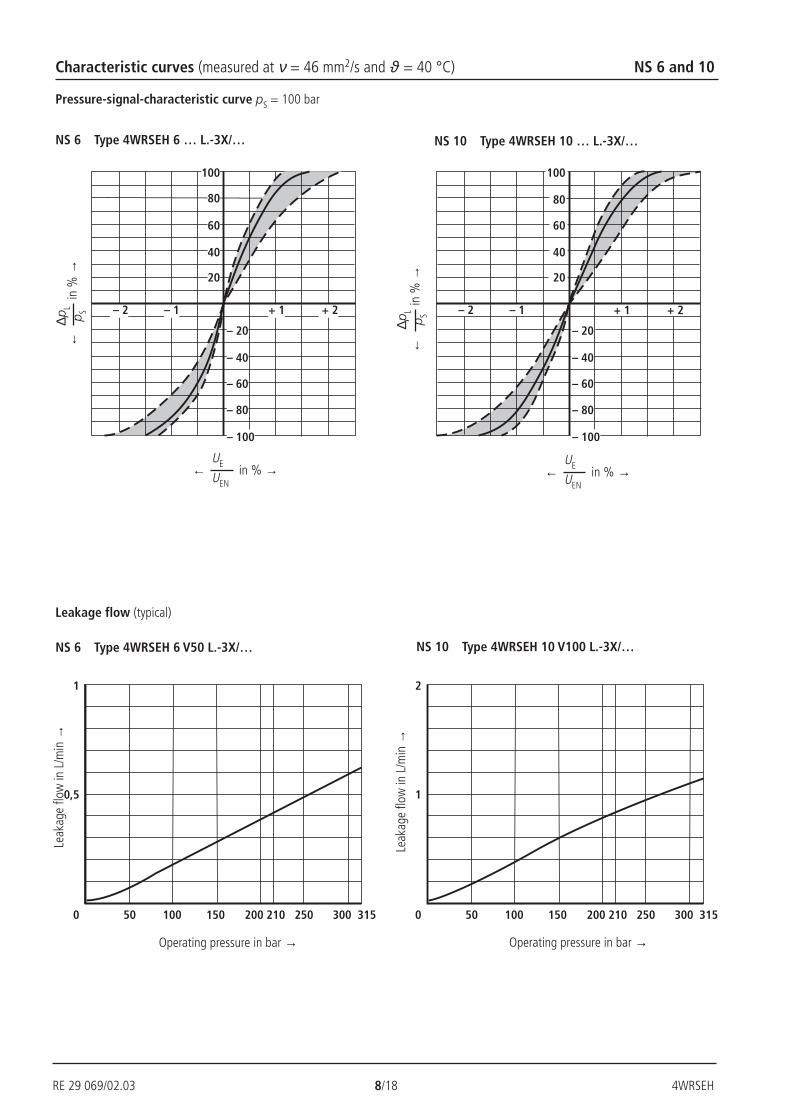
Characteristic curves (measured at ν = 46 mm2/s and ϑ = 40 °C) NS 6 and 10
Pressure-signal-characteristic curve pS = 100 bar
NS 6 Type 4WRSEH 6 … L.-3X/…
∆pL
p S←
in %
→
← in % →UE
UEN
Leak
age
flow
in L
/min
→
Operating pressure in bar → Operating pressure in bar →
Leak
age
flow
in L
/min
→
Leakage flow (typical)
NS 10 Type 4WRSEH 10 … L.-3X/…
NS 6 Type 4WRSEH 6 V50 L.-3X/… NS 10 Type 4WRSEH 10 V100 L.-3X/…
∆pL
p S←
in %
→
← in % →UE
UEN
4WRSEH 9/18 RE 29 069/02.03
– 0,5% 0,5%
0 25 50 75 10040
100
80
60
40
20
10
0 25 50 75 10040
0,5%–0,5%
100
80
60
40
20
10
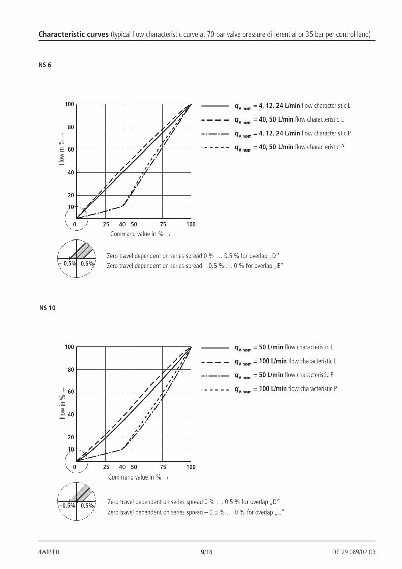
Characteristic curves (typical flow characteristic curve at 70 bar valve pressure differential or 35 bar per control land)
Flow
in %
→
Command value in % →
Flow
in %
→
Command value in % →
Zero travel dependent on series spread 0 % … 0.5 % for overlap „D“
Zero travel dependent on series spread – 0.5 % … 0 % for overlap „E“
NS 6
NS 10
Zero travel dependent on series spread 0 % … 0.5 % for overlap „D“
Zero travel dependent on series spread – 0.5 % … 0 % for overlap „E“
qV nom = 4, 12, 24 L/min flow characteristic L
qV nom = 40, 50 L/min flow characteristic L
qV nom = 4, 12, 24 L/min flow characteristic P
qV nom = 40, 50 L/min flow characteristic P
qV nom = 50 L/min flow characteristic L
qV nom = 100 L/min flow characteristic L
qV nom = 50 L/min flow characteristic P
qV nom = 100 L/min flow characteristic P
RE 29 069/02.03 10/18 4WRSEH
0 – 25
0 – 50
0 – 75
0 –100
0
25
50
75
100
2010 0 10 20 5 15 5 152010 0 10 200
25
50
75
100
0 – 25
0 – 50
0 – 75
0 –100
–270
–180
–90
0
–360
1,5 10 20 30 1003 20050
10
0
– 5
– 10
– 15
– 20
– 25
– 30
5
10
0
– 5
– 10
– 15
– 20
– 25
– 30
5
1,5 10 20 30 1003 20050
–270
–180
–90
0
–360
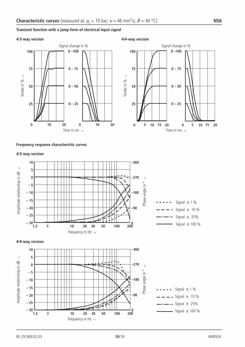
Frequency response characteristic curvesPh
ase
angl
e in
° →
Signal ± 1 %
Signal ± 10 %
Signal ± 25%
Signal ± 100 %
Ampl
itude
rela
tions
hip
in d
B →
Frequency in Hz →
Stro
ke in
% →
Signal change in %
Characteristic curves (measured at: pS = 10 bar; ν = 46 mm2/s; ϑ = 40 °C) NS6
Time in ms →
4/3-way version 4/4-way version
4/3-way version
4/4-way version
Signal ± 1 %
Signal ± 10 %
Signal ± 25%
Signal ± 100 %
Phas
e an
gle
in °
→
Ampl
itude
rela
tions
hip
in d
B →
Frequency in Hz →
Stro
ke in
% →
Signal change in %
Time in ms →
Transient function with a jump form of electrical input signal
4WRSEH 11/18 RE 29 069/02.03
20
50
80
10
30
40
60
1
2
3
45
70
10 20 50 100 20016030 40 70
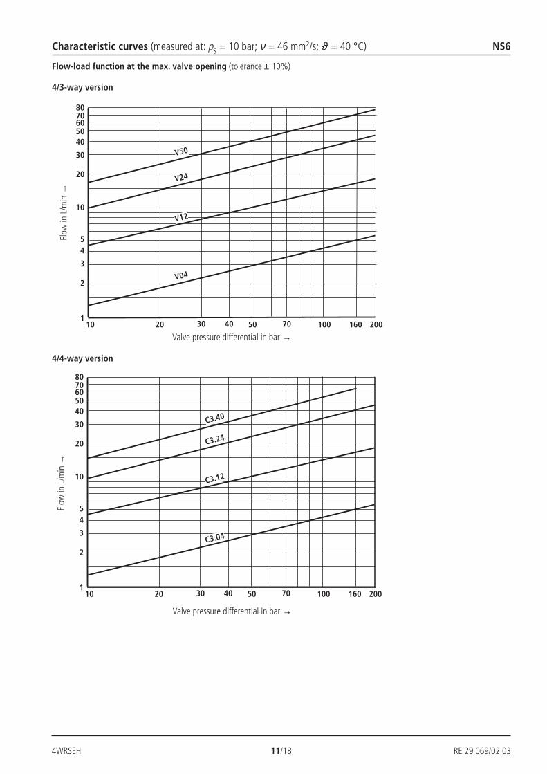
V50
V24
V12
V04
20
50
80
10
30
40
60
1
2
3
45
70
10 20 50 100 20016030 40 70
C3.40
C3.24
C3.12
C3.04
Flow-load function at the max. valve opening (tolerance ± 10%)Fl
ow in
L/m
in →
Valve pressure differential in bar →
4/3-way version
4/4-way version
Flow
in L
/min
→
Valve pressure differential in bar →
Characteristic curves (measured at: pS = 10 bar; ν = 46 mm2/s; ϑ = 40 °C) NS6
RE 29 069/02.03 12/18 4WRSEH
25
50
75
100
0 2010 0 10 2025
0 – 25
0 – 50
0 – 75
0 –100
25
50
75
100
0 10 200 2010 15 15 2525 55
0 – 25
0 – 50
0 – 75
0 –100
10
0
– 5
– 10
– 15
– 20
– 25
– 30
5
1,5 10 20 30 1003 200500
–270
–180
–90
–360
1,5 10 20 30 1003 20050
–270
–180
–90
0
–36010
0
– 5
– 10
– 15
– 20
– 25
– 30
5
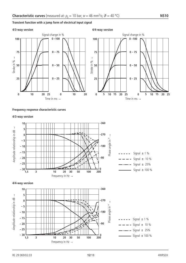
Frequency response characteristic curvesPh
ase
angl
e in
° →
Signal ± 1 %
Signal ± 10 %
Signal ± 25%
Signal ± 100 %
Ampl
itude
rela
tions
hip
in d
B →
Frequency in Hz →
Stro
ke in
% →
Signal change in %
Characteristic curves (measured at: pS = 10 bar; ν = 46 mm2/s; ϑ = 40 °C) NS10
Time in ms →
4/3-way version 4/4-way version
4/3-way version
4/4-way version
Signal ± 1 %
Signal ± 10 %
Signal ± 25%
Signal ± 100 %
Phas
e an
gle
in °
→
Ampl
itude
rela
tions
hip
in d
B →
Frequency in Hz →
Stro
ke in
% →
Signal change in %
Time in ms →
Transient function with a jump form of electrical input signal
4WRSEH 13/18 RE 29 069/02.03
20
50
100
10
200
300
180
10 20 50 100 20070
V50
V100
20
50
100
10
200
300
10 20 50 100 20070 150
C3.50
C3.100
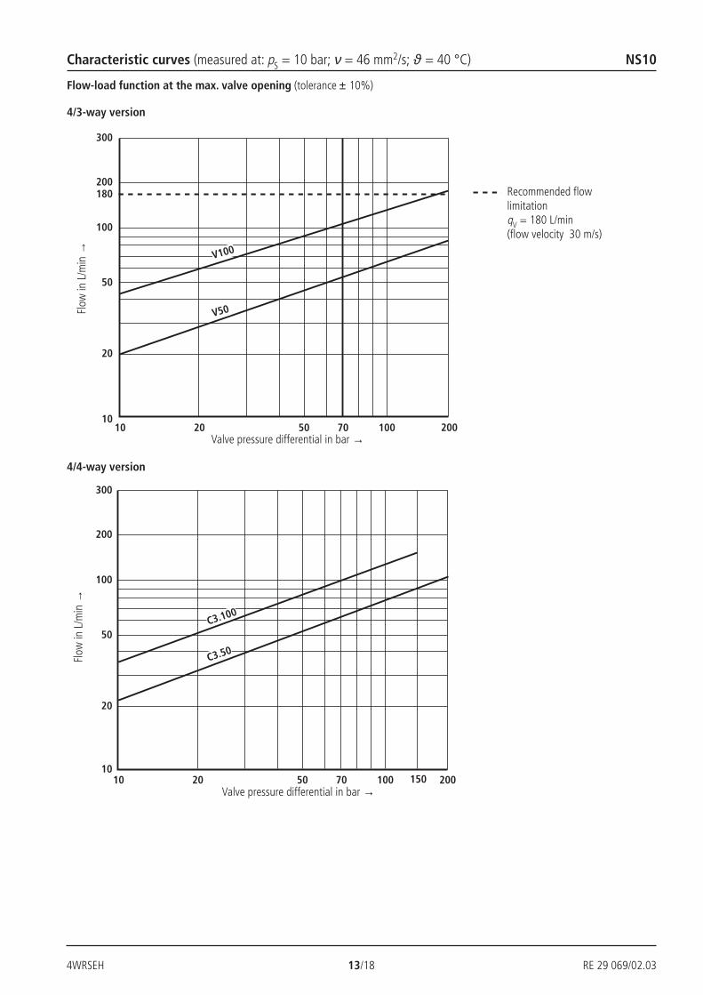
Recommended flowlimitationqV = 180 L/min(flow velocity 30 m/s)
Flow-load function at the max. valve opening (tolerance ± 10%)Fl
ow in
L/m
in →
Valve pressure differential in bar →
4/3-way version
4/4-way version
Flow
in L
/min
→
Valve pressure differential in bar →
Characteristic curves (measured at: pS = 10 bar; ν = 46 mm2/s; ϑ = 40 °C) NS10
RE 29 069/02.03 14/18 4WRSEH
0,01/100mm
R 4max
A B"b""a"
91 15 40
R40 6
574
1
11,5134 40,5 77
45
251,5
2.1 9 2.2
129
22
10
TA B
P
12,5 40,5
67
318
0,75
31,7
5
47
A B"b""a"
911540
R40
11,540,5
251,5
129
22
75,5 135,5
3.2 3.1
5 8
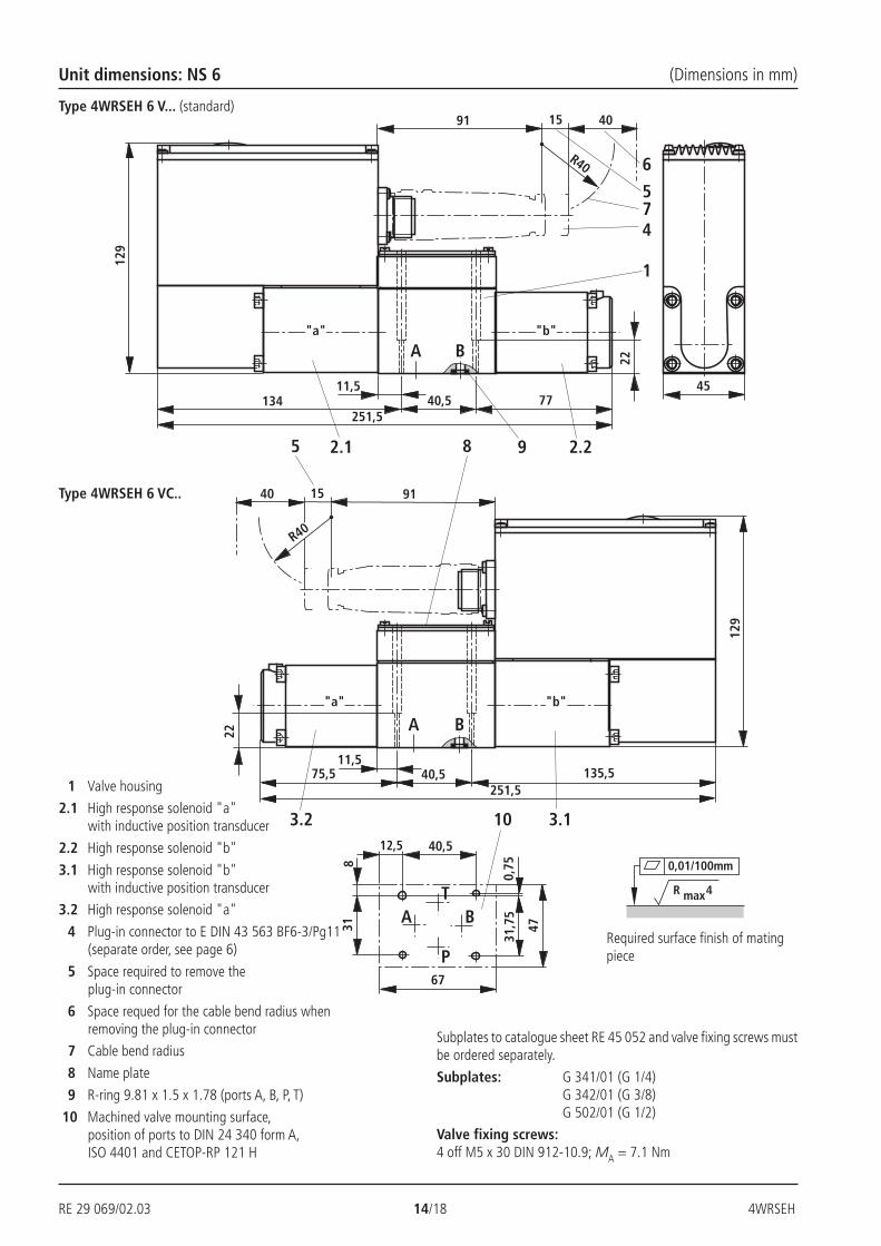
Unit dimensions: NS 6 (Dimensions in mm)
Type 4WRSEH 6 VC..
Type 4WRSEH 6 V... (standard)
Required surface finish of matingpiece
1 Valve housing
2.1 High response solenoid "a"with inductive position transducer
2.2 High response solenoid "b"
3.1 High response solenoid "b"with inductive position transducer
3.2 High response solenoid "a"
4 Plug-in connector to E DIN 43 563 BF6-3/Pg11(separate order, see page 6)
5 Space required to remove theplug-in connector
6 Space requed for the cable bend radius whenremoving the plug-in connector
7 Cable bend radius
8 Name plate
9 R-ring 9.81 x 1.5 x 1.78 (ports A, B, P, T)
10 Machined valve mounting surface,position of ports to DIN 24 340 form A,ISO 4401 and CETOP-RP 121 H
Subplates to catalogue sheet RE 45 052 and valve fixing screws mustbe ordered separately.
Subplates: G 341/01 (G 1/4)G 342/01 (G 3/8)G 502/01 (G 1/2)
Valve fixing screws:4 off M5 x 30 DIN 912-10.9; MA = 7.1 Nm
4WRSEH 15/18 RE 29 069/02.03
0,01/100mm
R 4max
A B
"b""a"
911540
R40
11,5 40,5
129
22
135,5202
65
7
4
8
2
3.2
9
1 3.1
45
10
TA B
P
12,5 40,5
67
831
0,75
31,7
5
47
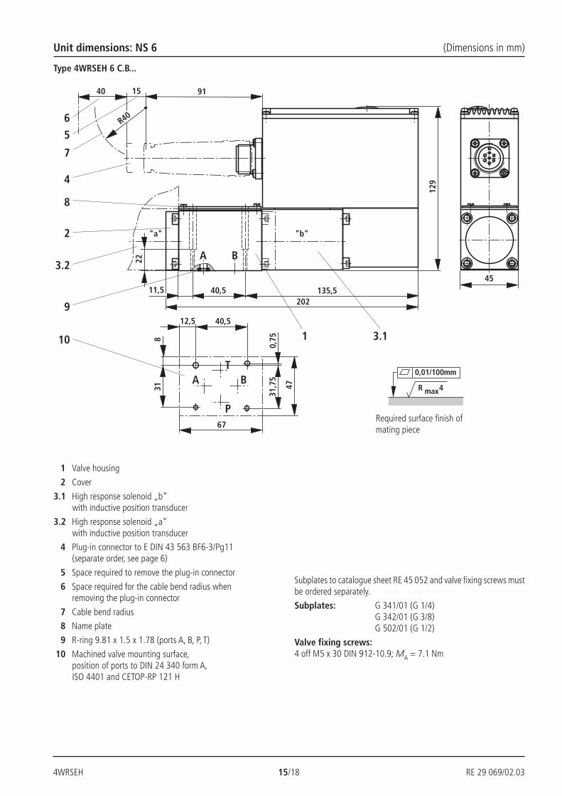
Unit dimensions: NS 6 (Dimensions in mm)
Type 4WRSEH 6 C.B...
Required surface finish ofmating piece
1 Valve housing
2 Cover
3.1 High response solenoid „b“with inductive position transducer
3.2 High response solenoid „a“with inductive position transducer
4 Plug-in connector to E DIN 43 563 BF6-3/Pg11(separate order, see page 6)
5 Space required to remove the plug-in connector
6 Space required for the cable bend radius whenremoving the plug-in connector
7 Cable bend radius
8 Name plate
9 R-ring 9.81 x 1.5 x 1.78 (ports A, B, P, T)
10 Machined valve mounting surface,position of ports to DIN 24 340 form A,ISO 4401 and CETOP-RP 121 H
Subplates to catalogue sheet RE 45 052 and valve fixing screws mustbe ordered separately.
Subplates: G 341/01 (G 1/4)G 342/01 (G 3/8)G 502/01 (G 1/2)
Valve fixing screws:4 off M5 x 30 DIN 912-10.9; MA = 7.1 Nm
RE 29 069/02.03 16/18 4WRSEH
0,01/100mm
R 4max
70
A B
"b""a"
91 15 40
R40
30
153
161 54 10224
317
2.1 1 9
657
42.2
10
PA B
TA TB
104
5425
72 4613
A
"b""a"
911540
R40
30
153
1615410224
317
B
5 8
3.2
3.1
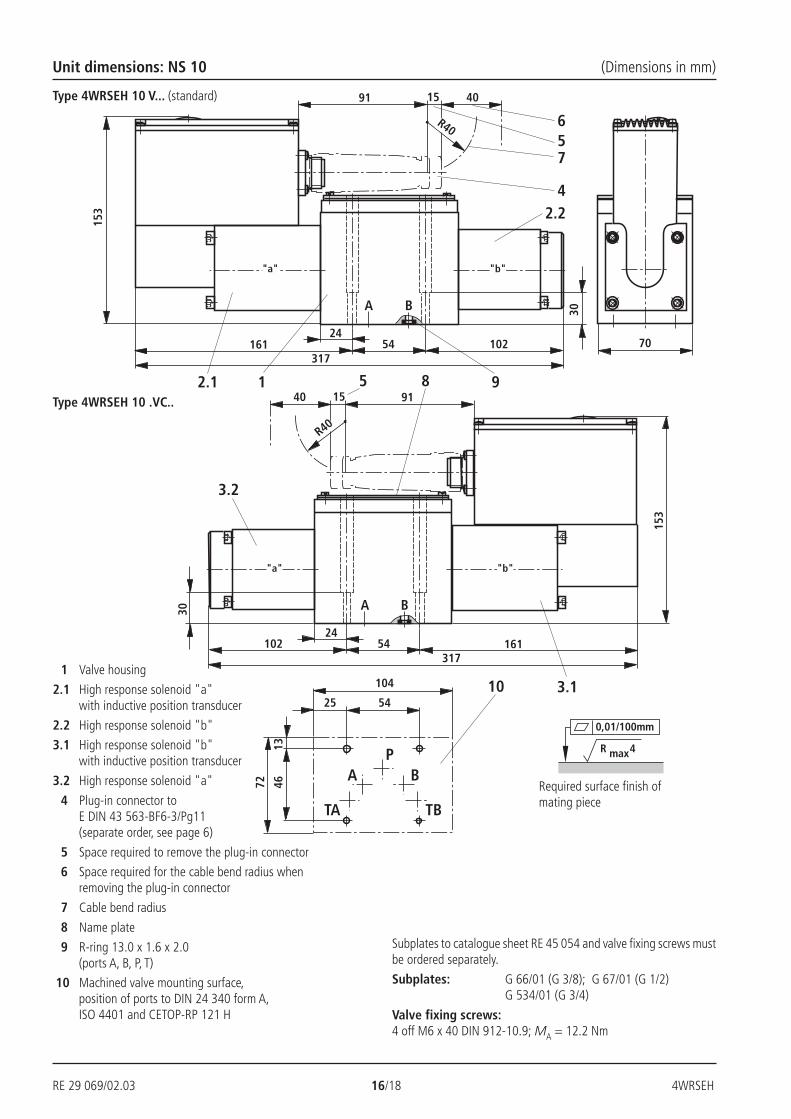
Required surface finish ofmating piece
Unit dimensions: NS 10 (Dimensions in mm)
Type 4WRSEH 10 V... (standard)
Type 4WRSEH 10 .VC..
1 Valve housing
2.1 High response solenoid "a"with inductive position transducer
2.2 High response solenoid "b"
3.1 High response solenoid "b"with inductive position transducer
3.2 High response solenoid "a"
4 Plug-in connector toE DIN 43 563-BF6-3/Pg11(separate order, see page 6)
5 Space required to remove the plug-in connector
6 Space required for the cable bend radius whenremoving the plug-in connector
7 Cable bend radius
8 Name plate
9 R-ring 13.0 x 1.6 x 2.0(ports A, B, P, T)
10 Machined valve mounting surface,position of ports to DIN 24 340 form A,ISO 4401 and CETOP-RP 121 H
Subplates to catalogue sheet RE 45 054 and valve fixing screws mustbe ordered separately.
Subplates: G 66/01 (G 3/8); G 67/01 (G 1/2)G 534/01 (G 3/4)
Valve fixing screws:4 off M6 x 40 DIN 912-10.9; MA = 12.2 Nm
4WRSEH 17/18 RE 29 069/02.03
0,01/100mm
R 4max
70
10
PA B
TA TB
104
5425
72 4613
B
"b""a"
911540
R4030
153
1615424
A
6
5
7
4
82
3.2
9 251
1 3.1
Required surface finish ofmating piece
Unit dimensions: NS 10 (Dimensions in mm)
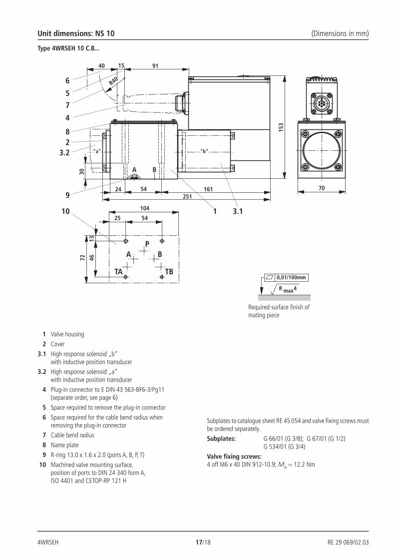
Type 4WRSEH 10 C.B...
1 Valve housing
2 Cover
3.1 High response solenoid „b“with inductive position transducer
3.2 High response solenoid „a“with inductive position transducer
4 Plug-in connector to E DIN 43 563-BF6-3/Pg11(separate order, see page 6)
5 Space required to remove the plug-in connector
6 Space required for the cable bend radius whenremoving the plug-in connector
7 Cable bend radius
8 Name plate
9 R-ring 13.0 x 1.6 x 2.0 (ports A, B, P, T)
10 Machined valve mounting surface,position of ports to DIN 24 340 form A,ISO 4401 and CETOP-RP 121 H
Subplates to catalogue sheet RE 45 054 and valve fixing screws mustbe ordered separately.
Subplates: G 66/01 (G 3/8); G 67/01 (G 1/2)G 534/01 (G 3/4)
Valve fixing screws:4 off M6 x 40 DIN 912-10.9; MA = 12.2 Nm

RE 29 069/02.03 18/18 4WRSEH
Bosch Rexroth AGIndustrial Hydraulics
D-97813 Lohr am MainZum Eisengießer 1 • D-97816 Lohr am MainTelefon 0 93 52 / 18-0Telefax 0 93 52 / 18-23 58 • Telex 6 89 418-0eMail [email protected] www.boschrexroth.de
The data specified above only serves to describethe product. No statements concerning a certaincondition or suitability for a certain applicationcan be derived from our information.The details stated do not release you from theresponsibility for carrying out your ownassessment and verification. It must beremembered that our products are subject to anatural process of wear and ageing.
Bosch Rexroth Limited
Cromwell Road, St Neots,Cambs, PE19 2ESTel: 0 14 80/22 32 56Fax: 0 14 80/21 90 52eMail: [email protected]
Notes

4WRSEH 19/18 RE 29 069/02.03
Bosch Rexroth AGIndustrial Hydraulics
D-97813 Lohr am MainZum Eisengießer 1 • D-97816 Lohr am MainTelefon 0 93 52 / 18-0Telefax 0 93 52 / 18-23 58 • Telex 6 89 418-0eMail [email protected] www.boschrexroth.de
The data specified above only serves to describethe product. No statements concerning a certaincondition or suitability for a certain applicationcan be derived from our information.The details stated do not release you from theresponsibility for carrying out your ownassessment and verification. It must beremembered that our products are subject to anatural process of wear and ageing.
Bosch Rexroth Limited
Cromwell Road, St Neots,Cambs, PE19 2ESTel: 0 14 80/22 32 56Fax: 0 14 80/21 90 52eMail: [email protected]
Notes

RE 29 069/02.03 20/18 4WRSEH
Bosch Rexroth AGIndustrial Hydraulics
D-97813 Lohr am MainZum Eisengießer 1 • D-97816 Lohr am MainTelefon 0 93 52 / 18-0Telefax 0 93 52 / 18-23 58 • Telex 6 89 418-0eMail [email protected] www.boschrexroth.de
The data specified above only serves to describethe product. No statements concerning a certaincondition or suitability for a certain applicationcan be derived from our information.The details stated do not release you from theresponsibility for carrying out your ownassessment and verification. It must beremembered that our products are subject to anatural process of wear and ageing.
Bosch Rexroth Limited
Cromwell Road, St Neots,Cambs, PE19 2ESTel: 0 14 80/22 32 56Fax: 0 14 80/21 90 52eMail: [email protected]
Notes


