New Intrinsically Safe Acoustic Emission Sensor System
for Use on Tank Ships
Hartmut VALLEN 1, Thomas THENIKL
1
1 Vallen Systeme GmbH, Icking, Germany, Phone +49 8178 9674400, [email protected]
Abstract
The oil and gas industry is a very prospective target group for the permanent installation of acoustic emission
(AE) instrumentation for monitoring various test objects for crack growth or active corrosion. According to
directives and standards, electrical instrumentation permanently installed in a potentially explosive atmosphere
must be certified intrinsically safe. The development and certification process of intrinsically safe
instrumentation needs a great effort, which is not economical for the relatively small market for intrinsically safe
AE instrumentation, nowadays. On the other hand, the non-availability of suitable intrinsically safe AE
instrumentation could be a hindrance for the potential market growth. European Commission helps to overcome
the problem: In the European research project titled "Cost effective corrosion and fatigue monitoring for
transport products (CORFAT)" (www.corfat.eu), the German company Vallen Systeme GmbH is responsible for
development and certification of an intrinsically safe AE sensor system (ISAFE3). The ISAFE3 system is
designed for detection of corrosion and fatigue cracks in all kind of tanks on ships, and for many other
applications. ISAFE3 is ATEX certified for use in most dangerous explosion zone 0 (e.g. inside a tank, above a
flammable liquid) and for gas group IIC (where lowest spark energy can ignite an explosion, e.g. hydrogen). The
sensor must resist and be sealed for immersion into oil at peak pressure up to 12 bar (caused by e.g. sloshing
forces in an oil tanker).
This paper presents basics about the requirements of the applicable standards and the applications and an
overview of the realization of ISAFE3.
Keywords: Acoustic emission; intrinsic safety; corrosion monitoring; fatigue crack detection
1. Introduction
Today, acoustic emission testing (AT) is well established as a non-destructive testing (NDT)
method in many applications, where test objects are under mechanical load, e.g. pressure
vessels, chemical reactors, pipelines, but also racing cars, sailing masts, aerospace
components, bearings, bridges, dams, and many more.
Most of these applications are temporary tests under mechanical load that exceeds the normal
work load. The higher load is needed to stimulate crack growth or crack face rubbing, if a
flaw exists. Both occurrences emit elastic waves called acoustic emissions (AE).
In recent years, needs came up for permanent monitoring of test objects. As it turns out, AE
testing is the only NDT method which can be applied cost effective 24 hours a day, 7 days a
week [1]. The need for permanent monitoring of objects shall be explained by the following
three examples:
A) A test object with known flaw is monitored permanently in order to warn the operator
when the flaw is growing.
B) In case of tank floor testing for detecting leakage or active corrosion, external conditions
like wind, temperature change, traffic, etc., influence the acoustic behaviour and may cause
incorrect testing results and false alarms. Additionally, AE activity caused by corrosion
depends also on the composition of the storage medium, which in some cases may change
over time and is out of control of an operator. With a permanently installed AE system, the
30th European Conference on Acoustic Emission Testing & 7th International Conference on Acoustic Emission University of Granada, 12-15 September 2012
www.ndt.net/EWGAE-ICAE2012/
optimum time period for gathering and analysing AE data could be automatically selected and
the quality of test results improved.
C) Test applications in which the maximum mechanical load occurs at a non-predictable
moment in time. For example: existing flaws in a ship’s structure may only grow when sea is
rough, i.e. at high load regimes. Acoustic emission of these flaws can only be detected by a
permanently installed acoustic emission measurement system.
Applications concerning example C) are in the scope of the European research project "Cost
effective corrosion and fatigue monitoring for transport products" (CORFAT,
www.corfat.eu). This project lays the ground for the development of a permanent AE system
installation on tank ships, where potential locations of flaws are known. Safety could be
improved, if those locations are monitored permanently. Other test objects addressed in that
project are tank cars for road and rail.
A location, where an explosive atmosphere could occur, is called a "hazardous area". On
tanks ships, beside of a few non-hazardous rooms, all areas are classified as hazardous and
any instrumentation installed must be certified explosion proof.
In our view, the AE test market can be tremendously expanded, when suitable, certified ex-
proof instrumentation becomes available.
Within the CORFAT project, Vallen Systeme from Germany, is responsible for designing and
providing explosion proof prototype instrumentation to allow partners to validate newly
developed AE monitoring procedures e.g. for use in the hazardous area inside a crude oil
cargo tank of a tank ship.
2. Applicable Standards for intrinsically safe electrical instrumentation
used in explosion hazardous spaces
2.1 General
A complete overview of the many standards applicable for the design of instrumentation for
use in explosion hazardous areas would go beyond the scope of a conference paper.
“Understanding global explosion protection” [2] gives a good overview about global
standardization systems like
• CLASS and DIVISION system, USA (NEC) and Canada (CEC)
• CLASS and ZONE system, USA (NEC) and Canada (CEC)
• ATEX/CENELEC/IEC system, Europe and most countries world wide)
• IECEx Scheme Global Initiative
(NEC = National Electrical Code® of USA)
(CEC = Canadian Electrical Code® of Canada)
The current paper concentrates on the special requirements of an intrinsically safe AE sensor
system suitable for detecting acoustic emissions when AE-sensors are installed inside a crude
oil tank of flammable content. Such instrumentation must fulfil the highest standards put

forward by ATEX/CENELEC/IEC. Hence this paper deals only with explosive above-ground
gas atmospheres (no mines, no dust) and the protection type "intrinsic safety".
For this limited application range all mentioned systems follow the same standard: IEC
60079.
The standards of the IEC 60079-series apply for the design and installation of devices in
explosive atmospheres. IEC 60079-0 defines general requirements. IEC 60079-11 defines the
requirements on intrinsically safe instrumentation. Intrinsic safety is one of 11 different
protection types defined in 60079-0, but the only one applicable for an AE sensor located
inside a crude oil tank and connected to a cable running several 100 m through hazardous area
up to a safety-barrier in a non-hazardous area. Therefore, following sections deal with
protection type of intrinsic safety, only.
Several classifications and groupings need to be considered when selecting a suitable ex-proof
device for a certain application. These are defined in the IEC 60079-xx standard series. Fig. 1
shows an overview, where terms with green background indicate the classification of the
described intrinsically safe AE-sensor system under development.
Fig. 1 Groupings & classifications of 60079-xx series
2.2 Grouping apparatus by place of installation
An apparatus can be installed either in a mine, then it is classified Group I, or somewhere
else, then it is classified Group II.
2.3 Group II subdivisions
This classification concerns the minimum spark ignition energy needed to ignite an explosive
atmosphere. A gas atmosphere classified IIC ignites at much less energy than a gas of group
IIB or IIA. Accordingly, the design of a device must ensure that any spark that might occur
will not have enough energy to ignite an explosion. The energy values in µJ shown in Fig. 1
for each gas group correspond to the maximum electrical pulse energy allowed for
intrinsically safe circuits.
2.4 Explosion zone classification by risk of occurrence of explosive atmosphere
A hazardous area must be classified into one of three zones. An area is of zone 0, if an
explosive gas atmosphere is present continuously or for long periods of time or frequently in
time. This condition is also defined in numbers: if the cumulated presence of explosive
atmosphere is 1000 hours per year or longer, an area is rated zone 0 [2]. For example, this is
the case above an oil- or gasoline surface in a closed container. In such an environment
explosive vapour may exist continuously. Equipment used within zone 0 must fulfil
requirements defined as Equipment Protection Level (EPL) "Ga" [3] such as: The design must
assure intrinsic safety even at two simultaneous worst case faults [4]. Faults that have to be
considered are, for example, defective electronic components or short cuts that could cause
overheating or increase the spark energy.
An area is classified zone 2, if the occurrence of an explosive atmosphere is very rare,
between 1 and 10 hour per year. Equipment used within zone 2 must fulfil requirements of
EPL "Gc". The design must assure intrinsic safety without consideration of a fault.
All other areas, where an explosive atmosphere may occur, are classified zone 1. Equipment
used in zone 1 must comply with EPL "Gb". One worst case fault must be considered.
2.5 Temperature classification
This classification deals with the surface temperature that can ignite an explosive gas
atmosphere. Equipment of e.g. temperature class T6 shall never heat a surface above 80°C at
a specified maximum ambient temperature.
2.6 Classification of protection types
IEC 60079-0 defines 11 protection types. Intrinsic safety is the only protection type suitable
for an AE-sensor system that is installed inside a crude oil storage tank. Intrinsic safety means
limitation of electrical voltage, current, power and pulse energy to a safe level in any
electrical circuit inside a hazardous area. "Limitation to a safe level" means, that energy of a
spark, e.g. by a short-cut or interruption of a circuit, must be lower than required to ignite an
explosive atmosphere. Before a cable enters a hazardous area, a device in a non-hazardous
area must ensure that limitation. The sensor located in the hazardous area must also ensure by
design, that neither a hot surface, nor the possible energy of a spark can ignite the explosive
gas atmosphere.
There are three levels of intrinsic safety:
• "ia" provides EPL "Ga" and is acceptable for zone 0, 1 and 2.
• "ib" provides EPL "Gb" and is acceptable for zone 1 and 2.
• "ic" provides EPL "Gc" and is acceptable for zone 2.
For types "ia" and "ib", the different standardization systems (IEC/ATEX, NEC, CEC) are
based on same standards: The type "i" with NEC 504 and "ia" with NEC 505 and ATEX are
identical, because both are based on IEC60079-11. Both are the only acceptable protection
type of an AE-sensor system for zone 0 areas.
Type "ib" (NEC 505 and ATEX) are acceptable in zone 1 and 2 areas.
Differences concerning zone 2 are not relevant here.
3. Requirements
The sensor under development (ISAS3) shall be certified according to the European ATEX
directive for installation in zone 0 and gas group IIC. This covers the installation in zone 1
and 2 and gas groups IIB and IIA [5]. The temperature class is T6. That means that no
component surface will exceed 80 °C, even if two worst case faults exist simultaneously.
According to [2], this covers the requirements of the North American standards, too.
For a permanent installation, a sensor holding device shall be welded or bonded to the test
object. The sensor must be mounted in a reliable manner, although in case of a defect, it must
be replaceable. For a temporary installation, sensors can be fastened by use of magnetic
holders which are mechanically compatible with the permanent sensor holder.
Sensor and cable connection must be water tight (IP68), withstand crude oil and sloshing
forces causing a peak pressure of up to 12 bar.
Since the electric energy must be limited already in the cable to the sensor, a limiting device
(safety barrier) is required outside of the hazardous area. It shall be of isolating type (signal
isolator SISO3). The isolation improves the signal-to-noise ratio, particularly with long sensor
cables, by eliminating a screen-to-earth connection of the signal cable at SISO3 side. In
addition it avoids the need of inserting safety transformers between mains supply and AE
system as required by [7].
For use on a ship, the signal isolator can be installed in a non-hazardous control room but for
use on a tank car, it must be installable in the driver cabin of a tank car which is classified to
zone 2.
The signal isolator shall be powered like a standard 28V preamplifier.
4. Realization
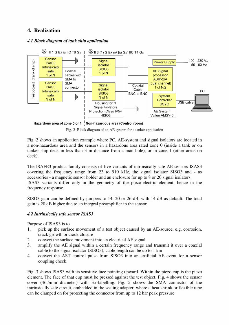
4.1 Block diagram of tank ship application
Fig. 2 Block diagram of an AE system for a tanker application
Fig. 2 shows an application example where PC, AE-system and signal isolators are located in
a non-hazardous area and the sensors in a hazardous area rated zone 0 (inside a tank or on
tanker ship deck in less than 3 m distance from a man hole), or in zone 1 (other areas on
deck).
The ISAFE3 product family consists of five variants of intrinsically safe AE sensors ISAS3
covering the frequency range from 23 to 910 kHz, the signal isolator SISO3 and - as
accessories - a magnetic sensor holder and an enclosure for up to 8 or 20 signal isolators.
ISAS3 variants differ only in the geometry of the piezo-electric element, hence in the
frequency response.
SISO3 gain can be defined by jumpers to 14, 20 or 26 dB, with 14 dB as default. The total
gain is 20 dB higher due to an integral preamplifier in the sensor.
4.2 Intrinsically safe sensor ISAS3
Purpose of ISAS3 is to
1. pick up the surface movement of a test object caused by an AE-source, e.g. corrosion,
crack growth or crack closure
2. convert the surface movement into an electrical AE signal
3. amplify the AE signal within a certain frequency range and transmit it over a coaxial
cable to the signal isolator (SISO3), cable length can be up to 1 km
4. convert the AST control pulse from SISO3 into an artificial AE event for a sensor
coupling check.
Fig. 3 shows ISAS3 with its sensitive face pointing upward. Within the piezo cup is the piezo
element. The face of that cup must be pressed against the test object. Fig. 4 shows the sensor
cover (46,5mm diameter) with Ex-labelling. Fig. 5 shows the SMA connector of the
intrinsically safe circuit, embedded in the sealing adapter, where a heat shrink or flexible tube
can be clamped on for protecting the connector from up to 12 bar peak pressure

Fig. 3 View onto piezo-cup of AE sensor ISAS3
Fig. 4 View on cover of ISAS3 with Ex-label
Fig. 5 SMA-Connector & Sealing adapter
Fig. 6 Magnetic holder MAG4IS
Fig. 7 ISAS3 on magnet holder MAG4IS
A
A
A
Piezo-cup
A A
A
3 Magnets & springs
C
C
SMA-connector
Adapter for heat shrink
hose
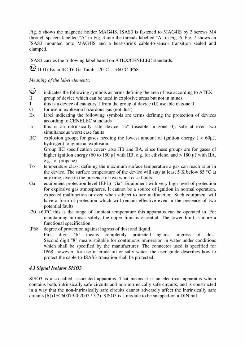
Fig. 6 shows the magnetic holder MAG4IS. ISAS3 is fastened to MAG4IS by 3 screws M4
through spacers labelled "A" in Fig. 3 into the threads labelled "A" in Fig. 6. Fig. 7 shows an
ISAS3 mounted onto MAG4IS and a heat-shrink cable-to-sensor transition sealed and
clamped.
ISAS3 carries the following label based on ATEX/CENELEC standards:
II 1G Ex ia IIC T6 Ga Tamb: -20°C ... +60°C IP68
Meaning of the label elements:
indicates the following symbols as terms defining the area of use according to ATEX
II group of device which can be used in explosive areas but not in mines
1 this is a device of category 1 from the group of device (II) useable in zone 0
G for use in explosion hazardous gas (not dust)
Ex label indicating the following symbols are terms defining the protection of devices
according to CENELEC standards
ia this is an intrinsically safe device "ia" (useable in zone 0), safe at even two
simultaneous worst case faults
IIC explosion group; for gases needing the lowest amount of ignition energy ( < 60µJ,
hydrogen) to ignite an explosion.
Group IIC specification covers also IIB and IIA, since these groups are for gases of
higher ignition energy (60 to 180 µJ with IIB, e.g. for ethylene, and > 180 µJ with IIA,
e.g. for propane)
T6 temperature class, defining the maximum surface temperature a gas can reach at or in
the device. The surface temperature of the device will stay at least 5 K below 85 °C at
any time, even in the presence of two worst case faults.
Ga equipment protection level (EPL) "Ga": Equipment with very high level of protection
for explosive gas atmospheres. It cannot be a source of ignition in normal operation,
expected malfunction or even when subject to rare malfunction. Such equipment will
have a form of protection which will remain effective even in the presence of two
potential faults.
-20..+60°C this is the range of ambient temperature this apparatus can be operated in. For
maintaining intrinsic safety, the upper limit is essential. The lower limit is more a
functional specification.
IP68 degree of protection against ingress of dust and liquid.
First digit "6" means completely protected against ingress of dust.
Second digit "8" means suitable for continuous immersion in water under conditions
which shall be specified by the manufacturer. The connector used is specified for
IP68, however, for use in crude oil or salty water, the user guide describes how to
protect the cable-to-ISAS3-transition shall be protected.
4.3 Signal Isolator SISO3
SISO3 is a so-called associated apparatus. That means it is an electrical apparatus which
contains both, intrinsically safe circuits and non-intrinsically safe circuits, and is constructed
in a way that the non-intrinsically safe circuits cannot adversely affect the intrinsically safe
circuits [6] (IEC60079-0:2007 / 3.2). SISO3 is a module to be snapped-on a DIN rail.

Fig. 8 SISO3 Module
Fig. 9 SISO3-Block Diagram
The purpose of signal isolator SISO3 is to
1.) electrically isolate the intrinsically safe sensor circuit from the AE system
2.) provide isolated DC-voltage for ISAS3 over the combined coaxial power/signal cable
3.) amplify the AE signal from the sensor and transfer it to the AE system
4.) transfer an Auto Sensor Coupling Test (AST) control pulse from the AE system to the
sensor
5.) limit the voltage, current, power and pulse energy on the intrinsically safe circuit in
accordance with EN60079-11:2007 for use in zone 0, even in the presence of two
simultaneous worst case faults in SISO3.
6.) ensure electro-static discharge of intrinsically safe cable over 220 kΩ to earth at DIN
rail, when cable is interrupted.
SISO3 carries the following label based on ATEX/CENELEC standards:
II 3 (1) G, Ex nA [ia Ga] IIC T4 Gc Tamb: -20°C ... +60°C IP30
Meaning of the label elements:
see ISAS3
II see ISAS3
3 this apparatus is of category 3 useable in zone 2 (or in non-hazardous area)
(1) this is an associated apparatus for a device of category 1 which is useable in zone 0
G for use in explosion hazardous gas (not dust)
Ex Label indicating the following symbols are terms defining the protection of devices
according to CENELEC standards
nA this is a non-sparking apparatus for use in zone 2
[ia Ga] this is an associated apparatus of an intrinsically safe device "ia" and in accordance
with Equipment Protection Level (EPL) Ga
IIC see ISAS3
T4 temperature class, defining that the maximum surface temperature a gas can reach in
this apparatus stays always below 135 °C, even in presence of two worst case faults.
Gc Equipment for explosive gas atmospheres, having a normal level of protection, which
is not a source of ignition in normal operation. That means, SISO3 can be located in
zone 2 or non-hazardous area
-20...+60°C this is the range of ambient temperature this apparatus can be operated in
IP30 degree of protection against ingress of dust and liquid according to EN60529.
First digit "3" means protected against objects larger than 2.5 mm diameter.
Second digit "0" means no protection against ingress of water
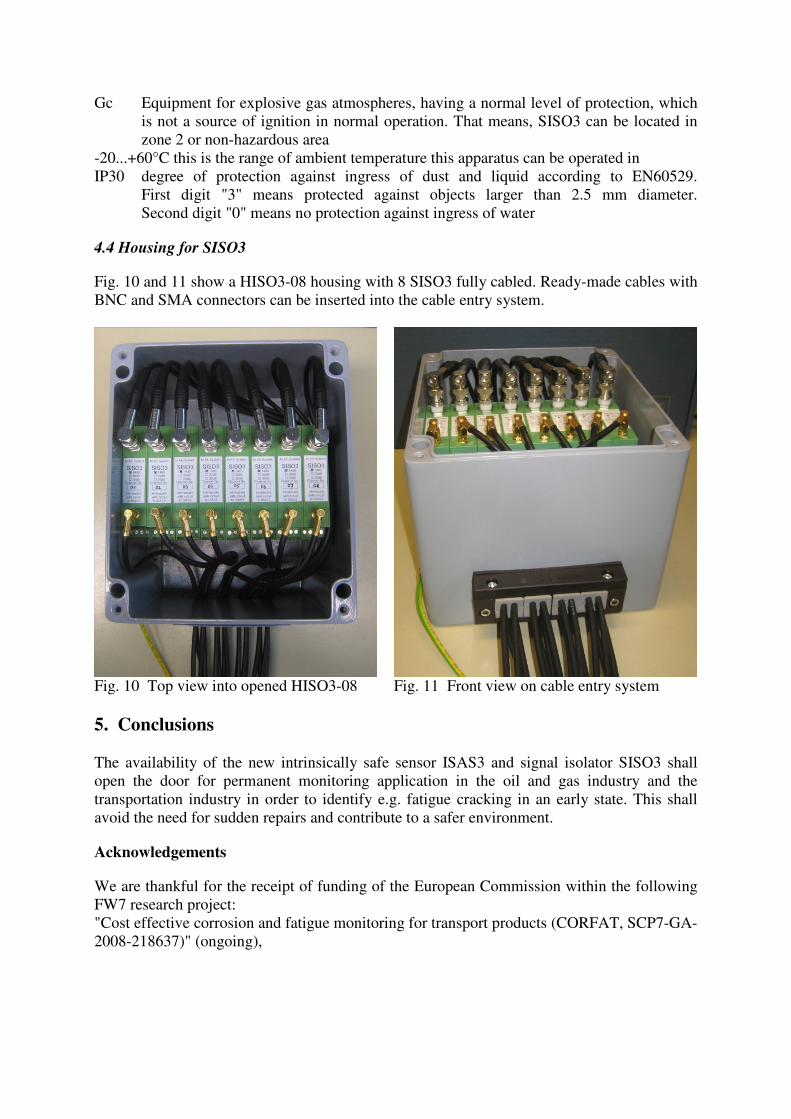
4.4 Housing for SISO3
Fig. 10 and 11 show a HISO3-08 housing with 8 SISO3 fully cabled. Ready-made cables with
BNC and SMA connectors can be inserted into the cable entry system.
Fig. 10 Top view into opened HISO3-08
Fig. 11 Front view on cable entry system
5. Conclusions
The availability of the new intrinsically safe sensor ISAS3 and signal isolator SISO3 shall
open the door for permanent monitoring application in the oil and gas industry and the
transportation industry in order to identify e.g. fatigue cracking in an early state. This shall
avoid the need for sudden repairs and contribute to a safer environment.
Acknowledgements
We are thankful for the receipt of funding of the European Commission within the following
FW7 research project:
"Cost effective corrosion and fatigue monitoring for transport products (CORFAT, SCP7-GA-
2008-218637)" (ongoing),
References
[1] C. Allevato: The use of acoustic emission testing on long term monitoring of damaged
components, EWGAE 2010 [2] R. Stahl: Understanding global explosion protection
http://www.rstahl.com/fileadmin/Dateien/tgus/Documents/StahlCatalog.pdf Pages A to A14 [3] IEC 60079-14:2007 Explosive atmospheres – Part 14: Electrical installations design,
selection and erection, Table 1. [4] IEC 60079-11:2006 Explosive atmospheres – Part 11: Equipment protection by intrinsic
safety "I", 5.2. [5] IEC 60079-0:2007 Explosive atmospheres – Part 0: Equipment requirements, 4.2 [6] IEC 60079-11:2006 Explosive atmospheres – Part 11: Equipment protection by intrinsic
safety "I". [7] IEC 60079-14:2007 Explosive atmospheres – Part 14: Electrical installations design,
selection and erection, Chapter 12.3., 4th
para.


