
M2794.007700 Smart Materials and Design
School of Mechanical and Aerospace Engineering Seoul National University
http://[email protected]
Nano Composite and
Green Composite
1
June 01, 2017
Prof. Sung-Hoon Ahn (安成勳)
© Sung-Hoon Ahn
Nano composite and green composite
▪ Nano Composite
▪ Green Composite
▪ Bio Composite
“There’s plenty of room at the bottom”Richard Feynman
2
© Sung-Hoon Ahn
Introduction
3

© Sung-Hoon Ahn
Introduction
▪ Matrix material
▪ Metal matrix composite
▪ Ceramic matrix composite
▪ Polymer matrix composite
▪ Reinforcement material
▪ Fibrous-reinforced composite
▪ particulate-reinforced composite
▪ Nano particulate-reinforced composite
▪ Nanoparticle-reinforced composite
▪ Nanofiber-reinforced composite
▪ Nanoplatelet-reinforced composite
4

© Sung-Hoon Ahn 5
What are Nano composites
▪ A nanocomposite is a composite material, in which one of the
components has at least one dimension that is around 10-9 m
Or
▪ A nanocomposite is as a multiphase solid material where one of
the phases has one, two or three dimensions of less than 100 nm,
or Structures having nano-scale repeat distances between the
different phases that make up the material.
Kamigaito (1994)

© Sung-Hoon Ahn 6
Classification of nanocomposites
▪ Polymer based
▪ Polymer/ceramic nanocomposites
▪ Inorganic/organic polymer nanocomposites
▪ Inorganic/organic hybrid nanocomposites
▪ Polymer/layered silicate nanocomposites
▪ Polymer/polymer nanocomposites
▪ Biocomposites, Eg. Elastin-collagen
▪ Non-polymer based
▪ Metal/Metal nanocomposites, Eg. Pt-Ru
▪ Metal/ceramic nanocomposites, Eg. Polysilazane/polysiloxane
▪ Ceramic/ceramic nanocomposites, Eg. Zirconia-toughened alumina
Kamigaito (1994)
© Sung-Hoon Ahn
Nanoclay properties
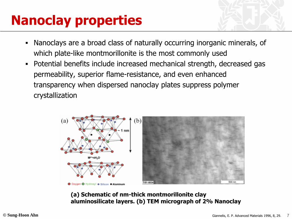
▪ Nanoclays are a broad class of naturally occurring inorganic minerals, of
which plate-like montmorillonite is the most commonly used
▪ Potential benefits include increased mechanical strength, decreased gas
permeability, superior flame-resistance, and even enhanced
transparency when dispersed nanoclay plates suppress polymer
crystallization
7
(a) Schematic of nm-thick montmorillonite clay aluminosilicate layers. (b) TEM micrograph of 2% Nanoclay
Giannelis, E. P. Advanced Materials 1996, 8, 29.

© Sung-Hoon Ahn
Graphite properties
▪ Layered, planar structure
▪ High melting point above 1650℃, similar to that of diamond
▪ Be insoluble in water as well as other organic solvents
▪ Be a good conductor of electricity
8http://chemistrycarbons.blogspot.kr/2012/11/explanation-on-structure-of-graphite.html

© Sung-Hoon Ahn
Nanotube properties
▪ Superior stiffness and strength to all other materials
▪ Extraordinary electric properties
▪ Reported to be thermally stable in a vacuum up to 2800℃ (and we fret
over CPU temps over 50℃)
▪ Capacity to carry an electric current 1000 times better than copper wires
▪ Twice the thermal conductivity of diamonds
▪ Pressing or stretching nanotubes can change their electrical properties by
changing the quantum states of the electrons in the carbon bonds
▪ They are either conducting or semi-conducting depending on the their
structure
9http://www.pa.msu.edu/cmp/csc/simindex.html
Carbon based nanotubes

© Sung-Hoon Ahn
Graphene properties
▪ Mechanical Strengths
▪ Bond length is .142 nm long = very strong bond
▪ High Young’s modulus (~1,100 Gpa);high fracture strength (125 Gpa)
▪ Strongest material ever measured, some 200 times stronger than
structural steel
▪ Very light at 0.77 milligrams per square meter, paper is 1000 times
heavier
▪ Single sheet of graphene can cover a whole football field while weighing
under 1 gram
▪ Also, graphene is very flexible, yet brittle (preventing structural use)
10http://upload.wikimedia.org/wikipedia/commons/thumb/9/9e/Graphen.jpg/750px-Graphen.jpg

© Sung-Hoon Ahn
Bucky Ball properties
▪ Arranged in pentagons and hexagons
▪ A one atom thick separation of two spaces; inside the ball and outside
▪ Highest tensile strength of any known 2D structure or element, including
cross-section of diamonds which have the highest tensile strength of all
known 3D structures (which is also a formation of carbon atoms)
▪ Also has the highest packing density of all known structures (including
diamonds)
▪ Impenetrable to all elements under normal circumstances, even a helium
atom with an energy of 5eV (electron Volt)
11
Bucky Ball (C60) C240 colliding with C60 at 300 eV
http://www.pa.msu.edu/cmp/csc/simindex.html

© Sung-Hoon Ahn
Nano-fillers used in this study
- 1 dimensional structure- High mechanical strength- High electrical- Expensive
- 2 dimensional structure- Layered structure- Good mechanical property
- 2 dimensional structure- Layered structure- Good electrical conductivity - High EMI shielding ability
Nano-clay Carbon nanotubeExfoliated graphene
nanoplates
Kim, M.S., Yan, J., Joo, K. H., Pandey, J.K., Kang, Y. J., and Ahn, S.H., 2013, "Synergistic Effects of Carbon Nanotubes and Exfoliated Graphite Nanoplatelets for Electromagnetic Interference Shielding and Soundproofing," Journal of Applied Polymer Science, Vol 130, No. 6
12

© Sung-Hoon Ahn
Nano-carbon particulate
▪ Nanoparticle-reinforced composites
▪ Carbon black (CB)
▪ Nanofiber-reinforced composites
▪ Carbon-nanofiber (CNF)
▪ Carbon-nanotube (CNT)
▪ Nanoplatelet-reinforced composites
▪ Graphite nanoplatelet (GNP)
CB
CNT CNF
GNP
13

© Sung-Hoon Ahn
GNP Functionalization
▪ Functionalization for carbon
▪ Nitric acid oxidation
▪ Immerse GNPs in HNO3 at 100°C for 30 minute
+
+14
© Sung-Hoon Ahn
GNP/epoxy composite manufacture
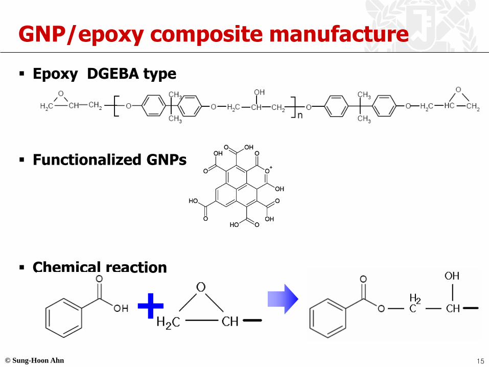
▪ Epoxy DGEBA type
▪ Functionalized GNPs
▪ Chemical reaction
+15
© Sung-Hoon Ahn
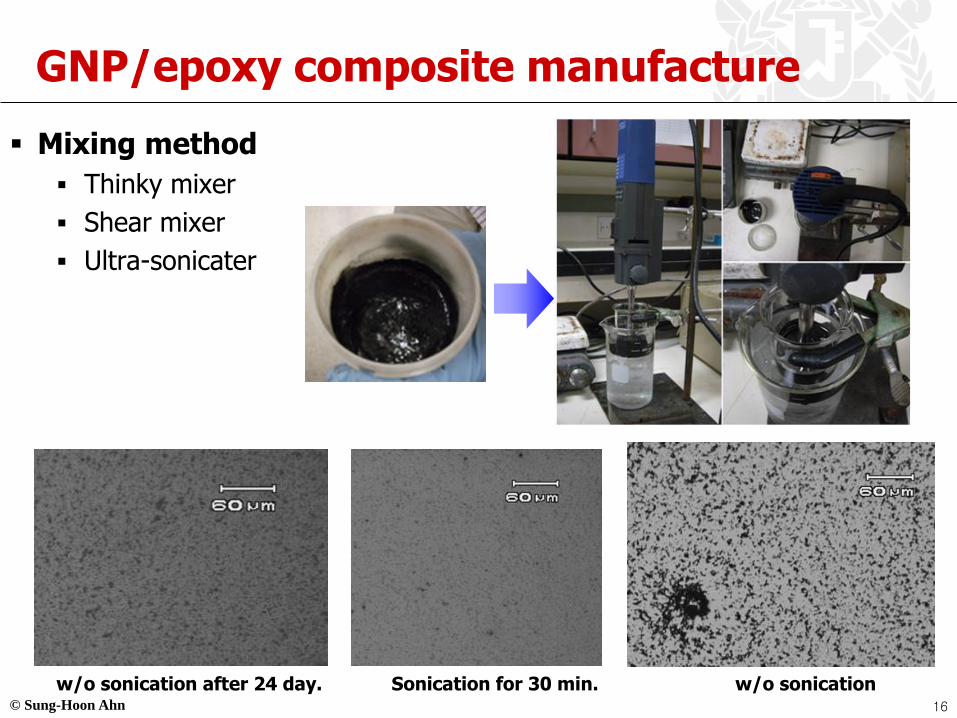
GNP/epoxy composite manufacture
▪ Mixing method
▪ Thinky mixer
▪ Shear mixer
▪ Ultra-sonicater
w/o sonication after 24 day. Sonication for 30 min. w/o sonication16

© Sung-Hoon Ahn
Mechanical property
▪ Tensile property
▪ Functionalized GNP composite’s properties are better than GNP
composite’s properties.
30%50%
17

© Sung-Hoon Ahn
Soundproofing Effect
18

© Sung-Hoon Ahn
Electromagnetic pollutionSource : ask.nate.comNoise pollution
WE
Stress Unhealthy
Soundproofing materials
Research
Source : E-Song EMC Products Guide
Electromagnetic materials
Research
Noise & Electromagnetic pollution
Automotive
Electronics
Application
Application
Thinking : Let’s solve both problems
simultaneously.
19
© Sung-Hoon Ahn
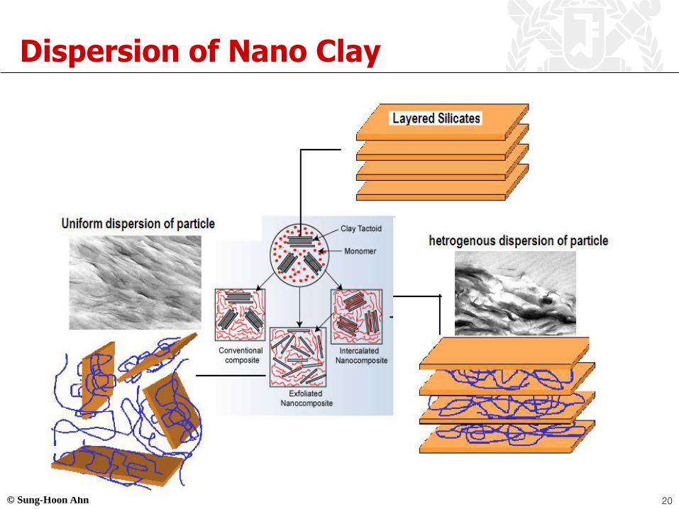
Dispersion of Nano Clay
20
© Sung-Hoon Ahn
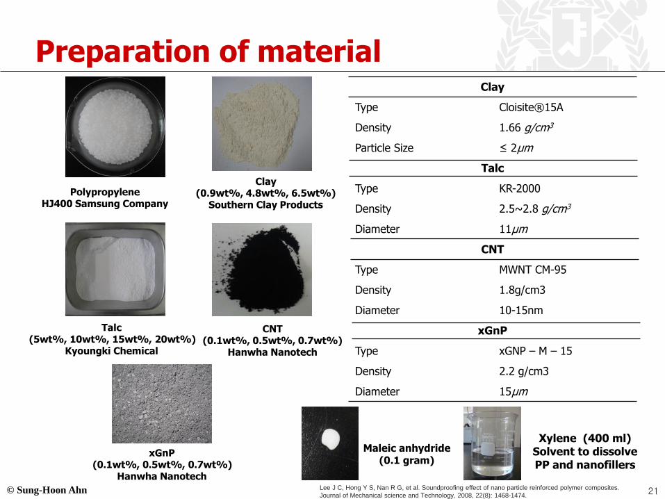
Polypropylene HJ400 Samsung Company
Clay (0.9wt%, 4.8wt%, 6.5wt%)
Southern Clay Products
Talc (5wt%, 10wt%, 15wt%, 20wt%)
Kyoungki Chemical
Clay
Type Cloisite® 15A
Density 1.66 g/cm3
Particle Size ≤ 2μm
Talc
Type KR-2000
Density 2.5~2.8 g/cm3
Diameter 11μm
CNT
Type MWNT CM-95
Density 1.8g/cm3
Diameter 10-15nm
xGnP
Type xGNP – M – 15
Density 2.2 g/cm3
Diameter 15μm
Preparation of material
CNT (0.1wt%, 0.5wt%, 0.7wt%)
Hanwha Nanotech
xGnP (0.1wt%, 0.5wt%, 0.7wt%)
Hanwha Nanotech
Maleic anhydride (0.1 gram)
Xylene (400 ml) Solvent to dissolve PP and nanofillers
21Lee J C, Hong Y S, Nan R G, et al. Soundproofing effect of nano particle reinforced polymer composites.
Journal of Mechanical science and Technology, 2008, 22(8): 1468-1474.

© Sung-Hoon Ahn
Mechanical property
Strain Gauge
▪ ASTM standard D638-03
22Yan J, Kim M S, Kang K M, et al. Evaluation of PP/Clay composites as soundproofing material.
Polymers & Polymer Composites, 2014, 22(1): 65.
© Sung-Hoon Ahn
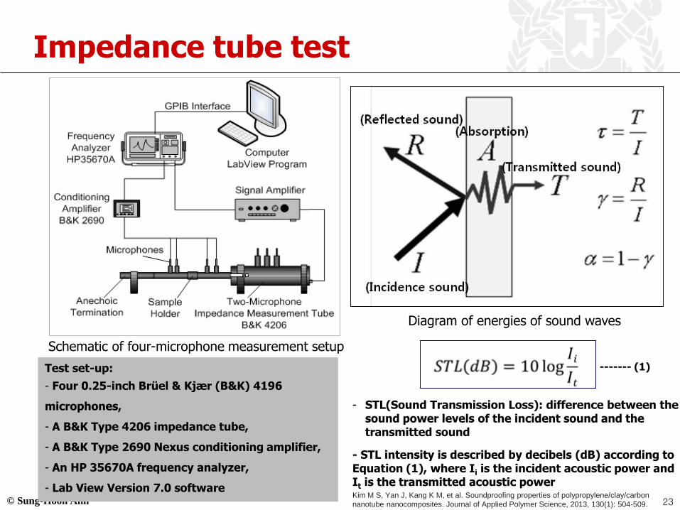
Impedance tube test
Schematic of four-microphone measurement setup
Diagram of energies of sound waves
Test set-up:
- Four 0.25-inch Brü el & Kjæ r (B&K) 4196
microphones,
- A B&K Type 4206 impedance tube,
- A B&K Type 2690 Nexus conditioning amplifier,
- An HP 35670A frequency analyzer,
- Lab View Version 7.0 software
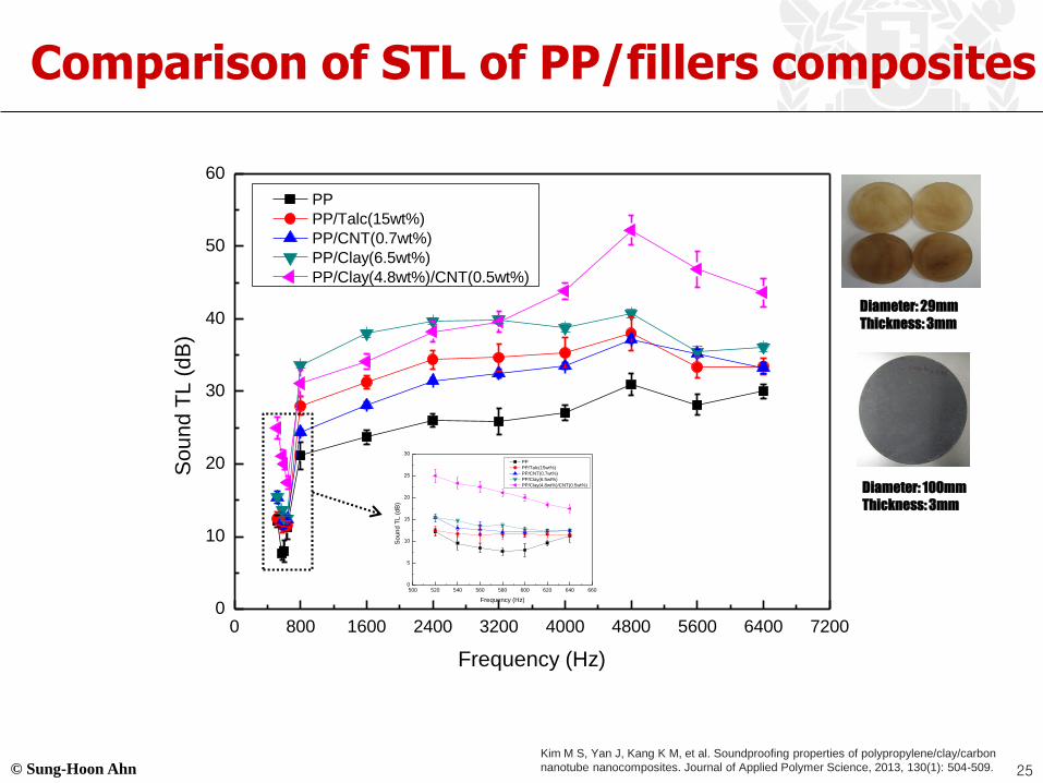
- STL(Sound Transmission Loss): difference between the sound power levels of the incident sound and the transmitted sound
- STL intensity is described by decibels (dB) according to Equation (1), where Ii is the incident acoustic power and It is the transmitted acoustic power
------- (1)
23Kim M S, Yan J, Kang K M, et al. Soundproofing properties of polypropylene/clay/carbon
nanotube nanocomposites. Journal of Applied Polymer Science, 2013, 130(1): 504-509.

© Sung-Hoon Ahn
Result
Average STL of nanoclay-reinforced PP
composites between 3400 and 4600 Hz.
24
Kim M S, Yan J, Kang K M, et al. Soundproofing properties of polypropylene/clay/carbon
nanotube nanocomposites. Journal of Applied Polymer Science, 2013, 130(1): 504-509.
© Sung-Hoon Ahn
0 800 1600 2400 3200 4000 4800 5600 6400 72000
10
20
30
40
50
60
So
un
d T
L (
dB
)
Frequency (Hz)
PP
PP/Talc(15wt%)
PP/CNT(0.7wt%)
PP/Clay(6.5wt%)
PP/Clay(4.8wt%)/CNT(0.5wt%)
500 520 540 560 580 600 620 640 6600
5
10
15
20
25
30
So
un
d T
L (
dB
)
Frequency (Hz)
PP
PP/Talc(15wt%)
PP/CNT(0.7wt%)
PP/Clay(6.5wt%)
PP/Clay(4.8wt%)/CNT(0.5wt%)
Diameter: 29mm
Thickness: 3mm
Diameter: 100mm
Thickness: 3mm
Comparison of STL of PP/fillers composites
25
Kim M S, Yan J, Kang K M, et al. Soundproofing properties of polypropylene/clay/carbon
nanotube nanocomposites. Journal of Applied Polymer Science, 2013, 130(1): 504-509.
© Sung-Hoon Ahn
EMI Shielding Effectiveness
26
© Sung-Hoon Ahn
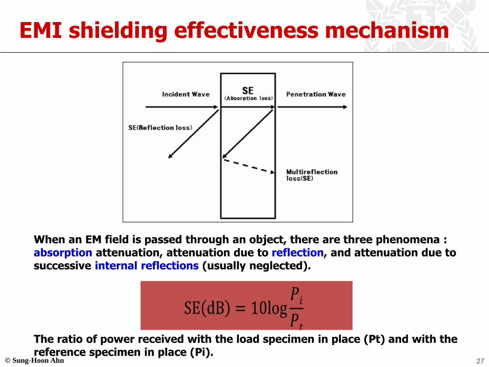
EMI shielding effectiveness mechanism
When an EM field is passed through an object, there are three phenomena : absorption attenuation, attenuation due to reflection, and attenuation due to successive internal reflections (usually neglected).
The ratio of power received with the load specimen in place (Pt) and with the reference specimen in place (Pi).
27

© Sung-Hoon Ahn
- Coaxial Transmission Line Method
- Agilent Technologies, N5230A PNA-L
Network Analyzer
- Frequency : 30MHz -1.5GHz
ASTM D 4935-99 (Diameter : 133mm, Thickness : under 1.5mm)
Measurement setup of EMI SE
28

© Sung-Hoon Ahn
Comparison of EMI SE of composites tested in this study as a function of CNT and xGnP content
- As the amount of nanofiller loading increased, EMI SE also increased
- At the same nanofiller loading, PP/CNT/xGnP nanocomposites have considerably higher
- EMI SE than other nanocomposites
■
◀
■
●
◀
●
▲
▼
0 250 500 750 1000 1250 15000
5
10
15
20
25
30
35
40
SE
(d
B)
Frequency (MHz)
PP/xGnP5
PP/xGnP10
PP/CNT5
PP/CNT10
PP/CNT5/xGnP5
PP/CNT10/xGnP10
●
▶
▼
■●▲
▼
◀
▲■
◀
▶
▶
▲
▶
29

© Sung-Hoon Ahn
Synergistic Effect of Nanocomposites
30

© Sung-Hoon Ahn
Synergistic effect of nanocomposites
Efficient property enhancement
Mechanical Electrical EMI SEThermal
Synergistic effect
Homogeneous dispersionStrong
combination
CNT
Clay
(polymer + nanofiller)
Growth of Carbon Nanotubes on Clay: Unique Nanostructured Filler for High-Performance Polymer Nanocomposites, Adv. Mater. 2006, 18, 73–7731

© Sung-Hoon Ahn
Synergistic effect of soundproofing effect
▪ Comparison of the STL values of composites
500 520 540 560 580 600 620 640 6600
5
10
15
20
25
30
So
un
d T
L (
dB
)
Frequency (Hz)
PP
PP/Talc(15wt%)
PP/CNT(0.7wt%)
PP/Clay(6.5wt%)
PP/Clay(4.8wt%)/CNT(0.5wt%)
25dB
1st place
16dB
2nd place
32

© Sung-Hoon Ahn
TEM micrographs of PP/Clay & PP/Clay/CNT composite
① Clay → dispersed homogeneously
② Good dispersion → affects property
Synergistic effect
Why good soundproofing(2nd place)?
PP/6.5wt% Clay
① Clay → dispersed homogeneously
② CNT → connected to the clay
(+ entangled and wrapped around the clay)
③ Co-network structures → affects property
Best synergistic effect
PP/4.8wt% Clay/0.5wt% CNT
Why best soundproofing(1st place)?
What mechanism?
33

© Sung-Hoon Ahn
CNT → reflect and absorb more sound
wave!
Kim, M.S., Yan, J., Joo, K. H., Pandey, J.K., Kang, Y. J., and Ahn, S.H., 2013, "Synergistic Effects of Carbon Nanotubes and Exfoliated Graphite Nanoplatelets for Electromagnetic Interference Shielding and Soundproofing," Journal of Applied Polymer Science, Vol 130, No. 6
Schematics diagram of EMI SE of nanocomposites (PP/xGnP & PP/xGnP/CNT composite)
34
© Sung-Hoon Ahn
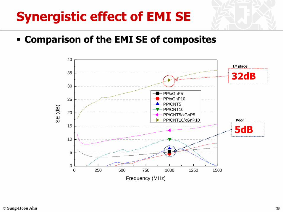
Synergistic effect of EMI SE
▪ Comparison of the EMI SE of composites
0 250 500 750 1000 1250 15000
5
10
15
20
25
30
35
40
S
E (
dB
)
Frequency (MHz)
PP/xGnP5
PP/xGnP10
PP/CNT5
PP/CNT10
PP/CNT5/xGnP5
PP/CNT10/xGnP10
●
▶
▼
■●▲
▼
◀
▲■
◀
▶ 32dB
1st place
5dB
Poor
35

© Sung-Hoon Ahn
Synergistic effect as function of filler concentration
100/0/0 99/0.9/0.1 94.7/4.8/0.5 92.8/6.5/0.70
5
10
15
20
25
30
PP/Clay/CNT (wt%)
Frequency (580Hz)
So
un
d T
L (
dB
)
▪ STL of PP/Clay/CNT as function of filler concentration
- STL value of PP/Clay/CNT increases consistently until
4.8wt% clay and 0.5wt% CNT content.
- And, then STL value decreases.
Small fillers→ few synergy
Big aggregation→ Poor synergy
Good dispersion→ strong interfacial adhesion
→ Good synergy
As the amount of filler loading increased, aggregation
of the nanofillers also increased.
36

© Sung-Hoon Ahn
Synergistic effect as function of filler concentration
100/0/0 98/1/1 96/3/3 90/5/5 86/7/7 80/10/10
0
5
10
15
20
25
30
35
40
PP/xGnP/CNT (wt%)
Frequency (1000MHz)
SE
(d
B)
▪ EMI SE of PP/xGnP/CNT as function of filler concentration
EMI SE of PP/xGnP/CNT increases
consistently with the nanofillers content.
Small fillers→ few conductive paths
Many conductive paths
37

© Sung-Hoon Ahn
Application
10-15% of total weight of the car are polymer composites.
Main merit: weight saving
Interior composite :Soundproofing materials
Need: EMI SE ability
38

© Sung-Hoon Ahn
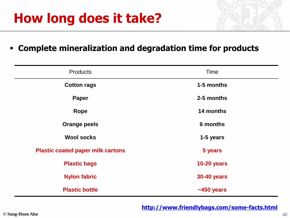
How long does it take?
▪ Complete mineralization and degradation time for products
Products Time
Cotton rags 1-5 months
Paper 2-5 months
Rope 14 months
Orange peels 6 months
Wool socks 1-5 years
Plastic coated paper milk cartons 5 years
Plastic bags 10-20 years
Nylon fabric 30-40 years
Plastic bottle ~450 years
http://www.friendlybags.com/some-facts.html40

© Sung-Hoon Ahn
Green Composites
▪ Green composite combines plant fibers with natural resins to
create natural composite materials
41
Biodegradable resin
Natural fibers
Green composites
© Sung-Hoon Ahn
Green Composites
▪ Polymer matrices
▪ Biodegradable polymers
• Natural –• Polysaccharides – Starch, Cellulose, Chitin, Pullulan…
• Proteins – Collagen/Gelatin Casein, Albumin, Fibrogen, Silks, Elastin
• Polyesters – Polyhydroxyalkanoates
• Other polymers – Lignin Natural Rubber
• Synthetic• Poly – amides /anhydrides /amide-enamines /vinyl alcohol…
▪ Fibers
• Natural /biofibers may be classified in two broad categories:
Non-wood fibers and wood fibers
• Natural fibers such as kenaf, flax, jute, hemp and sisal have attracted
interest, especially as E glass fiber substitute in the automotive industry
• Other fibers: Coir, Bamboo, Pineapple, Ramie
42
© Sung-Hoon Ahn
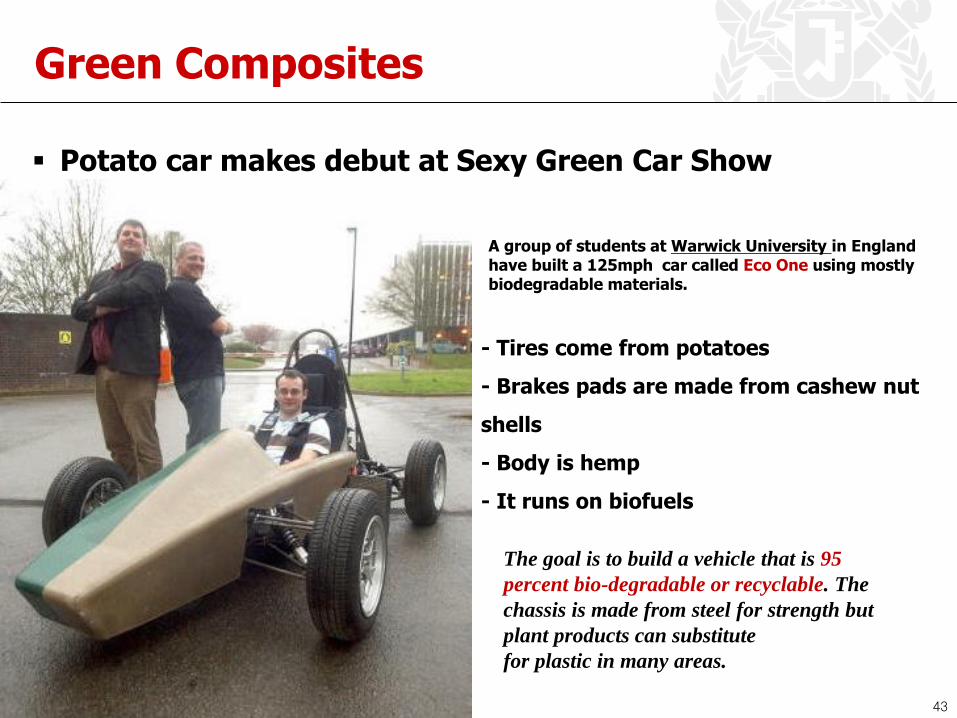
Green Composites
▪ Potato car makes debut at Sexy Green Car Show
A group of students at Warwick University in England have built a 125mph car called Eco One using mostly biodegradable materials.
- Tires come from potatoes
- Brakes pads are made from cashew nut
shells
- Body is hemp
- It runs on biofuels
The goal is to build a vehicle that is 95
percent bio-degradable or recyclable. The
chassis is made from steel for strength but
plant products can substitute
for plastic in many areas.
43
© Sung-Hoon Ahn
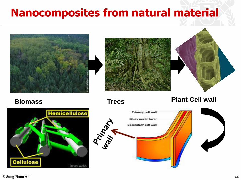
Nanocomposites from natural material
Biomass Trees Plant Cell wall
44
© Sung-Hoon Ahn
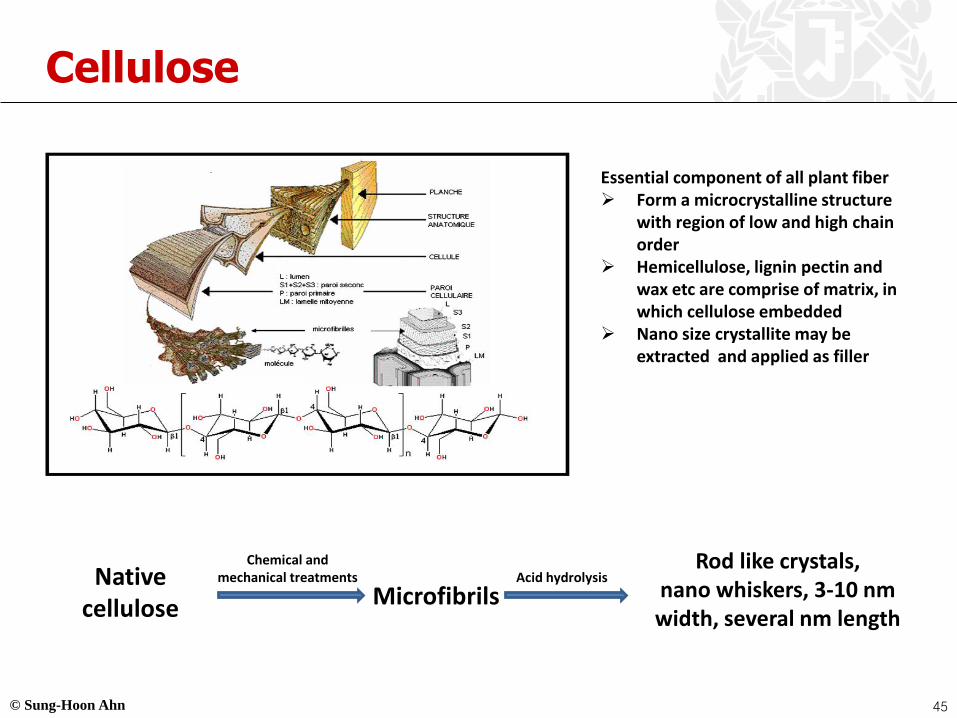
Cellulose
Essential component of all plant fiber➢ Form a microcrystalline structure
with region of low and high chain order
➢ Hemicellulose, lignin pectin and wax etc are comprise of matrix, in which cellulose embedded
➢ Nano size crystallite may be extracted and applied as filler
Native cellulose
Chemical and mechanical treatments
Microfibrils
Rod like crystals, nano whiskers, 3-10 nm width, several nm length
Acid hydrolysis
45

© Sung-Hoon Ahn
Why Nano-Cellulose
Crystalline VS Natural Vs Synthetic Fibers
Dufresne etal. J. Phys. Chem. B, 108 (2004) 10845.
46

© Sung-Hoon Ahn
Sources of Nano-Cellulose
Potato, Flax, Rice Husk, Sugar cane, wheat straw, Banana, Coconut, Bamboo
47

© Sung-Hoon Ahn
Sources of Nano-Cellulose
Korean Grass- SNU campus
Unlimited, Almost Free, No
Fertilizer, Seed requirement, deep
penetrated roots
Pandey, Ahn et.al. Macromolecular Research . 2008
48

© Sung-Hoon Ahn
Morphology of Nano-Cellulose
Pandey, Ahn et.al. e-Polymers. 2009
49
© Sung-Hoon Ahn
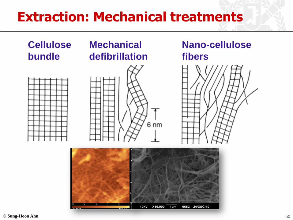
Extraction: Mechanical treatments
Cellulose
bundle
Mechanical
defibrillation
Nano-cellulose
fibers
50

© Sung-Hoon Ahn
Nanocomposites of cellulose
Optically Transparent Composites
51

© Sung-Hoon Ahn
Nanocomposites of cellulose
M.Nogi et.al. , Adv. Mater. 2009
52
© Sung-Hoon Ahn
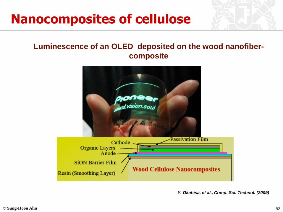
Nanocomposites of cellulose
Luminescence of an OLED deposited on the wood nanofiber-
composite
Y. Okahisa, et al., Comp. Sci. Technol. (2009)
53

© Sung-Hoon Ahn
Green Nanocomposites for Automotive Parts
Primary importance to the
automotive industry is the weight
reduction of the components,
which is possible up to 30% when using bio-fibres. ~ 20 % fuel
efficiency M. Kaup, M. Karus, ‘‘Naturfasern fu¨r die Europa¨ische Automobilindustrie’’, Nova Institute 2002, http://www.nova-institut.de
54

© Sung-Hoon Ahn
Introduction to DDS
▪ Advantages of controlled drug delivery
▪ Delivered at intended sites
▪ Less side effects
▪ Replacing multiple injection or oral DDS
▪ Improvement of patients’ quality of life
Time
Maximum
desiredlevel
Minimumeffective
level
Dose Dose Dose
Co
nce
ntr
ati
on
of
dru
g i
n t
he b
od
y
Time
Dose
Maximum
desiredlevel
Minimumeffective
levelC
on
ce
ntr
ati
on
of
dru
g i
n t
he
b
od
y
Comparison of conventional drug delivery (left) and controlled drug delivery (right)55
© Sung-Hoon Ahn
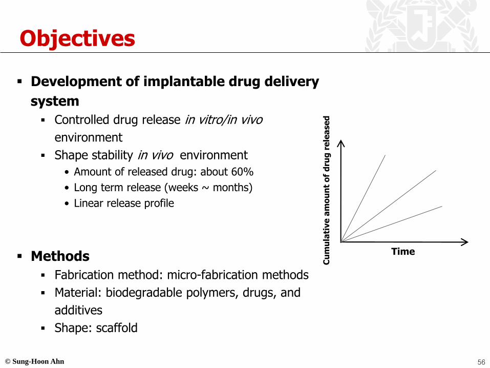
Objectives
▪ Development of implantable drug delivery
system
▪ Controlled drug release in vitro/in vivo
environment
▪ Shape stability in vivo environment
• Amount of released drug: about 60%
• Long term release (weeks ~ months)
• Linear release profile
▪ Methods
▪ Fabrication method: micro-fabrication methods
▪ Material: biodegradable polymers, drugs, and
additives
▪ Shape: scaffold
Time
Cu
mu
lati
ve
am
ou
nt
of
dru
g r
ele
ase
d
56

© Sung-Hoon Ahn
Drug-Polymer Composite
▪ Process
Ground 5-FU (about 10㎛ width)
HA particles
[-OCH(CH3)CO-]x[-OCH2CO-]y
High Shear Mixing Method in 120 ℃
ADDITIVE
POLYMER
DRUG
5-FU particle (about 100㎛width)
Matrix: PLGADL-poly(lactide-co-glycolide)
57
© Sung-Hoon Ahn
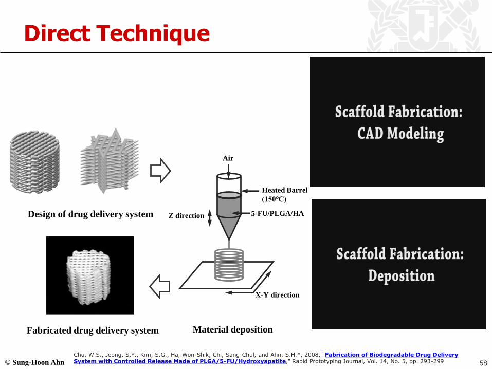
Direct Technique
Air
Heated Barrel
(150℃)
5-FU/PLGA/HAZ direction
X-Y direction
Design of drug delivery system
Fabricated drug delivery system Material deposition
Chu, W.S., Jeong, S.Y., Kim, S.G., Ha, Won-Shik, Chi, Sang-Chul, and Ahn, S.H.*, 2008, "Fabrication of Biodegradable Drug Delivery System with Controlled Release Made of PLGA/5-FU/Hydroxyapatite," Rapid Prototyping Journal, Vol. 14, No. 5, pp. 293-299 58
© Sung-Hoon Ahn
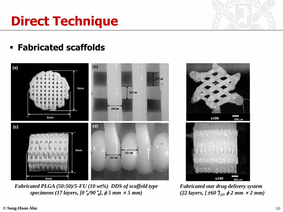
Direct Technique
▪ Fabricated scaffolds
Fabricated PLGA (50:50)/5-FU (10 wt%) DDS of scaffold type
specimens (17 layers, [0°9/90°8], 5 mm × 5 mm)
x100 250 mm
x100 250 mm
Fabricated star drug delivery system
(22 layers, [±60°]11, 2 mm × 2 mm)
59
© Sung-Hoon Ahn
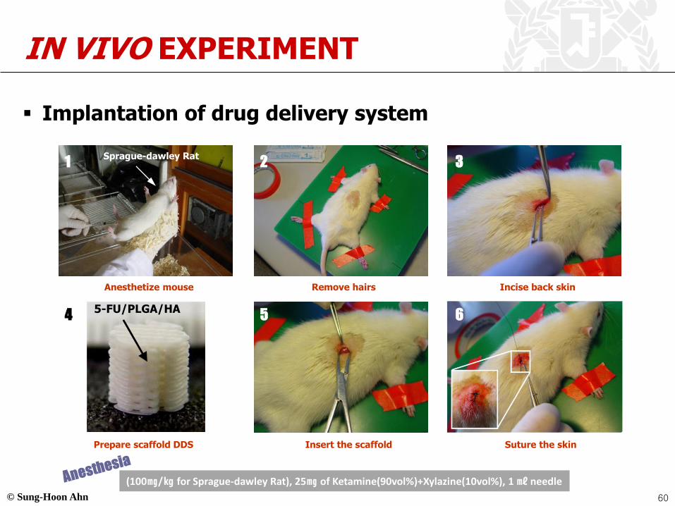
IN VIVO EXPERIMENT
▪ Implantation of drug delivery system
Remove hairs Incise back skinAnesthetize mouse
Sprague-dawley Rat
Suture the skinPrepare scaffold DDS Insert the scaffold
5-FU/PLGA/HA
(100㎎/㎏ for Sprague-dawley Rat), 25㎎ of Ketamine(90vol%)+Xylazine(10vol%), 1 ㎖ needle
1 2 3
4 5 6
60
© Sung-Hoon Ahn
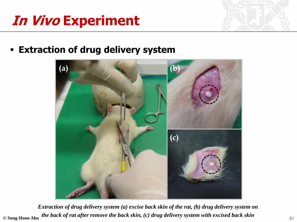
In Vivo Experiment
▪ Extraction of drug delivery system
(a) (b)
(c)
Extraction of drug delivery system (a) excise back skin of the rat, (b) drug delivery system on
the back of rat after remove the back skin, (c) drug delivery system with excised back skin61

© Sung-Hoon Ahn
In Vivo Experiment
▪ Stability of cylinder
shape scaffold
▪ 5-FU/PLGA(85:15)/HA
500 mm
500 mm
3 days 7 days 14 days
62
© Sung-Hoon Ahn
Drug Release
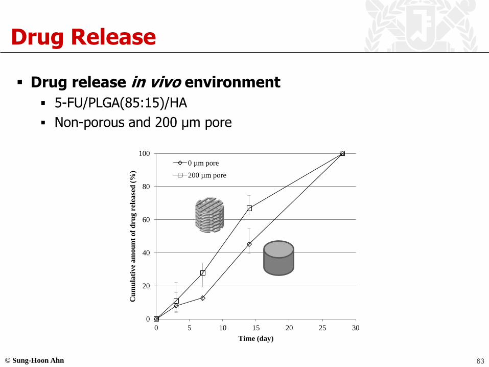
▪ Drug release in vivo environment
▪ 5-FU/PLGA(85:15)/HA
▪ Non-porous and 200 µm pore
0
20
40
60
80
100
0 5 10 15 20 25 30
Cu
mu
lati
ve
am
ou
nt
of
dru
g r
elea
sed
(%
)
Time (day)
0 µm pore
200 µm pore
63

© Sung-Hoon Ahn
Introduction to Electrochromic Window
Ref) BRIAN A. KORGEL, “Composite for smarter windows”, MATERIALS SCIENCE, NATURE, VOL 500, 15 AUGUST 2013.
33 LiWOWOeLi
(Blue)(Transparent)
▪ Electrochromic Window (ECW)
▪ Electrochromism : a reversible change in a material’s optical properties (transmittance,
absorbance and reflectance) under an applied voltage
▪ Electrochromic materials : many transition metal oxide materials, some organic molecules
and polymers
▪ Electrochromic Window : a dynamic windows allowing us to control daylight, solar heat
gain, and internal heat loss through windows of buildings and vehicles
© Sung-Hoon Ahn
Electrochromic material
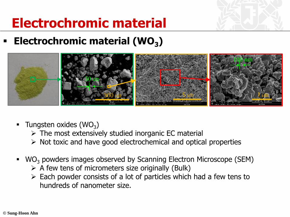
▪ Electrochromic material (WO3)
▪ Tungsten oxides (WO3) ➢ The most extensively studied inorganic EC material➢ Not toxic and have good electrochemical and optical properties
▪ WO3 powders images observed by Scanning Electron Microscope (SEM)➢ A few tens of micrometers size originally (Bulk) ➢ Each powder consists of a lot of particles which had a few tens to
hundreds of nanometer size.
300 ㎛ 5 ㎛ 1 ㎛
30 ㎛
100 nm

© Sung-Hoon Ahn
Fabrication methods of ECW
* Spray pyrolysis is in between solution and vapor base
Fabrication methods for electrochromic devicesFabrication methods trend of electrochromic devices
▪ Major processes used to deposit materials
▪ Sol-gel, Sputtering, Electrodeposition, CVD
▪ There is no dominant process for ECDs
▪ Each process has advantages and limitations.

© Sung-Hoon Ahn
Fabrication method of ECW (NPDS)
▪ Fabrication of Low-Cost ECW Using Nano Particle Deposition System (NPDS)
▪ Nano Particle Deposition System (NPDS) : WO3 particles deposition on a substrate without any precursors at room temperature and under a low vacuum condition.
▪ Easy and cost-effective process for mass production of thin films.
A schematic of NPDS for film deposition
WO3
electrolyte
ITO or FTOWO3
ITOGlass
Glass
V

© Sung-Hoon Ahn
Deposition Results – Thickness
1 ㎛
▪ The thickness of WO3
films was also measured by a SEM
▪ A cross-section image of a specimen was used
▪ The thickness of an FTO coating and WO3
film is 750 nm and 141.7 nm respectively
Glass
WO3
FTO coating
▪ Cross-section image

© Sung-Hoon Ahn
Coloring/Bleaching
▪ Required voltage : 3V(coloring), -3V(bleaching) ▪ Coloring/Bleaching time : 30 seconds
3 V30 sec
-3 V30 sec
3 V30 sec
X 3
14/17
0
20
40
60
80
100
200 400 600 800
Tra
nsm
itta
nce
[%
]
Wavelength [nm]
50%
Bleaching Coloring
FTO glass
▪ Transmittance
Park, S.I., Kim, S., Choi, J.O., Song, J.H., Ahn, S.H. and Taya, M., 2015, "Low-cost fabrication of WO3 films using a room temperature and low-vacuum air-spray based deposition system for electrochromic device applications," Thin Solid Films, Elsevier (Netherland), Vol. 589, pp. 412-418
© Sung-Hoon Ahn
Hydrogel Application
70
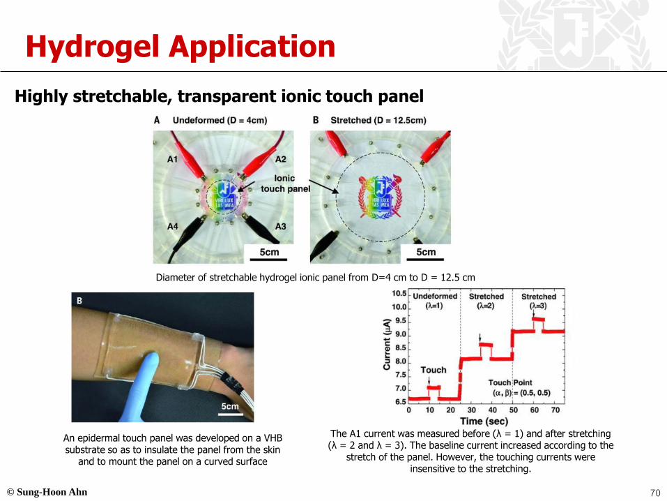
Highly stretchable, transparent ionic touch panel
An epidermal touch panel was developed on a VHB substrate so as to insulate the panel from the skin
and to mount the panel on a curved surface
Diameter of stretchable hydrogel ionic panel from D=4 cm to D = 12.5 cm
The A1 current was measured before (λ = 1) and after stretching (λ = 2 and λ = 3). The baseline current increased according to the
stretch of the panel. However, the touching currents were insensitive to the stretching.

© Sung-Hoon Ahn
Hydrogel Application
71
(Video) A tune was played using the epidermal touch panel
[Twinkle Twinkle Little Star]
(Video)Angry Birds was played by using the epidermal touch panel
[Tapping, Holding, Dragging and Swiping]


