Multiscale modeling of droplet interface bilayer membranenetworks
Eric C. Freeman,1,a) Amir B. Farimani,2 Narayana R. Aluru,2
and Michael K. Philen3
1College of Engineering, University of Georgia, Athens, Georgia 30602, USA2Department of Mechanical Science and Engineering, Beckman Institute for AdvancedScience and Technology, University of Illinois at Urbana-Champaign, Urbana,Illinois 61801, USA3Department of Aerospace and Ocean Engineering, Virginia Tech, Blacksburg,Virginia 24061, USA
(Received 31 August 2015; accepted 28 October 2015; published online 9 November 2015)
Droplet interface bilayer (DIB) networks are considered for the development of
stimuli-responsive membrane-based materials inspired by cellular mechanics.
These DIB networks are often modeled as combinations of electrical circuit ana-
logues, creating complex networks of capacitors and resistors that mimic the bio-
molecular structures. These empirical models are capable of replicating data from
electrophysiology experiments, but these models do not accurately capture the
underlying physical phenomena and consequently do not allow for simulations of
material functionalities beyond the voltage-clamp or current-clamp conditions. The
work presented here provides a more robust description of DIB network behavior
through the development of a hierarchical multiscale model, recognizing that the
macroscopic network properties are functions of their underlying molecular struc-
ture. The result of this research is a modeling methodology based on controlled
exchanges across the interfaces of neighboring droplets. This methodology is vali-
dated against experimental data, and an extension case is provided to demonstrate
possible future applications of droplet interface bilayer networks. VC 2015AIP Publishing LLC. [http://dx.doi.org/10.1063/1.4935382]
I. INTRODUCTION
In the search for new biologically inspired materials, one topic of interest is the potential
of a material based on cellular mechanics, using the controlled transport of charged ions within
a fluidic network for various applications.1 The primary inspiration for this material is the capa-
bility of cellular systems to collectively demonstrate abilities such as voltage generation,2,3 cell-
to-cell signaling,4 and complex decision making processes.5 Each of these desired abilities
requires the integrated response of multiple units working in parallel towards a common goal.
Therefore, this proposed cellular-mimicking material must effectively combine multiple units in
large interconnected arrays to best mimic natural cellular systems.
The droplet interface bilayer (DIB) technique6,7 is selected for this purpose. DIBs, developed
originally by Bayley et al.6–8 and Funakoshi et al.9 and developed further by Ces and co-
workers10,11 and Sarles and co-workers,12–15 have been considered for use as autonomous materi-
als, or stimuli-responsive materials that are capable of independently reacting to changes in their
environments. In this approach, liposome-laden aqueous droplets are deposited into oil reservoirs,
wherein the contained liposomes migrate to the oil-water interface, spreading into ordered lipid
monolayers on the droplet surfaces. Manipulating these lipid-coated droplets into contact creates
interfacial lipid bilayer membranes which approximate natural cellular membranes (Figure 1).
1932-1058/2015/9(6)/064101/14/$30.00 VC 2015 AIP Publishing LLC9, 064101-1
BIOMICROFLUIDICS 9, 064101 (2015)
This article is copyrighted as indicated in the article. Reuse of AIP content is subject to the terms at: http://scitation.aip.org/termsconditions. Downloaded to IP:
130.126.255.204 On: Mon, 09 Nov 2015 22:45:31
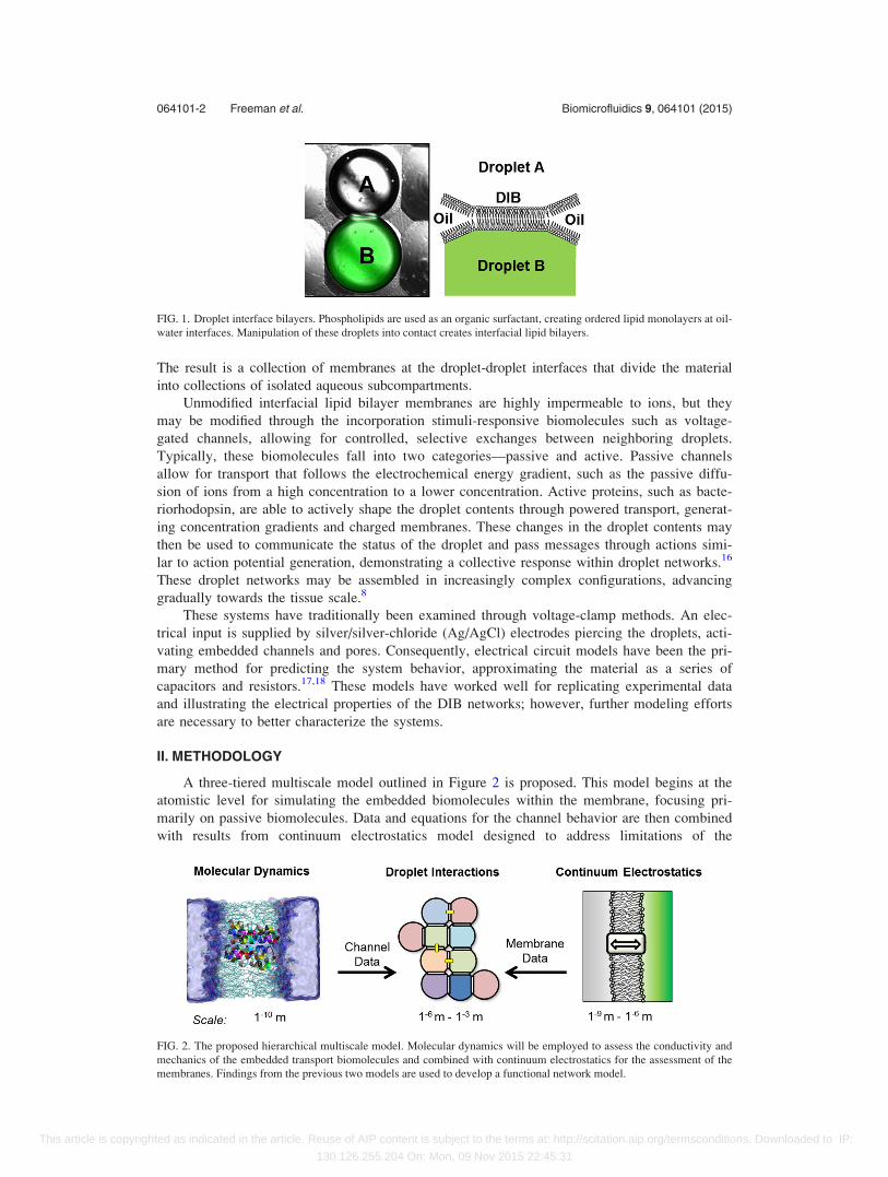
The result is a collection of membranes at the droplet-droplet interfaces that divide the material
into collections of isolated aqueous subcompartments.
Unmodified interfacial lipid bilayer membranes are highly impermeable to ions, but they
may be modified through the incorporation stimuli-responsive biomolecules such as voltage-
gated channels, allowing for controlled, selective exchanges between neighboring droplets.
Typically, these biomolecules fall into two categories—passive and active. Passive channels
allow for transport that follows the electrochemical energy gradient, such as the passive diffu-
sion of ions from a high concentration to a lower concentration. Active proteins, such as bacte-
riorhodopsin, are able to actively shape the droplet contents through powered transport, generat-
ing concentration gradients and charged membranes. These changes in the droplet contents may
then be used to communicate the status of the droplet and pass messages through actions simi-
lar to action potential generation, demonstrating a collective response within droplet networks.16
These droplet networks may be assembled in increasingly complex configurations, advancing
gradually towards the tissue scale.8
These systems have traditionally been examined through voltage-clamp methods. An elec-
trical input is supplied by silver/silver-chloride (Ag/AgCl) electrodes piercing the droplets, acti-
vating embedded channels and pores. Consequently, electrical circuit models have been the pri-
mary method for predicting the system behavior, approximating the material as a series of
capacitors and resistors.17,18 These models have worked well for replicating experimental data
and illustrating the electrical properties of the DIB networks; however, further modeling efforts
are necessary to better characterize the systems.
II. METHODOLOGY
A three-tiered multiscale model outlined in Figure 2 is proposed. This model begins at the
atomistic level for simulating the embedded biomolecules within the membrane, focusing pri-
marily on passive biomolecules. Data and equations for the channel behavior are then combined
with results from continuum electrostatics model designed to address limitations of the
FIG. 1. Droplet interface bilayers. Phospholipids are used as an organic surfactant, creating ordered lipid monolayers at oil-
water interfaces. Manipulation of these droplets into contact creates interfacial lipid bilayers.
FIG. 2. The proposed hierarchical multiscale model. Molecular dynamics will be employed to assess the conductivity and
mechanics of the embedded transport biomolecules and combined with continuum electrostatics for the assessment of the
membranes. Findings from the previous two models are used to develop a functional network model.
064101-2 Freeman et al. Biomicrofluidics 9, 064101 (2015)
This article is copyrighted as indicated in the article. Reuse of AIP content is subject to the terms at: http://scitation.aip.org/termsconditions. Downloaded to IP:
130.126.255.204 On: Mon, 09 Nov 2015 22:45:31
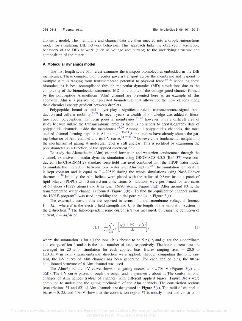
atomistic model. The membrane and channel data are then injected into a droplet-interactions
model for simulating DIB network behaviors. This approach links the observed macroscopic
behaviors of the DIB network (such as voltage and current) to the underlying structure and
composition of the material.
A. Molecular dynamics model
The first length scale of interest examines the transport biomolecules embedded in the DIB
membranes. These complex biomolecules govern transport across the membrane and respond to
multiple stimuli ranging from transmembrane potential to physical force.19–22 Modeling these
biomolecules is best accomplished through molecular dynamics (MD) simulations due to the
complexity of the biomolecular structures. MD simulations of the voltage-gated channel formed
by the polypeptide Alamethicin (Alm) channel are presented here as an example of this
approach. Alm is a passive voltage-gated biomolecule that allows for the flow of ions along
their chemical energy gradient between droplets.
Polypeptides bound to lipid bilayer play a significant role in transmembrane signal trans-
duction and cellular mobility.23,24 In recent years, a wealth of knowledge was added to litera-
ture about polypeptides that form pores in membranes;24–27 however, it is a difficult area of
study because unlike the transmembrane proteins there is no access to crystallography data of
polypeptide channels inside the membranes.28,29 Among all polypeptides channels, the most
studied channel-forming peptide is Alamethicin.30–33 Some studies have already shown the gat-
ing behavior of Alm channel and its I-V curve,24,27,34–36 however, the fundamental insight into
the mechanism of gating at molecular level is still unclear. This is rectified by examining the
pore diameter as a function of the applied electrical field.
To study the Alamethecin (Alm) channel formation and water/ion conductance through the
channel, extensive molecular dynamic simulation using GROMACS 4.5.5 (Ref. 37) were con-
ducted. The CHARMM 27 standard force field was used combined with the TIP3P water model
to simulate the interaction between ions, water, and Alm peptide.38 The simulation temperature
is kept constant and is equal to T¼ 295 K during the whole simulations using Nos�e-Hoover
thermostat.39 Initially, the Alm helices were placed with the radius of 0.8 nm inside a patch of
lipid bilayer (POPC) with 5 nm� 5 nm dimensions. Simulations were performed for two cases
of 5 helices (16729 atoms) and 6 helices (16893 atoms, Figure 3(a)). After around 80 ns, the
transmembrane water channel is formed (Figure 3(b)). To find the equilibrated channel radius,
the HOLE program40 was used, providing the initial pore radius in Figure 3(c).
The external electric fields are reported in terms of a transmembrane voltage difference
V ¼ ELz, where E is the electric field strength and Lz is the length of the simulation system in
the z direction.41 The time-dependent ionic current I(t) was measured, by using the definition of
current, I ¼ dq=dt or
I tð Þ ¼ 1
Lz
Xn
i¼1
qizi tþ dtð Þ � zi tð Þ
dt
� �; (1)
where the summation is for all the ions, dt is chosen to be 5 ps, zi and qi are the z-coordinate
and charge of ion i, and n is the total number of ions, respectively. The ionic current data are
averaged for 20 ns of simulation for each applied bias. Biases ranging from �120.0 to
120.0 mV in axial (transmembrane) direction were applied. Through computing the ionic cur-
rent, the I-V curve of Alm channel has been generated. For each applied bias, the 80 ns-
equilibrated structure of 6 Alm channel was used.
The Alm(6) bundle I-V curve shows that gating occurs at �670 mV (Figures 3(c) and
3(d)). The I-V curve passes through the origin and is symmetric about it. The conformational
changes of Alm helices (radius of channel) with different applied biases (Figure 3(c)) were
computed to understand the gating mechanism of the Alm channels. The constriction regions
(constrictions #1 and #2) of Alm channels are designated in Figure 3(c). The radii of channel at
biases¼ 0, 25, and 50 mV show that the constriction region #1 is mostly intact and constriction
064101-3 Freeman et al. Biomicrofluidics 9, 064101 (2015)
This article is copyrighted as indicated in the article. Reuse of AIP content is subject to the terms at: http://scitation.aip.org/termsconditions. Downloaded to IP:
130.126.255.204 On: Mon, 09 Nov 2015 22:45:31
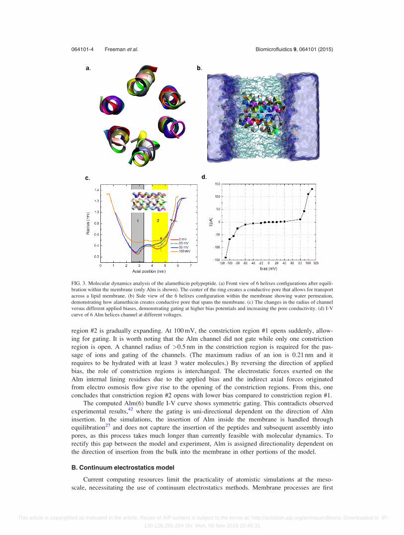
region #2 is gradually expanding. At 100 mV, the constriction region #1 opens suddenly, allow-
ing for gating. It is worth noting that the Alm channel did not gate while only one constriction
region is open. A channel radius of >0.5 nm in the constriction region is required for the pas-
sage of ions and gating of the channels. (The maximum radius of an ion is 0.21 nm and it
requires to be hydrated with at least 3 water molecules.) By reversing the direction of applied
bias, the role of constriction regions is interchanged. The electrostatic forces exerted on the
Alm internal lining residues due to the applied bias and the indirect axial forces originated
from electro osmosis flow give rise to the opening of the constriction regions. From this, one
concludes that constriction region #2 opens with lower bias compared to constriction region #1.
The computed Alm(6) bundle I-V curve shows symmetric gating. This contradicts observed
experimental results,42 where the gating is uni-directional dependent on the direction of Alm
insertion. In the simulations, the insertion of Alm inside the membrane is handled through
equilibration27 and does not capture the insertion of the peptides and subsequent assembly into
pores, as this process takes much longer than currently feasible with molecular dynamics. To
rectify this gap between the model and experiment, Alm is assigned directionality dependent on
the direction of insertion from the bulk into the membrane in other portions of the model.
B. Continuum electrostatics model
Current computing resources limit the practicality of atomistic simulations at the meso-
scale, necessitating the use of continuum electrostatics methods. Membrane processes are first
FIG. 3. Molecular dynamics analysis of the alamethicin polypeptide. (a) Front view of 6 helixes configurations after equili-
bration within the membrane (only Alm is shown). The center of the ring creates a conductive pore that allows for transport
across a lipid membrane. (b) Side view of the 6 helixes configuration within the membrane showing water permeation,
demonstrating how alamethicin creates conductive pore that spans the membrane. (c) The changes in the radius of channel
versus different applied biases, demonstrating gating at higher bias potentials and increasing the pore conductivity. (d) I-V
curve of 6 Alm helices channel at different voltages.
064101-4 Freeman et al. Biomicrofluidics 9, 064101 (2015)
This article is copyrighted as indicated in the article. Reuse of AIP content is subject to the terms at: http://scitation.aip.org/termsconditions. Downloaded to IP:
130.126.255.204 On: Mon, 09 Nov 2015 22:45:31
modeled through continuum electrostatics, and these results are combined with the atomistic
results for the final model. The continuum electrostatics model recognizes that the continuous
redistribution of charged ions is largely responsible for the experimentally observed results, and
focuses on providing a tractable methodology for studying these phenomena.
The interactions between the charged ions in solution and the developed transmembrane
potentials may be described through the Poisson equation (Equation (2)), linking the development
of the electrostatic potentials u to changes in a continuous description of the polarization q and
the dielectric permittivity e. The permittivity in the droplets is assumed to match the bulk permit-
tivity of water, as the droplet radius typically does not drop below 10 lm, eliminating constriction
effects on the permittivity.43 This electrostatics model approximates the charged ions as a contin-
uum of excess charge or polarization rather than tracking their individual trajectories
r � eru ¼ �q: (2)
Assuming negligible convection in the fluid, the flux of ions in the solution is determined
by a combination of electrical migration uzFcdu=dx and chemical diffusion Ddc=dx. Here, J is
the ion flux, u is the ion mobility, z is the valence charge, F is Faraday’s constant, c is the ion
concentration, and D is the diffusion coefficient
XJ ¼ uiziFci
dudxþ Di
dC
dx: (3)
When the net flux is zero at equilibrium, (P
J ¼ 0) these combined fluxes allow for the
derivation of the classic Boltzmann distribution. Combining this with the Poisson equation
(Equation (2)) produces the Poisson-Boltzmann distribution, appropriate for systems operating
near or at an equilibrium.44 This description is suitable for our purposes as the electrical cur-
rents are minimized by the impedance of the lipid membranes. Equation (4) is the Poisson-
Boltzmann distribution for a combination of free ions in solution and fixed lipid charges qf ixed.
Here, R is the gas constant and T is the absolute temperature
r � eru ¼ �X
ziFcbulk;i exp�ziFu
RT
� �� qf ixed: (4)
The solution of these equations with various simplifications45 allows for the derivation of
the electrical circuit analogues as functions of the droplet states, including conductivity, capaci-
tance, and chemical and electrical potentials. This approach links the observed electrical quanti-
ties and the resulting material polarization and transport, providing an electrical approximation
of the membranes based on their structure and properties.
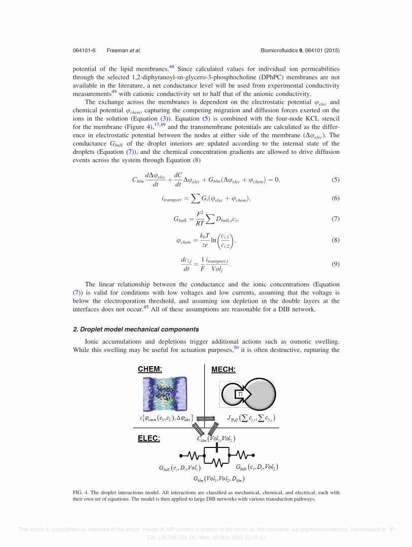
C. Droplet interactions model
A cumulative network model is developed from the two previous models, employing a
droplet-droplet interaction framework. Each droplet is defined as an entity described by a series
of values such as volume, ionic concentrations, transport biomolecules, and electrostatic poten-
tials. Differences between neighboring droplets influence their interfacial exchange of contents
and charge, gradually altering the droplet composition. The droplet interactions model is com-
bined with the electrical circuit model,17 linking the observed electrical properties with ion
migration and accumulation/depletion. A summary of the model may be seen in Figure 4.
1. Droplet model electrical components
Ion species in the system are assigned a valence charge z, bulk diffusion coefficient Dbulk,
membrane diffusion coefficient Dblm, and respective droplet molar concentrations ci. Bulk diffu-
sion coefficients are taken from experimental studies by Samson et al.46 Cation diffusion is
generally lower than anion diffusion across the membrane47 due to the positive interior dipole
064101-5 Freeman et al. Biomicrofluidics 9, 064101 (2015)
This article is copyrighted as indicated in the article. Reuse of AIP content is subject to the terms at: http://scitation.aip.org/termsconditions. Downloaded to IP:
130.126.255.204 On: Mon, 09 Nov 2015 22:45:31
potential of the lipid membranes.48 Since calculated values for individual ion permeabilities
through the selected 1,2-diphytanoyl-sn-glycero-3-phosphocholine (DPhPC) membranes are not
available in the literature, a net conductance level will be used from experimental conductivity
measurements49 with cationic conductivity set to half that of the anionic conductivity.
The exchange across the membranes is dependent on the electrostatic potential uelec and
chemical potential uchem, capturing the competing migration and diffusion forces exerted on the
ions in the solution (Equation (3)). Equation (5) is combined with the four-node KCL stencil
for the membrane (Figure 4),17,49 and the transmembrane potentials are calculated as the differ-
ence in electrostatic potential between the nodes at either side of the membrane (Duelec). The
conductance Gbulk of the droplet interiors are updated according to the internal state of the
droplets (Equation (7)), and the chemical concentration gradients are allowed to drive diffusion
events across the system through Equation (8)
CblmdDuelec
dtþ dC
dtDuelec þ Gblm Duelec þ uchemð Þ ¼ 0; (5)
itransport ¼X
Giðuelec þ uchemÞ; (6)
Gbulk ¼F2
RT
XDbulk;ici; (7)
uchem ¼kbT
zeln
ci;1
ci;2
� �; (8)
dci;j
dt¼ 1
F
itransport;i
Volj: (9)
The linear relationship between the conductance and the ionic concentrations (Equation
(7)) is valid for conditions with low voltages and low currents, assuming that the voltage is
below the electroporation threshold, and assuming ion depletion in the double layers at the
interfaces does not occur.45 All of these assumptions are reasonable for a DIB network.
2. Droplet model mechanical components
Ionic accumulations and depletions trigger additional actions such as osmotic swelling.
While this swelling may be useful for actuation purposes,50 it is often destructive, rupturing the
FIG. 4. The droplet interactions model. All interactions are classified as mechanical, chemical, and electrical, each with
their own set of equations. The model is then applied to large DIB networks with various transduction pathways.
064101-6 Freeman et al. Biomicrofluidics 9, 064101 (2015)
This article is copyrighted as indicated in the article. Reuse of AIP content is subject to the terms at: http://scitation.aip.org/termsconditions. Downloaded to IP:
130.126.255.204 On: Mon, 09 Nov 2015 22:45:31
interfacial membranes, and contributing to droplet coalescence.51 The osmotic swelling
dVoldroplet of each droplet is calculated as the summation of the osmotic flux across each of the
droplet’s interfacial membranes. This is a function of the membrane hydraulic diffusivity Kblm,
membrane area Ablm, existing hydrostatic pressure across the membrane due to varying droplet
sizes DPblm,52 and osmotic pressure p. The osmotic pressure is calculated through a summation
of the difference in bulk ion concentrations on either side of the membrane and their respective
osmotic coefficients h (assumed to be unity here). The diffusivity Kblm is adapted from studies
by Negret et al.53
dVoldroplet
dt¼Xndroplet
i
Kblm;iAblm;i
Xnion
j
pj � DPblm;i
!" #; (10)
pj ¼ RThðcj;i � cj;eÞ: (11)
3. Droplet model chemical components
The behavior of the transport biomolecules must be reduced to a more compact thermody-
namic form for the droplet-droplet model while still retaining pertinent MD information such as
conductivity and gating behavior. This requires an approach similar to the one developed by
Endresen et al.,54 calculating the rate of transport across the biomolecules through energetic
balances equating the work done by the protein to the work required to transport an ion across
the membrane55 (Equation (12))
euprotein ¼ zeðuelec þ uchemÞ: (12)
These equations must take into account multiple gating behaviors such as voltage, ligand,
and tension activation modes. This is accomplished by modifying the overall current through
the biomolecule by a gating probability xopen, which calculates the likelihood of gating based
on comparing the activation threshold to the current condition. For a voltage-activated channel
such as Alm, this may be written as54
xopen ¼1
21þ tanh
qgatee uelec � uactivateð ÞkbT
� �� �: (13)
The resulting equations for current across a transport biomolecule ibio may be written in a
general form as seen in Equation (14), multiplying the open-state conductance of the biomole-
cule Gbio by the gating probability xopen predicted by Equation (13) and some function of the
transmembrane state f . The function f is selected dependent on the available information—for
the Alm simulation presented in the following chapter; the function is simplified to a transmem-
brane potential dependent conductivity to best fit the data available from the simulations where
ibio ¼ GbioðuelecÞðuelec þ uchem þ uproteinÞ
ibio ¼ Gbioxopenfe uelec þ uchem þ uproteinð Þ
2kbT
� �: (14)
4. Solution methodology
A python script was developed to automatically generate the previous interaction equations.
Droplets are assembled into networks, and biomolecules are assigned to the shared interfacial
bilayers. Ion transport across the droplet chains is handled through a series of linked electrical
circuit equations, updating the internal values through Equations (6) and (7). Each droplet is
assigned multiple nodes at the connective bilayers, and the appropriate connections are made
with resistor and capacitor elements (Equation (5), Figure 4). The generated equations provide
064101-7 Freeman et al. Biomicrofluidics 9, 064101 (2015)
This article is copyrighted as indicated in the article. Reuse of AIP content is subject to the terms at: http://scitation.aip.org/termsconditions. Downloaded to IP:
130.126.255.204 On: Mon, 09 Nov 2015 22:45:31
a large stiff system of differential algebraic equations (DAEs) which are solved using the IDAS
solver available from Lawrence Livermore56 through the CasaDI shell.57 The end result is a
model of droplet-droplet interactions, where the internal properties of each droplet dictate the
communications across the interfacial membranes.
III. RESULTS AND DISCUSSION
A. Model validation
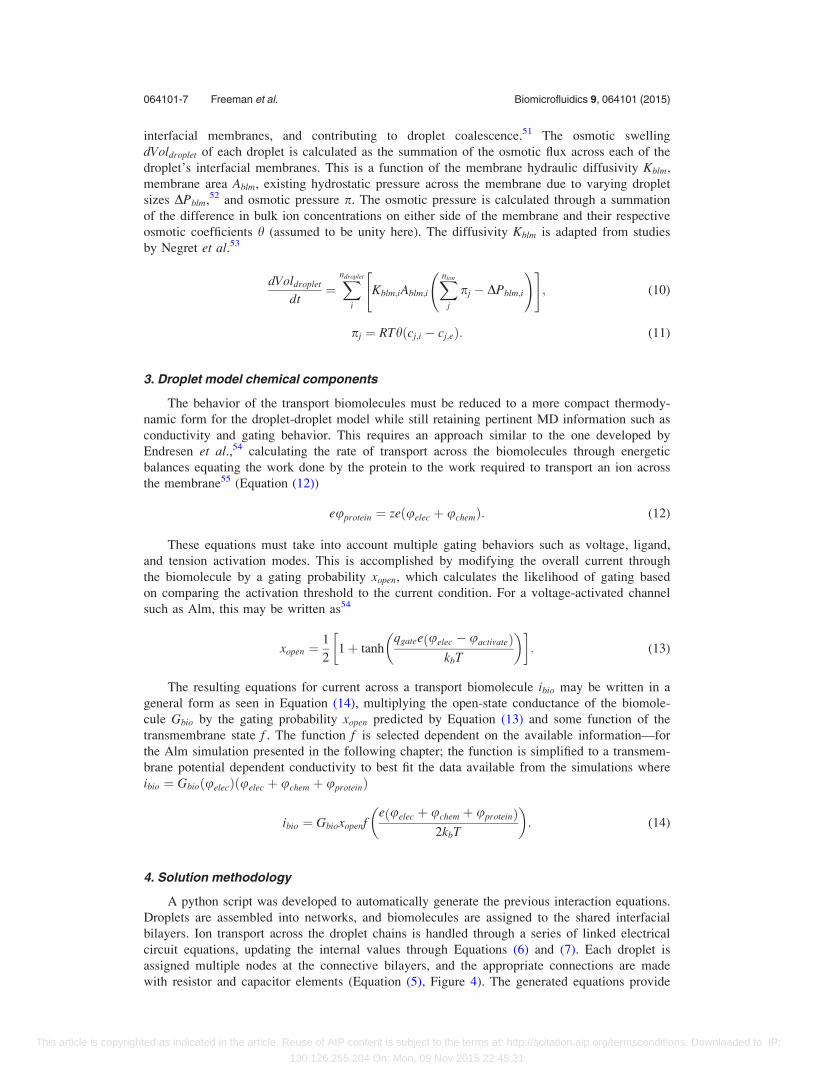
The full multiscale approach is validated by simulating a DIB network with Alm channels
and comparing to experimental results. Three droplets all containing the Alm biomolecules
(5 lg/ml) were deposited in a crate substrate in a linear chain (Figure 5(a)), allowing for a bi-
directional path of Alm channels between the source and ground. Since Alm is present in each
droplet in the network, the Alm channels were inserted in both directions in both membranes.
A 100 mV 1 Hz sinusoidal voltage was created between the electrodes. At this frequency, the
potential evenly distributes across the two membranes (similar to a voltage divider),17 allowing for
initial transmembrane potentials of 50 mV assuming uniform membrane qualities. This level of
transmembrane potential is insufficient to activate the Alm channels as shown in Figures 3(c) and
3(d), and the measured current is primarily a capacitive response to the changing transmembrane
potentials, where i ¼ Cblmduelec
dt . A 50 mV DC transmembrane potential is then combined with the
original oscillating potential, and spikes are observed for positive potentials as the redistributed
transmembrane potential reaches 75 mV at their peaks (Figure 5(e)). The experimental data were
imported into python scripts for analysis, and the current for 40 voltage cycles was averaged for
comparison with the model predictions (Figure 5(e)), smoothing the individual gating events.
The Alm channels are modeled with two conductance states observed in the MD simula-
tions (Figure 5(d)). While Alm exhibits additional gating states,49 these higher states are not
included as the required membrane potential may cause undesired membrane rupture
(�100 mV)
FIG. 5. Multiscale model validation through a simple DIB network with Alm channels. (a) Three droplets containing dis-
solved Alm biomolecules are deposited in an oil reservoir with electrodes embedded within the bordering droplets. A
100 mV sinusoidal voltage is supplied between the electrodes across the two membranes both with and without a 50 mV
DC offset, and the results for 40 cycles are averaged and plotted in (d). This simple three-droplet network is recreated using
the inputs from (b) and equations fit to the molecular dynamics simulation data in (c) and (d), and the predicted results are
compared to the experimental results in (d).
064101-8 Freeman et al. Biomicrofluidics 9, 064101 (2015)
This article is copyrighted as indicated in the article. Reuse of AIP content is subject to the terms at: http://scitation.aip.org/termsconditions. Downloaded to IP:
130.126.255.204 On: Mon, 09 Nov 2015 22:45:31

C$O1$O2: (15)
Equation (13) is modified to accommodate the multiple gating stages, and the channels are
assumed to follow the progression depicted in Equation (15), progressing from closed pores
through the two open conductance states. The resulting fit for these conductance states to the
MD data for a single channel may be seen in Figures 5(c) and 5(d). The ionic conductance of
Alm was calculated by dividing the current by the simulated voltage from Figure 3(d), and the
gating charges and thresholds were varied until a suitable match was found.
Alm exhibits some selectivity in its conductance.58 This is not considered here, as this pri-
marily influences the ion concentrations within the droplets (Equation (9)), which in turn influ-
ences the Nernst potentials (Equation (8)). Here, the droplets are large (1 mm diameter), and
any shifts in their compositions will take a long enough time to be considered negligible over
the course of the presented experiments. This is shown in Figure 7(c) as well.
The three droplet chain containing bi-directional Alm channels was recreated in the model
as seen in Figures 5(b)–5(e) and subjected to the same applied potentials. The predicted output
current matches the experimental current, exhibiting the predicted two stage gating process
from Equation (15), with a brief spike in conductivity at the peak voltages (Figure 5(e)). This
current does not follow typical Alm conductivity sweeps, as the current contains capacitive and
conductive elements to test the predictions of the model. A sinusoidal voltage sweep provides
the underlying phase-shifted sinusoidal capacitive current, and increasing the DC component of
the command signal generates the conductive spikes due to Alm gating.
B. Model extension example
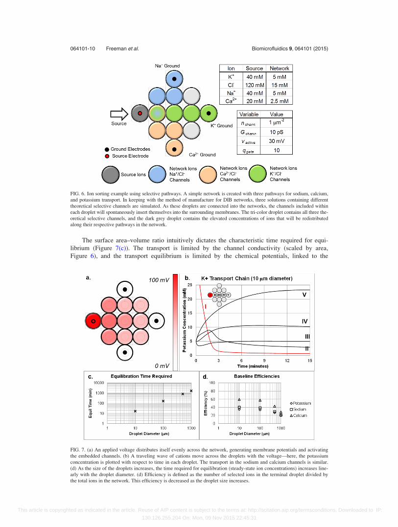
With the model validation complete, a theoretical DIB network with selective ionic path-
ways is constructed within the model to demonstrate the underlying links between the measured
electrical signals and the changes in droplet compositions. Here, theoretical ion-selective volt-
age-gated channels (representative of those commonly found in plant cells) are created and
simulated, including Kþ, Naþ, Ca2þ, and Cl� selective channels (Figure 6). Droplets containing
these channels are arranged into a network designed for sorting cations from a high-
concentration source droplet to their respective storage droplets. The channels are originally dis-
solved within the droplets, and it is assumed that these channels distribute themselves evenly
across the membranes connected to their respective droplets, resulting in a similar channels-per-
membrane value for each membrane. Three base channel solutions are included as shown in
Figure 6, with the tri-color droplet assuming an equal blend of the first three. Each solution
contains a selective channel, and these channels are assumed to populate the membranes con-
nected to each droplet. A voltage is applied across the interfacial membranes, and the embed-
ded selective channels facilitate the transport of ions along their respective pathways to the
ground electrodes.
Initial results are summarized in Figure 7. As expected, the simulated ions respond to the
applied potential (Figure 7(a)), moving from droplet to droplet along their respective chains
(Figure 7(b)). Several competing effects are observed. The transport is initially aided by the
chemical potentials (Equation (8)), but this gradually reverses and inhibits the transport across
each membrane until equilibrium is reached. At this point, the generated chemical potential bal-
ances the supplied electrical potential. Osmotic swelling is also accounted for (Equation (10)),
gradually reducing the chemical potentials through the flux of water across the membranes.
This osmotic behaviour is ultimately beneficial if the overall efficiency is defined as the
total number of moles in the storage droplets divided by the total number of moles in the net-
work, reducing the chemical energy necessary for ion transport. At first glance, this contrasts
previous observations in which the osmotic diffusion reduced the efficiency of the chemical-
electrical energy conversion;2 however, the overall mechanic remains unchanged. Osmotic flux
continuously reduces the stored chemical energy in the network, allowing for continued trans-
port when a surplus electrical energy is provided.
064101-9 Freeman et al. Biomicrofluidics 9, 064101 (2015)
This article is copyrighted as indicated in the article. Reuse of AIP content is subject to the terms at: http://scitation.aip.org/termsconditions. Downloaded to IP:
130.126.255.204 On: Mon, 09 Nov 2015 22:45:31
The surface area–volume ratio intuitively dictates the characteristic time required for equi-
librium (Figure 7(c)). The transport is limited by the channel conductivity (scaled by area,
Figure 6), and the transport equilibrium is limited by the chemical potentials, linked to the
FIG. 6. Ion sorting example using selective pathways. A simple network is created with three pathways for sodium, calcium,
and potassium transport. In keeping with the method of manufacture for DIB networks, three solutions containing different
theoretical selective channels are simulated. As these droplets are connected into the networks, the channels included within
each droplet will spontaneously insert themselves into the surrounding membranes. The tri-color droplet contains all three the-
oretical selective channels, and the dark grey droplet contains the elevated concentrations of ions that will be redistributed
along their respective pathways in the network.
FIG. 7. (a) An applied voltage distributes itself evenly across the network, generating membrane potentials and activating
the embedded channels. (b) A traveling wave of cations move across the droplets with the voltage—here, the potassium
concentration is plotted with respect to time in each droplet. The transport in the sodium and calcium channels is similar.
(d) As the size of the droplets increases, the time required for equilibration (steady-state ion concentrations) increases line-
arly with the droplet diameter. (d) Efficiency is defined as the number of selected ions in the terminal droplet divided by
the total ions in the network. This efficiency is decreased as the droplet size increases.
064101-10 Freeman et al. Biomicrofluidics 9, 064101 (2015)
This article is copyrighted as indicated in the article. Reuse of AIP content is subject to the terms at: http://scitation.aip.org/termsconditions. Downloaded to IP:
130.126.255.204 On: Mon, 09 Nov 2015 22:45:31
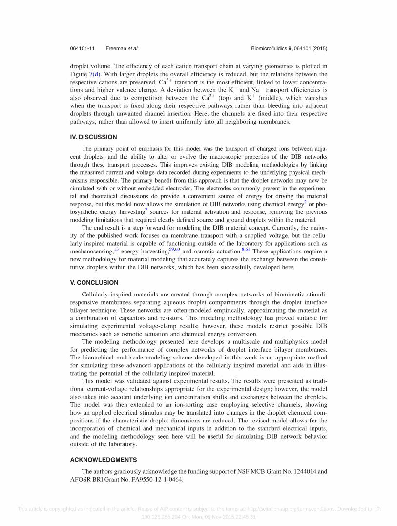
droplet volume. The efficiency of each cation transport chain at varying geometries is plotted in
Figure 7(d). With larger droplets the overall efficiency is reduced, but the relations between the
respective cations are preserved. Ca2þ transport is the most efficient, linked to lower concentra-
tions and higher valence charge. A deviation between the Kþ and Naþ transport efficiencies is
also observed due to competition between the Ca2þ (top) and Kþ (middle), which vanishes
when the transport is fixed along their respective pathways rather than bleeding into adjacent
droplets through unwanted channel insertion. Here, the channels are fixed into their respective
pathways, rather than allowed to insert uniformly into all neighboring membranes.
IV. DISCUSSION
The primary point of emphasis for this model was the transport of charged ions between adja-
cent droplets, and the ability to alter or evolve the macroscopic properties of the DIB networks
through these transport processes. This improves existing DIB modeling methodologies by linking
the measured current and voltage data recorded during experiments to the underlying physical mech-
anisms responsible. The primary benefit from this approach is that the droplet networks may now be
simulated with or without embedded electrodes. The electrodes commonly present in the experimen-
tal and theoretical discussions do provide a convenient source of energy for driving the material
response, but this model now allows the simulation of DIB networks using chemical energy2 or pho-
tosynthetic energy harvesting7 sources for material activation and response, removing the previous
modeling limitations that required clearly defined source and ground droplets within the material.
The end result is a step forward for modeling the DIB material concept. Currently, the major-
ity of the published work focuses on membrane transport with a supplied voltage, but the cellu-
larly inspired material is capable of functioning outside of the laboratory for applications such as
mechanosensing,13 energy harvesting,59,60 and osmotic actuation.8,61 These applications require a
new methodology for material modeling that accurately captures the exchange between the consti-
tutive droplets within the DIB networks, which has been successfully developed here.
V. CONCLUSION
Cellularly inspired materials are created through complex networks of biomimetic stimuli-
responsive membranes separating aqueous droplet compartments through the droplet interface
bilayer technique. These networks are often modeled empirically, approximating the material as
a combination of capacitors and resistors. This modeling methodology has proved suitable for
simulating experimental voltage-clamp results; however, these models restrict possible DIB
mechanics such as osmotic actuation and chemical energy conversion.
The modeling methodology presented here develops a multiscale and multiphysics model
for predicting the performance of complex networks of droplet interface bilayer membranes.
The hierarchical multiscale modeling scheme developed in this work is an appropriate method
for simulating these advanced applications of the cellularly inspired material and aids in illus-
trating the potential of the cellularly inspired material.
This model was validated against experimental results. The results were presented as tradi-
tional current-voltage relationships appropriate for the experimental design; however, the model
also takes into account underlying ion concentration shifts and exchanges between the droplets.
The model was then extended to an ion-sorting case employing selective channels, showing
how an applied electrical stimulus may be translated into changes in the droplet chemical com-
positions if the characteristic droplet dimensions are reduced. The revised model allows for the
incorporation of chemical and mechanical inputs in addition to the standard electrical inputs,
and the modeling methodology seen here will be useful for simulating DIB network behavior
outside of the laboratory.
ACKNOWLEDGMENTS
The authors graciously acknowledge the funding support of NSF MCB Grant No. 1244014 and
AFOSR BRI Grant No. FA9550-12-1-0464.
064101-11 Freeman et al. Biomicrofluidics 9, 064101 (2015)
This article is copyrighted as indicated in the article. Reuse of AIP content is subject to the terms at: http://scitation.aip.org/termsconditions. Downloaded to IP:
130.126.255.204 On: Mon, 09 Nov 2015 22:45:31

APPENDIX: EXPERIMENTAL
Networks of droplet interface bilayers6 were constructed using a machined acrylic-glass egg-
crate substrate, allowing the droplets to settle into predefined locations and form fluidic networks
at their points of contact.7 The substrate was CNC machined from acrylic glass (Optix,
Plaskolite), selected for its translucency and hydrophobicity. The crate substrate consists of two
portions, an oil well and a network of smaller individual crates. The liposome-containing solution
was created with a 500 mM KCl solution (Sigma Aldrich), 10 mM MOPS (Sigma Aldrich), and
2 mg/ml DPhPC (Avanti Polar Lipids). The liposomes were extruded through 0.1 lm filters to
ensure uniform liposome size using the Avanti extrusion kit. These liposome-containing droplets
were placed in a hexadecane oil bath (Sigma Aldrich) the crate substrate and allowed to rest sepa-
rately for 3–5 min for the proper formation of lipid monolayers at the water-oil interface. These
droplets were then brought into contact through micromanipulators (Siskiyou, Burleigh), and DIB
networks were formed.
Alamethicin (Alm) was purchased from Cayman Chemicals and dissolved in ethanol (Sigma
Aldrich) at 1 mg/ml. When droplets with the Alm biomolecules were required, 5 ll of the ethanol-
Alm solution was added directly to 1 ml of the buffer solution containing dissolved phospholipids,
resulting in a concentration of 5 lg/ml Alm in the lipid solution. When droplets containing the
Alm biomolecules are connected to neighboring droplets, Alm inserts itself into the membrane
and assembles a conductive voltage-gated pore.
The current was supplied and measured by an Axopatch 200B (Molecular Devices), con-
nected to an arbitrary function generator (Agilent, 33220A), and acquired through a Digidata
1440A (Molecular Devices). Measurements are taken on a vibration isolation stage (Vision
IsoStation, Newport), and the experiment is performed under a fixed-stage brightfield microscope
(Zeiss Axioskop). Pictures are taken through an attached axiocam (Zeiss).
Electrodes were created using a 40% weight/volume PEG-DMA hydrogel (Polysciences,
Inc.), combined with Irgacure (O-BASF) and a 500 mM KCl solution (Sigma Aldrich) with
10 mM MOPS pH buffer (Sigma Aldrich). 1 mm borosilicate glass capillary tubes (World
Precision Instruments) were filled with this hydrogel solution using 34 G microfils (World
Precision Instruments), and silver/silver-chloride (Ag/AgCl) electrodes were embedded inside the
uncured hydrogel. The hydrogel was then cured with a UV light emitting diode (LED), fixing the
Ag/AgCl electrodes into place. Droplets of the liposome-containing aqueous solution may then be
suspended from the extruded hydrogel at the tip of the capillary tubes attached to the micromani-
pulators within the oil reservoir, allowing for mechanically controllable droplets with embedded
electrodes for electrical measurements.
1S. Sarles and D. Leo, “Membrane-based biomolecular smart materials,” Smart Mater. Struct. 20, 094018 (2011).2J. Xu, F. J. Sigworth, and D. A. LaVan, “Synthetic protocells to mimic and test cell function,” Adv. Mater. 22(1),120–127 (2010).
3R. Keynes and H. Martins–Ferreira, “Membrane potentials in the electroplates of the electric eel,” J. Physiol. 119(2–3),315–351 (1953).
4D. Bray, “Intracellular signalling as a parallel distributed process,” J. Theor. Biol. 143(2), 215–231 (1990).5L. H. Hartwell, J. J. Hopfield, S. Leibler, and A. W. Murray, “From molecular to modular cell biology,” Nature402(6761), C47–C52 (1999).
6H. Bayley, B. Cronin, A. Heron, W. L. Hwang, R. Syeda, J. Thompson, and M. Wallace, “Droplet interface bilayers,”Mol. Biosyst. 4(12), 1191–1208 (2008).
7M. A. Holden, D. Needham, and H. Bayley, “Functional bionetworks from nanoliter water droplets,” J. Am. Chem. Soc.129(27), 8650–8655 (2007).
8G. Villar, A. D. Graham, and H. Bayley, “A tissue-like printed material,” Science 340(6128), 48–52 (2013).9K. Funakoshi, H. Suzuki, and S. Takeuchi, “Lipid bilayer formation by contacting monolayers in a microfluidic devicefor membrane protein analysis,” Anal. Chem. 78(24), 8169–8174 (2006).
10Y. Elani, X. Niu, and O. Ces, “Novel technologies for the formation of 2-D and 3-D droplet interface bilayer networks,”Lab Chip 12(18), 3514–3520 (2012).
11P. Carreras, R. Law, N. Brooks, J. Seddon, and O. Ces, “Microfluidic generation of droplet interface bilayer net-works incorporating real-time size sorting in linear and non-linear configurations,” Biomicrofluidics 8(5), 054113(2014).
12G. J. Taylor and S. A. Sarles, “Heating-enabled formation of droplet interface bilayers using Escherichia coli total lipidextract,” Langmuir 31, 325–337 (2015).
13N. Tamaddoni, E. C. Freeman, and S. A. Sarles, “Sensitivity and directionality of lipid bilayer mechanotransduction stud-ied using a revised, highly durable membrane-based hair cell sensor,” Smart Mater. Struct. 24(6), 065014 (2015).
064101-12 Freeman et al. Biomicrofluidics 9, 064101 (2015)
This article is copyrighted as indicated in the article. Reuse of AIP content is subject to the terms at: http://scitation.aip.org/termsconditions. Downloaded to IP:
130.126.255.204 On: Mon, 09 Nov 2015 22:45:31
14G. J. Taylor, G. Venkatesan, P. Collier, and S. A. Sarles, “Direct in situ measurement of specific capacitance, monolayertension, and bilayer tension in a droplet interface bilayer,” Soft Matter 11(38), 7592–7605 (2015).
15J. B. Boreyko, G. Polizos, P. G. Datskos, S. A. Sarles, and C. P. Collier, “Air-stable droplet interface bilayers on oil-infused surfaces,” Proc. Natl. Acad. Sci. 111(21), 7588–7593 (2014).
16G. Maglia, A. J. Heron, W. L. Hwang, M. A. Holden, E. Mikhailova, Q. Li, S. Cheley, and H. Bayley, “Droplet networkswith incorporated protein diodes show collective properties,” Nat. Nanotechnol. 4(7), 437–440 (2009).
17M. A. Creasy, E. C. Freeman, M. K. Philen, and D. J. Leo, “Deterministic model of biomolecular networks with stimuli-responsive properties,” J. Intell. Mater. Syst. Struct. 26, 921–930 (2014).
18W. L. Hwang, M. A. Holden, S. White, and H. Bayley, “Electrical behavior of droplet interface bilayer networks: experi-mental analysis and modeling,” J. Am. Chem. Soc. 129(38), 11854–11864 (2007).
19S. I. Sukharev, P. Blount, B. Martinac, F. R. Blattner, and C. Kung, “A large-conductance mechanosensitive channel inE. coli encoded by mscL alone,” Nature 368(6468), 265–268 (1994).
20F. Bezanilla, “Voltage-gated ion channels,” IEEE Trans. Nanobiosci. 4(1), 34–48 (2005).21J. Allen, “Photosynthesis of ATP-electrons, proton pumps, rotors, and poise,” Cell 110, 273–276 (2002).22F. Hucho and C. Weise, “Ligand-gated ion channels,” Angew. Chem. Int. Ed. 40(17), 3100–3116 (2001).23M. S. P. Sansom, “Alamethicin and related peptaibols—Model ion channels,” Eur. Biophys. J. 22(2), 105–124 (1993).24D. P. Tieleman, B. Hess, and M. S. P. Sansom, “Analysis and evaluation of channel models: Simulations of alamethicin,”
Biophys. J. 83(5), 2393–2407 (2002).25P. Yang, F. G. Wu, and Z. Chen, “Dependence of alamethicin membrane orientation on the solution concentration,”
J. Phys. Chem. C 117(7), 3358–3365 (2013).26G. A. Woolley and B. A. Wallace, “Model ion channels—Gramicidin and alamethicin,” J. Membr. Biol. 129(2), 109–136
(1992).27D. P. Tieleman, M. S. P. Sansom, and H. J. C. Berendsen, “Alamethicin helices in a bilayer and in solution: Molecular
dynamics simulations,” Biophys. J. 76(1), 40–49 (1999).28P. C. Biggin, J. Breed, H. S. Son, and M. S. P. Sansom, “Simulation studies of alamethicin-bilayer interactions,”
Biophys. J. 72(2), 627–636 (1997).29S. L. Keller, S. M. Bezrukov, S. M. Gruner, M. W. Tate, I. Vodyanoy, and V. A. Parsegian, “Probability of alamethicin
conductance states varies with nonlamellar tendency of bilayer phospholipids,” Biophys. J. 65(1), 23–27 (1993).30P. La Rocca, P. C. Biggin, D. P. Tieleman, and M. S. P. Sansom, “Simulation studies of the interaction of antimicrobial
peptides and lipid bilayers,” Biochim. Biophys. Acta, Biomembr. 1462(1–2), 185–200 (1999).31K. He, S. J. Ludtke, W. T. Heller, and H. W. Huang, “Mechanism of alamethicin insertion into lipid bilayers,” Biophys.
J. 71(5), 2669–2679 (1996).32R. Nagaraj and P. Balaram, “Alamethicin, a transmembrane channel,” Acc. Chem. Res. 14(11), 356–362 (1981).33R. O. Fox and F. M. Richards, “A voltage-gated ion channel model inferred from the crystal-structure of alamethicin at
1.5-A resolution,” Nature 300(5890), 325–330 (1982).34D. P. Tieleman, H. J. C. Berendsen, and M. S. P. Sansom, “An alamethicin channel in a lipid bilayer: Molecular dynamics
simulations,” Biophys. J. 76(4), 1757–1769 (1999).35D. P. Tieleman, H. J. C. Berendsen, and M. S. P. Sansom, “Voltage-dependent insertion of alamethicin at phospholipid/
water and octane/water interfaces,” Biophys. J. 80(1), 331–346 (2001).36D. P. Tieleman, L. R. Forrest, M. S. P. Sansom, and H. J. C. Berendsen, “Lipid properties and the orientation of aromatic
residues in OmpF, influenza M2, and alamethicin systems: Molecular dynamics simulations,” Biochemistry 37(50),17554–17561 (1998).
37B. Hess, C. Kutzner, D. van der Spoel, and E. Lindahl, “Gromacs 4: Algorithms for highly efficient, load–balanced, andscalable molecular simulation,” J. Chem. Theory Comput. 4(3), 435–447 (2008).
38A. D. MacKerell, D. Bashford, M. Bellott, R. L. Dunbrack, J. D. Evanseck, M. J. Field, S. Fischer, J. Gao, H. Guo, S. Ha,D. Joseph-McCarthy, L. Kuchnir, K. Kuczera, F. T. K. Lau, C. Mattos, S. Michnick, T. Ngo, D. T. Nguyen, B. Prodhom,W. E. Reiher, B. Roux, M. Schlenkrich, J. C. Smith, R. Stote, J. Straub, M. Watanabe, J. Wiorkiewicz-Kuczera, D. Yin,and M. Karplus, “All-atom empirical potential for molecular modeling and dynamics studies of proteins,” J. Phys. Chem.B 102(18), 3586–3616 (1998).
39D. J. Evans and B. L. Holian, “The Nose-Hoover thermostat,” J. Chem. Phys. 83(8), 4069–4074 (1985).40O. S. Smart, J. G. Neduvelil, X. Wang, B. A. Wallace, and M. S. P. Sansom, “HOLE: A program for the analysis of the
pore dimensions of ion channel structural models,” J. Mol. Graphics Modell. 14(6), 354 (1996).41D. B. Wells, M. Belkin, J. Comer, and A. Aksimentiev, “Assessing graphene nanopores for sequencing DNA,” Nano
Lett. 12(8), 4117–4123 (2012).42L. M. Harriss, B. Cronin, J. R. Thompson, and M. I. Wallace, “Imaging multiple conductance states in an alamethicin
pore,” J. Am. Chem. Soc. 133(37), 14507–14509 (2011).43S. Senapati and A. Chandra, “Dielectric constant of water confined in a nanocavity,” J. Phys. Chem. B 105(22),
5106–5109 (2001).44J. O. M. Bockris, A. K. N. Reddy, and M. E. Gamboa-Aldeco, Modern Electrochemistry (Plenum Press, New York,
1998).45J. Newman and K. E. Thomas-Alyea, Electrochemical Systems (Wiley-Interscience, 2012).46E. Samson, J. Marchand, and K. Snyder, “Calculation of ionic diffusion coefficients on the basis of migration test
results,” Mater. Struct. 36(3), 156–165 (2003).47O. S. Andersen, A. Finkelstein, I. Katz, and A. Cass, “Effect of phloretin on the permeability of thin lipid membranes,”
J. Gen. Physiol. 67(6), 749–771 (1976).48L. Wang, “Measurements and implications of the membrane dipole potential,” Annu. Rev. Biochem. 81, 615–635 (2012).49M. A. Creasy, Bilayer Network Modeling (Virginia Polytechnic Institute and State University, 2011).50V. B. Sundaresan and D. J. Leo, “Modeling and characterization of a chemomechanical actuator using protein trans-
porter,” Sens. Actuators, B 131(2), 384–393 (2008).51M. Ohno, T. Hamada, K. Takiguchi, and M. Homma, “Dynamic behavior of giant liposomes at desired osmotic pressur-
es,” Langmuir 25(19), 11680–11685 (2009).
064101-13 Freeman et al. Biomicrofluidics 9, 064101 (2015)
This article is copyrighted as indicated in the article. Reuse of AIP content is subject to the terms at: http://scitation.aip.org/termsconditions. Downloaded to IP:
130.126.255.204 On: Mon, 09 Nov 2015 22:45:31
52S. S. Dixit, A. Pincus, B. Guo, and G. W. Faris, “Droplet shape analysis and permeability studies in droplet lipidbilayers,” Langmuir 28(19), 7442–7451 (2012).
53H. O. Negrete, R. L. Rivers, A. H. Gough, M. Colombini, and M. L. Zeidel, “Individual leaflets of a membrane bilayercan independently regulate permeability,” J. Biol. Chem. 271(20), 11627–11630 (1996).
54L. Endresen, K. Hall, J. Høye, and J. Myrheim, “A theory for the membrane potential of living cells,” Eur. Biophys. J.29(2), 90–103 (2000).
55E. Guggenheim, “The conceptions of electrical potential difference between two phases and the individual activities ofions,” J. Phys. Chem. 33(6), 842–849 (1928).
56A. C. Hindmarsh, P. N. Brown, K. E. Grant, S. L. Lee, R. Serban, D. E. Shumaker, and C. S. Woodward, “SUNDIALS:Suite of nonlinear and differential/algebraic equation solvers,” ACM Trans. Math. Software 31(3), 363–396 (2005).
57J. Andersson, J. Akesson, and M. Diehl, “CasADi: A symbolic package for automatic differentiation and optimal con-trol,” in Recent Advances in Algorithmic Differentiation (Springer, 2012), pp. 297–307.
58W. Hanke and G. Boheim, “The lowest conductance state of the alamethicin pore,” Biochim. Biophys. Acta, Biomembr.596(3), 456–462 (1980).
59E. C. Freeman, M. K. Philen, and D. J. Leo, “Using cellular energy conversion and storage mechanics for bio-inspiredenergy harvesting,” Proc. SPIE 8686, 868613 (2013).
60A. Kancharala, E. Freeman, and M. Philen, “Energy harvesting from droplet interface bilayers,” in ASME 2015Conference on Smart Materials, Adaptive Structures and Intelligent Systems (American Society of MechanicalEngineers, 2015).
61E. Freeman and L. Weiland, “Biologically inspired reversible osmotic actuation through voltage-gated ion channels,”J. Intell. Mater. Syst. Struct. 23(12), 1395–1403 (2012).
064101-14 Freeman et al. Biomicrofluidics 9, 064101 (2015)
This article is copyrighted as indicated in the article. Reuse of AIP content is subject to the terms at: http://scitation.aip.org/termsconditions. Downloaded to IP:
130.126.255.204 On: Mon, 09 Nov 2015 22:45:31


