
MSEP-CMSEP-LC
Position Controller for ROBO Cylinder®
Multi-axis Type
Position Controller for ROBO Cylinder®
Multi-axis Type with PLC
www.intel l igentactuator.com

1
Added PLC function
Supporting actuators with the battery-less absolute encoder
MSEP-LC
MSEP-LC
1
2
Operating the actuator and controlling the ON/OFF of I/O (input/output) signals using a ladder logic program is now possible. If your equipment is small enough, the MSEP-LC is all you need to control it. If your equipment is larger in size, you can still use the MSEP-LC to perform distributed control for each process to reduce the load of the main PLC. The MSEP-LC also makes your program simpler and troubleshooting easier.
No need for a host controller No need for wiring
16 inputs (up to 32)
16 outputs (up to 32)
IN
OUT
Sensors Etc.
Etc.
Switches
Indicator lights
MSEP-C
Features of actuators with the battery-less absolute encoder ROBO Cylinder with the battery-less absolute encoder
RCP5Home return is no longer necessary, so these actuators start and restart quicker than incremental actuators to begin working right away. They are also free from problems relating to home return, such as position shift.
Compared to standard absolute actuators, no battery is required, which results in the following benefits: No need to purchase or replace batteries No need to control the stocks and replacement timing of batteries No need to make adjustment (absolute reset) normally required after battery replacement
1
2
Features MSEPseries
MSEPFeatures

2
MSEP-LC
MSEP-C
Supporting the Power CON (high-output driver) and Mini Cylinder
Supporting field networks
+
MSEP-LC
MSEP-LC
3
4
When the Power CON (newly developed high-output driver) is installed and combined with the RCP5 or RCP4, high performance is realized as indicated by the maximum speed of 1.5 times faster than that of conventional models and payload of more than double. Since the super-compact Mini Cylinders are also supported, you have a greater range of actuator variations — from small to large — to choose from.
DeviceNet, CC-Link, PROFIBUS-DP, CompoNet, EtherCAT, EtherNet/IP, PROFINET IO and other major field networks are directly accessible.
MSEP-C
MSEP-C
Features of the network specification
256 positioning points per axis
Numerically specify the target position or speed to move to
Checking the current position in real time
Maximum speed vs. conventional
models
Power CON supported
RCP5-SA RCP5-RA RCD-RA
Mini Cylinder Pulse motor board
Pulse motor board for battery-less absolute specification
Power CON (pulse high-output motor) board
Power CON board for battery-less absolute specification
AC servo motor board
Mini Cylinder (DC servo motor) board
Payload vs. conventional
models
times faster
more than Double 1.5
Choice of 6 boards to install
1
2
3
4
* Boards and permit operation of only one axis per board.
5
6

3
Ladder Support Software MSEPseries
Creating programs1 Programs can be created using 27 basic commands (contact commands, output commands, etc.), and 53 advanced commands (data comparison, arithmetic computation, logic operation, etc.).
LC-LADDER is a ladder supporting software application designed for creating, monitoring and debugging ladder programs via simple operations. You can create programs to turn on or off I/O signal or to operate the actuator connected to the controller, monitor programs, perform simulations and execute debugging.
LadderSoftwareFeatures
Functions
Comment display
Move to display position
Search
A comment can be displayed for a contact and coil.A label comment for a step or comment between lines can be displayed.
You can jump to a registered label comment.
The block of a specified contact and coil memory is displayed.You can search for and display the specified command word in a program.
4
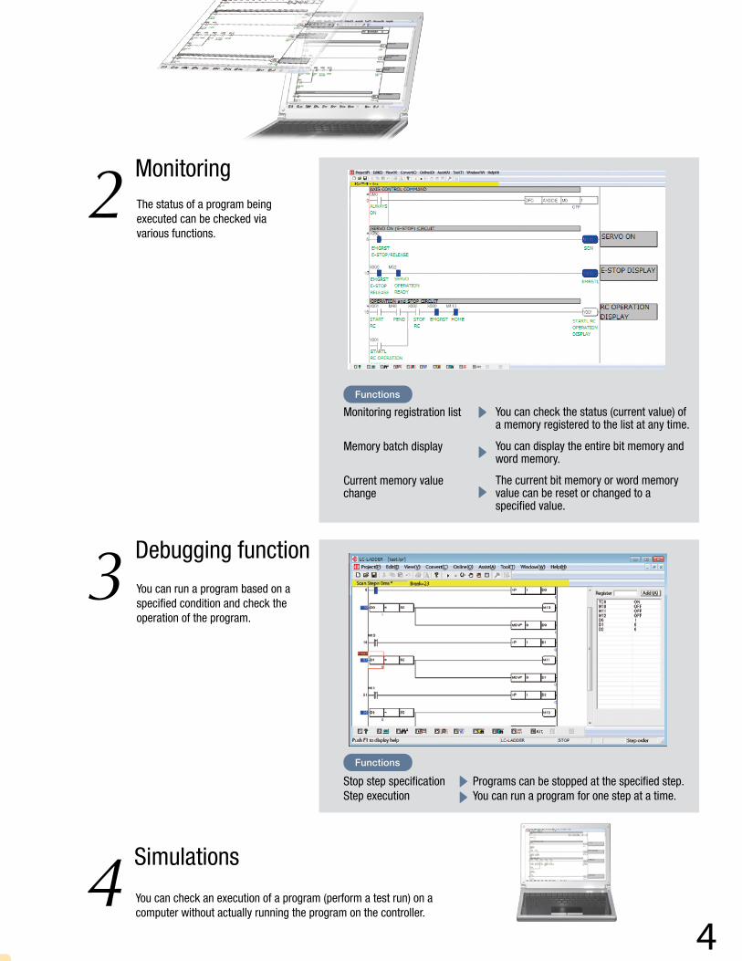
Monitoring2 The status of a program being executed can be checked via various functions.
Debugging function3 You can run a program based on a specified condition and check the operation of the program.
Simulations4 You can check an execution of a program (perform a test run) on a computer without actually running the program on the controller.
Functions
Monitoring registration list
Memory batch display
Current memory value change
You can check the status (current value) of a memory registered to the list at any time.
You can display the entire bit memory and word memory.
The current bit memory or word memory value can be reset or changed to a specified value.
Functions
Stop step specification Step execution
Programs can be stopped at the specified step.You can run a program for one step at a time.
5
Sample Program • Application Examples MSEPseries
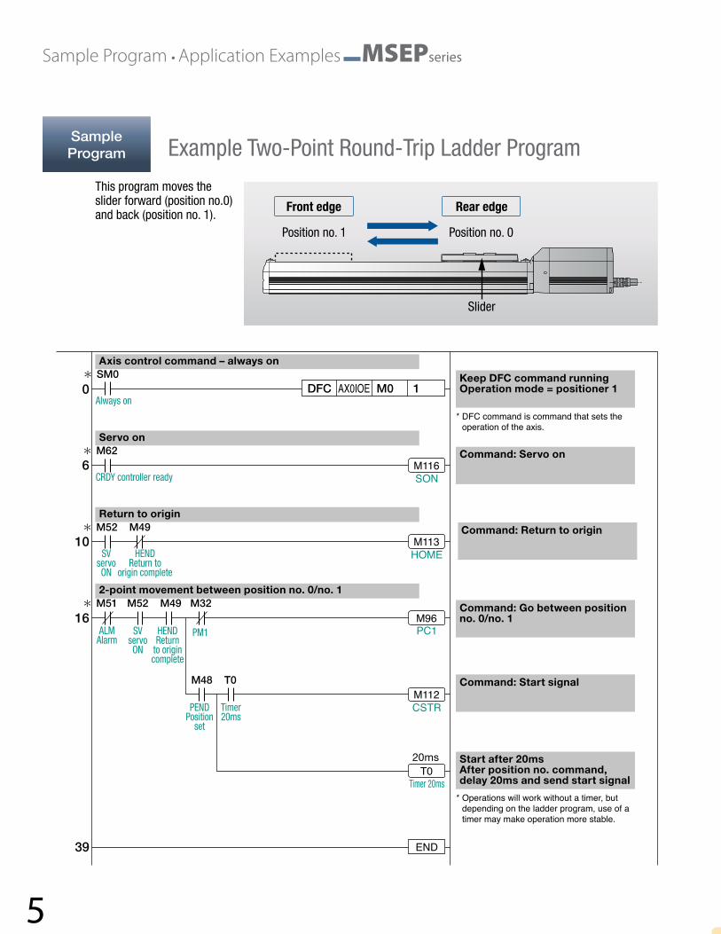
Example Two-Point Round-Trip Ladder ProgramSampleProgram
This program moves the slider forward (position no.0) and back (position no. 1).
Position no. 0
Slider
Position no. 1
Front edge Rear edge
M116
M113
M96
M112
T0
END
SON
HOME
PC1
CSTR
Timer 20ms
Timer20ms
Always on
PM1
CRDY controller ready
SV servo ON
SV servo ON
HENDReturn
to origin complete
HEND Return to
origin complete
PENDPosition
set
ALM Alarm
39
16
10
6
0 SM0
M62
M52 M49
M51 M52 M49 M32
M48 T0
DFC AX0IOE M0 1
* DFC command is command that sets the operation of the axis.
* Operations will work without a timer, but depending on the ladder program, use of a timer may make operation more stable.
20ms
Axis control command – always on
Keep DFC command runningOperation mode = positioner 1
Command: Servo on
Command: Return to origin
Command: Go between position no. 0/no. 1
Command: Start signal
Start after 20msAfter position no. command, delay 20ms and send start signal
Servo on
Return to origin
2-point movement between position no. 0/no. 1
6
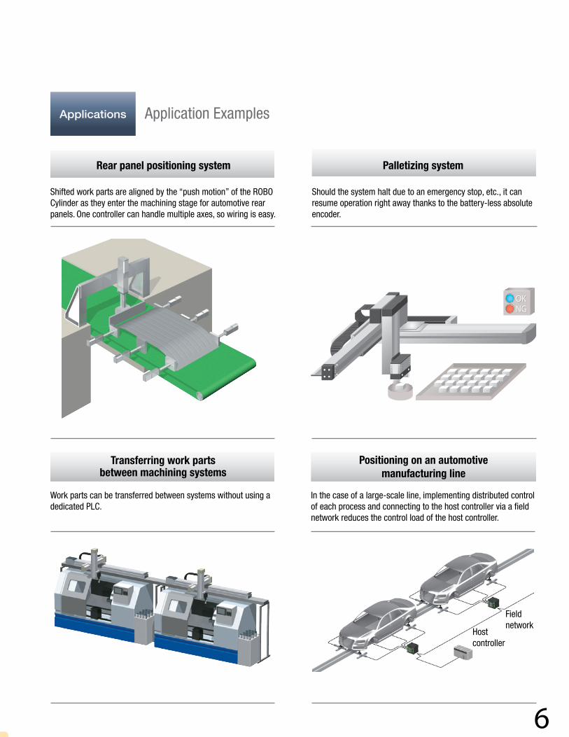
Rear panel positioning system
Shifted work parts are aligned by the “push motion” of the ROBO Cylinder as they enter the machining stage for automotive rear panels. One controller can handle multiple axes, so wiring is easy.
Transferring work parts between machining systems
Work parts can be transferred between systems without using a dedicated PLC.
Palletizing system
Should the system halt due to an emergency stop, etc., it can resume operation right away thanks to the battery-less absolute encoder.
Positioning on an automotive manufacturing line
In the case of a large-scale line, implementing distributed control of each process and connecting to the host controller via a field network reduces the control load of the host controller.
Field network
Host controller
Applications Application Examples
7
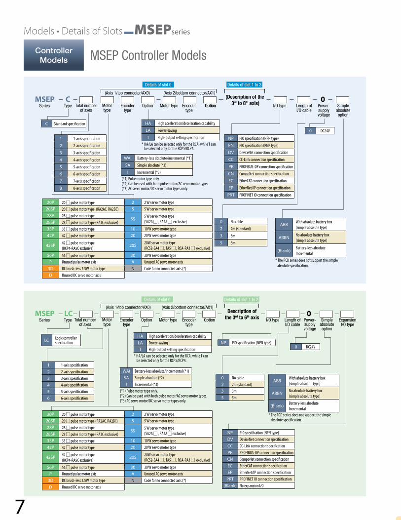
Models • Details of Slots MSEPseries
(Axis 1/top connector/AX0)
(Axis 1/top connector/AX0)
Series
Series
Type
Type
Total number of axes
Total number of axes
Motor type
Motor type
Encoder type
Encoder type
Option
Option
Motor type
Motor type
Encoder type
Encoder type
Option
Option
Option I/O type
I/O type
Length of I/O cable
Length of I/O cable
Power-supply voltage
Power-supply voltage
Simple absolute option
Simple absolute option
Expansion I/O type
(Axis 2/bottom connector/AX1)
(Axis 2/bottom connector/AX1)
MSEP
MSEP
C
LC
0
0
(Description of the 3rd to 8th axis)
Description of the 3rd to 6th axis
1 1-axis specification
2 2-axis specification
3 3-axis specification
4 4-axis specification
5 5-axis specification
6 6-axis specification
7 7-axis specification
8 8-axis specification
1 1-axis specification2 2-axis specification3 3-axis specification4 4-axis specification5 5-axis specification6 6-axis specification
NP PIO specification (NPN type)
PN PIO specification (PNP type)
DV DeviceNet connection specification
CC CC-Link connection specification
PR PROFIBUS-DP connection specification
CN CompoNet connection specification
EC EtherCAT connection specification
EP EtherNet/IP connection specification
PRT PROFINET IO connection specification
NP PIO specification (NPN type)DV DeviceNet connection specificationCC CC-Link connection specificationPR PROFIBUS-DP connection specificationCN CompoNet connection specificationEC EtherCAT connection specificationEP EtherNet/IP connection specification
PRT PROFINET IO connection specification(Blank) No expansion I/O
0 No cable
2 2m (standard)
3 3m
5 5m
0 No cable2 2m (standard)3 3m5 5m
WAI Battery-less absolute/incremental (*1)
SA Simple absolute (*2)
I Incremental (*3)
WAI Battery-less absolute/incremental (*1) SA Simple absolute (*2)
I Incremental (*3)
ABB With absolute battery box (simple absolute type)
ABBN No absolute battery box (simple absolute type)
(Blank) Battery-less absoluteIncremental
ABB With absolute battery box(simple absolute type)
ABBN No absolute battery box(simple absolute type)
(Blank) Battery-less absoluteIncremental
HA High acceleration/deceleration capability
LA Power-saving
T High-output setting specification
HA High acceleration/deceleration capabilityLA Power-savingT High-output setting specification
20P 20 pulse motor type20SP 20 pulse motor type (RA2AC, RA2BC)28P 28 pulse motor type
28SP 28 pulse motor type (RA3C exclusive)35P 35 pulse motor type42P 42 pulse motor type
42SP 42 pulse motor type(RCP4-RA5C exclusive)
56P 56 pulse motor typeP Unused pulse motor axis
3D DC brush-less 2.5W motor type D Unused DC servo motor axis
2 2 W servo motor type5 5 W servo motor type
5S 5 W servo motor type(SA2A , RA2A exclusive)
10 10 W servo motor type20 20 W servo motor type
20S 20W servo motor type(RCS2-SA4 , TA5 , RCA-RA3 exclusive)
30 30 W servo motor typeA Unused AC servo motor axisN Code for no connected axis (*)
C Standard specification
LC Logic controller specification
0 DC24V
0 DC24VNP PIO specification (NPN type)
(*1) Pulse motor type only. (*2) Can be used with both pulse motor/AC servo motor types. (*3) AC servo motor/DC servo motor types only.
20P 20 pulse motor type20SP 20 pulse motor type (RA2AC, RA2BC)28P 28 pulse motor type
28SP 28 pulse motor type (RA3C exclusive)35P 35 pulse motor type42P 42 pulse motor type
42SP 42 pulse motor type(RCP4-RA5C exclusive)
56P 56 pulse motor typeP Unused pulse motor axis
3D DC brush-less 2.5W motor type D Unused DC servo motor axis
2 2 W servo motor type5 5 W servo motor type
5S 5 W servo motor type(SA2A , RA2A exclusive)
10 10 W servo motor type20 20 W servo motor type
20S 20W servo motor type(RCS2-SA4 , TA5 , RCA-RA3 exclusive)
30 30 W servo motor typeA Unused AC servo motor axisN Code for no connected axis (*)
* The RCD series does not support the simple absolute specification.
* The RCD series does not support the simple absolute specification.
* HA/LA can be selected only for the RCA, while T can be selected only for the RCP5/RCP4.
* HA/LA can be selected only for the RCA, while T can be selected only for the RCP5/RCP4.
ControllerModels MSEP Controller Models
(*1) Pulse motor type only. (*2) Can be used with both pulse motor/AC servo motor types. (*3) AC servo motor/DC servo motor types only.
Details of slot 1 to 2
Details of slot 1 to 3
Details of slot 0
Details of slot 0
8
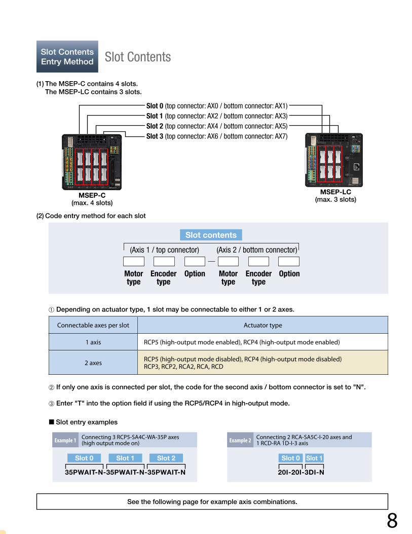
Slot Contents Entry Method Slot Contents
(1) The MSEP-C contains 4 slots. The MSEP-LC contains 3 slots.
(2) Code entry method for each slot
Slot contents
(Axis 1 / top connector) (Axis 2 / bottom connector)
Motor type
Motor type
Option OptionEncoder type
Encoder type
MSEP-C(max. 4 slots)
MSEP-LC(max. 3 slots)
Slot 0 (top connector: AX0 / bottom connector: AX1)Slot 1 (top connector: AX2 / bottom connector: AX3)Slot 2 (top connector: AX4 / bottom connector: AX5)Slot 3 (top connector: AX6 / bottom connector: AX7)
Connectable axes per slot Actuator type
1 axis RCP5 (high-output mode enabled), RCP4 (high-output mode enabled)
2 axes RCP5 (high-output mode disabled), RCP4 (high-output mode disabled)RCP3, RCP2, RCA2, RCA, RCD
➀ Depending on actuator type, 1 slot may be connectable to either 1 or 2 axes.
➁ If only one axis is connected per slot, the code for the second axis / bottom connector is set to "N".
➂ Enter "T" into the option field if using the RCP5/RCP4 in high-output mode.
Slot entry examples
See the following page for example axis combinations.
Example 1 Connecting 3 RCP5-SA4C-WA-35P axes (high output mode on)
Slot 0 Slot 1 Slot 2
35PWAIT-N-35PWAIT-N-35PWAIT-N
Connecting 2 RCA-SA5C-I-20 axes and 1 RCD-RA 1D-I-3 axisExample 2
Slot 0 Slot 1
20I-20I-3DI-N

9
Actuator Combination Examples MSEPseries
CombinationExamples Example Basic MSEP Combinations
The table below provides example combinations for MSEP-C/LC boards. Note: The MSEP-LC can only use slots 0 through 2.
View of connected axes Connected axis types Number of axes Slot 0 Slot 1 Slot 2 Slot 3 Model Standard price
Axis 1: RCP5-SA6C-WA-42P PowerCon/battery-less abso. Axis 2: RCP5-RA4C-WA-35P PowerCon/battery-less abso.
2
AX0 AX2 AX4 AX6
—
PowerCon 42Battery-less abso.
PowerCon 35Battery-less abso.
AX1 AX3 AX5 AX7
N N
Axis 1: RCP5-SA6C-WA-42P pulse/battery-less abso.Axis 2: RCP5-RA4C-WA-35P pulse/battery-less abso.Axis 3: RCA2-TCA4NA-I-20I AC servo/absolute pos.
3
AX0 AX2 AX4 AX6
—
Pulse 42Battery-less abso.
AC servo 20WAbsolute pos.
AX1 AX3 AX5 AX7Pulse 35
Battery-less abso. N
Axis 1: RCP5-SA4C-WA-35P PowerCon/battery-less abso.Axis 2: RCP5-SA4C-WA-35P PowerCon/battery-less abso.Axis 3: RCP5-RA4C-WA-35P PowerCon/battery-less abso.Axis 4: RCP5-RA4C-WA-35P PowerCon/battery-less abso.
4
AX0 AX2 AX4 AX6
—
PowerCon 35Battery-less abso.
PowerCon 35Battery-less abso.
PowerCon 35Battery-less abso.
PowerCon 35Battery-less abso.
AX1 AX3 AX5 AX7
N N N N
Axis 1: RCP5-SA4C-WA-35P PowerCon/battery-less abso.Axis 2: RCP5-SA4C-WA-35P pulse/battery-less abso.Axis 3: RCA2-TCA4NA-I-20 AC servo/absolute pos.Axis 4: RCD-RA1D-I-3D DC servo/incremental
4
AX0 AX2 AX4 AX6
—
PowerCon 42Battery-less abso.
Pulse 35Battery-less abso.
AC servo 20WAbsolute pos.
DC servoIncremental
AX1 AX3 AX5 AX7
N N N N
Axis 1: RCP5-SA6C-WA-42P PowerCon/battery-less abso.Axis 2: RCP5-RA4C-WA-35P pulse/battery-less abso.Axis 3: RCP5-RA4C-WA-35P pulse/battery-less abso.Axis 4: RCA2-TCA4NA-I-20 AC servo/absolute pos.Axis 5: RCD-RA1D-I-3D DC servo/incremental
5
AX0 AX2 AX4 AX6
—
PowerCon 42Battery-less abso.
Pulse 35Battery-less abso.
AC servo 20WAbsolute pos.
DC servoIncremental
AX1 AX3 AX5 AX7
N Pulse 35Battery-less abso. N
Axes 1-2: RCP5-RA4C-WA-35P pulse/battery-less abso.Axes 3-4: RCA2-TCA4NA-I-20 AC servo/incrementalAxes 5-6: RCD-RA1D-I-3D DC servo/incremental
6
AX0 AX2 AX4 AX6
—
Pulse 35Battery-less abso.
AC servo 20Wincremental
DC servoIncremental
AX1 AX3 AX5 AX7Pulse 35
Battery-less abso.AC servo 20Wincremental
DC servoIncremental
Axes 1-7: RCP5-RA4C-WA-35P pulse/battery-less abso. 7
AX0 AX2 AX4 AX6
—
Pulse 35Battery-less abso.
Pulse 35Battery-less abso.
Pulse 35Battery-less abso.
Pulse 35Battery-less abso.
AX1 AX3 AX5 AX7Pulse 35
Battery-less abso.Pulse 35
Battery-less abso.Pulse 35
Battery-less abso. N
Axes 1-2: RCP5-RA4C-WA-35P pulse/battery-less abso.Axes 3-4: RCA2-TCA4NA-I-20 AC servo/absolute pos.Axes 5-6: RCD-RA1D-I-3D DC servo/incremental
8
AX0 AX2 AX4 AX6
—
Pulse 35Battery-less abso.
AC servo 20WAbsolute pos.
DC servoIncremental
DC servoIncremental
AX1 AX3 AX5 AX7Pulse 35
Battery-less abso.AC servo 20WAbsolute pos.
DC servoIncremental
DC servoIncrementalRCP5-RA4C RCA2-TCA4NA RCD-RA1D
RCP5-SA6C
RCP5-SA6C
RCP5-SA6C
RCP5-RA4C
RCP5-SA4C
RCP5-RA4C
RCP5-SA4C
RCP5-RA4C
RCP5-RA4C
RCP5-RA4C
RCP5-RA4C RCA2-TCA4NA
RCA2-TCA4NA
RCA2-TCA4NA
RCA2-TCA4NA
RCD-RA1D
RCD-RA1D
RCD-RA1D

10
Note: The RCD series does not support absolute positioning.
View of connected axes Connected axis types Number of axes Slot 0 Slot 1 Slot 2 Slot 3 Model Standard price
Axis 1: RCP5-SA6C-WA-42P PowerCon/battery-less abso. Axis 2: RCP5-RA4C-WA-35P PowerCon/battery-less abso.
2
AX0 AX2 AX4 AX6
—
PowerCon 42Battery-less abso.
PowerCon 35Battery-less abso.
AX1 AX3 AX5 AX7
N N
Axis 1: RCP5-SA6C-WA-42P pulse/battery-less abso.Axis 2: RCP5-RA4C-WA-35P pulse/battery-less abso.Axis 3: RCA2-TCA4NA-I-20I AC servo/absolute pos.
3
AX0 AX2 AX4 AX6
—
Pulse 42Battery-less abso.
AC servo 20WAbsolute pos.
AX1 AX3 AX5 AX7Pulse 35
Battery-less abso. N
Axis 1: RCP5-SA4C-WA-35P PowerCon/battery-less abso.Axis 2: RCP5-SA4C-WA-35P PowerCon/battery-less abso.Axis 3: RCP5-RA4C-WA-35P PowerCon/battery-less abso.Axis 4: RCP5-RA4C-WA-35P PowerCon/battery-less abso.
4
AX0 AX2 AX4 AX6
—
PowerCon 35Battery-less abso.
PowerCon 35Battery-less abso.
PowerCon 35Battery-less abso.
PowerCon 35Battery-less abso.
AX1 AX3 AX5 AX7
N N N N
Axis 1: RCP5-SA4C-WA-35P PowerCon/battery-less abso.Axis 2: RCP5-SA4C-WA-35P pulse/battery-less abso.Axis 3: RCA2-TCA4NA-I-20 AC servo/absolute pos.Axis 4: RCD-RA1D-I-3D DC servo/incremental
4
AX0 AX2 AX4 AX6
—
PowerCon 42Battery-less abso.
Pulse 35Battery-less abso.
AC servo 20WAbsolute pos.
DC servoIncremental
AX1 AX3 AX5 AX7
N N N N
Axis 1: RCP5-SA6C-WA-42P PowerCon/battery-less abso.Axis 2: RCP5-RA4C-WA-35P pulse/battery-less abso.Axis 3: RCP5-RA4C-WA-35P pulse/battery-less abso.Axis 4: RCA2-TCA4NA-I-20 AC servo/absolute pos.Axis 5: RCD-RA1D-I-3D DC servo/incremental
5
AX0 AX2 AX4 AX6
—
PowerCon 42Battery-less abso.
Pulse 35Battery-less abso.
AC servo 20WAbsolute pos.
DC servoIncremental
AX1 AX3 AX5 AX7
N Pulse 35Battery-less abso. N
Axes 1-2: RCP5-RA4C-WA-35P pulse/battery-less abso.Axes 3-4: RCA2-TCA4NA-I-20 AC servo/incrementalAxes 5-6: RCD-RA1D-I-3D DC servo/incremental
6
AX0 AX2 AX4 AX6
—
Pulse 35Battery-less abso.
AC servo 20Wincremental
DC servoIncremental
AX1 AX3 AX5 AX7Pulse 35
Battery-less abso.AC servo 20Wincremental
DC servoIncremental
Axes 1-7: RCP5-RA4C-WA-35P pulse/battery-less abso. 7
AX0 AX2 AX4 AX6
—
Pulse 35Battery-less abso.
Pulse 35Battery-less abso.
Pulse 35Battery-less abso.
Pulse 35Battery-less abso.
AX1 AX3 AX5 AX7Pulse 35
Battery-less abso.Pulse 35
Battery-less abso.Pulse 35
Battery-less abso. N
Axes 1-2: RCP5-RA4C-WA-35P pulse/battery-less abso.Axes 3-4: RCA2-TCA4NA-I-20 AC servo/absolute pos.Axes 5-6: RCD-RA1D-I-3D DC servo/incremental
8
AX0 AX2 AX4 AX6
—
Pulse 35Battery-less abso.
AC servo 20WAbsolute pos.
DC servoIncremental
DC servoIncremental
AX1 AX3 AX5 AX7Pulse 35
Battery-less abso.AC servo 20WAbsolute pos.
DC servoIncremental
DC servoIncremental
MSEP-C-4-35PWAIT-N-35PWAIT-N-
35PWAIT-N-35PWAIT-N-NP-2-0
Slot 0
Slot 2 Slot 3
Slot 1
MSEP-LC-3-42PWAI-35PWAI-20SA-N-NP-2-0-ABBSlot 0 Slot 1
MSEP-LC-2-42PWAIT-N-35PWAIT-N-NP-2-0
Bottom connector
Bottom connectorTop connector
Axis no.Slot 0 Slot 1
Top connector
MSEP-C-4-42PWAIT-N-35PWAI-N-
20SA-N-3DI-N-NP-2-0-ABB
Slot 0 Slot 1
Slot 2 Slot 3
MSEP-C-8-35PWAI-35PWAI-20SA-20SA-
3DI-3DI-3DI-3DI-NP-2-0-ABB
Slot 0 Slot 1
Slot 2 Slot 3
MSEP-C-7-35PWAI-35PWAI-35PWAI-35PWAI-
35PWAI-35PWAI-35PWAI-N-NP-2-0
Slot 0
Slot 2 Slot 3
Slot 1
MSEP-C-5-42PWAIT-N-Slot 0
35PWAI-35PWAI-20SA-N-3DI-N-NP-2-0-ABBSlot 1 Slot 2 Slot 3
MSEP-C-6-35PWAI-35PWAI-
20I-20I-3DI-3DI—NP-2-0
Slot 0
Slot 1 Slot 2

11
Standard Price Chart MSEPseries
2
Prices by slot type(Add all prices for slots used)
Slots Model Price
Pulsemotor
1 axis
Absolute positioning(for PowerCon) PSAT-N —
Battery-less abso. / Incremental
(for PowerCon)PWAIT-N —
Absolute positioning(for standard) PSA-N —
Battery-less abso. / Incremental
(for standard)PWAI-N —
2 axes
Absolute Absolutepositioning + positioning (for standard) (for standard)
PSA-PSA —
Battery-less abso. / Battery-less abso./ Incremental + Incremental(for standard) (for standard)
PWAI-PWAI —
AC servo motor
1 axis
Incremental(for standard) I-N —
Absolute positioning(for standard) SA-N —
2 axes
Incremental + Incremental(for standard) (for standard)
I-I —
Absolute Absolutepositioning + positioning (for standard) (for standard)
SA-SA —
DC servo motor
1 axis
Incremental(for standard) 3DI-N —
2 axes
Incremental + Incremental(for standard) (for standard)
3DI-3DI —
StandardPrice Chart Standard Price Chart
The standard MSEP controller price is built from the base model price (table 1 below) with prices added depending on slot types (table 2 ), absolute positioning quantity (table 3 ), absolute backup box quantity (table 4 ), I/O type (table 5 ), and expanded I/O type (table 6 ).
1 Base price by model
Select between the standard controller (MSEP-C) or controller with PLC (MSEP-LC).
2 Prices by slot type
Add the price for the desired slot types designated in slots 0 through 3.
3 Prices by absolute position quantity
Add the price for the desired number of axes you wish to operate via absolute positioning.
1
Base price by model
Type Model Price
Standard MSEP-C —
With PLC MSEP-LC —
3
Absolute position quantity
Axes Price
1 —
2 —
3 —
4 —
5 —
6 —
7 —
8 —
*Add the motor number to the empty squares () above.

12
4 Absolute backup box quantity
Add the price for the desired number of axes to install a data backup battery (model ABB) on for absolute data.
5 I/O type
Select the controller I/O type. (Only NP can be selected for controllers with PLC.)
6 Expanded I/O type
Select the controller's expanded I/O type. (Not used for standard-model controllers.)
*Do not add prices from tables 3 and 4 for battery-less absolute types.
4
Absolute backup box quantity
Axes Price
1 —
2 —
3 —
4 —
5 —
6 —
7 —
8 —
Total
Specification specific standard price
5I/O type
(Only NP can be selected for controllers with PLC)
Type Model Price
PIO (NPN) specification NP —
PIO (PNP) specification PN —
DeviceNet specification DV —
CC-Link specification CC —
PROFIBUS-DP specification PR —
CompoNet specification CN —
EtherCAT specification EC —
EtherNet/IP specification EP —
PROFINET IO specification PRT —
6
Expanded I/O type(Not used for standard-model controllers)
Type Model Price
PIO (NPN) specification NP —
DeviceNet specification DV —
CC-Link specification CC —
PROFIBUS-DP specification PR —
CompoNet specification CN —
EtherCAT specification EC —
EtherNet/IP specification EP —
PROFINET IO specification PRT —

13
System Configuration MSEPseries
SystemConfiguration System Configuration Map
RCP5 series RCP4 series RCP3 series
MSEP-C
OptionPC compatible software(See P. 24)RS232 connection versionModel RCM-101-MWUSB connection versionModel RCM-101-USB
OptionTeaching Pendant(See P. 24)Model TB-01-C
OptionAbsolute battery box (See P. 24)Model MSEP-ABB
Replacement battery(See P. 24)Model AB-7
PLC
Field NetworkDeviceNet, CC-Link, PROFIBUS-DP,CompoNet, EtherCAT, EtherNet/IP, PROFINET IO
Supplied with the PIO specification controller
PIO flat cable(See P. 26)Model CB-MSEP-PI0020Standard length: 2m
* There are choices of either the PIO specification or the field network specification.
* PowerCon (high-output drivers) and mini cylinders are supported by Ver.9.06.00.00 or later.
* If the absolute position encoder specification is selected as a controller unit, the absolute data backup battery is included. (See P. 23 for dimensions)
* The gateway parameter configuration tool included with the PC compatible software is required for field network setup. Please purchase the PC compatible software if you do not have this tool. (See P. 24)
* Field network connection cable is not included.
The cable is supplied with the PC compatible software
The cable is supplied with the absolute battery box
OptionDC24V power supplyModel PS-241 (100 V input)Model PS-242 (200 V input)
Integrated motor-encoder cable(See P. 25)Model CB-CAN-MPA
Integrated motor-encoder robot cable(See P. 25)Model CB-CAN-MPA-RB
Integrated motor-encoder cable(See P. 25)Model CB-CA-MPA
Integrated motor-encoder robot cable(See P. 25)Model CB-CA-MPA-RB
Integrated motor-encoder robot cable(See P. 25)Model CB-APSEP-MPA* Only robot cable is available
for this model.
5m
0.5m
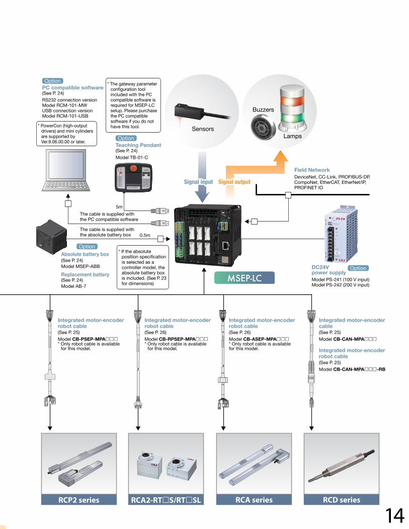
14RCP2 series RCA2-RTS/RTSL RCA series RCD series
MSEP-LC
OptionPC compatible software(See P. 24)RS232 connection versionModel RCM-101-MWUSB connection versionModel RCM-101-USB
OptionTeaching Pendant(See P. 24)Model TB-01-C
OptionAbsolute battery box (See P. 24)Model MSEP-ABB
Replacement battery(See P. 24)Model AB-7
Field NetworkDeviceNet, CC-Link, PROFIBUS-DP,CompoNet, EtherCAT, EtherNet/IP, PROFINET IO
* PowerCon (high-output drivers) and mini cylinders are supported by Ver.9.06.00.00 or later.
* The gateway parameter configuration tool included with the PC compatible software is required for MSEP-LC setup. Please purchase the PC compatible software if you do not have this tool.
* If the absolute position specification is selected as a controller model, the absolute battery box is included. (See P. 23 for dimensions)
The cable is supplied with the PC compatible software
The cable is supplied with the absolute battery box
OptionDC24V power supplyModel PS-241 (100 V input)Model PS-242 (200 V input)
Integrated motor-encoder robot cable(See P. 25)Model CB-PSEP-MPA* Only robot cable is available
for this model.
Integrated motor-encoder robot cable(See P. 26)Model CB-RPSEP-MPA* Only robot cable is available
for this model.
Integrated motor-encoder robot cable(See P. 26)Model CB-ASEP-MPA* Only robot cable is availablefor this model.
Integrated motor-encoder cable(See P. 25)Model CB-CAN-MPA
Integrated motor-encoder robot cable(See P. 25)Model CB-CAN-MPA-RB
Signal input Signal output
Sensors
Buzzers
Lamps
5m
0.5m

15
Control Methods MSEPseries
Type External viewControle methods
No. of control axes
PIO controlled motion mode
Field network control motion mode
Using high-output driver
Using standard driver
MSEP-C Positioner function 4 8
MSEP-LCPLC function
+Positioner function
3 6 — (*)
This mode allows external devices to move actuators based on an ON/OFF signal assigned to the PIO. Six different types of PIO-assigned signal patterns can be selected and used (see table below).* Not available with the MSEP-LC.
The MSEP-C controller itself has no sequencing functionality, so the positioner accepts movement positioning and other commands from a higher-level PLC to conduct operations.The MSEP-LC executes a ladder program inside the controller, allowing it to communicate with external devices via I/O to operate axes (positional operation).
Motion Mode No. 0 1 2 3 4 5
Motion Mode Type Standard 2-position motion
Speed change during movement Position data change 2-input/ 3-position
motion3-input/ 3-position
motionContinuous cycle
operation
Feature
2-position motion 2-position motion 2-position motion 3-position motion 3-position motion 2-position continuous motion
Push Push Push Push Push Push
– Speed change during movement
Travel position data change – – –
Solenoid configurations Single Double Single Double Single Double – – –
Input
0 Motion signal
Motion signal 1
Motion signal
Motion signal 1
Motion signal
Motion signal 1 Motion signal 1 Retract motion
signal Continuous motion signal
1 Pause signal
Motion signal 2
Pause signal
Motion signal 2
Pause signal
Motion signal 2 Motion signal 2 Extend
motion signal Pause signal
2 Reset signal Speed change signal (Reset signal)
Target position change signal (Reset signal) Reset signal Intermediate point motion
command signal (Reset signal) Reset signal
3 –/Servo-ON signal
–/Servo-ON signal
–/Servo-ON signal
–/Servo-ON signal
–/Servo-ON signal
–/Servo-ON signal
Output
0 Retract motion output signal
Retract motion output signal
Retract motion output signal
Retract motion output signal
Retract motion output signal
Retract motionoutput signal
1 Extend motion output signal
Extend motion output signal
Extend motion output signal
Extend motion output signal
Extend motion output signal
Extend motion output signal
2 Homing complete signal/ Servo-ON output signal
Homing complete signal/ Servo-ON output signal
Homing complete signal/ Servo-ON output signal
Intermediate point position output signal
Intermediate point position output signal
Homing complete signal/ Servo-ON output signal
3 Alarm output signal/Servo-ON output signal
Alarm output signal/Servo-ON output signal
Alarm output signal/Servo-ON output signal
Alarm output signal/Servo-ON output signal
Alarm output signal/Servo-ON output signal
Alarm output signal/Servo-ON output signal
* Please refer to the controller operation instruction for the above signal information. (Download is available from our website)
ControlMethods
PIOControl Method by Controller Type
Control Methods
PIO Controlled Motion Mode
1
1
2
2 3
* If using the MSEP-LC in a field network, ladder program-based data transfer and axis operation is required.

16
There are five operation modes to choose from when using the MSEP-C over a field network.Data required for operation (target position, velocity, acceleration, push current, etc.) is written by a PLC or such connected to a higher-level device into a defined address. If operating the MSEP-LC via a field network, data required for axis operation is transferred via ladder program, and axis operation is conducted based on this ladder program motion command.* Ladder programming is required for MSEP-LC axis operations.
Motion pattern (*1) Description Outline
Positioner 1/Simple numerical
mode
Positioner 1 mode is programmable up to 256 positions of data to designate the stop position. The simple numerical control allows designating the target position numerically. They both have the capability of monitoring the current position.
Direct numericalcontrol mode
This mode allows designating the target position, velocity, acceleration, and current parameters for pushing. Also, it is capable of monitoring the current position, real-time velocity, and the electric current command value.
Positioner 2 mode
Positioner 2 mode is programmable up to 256 positions of data to designate stop positions, and this mode does not allow monitoring of the current position. This mode has less in/out data transfer volume than the positioner 1 mode.
Positioner 3 mode
Positioner 3 mode is programmable up to 256 positions of data to designate stop positions, and this mode does not allow monitoring of the current position. This mode has less in/out data transfer volume from the positioner 2 mode, and operates under minimum number of signals..
SEP I/OThis mode allows the same functions with the field network as the PIO controlled motion mode 0 to 5 as described in the previous page.
Please refer to the PIO controlled motion mode.
(*1) For MSEP-C, only the positioner 3 mode and the SEP I/O mode are available with CompoNet.
Communication via field network
Actuator
Communication via field network
Actuator
Communication via field network
Actuator
Communication via field network
Actuator
PLC
Target positionTarget position numberControl signal
Current positionEnd position numberStatus signal
PLC
Target position numberControl signal
End position numberStatus signal
PLC
Target position numberControl signal
End position numberStatus signal
PLC
Target position, Positioning width, Velocity, Acceleration/DecelerationPushing percentage, Control signal
Current positionCurrent value (Designated value)Current velocity (Designated value)Alarm code, Status signal
Field Network Control Motion Mode3

17
Operation Methods MSEPseries
PIO Specification
Field Network Specification
Input position data to the MSEP-C and specify a desired position number via PIO from the host PLC to operate the actuator. PLC
PLC
Positioning complete signal Completed position number
Positioning complete signal Completed position number
Current position
Specification of target position (Specification of position data)
Specification of target position (Position specification)
(Direct numerical specification)
Ladder logic program
Ladder logic program
Actuator
Actuator
Position data
Position data
Teaching pendant ( Refer to P. 24)
PC compatible software ( Refer to P. 24)
Teaching pendant ( Refer to P. 24)
PC compatible software ( Refer to P. 24)
Gateway parameter setting tool
Tools required for setting
Tools required for setting
1
1
1
1
2
2
3
2
2
* You only need either or to complete all necessary settings.
* You only need either or to complete all the necessary settings. comes with the PC compatible software.
As with the PIO specification, input position data to the MSEP and specify a desired position number via a field network from the PLC to operate the actuator.
The PLC sends numerical position, speed and other data via a field network to operate the actuator.
1
2
3
OperationMethods How to Operate MSEP-C

18
PIO Specification
The MSEP-LC runs a ladder logic program internally to operate the axes and control the PIO I/O signals. The axes can be operated either by using position data or specifying coordinates directly.
Field Network Specification
The MSEP-LC runs a ladder logic program internally to operate the axes and control I/O signals via a network. The axes can be operated either by using position data or specifying coordinates directly.
General-purpose output signals
General-purpose input signals
Ladder logic program
Ladder logic program
Actuator
Actuator
Position data
Position data
Teaching pendant ( Refer to P. 24)
PC compatible software ( Refer to P. 24)
Gateway parameter setting tool
Ladder logic support software ( Refer to P. 3)
Teaching pendant ( Refer to P. 24)
PC compatible software ( Refer to P. 24)
Gateway parameter setting tool
Ladder logic support software ( Refer to P. 3)
Tools required for setting
Tools required for setting
1
1
2
2
Peripheral equipment
3
3
4
4
General-purpose output signalsPosition data
General-purpose input signalsPosition data
Peripheral equipment
* You only need either or to complete all the necessary settings. comes with the PC compatible software. is downloadable from our website.
1 2
3
4
* You only need either or to complete all the necessary settings. comes with the PC compatible software. is downloadable from our website.
1 2
3
4
How to Operate MSEP-LC
19
LadderProgram
Ladder Program MSEPseries
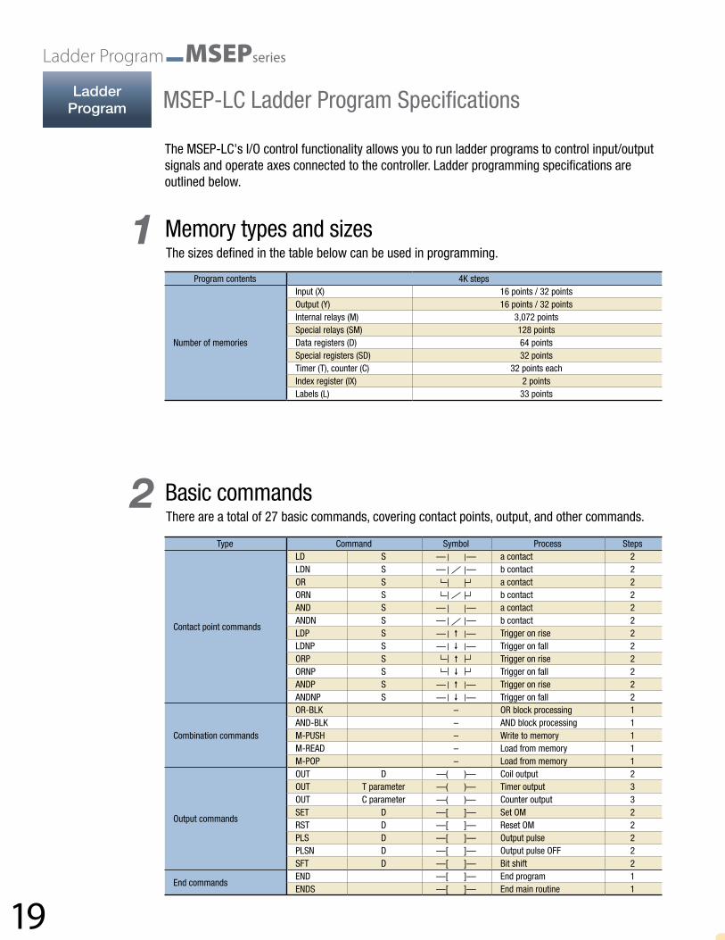
Type Command Symbol Process Steps
Contact point commands
LD S — — a contact 2LDN S — — b contact 2OR S a contact 2ORN S b contact 2AND S — — a contact 2ANDN S — — b contact 2LDP S — — Trigger on rise 2LDNP S — — Trigger on fall 2ORP S Trigger on rise 2ORNP S Trigger on fall 2ANDP S — — Trigger on rise 2ANDNP S — — Trigger on fall 2
Combination commands
OR-BLK – OR block processing 1AND-BLK – AND block processing 1M-PUSH – Write to memory 1M-READ – Load from memory 1M-POP – Load from memory 1
Output commands
OUT D —( )— Coil output 2OUT T parameter —( )— Timer output 3OUT C parameter —( )— Counter output 3SET D —[ ]— Set OM 2RST D —[ ]— Reset OM 2PLS D —[ ]— Output pulse 2PLSN D —[ ]— Output pulse OFF 2SFT D —[ ]— Bit shift 2
End commandsEND —[ ]— End program 1ENDS —[ ]— End main routine 1
Program contents 4K steps
Number of memories
Input (X) 16 points / 32 pointsOutput (Y) 16 points / 32 pointsInternal relays (M) 3,072 pointsSpecial relays (SM) 128 pointsData registers (D) 64 pointsSpecial registers (SD) 32 pointsTimer (T), counter (C) 32 points eachIndex register (IX) 2 pointsLabels (L) 33 points
Memory types and sizes
Basic commands
MSEP-LC Ladder Program Specifications
1
2
The sizes defined in the table below can be used in programming.
There are a total of 27 basic commands, covering contact points, output, and other commands.
The MSEP-LC's I/O control functionality allows you to run ladder programs to control input/output signals and operate axes connected to the controller. Ladder programming specifications are outlined below.
20
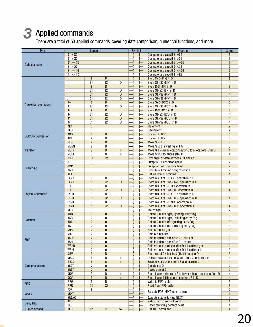
Type Command Symbol Process Steps
Data compare
S1 = S2 —[ ]— Compare and pass if S1=S2 3S1 > S2 —[ ]— Compare and pass if S1>S2 3S1 >= S2 —[ ]— Compare and pass if S1>=S2 3S1 < S2 —[ ]— Compare and pass if S1<S2 3S1 <= S2 —[ ]— Compare and pass if S1<=S2 3S1 <> S2 —[ ]— Compare and pass if S1≠S2 3
Numerical operations
+ S D —[ ]— Store S+D (BIN) in D 3+ S1 S2 D —[ ]— Store S1+S2 (BIN) in D 4- S D —[ ]— Store D-S (BIN) in D 3- S1 S2 D —[ ]— Store S1-S2 (BIN) in D 4* S1 S2 D —[ ]— Store S1×S2 (BIN) in D 4/ S1 S2 D —[ ]— Store S1÷S2 (BIN) in D 4B+ S D —[ ]— Store S+D (BCD) in D 3B+ S1 S2 D —[ ]— Store S1+S2 (BCD) in D 4B- S D —[ ]— Store D-S (BCD) in D 3B- S1 S2 D —[ ]— Store S1-S2 (BCD) in D 4B* S1 S2 D —[ ]— Store S1×S2 (BCD) in D 4B/ S1 S2 D —[ ]— Store S1÷S2 (BCD) in D 4INC D —[ ]— Increment 2DEC D —[ ]— Decrement 2
BCD/BIN conversionBCD S D —[ ]— Convert to BCD 3BIN S D —[ ]— Convert to BIN 3
Transfer
MOV S D —[ ]— Move S to D 3MOVN S D —[ ]— Move S to D, inverting all bits 3MCPY S D n —[ ]— Move the value n locations after S to n locations after D 4MSET S D n —[ ]— Move S to n locations after D 4XCHG D1 D2 —[ ]— Exchange bit data between D1 and D2 3
Branching
JE S —[ ]— Jump to L if conditions pass 2JMP L —[ ]— Jump to L with no conditions 2CALL L —[ ]— Execute subroutine designated in L 2RET —[ ]— Return from subroutine 1
Logical operations
LAND S D —[ ]— Store result of S/D AND operation in D 3LAND S1 S2 D —[ ]— Store result of S1/S2 AND operation in D 4LOR S D —[ ]— Store result of S/D OR operation in D 3LOR S1 S2 D —[ ]— Store result of S1/S2 OR operation in D 4LXOR S D —[ ]— Store result of S/D XOR operation in D 3LXOR S1 S2 D —[ ]— Store result of S1/S2 XOR operation in D 4LXNR S D —[ ]— Store result of S/D NOR operation in D 3LXNR S1 S2 D —[ ]— Store result of S1/S2 NOR operation in D 4NEG D —[ ]— Invert sign 2
Rotation
ROR D n —[ ]— Rotate D n bits right, ignoring carry flag 3RCR D n —[ ]— Rotate D n bits right, including carry flag 3ROL D n —[ ]— Rotate D n bits left, ignoring carry flag 3RCL D n —[ ]— Rotate D n bits left, including carry flag 3
Shift
SHR D n —[ ]— Shift D n bits right 3SHL D n —[ ]— Shift D n bits left 3BSHR D n —[ ]— Shift location n bits after D 1 bit right 3BSHL D n —[ ]— Shift location n bits after D 1 bit left 3WSHR D n —[ ]— Shift value n locations after D 1 location right 3WSHL D n —[ ]— Shift value n locations after D 1 location left 3
Data processing
SUM S D —[ ]— Store no. of ON bits in S (16-bit data) in D 3DECO S D n —[ ]— Decode lowest n bits of S and store 2n bits from D 4ENCO S D n —[ ]— Encode value 2n bits from S and store in D 4BSET D n —[ ]— Set bit n of D 3BRST D n —[ ]— Reset bit n of D 3DDV S D n —[ ]— Store lower n places of S to lower 4 bits n locations from D 4DCV S D n —[ ]— Store lower 4 bits n locations from S in D 4
FIFOFIFW S D —[ ]— Write to FIFO table 3FIFR D1 D2 —[ ]— Read from FIFO table 3
LoopsFOR S —[ ]—
Execute FOR-NEXT loop n times2
NEXT —[ ]— 1BREAK —[ ]— Execute step following NEXT 1
Carry flagSTC —[ ]— Set carry flag contact point 1CLC —[ ]— Reset carry flag contact point 1
DFC command DFC fcn S1 S2 —[ ]— Call DFC command 4
Applied commands3There are a total of 53 applied commands, covering data comparison, numerical functions, and more.
21
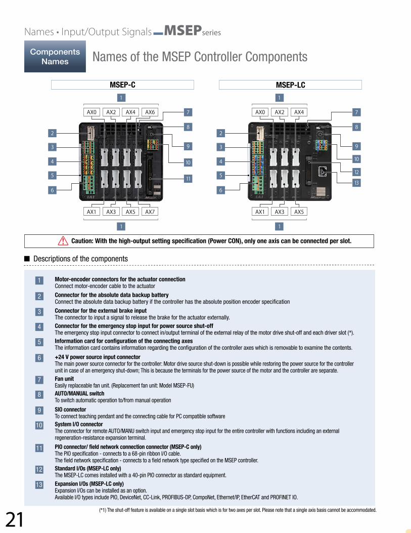
Names • Input/Output Signals MSEPseries
MSEP-C MSEP-LC
Caution: With the high-output setting specification (Power CON), only one axis can be connected per slot.
Descriptions of the components
Motor-encoder connectors for the actuator connection Connect motor-encoder cable to the actuator
Connector for the absolute data backup battery Connect the absolute data backup battery if the controller has the absolute position encoder specification
Connector for the external brake input The connector to input a signal to release the brake for the actuator externally.Connector for the emergency stop input for power source shut-off The emergency stop input connector to connect in/output terminal of the external relay of the motor drive shut-off and each driver slot (*).Information card for configuration of the connecting axes The information card contains information regarding the configuration of the controller axes which is removable to examine the contents.
+24 V power source input connector The main power source connector for the controller: Motor drive source shut-down is possible while restoring the power source for the controller unit in case of an emergency shut-down; This is because the terminals for the power source of the motor and the controller are separate.Fan unit Easily replaceable fan unit. (Replacement fan unit: Model MSEP-FU)AUTO/MANUAL switch To switch automatic operation to/from manual operation
SIO connector To connect teaching pendant and the connecting cable for PC compatible softwareSystem I/O connector The connector for remote AUTO/MANU switch input and emergency stop input for the entire controller with functions including an external regeneration-resistance expansion terminal.
PIO connector/ field network connection connector (MSEP-C only) The PIO specification - connects to a 68-pin ribbon I/O cable. The field network specification - connects to a field network type specified on the MSEP controller.Standard I/Os (MSEP-LC only) The MSEP-LC comes installed with a 40-pin PIO connector as standard equipment. Expansion I/Os (MSEP-LC only) Expansion I/Os can be installed as an option. Available I/O types include PIO, DeviceNet, CC-Link, PROFIBUS-DP, CompoNet, Ethernet/IP, EtherCAT and PROFINET IO.
(*1) The shut-off feature is available on a single slot basis which is for two axes per slot. Please note that a single axis basis cannot be accommodated.
1
2
3
4
5
6
7
8
9
10
11
12
13
ComponentsNames Names of the MSEP Controller Components

22
MSEP-LC (Expansion I/O specification)MSEP-C (PIO specification)
The MSEP-C has dedicated inputs and outputs set to PIO signals at 34 input points/34 output points. The axis operates when each signal is turned ON/OFF from the host PLC. With the MSEP-LC, general-purpose input/output signals at 32 input points/32 output points can be used in a ladder program by using the standard 16 input points/16 output points plus expansion I/Os.
Standard I/Os
Expansion I/Os
PIO connector
PIO connector
PIO Wiring Diagram for MSEP-C
PIO Wiring Diagram for MSEP-LC
Connector name: HIF6-68PA-1.27DS (Hirose Electric)Pin No. Category Signal ID Pin No. Category Signal ID
A1 24V For I/O A18Output
(Axis No. 0)
OUT0A2
Input(Axis No. 0)
IN0 A19 OUT1A3 IN1 A20 OUT2A4 IN2 A21 OUT3A5 IN3 A22
Output (Axis No. 1)
OUT4A6
Input(Axis No. 1)
IN4 A23 OUT5A7 IN5 A24 OUT6A8 IN6 A25 OUT7A9 IN7 A26
Output (Axis No. 2)
OUT8A10
Input(Axis No. 2)
IN8 A27 OUT9A11 IN9 A28 OUT10A12 IN10 A29 OUT11A13 IN11 A30
Output (Axis No. 3)
OUT12A14
Input(Axis No. 3)
IN12 A31 OUT13A15 IN13 A32 OUT14A16 IN14 A33 OUT15A17 IN15 A34 0V For I/O
Pin No. Category Assigned memory Pin No. Category Assigned memoryA1
—
24V external input
A11
Input
X006A2 A12 X007A3 Not used A13 X008A4 Not used A14 X009A5
Input
X000 A15 X00AA6 X001 A16 X00BA7 X002 A17 X00CA8 X003 A18 X00DA9 X004 A19 X00E
A10 X005 A20 X00F
Pin No. Category Assigned memory Pin No. Category Assigned memoryA1
—
24V external input
A11
Input
X016A2 A12 X017A3 Not used A13 X018A4 Not used A14 X019A5
Input
X010 A15 X01AA6 X011 A16 X01BA7 X012 A17 X01CA8 X013 A18 X01DA9 X014 A19 X01E
A10 X015 A20 X01F
Pin No. Category Assigned memory Pin No. Category Assigned memoryB1
Output
Y000 B11
Output
Y00AB2 Y001 B12 Y00BB3 Y002 B13 Y00CB4 Y003 B14 Y00DB5 Y004 B15 Y00EB6 Y005 B16 Y00FB7 Y006 B17
—
Not usedB8 Y007 B18 Not usedB9 Y008 B19
0V external inputB10 Y009 B20
Pin No. Category Assigned memory Pin No. Category Assigned memoryB1
Output
Y010 B11
Output
Y01AB2 Y011 B12 Y01BB3 Y012 B13 Y01CB4 Y013 B14 Y01DB5 Y014 B15 Y01EB6 Y015 B16 Y01FB7 Y016 B17
—
Not usedB8 Y017 B18 Not usedB9 Y018 B19
0V external inputB10 Y019 B20
Connector name: HIF6-68PA-1.27DS (Hirose Electric)Pin No. Category Signal ID Pin No. Category Signal ID
B1 24V For I/O B18Output
(Axis No. 4)
OUT16B2
Input(Axis No. 4)
IN16 B19 OUT17B3 IN17 B20 OUT18B4 IN18 B21 OUT19B5 IN19 B22
Output (Axis No. 5)
OUT20B6
Input(Axis No. 5)
IN20 B23 OUT21B7 IN21 B24 OUT22B8 IN22 B25 OUT23B9 IN23 B26
Output (Axis No. 6)
OUT24B10
Input(Axis No. 6)
IN24 B27 OUT25B11 IN25 B28 OUT26B12 IN26 B29 OUT27B13 IN27 B30
Output (Axis No. 7)
OUT28B14
Input(Axis No. 7)
IN28 B31 OUT29B15 IN29 B32 OUT30B16 IN30 B33 OUT31B17 IN31 B34 0V For I/O
Input/Output Signals
PIOInput/Output (PIO) Signals

23
Specifications • Dimensions • Options MSEPseries
Specification item DescriptionNumber of axes in the controller 8 axes MAX (MSEP-C), 6 axes MAX (MSEP-LC)Controller/ Motor input power DC24V ±10%Brake power 0.15 A x Number of axesCurrent consumption by control power 0.8AController inrush current 5A MAX, under 30 ms
Motor consumption current
Servo motor type Rated ampereMaximum
Pulse motor type
Rated ampere MaximumEnergy saverStandard/
Hi-accel./decel.2W 0.8A 4.6A 20P 1.0A 2.0A
3W(RCD) 0.7A 1.5A 28P 1.0A 2.0A5W 1.0A 6.4A
35P 2.2 A (high output
disabled) 3.5 A
(high output spec.)
2.2 A (high output
disabled) 4.2 A
(high output spec.)
10W(RCL)1.3A
6.4A10W(RCA/RCA2) 2.5A 4.4A
42P20W 1.3A 2.5A 4.4A20 W (20S type) 1.7A 3.4A 5.1A
56P30W 1.3A 2.2A 4.4AMotor inrush current Slot numbers x 10A MAX, under 5msMotor-encoder cable length Maximum length 20m (*10m for absolute positioning)Serial communication (SIO port: dedicated teaching) RS485 1ch (Modbus protocol compatible) Speed 9.6 to 230.4kbps
External interfacePIO specification
PIO specification : DC24V dedicated signal in/output; Maximum input of 4 points/axis; Maximum output of 4 points/axis;Maximum cable length 10 m
Field network specification DeviceNet, CC-Link, PROFIBUS-DP, CompoNet, EtherNet/IP, EtherCAT, PROFINET IOData configuration and input method PC compatible software application, touch panel teaching pendant, gateway parameter configuration toolData retention memory Restore the position data and parameter in non-volatile memory (unlimited input)
Positioning pointsPIO specification: 2 or 3 pointsField network specification: 256 points (no limited input for the simple numerical control and the direct numerical control)(Note) The number of designated positions vary depending on the parameter configuration with motion mode selection.
LED display (On the front panel)LED for driver status, 8 LEDs (for each driver board)Status LED, 4 LEDs (PIO specification), 7 LEDs (Fieldbus specification)
Electromagnetic brake force release Enable to force-release by transmitting a deactivation signal to each axis (DC24V input).Surge protection Overcurrent protection (A cut-off semiconductor circuit is built-in on each slot)Electric shock protection Class I basic insulationInsulation resistance DC500V 10MΩ
Weight620g with the absolute position encoder specification plus 1950g absolute data backup battery(8-axis specification)
Cooling method Forced-air coolingAmbient operating temperature/humidity 0 to 40°C, under 85% RH (non-condensing)International Protection code IP20PLC function (MSEP-LC) Dedicated ladder program (4,000 steps total)
Controller (The same dimensions apply to the MSEP-C/LC)
Absolute data backup battery box
35.4
(35m
m D
IN
rail
wid
th)
35.4
(35m
m D
IN
rail
wid
th)
59 fr
om th
e ce
nter
of D
IN ra
il59
from
the
cent
er o
f DIN
rail
Specifications
Dimensions
Table of General Specifications
Exterior Dimensions
24
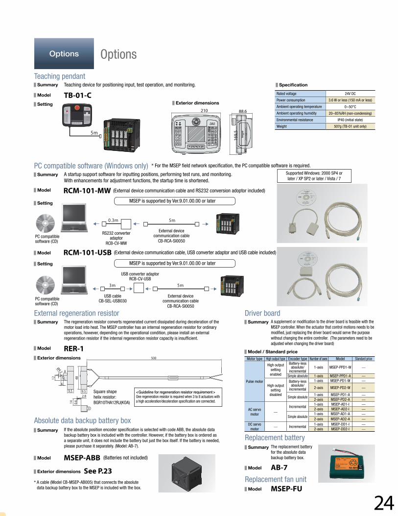
Teaching pendant
PC compatible software (Windows only)
External regeneration resistor
Absolute data backup battery box
Replacement battery
Replacement fan unit
Driver board
Summary
Model
Setting
Summary
Model
Setting
Summary
Summary
Summary
Model
Model
Summary
Model / Standard price
Model
Setting
Model
Exterior dimensions
Exterior dimensions
SpecificationTeaching device for positioning input, test operation, and monitoring.
A startup support software for inputting positions, performing test runs, and monitoring. With enhancements for adjustment functions, the startup time is shortened.
The regeneration resistor converts regenerated current dissipated during deceleration of the motor load into heat. The MSEP controller has an internal regeneration resistor for ordinary operations, however, depending on the operational condition, please install an external regeneration resistor if the internal regeneration resistor capacity is insufficient.
If the absolute position encoder specification is selected with code ABB, the absolute data backup battery box is included with the controller. However, if the battery box is ordered as a separate unit, it does not include the battery but just the box itself. If the battery is needed, please purchase it separately. (Model: AB-7). The replacement battery
for the absolute data backup battery box.
A supplement or modification to the driver board is feasible with the MSEP controller. When the actuator that control motions needs to be modified, just replacing the driver board would serve the purpose without changing the entire controller. (The parameters need to be adjusted when changing the driver board)
* For the MSEP field network specification, the PC compatible software is required.
PC compatible software (CD)
PC compatible software (CD)
External device communication cable
CB-RCA-SI0050
External device communication cable
CB-RCA-SI0050
RS232 converter adaptor
RCB-CV-MW
USB converter adaptorRCB-CV-USB
Square shape helix resistor: BGR10THA12RJ(KOA)
<Guideline for regeneration resistor requirement >One regeneration resistor is required when 3 to 8 actuators with a high acceleration/deceleration specification are connected.
USB cableCB-SEL-USB030
Supported Windows: 2000 SP4 or later / XP SP2 or later / Vista / 7
(External device communication cable and RS232 conversion adoptor included)
(External device communication cable, USB converter adaptor and USB cable included)
(Batteries not included)
* A cable (Model CB-MSEP-AB005) that connects the absolute data backup battery box to the MSEP is included with the box.
TB-01-C
RCM-101-MW
RCM-101-USB
RER-1
MSEP-ABBAB-7
MSEP-FU
See P.23
Rated voltage 24V DC
Power consumption 3.6 W or less (150 mA or less)
Ambient operating temperature 0~50°C
Ambient operating humidity 20~85%RH (non-condensing)
Environmental resistance IP40 (initial state)
Weight 507g (TB-01 unit only)
MSEP is supported by Ver.9.01.00.00 or later
MSEP is supported by Ver.9.01.00.00 or later
Motor type High output type Encoder type Number of axes Model Standard price
Pulse motor
High outputsetting enabled
Battery-less absolute/
incremental1-axis MSEP-PPD1-W —
Simple absolute 1-axis MSEP-PPD1-A —
High output setting
disabled
Battery-less absolute/
incremental
1-axis MSEP-PD1-W —
2-axis MSEP-PD2-W —
Simple absolute 1-axis MSEP-PD1-A —2-axis MSEP-PD2-A —
AC servo motor
—Incremental
1-axis MSEP-AD1-I —2-axis MSEP-AD2-I —
Simple absolute1-axis MSEP-AD1-A —2-axis MSEP-AD2-A —
DC servo motor
— Incremental1-axis MSEP-DD1-I —2-axis MSEP-DD2-I —
210 88.6
169.
5
Model
Exterior dimensions
Options Options

25
Service Parts MSEPseries
(Front view)
(Front view)
(Front view)
(Front view)
(Front view)
(Front view)
Actuator side
Actuator side
Actuator side
Actuator side1-1827863-1
(AMP)
Controller side
Controller side
Controller side
Controller sidePADP-24V-1-S
(JST)
Minimum bending radius
* The robot cable is designed for flex-resistance: Please use the robot cable if the cable has to be installed through the cable track.
* The robot cable is designed for flex-resistance: Please use the robot cable if the cable has to be installed through the cable track.
(Note 1) If the cable is 5m or longer, Ø9.1 cable diameter applies for a non-robot cable and Ø10 for a robot cable.
(Note 1) If the cable is 5m or longer, Ø9.1 cable diameter applies for a non-robot cable and Ø10 for a robot cable.
(Note 1)(N
ote 1
)
* Please indicate cable length (L) in , maximum 20m. e.g.) 080=8m
* Please indicate cable length (L) in , maximum 20m. e.g.) 080=8m
* Please indicate cable length (L) in , maximum 20m. e.g.) 080=8m
5m or less length R = 68mm or more (Dynamic bending condition) Longer than 5m R = 73mm or more (Dynamic bending condition)
Pin No Signal name3 ØA5 VMM10 ØB9 VMM4 Ø_A15 Ø_B8 LS+14 LS-12 SA[mABS]17 SB[mABS]1 A+6 A-11 B+16 B-20 BK+2 BK-21 VCC7 GND18 VPS13 LS_GND19 —22 —(CFvcc)23 —24 FG
Pin No Signal nameA1 ØA/UB1 VMM/VA2 Ø A/WB2 ØB/-A3 VMM/-B3 Ø_B/-A4 LS+/BK+B4 LS-/BK-A6 -/A+B6 -/A-A7 A+/B+B7 A-/B-A8 B+/Z+B8 B-/Z-A5 BK+/LS+B5 BK-/LS-A9 LS_GNDB9 VPSA10 VCCB10 GNDA11 —B11 FG
Actuator side
Pin numberA1B1A2B2A3B3A4B4A6B6A7B7A8B8A5B5A9B9A10B10A11B11
Controller side
Pin number125346781112131415169102018171921242223
Pin No Signal name1 ØA2 VMM3 ØB4 VMM5 Ø_A6 Ø_B7 LS+8 LS-
11 SA[mABS]12 SB[mABS]13 A+14 A-15 B+16 B-9 BK+
10 BK-17 VCC19 GND18 VPS20 LS_GND22 —21 —(CFvcc)23 —24 FG
Pin No Signal name1 Ø A/U2 VMM/V5 Ø_A/W3 ØB/-4 VMM/-6 Ø_B/-7 LS+/BK+8 LS-/BK-
11 -/A+12 -/A-13 A+/B+14 A-/B-15 B+/Z+16 B-/Z-9 BK+/LS+
10 BK-/LS-20 LS_GND18 VPS17 VCC19 GND21 —22 —23 —24 FG
[PCON](ACON)[ ΦA] (U)
[VMM] (V)[ Φ/A ] (W)[ ΦB ] ( - )
[VMM] ( - )[ Φ/B ] ( - )
[LS+] (BK+)[LS-] (BK-)[ - ] (A+)[ - ] (A-)
[ A+ ] (B+)[ A- ] (B-)
[ B+ ] (Z+)[ B- ] (Z-)
[BK+] (LS+)[BK-] (LS-)
[GNDLS] (GNDLS)[VPS] (VPS)[VCC] (VCC)[GND] (GND)
NCShield [FG] (FG)
NCNC
Modelnumber
CB-CAN-MPA Integrated Motor-Encoder Cable forRCP5/RCDCB-CAN-MPA -RB Integrated Motor-Encoder Robot Cable
Modelnumber
CB-CA-MPA Integrated Motor-Encoder Cable for RCP4CB-CA-MPA -RB Integrated Motor-Encoder Robot Cable
Modelnumber
CB-APSEP-MPA - LC Integrated Motor-Encoder Cable for RCP3/RCA2 and othersCB-APSEP-MPA Integrated Motor-Encoder Robot Cable
* The robot cable is designed for flex-resistance: Please use the robot cable if the cable has to be installed through the cable track.
Minimum bending radius 5m or less length R = 68mm or more (Dynamic bending condition) Longer than 5m R = 73mm or more (Dynamic bending condition)
Minimum bending radius R = 68mm or more (Dynamic bending condition)
ServiceParts Service Parts
26
(Front view)
(Front view)
Actuator side
Actuator side
* Please indicate cable length (L) in , maximum 20m. e.g.) 080=8m* Only robot cable is available for this model.
* Please indicate cable length (L) in , maximum 20m. e.g.) 080=8m* Only robot cable is available for this model.
* Please indicate cable length (L) in , maximum 10m. e.g.) 080=8m
Actuator side
Pin numberA1B1A2B2A3B3A6B6A7B7A8B8A4B4A5B5A9B9A10B10A11B11
Actuator side
Pin number12
3
181771612341011141315658129
No. Cable color WiringA18 Gray-2
Flat cable (pressure- welded)
A19 White-2A20 Black-2A21 Brown-3A22 Red-3A23 Orange-3A24 Yellow-3A25 Green-3A26 Blue-3A27 Purple-3A28 Gray-3A29 White-3A30 Black-3A31 Brown-4A32 Red-4A33 Orange-4A34 Yellow-4
No. Signal name Cable color WiringA1 24V Brown-1
Flat cable (pressure- welded)
A2 24V Red-1A3 — Orange-1A4 Yellow-1A5 IN0 Green-1A6 IN1 Blue-1A7 IN2 Purple-1A8 IN3 Gray-1A9 IN4 White-1A10 IN5 Black-1A11 IN6 Brown-2A12 IN7 Red-2A13 IN8 Orange-2A14 IN9 Yellow-2A15 IN10 Green-2A16 IN11 Blue-2A17 IN12 Purple-2A18 IN13 Gray-2A19 IN14 White-2A20 IN15 Black-2
No. Cable color WiringB18 Gray-6
Flat cable (pressure- welded)
B19 White-6B20 Black-6B21 Brown-7B22 Red-7B23 Orange-7B24 Yellow-7B25 Green-7B26 Blue-7B27 Purple-7B28 Gray-7B29 White-7B30 Black-7B31 Brown-8B32 Red-8B33 Orange-8B34 Yellow-8
No. Cable color WiringA1 Brown-1
Flat cable (pressure- welded)
A2 Red-1A3 Orange-1A4 Yellow-1A5 Green-1A6 Blue-1A7 Purple-1A8 Gray-1A9 White-1
A10 Black-1A11 Brown-2A12 Red-2A13 Orange-2A14 Yellow-2A15 Green-2A16 Blue-2A17 Purple-2
No. Cable color WiringB1 Brown-5
Flat cable (pressure- welded)
B2 Red-5B3 Orange-5B4 Yellow-5B5 Green-5B6 Blue-5B7 Purple-5B8 Gray-5B9 White-5
B10 Black-5B11 Brown-6B12 Red-6B13 Orange-6B14 Yellow-6B15 Green-6B16 Blue-6B17 Purple-6
No. Signal name Cable color WiringB1 OUT0 Brown-3
Flat cable (pressure- welded)
B2 OUT1 Red-3B3 OUT2 Orange-3B4 OUT3 Yellow-3B5 OUT4 Green-3B6 OUT5 Blue-3B7 OUT6 Purple-3B8 OUT7 Gray-3B9 OUT8 White-3
B10 OUT9 Black-3B11 OUT10 Brown-4B12 OUT11 Red-4B13 OUT12 Orange-4B14 OUT13 Yellow-4B15 OUT14 Green-4B16 OUT15 Blue-4B17 — Purple-4B18 Gray-4B19 0V White-4B20 0V Black-4
Controller side
Pin number1253467813141516——9102018171921242223
Controller side
Pin number123456789
101112131415161718192021222324
[ ΦA ][ VMM ][ Φ/A ][ ΦB ]
[ VMM ][ Φ/B ][ LS+ ][ LS- ][ A+ ][ A- ][ B+ ][ B- ]
NCNC
[BK+][BK-]
[GNDLS][VPS][VCC][GND]
NCShield [ FG ] (FG)
NCNC
[ U ][ V ]NCNC
[ W ]NC
[ BK+ ][ BK- ][ LS+ ][ LS- ][ A+ ][ A- ][ B+ ][ B- ][ Z+ ][ Z- ][VCC][VPS][GND]
[Spare]NCNCNC
Shield [ FG ]
Minimum bending radius R = 68mm or more (Dynamic bending condition)
A
A
B
B
Flat cable
Flat cable
Flat cable (34-core) x 2
Flat cable (20-core) x 2
Connector: HIF6-068D-1.27R
Half-pitch MIL socket: HIF6-40D-1.27R (Hirose)
HIF6-068D-1.27R
HIF6-40D-1.27R
No connector
No connector
No connector
No connector
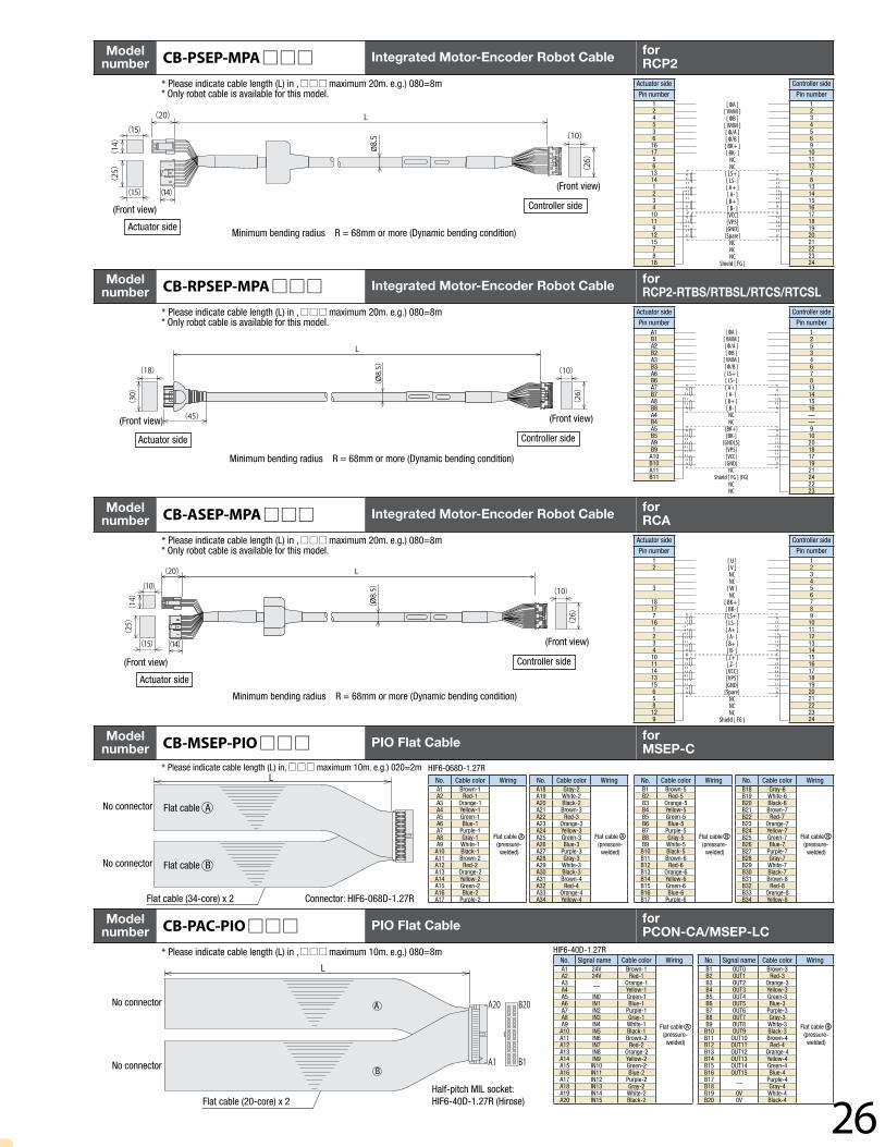
Modelnumber CB-RPSEP-MPA Integrated Motor-Encoder Robot Cable for
RCP2-RTBS/RTBSL/RTCS/RTCSL
Modelnumber CB-ASEP-MPA Integrated Motor-Encoder Robot Cable for
RCA
Modelnumber CB-MSEP-PIO PIO Flat Cable for
MSEP-C* Please indicate cable length (L) in, maximum 10m. e.g.) 020=2m
Modelnumber CB-PAC-PIO PIO Flat Cable for
PCON-CA/MSEP-LC
Minimum bending radius R = 68mm or more (Dynamic bending condition)
(Front view)
Actuator side
Controller side
* Please indicate cable length (L) in , maximum 20m. e.g.) 080=8m* Only robot cable is available for this model.
Minimum bending radius R = 68mm or more (Dynamic bending condition)
Actuator side
Pin number124536161756131412341011912157818
Controller side
Pin number123456910111278131415161718192021222324
[ ΦA ][ VMM ]
[ ΦB ][ VMM ][ Φ/A ][ Φ/B ][ BK+ ][ BK- ]
NCNC
[ LS+ ][ LS- ][ A+ ][ A- ][ B+ ][ B- ][VCC][VPS][GND]
[Spare]NCNCNC
Shield [ FG ]
Modelnumber CB-PSEP-MPA Integrated Motor-Encoder Robot Cable for
RCP2
(Front view)
Controller side
(Front view)
Controller side
(Front view)

IAI America, Inc.Headquarters: 2690 W. 237th Street, Torrance, CA 90505 (800) 736-1712Chicago Office: 110 E. State Pkwy, Schaumburg, IL 60173 (800) 944-0333Atlanta Office: 1220 Kennestone Circle, Suite 108, Marietta, GA 30066 (888) 354-9470
www.intelligentactuator.com
IAI Industrieroboter GmbHOber der Röth 4, D-65824 Schwalbach am Taunus, Germany
IAI Robot (Thailand), CO., Ltd.825 PhairojKijja Tower 12th Floor, Bangna-Trad RD.,Bangna, Bangna, Bangkok 10260, Thailand
The information contained in this product brochure may change without prior notice due to product improvements.
CJ0216-2A-UST-1-0215


