
Version 2003
MSC.Marc Mentat
• •
Help Reference

Copyright 2003 MSC.Software Corporation
All rights reserved. Printed in U.S.A.
Corporate Europe
MSC.Software Corporation MSC.Software GmbH2 MacArthur Place Am MoosfeldSanta Ana, CA 92707 81829 München, GERMANYTelephone: (714) 540-8900 Telephone: (49) (89) 431 987 0Fax: (714) 784-4056 Fax: (49) (89) 436 1716
Asia Pacific Worldwide WebMSC Japan Ltd. www.mscsoftware.comEntsuji-Gadelius Building2-39, Akasaka 5-chomeMinato-ku, Tokyo 107-0052, JAPANTelephone: (81) (3) 3505 0266Fax: (81) (3) 3505 0914
Part Number: MA*V2003*Z*Z*Z*DC-REF
Disclaimer
THE CONCEPTS, METHODS, AND EXAMPLES PRESENTED IN THE DOCUMENTATION ARE FOR ILLUSTRATIVE AND EDUCATIONAL PURPOSES ONLY, AND ARE NOT INTENDED TO BE EXHAUSTIVE OR TO APPLY TO ANY PARTICULAR ENGINEERING PROBLEM OR DESIGN. USER ASSUMES ALL RISKS AND LIABILITY FOR RESULTS OBTAINED BY THE USE OF THE COMPUTER PROGRAMS DESCRIBED HEREIN. IN NO EVENT SHALL MSC.SOFTWARE CORPORATION BE LIABLE TO ANYONE FOR ANY SPECIAL, COLLATERAL, INCIDENTAL, INDIRECT OR CONSEQUENTIAL DAMAGES ARISING OUT OF, RESULTING FROM, OR IN CONNECTION WITH USE OF THE CONTENTS OR INFORMATION IN THE DOCUMENTATION.
MSC.SOFTWARE CORPORATION ASSUMES NO LIABILITY OR RESPONSIBILITY FOR ANY ERRORS THAT MAY APPEAR IN THE DOCUMENTATION. THE DOCUMENTATION IS PROVIDED ON AN “AS-IS” BASIS AND ALL EXPRESS AND IMPLIED CONDITIONS, REPRESENTATIONS AND WARRANTIES, INCLUDING ANY IMPLIED WARRANTY OF MERCHANTABILITY OR FITNESS FOR A PARTICULAR PURPOSE, ARE DISCLAIMED, EXCEPT TO THE EXTENT THAT SUCH DISCLAIMERS ARE HELD TO BE LEGALLY INVALID.
MSC.SOFTWARE CORPORATION RESERVES THE RIGHT TO MAKE CHANGES IN SPECIFICATIONS AND OTHER INFOR-MATION CONTAINED IN THE DOCUMENTATION WITHOUT PRIOR NOTICE.
Trademarks
MSC, Dytran, MARC, and Patran are registered trademarks of MSC.Software Corporation or its subsidiaries in the United States and/or other countries. MSC., MSC.Dytran, MSC.Marc, and MSC.Patran are trademarks of MSC.Software Corporation.
NASTRAN is a registered trademark of the National Aeronautics and Space Administration. MSC.Nastran is an enhanced proprietary version developed and maintained by MSC.Software Corporation. All other trademarks are the property of their respective owners.
Third Party Software Program Credits
METIS is copyrighted by the regents of the University of Minnesota.NT-MPICH is developed by Lehrstuhl für Betriebssysteme der RWTH Aachen. Copyright 1992-2003 Lehrstuhl für Betriebssysteme der RWTH Aachen.
Government UseUse, duplication, or disclosure by the U.S. Government is subject to restrictions as set forth in FAR 12.212 (Commercial Computer Software) and DFARS 227.7202 (Commercial Computer Software and Commercial Computer Software Documentation), as applicable.

Contents
C O N T E N T SMSC.Marc Mentat Help Reference
Chapter 1Mechanics of MSC.Marc Mentat
■ Chapter Overview, 2
■ MSC.Marc Mentat Window Layout, 3
■ How MSC.Marc Mentat Communicates with You, 4
■ How You Communicate with MSC.Marc Mentat, 5❑ The Mouse, 5❑ Keyboard Input, 7
■ Menu Structure, 10❑ Menu System, 10❑ Buttons, 12
■ List Specification, 15
■ Identifiers, 23
Chapter 2Main Menu ■ Main Menu Overview, 2
■ Preprocessing Menus, 3
■ Analysis Menus, 5
■ Postprocessing Menus, 6
■ Configuration Menus, 6
■ Quit Command, 6
■ Static Menus, 6
■ Utilities Menus, 7❑ PostScript®, 8❑ Utilities Continued, 10❑ Utilities, More Menu, 12
■ Files Menu, 15❑ Model, 15
MSC.Marc Mentat Help Reference
iv
❑ Interfaces, 17❑ MSC.Marc Input File, 18
■ Plot Menu, 21
■ View Menu, 22
■ Static Commands, Continued, 23
■ List Commands, 25
ACommands Begin with A ■ Mentat Help Commands in A, 1
BCommands Begin with B ■ Mentat Help Commands in B, 75
CCommands Begin with C ■ Mentat Help Commands in C, 83
DCommands Begin with D ■ Mentat Help Commands in D, 193
ECommands Begin with E ■ Mentat Help Commands in E, 231
FCommands Begin with F ■ Mentat Help Commands in F, 267
GCommands Begin with G ■ Mentat Help Commands in G, 281
Contents v
HCommands Begin with H ■ Mentat Help Commands in H, 299
ICommands Begin with I ■ Mentat Help Commands in I, 313
JCommands Begin with J ■ Mentat Help Commands in J, 355
KCommands Begin with K ■ Mentat Help Commands in K, 437
LCommands Begin with L ■ Mentat Help Commands in L, 439
MCommands Begin with M ■ Mentat Help Commands in M, 537
NCommands Begin with N ■ Mentat Help Commands in N, 631
OCommands Begin with O ■ Mentat Help Commands in O, 659
PCommands Begin with P ■ Mentat Help Commands in P, 669
QCommands Begin with Q ■ Mentat Help Commands in Q, 727
MSC.Marc Mentat Help Reference
vi
RCommands Begin with R ■ Mentat Help Commands in R, 729
SCommands Begin with S ■ Mentat Help Commands in S, 823
TCommands Begin with T ■ Mentat Help Commands in T, 999
UCommands Begin with U ■ Mentat Help Commands in U, 1041
VCommands Begin with V ■ Mentat Help Commands in V, 1075
WCommands Begin with W ■ Mentat Help Commands in W, 1087
XCommands Begin with X ■ Mentat Help Commands in X, 1089
YCommands Begin with Y ■ Mentat Help Commands in Y, 1116
ZCommands Begin with Z ■ Mentat Help Commands in Z, 1117

Contents vii
Appendix AMSC.Marc Mentat Arithmetic and Database Functions
■ Arithmetic and Database Functions, 2❑ Arithmetic Functions, 2❑ Database Functions, 4❑ Post File Database Functions, 7❑ Set Functions, 8

MSC.Marc Mentat Help Reference
viii
Chapter 1: Mechanics of Mentat
CHAPTER
1 Mechanics of MSC.Marc Mentat
■ MSC.Marc Mentat Window Layout
■ How MSC.Marc Mentat Communicates with You
■ How You Communicate with MSC.Marc Mentat
■ Menu Structure
■ List Specification
■ Identifiers

Chapter Overview MSC.Mentat Help ReferenceChapter 1: Mechanics of MSC.Marc Mentat
1-2
Chapter OverviewThis Help Reference manual will provide you with a description of the commands associated with the Mentat Product. The information is provided in a logical manner based upon the menu layout. This manual gives a description of the menu buttons. Associated with each button is a Mentat command. These commands are displayed in the scroll area, and may optionally be typed in. You should note that the commands may be executed at any point in the Mentat session.
There are fundamentally two types of commands:
– Those which set parameters or values such as entering the number of subdivisions.
– Those which result in an action such as actually subdividing the mesh or removing an entity.
In either case, the database associated with the problem is altered. In the case of defining a parameter, if an incorrect value is defined, simply enter a new value. In the case that an unanticipated result occurred due to the action, use the UNDO command to recover the previous state of the database.
This manual is referential in nature. The results of a command are graphically depicted in a few sections. The MSC.Marc User’s Guide should be use to learn how to be proficient with the product.
Upon completion of this chapter, you should have a clearer understanding of the following areas:
• The basic window layout
• How Mentat communicates with you
• How you communicate with Mentat
• The menu system

1-3MSC.Mentat Help Reference MSC.Marc Mentat Window LayoutChapter 1: Mechanics of MSC.Marc Mentat
MSC.Marc Mentat Window LayoutThe starting point for all communication with Mentat is the window shown in Figure 1-1 that appears at the start of the program.
Figure 1-1 Basic Mentat Window
The Mentat window that appears on your screen is divided into three major areas:
• Graphics
• Menu
• Dialogue
The graphics area is used to display the current state of the database. When you start Mentat, the graphics area is blank to indicate that the database is empty.
The menu area is reserved to show the selectable menu-items and is divided into two sub-areas, the static and dynamic menus. The contents of the dynamic menu area change as the menu-items are selected. In contrast, the static menu is always present and contains items that are applicable and selectable at all times.
The dialogue area is a scrollable area of about five visible lines where all program prompts, warnings, and responses appear, and where the user can input data or commands. Within the dialogue area is the status area which is reserved to communicate the state of the program to the user. Either working or ready appears in the status area to reflect the current state of the program.
GraphicsDynamicMenu
Static Menu
Dialogue Status
How MSC.Marc Mentat Communicates with You MSC.Mentat Help ReferenceChapter 1: Mechanics of MSC.Marc Mentat
1-4
How MSC.Marc Mentat Communicates with YouMentat communicates with you via prompts and messages and other visual queues.
Mentat’s prompts urge you to take action through the input of data or commands. These prompts have 3 types of trailing punctuation marks to indicate the required type of input:
: enter numeric data;
> enter a character string, typically a command, file name or set name;
? enter a YES or NO answer.
If you misspell a keyword or enter an incorrect response, Mentat warns you through a message posted in the dialogue area. Mentat does not require that you complete every action you initiate. For example, if you are prompted for a filename, and you change your mind, entering a <CR> instead of typing in the filename will tell Mentat to abort the action. If the program is waiting for a list of items to operate on, and instead you enter a command that also requires a list of items or any additional data, Mentat will ignore your original request and process the command. If the command you enter does not request additional data, you are returned to the original data request from before the interrupt.
The program assumes at all times that you want to repeat the previous operation on a new set of items and will prompt you for a new list to operate on. This process repeats itself until you indicate otherwise, typically by entering a new command or a <CR>.
1-5MSC.Mentat Help Reference How You Communicate with MSC.Marc MentatChapter 1: Mechanics of MSC.Marc Mentat
How You Communicate with MSC.Marc MentatAll interaction with Mentat is done through the mouse, keyboard, or a combination of both. This section first discusses the usage of the mouse, followed by a discussion on how to use the keyboard as a means to enter commands and data.
The Mouse
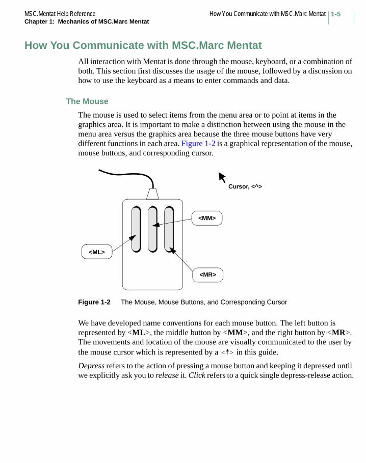
The mouse is used to select items from the menu area or to point at items in the graphics area. It is important to make a distinction between using the mouse in the menu area versus the graphics area because the three mouse buttons have very different functions in each area. Figure 1-2 is a graphical representation of the mouse, mouse buttons, and corresponding cursor.
Figure 1-2 The Mouse, Mouse Buttons, and Corresponding Cursor
We have developed name conventions for each mouse button. The left button is represented by <ML>, the middle button by <MM>, and the right button by <MR>. The movements and location of the mouse are visually communicated to the user by the mouse cursor which is represented by a in this guide.
Depress refers to the action of pressing a mouse button and keeping it depressed until we explicitly ask you to release it. Click refers to a quick single depress-release action.
Cursor, <^>
<MM>
<MR>
<ML>
< >

How You Communicate with MSC.Marc Mentat MSC.Mentat Help ReferenceChapter 1: Mechanics of MSC.Marc Mentat
1-6
Using the Mouse to Select a Menu Item
To select a menu item with the mouse, move the over the item that you want to select and click the <ML>. To return to the previous menu, move the over the menu area, and click the <MR>. Alternatively, you can click on the RETURN button in the menu area using <ML>. Clicking on the MAIN button takes you to the main menu.
On-line Help
An important companion for novice users in Mentat is the on-line help feature. Each menu item has a help panel with a short description and explanation of the function of that menu item. To activate the help feature, position the over the menu item on which you require help, followed by a click of the <MM>. The help panel disappears the moment you select another menu item.
Using the Mouse to Point
The mouse is used in two ways to operate in the graphics area: to point to, or pick, existing items as well as to point to, or pick, the location of yet to be created items.
1. The need to identify existing items displayed in the graphics area occurs frequently during a user’s interaction with the Mentat program. The mouse is used for this by moving the over the item to be identified followed by a click of the <ML>. In the remainder of the manual we describe this action by clicking on an item. If you inadvertently click on an item, you can undo that action by clicking the <MM> anywhere in the graphics area.
Figure 1-3 Using the Mouse in the Menu Area
< >
< >
< >
< >
<ML>Use this button,
for command selection
<MR>for RETURN
Use this button,
<MM>for on-line help
Use this button,

1-7MSC.Mentat Help Reference How You Communicate with MSC.Marc MentatChapter 1: Mechanics of MSC.Marc Mentat
At times, you will need to identify more than a single item. A list of items must be terminated by a click of the <MR> with the positioned anywhere in the graphics area. Alternatively, you can click on the END LIST button in the menu area using <ML>.
2. In order to use the mouse for creating a new item you need to define the relation between the position on the graphics screen and its location in global coordinates. In Mentat, it is possible to define a grid that is positioned in space and where the grid consists of points that can be pointed to. If you click in the vicinity of a grid point, the coordinates of the item that you created will be snapped to that grid point. In addition, you can also pick an existing node, point, or surface-grid-point to specify a location.
Figure 1-4 Using the Mouse in the Graphics Area
Keyboard Input
Not all data can be entered through the mouse; numerical and literal data must be entered via the keyboard. The program mode prescribes the specific requirements for proper entry of each type of data. The program can be in data mode or in command/literal data mode and is described under the following two headings.
Numerical Data
You must use the keyboard for numerical data entry. The program interprets the data entry according to the context in which it is used. If the program expects a real number and you enter an integer, Mentat will automatically convert the number to its floating point value. Conversely, if a floating point format number is entered where an integer is expected, the program will convert the real number to an integer.
< >
<ML>Use this button,
to pick
<MR>for end of item list
Use this button,
<MM>to undo last pick
Use this button,

How You Communicate with MSC.Marc Mentat MSC.Mentat Help ReferenceChapter 1: Mechanics of MSC.Marc Mentat
1-8
Scientific notation for real numbers is allowed in the following formats:
.12345e01
.12345e01
-0.12345e-01
The interpreter does not allow imbedded blanks in the format. Whenever the program encounters an illegal format, the message bad float! will appear in the dialogue area. The prompt for numerical data is a colon (:).
Literal Data
Literal data is used for file, set and macro names. A literal data string may not be abbreviated. Commands as introduced in the beginning on page 4 are considered string data (as opposed to literal string data) and can be abbreviated as long as the character string is unique within the Mentat command library. For example, *add_elements cannot be abbreviated to *add because of the other commands that start with the same characters such as *add_nodes and *add_curves. The program checks the input for validity against the internal library of valid responses. For example, if you enter an ambiguous or misspelled command, Mentat responds by listing all the valid entries that start with the same first letter of the command. The prompt for literal data is a greater-than symbol (>).
If the program is in data mode which is identified by the : prompt, you must enter a command preceded by an * (asterisk) to instruct the program that you are entering a command.
For example: Enter node (1): *add_nodes
If you enter a command without the asterisk when the program is in data mode, Mentat responds with an error message in the dialogue area.
The asterisk can be omitted when the program is in command or literal data mode which is indicated by the greater-than symbol (>).
For example: Command > add_nodes
Editing the Input Line
The experienced user can enter a sequence of commands or requests in a single 160- column input line. Note that anything typed beyond the input line limit is lost! Use <CR> to avoid this. You must use a blank space to separate entries when you are entering multiple responses on a single input line. All entries in the buffer are processed sequentially.

1-9MSC.Mentat Help Reference How You Communicate with MSC.Marc MentatChapter 1: Mechanics of MSC.Marc Mentat
Mentat maintains a history of lines that are entered and offers limited recall and editing capabilities for the command line. The arrow keys ∧ and ∨ on the keyboard can be used to scroll up and down in the dialogue area to make these lines visible. Use CTRL-p (that is, hold down the CTRL key and press the p key) to recall a previously entered input line. Repeat the CTRL-p sequence to recall as many lines as you need. Use CTRL-n to move to the next line in the history of command lines. (By the way, p and n stand for previous and next respectively in these control sequences.)
Edit functions for the current line are: backspace for character delete and CTRL-u for line delete. The left and right arrow keys are used to position the cursor at the desired location to overwrite or insert characters. The TAB key is used as a toggle to switch from insert to overwrite mode and vice versa. For example, if you type *view_viewpont 0.0 0.0 1.0, the program responds with the message unknown command in the dialogue area. To correct the entry, recall the line using CTRL-p, use the left arrow key to move the cursor to the letter n of view_viewpont, press the TAB key, type i, and press <CR> to enter the line. The command will now be *view_viewpoint.

Menu Structure MSC.Mentat Help ReferenceChapter 1: Mechanics of MSC.Marc Mentat
1-10
Menu StructureThis section focuses on the menu system as a means to communicate with Mentat. The first sub-section discusses the structure of menus that constitute the program. The second sub-section analyzes the components of each menu.
Menu System
The kernel of the Mentat program consists of a set of processors in a parallel configuration that operate on the database. The database is the most compact, yet complete, description of the current state of the model you are analyzing. Typical examples of processors are SUBDIVIDE and PATH PLOT.
Every processor may depend on a number of parameters that influence the process. The combined number of processors and parameters in Mentat is too large to show in one menu. To help you in the scheduling of tasks, we have structured menus around the processors that lead you through the steps from top down. Figure 1-1 shows you the organization of the main menu that appears when you start Mentat and how it corresponds to the main tasks of the analysis cycle depicted in Figure 1-1 of this chapter.
For your convenience, the menu items have been grouped in panels by the four main tasks: preprocessing, analysis, postprocessing, and configuration. The menu items and sub-tasks on each of these panels represent yet another group of corresponding tasks. It is important to realize that most of the menus for the global tasks do not contain processors; these menus are for navigation purposes only and are not part of the kernel of the program!
1-11MSC.Mentat Help Reference Menu StructureChapter 1: Mechanics of MSC.Marc Mentat
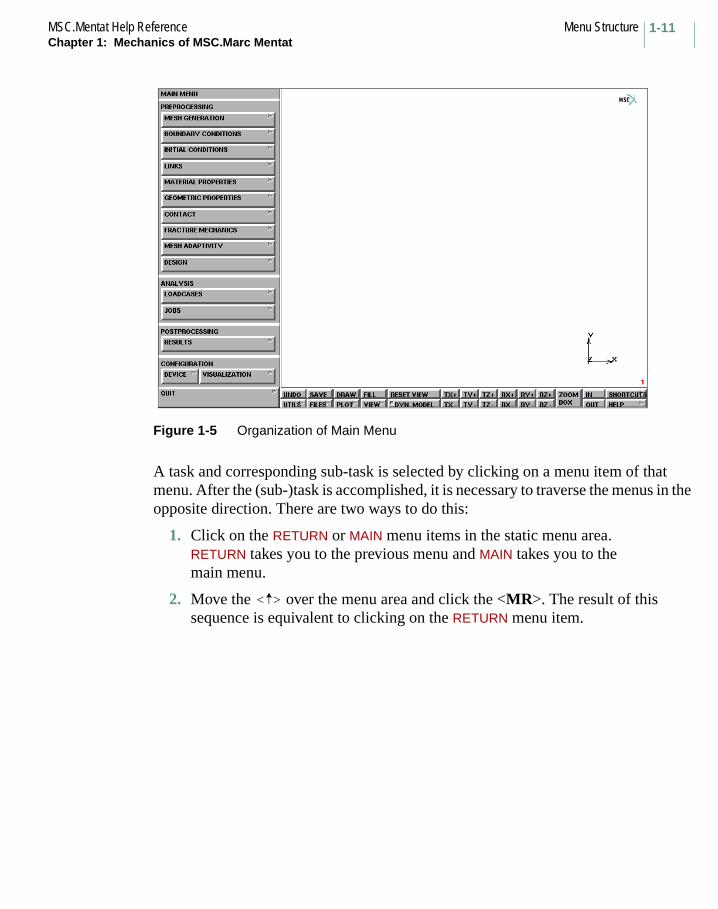
Figure 1-5 Organization of Main Menu
A task and corresponding sub-task is selected by clicking on a menu item of that menu. After the (sub-)task is accomplished, it is necessary to traverse the menus in the opposite direction. There are two ways to do this:
1. Click on the RETURN or MAIN menu items in the static menu area.RETURN takes you to the previous menu and MAIN takes you to the main menu.
2. Move the over the menu area and click the <MR>. The result of this sequence is equivalent to clicking on the RETURN menu item.
< >
Menu Structure MSC.Mentat Help ReferenceChapter 1: Mechanics of MSC.Marc Mentat
1-12
Buttons
Positioned on the panel are flat and raised rectangles. The raised rectangles in the released state suggest a light shining directly from above. The task is printed on the raised rectangle and is selectable by clicking on it with the <ML>. Flat rectangles are not selectable; they convey the setting of parameters. The program does not respond to clicking the <ML> or <MM> on the flat rectangles.
Mentat contains 5 types of raised rectangles. Throughout the remainder of this document we will use the term button for raised rectangle. Below is a list of the different types of buttons and their functions.
The Submenu Button
As mentioned before, this button represents a gateway to a submenu. It is recognized by a ( ) symbol on the right hand side of the button.
The Cycle Button
A cycle button ( ) is used to set a parameter to a value when there is a choice of three or more alternatives. The parameter is set to the value that is currently displayed on the button. Clicking on this button will change the displayed value to the next consecutive value in the list of alternatives. If the list is exhausted, the process will start over again with the first alternative. Note that the symbol is indicative of the unidirectional way the list of alternatives is traversed.
The Toggle Button
A special type of cycle button is the toggle button ( ) where the number of alternatives is limited to two. It is a switch that connotates a state of on or off; a button is depressed to flag on or active, and released (or raised) to flag that the listed parameter is off or inactive.
The Tabular Button
A tabular button represents a combination of a parameter button and a flat rectangle. They show one or more numerical or alpha-numerical values that are associated with the parameter represented by the button. Clicking on this button type usually implies that you have to enter data through the keyboard, which is then displayed in the rectangular fields after the keyboard input is completed.
Tabular buttons may contain a large number of numerical data fields. There are instances where the tabular buttons pop-up over the graphics area. If this is the case, you need to confirm that all entries have been completed by clicking on the OK button. Before returning to regular menu selection, you can clear all entries by clicking on the RESET button which usually appears in the lower left hand side of the panel. The
1-13MSC.Mentat Help Reference Menu StructureChapter 1: Mechanics of MSC.Marc Mentat
pop-up table then disappears from the graphics area and the original graphics area is restored. Typical examples of these compounded tabular buttons can be found in the boundary conditions and material properties menus.
The One-Only Button Group
The alternative values of cycle buttons are also represented as individual toggles under a one-only button group. In a cycle, only one value can be selected, hence if a button in a one-only group of buttons is depressed, another is released. The one-only button sequence is identified by a symbol shown on each button of that sequence.
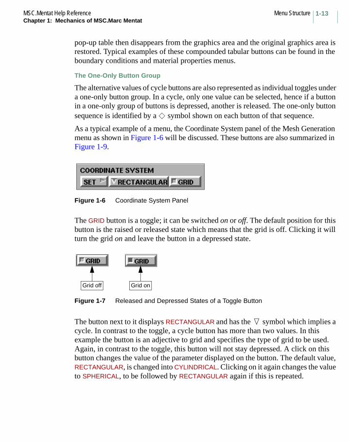
As a typical example of a menu, the Coordinate System panel of the Mesh Generation menu as shown in Figure 1-6 will be discussed. These buttons are also summarized in Figure 1-9.
Figure 1-6 Coordinate System Panel
The GRID button is a toggle; it can be switched on or off. The default position for this button is the raised or released state which means that the grid is off. Clicking it will turn the grid on and leave the button in a depressed state.
Figure 1-7 Released and Depressed States of a Toggle Button
The button next to it displays RECTANGULAR and has the symbol which implies a cycle. In contrast to the toggle, a cycle button has more than two values. In this example the button is an adjective to grid and specifies the type of grid to be used. Again, in contrast to the toggle, this button will not stay depressed. A click on this button changes the value of the parameter displayed on the button. The default value, RECTANGULAR, is changed into CYLINDRICAL. Clicking on it again changes the value to SPHERICAL, to be followed by RECTANGULAR again if this is repeated.
Grid off Grid on
Menu Structure MSC.Mentat Help ReferenceChapter 1: Mechanics of MSC.Marc Mentat
1-14
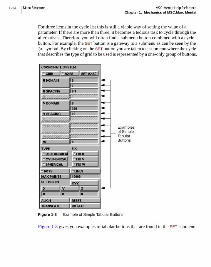
For three items in the cycle list this is still a viable way of setting the value of a parameter. If there are more than three, it becomes a tedious task to cycle through the alternatives. Therefore you will often find a submenu button combined with a cycle button. For example, the SET button is a gateway to a submenu as can be seen by the
symbol. By clicking on the SET button you are taken to a submenu where the cycle that describes the type of grid to be used is represented by a one-only group of buttons.
Figure 1-8 Example of Simple Tabular Buttons
Figure 1-8 gives you examples of tabular buttons that are found in the SET submenu.
Examplesof SimpleTabularButtons

1-15MSC.Mentat Help Reference List SpecificationChapter 1: Mechanics of MSC.Marc Mentat
List SpecificationMenu Structure on page 10 discussed the difference between menu buttons that are used to navigate through the menus and buttons that represent processors. Processors generally require two types of data:
• Parameters associated with the process
• A list of items to operate on.
If the list to operate on consists of only one item, you can use the mouse to point to that item on the graphics screen (see page 6 on pointing). If the list of items contains twenty items, pointing to each item individually becomes a cumbersome task and; if the list contains a hundred items, pointing becomes an impossible task. This section concentrates on the capabilities in Mentat to specify a list of items.
The Mentat program recognizes the following items:
• Points
• Curves
• Surfaces
• Solids
• Vertices of solids
• Edges of solids
• Faces of solids
• Nodes
• Elements
• Edges of elements
• Faces of elements.

List Specification MSC.Mentat Help ReferenceChapter 1: Mechanics of MSC.Marc Mentat
1-16
A simple example of how to generate a list follows. You can then extrapolate from what you have learned in this section to do more intricate examples. Assume you want to subdivide an existing element that is already displayed in the graphics area of the Mentat window. The processor to use is SUBDIVIDE, and it operates on elements only.
Figure 1-9 Locating the SUBDIVIDE Processor in the Mesh Generation Menu
After you activate the SUBDIVIDE processor and click on the ELEMENTS button in the subdivide submenu, the following program prompt appears in the dialogue area:
Enter subdivide element list:
COORDINATE SYSTEM
MESH GENERATION
ALL
GRAPHICS AREA
DYNAMIC MENU AREA
DIALOG AREA
STATIC MENU AREAS
SUBDIVIDE

1-17MSC.Mentat Help Reference List SpecificationChapter 1: Mechanics of MSC.Marc Mentat
Chances are that you don’t know the element number (nor should you care at this point). For this reason, answering this question by typing a number in the dialogue area may be possible but is not necessarily a viable option. Instead, move the mouse over the graphics area and use the <ML> to click on the center of the element. You have now entered the first element in the list. The program keeps prompting you for more elements; if this is the only one you want to subdivide, you must let the program know that this is the end of the list. This can be done in one of three ways:
1. Press the END LIST button in the menu area,
2. Type a ’#’ sign in the dialogue area, or
3. Click <MR> with anywhere over the graphics area.
The most convenient way of ending the list is of course to click <MR> since the is most likely already over the graphics area and saves you a keystroke from
the keyboard.
Using a Box to Specify a List
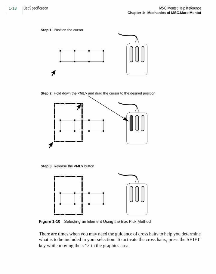
Suppose the number of subdivisions was set to 20 by 20, creating 400 elements. Assume you want to enter the left 200 elements in a list by creating a rectangle to fence in those elements. Position the at one of the corners of the box. Depress the <ML> and move the to the opposite corner of the box you want to create. The rectangle that appears tells you exactly which elements are included in the box. Once you have reached the desired position, release <ML>. Every element that is completely inside the box is included in the list specification.
< >
< >
< >
< >
List Specification MSC.Mentat Help ReferenceChapter 1: Mechanics of MSC.Marc Mentat
1-18
Figure 1-10 Selecting an Element Using the Box Pick Method
There are times when you may need the guidance of cross hairs to help you determine what is to be included in your selection. To activate the cross hairs, press the SHIFT key while moving the in the graphics area.
Step 1: Position the cursor
Step 2: Hold down the <ML> and drag the cursor to the desired position
Step 3: Release the <ML> button
< >
1-19MSC.Mentat Help Reference List SpecificationChapter 1: Mechanics of MSC.Marc Mentat
Note: You can relax the completely inside constraint mentioned previously by using the PARTIAL button on the picking panel under DEVICE.
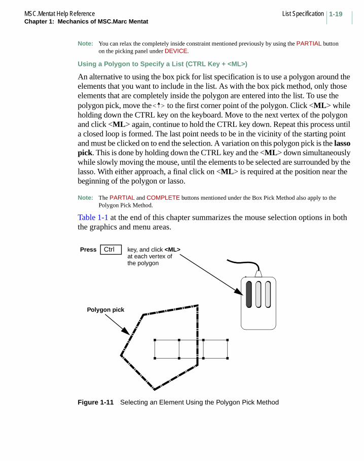
Using a Polygon to Specify a List (CTRL Key + <ML>)
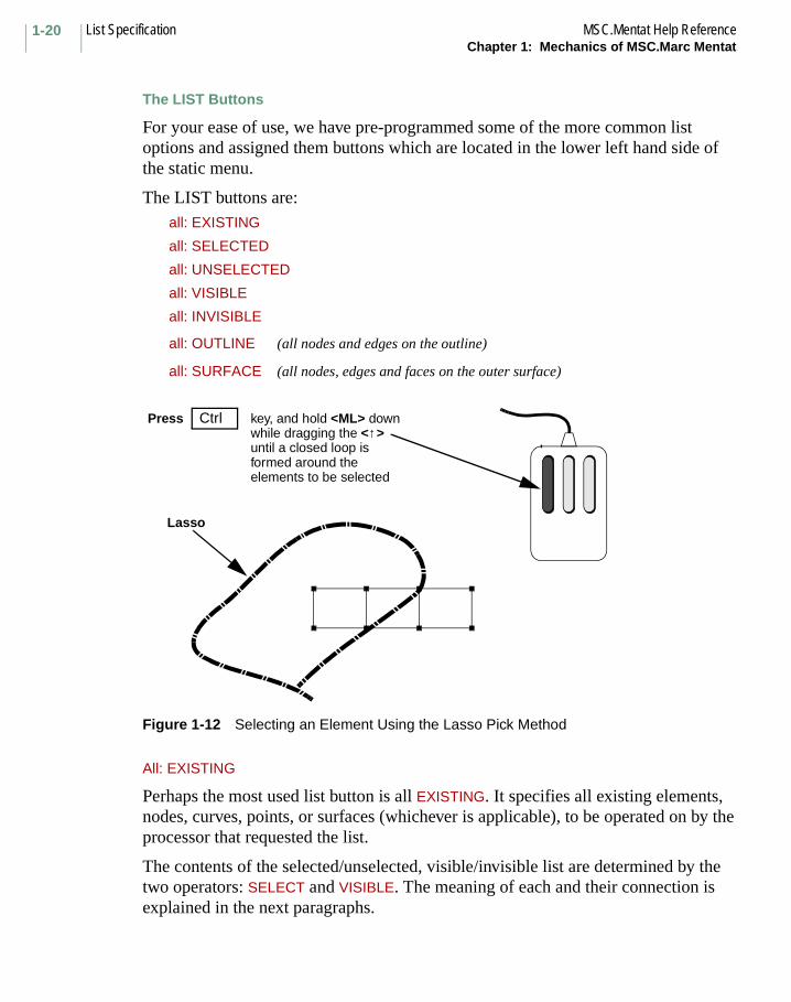
An alternative to using the box pick for list specification is to use a polygon around the elements that you want to include in the list. As with the box pick method, only those elements that are completely inside the polygon are entered into the list. To use the polygon pick, move the to the first corner point of the polygon. Click <ML> while holding down the CTRL key on the keyboard. Move to the next vertex of the polygon and click <ML> again, continue to hold the CTRL key down. Repeat this process until a closed loop is formed. The last point needs to be in the vicinity of the starting point and must be clicked on to end the selection. A variation on this polygon pick is the lasso pick. This is done by holding down the CTRL key and the <ML> down simultaneously while slowly moving the mouse, until the elements to be selected are surrounded by the lasso. With either approach, a final click on <ML> is required at the position near the beginning of the polygon or lasso.
Note: The PARTIAL and COMPLETE buttons mentioned under the Box Pick Method also apply to the Polygon Pick Method.
Table 1-1 at the end of this chapter summarizes the mouse selection options in both the graphics and menu areas.
Figure 1-11 Selecting an Element Using the Polygon Pick Method
< >
Press Ctrl key, and click <ML>at each vertex ofthe polygon
Polygon pick
List Specification MSC.Mentat Help ReferenceChapter 1: Mechanics of MSC.Marc Mentat
1-20
The LIST Buttons
For your ease of use, we have pre-programmed some of the more common list options and assigned them buttons which are located in the lower left hand side of the static menu.
The LIST buttons are:all: EXISTING
all: SELECTED
all: UNSELECTED
all: VISIBLE
all: INVISIBLE
all: OUTLINE (all nodes and edges on the outline)
all: SURFACE (all nodes, edges and faces on the outer surface)
Figure 1-12 Selecting an Element Using the Lasso Pick Method
All: EXISTING
Perhaps the most used list button is all EXISTING. It specifies all existing elements, nodes, curves, points, or surfaces (whichever is applicable), to be operated on by the processor that requested the list.
The contents of the selected/unselected, visible/invisible list are determined by the two operators: SELECT and VISIBLE. The meaning of each and their connection is explained in the next paragraphs.
Press Ctrl key, and hold <ML> downwhile dragging the <↑>until a closed loop is
Lasso
formed around the elements to be selected

1-21MSC.Mentat Help Reference List SpecificationChapter 1: Mechanics of MSC.Marc Mentat
All: SELECTED/UNSELECTED
The SELECT operator is a very powerful way to separate specific items from others. The methods by which items are selected range from a single item to a path of nodes, a box of items, or all items on a plane, and are connected by Boolean operators such as and, except, invert, and intersect. An example of this syntax is:
(use) single [items] and (a) box (of) [items] except single [items]
where the words use, a, of, and item are implied because they do not appear as buttons. A powerful feature of the SELECT processor is the ability to name a group of items, and refer to them by that name in list specifications. The STORE command facilitates this process.
Figure 1-13 Location of LIST Buttons
All: VISIBLE/INVISIBLE
Sometimes the model may be so complex that it takes an unacceptably long time to update the graphics screen every time the database changes. It is advantageous to focus on the items that you are working on. By activating and deactivating items from the display list, you can minimize the items that are displayed. Note that activating or deactivating does not imply that they are removed from the database. The PLOT processor facilitates this activation and deactivation process by using the VISIBLE and INVISIBLE commands.
GraphicsDynamicMenu
Static Menu
Dialogue Status
xxxxxxxxxxxxxxxxxxxxxxxxxx
Location of most commonLIST buttons in STATIC Menu Area
x
y
List Specification MSC.Mentat Help ReferenceChapter 1: Mechanics of MSC.Marc Mentat
1-22
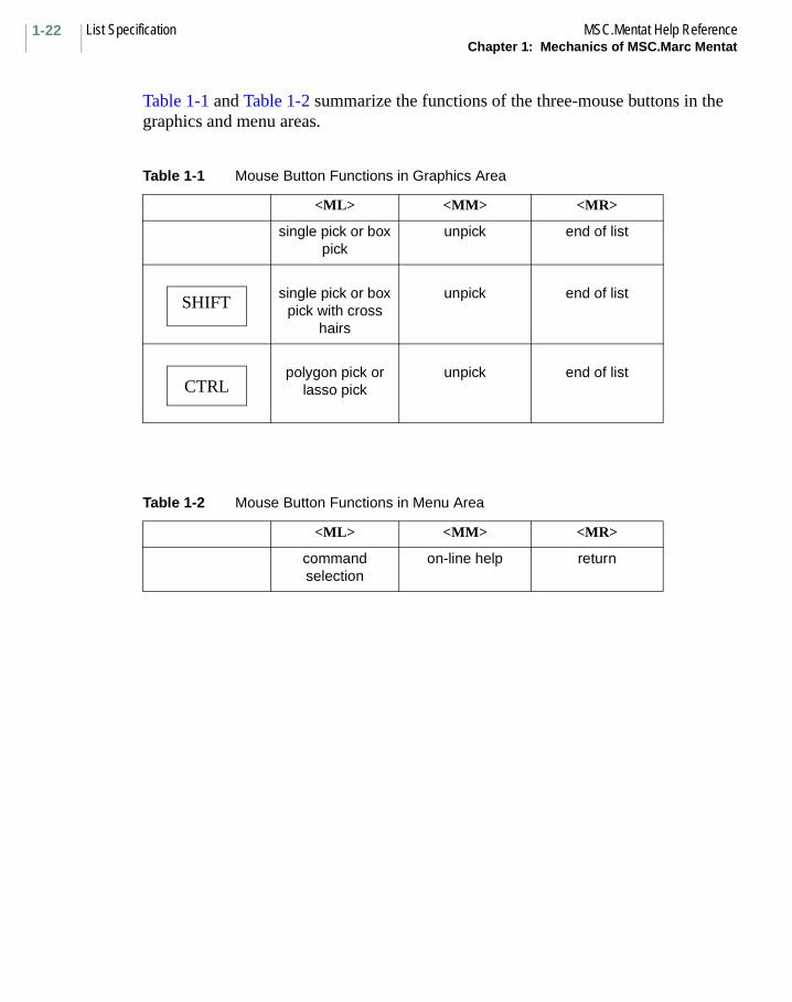
Table 1-1 and Table 1-2 summarize the functions of the three-mouse buttons in the graphics and menu areas.
Table 1-1 Mouse Button Functions in Graphics Area
<ML> <MM> <MR>
single pick or box pick
unpick end of list
single pick or box pick with cross
hairs
unpick end of list
polygon pick or lasso pick
unpick end of list
Table 1-2 Mouse Button Functions in Menu Area
<ML> <MM> <MR>
command selection
on-line help return
SHIFT
CTRL
1-23MSC.Mentat Help Reference IdentifiersChapter 1: Mechanics of MSC.Marc Mentat
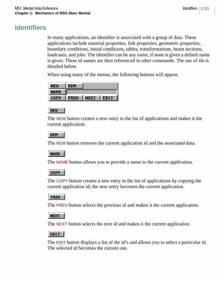
IdentifiersIn many applications, an identifier is associated with a group of data. These applications include material properties, link properties, geometric properties, boundary conditions, initial conditions, tables, transformations, beam sections, loadcases, and jobs. The identifier can be any name, if none is given a default name is given. These id names are then referenced in other commands. The use of ids is detailed below.
When using many of the menus, the following buttons will appear.
The NEW button creates a new entry in the list of applications and makes it the current application.
The REM button removes the current application id and the associated data.
The NAME button allows you to provide a name to the current application.
The COPY button creates a new entry in the list of applications by copying the current application id; the new entry becomes the current application.
The PREV button selects the previous id and makes it the current application.
The NEXT button selects the next id and makes it the current application.
The EDIT button displays a list of the id’s and allows you to select a particular id. The selected id becomes the current one.

Identifiers MSC.Mentat Help ReferenceChapter 1: Mechanics of MSC.Marc Mentat
1-24

Chapter 2: Main Menu
CHAPTER
2 Main Menu
■ Main Menu Overview
■ Preprocessing Menus
■ Analysis Menus
■ Postprocessing Menus
■ Configuration Menus
■ Quit Command
■ Static Menus
■ Utilities Menus
■ Files Menu
■ Plot Menu
■ View Menu
■ Static Commands, Continued
■ List Commands

Main Menu Overview MSC.Marc Mentat Help ReferenceChapter 2: Main Menu
2-2
Main Menu OverviewTo begin a Mentat session, move to the directory into which you would like your files to be saved, or in which previous files exist, and type mentat. The directory to which you have moved “cd” or “setdir” is your working directory.
The main menu is displayed on the screen. This menu consists of preprocessing, analysis, postprocessing, and configuration menus along the left of the screen, and the universal command menus along the bottom.
Figure 2-1 Main Menu

2-3MSC.Marc Mentat Help Reference Preprocessing MenusChapter 2: Main Menu
Preprocessing Menus
This menu contains commands that are used to create and/or edit geometry and the finite element mesh. Functionality includes adding, removing, and editing nodes, elements, points, curves, surfaces, and solids of new or existing meshes. In addition to these basic functions, the MESH GENERATION menu contains several submenus with commands for transforming the finite element mesh or the geometry.
This menu contains commands that apply boundary conditions to the finite element mesh or the underlying geometry. The types of boundary conditions that can be applied depend upon the type of analysis being performed. Examples of boundary conditions include:
• fixed displacements • loads• pressures • temperatures• heat fluxes • velocities• voltages • currents• potentials • charges
This menu contains commands that are used to define the initial conditions. The type of initial conditions that can be applied depend upon the type of analysis being performed. Example of initial conditions include:
• Initial Velocity • Initial State Variables• Initial Stress • Initial Temperatures• Initial Void Ratio
This menu contains commands for defining links or multi-point constraints (MPCs). The types of links that can be created are nodal ties, servo links, and springs/dashpots.

Preprocessing Menus MSC.Marc Mentat Help ReferenceChapter 2: Main Menu
2-4
This menu contains commands that specify material properties to be used in the analysis. Material properties may be specified for the following analysis types:
• mechanical • bearing• heat transfer • electrostatic• joule heating • magnetostatic• acoustic • electromagnetic
Typical material properties include: Young’s modulus, Poisson’s ratio, mass density, conductivity, specific heat, viscosity, and resistivity.
Default material properties are used if they are not specified. It is required that all the elements are assigned some material properties for a proper analysis.
This menu contains commands for defining sets of geometric properties and applying them to elements in the model. The types of properties that can be defined include truss area, beam properties, and plate/shell thickness. Additionally, element behavior such as constant dilatation and assumed strain formulation may be activated.
This menu contains commands for defining contact bodies in a contact analysis. The contact bodies can be classified as either rigid or deformable.
This menu contains commands for defining the a fracture mechanics application which use the J-intregral for investigating cracks in a structure.
This menu contains commands for defining the remeshing characteristics to be used when remeshing is performed in the analysis.

2-5MSC.Marc Mentat Help Reference Analysis MenusChapter 2: Main Menu
With this menu, the user enters the area where the design variables and design constraints can be specified for a design optimization or design sensitivity analysis job.
Design optimization refers to the process by which certain parameters (design variables) of a finite element model are modified in order to reach a feasible and desirable (improved) design. Design sensitivity, in the context of Marc, refers to the process whereby first-order derivatives of response quantities with respect to each of the design variables are computed and output. Element contributions to each response quantity are also computed and are made available.
Analysis Menus
This menu contains commands that specify the parameters needed to perform one or more increments of analysis using the Marc program. The operations that may be performed include load selection, specification of load distribution defining the time step and specifying the convergence requirements. It is not required to set up the loadcase for a simple linear analysis.
The main objective of the menu is to combine individual boundary conditions into a loadcase.
This menu contains commands that define, run, and monitor the analysis. Multiple loadcases may be assembled into one analysis job. The output is controlled and analysis parameters are defined.
Postprocessing Menus MSC.Marc Mentat Help ReferenceChapter 2: Main Menu
2-6
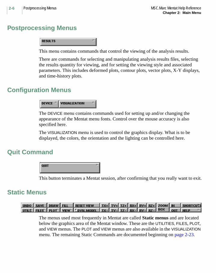
Postprocessing Menus
This menu contains commands that control the viewing of the analysis results.
There are commands for selecting and manipulating analysis results files, selecting the results quantity for viewing, and for setting the viewing style and associated parameters. This includes deformed plots, contour plots, vector plots, X-Y displays, and time-history plots.
Configuration Menus
The DEVICE menu contains commands used for setting up and/or changing the appearance of the Mentat menu fonts. Control over the mouse accuracy is also specified here.
The VISUALIZATION menu is used to control the graphics display. What is to be displayed, the colors, the orientation and the lighting can be controlled here.
Quit Command
This button terminates a Mentat session, after confirming that you really want to exit.
Static Menus
The menus used most frequently in Mentat are called Static menus and are located below the graphics area of the Mentat window. These are the UTILITIES, FILES, PLOT, and VIEW menus. The PLOT and VIEW menus are also available in the VISUALIZATION menu. The remaining Static Commands are documented beginning on page 2-23.

2-7MSC.Marc Mentat Help Reference Utilities MenusChapter 2: Main Menu
Utilities MenusThe first of the Static menus is the UTILITIES menu. It contains commands which allow you to print the screen image, create or execute a procedure file, create command aliases, define parameters, determine the size of the database, annotate the display, and obtain geometric and coordinate data.
Figure 2-2 Utilities Menu, Part I
When the MORE button is selected, the remainder of the UTILITIES menu is displayed.
Utilities Menus MSC.Marc Mentat Help ReferenceChapter 2: Main Menu
2-8
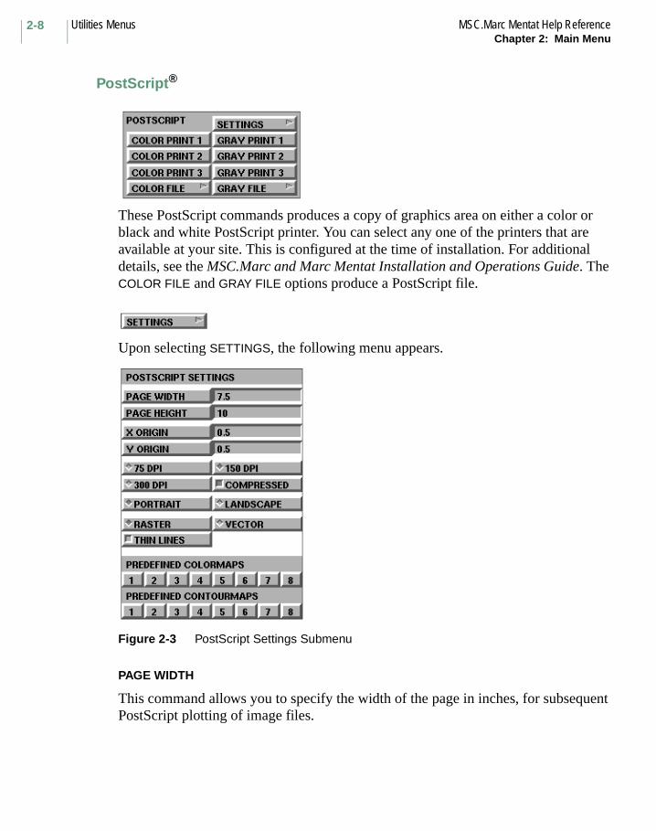
PostScript®
These PostScript commands produces a copy of graphics area on either a color or black and white PostScript printer. You can select any one of the printers that are available at your site. This is configured at the time of installation. For additional details, see the MSC.Marc and Marc Mentat Installation and Operations Guide. The COLOR FILE and GRAY FILE options produce a PostScript file.
Upon selecting SETTINGS, the following menu appears.
Figure 2-3 PostScript Settings Submenu
PAGE WIDTH
This command allows you to specify the width of the page in inches, for subsequent PostScript plotting of image files.

2-9MSC.Marc Mentat Help Reference Utilities MenusChapter 2: Main Menu
PAGE WIDTH
This command allows you to specify the height of the page in inches, for subsequent PostScript plotting of image files.
X ORIGIN
This command allows you to specify the X origin of the image in inches, for subsequent PostScript plotting of image files.
Y ORIGIN
This command allows you to specify the Y origin of the image in inches, for subsequent PostScript plotting of image files.
76 DPI, 150 DPI, and 300 DPI
These commands allows you to specify the resolution of the image to be printed.
COMPRESSED
Normally, compression is used to minimize the size of file when printing. Some systems do not support this, in which case it should be disabled.
PORTRAIT
This command aligns the image with the page in subsequent PostScript files (no rotation of the image). Thus, the current page width is used for the image’s width.
LANDSCAPE
This command rotates the image 90 degrees in subsequent PostScript files. Thus, the current page height is used for the image’s width, and this often results in a larger printed image. This will be the effect when the graphics window width is greater than its height, and when the current page height is greater than its width.
RASTER
This command selects the method of producing PostScript files. By default, it draws the Mentat geometry to a virtual graphics window of arbitrary size (resolution). With this method the final PostScript file contains a raster representation of the drawn image.
VECTOR
This command selects the method of producing PostScript files. It simply writes raw geometric primitives such as lines and text to the output file.
Utilities Menus MSC.Marc Mentat Help ReferenceChapter 2: Main Menu
2-10
THIN LINES
This command turns the thin line option for raster PostScript output ON or OFF. This feature (which is off by default) makes all the drawn lines have a width of one dot or pixel. This can be desirable for high resolution images that have many lines (such as a mesh with many thousands of elements). When this option is off, a thicker line width is used, which compensates for varying resolutions.
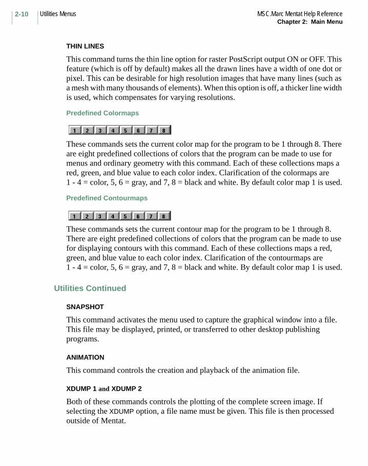
Predefined Colormaps
These commands sets the current color map for the program to be 1 through 8. There are eight predefined collections of colors that the program can be made to use for menus and ordinary geometry with this command. Each of these collections maps a red, green, and blue value to each color index. Clarification of the colormaps are 1 - 4 = color, 5, 6 = gray, and 7, 8 = black and white. By default color map 1 is used.
Predefined Contourmaps
These commands sets the current contour map for the program to be 1 through 8. There are eight predefined collections of colors that the program can be made to use for displaying contours with this command. Each of these collections maps a red, green, and blue value to each color index. Clarification of the contourmaps are 1 - 4 = color, 5, 6 = gray, and 7, 8 = black and white. By default color map 1 is used.
Utilities Continued
SNAPSHOT
This command activates the menu used to capture the graphical window into a file. This file may be displayed, printed, or transferred to other desktop publishing programs.
ANIMATION
This command controls the creation and playback of the animation file.
XDUMP 1 and XDUMP 2
Both of these commands controls the plotting of the complete screen image. If selecting the XDUMP option, a file name must be given. This file is then processed outside of Mentat.

2-11MSC.Marc Mentat Help Reference Utilities MenusChapter 2: Main Menu
FULL WINDOW
This command controls the creation and playback of the animation file.
PARAMETERS
These commands define parameters. These parameters may be used at any point in the session, or in a procedure file.
ALIASES
These commands control defining aliasing of commands.
PROCEDURES
This command allows you to save commands into a file, or to replay a file containing previously created commands.
PYTHON
These menus allow you to select a Python script to run and whether the script is to be run as a separate process which allows the graphics to be updated as the script proceeds. It also allows for the initialization of a connection so that a Python script may be started in an external window.
CURRENT DIRECTORY
This command lists the files in a directory. To obtain files in the current directory, type “.”
EDIT FILE
This command edits a file with the editor.
LIST DIRECTORY
This command allows you to enter a directory path.
SYSTEM COMMAND
This command enters one system command at a time.
SYSTEM SHELL
This command changes the modes between C-shell and Bourne shell.
Utilities Menus MSC.Marc Mentat Help ReferenceChapter 2: Main Menu
2-12
DISTANCE
This command calculates the distance between two points, and the angles from the global axes.
CALCULATE
This command calculates the value of an expression.
SIZES
This command brings up the submenu that reports on the size of the database, the number of nodes, elements, points, curves, surfaces, and solids in the geometry, the number of material and boundary condition ids, etc.
SAMPLE ELEMENT
This command returns the selected element number and the coordinates of an arbitrary point.
RESET PROGRAM
This command resets the program flags to their default values. This does not modify the database nor does it reset the view menu commands. To initialize the database, use the NEW command in the FILES menu.
UNDO
This command sets the undo capability on or off. If set to off, you cannot undo a command. The program will not backup the database in this mode.
GENERALIZED XY PLOT
This command has the ability to collect plots from various plotters: History plot, Response Gradient/Design Variable plot, Path plot, Tables and Data Fit plot. The overlapping feature allows the user to compare plots.
Utilities, More Menu
Annotations
The following commands are used to add annotations to the graphical display. Annotations can currently be added to the display of the model. They cannot be added to path or history plots. Annotations are tied to a view and will not appear in all views.
2-13MSC.Marc Mentat Help Reference Utilities MenusChapter 2: Main Menu
DISPLAY ANNOTATIONS
This command sets the annotations on or off.
ADD
This command adds an annotation; type in the annotation and give the location.
REMOVE
This command removes an annotation. Select the annotation to be removed.
SHOW
This command lists all active annotations.
EDIT
This command edits an existing annotation. Select the annotation to be edited.
MOVE
This command redefines the location of the annotation. Select the annotation, and give the new location.
COPY
This command copies an annotation to a new location. Select the annotation, and give the location.
CLEAR
This command removes all annotations.
Length, Area, & Volume Calculations
Direct Methods
EDGE LENGTH
This command determines the total length of a list of element edges.
FACE AREA
This command determines the total area of a list of element faces.
ELEMENT VOLUME
This command determines the total volume of a list of solid elements.

Utilities Menus MSC.Marc Mentat Help ReferenceChapter 2: Main Menu
2-14
ELEMENT MASS
This command determines the mass of an element.
SOLID AREA
This command determines the solid surface area of element.
SOLID VOLUME
This command determines the solid volume of an element.
Enclosing Methods
EDGE AREA
This command calculates the area enclosed by a list of edges.
FACE VOLUME
This command calculates the volume enclosed by a list of faces.
2-15MSC.Marc Mentat Help Reference Files MenuChapter 2: Main Menu
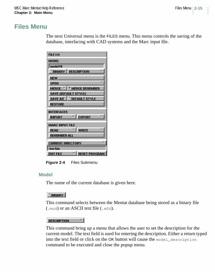
Files MenuThe next Universal menu is the FILES menu. This menu controls the saving of the database, interfacing with CAD systems and the Marc input file.
Figure 2-4 Files Submenu
Model
The name of the current database is given here.
This command selects between the Mentat database being stored as a binary file (.mud) or an ASCII text file (.mfd).
This command bring up a menu that allows the user to set the description for the current model. The text field is used for entering the description. Either a return typed into the text field or click on the OK button will cause the model_description command to be executed and close the popup menu.

Files Menu MSC.Marc Mentat Help ReferenceChapter 2: Main Menu
2-16
This command removes all contents of the in-core memory data structure, and initialize all counters to zero.
This command opens an existing database and reads it into memory.
This command opens an existing database and merges the contents with the current database. The elements, nodes, etc. will be renumbered and be given the higher numbers. To eliminate nodes and points at identical positions, use the SWEEP option in the MESH GENERATION menu.
This command controls the renumbering of model entities during a model merge operation. When a model is renumbered, all entities will be assigned new ids based upon their creation order. A merged model will receive higher ids than the existing model.
This command saves the existing database to a file.
This command saves the existing database to a new file. The new name becomes the current name of this session.
This command specifies the format of the model file. It only affects the save_as_model (SAVE AS) command. The formats are: 2001 Style, 2000 Style, 3.3 Style, 3.2 Style, 3.1 Style, and 2.3.1 Style.
This command restores the last written database into memory.
2-17MSC.Marc Mentat Help Reference Files MenuChapter 2: Main Menu
Interfaces
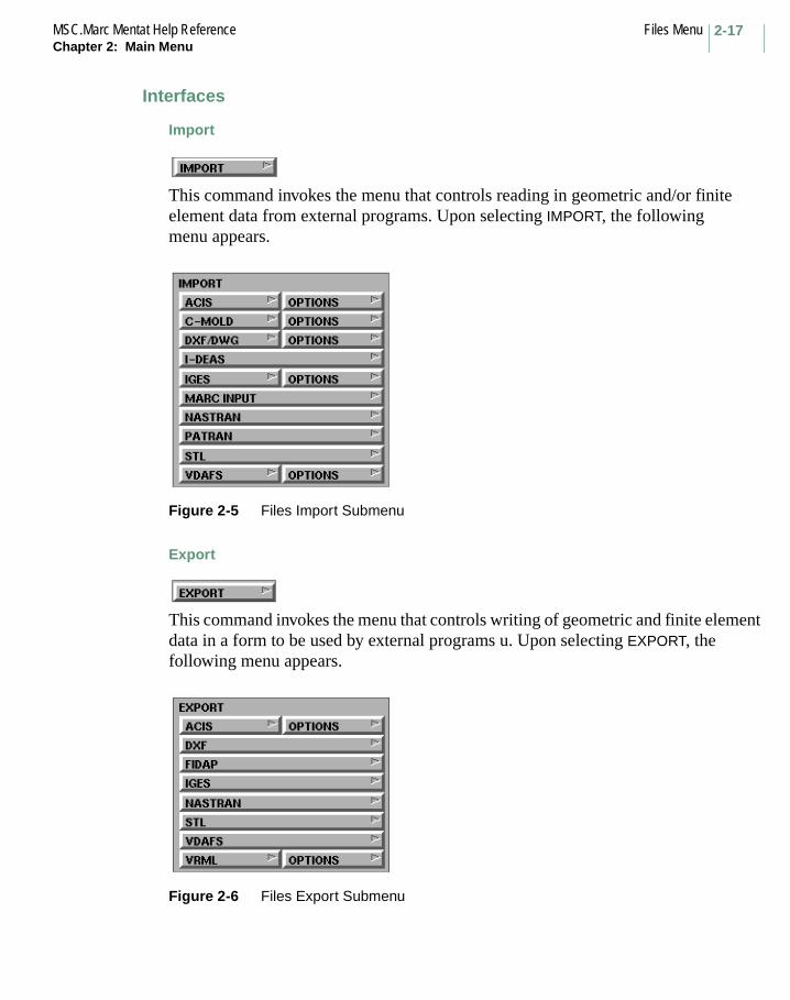
Import
This command invokes the menu that controls reading in geometric and/or finite element data from external programs. Upon selecting IMPORT, the following menu appears.
Figure 2-5 Files Import Submenu
Export
This command invokes the menu that controls writing of geometric and finite element data in a form to be used by external programs u. Upon selecting EXPORT, the following menu appears.
Figure 2-6 Files Export Submenu
Files Menu MSC.Marc Mentat Help ReferenceChapter 2: Main Menu
2-18
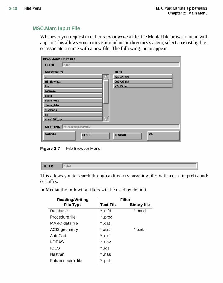
MSC.Marc Input File
Whenever you request to either read or write a file, the Mentat file browser menu will appear. This allows you to move around in the directory system, select an existing file, or associate a name with a new file. The following menu appear.
Figure 2-7 File Browser Menu
This allows you to search through a directory targeting files with a certain prefix and/or suffix.
In Mentat the following filters will be used by default.
Reading/WritingFile Type
FilterText File Binary file
Database * .mfd * .mud
Procedure file * .proc
MARC data file * .dat
ACIS geometry * .sat * .sab
AutoCad * .dxf
I-DEAS * .unv
IGES * .igs
Nastran * .nas
Patran neutral file * .pat
2-19MSC.Marc Mentat Help Reference Files MenuChapter 2: Main Menu
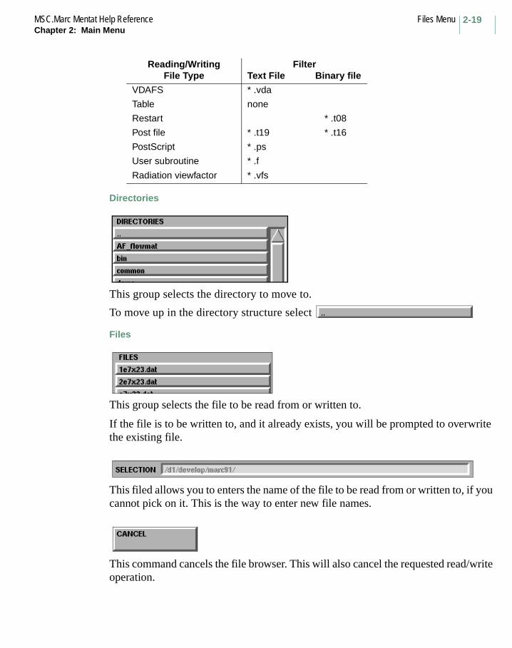
Directories
This group selects the directory to move to.
To move up in the directory structure select
Files
This group selects the file to be read from or written to.
If the file is to be written to, and it already exists, you will be prompted to overwrite the existing file.
This filed allows you to enters the name of the file to be read from or written to, if you cannot pick on it. This is the way to enter new file names.
This command cancels the file browser. This will also cancel the requested read/write operation.
VDAFS * .vda
Table none
Restart * .t08
Post file * .t19 * .t16
PostScript * .ps
User subroutine * .f
Radiation viewfactor * .vfs
Reading/WritingFile Type
FilterText File Binary file

Files Menu MSC.Marc Mentat Help ReferenceChapter 2: Main Menu
2-20
This command resets the file browser to the users working directory.
This command rescans the current file system to update the list of files with those files created or removed since the last time this directory was read.
This command accepts the name of the file given in the SELECTION area, and proceed to do the requested I/O operation.
This command renumbers all entities in the model (nodes, elements, etc.) starting at the start id (default 1), and incrementing by the specified increment (default 1).
This command allows you to change the program’s current directory. The current directory is initially the directory from which Mentat was started. Relative path and file names specified to Mentat begin at the current directory.
This command opens a window with a text editor which enables you to edit a given file.
This command resets all program controls except viewing to the default values. The contents of the database are not changed. To remove the contents of the database, use the NEW command.

2-21MSC.Marc Mentat Help Reference Plot MenuChapter 2: Main Menu
Plot MenuThe PLOT menu controls the style of the plot geometry. It is typically used to control what type of geometric entities are to be displayed, labelled, whether they are in wireframe or filled mode.
Figure 2-8 Plot Menus
View Menu MSC.Marc Mentat Help ReferenceChapter 2: Main Menu
2-22
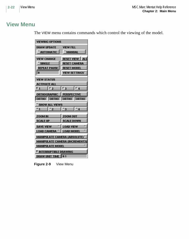
View MenuThe VIEW menu contains commands which control the viewing of the model.
Figure 2-9 View Menu
2-23MSC.Marc Mentat Help Reference Static Commands, ContinuedChapter 2: Main Menu
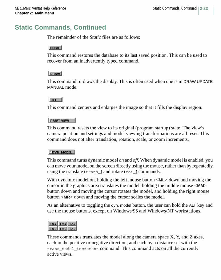
Static Commands, ContinuedThe remainder of the Static files are as follows:
This command restores the database to its last saved position. This can be used to recover from an inadvertently typed command.
This command re-draws the display. This is often used when one is in DRAW UPDATE MANUAL mode.
This command centers and enlarges the image so that it fills the display region.
This command resets the view to its original (program startup) state. The view’s camera position and settings and model viewing transformations are all reset. This command does not alter translation, rotation, scale, or zoom increments.
This command turns dynamic model on and off. When dynamic model is enabled, you can move your model on the screen directly using the mouse, rather than by repeatedly using the translate (trans_) and rotate (rot_) commands.
With dynamic model on, holding the left mouse button <ML> down and moving the cursor in the graphics area translates the model, holding the middle mouse <MM> button down and moving the cursor rotates the model, and holding the right mouse button <MR> down and moving the cursor scales the model.
As an alternative to toggling the dyn. model button, the user can hold the ALT key and use the mouse buttons, except on Windows/95 and Windows/NT workstations.
These commands translates the model along the camera space X, Y, and Z axes, each in the positive or negative direction, and each by a distance set with the trans_model_increment command. This command acts on all the currently active views.
Static Commands, Continued MSC.Marc Mentat Help ReferenceChapter 2: Main Menu
2-24
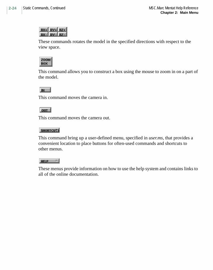
These commands rotates the model in the specified directions with respect to the view space.
This command allows you to construct a box using the mouse to zoom in on a part of the model.
This command moves the camera in.
This command moves the camera out.
This command bring up a user-defined menu, specified in user.ms, that provides a convenient location to place buttons for often-used commands and shortcuts to other menus.
These menus provide information on how to use the help system and contains links to all of the online documentation.

2-25MSC.Marc Mentat Help Reference List CommandsChapter 2: Main Menu
List CommandsThe following common commands do not appear in the MAIN menu, but appear in nearly all other Mentat menus. Since they are globally located, they are documented in this chapter alone for clarity.
These pseudo-commands, which are always available regardless of which Mentat menu you are using, are shortcuts for providing entity lists to the command line. They may be used whenever a command expects a list of entities. Each pseudo-command generates a list of entities of the requested type and sends the list to the command requesting the list. The types of lists generated are as follows:
This command lists all entities of the requested type.
This command lists all entities of the requested type that are currently selected.
This command lists all entities of the requested type that are not currently selected.
This command lists all entities of the requested type that are visible.
This command lists all entities of the requested type that are invisible.
This command lists all entities of the requested type on the outline of the model.
This command lists all entities of the requested type on the surface of the model.

List Commands MSC.Marc Mentat Help ReferenceChapter 2: Main Menu
2-26
Select Processor
The SELECT menu is used to manage lists of entities. A variety of filters, methods, and modes are available which provide convenient means for the generation of the lists.
The SELECT commands are used to place entities into a selected state and are used in conjunction with the ALL SELECTED and ALL UNSELECTED list macros to generate input to commands requiring a list of entities.
The SELECT processor may also be used to control the visibility of entities.
This command lists the currently defined sets.
This command terminates the current list of entries being entered by sending a pound sign (#) to the command line. When entering a list of items with the mouse, clicking on the left button while the mouse is in the graphics area has the same effect.

Mentat Help Commands in AACTIVATE ALL
Command: activate_all_views
Description: This command (along with activate_view and deactivate_view) is used for multiple view management. Only active views are affected by view setting commands. The visibility of views is controlled by show_view and the show_all_views commands. Views may be visible but not active and vice versa. When the program is started, view 1 is the only active and visible view.
This command will activate all views.
When a view is made visible, it is automatically activated. When a view is made invisible, it is automatically deactivated. The three commands activate_all_views, activate_view, and deactivate_view allow you to override this.
Also see: activate_view, deactivate_view, and show_view.
Keyboard Command Sequence:
activate_all_views
A Commands Begin with A
ACTIVATE ALL

Mentat Help Commands in A MSC.Mentat Help ReferenceA-2
1
Command: activate_viewdeactivate_view
Description: These commands are used for multiple view management. Only active views are affected by view setting commands. The visibility of views is controlled by show_view and the show_all_views commands. Views may be visible but not active and vice versa. When the program is started, view 1 is the only active and visible view.
You must specify the view to be operated on. Views are specified by number, 1-4.
When a view is made visible, it is automatically activated, and when a view is made invisible, it is automatically deactivated. The three commands activate_all_views, activate_view, and deactivate_view allow you to override this.
Also see activate_all_views and show_view.
Keyboard Command Sequence:
activate_view <view number>deactivate_view <view number>
Other Buttons with the same description:
234
NAME
Command: adapg_name
Description: This command sets or changes the name of the current entry in the list of remeshing criteria.
Keyboard Command Sequence:
adapg_name <adapg name>
1
NAME
A-3MSC.Mentat Help Reference Mentat Help Commands in A
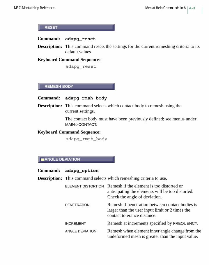
RESET
Command: adapg_reset
Description: This command resets the settings for the current remeshing criteria to its default values.
Keyboard Command Sequence: adapg_reset
REMESH BODY
Command: adapg_rmsh_body
Description: This command selects which contact body to remesh using the current settings.
The contact body must have been previously defined; see menus under MAIN->CONTACT.
Keyboard Command Sequence: adapg_rmsh_body
ANGLE DEVIATION
Command: adapg_option
Description: This command selects which remeshing criteria to use.
ELEMENT DISTORTION Remesh if the element is too distorted or anticipating the elements will be too distorted. Check the angle of deviation.
PENETRATION Remesh if penetration between contact bodies is larger than the user input limit or 2 times the contact tolerance distance.
INCREMENT Remesh at increments specified by FREQUENCY.
ANGLE DEVIATION Remesh when element inner angle change from the undeformed mesh is greater than the input value.
RESET
REMESH BODY
ANGLE DEVIATION
Mentat Help Commands in A MSC.Mentat Help ReferenceA-4
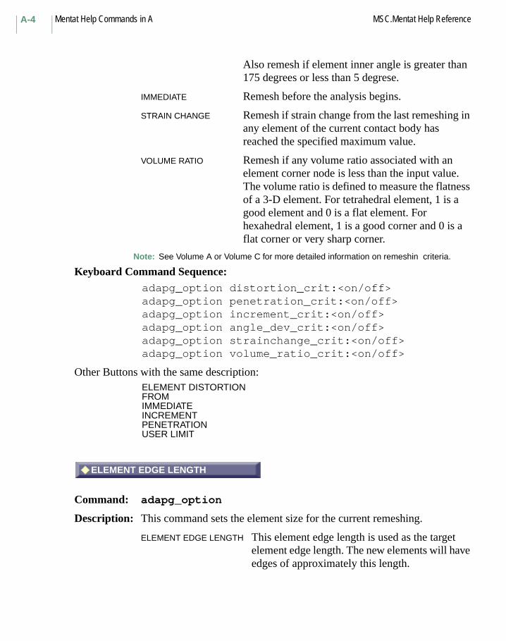
Also remesh if element inner angle is greater than 175 degrees or less than 5 degrese.
IMMEDIATE Remesh before the analysis begins.
STRAIN CHANGE Remesh if strain change from the last remeshing in any element of the current contact body has reached the specified maximum value.
VOLUME RATIO Remesh if any volume ratio associated with an element corner node is less than the input value. The volume ratio is defined to measure the flatness of a 3-D element. For tetrahedral element, 1 is a good element and 0 is a flat element. For hexahedral element, 1 is a good corner and 0 is a flat corner or very sharp corner.
Note: See Volume A or Volume C for more detailed information on remeshin criteria.
Keyboard Command Sequence: adapg_option distortion_crit:<on/off>adapg_option penetration_crit:<on/off>adapg_option increment_crit:<on/off>adapg_option angle_dev_crit:<on/off>adapg_option strainchange_crit:<on/off>adapg_option volume_ratio_crit:<on/off>
Other Buttons with the same description:ELEMENT DISTORTIONFROM IMMEDIATEINCREMENTPENETRATIONUSER LIMIT
ELEMENT EDGE LENGTH
Command: adapg_option
Description: This command sets the element size for the current remeshing.
ELEMENT EDGE LENGTH This element edge length is used as the target element edge length. The new elements will have edges of approximately this length.
ELEMENT EDGE LENGTH
A-5MSC.Mentat Help Reference Mentat Help Commands in A
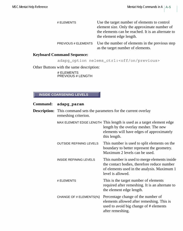
# ELEMENTS Use the target number of elements to control element size. Only the approximate number of the elements can be reached. It is an alternate to the element edge length.
PREVIOUS # ELEMENTS Use the number of elements in the previous step as the target number of elements.
Keyboard Command Sequence: adapg_option nelems_ctrl:<off/on/previous>
Other Buttons with the same description:# ELEMENTSPREVIOUS # LENGTH
INSIDE COARSENING LEVELS
Command: adapg_param
Description: This command sets the parameters for the current overlay remeshing criterion.
MAX ELEMENT EDGE LENGTH This length is used as a target element edge length by the overlay mesher. The new elements will have edges of approximately this length.
OUTSIDE REFINING LEVELS This number is used to split elements on the boundary to better represent the geometry. Maximum 2 levels can be used.
INSIDE REFINING LEVELS This number is used to merge elements inside the contact bodies, therefore reduce number of elements used in the analysis. Maximum 1 level is allowed.
# ELEMENTS This is the target number of elements required after remeshing. It is an alternate to the element edge length.
CHANGE OF # ELEMENTS(%) Percentage change of the number of elements allowed after remeshing. This is used to avoid big change of # elements after remeshing.
INSIDE COARSENING LEVELS

Mentat Help Commands in A MSC.Mentat Help ReferenceA-6
Keyboard Command Sequence: adapg_param max_edge_len <value>adapg_apram refine_levels <value>adapg_param coarsen_levels <value>adapg_param nelems <value>adapg_param dnelems_pct <value>
Another Button with the same description:OUTSIDE REFINING LEVELS
# ELEMENTS
Command: adapg_param
Description: This command sets the parameters for the current remeshing criterion.
ELEMENT EDGE LENGTH This length is used as a target element edge length by the overlay mesher. The new elements will have edges of approximately this length.
MIN. ELEMENT EDGE LENGTHMinimum element edge length is allowed in remeshing. By default, it is 1/3 of the target element edge length.
# ELEMENTS This is the target number of elements required after remeshing. It is an alternate to the element edge length.
CHANGE OF # ELEMENTS(%) Percentage change of the number of elements allowed after remeshing. This is used to avoid big change of # elements after remeshing.
CURVATURE CONTROL This is the number of divisions of a circle. Use this number to control refinement of outline with different curvatures.
SMOOTHING RATIO This ratio is used to control the outline smooth for remeshing. 0 means no smoothing and 1 means uniform.
FEATURE VERTEX ANGLE An angle between two edge vectors pointing outward of a point. Any point with the vertex angle smaller than this
# ELEMENTS
A-7MSC.Mentat Help Reference Mentat Help Commands in A
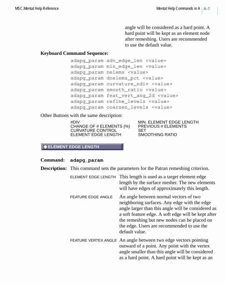
angle will be considered as a hard point. A hard point will be kept as an element node after remeshing. Users are recommended to use the default value.
Keyboard Command Sequence: adapg_param adv_edge_len <value>adapg_param min_edge_len <value>adapg_param nelems <value>adapg_param dnelems_pct <value>adapg_param curvature_ndiv <value>adapg_param smooth_ratio <value>adapg_param feat_vert_ang_2d <value>adapg_param refine_levels <value>adapg_param coarsen_levels <value>
Other Buttons with the same description:#DIV MIN. ELEMENT EDGE LENGTHCHANGE OF # ELEMENTS (%) PREVIOUS # ELEMENTSCURVATURE CONTROL SETELEMENT EDGE LENGTH SMOOTHING RATIO
ELEMENT EDGE LENGTH
Command: adapg_param
Description: This command sets the parameters for the Patran remeshing criterion.
ELEMENT EDGE LENGTH This length is used as a target element edge length by the surface mesher. The new elements will have edges of approximately this length.
FEATURE EDGE ANGLE An angle between normal vectors of two neighboring surfaces. Any edge with the edge angle larger than this angle will be considered as a soft feature edge. A soft edge will be kept after the remeshing but new nodes can be placed on the edge. Users are recommended to use the default value.
FEATURE VERTEX ANGLE An angle between two edge vectors pointing outward of a point. Any point with the vertex angle smaller than this angle will be considered as a hard point. A hard point will be kept as an
ELEMENT EDGE LENGTH

Mentat Help Commands in A MSC.Mentat Help ReferenceA-8
element node after remeshing. Users are recommended to use the default value.
COARSENING FACTOR This factor can be used to gradually enlarge the tetrahedral element size from the surface to the interior region during the remeshing. It will help reduce the total number of elements in the mesh. Users are recommended to use the default value.
MINIMUM EDGE LENGTH This element size is used in local refinement to control the smallest element size.
MAXIMUM EDGE LENGTH This element size is used in local refinement to control the largest element size.
CURVATURE CONTROL This parameter controls local refinement based on the curvature of the surfaces and curves. The number of divisions represents the division of a cycle.
CHANGE ELEMENT TYPE Patran Tetra mesher supports only Tetrahedral element type 157. If you need to convert element from Hex element you need to change the element type to 157 together with the IMMEDIATE command.
Keyboard Command Sequence: adapg_param del3_edge_len <value>adapg_param feat_edge_ang <value>adapg_param feat_vert_ang <value>adapg_param coarsen_factor <value>adapg_param pat3_min_edge_len <value>adapg_param pat3_max_edge_len <value>adapg_param pat3_curvature_ndiv <value>
Other buttons with the same description:SETMIN. ELEMENT EDGE LENGTH
A-9MSC.Mentat Help Reference Mentat Help Commands in A
ADVANCING FRONT QUAD
Command: adapg_type
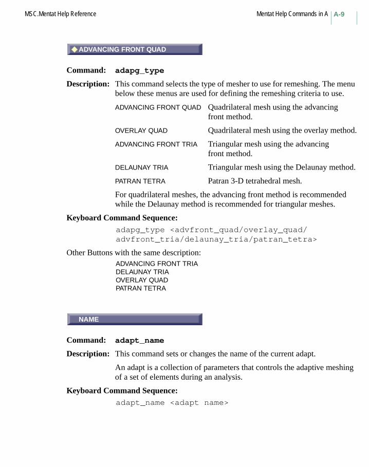
Description: This command selects the type of mesher to use for remeshing. The menu below these menus are used for defining the remeshing criteria to use.
ADVANCING FRONT QUAD Quadrilateral mesh using the advancing front method.
OVERLAY QUAD Quadrilateral mesh using the overlay method.
ADVANCING FRONT TRIA Triangular mesh using the advancing front method.
DELAUNAY TRIA Triangular mesh using the Delaunay method.
PATRAN TETRA Patran 3-D tetrahedral mesh.
For quadrilateral meshes, the advancing front method is recommended while the Delaunay method is recommended for triangular meshes.
Keyboard Command Sequence: adapg_type <advfront_quad/overlay_quad/advfront_tria/delaunay_tria/patran_tetra>
Other Buttons with the same description:ADVANCING FRONT TRIADELAUNAY TRIAOVERLAY QUADPATRAN TETRA
NAME
Command: adapt_name
Description: This command sets or changes the name of the current adapt.
An adapt is a collection of parameters that controls the adaptive meshing of a set of elements during an analysis.
Keyboard Command Sequence: adapt_name <adapt name>
ADVANCING FRONT QUAD
NAME

Mentat Help Commands in A MSC.Mentat Help ReferenceA-10
MAX # LEVELS
Command: adapt_param
Description: This command sets a parameter value for the current adaptivity criterion. You must specify the parameter name and its value. The applicable parameter that may be set depends on the type of the current adapt.
Keyboard Command Sequence: Adapt_param <Parameter Name> <Value>
Other Buttons with the same description:F2 through F5VALUEVALUE (ABS)VALUE (REL)XMAXXMINYMAXYMINZMAXZMIN
XMIN
Command: adapt_param xmin|ymin|zmin|xmax/|ymax|zmax
Description: This command defines the box for the NODE WITHIN BOX criterion. The box is defined in global X, Y, and Z as:
XMIN, YMIN, ZMIN to XMAX, YMAX, ZMAX.
Keyboard Command Sequence:
adapt_param <xmin|ymin|zmin|xmax/|ymax|zmax> <value>
Other Buttons with the same description:YMINZMINXMAXYMAXXMAX
MAX # LEVELS
XMIN

A-11MSC.Mentat Help Reference Mentat Help Commands in A
MAX # LEVELS
Command: adapt_param levels
Description: This command sets the number of levels an element is allowed to be subdivided. If set to zero the elements will not be subdivided.
Keyboard Command Sequence: adapt_param <param_levels>
VALUE (REL)
Command: adapt_param
Description: These commands set the parameter values for the uadap criterion.
VALUE (REL) an element is subdivided or unrefined if USER/max(USER) > REL where USER is defined in the user subroutine and max(USER) is the largest value for any element.
VALUE (ABS) an element is subdivided or unrefined if USER > ABS.
Keyboard Command Sequence: adapt_param value <param_value>adapt_param val_abs <param_value>
Other Buttons with the same description:VALUE (ABS)
UNREFINE
Command: adapt_option unrefine:<on|off>
Description: When this option is activated, elements are unrefined when all nodes of an element leaves the box.
Keyboard Command Sequence:
adapt_option unrefine:<on|off>
MAX # LEVELS
VALUE (REL)
UNREFINE

Mentat Help Commands in A MSC.Mentat Help ReferenceA-12
VALUE
Command: adapt_param value
Description: This command set the value for the TEMPERATURE GRADIENT criterion. The value must be less than 1.
Keyboard Command Sequence: adapt_param value <temperature>
RESET
Command: adapt_reset
Description: This command resets all values for the current adaptivity criterion.
Keyboard Command Sequence: adapt_reset
NODE WITHIN BOX
Command: adapt_type box
Description: This command sets the criterion type to NODE WITHIN BOX.
The user specifies a box, which is aligned along the global coordinates. An element is subdivided when at least one of its nodes enters the box.
When the unrefine option is activated in the submenu, the element will be unrefined when all its nodes leave the box.
Keyboard Command Sequence:
adapt_type box
VALUE
RESET
NODE WITHIN BOX
A-13MSC.Mentat Help Reference Mentat Help Commands in A
EQUIV. STRESS (REL)
Command: adapt_type_eq_strs_reladapt_type_eq_strs_absadapt_type_eq_strn_reladapt_type_eq_strn_absadapt_type_eq_pstrn_absadapt_type_eq_pstrn_reladapt_type_eq_cpstrn_reladapt_type_eq_cpstrn_abs
Description: These commands set the criterion type to one of the equivalent element quantity based criteria.
For the (REL) variants, an element is subdivided if
element value > VALUE * maximum value
For the (ABS) variants, an element is subdivided if
element value > VALUE
VALUE is the value specified in the submenu to this command. The maximum value is the larges value in the whole model, for example the largest von Mises stress.
Keyboard Command Sequence:
adapt_type eq_strs_reladapt_type eq_strs_absadapt_type eq_strn_reladapt_type eq_pstrn_absadapt_type eq_cpstrn_reladapt_type eq_pstrn_reladapt_type eq_cpstrn_abs
Other Buttons with the same description:EQUIV. STRESS (ABS)EQUIV. STRAIN (REL)EQUIV. STRAIN (ABS)EQUIV. PLASTIC STRAIN (ABS)EQUIV. PLASTIC STRAIN (REL)EQUIV. CREEP STRAIN (REL)EQUIV. CREEP STRAIN (ABS)
EQUIV. STRESS (REL)
Mentat Help Commands in A MSC.Mentat Help ReferenceA-14
TEMPERATURE GRADIENT
Command: adapt_type max_grad
Description: This command sets the criterion type to TEMPERATURE GRADIENT.
An element is subdivided if the temperature gradient in the element is greater than a fraction of the maximum gradient. The fraction is given as the value in the menu. It must be less than 1, and a typical value is 0.75.
Keyboard Command Sequence:adapt_type max_grad
MEAN STRAIN ENERGY
Command: adapt_type mean_strn
Description: This command sets the criterion type to MEAN STRAIN ENERGY.
An element is subdivided if
element strain energy > VALUE*total strain energy/numel
where VALUE is specified in the submenu and numel is the number of elements in the job.
Keyboard Command Sequence: adapt_type mean_strn
NODE IN CONTACT
Command: adapt_type node_cont
Description: This command sets the criterion type to NODE IN CONTACT.
An element is subdivided if at least one of its nodes comes into contact or is part of a contacted segment.
Keyboard Command Sequence:
adapt_type node_cont
TEMPERATURE GRADIENT
MEAN STRAIN ENERGY
NODE IN CONTACT

A-15MSC.Mentat Help Reference Mentat Help Commands in A
USER SUB. UADAP
Command: adapt_type usersub
Description: This command sets the criterion type to USER SUBROUTINE. The adaptivity criterion is defined in the user subroutine uadap (see MSC.Marc Volume D: User Subroutines and Special Routines for a description).
Two values (REL and ABS) are specified for this criterion. The subroutine is called for each element and should return a value (USER). An element is subdivided if
USER/max(USER) > RELor
USER > ABS
where max(USER) is the largest value of USER for any element. If REL or ABS is zero the check is not done.
It is also possible to unrefine elements with the user subroutine uadap2. This is activated with the UNREFINE button in the submenu. The subroutine is called for all active elements. It is not called for elements that have been subdivided into child elements since they are inactive. Similar to uadap, uadap2 defines a value USER2. A subdivided element is unrefined if the criterion
USER2/max(USER2) > RELor
USER2 > ABS
is satisfied for all its child elements. When an element is unrefined, its child elements are made inactive and the original element is activated again.
Keyboard Command Sequence: adapt_type usersub
UNREFINE (USER SUB. UADAP2)
Command: adapt_option unrefine
Description: This command turns on the unrefinement option for the user subroutine criterion.
USER SUB. UADAP
UNREFINE (USER SUB. UADAP2)
Mentat Help Commands in A MSC.Mentat Help ReferenceA-16
The unrefinement is controlled by user subroutine uadap2 (see MSC.Marc Volume D: User Subroutines and Special Routines for a description).
The subroutine is called for all active elements. It is not called for elements that have been subdivided into child elements since they are inactive. Similar to uadap, uadap2 defines a value USER2. A subdivided element is unrefined if the criterion
USER2/max(USER2) > RELor
USER2 > ABSis satisfied for all its child elements. When an element is unrefined, its child elements are made inactive and the original element is activated again.
Keyboard Command Sequence:adapt_option unrefine:<on|off>
ZIENKIEWICZ-ZHU STRESS
Command: adapt_type_z_z_strsadapt_type_z_z_strnadapt_type_z_z_pstrnadapt_type_z_z_cpstrn
Description: This command sets the criterion type to one of the Zienkiewicz-Zhu based criteria.
The subdivision is based upon an element based error norm calculated using the difference between element results averaged at nodes and unaveraged results. The different criteria use different element results for the error norm. See MSC.Marc Volume A: Theory and User Information, Chapter 4 for details.
Keyboard Command Sequence:adapt_type z_z_strsadapt_type z_z_strnadapt_type z_z_pstrnadapt_type z_z_cpstrn
Other Buttons with the same description:ZIENKIEWICZ-ZHU STRAIN ENERGYZIENKIEWICZ-ZHU PLASTIC STRAINZIENKIEWICZ-ZHU CREEP STRAIN
ZIENKIEWICZ-ZHU STRESS

A-17MSC.Mentat Help Reference Mentat Help Commands in A
MEAN STRAIN ENERGY
Command: adapt_type
Description: This command selects the type of the current adapt.
Currently supported adapt types include the following:mean_strn Mean Strain Energyz_z_strs Zienkiewicz-Zhu Stressz_z_strn Zienkiewicz-Zhu Strainz_z_pstrn Zienkiewicz-Zhu Plastic Strainz_z_cpstrn Zienkiewicz-Zhu Creep Strainbox Nodes Within Boxnode_cont Nodes in Contactmax_grad Maximum Solution Gradienteq_strs_rel Equivalent Relative Stresseq_strs_abs Equivalent Absolute Stresseq_strn_rel Equivalent Relative Straineq_strn_abs Equivalent Absolute Straineq_pstrn_rel Equivalent Relative Plastic Straineq_pstrn_abs Equivalent Absolute Plastic Straineq_cpstrn_rel Equivalent Relative Creep Straineq_cpstrn_abs Equivalent Absolute Creep Strainusersub User defined via user subroutine UADAP
Keyboard Command Sequence: adapt_type <adapt type>
Other Buttons with the same description:ZIENKIEWICZ-ZHU STRESSZIENKIEWICZ-ZHU STRAIN ENERGYZIENKIEWICZ-ZHU PLASTIC STRAINZIENKIEWICZ-ZHU CREEP STRAINEQUIV. STRESS (REL)EQUIV. STRESS (ABS)EQUIV. STRAIN (REL)EQUIV. STRAIN (ABS)EQUIV. PLASTIC STRAIN (REL)EQUIV. PLASTIC STRAIN (ABS)EQUIV. CREEP STRAIN (REL)EQUIV. CREEP STRAIN (ABS)NODE WITHIN BOXNODE IN CONTACTTEMPERATURE GRADIENTUSER SUB. UADAP
MEAN STRAIN ENERGY
Mentat Help Commands in A MSC.Mentat Help ReferenceA-18
ADD
Command: add_adapt_elements
Description: This command adds elements to the current adapt. The elements in this list will be adaptively meshed during the analysis according to the parameters in the current adapt. This button is located in the LOCAL
ADAPTIVITY menu.
Keyboard Command Sequence: add_adapt_elements <element list> #
ADD
Command: add_annotation
Description: This command adds annotations to a view. Annotations are strings of text that is used to describe what is being displayed in a view. You must enter the annotation text. Everything you type up to a carriage return will be used as the annotation text. This button is located in the UTILITIES->MORE->ANNOTATIONS menu.
Next, you are prompted for the view where you wish the annotation to be placed and the location in the view. Views are specified by number, 1-4. View X and Y coordinates specified in view screen units (minimum = 0, maximum = 1) are measured from the upper-left corner of the view with X being the horizontal direction and Y being the vertical.
Keyboard Command Sequence: add_annotation <text> <view> <X> <Y>
ADD
Command: add_apply_cavities
Description: This command adds cavities to the current boundary condition cavity pressure/mass load. Cavities are created in the Cavities menu located under the MESH GENERATION menu. This button is located in the BOUNDARY CONDITIONS->MECHANICAL->CAVITY PRESSURE/MASS LOAD menus.
Keyboard Command Sequence: add_apply_cavities <cavity list> #
ADD
ADD
ADD
A-19MSC.Mentat Help Reference Mentat Help Commands in A
ADD
Command: add_apply_curves
Description: This command adds curves to the current boundary condition application. Element faces which are attached to the curves are associated with the boundary condition. This button is located in the BOUNDARY CONDITIONS->MECHANICAL and other boundary conditions menus.
Keyboard Command Sequence: add_apply_curves <curve list> #
ADD
Command: add_apply_edges
Description: This command adds edges to the current boundary condition application. This button is located in the BOUNDARY CONDITIONS->MECHANICAL and other boundary conditions menus.
Keyboard Command Sequence: add_apply_edges <edge list> #
ADD
Command: add_apply_elements
Description: This command adds elements to the current boundary condition application. This button is located in the BOUNDARY CONDITIONS-> MECHANICAL and other boundary conditions menus.
Keyboard Command Sequence:add_apply_elements <element list> #
ADD
ADD
ADD
Mentat Help Commands in A MSC.Mentat Help ReferenceA-20
ADD
Command: add_apply_faces
Description: This command adds faces to the current boundary condition application. This button is located in the BOUNDARY CONDITIONS->MECHANICAL and other boundary conditions menus.
Keyboard Command Sequence: add_apply_faces <face list> #
ADD
Command: add_apply_nodes
Description: This command adds nodes to the current boundary condition application. This button is located in the BOUNDARY CONDITIONS->MECHANICAL and other boundary conditions menus.
Keyboard Command Sequence: add_apply_nodes <node list> #
ADD
Command: add_apply_points
Description: This command adds points to the current boundary condition application. Nodes which are attached to the points are associated with the current boundary condition. This button is located in the BOUNDARY CONDITIONS->MECHANICAL and other boundary conditions menus.
Keyboard Command Sequence: add_apply_points <point list> #
ADD
ADD
ADD

A-21MSC.Mentat Help Reference Mentat Help Commands in A
ADD
Command: add_apply_surfaces
Description: This command adds surfaces to the current boundary condition application. Element faces which are attached to the surfaces are associated with the boundary condition. This button is located in the BOUNDARY CONDITIONS->MECHANICAL and other boundary conditions menus.
Keyboard Command Sequence:add_apply_surfaces <surface list> #
ADD
Command: add_cavity_curves
Description: This command adds curves to the current cavity. The curves are really added to the cavity definition only if the curves are attached to cavity element edges. It is located under the MESH GENERATION->CAVITIES (CURVES) menu.
Keyboard Command Sequence: add_cavity_curves <curve list> #
ADD
Command: add_cavity_edges
Description: This command adds element edges to the current cavity. It is located under the MESH GENERATION->CAVITIES (EDGES) menu.
Keyboard Command Sequence: add_cavity_edges <edge list> #
CURVES
Command: add_cavity_faces
Description: This command adds element faces to the current cavity. It is located under the MESH GENERATION->CAVITIES (FACES) menu.
ADD
ADD
ADD
CURVES
Mentat Help Commands in A MSC.Mentat Help ReferenceA-22
Keyboard Command Sequence: add_cavity_faces <face list> #
CURVES
Command: add_cavity_surfaces
Description: This command adds surfaces to the current cavity. It is located under the MESH GENERATION->CAVITIES (SURFACES) menu.
Keyboard Command Sequence: add_cavity_surfaces <surface list> #
ADD
Command: add_cbody_dc_edges
Description: This command adds edges for the determination of discontinuities in the analytical description for deformable contacted bodies in a 3-D analysis. For 2-D or axisymmetric analysis, a list of nodes must be given to define the discontinuities (see add_cbody_dc_nodes). This button is located in the CONTACT->CONTACT BODIES-> DEFORMABLE and RIGID w HEAT TRANSFER menus with ANALYTIC option on.
In the analytical formulation for deformable bodies, Coons surfaces are defined through neighboring boundary segments to allow a more accurate description of curved surfaces. With this discontinuity option, you can define edges that should not be smoothed by this formulation.
Keyboard Command Sequence: add_cbody_dc_edges <edge list> #
Reference: MSC.Volume C, Program Input, Chapter 3: Model Definition Options, SPLINE option.
ADD
Command: add_cbody_dc_nodes
Description: This command adds nodes for the determination of discontinuities in the analytical description for deformable contacted bodies in a 2-D or
CURVES
ADD
ADD
A-23MSC.Mentat Help Reference Mentat Help Commands in A
axisymmetric analysis. This button is located in the CONTACT->CONTACT BODIES->DEFORMABLE and RIGID w HEAT TRANSFER menus with ANALYTIC option on.
For 3-D analysis, a list of edges must be given to define the discontinuities (see add_cbody_dc_edges).
In the analytical formulation for deformable bodies, splines are defined through neighboring boundary nodes to allow a more accurate description of curved boundaries. With this discontinuity option, you can define corners that should not be smoothed by this formulation.
Keyboard Command Sequence: add_cbody_dc_nodes <node list> #
Reference: MSC.Volume C, Program Input, Chapter 3: Model Definition Options, SPLINE option.
ADD
Command: add_contact_body_curves
Description: This command adds curves to the current contact body. This is applicable to rigid and symmetry contact bodies in a 2-D or axisymmetric analysis. For 3-D analysis, these bodies must be defined using surfaces. This button is located in the CONTACT->CONTACT BODIES menu.
Keyboard Command Sequence: add_contact_body_curves <curve list> #
ADD
Command: add_contact_body_elements
Description: This command adds elements to the current contact body. The contact body may be either deformable, rigid with heat transfer, or acoustic. This button is located in the CONTACT->CONTACT BODIES menu.
Keyboard Command Sequence: add_contact_body_elements <element list> #
ADD
ADD
Mentat Help Commands in A MSC.Mentat Help ReferenceA-24
ADD
Command: add_contact_body_surfaces
Description: This command adds surfaces to the current contact body. This is applicable to rigid and symmetry contact bodies in a 3-D analysis. For 2-D or axisymmetric analysis, these bodies must be defined using curves. This button is located in the CONTACT->CONTACT BODIES menu.
Keyboard Command Sequence: add_contact_body_surfaces <surface list> #
ADD
Command: add_crack_rigreg_nodes
Description: This command adds nodes to the current rigid region of the current crack. This button is located in the FRACTURE MECHANICS->2-D CRACKS/3-D CRACKS->MANUAL menu.
Keyboard Command Sequence: add_crack_rigreg_nodes <rigid region>
<node list> #
ADD
Command: add_csect_elements
Description: This command adds elements to the current cross-section. This button is located in the BOUNDARY CONDITIONS->MECHANICAL->CROSS SECTIONS menu.
Keyboard Command Sequence: add_csect_elements <element list> #
ADD
ADD
ADD

A-25MSC.Mentat Help Reference Mentat Help Commands in A
ADD
Command: add_csect_nodes
Description: This command adds nodes to the current cross-section. This button is located in the BOUNDARY CONDITIONS->MECHANICAL->CROSS SECTIONS menu.
Keyboard Command Sequence: add_csect_nodes <node list> #
ADD
Command: add_curves
Description: This command adds curves to the current model. The type of curve to be added depends on the current curve type (see set_curve_type). The data that you must enter depends on curve type. This button is located in the MESH GENERATION menu.
Required data by curve type:
line 2 line endpoints.
bezier List of control points.
cubic spline List of vertex points.
interpolate List of vertex points the curve should interpolate. A cubic NURBS curve is added.
nurb Number of nurb points, curve order, nurb points, homogeneous coordinates, and knot vector.
polyline List of vertex points.
tangent Curve endpoint and distance.
fillet Two curves and a radius. The head of the first curve is filleted with the tail of the second curve.
arc_craa Center point, radius, beginning angle, and final angle.
arc_cpp Center point and 2 endpoints.
arc_cpa Center point, initial point, and angle.
arc_ppp 3 points.
arc_tra Curve tangent endpoint, radius, and angle.
ADD
ADD
Mentat Help Commands in A MSC.Mentat Help ReferenceA-26
circle_cr Center point and radius.
circle_cp Center point and point.
composite List of connecting curves.
sampled Origin point, first point, and list of candidate points.
Keyboard Command Sequence: add_curves <data> ...
ADD
Command: add_elements
Description: This command adds elements to the current model. The type of element to be added depends on the current element class (see set_element_class). You must specify the nodes that define the topology of the element. The number of nodes that you must specify depends on the element class. This button is located in the MESH GENERATION menu.
The nodes are entered directly on the command line, by picking them with the mouse or by clicking on a grid point or previously defined point. In the latter two cases, new nodes are created automatically.
Keyboard Command Sequence:
add_elements <nodes list>
ADD
Command: add_geometry_elements
Description: This command applies the current geometry property to elements. You must specify a list of elements. This button is located in the GEOMETRIC PROPERTIES->3D and other geometric properties menus.
Keyboard Command Sequence:
add_geometry_elements <element list> #
ADD
ADD
A-27MSC.Mentat Help Reference Mentat Help Commands in A
ADD
Command: add_icond_curves
Description: This command adds curves to the current initial condition application. Element faces attached to the curves are associated with the initial condition. This button is located in the INITIAL CONDITIONS-> MECHANICAL and other initial conditions menus.
Keyboard Command Sequence: add_icond_curves <curve list> #
ADD
Command: add_icond_edges
Description: This command adds edges to the current initial condition application. This button is located in the INITIAL CONDITIONS->MECHANICAL and other initial conditions menus.
Keyboard Command Sequence: add_icond_edges <edge list> #
ADD
Command: add_icond_elements
Description: This command adds elements to the current initial condition application. This button is located in the INITIAL CONDITIONS->MECHANICAL and other initial conditions menus.
Keyboard Command Sequence: add_icond_elements <element list> #
ADD
Command: add_icond_faces
Description: This command adds faces to the current initial condition application. This button is located in the INITIAL CONDITIONS->MECHANICAL and other initial conditions menus.
ADD
ADD
ADD
ADD

Mentat Help Commands in A MSC.Mentat Help ReferenceA-28
Keyboard Command Sequence: add_icond_faces <face list> #
ADD
Command: add_icond_nodes
Description: This command adds nodes to the current initial condition application. This button is located in the INITIAL CONDITIONS->MECHANICAL and other initial conditions menus.
Keyboard Command Sequence: add_icond_nodes <node list> #
ADD
Command: add_icond_points
Description: This command adds points to the current initial condition application. Nodes attached to the points are associated with the current initial condition. This button is located in the INITIAL CONDITIONS-> MECHANICAL and other initial conditions menus.
Keyboard Command Sequence:
add_icond_points <point list> #
ADD
Command: add_icond_surfaces
Description: This command adds surfaces to the current initial condition application. Element faces attached to the surfaces are associated with the initial condition. This button is located in the INITIAL CONDITIONS-> MECHANICAL and other initial conditions menus.
Keyboard Command Sequence:
add_icond_surfaces <surface list> #
ADD
ADD
ADD

A-29MSC.Mentat Help Reference Mentat Help Commands in A
ELEMENT RESULTS
Command: add_ideas_elem_var
Description: This command selects element results variables to be written to the ideas results file during a Marc run. You must specify the variables by name.
Keyboard Command Sequence: add_ideas_elem_var <variable name>
ELEMENT RESULTS AT NODES
Command: add_ideas_elnod_var
Description: This command selects element results variables reported at nodes to be written to the ideas results file during a Marc run. You must specify the variables by name.
Keyboard Command Sequence: add_ideas_elnod_var <variable name>
Another Button with the same description:add_ideas_elnod_var
NODAL RESULTS
Command: add_ideas_node_var
Description: This command selects nodal results variables to be written to the ideas results file during a Marc run. You must specify the variables by name.
Keyboard Command Sequence: ìadd_ideas_node_var <variable name>
ADD
Command: add_insert_embedded
Description: This command adds embedded elements or embedded nodes to current insert.
Keyboard Command Sequence:add_insert_embedded <elements list> or
<nodes list>
ELEMENT RESULTS
ELEMENT RESULTS AT NODES
NODAL RESULTS
ADD

Mentat Help Commands in A MSC.Mentat Help ReferenceA-30
ADD
Command: add_insert_host_elements
Description: This command adds host elements to current insert.
Keyboard Command Sequence:
add_insert_host_elements <elements list>
apply1
Command: add_job_applys
Description: This command adds previously defined load applications to the current job. The specified loads are used as initial load conditions for the job. Load applications are specified by name. The text on the button will be the name of the initial condition. This button is located in the JOBS-> MECHANICAL->INITIAL LOADS and other analysis class menus.
Keyboard Command Sequence:
add_job_applys <load apply names>
carea1
Command: add_job_careas
Description: This command adds previously defined contact areas to the current job. The specified contact areas are used as initial contact areas for the job. Contact areas are specified by name. The text on the button will be the name of the contact area. This button is located in the JOBS-> MECHANICAL->CONTACT CONTROL->INITIAL CONTACT and other analysis class menus.
Keyboard Command Sequence:
add_job_careas <contact area names>
ADD
apply1
carea1

A-31MSC.Mentat Help Reference Mentat Help Commands in A
exseg1
Command: add_job_exsegs
Description: This command adds previously defined exclude segments to the current job. The specified exclude segments are used initially for the job. Exclude segments are specified by name. The text on the button will be the name of the exclude segment. This button is located in the JOBS-> MECHANICAL->CONTACT CONTROL->INITIAL CONTACT and other analysis class menus.
Keyboard Command Sequence: add_job_exsegs <exclude segment names>
icond1
Command: add_job_iconds
Description: This command adds previously defined initial conditions to the current job. The specified conditions are used as initial load conditions for the job. Initial conditions are specified by name. The text on the button will be the name of the initial condition. This button is located in the JOBS-> MECHANICAL->INITIAL LOADS and other analysis class menus.
Keyboard Command Sequence: add_job_iconds <initial condition names>
lcase1
Command: add_job_loadcases
Description: This command adds previously defined loadcases to the current job. Loadcases are specified by name. The text on the button will be the name of the loadcase. This button is located in the JOBS->MECHANICAL-> AVAILABLE and other analysis class menus.
Keyboard Command Sequence: add_job_loadcases <loadcase ids>
Another Button with the same description:add_job_loadcases
exseg1
icond1
lcase1

Mentat Help Commands in A MSC.Mentat Help ReferenceA-32
adapag1
Command: add_loadcase_adapgs
Description: This command adds previously defined global remeshing criterion to the current loadcase. Global remeshing criteria are specified by name.
The text on the button will be the name of the global remeshing item. This button is located in the LOADCASE->MECHANICAL->STATIC->GLOBAL
REMESHING and other loadcase class menus.
Keyboard Command Sequence: add_loadcase_adapgs <adapgs name>
carea1
Command: add_loadcase_careas
Description: This command activates contact areas in the current loadcase. Only activated contact areas are considered during analysis. You must specify by name, the contact area to activate. The text on the button will be the name of the contact area. This button is located in the LOADCASES->
MECHANICAL->STATIC->CONTACT->CONTACT AREAS and other loadcase class menus.
Keyboard Command Sequence: add_loadcase_careas <contact area names>
cbody1
Command: add_loadcase_cbodies
Description: This command forces separation in the current loadcase of all nodes contacting this contact body. The release of contact forces can be done immediately at the start of the loadcase or gradually during the loadcase. This is controlled with the menus under FORCE REMOVAL: IMMEDIATE or GRADUAL. Removing the forces gradually can improve convergence of the solution.
Note that releasing a contact body does not prevent nodes from coming in contact with that body again during the loadcase. To prevent the latter, please disable contact with this contact body in the contact table.
adapg1
carea1
cbody1
A-33MSC.Mentat Help Reference Mentat Help Commands in A
To prevent the released contact bodies from contacting again, specify this in the contact table or make sure that the bodies are moved away from each other.
This button is located in the LOADCASES->MECHANICAL->STATIC->CONTACT->
CONTACT BODY RELEASES and other loadcase class menus. The name on the button is the name of the contact body.
Keyboard Command Sequence: add_loadcase_cbodies <contact body names>
exseg1
Command: add_loadcase_exsegs
Description: This command activates exclude segments in the current loadcase. Only activated exclude segments are considered during analysis. You must specify by name the exclude segments to activate. The text on the button will be the name of the exclude segment. This button is located in the LOADCASES->MECHANICAL->STATIC->CONTACT->EXCLUDE SEGMENTS and other loadcase class menus.
Keyboard Command Sequence:
add_loadcase_exsegs <exclude segment names>
apply1
Command: add_loadcase_loads
Description: This command activates boundary conditions (loads) in the current loadcase. Only activated boundary conditions are considered during analysis. You must specify by name the boundary condition application to activate. The text on the button will be the name of the boundary condition. This button is located in the LOADCASES->MECHANICAL-> STATIC->LOADS and other loadcase class menus.
Boundary conditions defined before the creation of a loadcase are automatically activated in that loadcase.
Keyboard Command Sequence:
add_loadcase_loads <apply name>
exseg1
apply1
Mentat Help Commands in A MSC.Mentat Help ReferenceA-34
TEXT
Command: add_marc_history_text
Description: This command allows you to add a line of text that will be placed in the Marc data file at the end of the history definition section. This button is a text box and is located in the LOADCASES->MECHANICAL->ADDITIONIAL INPUT FILE TEXT and other loadcase class menus.
The command input consists of the text string that will be written to the Marc data file exactly as it is typed.
Note that if you want the text to have preceding spaces, you will have to enclose the text string in quotation marks, such as “node,1,51,2,0.10035e-05,0.10000e-01”.
Keyboard Command Sequence:
add_marc_history_text <text>
TEXT
Command: add_marc_model_text
Description: This command allows you to add a line of text that will be placed in the Marc data file at the end of the model definition section. This button is a text box and is located in the JOBS->MECHANICAL->ADDITIONIAL INPUT FILE TEXT and other analysis class menus.
The command input consists of the text string that will be written to the Marc data file exactly as it is typed.
Note that if you want the text to have preceding spaces, you will have to enclose the text string in quotation marks, such as “node,1,51,2,0.10035e-05,0.10000e-01”.
Keyboard Command Sequence:
add_marc_model_text <text>
TEXT
TEXT

A-35MSC.Mentat Help Reference Mentat Help Commands in A
TEXT
Command: add_marc_param_text
Description: This command allows you to add a line of text that will be placed in the Marc data file at the end of the parameter definition section. This button is a text box and is located in the JOBS->MECHANICAL->ADDITIONIAL INPUT FILE TEXT-> PARAMETERS SECTION and other analysis class menus.
The command input consists of the text string that will be written to the Marc data file exactly as it is typed.
Note that if you want the text to have preceding spaces, you will have to enclose the text string in quotation marks, such as “node,1,51,2,0.10035e-05,0.10000e-01”.
Keyboard Command Sequence:
add_marc_param_text <text>
ADD
Command: add_material_elements
Description: This command attaches the current material’s properties to elements. You must specify a list of elements. This button is located in the MATERIAL PROPERTIES menu.
Keyboard Command Sequence:
add_material_elements <element list> #
BETWEEN NODE
Command: add_node_between
Description: This command adds a node at the midpoint of two given coordinates points.
Keyboard Command Sequence:
add_node_between <first x, y, z> <second x, y, z>
TEXT
ADD
BETWEEN NODE
Mentat Help Commands in A MSC.Mentat Help ReferenceA-36
ADD
Command: add_nodes
Description: This command adds a node at the specified location. This button is located in the MESH GENERATION menu.
The coordinates can be input either directly on the command line or by clicking on a grid point or a previously defined point or node.
The coordinates are given in the currently active local coordinate system.
Keyboard Command Sequence:
add_node <x, y, and z coordinates>
ADD
Command: add_normal_edge
Description: This command selects element edges to be used to compute model normals. If no edges are selected, then all external edges will be used. Otherwise, only the edges selected will contribute to the computation. This button is located in the RESULTS->TOOLS menu.
This command is used to prevent normal averaging around sharp vertices when post plotting normal or shear quantities. It is appropriate only in two-dimensional models.
Keyboard Command Sequence:
add_normal_edges <element edge list>
ADD
ADD
A-37MSC.Mentat Help Reference Mentat Help Commands in A
ADD
Command: add_normal_faces
Description: This command selects element faces to be used to compute model normals. If no faces are selected, then all external faces will be used. Otherwise, only the faces selected will contribute to the computation. This button is located in the RESULTS->TOOLS menu.
This command is used to prevent normal averaging around sharp edges when post plotting normal or shear quantities. It is appropriate only in three-dimensional models.
Keyboard Command Sequence:
add_normal_faces <element face list>
ADD
Command: add_orient_elements
Description: This command applies the current orientation to the specified elements. Materials attached to these elements will be oriented according to the type of the current orientation. This button is located in the MATERIAL PROPERTIES->ORIENTATIONS menu.
Keyboard Command Sequence:
add_orient_elements <elements list> #
BETWEEN POINT
Command: add_point_between
Description: This command adds a point at the midpoint of two given coordinates points.
Keyboard Command Sequence:
add_point_between <first x, y, z><second x, y, z>
ADD
ADD
BETWEEN POINT

Mentat Help Commands in A MSC.Mentat Help ReferenceA-38
ADD
Command: add_points
Description: This command adds a point at the specified location. This button is located in the MESH GENERATION menu.
The coordinates can be input either directly on the command line or by clicking on a grid point or a previously defined point or node.
The coordinates are given in the currently active local coordinate system.
Keyboard Command Sequence:
add_points <x, y, and z coordinates>
*add_post_tensor,’*remove_pos’
Command: add_post_tensor
Description: This command selects results tensors written to the results file during a Marc run. You must specify the tensors by name. This button is located in the JOBS->MECHANICAL->JOB RESULTS and other analysis class menus.
Keyboard Command Sequence:
add_post_tensor <tensor name>
*add_post_var,’*remove_post_v’
Command: add_post_var (true command)remove_post_var (false command)
Description: This command selects results variables written to the results file during a Marc run. You must specify the variables by name. If button is lights after pressing, this is equivalent to add_post_var. If button is lit, pressing the button causes it to turn off, corresponding to remove_post_var, and the variable is taken off the list. This button is located in the JOBS->MECHANICAL->JOB RESULTS and other analysis class menus.
Keyboard Command Sequence:
add_post_var <variable name>
ADD
*add_post_tensor,’*remove_pos’
*add_post_var,’*remove_post_v’
A-39MSC.Mentat Help Reference Mentat Help Commands in A
add_rbe2_tied_nodes
Command: add_rbe2_tied_nodes
Description: This command adds tied nodes by list of node id’s. This button is located in the LINKS->RBE2’S menu.
The nodes are entered directly on the command line, by picking them with the mouse.
Keyboard Command Sequence:
add_rbe2_tied_nodes <node list> #
add_rbe3_ret_nodes
Command: add_rbe3_ret_nodes
Description: This command adds retained nodes by list of node id’s. This button is located in the LINKS->RBE3’S menu.
The nodes are entered directly on the command line, by picking them with the mouse.
Keyboard Command Sequence:
add_rbe3_ret_nodes <node list> #
ADD
Command: add_solids
Description: This command adds solids to the current model. The type of solid to be added depends on the current surface class (see set_solid_type). The required data varies depending on the solid type. This button is located in the MESH GENERATION menu.
Keyboard Command Sequence:
add_solids <type specific data>
add_rbe2_tied_nodes
add_rbe3_ret_nodes
ADD

Mentat Help Commands in A MSC.Mentat Help ReferenceA-40
ADD
Command: add_surfaces
Description: This command adds surfaces to the current model. The type of surface to be added depends on the current surface type (see set_surface_ type). The data that you must enter depends on the surface type. This button is located in the MESH GENERATION menu.
Required data by surface type:
quad Four corner points.
bezier Number of points in u and v, and a list of points.
driven Driven curve, driving curve.
nurb Number of nurb points in u and v, curve order in u and v, list of nurb points, homogeneous coordinates, and knot vector.
ruled Two curves.
sphere Center point and radius.
cylinder Axis endpoints and end radii.
swept Swept curve and sweeping curve.
interpolate Number of vertex points in u and v, and a list of points the surface should interpolate. A bicubic NURBS surface is added.
coons Four bounding curves entered in clockwise or counterclockwise order forming a closed chain. The resulting surface will be twisted if the end point of one curve is not the start point of the next curve. Such curves can be reversed by the command flip_curves.
skin List of curves along a parametric direction. The surface interpolates the series of curves with tangent and curvature continuity. The resulting surface will be twisted if the direction of parameterization in the curves are different.
sampled Origin point, point in first direction, point in second direction, list of candidate points.
Keyboard Command Sequence: add_surfaces <data> ...
ADD
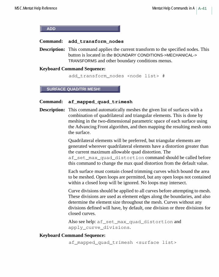
A-41MSC.Mentat Help Reference Mentat Help Commands in A
ADD
Command: add_transform_nodes
Description: This command applies the current transform to the specified nodes. This button is located in the BOUNDARY CONDITIONS->MECHANICAL-> TRANSFORMS and other boundary conditions menus.
Keyboard Command Sequence: add_transform_nodes <node list> #
SURFACE QUAD/TRI MESH!
Command: af_mapped_quad_trimesh
Description: This command automatically meshes the given list of surfaces with a combination of quadrilateral and triangular elements. This is done by meshing in the two-dimensional parametric space of each surface using the Advancing Front algorithm, and then mapping the resulting mesh onto the surface.
Quadrilateral elements will be preferred, but triangular elements are generated wherever quadrilateral elements have a distortion greater than the current maximum allowable quad distortion. The af_set_max_quad_distortion command should be called before this command to change the max quad distortion from the default value.
Each surface must contain closed trimming curves which bound the area to be meshed. Open loops are permitted, but any open loops not contained within a closed loop will be ignored. No loops may intersect.
Curve divisions should be applied to all curves before attempting to mesh. These divisions are used as element edges along the boundaries, and also determine the element size throughout the mesh. Curves without any divisions defined will have, by default, one division or three divisions for closed curves.
Also see help: af_set_max_quad_distortion and apply_curve_divisions.
Keyboard Command Sequence: af_mapped_quad_trimesh <surface list>
ADD
SURFACE QUAD/TRI MESH!
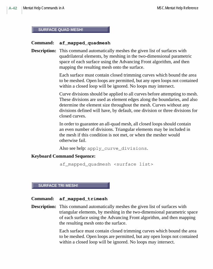
Mentat Help Commands in A MSC.Mentat Help ReferenceA-42
SURFACE QUAD MESH!
Command: af_mapped_quadmesh
Description: This command automatically meshes the given list of surfaces with quadrilateral elements, by meshing in the two-dimensional parametric space of each surface using the Advancing Front algorithm, and then mapping the resulting mesh onto the surface.
Each surface must contain closed trimming curves which bound the area to be meshed. Open loops are permitted, but any open loops not contained within a closed loop will be ignored. No loops may intersect.
Curve divisions should be applied to all curves before attempting to mesh. These divisions are used as element edges along the boundaries, and also determine the element size throughout the mesh. Curves without any divisions defined will have, by default, one division or three divisions for closed curves.
In order to guarantee an all-quad mesh, all closed loops should contain an even number of divisions. Triangular elements may be included in the mesh if this condition is not met, or when the mesher would otherwise fail.
Also see help: apply_curve_divisions.
Keyboard Command Sequence:
af_mapped_quadmesh <surface list>
SURFACE TRI MESH!
Command: af_mapped_trimesh
Description: This command automatically meshes the given list of surfaces with triangular elements, by meshing in the two-dimensional parametric space of each surface using the Advancing Front algorithm, and then mapping the resulting mesh onto the surface.
Each surface must contain closed trimming curves which bound the area to be meshed. Open loops are permitted, but any open loops not contained within a closed loop will be ignored. No loops may intersect.
SURFACE QUAD MESH!
SURFACE TRI MESH!

A-43MSC.Mentat Help Reference Mentat Help Commands in A
Curve divisions should be applied to all curves before attempting to mesh. These divisions are used as element edges along the boundaries, and also determine the element size throughout the mesh. Curves without any divisions defined will have, by default, one division or three divisions for closed curves.
Also see help: apply_curve_divisions.
Keyboard Command Sequence:
af_mapped_trimesh <surface list>
QUAD/TRI MESH!
Command: af_planar_quad_trimesh
Description: This command automatically meshes the given list of curves with a combination of quadrilateral and triangular elements using the Advancing Front algorithm. Quadrilateral elements will be preferred, but triangular elements are generated wherever quadrilateral elements have a distortion greater than the current maximum allowable quad distortion. The af_set_max_quad_distortion command should be called before this command to change the max quad distortion from the default value.
The given curves must form at least one closed loop and lie in a unique plane. Open loops are permitted, but any open loops not contained within a closed loop will be ignored. No loops may intersect.
Curve divisions should be applied to all curves before attempting to mesh. These divisions are used as element edges along the boundaries, and also determine the element size throughout the mesh. Curves without any divisions defined will have, by default, one division or three divisions for closed curves.
Also see help: af_set_max_quad_distortion and apply_curve_divisions.
Keyboard Command Sequence:
af_planar_quad_trimesh <curve list>
QUAD/TRI MESH!
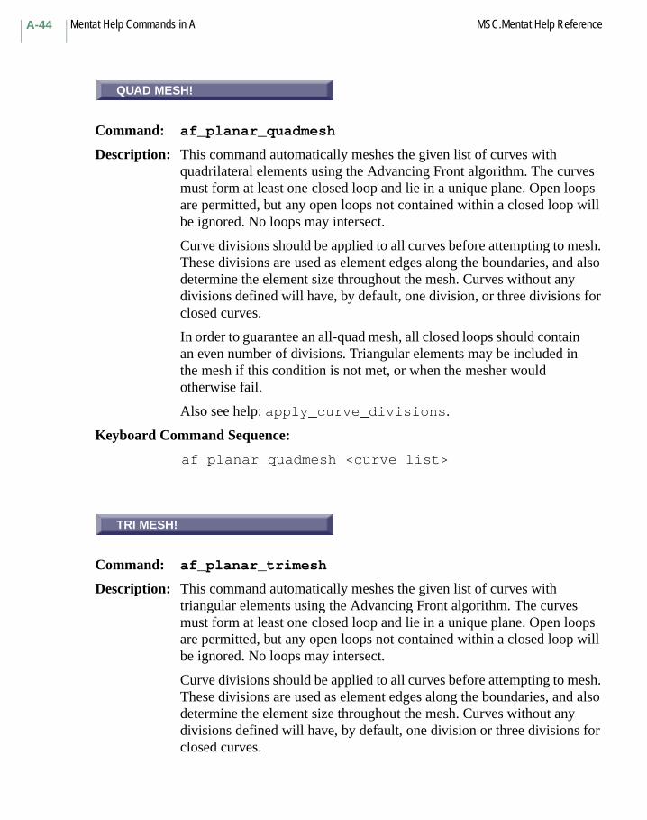
Mentat Help Commands in A MSC.Mentat Help ReferenceA-44
QUAD MESH!
Command: af_planar_quadmesh
Description: This command automatically meshes the given list of curves with quadrilateral elements using the Advancing Front algorithm. The curves must form at least one closed loop and lie in a unique plane. Open loops are permitted, but any open loops not contained within a closed loop will be ignored. No loops may intersect.
Curve divisions should be applied to all curves before attempting to mesh. These divisions are used as element edges along the boundaries, and also determine the element size throughout the mesh. Curves without any divisions defined will have, by default, one division, or three divisions for closed curves.
In order to guarantee an all-quad mesh, all closed loops should contain an even number of divisions. Triangular elements may be included in the mesh if this condition is not met, or when the mesher would otherwise fail.
Also see help: apply_curve_divisions.
Keyboard Command Sequence:
af_planar_quadmesh <curve list>
TRI MESH!
Command: af_planar_trimesh
Description: This command automatically meshes the given list of curves with triangular elements using the Advancing Front algorithm. The curves must form at least one closed loop and lie in a unique plane. Open loops are permitted, but any open loops not contained within a closed loop will be ignored. No loops may intersect.
Curve divisions should be applied to all curves before attempting to mesh. These divisions are used as element edges along the boundaries, and also determine the element size throughout the mesh. Curves without any divisions defined will have, by default, one division or three divisions for closed curves.
QUAD MESH!
TRI MESH!

A-45MSC.Mentat Help Reference Mentat Help Commands in A
Also see help: apply_curve_divisions.
Keyboard Command Sequence: af_planar_trimesh <curve list>
MAX QUAD DISTORTION
Command: af_set_max_quad_distortion
Description: Use this command to set the maximum allowed distortion for quadrilateral elements in a quad/tri mixed mesh to be created by the af_planar_quad_trimesh command. The parameter entered should be between 0.0 (no distortion allowed; results in an all-triangular mesh) and 1.0 (full distortion allowed; results in an all-quadrilateral mesh). Values entered outside of this range are reverted to the closest limit.
In the af_planar_quad_trimesh command, quadrilateral elements are preferred. For this reason, entering a low (< 0.5) value for this parameter is of little practical value. Doing so may cause the mesher to be very slow, and the resulting mesh will likely be largely comprised of triangular elements. To generate an all-triangular mesh, use one of the tri-mesh commands.
Keyboard Command Sequence: af_set_max_quad_distortion <max quad distortion>
alias
Command: alias
Description: Like the UNIX alias command, the MSC.Marc Mentat alias command associates a real command with a character string that represents the command and can be used in its place. You create an alias for a command (or even for an alias) by entering the alias command followed by the existing command or alias, followed in turn by the new alias name. If an alias has already been used, you are prompted to that effect. This button is a text box located in the UTILITIES->ALIASES menu.
Keyboard Command Sequence: alias <alias name> <command string>
MAX QUAD DISTORTION
alias

Mentat Help Commands in A MSC.Mentat Help ReferenceA-46
ALIGN
Command: align_orient
Description: This command sets the type of the current orientation to 3d_aniso and determines the user-defined vectors from the three specified points representing a cartesian coordinate system.
This command should only be used for orientations that are applied to 3-D elements.
Keyboard Command Sequence: align_orient <X, Y, Z coordinates of origin>
<X, Y, Z coordinates of point on x-axis><X, Y, Z coordinates of point on in x-y plane>
ALIGN SHELLS
Command: align_shells
Description: This command picks one element and makes all consecutively reached elements to have the same node orientation.
Keyboard Command Sequence: align_shells < element >
ALIGN
Command: align_transform
Description: This command sets up an alignment for future transformations. The alignment you choose will define a vector along which transformations are directed for commands that use alignment.
You must enter an origin point, a point on the x-axis of the transformed system, and a point on the y-axis of the transformed system.
Keyboard Command Sequence:
align_transform <origin point> <x-axis point><y-axis point>
ALIGN
ALIGN SHELLS
ALIGN
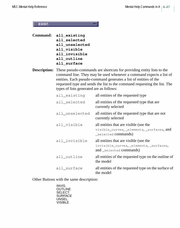
A-47MSC.Mentat Help Reference Mentat Help Commands in A
EXIST.
Command: all_existingall_selectedall_unselectedall_visibleall_invisibleall_outlineall_surface
Description: These pseudo-commands are shortcuts for providing entity lists to the command line. They may be used whenever a command expects a list of entities. Each pseudo-command generates a list of entities of the requested type and sends the list to the command requesting the list. The types of lists generated are as follows:
all_existing all entities of the requested type
all_selected all entities of the requested type that are currently selected
all_unselected all entities of the requested type that are not currently selected
all_visible all entities that are visible (see the visible_curves, _elements, _surfaces, and _selected commands)
all_invisible all entities that are visible (see the invisible_curves, _elements, _surfaces, and _selected commands)
all_outline all entities of the requested type on the outline of the model
all_surface all entities of the requested type on the surface of the model
Other Buttons with the same description:
INVIS.OUTLINESELECT.SURFACEUNSEL.VISIBLE
EXIST.
Mentat Help Commands in A MSC.Mentat Help ReferenceA-48
INTERRUPT
Description: This button interrupts the playing of animation files. Playing may be continued by pressing the RESUME button.
RESUME
Description: This button continues the playing of animation files. Playing may be interrupted with the INTERRUPT button.
ANIMATION
Menu: ANIMATION
Description: This menu contains commands for creating and playing animation files. Animation files enable you to save a set of graphics display windows and play them back like a movie. This menu is located in the RESULTS-> MORE menu.
ALL
Command: animation_index_all
Description: This command toggles animation-play-all-indices. When ON, the animation_play command plays back all the animation files that start with the current animation base filename. When OFF, the animation_play command plays back only those animation files which have indices between the begin and end index values currently set for animation playback (see animation_index_begin and animation_index_end).
In other words, when animation_index_all is ON, all the animation files that have been created with the current animation base filename will be played back, and when animation_index_all is
INTERRUPT
RESUME
ANIMATION
ALL

A-49MSC.Mentat Help Reference Mentat Help Commands in A
OFF, only a range of those files will be played back. By default, animation_index_all is on.
Keyboard Command Sequence:
animation_index_all <on or off>
Another Button with the same description:
BEGIN TO END
BEGIN
Command: animation_index_begin
Description: This command sets the beginning animation file playback index. This value is valid only if animation_index_all is OFF (see animation_index_all). When this value is valid, the animation_play command plays back a range of animation files that have been created with the current animation base filename, starting with this index.
Keyboard Command Sequence:
animation_index_begin <begin index>
CURRENT
Command: animation_index_current
Description: This command sets the current animation file playback index. This value is valid only if an animation playback sequence has been temporarily interrupted (with a mouse-click or keystroke). When animation is resumed, it starts animating at this index.
Keyboard Command Sequence:
animation_index_current <current index>
BEGIN
CURRENT
Mentat Help Commands in A MSC.Mentat Help ReferenceA-50
END
Command: animation_index_end
Description: This command sets the end of the animation file playback index. This value is valid only if animation_index_all is OFF (see animation_index_all). When this value is valid, the animation_play command plays back a range of animation files that have been created with the current animation base filename, ending with this index.
Keyboard Command Sequence:
animation_index_end <end index>
INDEX
Command: animation_index_save
Description: This command sets the next animation file save index. The animation_save command appends this index to the current animation base filename, to create the name of the file in which the current display lists are to be stored. The save index is automatically set to zero each time a new animation base filename is entered. The save index is automatically incremented after each animation_save command.
Note: If you are saving more than 900 animation sequences, this number should be set to 1000.
Keyboard Command Sequence:
animation_index_save <save index>
END
INDEX
A-51MSC.Mentat Help Reference Mentat Help Commands in A
BASE FILE NAME
Command: animation_name
Description: This command sets the animation base filename. The base filename is used by both the animation_save and the animation_play commands. The save or current index is appended to the base filename to create the actual filename for saving or playing back display lists. By default, animation_name is set to the base file name of the post file.
Keyboard Command Sequence:
animation_name <filename>
DELAY
Command: animation_pause
Description: This command sets the number of seconds to pause between frames during animation playback. By default, animation_pause is zero.
Keyboard Command Sequence:
animation_pause <seconds>
Another Button with the same description:
PAUSE
PLAY
Command: animation_play
Description: This command plays back display lists which have previously been saved with the animation_save command.
Keyboard Command Sequence:
animation_play
BASE FILE NAME
DELAY
PLAY
Mentat Help Commands in A MSC.Mentat Help ReferenceA-52
REPEAT
Command: animation_repeat
Description: This command toggles animation repeat mode. When OFF, the animation_play command plays, just once, the animation files that start with the current animation base filename. When ON, the animation_play command plays back those files over and over again. Either way, playback can be interrupted with a mouse-click or keystroke. By default, animation_repeat is OFF.
Keyboard Command Sequence:
animation_repeat <on or off>
Another Button with the same description:
SINGLE PLAY
FORWARD
Command: animation_reverse
Description: This command toggles animation reverse mode. When OFF, the animation_play command plays back, in ascending order, the animation files that start with the current animation base filename. When ON, the animation_play command plays back, in ascending order, those files. By default, animation_reverse is OFF.
Keyboard Command Sequence:
animation_reverse <on or off>
Another Button with the same description:
REVERSE
REPEAT
FORWARD
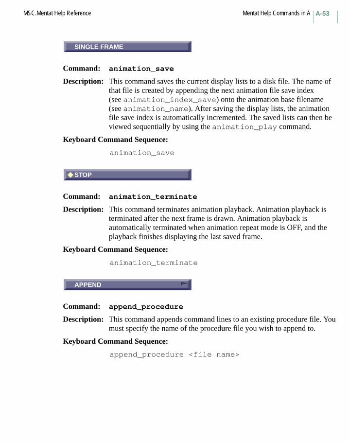
A-53MSC.Mentat Help Reference Mentat Help Commands in A
SINGLE FRAME
Command: animation_save
Description: This command saves the current display lists to a disk file. The name of that file is created by appending the next animation file save index (see animation_index_save) onto the animation base filename (see animation_name). After saving the display lists, the animation file save index is automatically incremented. The saved lists can then be viewed sequentially by using the animation_play command.
Keyboard Command Sequence:
animation_save
STOP
Command: animation_terminate
Description: This command terminates animation playback. Animation playback is terminated after the next frame is drawn. Animation playback is automatically terminated when animation repeat mode is OFF, and the playback finishes displaying the last saved frame.
Keyboard Command Sequence:
animation_terminate
APPEND
Command: append_procedure
Description: This command appends command lines to an existing procedure file. You must specify the name of the procedure file you wish to append to.
Keyboard Command Sequence:
append_procedure <file name>
SINGLE FRAME
STOP
APPEND
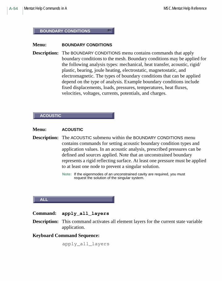
Mentat Help Commands in A MSC.Mentat Help ReferenceA-54
BOUNDARY CONDITIONS
Menu: BOUNDARY CONDITIONS
Description: The BOUNDARY CONDITIONS menu contains commands that apply boundary conditions to the mesh. Boundary conditions may be applied for the following analysis types: mechanical, heat transfer, acoustic, rigid/plastic, bearing, joule heating, electrostatic, magnetostatic, and electromagnetic. The types of boundary conditions that can be applied depend on the type of analysis. Example boundary conditions include fixed displacements, loads, pressures, temperatures, heat fluxes, velocities, voltages, currents, potentials, and charges.
ACOUSTIC
Menu: ACOUSTIC
Description: The ACOUSTIC submenu within the BOUNDARY CONDITIONS menu contains commands for setting acoustic boundary condition types and application values. In an acoustic analysis, prescribed pressures can be defined and sources applied. Note that an unconstrained boundary represents a rigid reflecting surface. At least one pressure must be applied to at least one node to prevent a singular solution.
Note: If the eigenmodes of an unconstrained cavity are required, you must request the solution of the singular system.
ALL
Command: apply_all_layers
Description: This command activates all element layers for the current state variable application.
Keyboard Command Sequence:
apply_all_layers
BOUNDARY CONDITIONS
ACOUSTIC
ALL

A-55MSC.Mentat Help Reference Mentat Help Commands in A
BEARING
Menu: BEARING
Description: The BEARING submenu within the BOUNDARY CONDITIONS menu contains commands for setting bearing boundary condition types and application values. In a hydrodynamic bearing analysis, the lubrication pressure can be defined and mass flow rates be applied. An unconstrained boundary represents no mass flow across that boundary. To ensure a nonsingular solution, a pressure must be defined for at least one point or the restrictor option be used.
APPLY CURVE DIVISIONS
Command: apply_curve_divisions
Description: This command will apply curve divisions to chosen curves, in accordance with the current specified curve division type and associated parameters, as well as the specified division restriction.
Also see help: curve_div_type and curve_div_rest
Keyboard Command Sequence:
apply_curve_divisions <curve list>
DISPLACEMENT X
Command: apply_dofclear_apply_dof
Description: These commands add and clear the indicated degree of freedom from the current boundary condition application. The button text will be the name of the boundary condition, such as FLUX for Joule heating, PRESSURE for acoustic, etc.
Keyboard Command Sequence:
apply_dof <dof name>clear_apply_dof <dof name>
BEARING
APPLY CURVE DIVISIONS
DISPLACEMENT X

Mentat Help Commands in A MSC.Mentat Help ReferenceA-56
ELECTROMAGNETIC
Menu: ELECTROMAGNETIC
Description: The ELECTROMAGNETIC submenu within the BOUNDARY CONDITIONS menu contains commands for setting electromagnetic boundary condition types and application values. In electromagnetic analysis, the potential can be defined and charges and/or currents may be applied. In a harmonic analysis, both the magnitude and phase are required.
ELECTROSTATIC
Menu: ELECTROSTATIC
Description: The ELECTROSTATIC submenu within the BOUNDARY CONDITIONS menu contains commands for setting electrostatic boundary condition types and application values. In an electrostatic analysis, the scalar potential may be defined and charges may be applied. It is necessary to define the scalar potential by at least one node to ensure a nonsingular system.
JOULE
Menu: JOULE
Description: The JOULE submenu within the BOUNDARY CONDITIONS menu contains commands for setting joule boundary condition types and application values. In a Joule heating analysis, besides the conventional heat transfer boundary conditions, you can define voltages and apply currents. At least one node must have a constrained voltage to ensure that a nonsingular system occurs and a solution is obtainable.
ELECTROMAGNETIC
ELECTROSTATIC
JOULE

A-57MSC.Mentat Help Reference Mentat Help Commands in A
LAYERS
Command: apply_layers
Description: This command activates element layers for the current state variable application. Element layers are specified as integers beginning at 1.
Keyboard Command Sequence: apply_layers <layer numbers>
MAGNETOSTATIC
Menu: MAGNETOSTATIC
Description: The MAGNETOSTATIC submenu within the BOUNDARY CONDITIONS menu contains commands for setting magnetostatic boundary condition types and application values. In magnetostatic analysis, you can define the vector potential at nodes and apply currents. The potential should be applied at one point to ensure a nonsingular problem.
MECHANICAL
Menu: MECHANICAL
Description: The MECHANICAL submenu within the BOUNDARY CONDITIONS menu contains commands for setting mechanical boundary condition types and application values.
NAME
Command: apply_name
Description: This command sets or changes the name of the current application.
A boundary condition application is a set of information that completely defines a boundary condition. Each application contains the type of boundary condition, the degrees of freedom and their corresponding applied values, optional tables or functions that apply to the values, and the geometric and FEM entities affected. Multiple applications may be defined and are stored in the list of currently defined applications.
Keyboard Command Sequence: apply_name <application name>
LAYERS
MAGNETOSTATIC
MECHANICAL
NAME
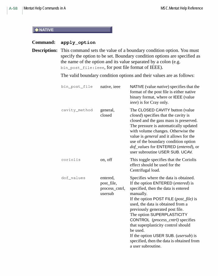
Mentat Help Commands in A MSC.Mentat Help ReferenceA-58
# NATIVE
Command: apply_option
Description: This command sets the value of a boundary condition option. You must specify the option to be set. Boundary condition options are specified as the name of the option and its value separated by a colon (e.g. bin_post_file:ieee, for post file format of IEEE).
The valid boundary condition options and their values are as follows:
bin_post_file native, ieee NATIVE (value native) specifies that the format of the post file is either native binary format, where or IEEE (value ieee) is for Cray only.
cavity_method general, closed
The CLOSED CAVITY button (value closed) specifies that the cavity is closed and the gass mass is preserved. The pressure is automatically updated with volume changes. Otherwise the value is general and it allows for the use of the boundary condition option dof_values for ENTERED (entered), or user subroutine USER SUB. UCAV.
coriolis on, off This toggle specifies that the Coriolis effect should be used for the Centrifugal load.
dof_values entered,post_file,process_cntrl,usersub
Specifies where the data is obtained. If the option ENTERED (entered) is specified, then the data is entered manually.If the option POST FILE (post_file) is used, the data is obtained from a previously generated post file.The option SUPERPLASTICITY CONTROL (process_cntrl) specifies that superplasticity control should be used.If the option USER SUB. (usersub) is specified, then the data is obtained from a user subroutine.
NATIVE
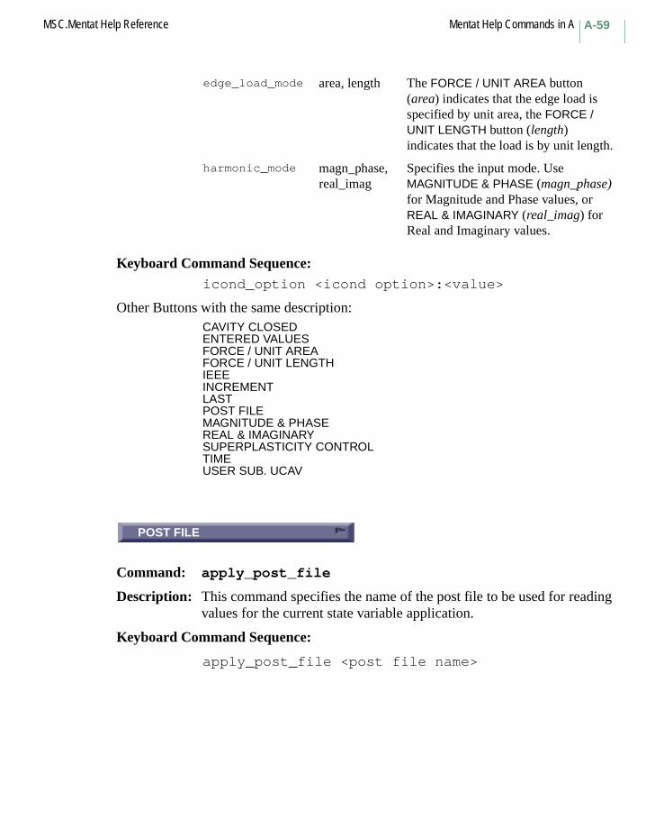
A-59MSC.Mentat Help Reference Mentat Help Commands in A
Keyboard Command Sequence: icond_option <icond option>:<value>
Other Buttons with the same description:CAVITY CLOSEDENTERED VALUESFORCE / UNIT AREAFORCE / UNIT LENGTHIEEEINCREMENTLASTPOST FILEMAGNITUDE & PHASEREAL & IMAGINARYSUPERPLASTICITY CONTROLTIMEUSER SUB. UCAV
POST FILE
Command: apply_post_file
Description: This command specifies the name of the post file to be used for reading values for the current state variable application.
Keyboard Command Sequence:
apply_post_file <post file name>
edge_load_mode area, length The FORCE / UNIT AREA button (area) indicates that the edge load is specified by unit area, the FORCE / UNIT LENGTH button (length) indicates that the load is by unit length.
harmonic_mode magn_phase, real_imag
Specifies the input mode. Use MAGNITUDE & PHASE (magn_phase) for Magnitude and Phase values, or REAL & IMAGINARY (real_imag) for Real and Imaginary values.
POST FILE

Mentat Help Commands in A MSC.Mentat Help ReferenceA-60
FIRST INCREMENT
Command: apply_post_increment
Description: This command specifies the first increment to be read from the post file to provide values for the state variable application.
Keyboard Command Sequence:
apply_post_increment <increment number>
Another Button with the same description:
INCREMENT
# STEPS
Command: apply_post_steps
Description: This command specifies the number of increments (steps) to be read from the post file to provide values for the state variable application.
Keyboard Command Sequence: apply_post_steps <number of increments>
RADIATION
Menu: RADIATION
Description: Radiation Boundary Conditions may be applied to element edges and faces. The emission of radiation may be toggled ON or OFF, and the temperature at infinity may be set. Shells may emit from either the top or bottom while continuum elements emit only from the top or outer direction. If neither side emits, then the elements only shadow other elements.
The radiation boundary conditions are used in the viewfactor computation. Emissivities are set in the material properties for heat transfer.
FIRST INCREMENT
# STEPS
RADIATION
A-61MSC.Mentat Help Reference Mentat Help Commands in A
TABLE
Command: apply_table
Description: This command selects a table to be applied to a boundary condition. You must specify a slot name and a previously defined table by name. Slot names are specified by a quantity name appended with a slot number (for example, x0).
A table is a function of one variable, i.e. y = f(x), that is applied to the corresponding application value. The table is commonly a function of a variable such as time, frequency, temperature, position. These tables are used by the analysis program to define the spatial or temporal variation of a quantity.
Keyboard Command Sequence: apply_table <quantity name><slot number>
<table name>
THERMAL
Menu: THERMAL
Description: The THERMAL submenu within the BOUNDARY CONDITIONS menu contains commands for setting thermal boundary condition types and application values. In heat transfer analyses, you can define a fixed temperature to a node and apply fluxes to the surface or volume. The film boundary conditions allow the definition of corrective boundary conditions. A prescribed temperature or film condition should be applied somewhere in the model to ensure a nonsingular system if a steady state analysis is performed.
EDGE CURRENT
Command: apply_type
Description: This command selects the boundary condition type of the current application. If the current application does not have any values set then this command simply changes the boundary condition type. If the current application has values set, then this command creates a new application in addition to setting the type. (This feature saves users from having to
TABLE
THERMAL
EDGE CURRENT
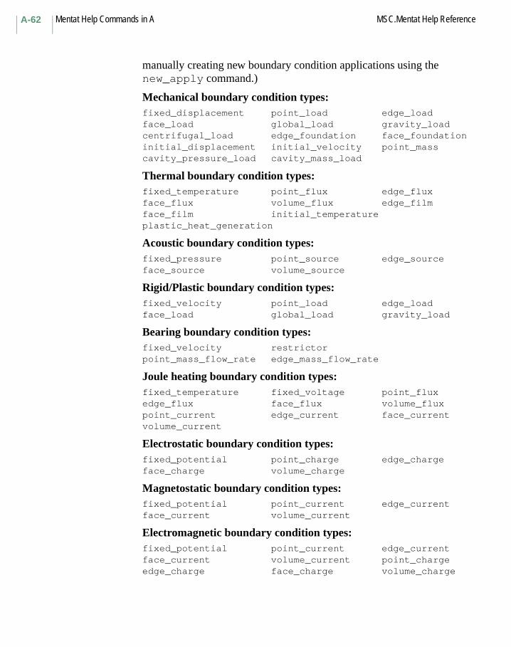
Mentat Help Commands in A MSC.Mentat Help ReferenceA-62
manually creating new boundary condition applications using the new_apply command.)
Mechanical boundary condition types:fixed_displacement point_load edge_loadface_load global_load gravity_loadcentrifugal_load edge_foundation face_foundationinitial_displacement initial_velocity point_masscavity_pressure_load cavity_mass_load
Thermal boundary condition types:fixed_temperature point_flux edge_fluxface_flux volume_flux edge_filmface_film initial_temperatureplastic_heat_generation
Acoustic boundary condition types:fixed_pressure point_source edge_sourceface_source volume_source
Rigid/Plastic boundary condition types: fixed_velocity point_load edge_loadface_load global_load gravity_load
Bearing boundary condition types:fixed_velocity restrictorpoint_mass_flow_rate edge_mass_flow_rate
Joule heating boundary condition types:fixed_temperature fixed_voltage point_fluxedge_flux face_flux volume_fluxpoint_current edge_current face_currentvolume_current
Electrostatic boundary condition types:fixed_potential point_charge edge_chargeface_charge volume_charge
Magnetostatic boundary condition types:fixed_potential point_current edge_currentface_current volume_current
Electromagnetic boundary condition types:fixed_potential point_current edge_currentface_current volume_current point_chargeedge_charge face_charge volume_charge

A-63MSC.Mentat Help Reference Mentat Help Commands in A
Keyboard Command Sequence: apply_type <boundary condition type>
Other Buttons with the same description:GLOBAL LOADGRAVITY LOADOKPERMANENT MAGNETIZATIONVOLUME CHARGEVOLUME CURRENT
DRAG COEFFICIENT
Command: apply_value
Description: This command sets the value for a particular quantity in the current application. You must specify the quantity name and its value.
Keyboard Command Sequence: apply_value <quantity or dof name> <value>
Other Buttons with the same description:GRAVITY CONSTANTINERTIA COEFFICIENTINNER MASS DENSITYINNER SURFACE ELEVNEGATIVEOUTER MASS DENSITYOUTER SURFACE ELEVPOSITIVESEA BED ELEVATIONVXVYVZWAVE DIRECTION COS 1WAVE DIRECTION COS 2WAVE HEIGHTWAVE PERIODWAVE PHASEX CURRENTX GRADIENTX1X2Y CURRENTY GRADIENTY1Y2Z CURRENTZ GRADIENTZ1Z2
DRAG COEFFICIENT
Mentat Help Commands in A MSC.Mentat Help ReferenceA-64
STATE VARIABLE ID
Command: apply_variable
Description: This command specifies the identifier of the state variable for the current state variable application. Temperature is always the first state variable at a point.
Keyboard Command Sequence: apply_variable <state variable id>
# FACETS
Command: arrow_facets
Description: This command allows you to set the number of circular facets used when pre- and postprocessing arrows are plotted in solid mode. Also, be sure to use the arrows_solid command to select solid plotting of arrows (wireframe plotting is the default). The default number of facets is eight.
Also see arrows_solid and set_arrow_lines.
Keyboard Command Sequence: arrow_facets <# of facets>
LENGTH
Command: arrow_length
Description: This command allows you to set the absolute length of preprocessing arrows. Be sure to use the set_auto_arrow command to turn off the auto-arrow-length mode which by default is ON. The default arrow length (when this mode is off) is 0.2.
Also see set_auto_arrow and auto_arrow_length.
Keyboard Command Sequence:
arrow_length <length>
STATE VARIABLE ID
# FACETS
LENGTH
A-65MSC.Mentat Help Reference Mentat Help Commands in A
SOLID
Command: arrows_wireframearrows_solid
Description: These commands allow you to select the overall plot style of pre- and postprocessing arrows to be either wireframe or solid. Wireframe plotting is the default. If solid plotting is selected, you may also set the number of circular facets used to draw each arrow, and you may select whether or not the edges of the facets should be drawn.
Also see arrow_facets and set_arrow_lines.
Keyboard Command Sequence: arrows_wireframearrows_solid
Another Button with the same description:WIREFRAME
ARRUDA-BOYCE
Command: boyce_1993
Description: Elastomer Free Energy Function
Number of coefficients: 1
Reference: Ellen M. Arruda and Boyce, Mary C. "A Three-Dimensional Constitutive Model For the Large Stretch Behavior of Rubber Elastic Materials." J.Mech. Phys. Solids Vol. 41, No. 2, pp. 389-412
Parameter:N – The number of mers in a typcial polymer chain Specified by the user.
Coefficient:nkT – Determined by the fitter
n: Number of Polymer chains per unit volume k: Boltzmann constant T: Temperature
For this model, the calculation of the Bulk Modulus is not required by the MSC.Marc program. A volumetric test do not need to be supplied.
SOLID
ARRUDA-BOYCE

Mentat Help Commands in A MSC.Mentat Help ReferenceA-66
ASSOC
Subroutine: ASSOC
Description: The user subroutine ASSOC allows you to define the flow direction for plasticity when used in conjunction with the Generalized Plasticity option. The default is the associated flow law with the von Mises (J2) yield surface. ASSOC is used in conjunction with user subroutines SINCER, YIEL, and ZERO.
ATTACH
Menu: ATTACH
Description: This menu contains commands for associating a mesh with the underlying geometry. The following associations can be made:
• a node can be attached to a point • an element edge can be attached to a curve• an element face can be attached to a surface.
In addition to the commands in this menu, the automatic mesh generators in the AUTOMESH menu and the conversion operations from GEOMETRY to MESH in the CONVERT menu, automatically attach the mesh to the geometry.
Nodes which are attached to a point always have the same position as the point. Nodes of edges which are attached to a curve always lie on that curve and nodes of faces which are attached to a surface always lie on that surface. Note that this implies that the common node of two edges which are attached to different curves must lie on the intersection of the curves. Similarly, the common nodes of two faces which are attached to different surfaces must lie on the intersection of the two surfaces. The automatic mesh generators and the mesh generation commands that modify either the mesh or the geometry guarantee that this is always the case. For example, if one of the curves is moved or otherwise changed, the common node is repositioned automatically to the new point of intersection. If that point cannot be found, the operation is not permitted and an error message is issued.
ASSOC
ATTACH
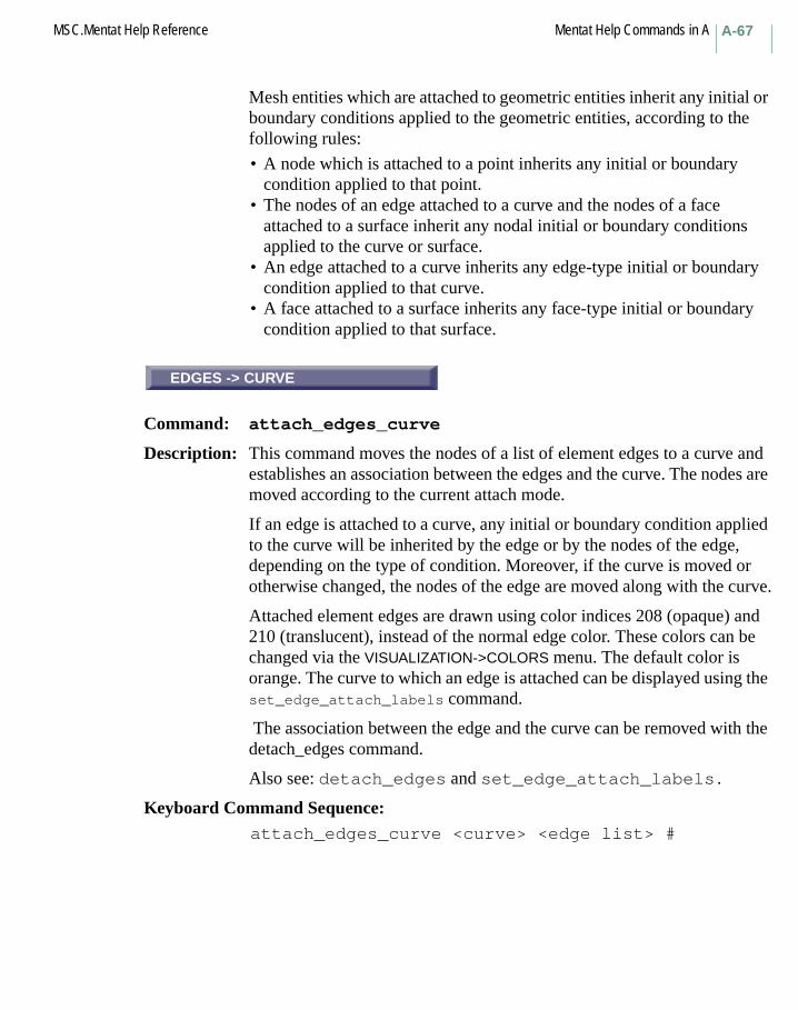
A-67MSC.Mentat Help Reference Mentat Help Commands in A
Mesh entities which are attached to geometric entities inherit any initial or boundary conditions applied to the geometric entities, according to the following rules:
• A node which is attached to a point inherits any initial or boundary condition applied to that point.
• The nodes of an edge attached to a curve and the nodes of a face attached to a surface inherit any nodal initial or boundary conditions applied to the curve or surface.
• An edge attached to a curve inherits any edge-type initial or boundary condition applied to that curve.
• A face attached to a surface inherits any face-type initial or boundary condition applied to that surface.
EDGES -> CURVE
Command: attach_edges_curve
Description: This command moves the nodes of a list of element edges to a curve and establishes an association between the edges and the curve. The nodes are moved according to the current attach mode.
If an edge is attached to a curve, any initial or boundary condition applied to the curve will be inherited by the edge or by the nodes of the edge, depending on the type of condition. Moreover, if the curve is moved or otherwise changed, the nodes of the edge are moved along with the curve.
Attached element edges are drawn using color indices 208 (opaque) and 210 (translucent), instead of the normal edge color. These colors can be changed via the VISUALIZATION->COLORS menu. The default color is orange. The curve to which an edge is attached can be displayed using the set_edge_attach_labels command.
The association between the edge and the curve can be removed with the detach_edges command.
Also see: detach_edges and set_edge_attach_labels.
Keyboard Command Sequence: attach_edges_curve <curve> <edge list> #
EDGES -> CURVE

Mentat Help Commands in A MSC.Mentat Help ReferenceA-68
ELEMENTS -> CURVE
Command: attach_elements_curve
Description: This command attaches the first edge (edge 0) of a list of elements to a curve. Only the first edge of the line elements in the list will be attached to the curve. Elements of other classes (if any) are disregarded.
Also see: attach_edges_curve.
Keyboard Command Sequence: attach_elements_curve <curve> <element list> #
ELEMENTS -> SURFACE
Command: attach_elements_surface
Description: This command attaches the first face (face 0) of a list of elements to a surface. Only the first face of the triangular and quadrilateral elements in the list will be attached to the surface. Elements of other classes (if any) are disregarded.
Also see: attach_faces_surface.
Keyboard Command Sequence: attach_elements_surface <surface>
<element list> #
FACES -> SURFACE
Command: attach_faces_surface
Description: This command moves the nodes of a list of element faces to a surface and establishes an association between the faces and the surface. The nodes are moved according to the current attach mode.
If a face is attached to a surface, any initial or boundary condition applied to the surface will be inherited by the face or by the nodes of the face, depending on the type of condition. Moreover, if the surface is moved or otherwise changed, the nodes of the face are moved along with the surface.
Attached element faces are drawn using color indices 209 (opaque) and 211 (translucent), instead of the normal face color. These colors can be
ELEMENTS -> CURVE
ELEMENTS -> SURFACE
FACES -> SURFACE

A-69MSC.Mentat Help Reference Mentat Help Commands in A
changed via the VISUALIZATION->COLORS menu. The default color is dark blue. The surface to which a face is attached can be displayed using the set_face_attach_labels command.
The association between the face and the surface can be removed with the detach_faces command.
Also see: detach_faces and set_face_attach_labels.
Keyboard Command Sequence: attach_faces_surface <surface> <face list> #
CLOSEST
Command: attach_mode_closest
Description: This command switches the attach mode to "closest". In this mode, the commands:
• attach_edges_curve• attach_faces_surface• attach_elements_curve• attach_elements_surface
move the nodes of the edges or faces that must be attached to the point on the curve or surface closest to their original position.
Also see: attach_mode_directed, attach_edges_curve, attach_faces_surface, attach_elements_curve, and attach_elements_surface
Keyboard Command Sequence: attach_mode_closest
CLOSEST

Mentat Help Commands in A MSC.Mentat Help ReferenceA-70
DIRECTED
Command: attach_mode_directed
Description: This command switches the attach mode to "directed". In this mode, the commands:
• attach_edges_curve• attach_faces_surface• attach_elements_curve• attach_elements_surface
move the nodes of the edges or faces that must be attached in a particular direction to the curve or surface. The direction can be set by the set_attach_direction command.
Also see: attach_mode_closest, set_attach_direction, attach_edges_curve, attach_faces_surface, attach_elements_curve, and attach_elements_surface.
Keyboard Command Sequence: attach_mode_directed
NODES -> POINT
Command: attach_nodes_point
Description: This command moves a list of nodes to a point and establishes an association between the nodes and the point.
If a node is attached to a point, any initial or boundary condition applied to the point will be inherited by the node. Moreover, if the point is moved, the node is moved along with the point.
Attached nodes are drawn as circles as opposed to the usual squares. The point to which a node is attached can be displayed using the set_node_attach_labels command.
The association between the node and the point can be removed with the detach_nodes command.
Also see: detach_nodes, and set_node_attach_labels.
Keyboard Command Sequence: attach_nodes_point <point> <node list> #
DIRECTED
NODES -> POINT
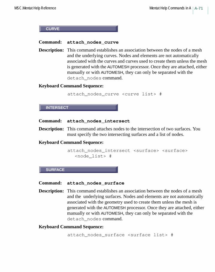
A-71MSC.Mentat Help Reference Mentat Help Commands in A
CURVE
Command: attach_nodes_curve
Description: This command establishes an association between the nodes of a mesh and the underlying curves. Nodes and elements are not automatically associated with the curves and curves used to create them unless the mesh is generated with the AUTOMESH processor. Once they are attached, either manually or with AUTOMESH, they can only be separated with the detach_nodes command.
Keyboard Command Sequence:
attach_nodes_curve <curve list> #
INTERSECT
Command: attach_nodes_intersect
Description: This command attaches nodes to the intersection of two surfaces. You must specify the two intersecting surfaces and a list of nodes.
Keyboard Command Sequence:
attach_nodes_intersect <surface> <surface><node_list> #
SURFACE
Command: attach_nodes_surface
Description: This command establishes an association between the nodes of a mesh and the underlying surfaces. Nodes and elements are not automatically associated with the geometry used to create them unless the mesh is generated with the AUTOMESH processor. Once they are attached, either manually or with AUTOMESH, they can only be separated with the detach_nodes command.
Keyboard Command Sequence:
attach_nodes_surface <surface list> #
CURVE
INTERSECT
SURFACE

Mentat Help Commands in A MSC.Mentat Help ReferenceA-72
FACTOR
Command: auto_arrow_length
Description: This command allows you to set the length of preprocessing arrows, relative to the overall size of the model. The default auto-arrow-length mode should be on (but can be turned off with the set_auto_arrow command). The default arrow length fraction is 0.1.
Also see set_auto_arrow and arrow_length.
Keyboard Command Sequence:
auto_arrow_length <fraction>
AUTOMESH
Menu: AUTOMESH
Description: This menu contains commands used to create a mesh from existing geometry. The geometry can be in the form of planar curves, trimmed surfaces, or surface elements (for generating solid elements).
2D PLANAR MESHING
Menu: AUTOMESH 2D PLANAR
Description: This menu contains commands to create a mesh from existing 2-D geometry. The area to be meshed must be bounded by closed sets of curves.
2D REBAR MESHING
Menu: AUTOMESH 2D REBAR
Description: This menu contains commands to create a mesh from existing 2-D mesh and existing curves. The curves are meshed between intersections with 2-D mesh.
FACTOR
AUTOMESH
2D PLANAR MESHING
2D REBAR MESHING
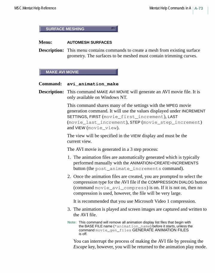
A-73MSC.Mentat Help Reference Mentat Help Commands in A
SURFACE MESHING
Menu: AUTOMESH SURFACES
Description: This menu contains commands to create a mesh from existing surface geometry. The surfaces to be meshed must contain trimming curves.
OK
Command: avi_animation_make
Description: This command MAKE AVI MOVIE will generate an AVI movie file. It is only available on Windows NT.
This command shares many of the settings with the MPEG movie generation command. It will use the values displayed under INCREMENT SETTINGS, FIRST (movie_first_increment), LAST (movie_last_increment), STEP (movie_step_increment) and VIEW (movie_view).
The view will be specified in the VIEW display and must be the current view.
The AVI movie is generated in a 3 step process:
1. The animation files are automatically generated which is typically performed manually with the ANIMATION>CREATE>INCREMENTS button (the post_animate_increments command).
2. Once the animation files are created, you are prompted to select the compression type for the AVI file if the COMPRESSION DIALOG button (command movie_avi_compress) is on. If it is not on, then no compression is used, however, the file will be very large.
It is recommended that you use Microsoft Video 1 compression.
3. The animation is played and screen images are captured and written to the AVI file.
Note: This command will remove all animation display list files that begin with the BASE FILE name (*animation_name) before it starts, unless the command movie_gen_files GENERATE ANIMATION FILES is off.
You can interrupt the process of making the AVI file by pressing the Escape key, however, you will be returned to the animation play mode.
SURFACE MESHING
MAKE AVI MOVIE

Mentat Help Commands in A MSC.Mentat Help ReferenceA-74
In this case, you will need to run the show_model command in the ANIMATION menu to display the model again.
Note: To generate a movie size equal to 640 x 480, you should use the startup option -sz 856 577. This provides the optimal image size for AVI movies.
Keyboard Command Sequence: avi_animation_make
DISPLACEMENT
Command: icond_type
Description: This command defines control parameters for data transfer and mesh expansion from axisymmetric analysis to 3-D analysis. The button text will be the type of initial condition, such as VELOCITY, POINT MASS, etc.
Keyboard Command Sequence:
icond_type <boundary condition type>
DISPLACEMENT
Mentat Help Commands in BSCALE FACTOR
Command: beam_3d_scale
Description: This command sets the scale factor used when drawing 3-D general beams with cross-sections shown extended to three dimensions. This scale affects only the size of the beam cross-section as it is seen in three dimensions, and it does not affect the perceived length of the beam.
Also see help: draw_beams_3d and geometry_value.
Keyboard Command Sequence:
beam_3d_scale <scale factor>
B Commands Begin with B
SCALE FACTOR
Mentat Help Commands in B MSC.Mentat Help ReferenceB-76
# ARC DIVISIONS
Command: beam_arc_divisions
Description: This command sets the number of divisions which will be used to draw arcs and circular cross-sections when drawing 3-D general beams with the beam cross-sections shown extended to three dimensions. A higher number results in the beams appearing smoother, while a lower number will enable the beams to be drawn faster.
Also see help: draw_beams_3d and geometry_value.
Keyboard Command Sequence:
beam_arc_divisions <number of divisions>
AXIS LENGTH FACTOR
Command: beam_axis_factor
Description: This command sets the length factor for drawing X-Y axes on 3-D beams. The length of the axes drawn on each beam is the length of the beam multiplied by the length factor. The axes will only be drawn if the draw_beam_axes option is on.
Also see help: draw_beam_axes.
Keyboard Command Sequence:
beam_axis_factor <factor>
# ARC DIVISIONS
AXIS LENGTH FACTOR

B-77MSC.Mentat Help Reference Mentat Help Commands in B
AXIAL FORCE
Command: post_beam_axial_forcepost_beam_momentpost_beam_shearpost_beam_torquepost_beam_bimoment
Description: Beam DiagramsThese commands deal with the drawing of beam diagrams (shear, axial force, moment, etc.) on the beam elements of the model during postprocessing. These values are plotted using the direction of the beam element as the local z-axis. The local x-axis direction must have been specified for the element geometry and be available for postprocessing via post codes 261-263 (beam_orient in the JOB RESULTS menu).
Plotting of any of the beam diagram values is activated by the post_beam_shear, post_beam_moment, and commands mentioned above. Beam diagram values must be available for postprocessing via post codes 264-270 (bm_axi_for ... bm_bi_mom in the JOB RESULTS menu).
Also see help: post_off and draw_beam_axes.
Keyboard Command Sequence:
post_beam_axial_forcepost_beam_momentpost_beam_shearpost_beam_torquepost_beam_bimoment
Other Buttons with the same description:
BEND. MOMENTBIMOMENTSHEAR FORCETORS. MOMENT
AXIAL FORCE
Mentat Help Commands in B MSC.Mentat Help ReferenceB-78
FILLED
Command: post_beam_draw_xpost_beam_draw_ypost_beam_filledpost_beam_factor
Description: Beam Diagrams AdjustmentThe values which are plotted in the local-xz plane (Vxz, Myy) and those which are plotted in the local-yz plane (Vyz, Mxx) may be independently toggled on and off by the post_beam_draw_x and post_beam_draw_y commands.
The post_beam_filled command toggles filled/wireframe mode for the beam diagrams. Color contours representing the shear or moment values are drawn in the fill area or along the connecting line depending on whether filled or wireframe mode is used.
The post_beam_factor command may be used to control the scale factor for drawing the values. First the maximum value/length ratio for all the beam elements is found, and then it is multiplied by this scale factor to determine the actual factor used in plotting the values.
Also see: post_off and draw_beam_axes.
Keyboard Command Sequence:
post_beam_draw_x <on or off>post_beam_draw_y <on or off>post_beam_filled <on or off>post_beam_factor <factor>
Other Buttons with the same description:
LOCAL XZ (Vxz, Myy)LOCAL YZ (Vyz, Mxx)SCALE FACTOR
FILLED
B-79MSC.Mentat Help Reference Mentat Help Commands in B
BRANCH ID"s
Command: branch_labels
Description: This command is used to specify whether or not beam section branches will be labeled.
Keyboard Command Sequence:
branch_labels <on or off>
BREAK CURVES
Command: break_curves
Description: This command splits at the endpoints of all given curves. This can be used to assure that nodes can be aligned during automatic mesh generation. Tolerance is used to indicate the distance at which two points should be considered to be equal. The tolerance value is computed by multiplying the relative tolerance value by the curve length. This command should be used before the match_curves command. This is available only in Mentat and not the SuperForm GUI.
Keyboard Command Sequence:
break_curves <curve_list>
BREAK CURVES
Command: break_curves_af
Description: This command splits at the endpoints of all given curves. This can be used to assure that nodes can be aligned during automatic mesh generation. The given tolerance indicates the distance at which two points should be considered to be equal. This command should be used before the match_curves command. This is available only in the SuperForm GUI and not in Mentat.
Keyboard Command Sequence:
break_curves_af <tolerance> <curve_list>
BRANCH ID"s
BREAK CURVES
BREAK CURVES
Mentat Help Commands in B MSC.Mentat Help ReferenceB-80
U DOMAIN
Command: bsect_gridbsect_grid_rectangularbsect_grid_cylindricalbsect_grid_sphericalbsect_grid_u_domainbsect_grid_v_domainbsect_grid_u_spacingbsect_grid_v_spacingbsect_grid_style_dotsbsect_grid_style_linesbsect_grid_maxpoints
Description: These commands manipulate the grid used for creating beam sections. The grid is useful for designating coordinates for branch endpoints.
The bsect_grid command specifies whether or not the beam section grid is displayed.
The commands bsect_grid_rectangular and bsect_grid_cylindrical are used to select a rectangular or cylindrical grid.
The commands bsect_grid_u_domain and bsect_grid_v_domain are used to specify the U and V domains of the grid.
The commands bsect_grid_u_spacing and bsect_grid_v_spacing are used to specify the grid intervals in the respective directions.
The commands bsect_grid_style_dots and bsect_grid_style_lines specify the grid style.
The command bsect_grid_maxpoints specifies the upper limit on grid points (or grid line intersections) to be displayed.
Keyboard Command Sequence:
bsect_grid <on or off>
bsect_grid_rectangularbsect_grid_cylindrical
U DOMAIN
B-81MSC.Mentat Help Reference Mentat Help Commands in B
bsect_grid_u_domain <min u value> <max u value> bsect_grid_v_domain <min v value> <max v value>
bsect_grid_u_spacing <u spacing>bsect_grid_v_spacing <v spacing>
bsect_grid_style_dotsbsect_grid_style_lines
bsect_grid_maxpoints <max # points>
Other Buttons with the same description:
CYLINDRICALDOTSLINESMAX POINTSONRECTANGULARSETU SPACINGV DOMAINV SPACING

Mentat Help Commands in B MSC.Mentat Help ReferenceB-82

Mentat Help Commands in CCALCULATE
Command: calculator
Description: While you are working within MSC.Marc Mentat, you can invoke a calculator that will accept Fortran-like expressions and evaluate them for you. You can use parameters you have defined during your session in your expressions and you can store the results of expressions in variables that can be used elsewhere in your work within MSC.Marc Mentat.
Keyboard Command Sequence: calculator
CAVITIES
Menu: CAVITIES
Description: This menu contains commands to create and edit structure-enclosed cavities. Cavity pressure load and cavity mass load (under BOUNDARY CONDITIONS-> MECHANICAL) can be applied to cavities created in this menu. The main purpose for using cavities is to allow the cavity pressure to be automatically updated as the cavity volume change.
C Commands Begin with C
CALCULATE
CAVITIES

Mentat Help Commands in C MSC.Mentat Help ReferenceC-84
In general, standard structural elements are used to define the boundaries of cavities and no extra elements are needed. However, to model the boundaries of cavities in regions where standard finite elements are not present, e.g. along rigid boundaries, cavity surface elements (elements 171-174) can be used. These elements can also be glued to moving rigid surfaces. They are for volume calculation purposes only and do not contribute to the stiffness equations of the model. Care must be taken that element orientations must be consistent for all elements forming the cavity. This means that orientations of some elements might need to be flipped in order to get the cavity pressure pointing in the same direction.
The cavity is assumed to contain an ideal gas. The ideal gas constant is defined using some reference properties (pressure, temperature, and density) at an arbitrary state of the gas. The cavity pressure is updated according to the ideal gas relation. The ideal gas temperature is assumed to be the average temperature of the elements forming the cavity. In case of no thermal loading, the gas reference temperature is used instead. A user subroutine can be used to update the pressure in any other way.
Two types of cavity loadings are identified under the CAVITY PRESSURE LOAD and CAVITY MASS LOAD boundary condition menus:
– Closed cavities: The gas mass is preserved. The pressure is automatically updated with volume changes.
– Open cavities: The cavity can be loaded with an applied pressure and/or mass.
This menu contains commands for adding and removing cavity edges, faces, curves and surfaces. The curves and surfaces are actually added to the cavity definition only if they are attached to elements.
The menu also contains commands for defining the reference properties of the gas inside the cavity.
It is located under the MESH GENERATION menu.
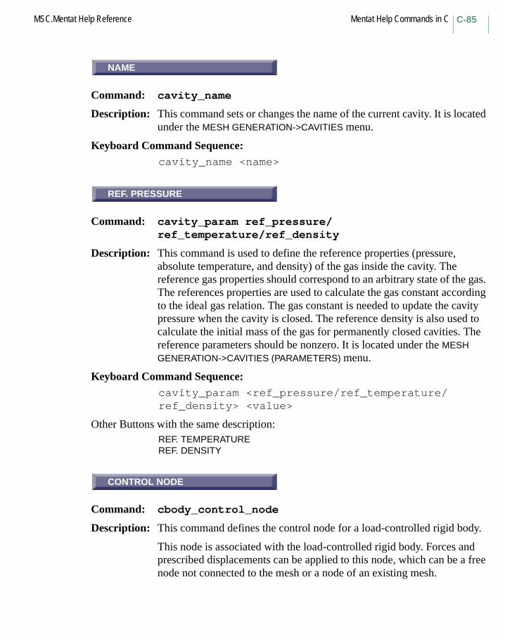
C-85MSC.Mentat Help Reference Mentat Help Commands in C
NAME
Command: cavity_name
Description: This command sets or changes the name of the current cavity. It is located under the MESH GENERATION->CAVITIES menu.
Keyboard Command Sequence: cavity_name <name>
REF. PRESSURE
Command: cavity_param ref_pressure/ref_temperature/ref_density
Description: This command is used to define the reference properties (pressure, absolute temperature, and density) of the gas inside the cavity. The reference gas properties should correspond to an arbitrary state of the gas. The references properties are used to calculate the gas constant according to the ideal gas relation. The gas constant is needed to update the cavity pressure when the cavity is closed. The reference density is also used to calculate the initial mass of the gas for permanently closed cavities. The reference parameters should be nonzero. It is located under the MESH GENERATION->CAVITIES (PARAMETERS) menu.
Keyboard Command Sequence: cavity_param <ref_pressure/ref_temperature/ref_density> <value>
Other Buttons with the same description:REF. TEMPERATUREREF. DENSITY
CONTROL NODE
Command: cbody_control_node
Description: This command defines the control node for a load-controlled rigid body.
This node is associated with the load-controlled rigid body. Forces and prescribed displacements can be applied to this node, which can be a free node not connected to the mesh or a node of an existing mesh.
NAME
REF. PRESSURE
CONTROL NODE
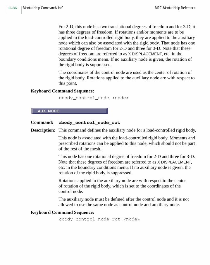
Mentat Help Commands in C MSC.Mentat Help ReferenceC-86
For 2-D, this node has two translational degrees of freedom and for 3-D, it has three degrees of freedom. If rotations and/or moments are to be applied to the load-controlled rigid body, they are applied to the auxiliary node which can also be associated with the rigid body. That node has one rotational degree of freedom for 2-D and three for 3-D. Note that these degrees of freedom are referred to as X DISPLACEMENT, etc. in the boundary conditions menu. If no auxiliary node is given, the rotation of the rigid body is suppressed.
The coordinates of the control node are used as the center of rotation of the rigid body. Rotations applied to the auxiliary node are with respect to this point.
Keyboard Command Sequence: cbody_control_node <node>
AUX. NODE
Command: cbody_control_node_rot
Description: This command defines the auxiliary node for a load-controlled rigid body.
This node is associated with the load-controlled rigid body. Moments and prescribed rotations can be applied to this node, which should not be part of the rest of the mesh.
This node has one rotational degree of freedom for 2-D and three for 3-D. Note that these degrees of freedom are referred to as X DISPLACEMENT, etc. in the boundary conditions menu. If no auxiliary node is given, the rotation of the rigid body is suppressed.
Rotations applied to the auxiliary node are with respect to the center of rotation of the rigid body, which is set to the coordinates of the control node.
The auxiliary node must be defined after the control node and it is not allowed to use the same node as control node and auxiliary node.
Keyboard Command Sequence: cbody_control_node_rot <node>
AUX. NODE

C-87MSC.Mentat Help Reference Mentat Help Commands in C
RESET
Command: cbody_reset
Description: This command resets all contact body parameters and options to their default values.
Keyboard Command Sequence: cbody_reset
TABLE
Command: cbody_table
Description: This command selects a table to be applied to a property of a contact body. You must specify a slot name and a previously defined table by name. Slot names are specified by a property name appended with a slot number (e.g. x0).
A table is a function of one variable, i.e. y = f(x), that is applied to the corresponding contact body property value. The table is commonly a function of a variable such as time, frequency, temperature, or position. These tables are used by the analysis program to define the spatial or temporal variation of a quantity.
Keyboard Command Sequence:
cbody_table <property name><slot number><table name>
CHANGE CLASS
Menu: CHANGE CLASS
Description: This menu contains commands for changing the class of elements.
Note that when you change the class of an element, any boundary conditions that are specified on the element will be transferred to the new element(s). The attach information of the edges and faces and the set membership of the element will be transferred as well.
RESET
TABLE
CHANGE CLASS

Mentat Help Commands in C MSC.Mentat Help ReferenceC-88
CURRENT DIRECTORY
Command: change_directory
Description: This command allows you to change the program’s current directory. The current directory is initially the directory from which MSC.Marc Mentat was started. Relative path and file names specified to MSC.Marc Mentat begin at the current directory.
Keyboard Command Sequence: change_directory <directory path>
ELEMENTS
Command: change_elements
Description: This command redefines the class of existing elements. You must specify a list of elements.
This command is usually used to transform from lower order (linear) to higher order (quadratic) elements and vice versa. After performing such an operation, it is recommended that the sweep command be executed.
Keyboard Command Sequence: change_elements <element list> #
ELEMENTS
Command: change_elements_class
Description: This command replaces existing elements with new elements of a given class. You must specify a list of elements.
The command is usually used to transform from lower-order (linear) to higher-order (quadratic) elements and vice versa. For those conversions that require the creation of new nodes (such as the conversion from lower order to higher order elements), the command creates unique midside nodes that are shared by coinciding edges and faces of neighboring elements. No subsequent sweep command is required.
Keyboard Command Sequence:
change_elements_class <element list> #
CURRENT DIRECTORY
ELEMENTS
ELEMENTS

C-89MSC.Mentat Help Reference Mentat Help Commands in C
TO LINEAR ELEMENTS
Command: change_elements_linear
Description: This command replaces existing higher-order elements with new lower-order elements. You must specify a list of elements.
The midside nodes of the original elements will be removed. No subsequent sweep command is required.
Keyboard Command Sequence:
change_elements_linear <element list> #
TO QUADRATIC ELEMENTS
Command: change_elements_quadratic
Description: This command replaces existing higher-order elements with new lower-order elements. You must specify a list of elements.
The command creates unique midside nodes that are shared by coinciding edges and faces of neighboring elements. No subsequent sweep command is required.
Keyboard Command Sequence:
change_elements_quadratic <element list> #
ASPECT RATIO
Command: check_aspect
Description: This command checks every element in the mesh for aspect ratio. Aspect ratio is defined as the ratio of perimeter to the area of 2-D elements and total surface area to the volume in the case of 3-D elements, normalized with respect to corresponding elements of unit size. Equilateral triangles, squares, cubes etc., have a perfect aspect ratio of 1.0. Deviations from these perfect shapes result in higher aspect ratios. Upon completion of this command, all elements having aspect ratios higher than the set threshold + 1.0 are selected.
Keyboard Command Sequence: check_aspect
TO LINEAR ELEMENTS
TO QUADRATIC ELEMENTS
ASPECT RATIO
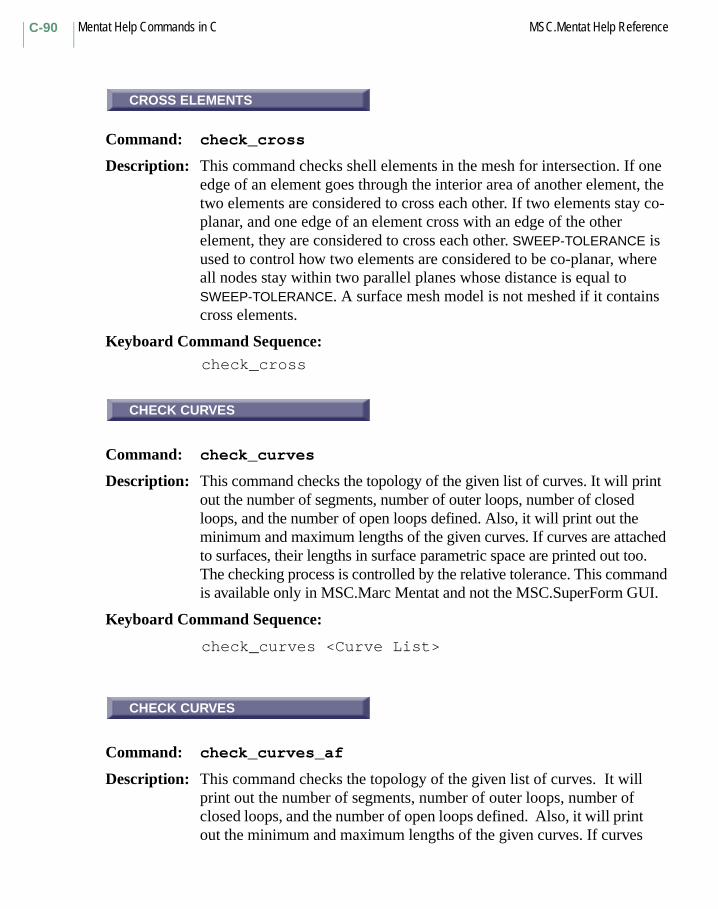
Mentat Help Commands in C MSC.Mentat Help ReferenceC-90
CROSS ELEMENTS
Command: check_cross
Description: This command checks shell elements in the mesh for intersection. If one edge of an element goes through the interior area of another element, the two elements are considered to cross each other. If two elements stay co-planar, and one edge of an element cross with an edge of the other element, they are considered to cross each other. SWEEP-TOLERANCE is used to control how two elements are considered to be co-planar, where all nodes stay within two parallel planes whose distance is equal to SWEEP-TOLERANCE. A surface mesh model is not meshed if it contains cross elements.
Keyboard Command Sequence: check_cross
CHECK CURVES
Command: check_curves
Description: This command checks the topology of the given list of curves. It will print out the number of segments, number of outer loops, number of closed loops, and the number of open loops defined. Also, it will print out the minimum and maximum lengths of the given curves. If curves are attached to surfaces, their lengths in surface parametric space are printed out too. The checking process is controlled by the relative tolerance. This command is available only in MSC.Marc Mentat and not the MSC.SuperForm GUI.
Keyboard Command Sequence:
check_curves <Curve List>
CHECK CURVES
Command: check_curves_af
Description: This command checks the topology of the given list of curves. It will print out the number of segments, number of outer loops, number of closed loops, and the number of open loops defined. Also, it will print out the minimum and maximum lengths of the given curves. If curves
CROSS ELEMENTS
CHECK CURVES
CHECK CURVES

C-91MSC.Mentat Help Reference Mentat Help Commands in C
are attached to surfaces, their lengths in surface parametric space are printed out too. This command is available only in the MSC.SuperForm GUI and not in MSC.Marc Mentat.
Keyboard Command Sequence:
check_curves_af <Curve List>
DISTORTED
Command: check_distorted
Description: This command checks every element in the mesh for shape distortion. Elements with distortion value greater than user specified threshold value under THRESHOLD are identified as distorted. Upon completion of this command, all distorted elements are selected.
Keyboard Command Sequence:
check_distorted
Another Button with the same description:
THRESHOLD
wCHECK
Menu: CHECK
Description: This menu contains commands for checking the integrity of the model. There are commands for checking for distorted, upside-down, or inside-out elements, and commands for reversing the orientation of elements, curves, and surfaces.
Another Button with the same description:
CHECK MESH
DISTORTED
CHECK

Mentat Help Commands in C MSC.Mentat Help ReferenceC-92
INSIDE OUT
Command: check_inside_out
Description: This command checks every solid element for negative Jacobian. This usually results from an incorrect element connectivity caused by EXPAND or SYMMETRY commands. Upon completion of this command, all inside out elements are selected. Inside-out elements can be repaired with the flip_elements command.
Keyboard Command Sequence: check_inside_out
CHECK
Command: check_job
Description: This command checks the validity and completeness of the current job. Also, it will assign automatically the appropriate MSC.Marc element types for each element if possible.
Keyboard Command Sequence: check_job
CHECK EDGES
Command: check_solid_edges
Description: Traversed the selected edges and checked for problems. If there is a problem, it is printed to the message area. Here are the checks performed by the program:
• self-intersecting,• is twisted,• has too much oscillation,• has regenerate edges, or• is not G0, G1, or G2.
Keyboard Command Sequence:
check_solid_edges <edge list> #
INSIDE OUT
CHECK
CHECK EDGES
C-93MSC.Mentat Help Reference Mentat Help Commands in C
CHECK ENTITIES
Command: check_solid_entities
Description: Traversed the selected entities and checked for problems. If there is a problem, it is printed to the message area. Here are the checks performed by the program.
Data Structure Checks:- The parent has appropriate child-level entity; e.g. body has lump.
- Presence (non-NULL) and closure of backptr from child to parent; e.g. body slump points to body.
- The coedge on spline surface has PCURVE.
- PCURVE indexing (0/+-1/+-2) is appropriate.
- The PCURVE has non-NULL bs2_curve. The form of the PCURVE agrees with the form of the CURVE.
Topological Checks:- LOOPS must be closed in both the next and prev directions.
- Coedges around a vertex form a circular double-linked list through alternate next/previous pointers and all share the same vertex.
- Coedges have partners whose partners are themselves.
- Partner coedges share (point to) the same edge and have opposite senses.
Geometric Checks:- The vertex point lies in the face and on the edge curve.
- The face normal is consistent with coedge direction.
- The PCURVE start/end parameters match those of coedge.
- The PCURVE start/end location (wrt surf parameters) must equal coedge’s start/end location.
- Entities with geometry must have non-NULL geometry; e.g. FACE points to SURFACE and EDGE has CURVE, etc.
Keyboard Command Sequence:
check_solid_entities <entities list> #
Another Button with the same description:
CHECK LOG
CHECK ENTITIES

Mentat Help Commands in C MSC.Mentat Help ReferenceC-94
CHECK FACES
Command: check_solid_faces
Description: Traversed the selected faces and checked for problems. If there is a problem, it is printed to the message area. Here are the checks performed by the program:
• self-intersecting,• is twisted,• has too much oscillation,• has egenerate edges, or• is not G0, G1, or G2.
Keyboard Command Sequence:check_solid_faces <face list> #
CHECK SURFACES
Command: check_surfaces
Description: This command checks the topology of the curves trimming each surface in the given list. For each surface, it will print out the number of segments, number of outer loops, number of closed loops, and the number of open loops defined. Also, it will print out the minimum and maximum trimming curve lengths for the given surfaces. The checking process is controlled by the relative tolerance.
Keyboard Command Sequence: check_surfaces <Surface List>
CHECK SURFACES
Command: check_surfaces_af
Description: This command checks the topology of the curves trimming each surface in the given list. For each surface, it will print out the number of segments, number of outer loops, number of closed loops, and the number of open loops defined. Also, it will print out the minimum and maximum trimming curve lengths for the given surfaces.
Keyboard Command Sequence: check_surfaces_af <Surface List>
CHECK FACES
CHECK SURFACES
CHECK SURFACES

C-95MSC.Mentat Help Reference Mentat Help Commands in C
UPSIDE DOWN
Command: check_upside_down
Description: This command checks all two-dimensional elements (including shells) for negative Jacobian. This usually results from an incorrect connectivity caused by EXPAND or SYMMETRY commands. Upon completion of this command, all upside-down elements are selected. Upside-down elements can be repaired with the flip_elements command.
Keyboard Command Sequence: check_upside_down
ZERO VOLUME
Command: check_zero
Description: This command checks every element in the mesh for zero volume. Upon completion of this command, all elements which have zero volume are selected.
Keyboard Command Sequence:
copy_insert
CLEAN 2D CURVE LOOPS
Command: clean_2d_loops
This command removes curves whose lengths are smaller than the tolerance and merges points together when the distance between them is shorter than the tolerance. The tolerance value is computed by multiplying the relative tolerance value by the curve length.
Also see: set_relative_tol and clean_surface_loops.
Keyboard Command Sequence:
clean_2d_loops <curve list>
UPSIDE DOWN
ZERO VOLUME
CLEAN 2D CURVE LOOPS

Mentat Help Commands in C MSC.Mentat Help ReferenceC-96
CLEAN 2D CURVE LOOPS
Command: clean_2d_loops_af
This command removes curves whose lengths are shorter than the minimum tolerance and merges points together when the distance between them is shorter than the minimum tolerance.
Also see: set_mesh_min_tol and clean_surface_loops.
Keyboard Command Sequence: clean_2d_loops_af <curve list>
CLEAN
Command: clean_animation
Description: This command removes the temporary animation display lists which are created with the commands:
or those that are created after you have performed the steps for MPEG MOVIE or AVI MOVIE.
The files that are removed are those named <base name>nnn, where <base name> is the name specified with the animation_name command (BASE FILE button). It defaults to animation. The nnn is a numbered sequence from 1 to 1000, unless LAST (movie_last_increment command) is larger, in which case it is used.
You would typically run this command after you have run movie_animation_make (MAKE MOVIE button) or avi_animation_make (MAKE AVI MOVIE button).
Also see help: clean_mpeg_animation.
Keyboard Command Sequence:clean_animation
animation_save ANIMATION->CREATE->SINGLE FRAME
post_animate_increments ANIMATION->CREATE->INCREMENTS
post_animate_mode ANIMATION->CREATE->MODE
post_animate_harmonic ANIMATION->CREATE->HARMONICS
CLEAN 2D CURVE LOOPS
CLEAN
C-97MSC.Mentat Help Reference Mentat Help Commands in C
CLEAN
Command: clean_mpeg_animation
Description: This command removes the temporary animation display lists which are created when the command mpeg_animation_make (MAKE MPEG MOVIE button).
The files that are removed are those named <base name>nnn, where <base name> is the name specified with the animation_name command (BASE FILE button). It defaults to animation. The nnn is a numbered sequence from 1 to 1000, unless LAST (movie_last_increment command) is larger, in which case it is used.
The files named <base name>nnn.ppm are also removed.
You would typically run this command after you have successfully run the command mpeg_animation_make (MAKE MPEG MOVIE button) and have obtained a valid .mpeg file.
Notes: The MPEG movie is created in the background by running the mpeg_encode.exe program. It does NOT send any feedback to Mentat that it is done. You must verify that the mpeg_encode.exe program is no longer running to be sure that it has finished before running this command, otherwise you will have deleted the .ppm files that the MPEG encoder needs.
Use the Windows Task Manager on NT or use the ps command on UNIX to verify that the program has ended.
Also see help: clean_animation.
Keyboard Command Sequence:
clean_mpeg_animation
CLEAN ENTITIES
Command: clean_solid_entities
Description: Removes all unnecessary and/or redundant edges (faces and associated data) and vertices from the entity. An edge is not needed if the surface defining the two faces of the edge are the same geometrically.
Keyboard Command Sequence:clean_solid_entities <entities list> #
CLEAN
CLEAN ENTITIES
Mentat Help Commands in C MSC.Mentat Help ReferenceC-98
CLEAN SURFACE LOOPS
Command: clean_surface_loops
Description: This command performs several functions to clean surface geometry for surface meshing. It hooks the trimming curves into loops on the base of the distances between the end points of curves. In addition, it also matches the neighboring trimming curves.
Four options are provided to control the cleaning process. They are Trim Bare Surfaces, Remove Free Curves, Break Curves, and Match Curves.
This process is implemented based on the tolerance. The tolerance parameter can be specified under OPTION menu. This tolerance parameter is used as a relative coefficient. The absolute tolerance is computed by multiplying this user specified value by the curve length.
Also see: set_trim_surfs, set_rm_free_crvs, set_break_crvs, set_match_crvs, and set_relative_tol.
Keyboard Command Sequence:
clean_surface_loops <surface list>
CLEAN SURFACE LOOPS
Command: clean_surface_loops_af
Description: This command performs several functions to clean surface geometry for surface meshing. It hooks the trimming curves into loops on the base of the distances between the end points of curves. In addition, it also matches the neighboring trimming curves.
Four options are provided to control the cleaning process. They are Trim Bare Surfaces, Remove Free Curves, Break Curves, and Match Curves.
This process is implemented based on the tolerance. The tolerance parameter can be specified under OPTION menu. This tolerance parameter is used as a relative coefficient. The absolute tolerance is computed by multiplying this user specified value by the curve length.
CLEAN SURFACE LOOPS
CLEAN SURFACE LOOPS
C-99MSC.Mentat Help Reference Mentat Help Commands in C
Also see: set_trim_surfs, set_rm_free_crvs, set_break_crvs, set_match_crvs, and set_relative_tol.
Keyboard Command Sequence: clean_surface_loops_af <surface list>
CLEAR
Command: clear_annotations
Description: This command removes all annotations. This button is located in the UTITLITIES->MORE menu.
Keyboard Command Sequence: clear_annotations
apply1
Command: apply_dofclear_apply_dof
Description: These commands add and clear the specified degree of freedom from the current boundary condition application. The button text will be the name of the boundary condition.
Keyboard Command Sequence: apply_dof <dof name>clear_apply_dof <dof name>
CLEAR
Command: clear_csect_control_node
Description: This command removes the previously selected control node of the current cross-section. This button is located in the BOUNDARY CONDITION->MECHANICAL->CROSS SECTIONS menu.
Keyboard Command Sequence: clear_csect_control_node
CLEAR
apply1
CLEAR

Mentat Help Commands in C MSC.Mentat Help ReferenceC-100
CLEAR
Command: clear_current_apply
Description: This command clears all degrees of freedom, values, and table specifications from the current boundary condition. This button is located in the BOUNDARY CONDITIONS->MECHANICAL->FIXED DISPLACEMENT and other boundary conditions menus.
Keyboard Command Sequence:
clear_current_apply
CLEAR
Command: clear_current_icond
Description: This command clears all degrees of freedom, values, and table specifications from the current initial condition. This button is located in the INITIAL CONDITIONS->MECHANICAL->DISPLACEMENT and other initial conditions menus.
Keyboard Command Sequence:
clear_current_icond
CLEAR CURVE DIVISIONS
Command: clear_curve_divisions
Description: This command removes previously applied automatic meshing curve divisions. Curve divisions are used as boundary element edges in automatic meshing. Curves which no divisions are specified will be meshed with a default of three divisions for closed curves, and one division for open curves.
Keyboard Command Sequence:
clear_curve_divisions <curve list>
CLEAR
CLEAR
CLEAR CURVE DIVISIONS

C-101MSC.Mentat Help Reference Mentat Help Commands in C
CLEAR
Command: clear_element_type
Description: This command clears the MSC.Marc element type for the specified elements. If a job is submitted to MSC.Marc with elements with no assigned type, MSC.Marc Mentat will assign an appropriate type based on element geometry and analysis type. MSC.Marc element types may be assigned to elements with the element_type command. This button is located in the JOBS->ELEMENT TYPES menu.
Keyboard Command Sequence: clear_element_type <element list> #
CLEAR GEOM
Command: clear_geometry
Description: This command deletes all existing points, curves, and surfaces. By using clear_geometry and clear_mesh together, the entire display can be cleared of its graphical components. This button is located in the MESH GENERATION menu.
Keyboard Command Sequence:
clear_geometry
CLEAR
Command: clear_geometry_values
Description: This command clears all property values for the current geometry. This button is located in the JOBS->ELEMENT TYPES menu.
Keyboard Command Sequence:
clear_geometry_values
CLEAR
CLEAR GEOM
CLEAR

Mentat Help Commands in C MSC.Mentat Help ReferenceC-102
clear_icond_dof
Command: icond_dofclear_icond_dof
Description: These commands add and clear the specified degree of freedom from the current initial condition. The button text will be the name of the initial condition. This button is located in the INITIAL CONDITIONS-> MECHANICAL->DISPLACEMENT and other initial conditions menus.
Keyboard Command Sequence:
icond_dof <dof name>clear_icond_dof <dof name>
CLEAR
Command: clear_icond_layers
Description: This command clears element layers for the current state variable initial condition.
Keyboard Command Sequence:
clear_icond_layers
CLEAR
Command: clear_ideas_elem_vars
Description: This command clears the current job’s list of I-DEAS element results variables. This button is located in the JOBS->MECHANICAL->JOB RESULTS->I-DEAS other analysis class menus.
Keyboard Command Sequence:
clear_ideas_elem_vars
clear_icond_dof
CLEAR
CLEAR

C-103MSC.Mentat Help Reference Mentat Help Commands in C
INCREMENTS
Command: clear_job_buckle_increments
Description: This command clears increments from the current job’s buckle analysis parameters.
Keyboard Command Sequence:
clear_job_buckle_increments
CLEAR
Command: clear_job_careas
Description: This command removes all contact areas from the current job. This button is located in the JOBS->MECHANICAL->CONTACT CONTROL-> INITIAL CONTACT other analysis class menus.
Keyboard Command Sequence:
clear_job_careas
CLEAR
Command: clear_job_ctable
Description: This command removes the initial contact table from the current job. This button is located in the JOBS->MECHANICAL->CONTACT CONTROL-> CONTACT TABLE and other analysis class menus.
Keyboard Command Sequence:
clear_job_ctable
INCREMENTS
CLEAR
CLEAR

Mentat Help Commands in C MSC.Mentat Help ReferenceC-104
ChaptCLEAR
Command: clear_job_exsegs
Description: This command removes all exclude segments from the current job. This button is located in the JOBS->MECHANICAL->CONTACT CONTROL-> INITIAL CONTACT and other analysis class menus.
Keyboard Command Sequence:
clear_job_exsegs
CLEAR
Command: clear_job_iconds
Description: This command clears all initial conditions from the current job. This button is located in the JOBS->MECHANICAL->INITIAL LOADS and other analysis class menus.
Keyboard Command Sequence:
clear_job_iconds
CLEAR
Command: clear_job_loadcases
Description: This command removes all loadcases from the current job. This button is located in the JOBS->MECHANICAL and other analysis class menus.
Keyboard Command Sequence:
clear_job_loadcases
CLEAR
CLEAR
CLEAR

C-105MSC.Mentat Help Reference Mentat Help Commands in C
CLEAR
Command: clear_job_modal_increments
Description: This command clears increments from the current job’s modal analysis parameters. This button is located in the JOBS->MECHANICAL-> ANALYSIS OPTIONS->BUCKLE INCREMENTS menu.
Keyboard Command Sequence:
clear_job_modal_increments
CLEAR LAYERS
Command: clear_layered_material
Description: This command removes material layers from a layered material. The command will remove all layers from the first layer specified to the last layer specified.
Keyboard Command Sequence:
clear_layered_material <from layer number><to layer number>
CLEAR
Command: clear_loadcase_careas
Description: This command removes all contact areas from the current loadcase. This button is located in the LOADCASES->MECHANICAL->STATIC->CONTACT other loadcase type menus.
Keyboard Command Sequence:
clear_loadcase_careas
CLEAR
CLEAR LAYERS
CLEAR

Mentat Help Commands in C MSC.Mentat Help ReferenceC-106
CLEAR
Command: clear_loadcase_cbodies
Description: This command removes all contact body releases from the current loadcase. This button is located in the LOADCASES->MECHANICAL-> STATIC->CONTACT other loadcase type menus.
Keyboard Command Sequence:
clear_loadcase_cbodies
CLEAR
Command: clear_loadcase_ctable
Description: This command clears the contact table from the current loadcase. This button is located in the LOADCASES->MECHANICAL->STATIC-> CONTACT->CONTACT TABLE other loadcase type menus.
Keyboard Command Sequence:
clear_loadcase_ctable
CLEAR
Command: clear_loadcase_exsegs
Description: This command removes all exclude segments from the current loadcase. This button is located in the LOADCASES->MECHANICAL->STATIC-> CONTACT other loadcase type menus.
Keyboard Command Sequence:
clear_loadcase_exsegs
CLEAR
CLEAR
CLEAR

C-107MSC.Mentat Help Reference Mentat Help Commands in C
CLEAR
Command: clear_loadcase_loads
Description: This command clears all boundary condition (loads) from the current loadcase. This button is located in the LOADCASES->MECHANICAL-> STATIC->LOADS other loadcase class menus.
Keyboard Command Sequence:
clear_loadcase_loads
CLEAR
Command: clear_material_table
Description: This command clears a table for a property in the current material.
The property that the table is to be removed from is designated by the material type and the property name is separated by a colon and appended with a table number.For example, a table for Young’s modulus in anisotropic material is designated as isotropic:e0. Table numbers start at zero.
Note that only certain properties may have tables associated with them. Refer to Marc material model descriptions to determine which properties can have tables.
Keyboard Command Sequence:
clear_material_table <material type>:<property name> <table number>
CLEAR
CLEAR

Mentat Help Commands in C MSC.Mentat Help ReferenceC-108
CLEAR
Command: clear_mesh
Description: This command deletes all nodes and element from the current model. It deletes the entire mesh, leaving the original geometry intact, so that the mesh can be regenerated. By using CLEAR MESH and CLEAR GEOMETRY together, the entire display can be cleared of its graphical components. This button is located in the MESH GENERATION menu.
Keyboard Command Sequence:
clear_mesh
Another Button with the same description:
CLEAR MESH
clear_post_tensors
Command: clear_post_tensors
Description: This command clears the current job’s list of results tensors. This command is only available in the SuperForm GUI.
Keyboard Command Sequence:
clear_post_tensors
CLEAR
Command: clear_post_vars
Description: This command clears the current job’s list of results variables. This command is only available in the SuperForm GUI.
clear_post_vars
CLEAR
clear_post_tensors
CLEAR
C-109MSC.Mentat Help Reference Mentat Help Commands in C
CLOSE
Command: close_procedure
Description: This command terminates the recording of commands in the procedure file and closes the file.
Keyboard Command Sequence: close_procedure
BACKGROUND
Command: color
Description: This command changes the color the program uses for a particular index. The indices range from zero to 95. Each color index is used when drawing a particular item on the screen or to a color plotter. For instance, the text in the dialogue area of the program uses color index 1. You must specify the color index to change and the new red, green, or blue values for the new color. These values range from zero to one, where zero means completely off, and one means completely on.
After using this command to change the color at an index, the lighting material properties of the index are automatically changed to look like plastic of the given color. Thus when lighting is on, or when rendering, items using the color index will look like they’re made of plastic.
Also see: color_hls and reset_colors.
Keyboard Command Sequence: color <color index> <red> <green> <blue>
Other Buttons with the same description:
0 through 95ACTIVE WINDOW BORDERSANNOTATIONSARROW EDGESBACKFACESBOUNDARY CONDITIONSCONTOUR LINE BACKGROUNDCONTOUR LOWER BOUNDCONTOUR UPPER BOUNDCURVES
CLOSE
BACKGROUND
Mentat Help Commands in C MSC.Mentat Help ReferenceC-110
ELEMENT EDGESELEMENT FACESELEMENTS UNDEFORMEDFACE CUTFLOW LINESGRAPH FILLGRAPHSGRID BODYGRID DIVISIONSHIGHLIGHTED ENTITIESIDENTIFY 1 through IDENTIFY 16IDENTIFY NONENODESPOINTSPOST PROCESSING TEXTSELECTED EDGESSELECTED ENTITIESSELECTED FACESSURFACE FILLSURFACE LINESURFACE WIRETRIAD EDGESTRIAD XTRIAD YTRIAD Z
color_ambient
Command: color_ambient
Description: This command changes the ambient lighting material property the program uses for a particular index. Each color index is used when drawing a particular item on the screen or to a color plotter. The ambient color of an item interacts with the ambient light in a view when lighting is on, or when rendering. Ambient light is nondirectional, and contributes to the overall light in a view. The indices range from zero to 95. You must specify the color index to change and the new red, green, or blue values for the ambient color. These values range from zero to one, where zero means completely off, and one means completely on.
Also see: color, set_lighting, and render.
Keyboard Command Sequence:
color_ambient <color index> <red> <green> <blue>
color_ambient

C-111MSC.Mentat Help Reference Mentat Help Commands in C
ATTEN. LENGTH
Command: color_atten_len
Description: This command changes the attenuation length lighting material property the program uses for a particular index. Each color index is used when drawing a particular item on the screen or to a color plotter. The attenuation length of a solid item is used when rendering. White light traveling through a transparent solid becomes the attenuation color of the solid after traveling through it for a distance equal to the attenuation length of the solid. Thus, the thicker a solid is, the more it is colored by its attenuation color. Also, the smaller the attenuation length of the solid, the more colored it will be by its attenuation color. A solid is made transparent by setting its refractive color to 1, 1, 1. The indices range from zero to 95. You must specify the color index to change and the new attenuation length in view space.
Also see: color, color_attenuation, color_refractive, set_lighting, and render.
Keyboard Command Sequence:
color_atten_len <color index> <length>
color_attenuation
Command: color_attenuation
Description: This command changes the attenuation lighting material property the program uses for a particular index. Each color index is used when drawing a particular item on the screen or to a color plotter. The attenuation color of a solid item is applied when rendering. White light traveling through a transparent solid becomes the attenuation color of the solid after traveling through it for a distance equal to the attenuation length of the solid. Thus, the thicker a solid is, the more it is colored by its attenuation color. A solid is made transparent by setting its refractive color to 1, 1, 1. The indices range from zero to 95. You must specify the color index to change and the new red, green, or blue values for the attenuation color. These values range from zero to one, where zero means completely off, and one means completely on.
ATTEN. LENGTH
color_attenuation
Mentat Help Commands in C MSC.Mentat Help ReferenceC-112
Also see: color, atten_len, color_refractive, set_lighting, and render.
Keyboard Command Sequence:
color_attenuation <color index> <red> <green> <blue>
BRASS
Command: color_brass
Description: This command makes items drawn with a given color index look like brass. The color and lighting material properties the program uses for the particular color index are set to create the appearance of brass. The full brass-like appearance of the item will be visible when lighting is on, or when rendering. A color index is used when drawing a particular item on the screen. You must specify the color index to change. The indices range from zero to 95.
Also see: color, set_lighting, and render.
Keyboard Command Sequence:
color_brass <color index>
BRONZE
Command: color_bronze
Description: This command makes items drawn with a given color index look like bronze. The color and lighting material properties the program uses for the particular color index are set to create the appearance of bronze. The full bronze-like appearance of the item will be visible when lighting is on, or when rendering. A color index is used when drawing a particular item on the screen. You must specify the color index to change. The indices range from zero to 95.
Also see: color, set_lighting, and render.
Keyboard Command Sequence:
color_bronze <color index>
BRASS
BRONZE
C-113MSC.Mentat Help Reference Mentat Help Commands in C
CHROME
Command: color_chrome
Description: This command makes items drawn with a given color index look like chrome. The color and lighting material properties the program uses for the particular color index are set to create the appearance of chrome. The full chrome-like appearance of the item will be visible when lighting is on, or when rendering. A color index is used when drawing a particular item on the screen. You must specify the color index to change. The indices range from zero to 95.
Also see: color, set_lighting, and render.
Keyboard Command Sequence:
color_chrome <color index>
COPPER
Command: color_copper
Description: This command makes items drawn with a given color index look like copper. The color and lighting material properties the program uses for the particular color index are set to create the appearance of copper. The full copper-like appearance of the item will be visible when lighting is on, or when rendering. A color index is used when drawing a particular item on the screen. You must specify the color index to change. The indices range from zero to 95.
Also see: color, set_lighting, and render.
Keyboard Command Sequence:
color_copper <color index>
CHROME
COPPER

Mentat Help Commands in C MSC.Mentat Help ReferenceC-114
DIAMOND
Command: color_diamond
Description: This command makes items drawn with a given color index look like diamond. The color and lighting material properties the program uses for the particular color index are set to create the appearance of diamond. The full diamond-like appearance of the item will be visible when rendering. A color index is used when drawing a particular item on the screen. You must specify the color index to change. The indices range from zero to 95.
Also see: color, set_lighting, and render.
Keyboard Command Sequence:
color_diamond <color index>
DIAMONDIZE
Command: color_diamondize
Description: This command makes items drawn with a given color index look like a colored diamond. The basic color already at a particular color index is used to set the lighting material properties for that index to create the appearance of a colored diamond. The full diamond-like appearance of the item will be visible when rendering. A color index is used when drawing a particular item on the screen. You must specify the color index to change. The indices range from zero to 95.
Also see: color, color_diamond, set_lighting, and render.
Keyboard Command Sequence:
color_diamondize <color index>
DIAMOND
DIAMONDIZE
C-115MSC.Mentat Help Reference Mentat Help Commands in C
color_diffuse
Command: color_diffuse
Description: This command changes the diffuse lighting material property the program uses for a particular index. Each color index is used when drawing a particular item on the screen or to a color plotter. The diffuse color of an item is its regular, dull, or matte color seen when lighting is on, or when rendering. This is the color of an item that becomes more intense as the angle of the light falling on the item approaches that of the items surface normal. The indices range from zero to 95. You must specify the color index to change and the new red, green, or blue values for the diffuse color. These values range from zero to one, where zero means completely off, and one means completely on.
Also see: color, color_specular, set_lighting, and render.
Keyboard Command Sequence:
color_diffuse <color index> <red> <green> <blue>
color_emission
Command: color_emission
Description: This command changes the emission lighting material property the program uses for a particular index. Each color index is used when drawing a particular item on the screen or to a color plotter. The emission color of an item is the color of the light emitted by the item when lighting is on, or when rendering. The indices range from zero to 95. You must specify the color index to change and the new red, green, or blue values for the emission color. These values range from zero to one, where zero means completely off, and one means completely on.
Also see: color, set_lighting, and render.
Keyboard Command Sequence:
color_emission <color index> <red> <green> <blue>
color_diffuse
color_emission

Mentat Help Commands in C MSC.Mentat Help ReferenceC-116
FROSTED GLASS
Command: color_frosted_glass
Description: This command makes items drawn with a given color index look like frosted glass. The color and lighting material properties the program uses for the particular color index are set to create the appearance of frosted glass. The full frosted glass-like appearance of the item will be visible when rendering. A color index is used when drawing a particular item on the screen. You must specify the color index to change. The indices range from zero to 95.
Also see: color, set_lighting, and render.
Keyboard Command Sequence:
color_frosted_glass <color index>
FROSTED GLASSIZE
Command: color_frosted_glassize
Description: This command makes items drawn with a given color index look like colored frosted glass. The basic color already at a particular color index is used to set the lighting material properties for that index to create the appearance of colored frosted glass. The full frosted glass-like appearance of the item will be visible when rendering. A color index is used when drawing a particular item on the screen. You must specify the color index to change. The indices range from zero to 95.
Also see: color, color_frosted_glass, set_lighting, and render.
Keyboard Command Sequence:
color_frosted_glassize <color index>
FROSTED GLASS
FROSTED GLASSIZE

C-117MSC.Mentat Help Reference Mentat Help Commands in C
GHOST
Command: color_ghost
Description: This command makes items drawn with a given color index look like ghost. The color and lighting material properties the program uses for the particular color index are set to create a translucent appearance that darkens with thickness, and which does not bend refracted light. The full ghost-like appearance of the item will be visible when rendering. A color index is used when drawing a particular item on the screen. You must specify the color index to change. The indices range from zero to 95.
Also see: color, set_lighting, and render.
Keyboard Command Sequence:
color_ghost <color index>
GHOSTIZE
Command: color_ghostize
Description: This command makes items drawn with a given color index look like colored ghost. The basic color already at a particular color index is used to set the lighting material properties for that index to create a colored translucent appearance that darkens with thickness, and which does not bend refracted light. The full ghost-like appearance of the item will be visible when rendering. A color index is used when drawing a particular item on the screen. You must specify the color index to change. The indices range from zero to 95.
Also see: color, color_ghost, set_lighting, and render.
Keyboard Command Sequence:
color_ghostize <color index>
GHOST
GHOSTIZE

Mentat Help Commands in C MSC.Mentat Help ReferenceC-118
GLASS
Command: color_glass
Description: This command makes items drawn with a given color index look like glass. The color and lighting material properties the program uses for the particular color index are set to create the appearance of glass. The full glass-like appearance of the item will be visible when rendering. A color index is used when drawing a particular item on the screen. You must specify the color index to change. The indices range from zero to 95.
Also see: color, set_lighting, and render.
Keyboard Command Sequence:
color_glass <color index>
GLASSIZE
Command: color_glassize
Description: This command makes items drawn with a given color index look like colored glass. The basic color already at a particular color index is used to set the lighting material properties for that index to create the appearance of colored glass. The full glass-like appearance of the item will be visible when rendering. A color index is used when drawing a particular item on the screen. You must specify the color index to change. The indices range from zero to 95.
Also see: color, color_glass, set_lighting, and render.
Keyboard Command Sequence:
color_glassize <color index>
GLASS
GLASSIZE

C-119MSC.Mentat Help Reference Mentat Help Commands in C
GOLD
Command: color_gold
Description: This command makes items drawn with a given color index look like gold. The color and lighting material properties the program uses for the particular color index are set to create the appearance of gold. The full gold-like appearance of the item will be visible when lighting is on, or when rendering. A color index is used when drawing a particular item on the screen. You must specify the color index to change. The indices range from zero to 95.
Also see: color, set_lighting, and render.
Keyboard Command Sequence:
color_gold <color index>
HUE-LIGHTNESS-SATURATION
Command: color_hls
Description: This command changes the color the program uses for a particular index. The indices range from zero to 95. Each color index is used when drawing a particular item on the screen or to a color plotter. For instance, the text in the dialogue area of the program uses color index. You must specify the color index to change and the new hue, lightness, and saturation values for the new color.
The hue value ranges from zero to 360, where:
0 = blue 180 = yellow 60 = magenta 240 = green120 = red 300 = cyan
The lightness component ranges from zero to one, where zero means no lightness, and one means complete lightness. The saturation component ranges from zero to one, where zero means no saturation (gray) and one means complete saturation (vibrant color).
After using this command to change the color at an index, the lighting material properties of the index are automatically changed to look like
GOLD
HUE-LIGHTNESS-SATURATION

Mentat Help Commands in C MSC.Mentat Help ReferenceC-120
plastic of the given color. Thus when lighting is on, or when rendering, items using the color index will look like they’re made of plastic.
Also see: color and reset_colors.
Keyboard Command Sequence:
color_hls <color index> <hue> <lightness><saturation>
COLOR INDEX
Command: color_index
Description: This command sets the index of the current color table entry.
Keyboard Command Sequence:
color_index <color table index>
INDEX
Command: color_index_ref
Description: This command changes the index of refraction lighting material property the program uses for a particular color index. Each color index is used when drawing a particular item on the screen or to a color plotter. The index of refraction of an item is used when rendering. Light traveling through a transparent item will be bent by an angle determined by the index of refraction of the item. An item is made transparent by setting its refractive color to something other than black (0, 0, 0). The indices range from zero to 95. You must specify the color index to change and the new index of refraction.
Also see: color, color_refractive, color_index_ref_spread, set_lighting, and render.
Keyboard Command Sequence:
color_index_ref <color index><index of refraction>
COLOR INDEX
INDEX

C-121MSC.Mentat Help Reference Mentat Help Commands in C
SPREAD
Command: color_index_ref_spread
Description: This command changes the index of refraction spread lighting material property the program uses for a particular color index. Each color index is used when drawing a particular item on the screen or to a color plotter. The index of refraction spread of an item is used to modify the index of refraction of an item when rendering. Light traveling through a transparent item will be bent by an angle determined by the index of refraction of the item. If the spread is set to zero, then all light passing through the item will be bent by the same amount (coherently). If the spread is greater than zero, light passing through the item will be split into its separate red, green, and blue components, and each ray will be bent differently.
The red ray will be bent using an index of refraction which is one half of the spread less than the index of refraction of the item it’s passing through.
The green ray will be bent using the index of refraction of the item.
The blue ray will be bent using an index of refraction which is one half of the spread greater than the index of refraction of the item. An item is made transparent by setting its refractive color to something other than black (0, 0, 0). The indices range from zero to 95. You must specify the color index to change and the new index of refraction spread.
Also see: color, color_refractive, color_index_ref, set_lighting, and render.
Keyboard Command Sequence:
color_index_ref_spread <color index><index of refr. spread>
SPREAD
Mentat Help Commands in C MSC.Mentat Help ReferenceC-122
color_initialize
Command: color_initialize
Description: This command makes items drawn with a given color index look like black plaster. The color and lighting material properties the program uses for the particular color index are set to create a black opaque non- reflective non-shiny appearance. A color index is used when drawing a particular item on the screen. You must specify the color index to change. The indices range from zero to 95.
Also see: color, set_lighting, and render.
Keyboard Command Sequence:
color_initialize <color index>
METALIZE
Command: color_metalize
Description: This command makes items drawn with a given color index look like colored metal. The basic color already at a particular color index is used to set the lighting material properties for that index to create the appearance of colored metal. The full metal-like appearance of the item will be visible when lighting is on, or when rendering. A color index is used when drawing a particular item on the screen. You must specify the color index to change. The indices range from zero to 95.
Also see: color, set_lighting, and render.
Keyboard Command Sequence:
color_metalize <color index>
color_initialize
METALIZE

C-123MSC.Mentat Help Reference Mentat Help Commands in C
MIRROR
Command: color_mirror
Description: This command makes items drawn with a given color index look like a mirror. The color and lighting material properties the program uses for the particular color index are set to create the appearance of a mirror. The full mirror-like appearance of the item will be visible when rendering. A color index is used when drawing a particular item on the screen. You must specify the color index to change. The indices range from zero to 95.
Also see: color, set_lighting, and render.
Keyboard Command Sequence:
color_mirror <color index>
MIRRORIZE
Command: color_mirrorize
Description: This command makes items drawn with a given color index look like a colored mirror. The basic color already at a particular color index is used to set the lighting material properties for that index to create the appearance of a colored mirror. The full mirror-like appearance of the item will be visible when rendering. A color index is used when drawing a particular item on the screen. You must specify the color index to change. The indices range from zero to 95.
Also see: color, color_mirror, set_lighting, and render.
Keyboard Command Sequence:
color_mirrorize <color index>
MIRROR
MIRRORIZE
Mentat Help Commands in C MSC.Mentat Help ReferenceC-124
PLASTERIZE
Command: color_plasterize
Description: This command makes items drawn with a given color index look like colored plaster. The basic color already at a particular color index is used to set the lighting material properties for that index to create the appearance of colored plaster. The full plaster-like appearance of the item will be visible when lighting is on, or when rendering. A color index is used when drawing a particular item on the screen. You must specify the color index to change. The indices range from zero to 95.
Also see: color, set_lighting, and render.
Keyboard Command Sequence:
color_plasterize <color index>
PLASTICIZE
Command: color_plasticize
Description: This command makes items drawn with a given color index look like colored plastic. The basic color already at a particular color index is used to set the lighting material properties for that index to create the appearance of colored plastic. The full plastic-like appearance of the item will be visible when lighting is on, or when rendering. A color index is used when drawing a particular item on the screen. You must specify the color index to change. The indices range from zero to 95.
Also see: color, set_lighting, and render.
Keyboard Command Sequence:
color_plasticize <color index>
PLASTERIZE
PLASTICIZE
C-125MSC.Mentat Help Reference Mentat Help Commands in C
color_reflective
Command: color_reflective
Description: This command changes the reflective lighting material property the program uses for a particular index. Each color index is used when drawing a particular item on the screen or to a color plotter. The reflective color of an item determines how other items are reflected in the item when rendering. The indices range from zero to 95. You must specify the color index to change and the new red, green, and blue values for the reflective color. These values range from zero to one, where zero means completely off, and one means completely on.
Also see: color, color_specular, set_lighting, and render.
Keyboard Command Sequence:
color_reflective <color index> <red><green><blue>
color_refractive
Command: color_refractive
Description: This command changes the refractive lighting material property the program uses for a particular index. Each color index is used when drawing a particular item on the screen or to a color plotter. The refractive color of an item is used to make the item transparent, or opaque when rendering. If the refractive color is not black (0, 0, 0), then the item is at least partially transparent, and white light striking the item will pass through it, and become colored by the refractive color of the item. The transmitted light will also be bent by an angle determined by the index of refraction of the item. The indices range from zero to 95. You must specify the color index to change and the new red, green, and blue values for the refractive color. These values range from zero to one, where zero means completely off, and one means completely on.
Also see: color, color_index_ref, color_attenuation, set_lighting, and render.
Keyboard Command Sequence:
color_refractive <color index> <red><green><blue>
color_reflective
color_refractive

Mentat Help Commands in C MSC.Mentat Help ReferenceC-126
RUBBER
Command: color_rubber
Description: This command makes items drawn with a given color index look like rubber. The color and lighting material properties the program uses for the particular color index are set to create the appearance of rubber. The full rubber-like appearance of the item will be visible when lighting is on, or when rendering. A color index is used when drawing a particular item on the screen. You must specify the color index to change. The indices range from zero to 95.
Also see: color, set_lighting, and render.
Keyboard Command Sequence:
color_rubber <color index>
RUBBERIZE
Command: color_rubberize
Description: This command makes items drawn with a given color index look like colored rubber. The basic color already at a particular color index is used to set the lighting material properties for that index to create the appearance of colored rubber. The full rubber-like appearance of the item will be visible when lighting is on, or when rendering. A color index is used when drawing a particular item on the screen. You must specify the color index to change. The indices range from zero to 95.
Also see: color, color_rubber, set_lighting, and render.
Keyboard Command Sequence:
color_rubberize <color index>
RUBBER
RUBBERIZE
C-127MSC.Mentat Help Reference Mentat Help Commands in C
SHININESS
Command: color_shininess
Description: This command changes the shininess lighting material property the program uses for a particular color index. Each color index is used when drawing a particular item on the screen or to a color plotter. The shininess of an item is used when lighting is on, or when rendering. Shininess can range from zero to one, and determines the size of the specular highlights which appear on an item. The smaller or more focused these highlights are, the shinier the item will appear to be. A shininess of zero turns off the specular highlights completely. A shininess slightly above zero creates large highlights, while a shininess near one creates small, focused highlights. The indices range from zero to 95. You must specify the color index to change and the new shininess.
Also see: color, color_specular, set_lighting, and render.
Keyboard Command Sequence:
color_shininess <color index> <shininess>
SHINY METALIZE
Command: color_shiny_metalize
Description: This command makes items drawn with a given color index look like colored shiny metal. The basic color already at a particular color index is used to set the lighting material properties for that index to create the appearance of colored shiny metal. The full shiny metal-like appearance of the item will be visible when lighting is on, or when rendering. A color index is used when drawing a particular item on the screen. You must specify the color index to change. The indices range from zero to 95.
Also see: color, set_lighting, and render.
Keyboard Command Sequence:
color_shiny_metalize <color index>
SHININESS
SHINY METALIZE
Mentat Help Commands in C MSC.Mentat Help ReferenceC-128
SILVER
Command: color_silver
Description: This command makes items drawn with a given color index look like silver. The color and lighting material properties the program uses for the particular color index are set to create the appearance of silver. The full silver-like appearance of the item will be visible when lighting is on, or when rendering. A color index is used when drawing a particular item on the screen. You must specify the color index to change. The indices range from zero to 95.
Also see: color, set_lighting, and render.
Keyboard Command Sequence:
color_silver <color index>
color_specular
Command: color_specular
Description: This command changes the specular lighting material property the program uses for a particular index. Each color index is used when drawing a particular item on the screen or to a color plotter. The specular color of an item is used to create the highlights on the item, if it’s shiny, when lighting is on, or when rendering. The indices range from zero to 95. You must specify the color index to change and the new red, green, and blue values for the specular color. These values range from zero to one, where zero means completely off, and one means completely on.
Also see: color, color_shininess, color_diffuse, set_lighting, and render.
Keyboard Command Sequence:
color_specular <color index> <red><green><blue>
SILVER
color_specular

C-129MSC.Mentat Help Reference Mentat Help Commands in C
STEEL
Command: color_steel
Description: This command makes items drawn with a given color index look like steel. The color and lighting material properties the program uses for the particular color index are set to create the appearance of steel. The full steel-like appearance of the item will be visible when lighting is on, or when rendering. A color index is used when drawing a particular item on the screen. You must specify the color index to change. The indices range from zero to 95.
Also see: color, set_lighting, and render.
Keyboard Command Sequence:
color_steel <color index>
TRANSLUCENCY
Command: color_translucency
Description: This command changes the translucency of all filled polygons drawn with a given color index. You must specify the index and the translucency value to be used. Translucency is specified as a number between zero and one. A translucency of zero means all filled polygons drawn with the color index will be completely opaque, whereas a translucency of one means they will be completely transparent. Intermediate values mean that white light striking the filled polygons will pass through them and become colored by their refractive color.
Translucency is actually the equivalent gray value for the refractive color at the given color index. When a new translucency is specified, the lightness of the refractive color is adjusted until its grayness matches the translucency value. The grayness of a color is defined to be the sum of 30% of the color’s red component, 59% of the color's green component, and 11% of the color’s blue component.
Also see: color_refractive and set_lightness.
Keyboard Command Sequence: color_translucency <color index>
<translucency value>
STEEL
TRANSLUCENCY
Mentat Help Commands in C MSC.Mentat Help ReferenceC-130
WATER
Command: color_water
Description: This command makes items drawn with a given color index look like water. The color and lighting material properties the program uses for the particular color index are set to create the appearance of water. The full water-like appearance of the item will be visible when rendering. A color index is used when drawing a particular item on the screen. You must specify the color index to change. The indices range from zero to 95.
Also see: color, set_lighting, and render.
Keyboard Command Sequence:
color_water <color index>
WATERIZE
Command: color_waterize
Description: This command makes items drawn with a given color index look like colored water. The basic color already at a particular color index is used to set the lighting material properties for that index to create the appearance of colored water. The full water-like appearance of the item will be visible when rendering. A color index is used when drawing a particular item on the screen. You must specify the color index to change. The indices range from zero to 95.
Also see: color, color_water, set_lighting, and render.
Keyboard Command Sequence:
color_waterize <color index>
WATER
WATERIZE

C-131MSC.Mentat Help Reference Mentat Help Commands in C
1
Command: colormap
Description: This command sets the current color map for the program to be 1 through 8. There are eight predefined collections of colors that the program can be made to use for menus and ordinary geometry with this command. Each of these collections maps a red, green, and blue value to each color index. By default, color map 1 is used.
Keyboard Command Sequence:
colormap <1, 2, 3, 4, 5, 6, 7, or 8>
Other Buttons with the same description:
2 through 8DEF.GRAYREVERSE
COLORS
Menu: COLORS
Description: This menu contains commands for changing the colors used by the program and for saving and restoring the color map.
composite_material
Command: composite_material
Description: This command adds material layers to the current composite material. You must specify the layer where the material is to be added and the name of the material name to add. The material to be added must already exist.
Keyboard Command Sequence:
composite_material <layer number> <material name>
1
COLORS
composite_material
Mentat Help Commands in C MSC.Mentat Help ReferenceC-132
CONRAD
Subroutine: CONRAD
Description: The user subroutine CONRAD allows you to modify mass conrad rate, inlet temperature, and film coefficient in heat transfer analyses involving fluid channel elements. Both the inlet temperature and mass conrad rate can be dependent on time; the film coefficient can also be a function of streamline distance.
<value>
Command: contact_valueac_bound_c1_inv
This command sets the inverse reactive boundary coefficient 1/C1. Using 1/C1 and 1/K1 (see cont_ac_bound_k1_inv), along the acoustic-structural interface non-reflecting boundary conditions are introduced using a spring-dashpot analogy, with K1, the spring; and C1, the dashpot parameter, both per unit area. This button is a text box and the button displays the value associated with this property.
Reference: MSC.Marc Volume A: Theory and User Information, Chapter 6
Keyboard Command Sequence:
contact_valueac_bound_c1_inv <inv. react. bound. coef. 1/C1>
CONRAD
<value>

C-133MSC.Mentat Help Reference Mentat Help Commands in C
<value>
Command: contact_valueac_bound_k1_inv
This command sets the inverse reactive boundary coefficient 1/K1. Using 1/K1 and 1/C1 (see cont_ac_bound_c1_inv), along the acoustic-structural interface non-reflecting boundary conditions are introduced using a spring-dashpot analogy, with K1, the spring; and C1, the dashpot parameter, both per unit area. This button is a text box and the button displays the value associated with this property.
Reference: MSC.Marc Volume A: Theory and User Information, Chapter 6
Keyboard Command Sequence:
contact_valueac_bound_k1_inv <inv. react. bound. coef. 1/K1>
ACOUSTIC
Menu: ACOUSTIC
Description: This menu contains commands for setting contact properties of an acoustic body.
An acoustic contact body is a set of elements that act as a body in an acoustic-solid analysis. The contact body must be a connected entity. In 2-D, up to 80 holes may be present in a contact body; in 3-D, there are no limitations regarding the number of holes. Nodes and elements may not occur in more than one contact body.
An acoustic contact body can contact other bodies but not itself and cannot be contacted by other bodies.
<value>
ACOUSTIC

Mentat Help Commands in C MSC.Mentat Help ReferenceC-134
CENTER OF ROTATION
Command: cbody_center_rot
Description: This command is used for defining the center of rotation of the current rigid body.
The center of rotation can only be defined directly for velocity and position controlled rigid bodies. For load controlled rigid bodies, it is set to the coordinates of the control node which is associated with the rigid body.
The center of rotation is the point around which a rotation of a rigid body is defined. In the postprocessing stage, it is the reference point for resultant moments on the rigid contact body.
Keyboard Command Sequence:
contact_value <cx/cy/cz> <value>
CONTACT HEAT TRANSFER COEFF.
Command: contact_value contact
Description: This command is used for setting the contact heat transfer coefficient for the current contact body. This coefficient is used whenever the boundary is in contact with another body.
This coefficient is associated with the contact body. If a deformable body contacts a rigid body, the coefficient of the rigid body is used. If two deformable bodies contact, the average of the coefficients is used.
An alternative way to enter contact heat transfer coefficients is by a contact table, which if used overrides the body specific value. Then the contact heat transfer coefficient is explicitly specified for the contacting bodies.
Keyboard Command Sequence: contact_value contact
<contact heat transfer coefficient>
Another Button with the same description:
CONTACT HEAT TRANSFER COEFFICIENT
CENTER OF ROTATION
CONTACT HEAT TRANSFER COEFF.

C-135MSC.Mentat Help Reference Mentat Help Commands in C
CURVE DIVISIONS
Command: contact_valuecurve_div
Description: This command is used for setting the number of divisions of a curve that acts as a rigid contact body.
For the analytical description, this value is only used for visualization of results if a post file style older than Marc version K7 is used.
For the discrete description, it defines the subdivision into straight segments. A default value is provided that is appropriate for most cases.
Keyboard Command Sequence:
contact_valuecurve_div <value>
ANALYTICAL
Command: contact_optiondefo_desc:<analytical/discrete>
Description: These commands are used for setting the type of boundary description to be used for a deformable body or a rigid body with heat transfer.
In the default discrete description, the boundary of the contacted body is described by the finite elements that the body is made up of. This can cause problems due to the fact that the normals of the body are not continuous for a curved boundary described with lower-order elements.
In the analytical description, local spline curves are defined through the boundary nodes of a two-dimensional contacted body. In three dimensions, local Coons surfaces are defined through neighboring surface segments. The nodes of the contacting body are now touching these analytical entities instead of the actual finite elements. These entities are updated as the body is deformed. Corners and edges that are not to be smoothed can be identified with the commands add_cbody_dc_nodes (2-D or axisymmetric analysis) and add_cbody_dc_edges (3-D analysis), respectively. These commands are available under ANALYTICAL DESC. DISCONTINUITY in the CONTACT BODIES menu.
CURVE DIVISIONS
ANALYTICAL

Mentat Help Commands in C MSC.Mentat Help ReferenceC-136
Keyboard Command Sequence:
contact_optiondefo_desc:<analytical/discrete>
Another Button with the same description:
DISCRETE
DEFORMABLE
Menu: DEFORMABLE
Description: This menu contains commands for setting contact properties of a deformable body.
A deformable contact body is a set of elements that acts as a body in a contact analysis. The contact body must be a connected entity. In 2-D, up to 80 holes may be present in a contact body; in 3-D, there are no limitations regarding the number of holes. Nodes and elements may not occur in more than one contact body.
A deformable contact body can contact other bodies including itself and be contacted by other deformable bodies.
FILM COEFF. to ENVIRONMENT
Command: contact_value film
Description: This command is used for setting the heat flux film coefficient corresponding to free convection for the current contact body. This coefficient is used whenever the boundary is free.
A film coefficient can also be applied as a boundary condition (BOUNDARY CONDITIONS -> THERMAL or JOULE). Avoid using this if a coupled analysis with contact is performed. Only use the definitions in the contact option in this case.
Keyboard Command Sequence:
contact_value film <film coefficient>
DEFORMABLE
FILM COEFF. to ENVIRONMENT
C-137MSC.Mentat Help Reference Mentat Help Commands in C
FRICTION COEFFICIENT
Command: contact_valuefriction
Description: This command is used for setting the friction coefficient for the current contact body.
This friction coefficient is associated with the contact body. If a deformable body contacts a rigid body, the coefficient of the rigid body is used. If two deformable bodies contact, the average of the coefficients is used.
An alternative way to enter friction coefficients is by a contact table, which if used overrides the body specific value. Then the friction coefficient is explicitly specified for the contacting bodies.
The type of friction model to use is defined under CONTACT CONTROL in the JOBS menus.
Keyboard Command Sequence:
contact_valuefriction <friction coefficient>
<value>
Command: contact_valueinitvx/initvy/initvz/initvrot
Description: These commands are used for defining the initial velocity of the rigid body. The rotation is with respect to the center of rotation and the rotation axis. This button is a text box and the button displays the value associated with this property.
The rigid body is moved with this velocity until it contacts a deformable body before the analysis begins.
Note that the rotation velocities are given in radians per second. To enter a rotation velocity of 5 degrees/s, type 5*pi/180 (pi is a predefined variable).
FRICTION COEFFICIENT
<value>
Mentat Help Commands in C MSC.Mentat Help ReferenceC-138
Keyboard Command Sequence:
contact_value <initvx/initvy/initvz/initvrot><value>
Other Buttons with the same description:
XYZ
LOAD
Command: contact_optioncontrol:load
Description: This command is used to specify that the current rigid body is a general load-controlled rigid body.
A control node is associated with this body. Forces and prescribed displacements can be applied to this node. In addition, an auxiliary node can be associated with the rigid body. If no auxiliary node is given, the rotation of the rigid body is suppressed. If one is given, the rigid body can rotate. Moments and prescribed rotations can be applied to the auxiliary node. The control node has two translational degrees of freedom in 2-D and three in 3-D. The auxiliary node has one rotational degree of freedom in 2-D and three in 3-D. Note that the degrees of freedom are referred to as X DISPLACEMENT etc. in the boundary conditions menu. For instance, a moment around the z–axis is given as X FORCE for 2-D and Z FORCE for 3-D.
The initial velocity of the body is defined under the PARAMETERS menu. By giving an initial velocity to the rigid body, it will move in this direction until it contacts a deformable body before the analysis starts.
Keyboard Command Sequence:
contact_option control:position
LOAD
C-139MSC.Mentat Help Reference Mentat Help Commands in C
PARAMETERS
Menu: PARAMETERS
Description: This menu contains commands for defining the initial velocity of a load-controlled rigid body.
POSITION
Command: contact_optioncontrol:position
Description: This command is used to specify that the motion of the current rigid body is defined by specifying the position of its center of rotation as a function of time.
Note that it is the position of the center of rotation that is prescribed and not the displacement. The rotation is with respect to the original position (i.e. if a zero value is given for the angle position, the body will not rotate).
The prescribed position and initial velocity is defined under the PARAMETERS menu.
Keyboard Command Sequence:
contact_option control:position
PARAMETERS
POSITION

Mentat Help Commands in C MSC.Mentat Help ReferenceC-140
ANGLE (RAD)
Command: contact_value <bx/by/bz/brot>
Description: These commands are used for defining the target position of the current rigid body.
Note that the position is defined with respect to the user defined center of rotation, which by default is in the origin.
Keyboard Command Sequence:
contact_value <bx/by/bz/brot> <value>
Other Buttons with the same description:
XYZ
LINEAR MOTION
Command: contact_option pos_method:linearcontact_option pos_method:nonlinear
Description: These commands define the method to use for defining the position of a rigid body.
With NONLINEAR MOTION option, the position of the center of rotation of the rigid body is given as a function of time. Tables can be used to define variations in time of the components.
With LINEAR MOTION option, only the target position of the center of rotation is defined. The positions at intermediate stages are obtained by linear interpolation.
Note that the position is defined with respect to the user defined center of rotation, which by default is in the origin.
Keyboard Command Sequence:
contact_option pos_mentod:<linear/nonlinear>
Another Button with the same description:
NONLINEAR MOTION
ANGLE (RAD)
LINEAR MOTION

C-141MSC.Mentat Help Reference Mentat Help Commands in C
PARAMETERS
Menu: PARAMETERS
Description: This menu contains commands for defining the position and initial velocity of a rigid body.
Another Button with the same description:
PARAMETERS
ANGLE (RAD)
Command: contact_value <px/py/pz/prot>
Description: These commands are used for defining the position of the current rigid body. Variation in time is given by means of tables.
Note that the position is defined with respect to the user defined center of rotation, which by default is in the origin.
Keyboard Command Sequence:
contact_value <px/py/pz/prot> <value>
Other Buttons with the same description:
XYZ
RIGID
Menu: RIGID
Description: This menu contains commands for setting contact properties of a rigid body.
A rigid contact body is a set of curves (2-D or axisymmetric analysis) or surfaces (3-D analysis) that acts as a body in a contact analysis. The rigid body can be fixed in space, be given a prescribed motion or have forces and moments applied to it.
PARAMETERS
ANGLE (RAD)
RIGID

Mentat Help Commands in C MSC.Mentat Help ReferenceC-142
ANALYTICAL
Command: contact_option rigid_desc:<analytical/discrete>
Description: These commands are used for setting the type of description to be used for a rigid contact body.
By default, the lines and surfaces are described by analytical non-uniform rational B-splines (NURBS). This has the effect that the surfaces are smooth therefore, the surface normals are continuous. This formulation usually leads to more accurate results and better solution convergence than the discrete approach.
In the discrete formulation, the line or surface is treated like a piecewise linear entity, i.e. segments of straight lines or flat patches, respectively. The division of the line or surface can be controlled by the curve and surface divisions buttons. An appropriate value is automatically provided. If the contact body is a straight line or a flat surface, the difference between the two formulation is very small.
Avoid mixing analytical and discrete rigid bodies if a deformable body is touching more than one rigid body, as it may lead to a decreased accuracy in the determination of the intersection between the rigid bodies.
Keyboard Command Sequence:
contact_option rigid_disc:<analytical/discrete>
Another Button with the same description:
DISCRETE
ANALYTICAL
C-143MSC.Mentat Help Reference Mentat Help Commands in C
CLEAR
Command: clear_ideas_elnod_vars
Description: This command clears the current job’s list of I-DEAS element-at-node results variables. This button is located in the JOBS->MECHANICAL->JOB RESULTS->I-DEAS other analysis class menus.
Keyboard Command Sequence:
clear_ideas_elnod_vars
CLEAR
Command: clear_ideas_node_vars
Description: This command clears the current job’s list of I-DEAS node results variables. This button is located in the JOBS->MECHANICAL->JOB RESULTS->I-DEAS other analysis class menus.
Keyboard Command Sequence:
clear_ideas_node_vars
CLEAR
Command: clear_job_applys
Description: This command clears all initial boundary conditions from the current job. This button is located in the JOBS->MECHANICAL->INITIAL LOADS other analysis class menus.
Keyboard Command Sequence:
clear_job_applys
CLEAR
CLEAR
CLEAR
Mentat Help Commands in C MSC.Mentat Help ReferenceC-144
RIGID w HEAT TRANSFER
Menu: RIGID w HEAT TRANSFER
Description: This menu contains commands for setting contact properties of a rigid body with heat transfer.
A rigid contact body with heat transfer is a set of heat transfer elements that acts as a rigid body in the stress part of a coupled thermal-mechanical contact analysis.
The contact body must be a connected entity. In 2-D, up to 80 holes may be present in a contact body; in 3-D, there are no limitations regarding the number of holes. Nodes and elements may not occur in more than one contact body.
The rigid body can be fixed in space or given a prescribed motion.
X
Command: contact_value ax/ay/az
Description: These commands are used for defining the rotation axis of the current rigid body.
Rotations of the rigid body is defined with respect to this axis.
Keyboard Command Sequence:
contact_value <ax/ay/az> <value>
Other Buttons with the same description:
YZ
RIGID w HEAT TRANSFER
X
C-145MSC.Mentat Help Reference Mentat Help Commands in C
SURFACE DIVISIONS U
Command: contact_value surf_div_ucontact_value surf_div_v
Description: These commands are used for setting the number of divisions of a surface that acts as a rigid contact body.
For the analytical description these values are only used for visualization of results if a post file style older than Marc version K7 is used.
For the discrete description, it defines the subdivision into straight segments.
Default values are provided that are appropriate for most cases.
Keyboard Command Sequence:
contact_value surf_div_u <value>contact_value surf_div_v <value>
Another Button with the same description:
SURFACE DIVISIONS V
SYMMETRY
Menu: SYMMETRY
Description: This menu contains commands for setting contact properties of a rigid symmetry body.
A rigid contact body is a set of curves (2-D or axisymmetric analysis) or surfaces (3-D analysis) that acts as a body in a contact analysis. A symmetry body is a special rigid body which is fixed in space and has zero friction. It is usually a flat surface or straight line which acts as a symmetry plane. A node cannot separate from a symmetry body. During the heat transfer part of a coupled thermal-mechanical analysis, there is no heat flux across a symmetry surface.
If a shell edge or beam end touches a symmetry body, the appropriate rotations are also suppressed. This works also if the symmetry body is not aligned with the global coordinate directions. In this case, a local transformation of the rotations is performed.
SURFACE DIVISIONS U
SYMMETRY
Mentat Help Commands in C MSC.Mentat Help ReferenceC-146
ENVIRONMENT SINK TEMPERATURE
Command: contact_value tsink
Description: This command is used for setting the temperature of the environment of the current contact body.
This temperature is used in the analysis of the heat transfer between the surface of the body and the surrounding environment.
Keyboard Command Sequence:
contact_value tsink<environment sink temperature>
TEMPERATURE
Command: contact_value tsurf
Description: This command is used for setting the temperature of the current rigid contact body.
This temperature is used in the analysis of the heat transfer between the rigid body and a deformable contact body. A rigid contact surface without heat transfer is considered to have a constant temperature (heat source or heat sink).
Keyboard Command Sequence:
contact_value tsurf <temperature>
VELOCITY
Command: contact_option control:velocity
Description: This command is used to specify that the motion of the current rigid body is defined by giving it a velocity. If a rotational velocity is given, you need to specify the center of rotation and a rotational axis. The center of rotation is also used in the post processing phase as a reference point for resultant moment on the rigid body. The rotational axis cannot be changed during the analysis with this option. If that is desired, use
ENVIRONMENT SINK TEMPERATURE
TEMPERATURE
VELOCITY
C-147MSC.Mentat Help Reference Mentat Help Commands in C
the load-controlled option instead (which can also be used to prescribe a motion of the body) or the user subroutine UMOTION.
A time scale is always defined in a contact analysis, also for a static analysis. This makes it possible to define a velocity in a static analysis as well as in a dynamic analysis.
The prescribed velocity is defined under the PARAMETERS menu.
Keyboard Command Sequence:
contact_option control:velocity
PARAMETERS
Menu: PARAMETERS
Description: This menu contains commands for defining the velocity of a rigid body.
X
Command: contact_value vx/vy/vz/vrot
Description: These commands are used to define the velocity of the rigid body. The rotation is with respect to the center of rotation and the rotation axis.
The velocity can be varied by using a table for each component. For a more general motion including a change of the rotation axis, use the load-controlled option instead (which can also be used to prescribe a motion of the body) or the user subroutine UMOTION.
Note that the rotation velocities are given in radians per second. To enter a rotation velocity of 5 degrees/s, type 5*pi/180 (pi is a predefined variable).
Keyboard Command Sequence:
contact_value <vx/vy/vz/vrot> <value>
Other Buttons with the same description:
YZ
PARAMETERS
X
Mentat Help Commands in C MSC.Mentat Help ReferenceC-148
CONTACT
Menu: CONTACT BODIES
Description: This menu contains commands for defining contact bodies for a contact analysis.
ADD
Command: contact_area_add_nodes
Description: This command adds nodes to the current contact area. The nodes should belong to the specified contact body of the contact area and lie on the outline or surface of that body. This button is located in the CONTACT->CONTACT AREAS menu.
Keyboard Command Sequence:
contact_area_add_nodes <node list> #
CONTACT BODY
Command: contact_area_body
Description: This command sets the contact body for the current contact area.
Keyboard Command Sequence:
contact_area_body <contact body>
NAME
Command: contact_area_name
Description: This command sets or changes the name of the current contact area.
A contact area is a set of nodes that lie on a contact body that may potentially contact other contact bodies. Contact areas are used to reduce the computational cost of a contact analysis where it is known for which
CONTACT
ADD
CONTACT BODY
NAME
C-149MSC.Mentat Help Reference Mentat Help Commands in C
nodes contact is possible. If no contact area is used, all exterior outline or surface nodes will be checked for contact.
Keyboard Command Sequence:
contact_area_name <contact area name>
REM
Command: contact_area_remove_nodes
Description: This command removes nodes from the current contact area. This button is located in the CONTACT->CONTACT AREAS menu.
Keyboard Command Sequence:
contact_area_remove_nodes <node list> #
RESET
Command: contact_area_reset
Description: This command resets the current contact area. This button is located in the CONTACT->CONTACT AREAS menu.
Keyboard Command Sequence:
contact_area_reset
CONTACT AREAS
Menu: CONTACT AREAS
Description: This menu contains commands for defining contact areas.
A contact area is a set of nodes that lie on a contact body that may potentially contact other contact bodies. Contact areas are used to reduce the computational cost of a contact analysis where it is known for which nodes contact is possible. If no contact area is used, all exterior outline or surface nodes will be checked for contact.
REM
RESET
CONTACT AREAS
Mentat Help Commands in C MSC.Mentat Help ReferenceC-150
Note that the contact area must be activated in the loadcase where they are to be used. This is defined in the CONTACT menu for the different loadcase types.
For the correct detection of initial contact (before the first loadcase), the contact area should also be activated in the current job. This is done in the INITIAL CONTACT menu in the CONTACT CONTROL menu for each analysis class (e.g. for an uncoupled mechanical analysis it is defined in: JOBS-> MECHANICAL-> CONTACT CONTROL-> INITIAL CONTACT).
Reference: MSC.Marc Volume C: Program Input, Chapter 3
CONTACT BODIES
Menu: CONTACT BODIES
Description: This menu contains commands for defining contact bodies.
A contact body is a set of curves, surfaces, or elements that act as a body in a contact analysis. In a contact analysis, there must be at least two contact bodies, at least one of which must be a deformable body.
Always define deformable contact bodies before rigid.
Reference: MSC.Marc Volume A: Theory and User Information, Chapter 8
NAME
Command: contact_body_name
Description: This command sets or changes the name of the current contact body.
A contact body is a set of curves, surfaces, or elements that act as a body in a contact analysis. In a contact analysis, there must be at least two contact bodies, at least one of which must be a deformable body.
Keyboard Command Sequence:
contact_body_name <contact body name>
CONTACT BODIES
NAME

C-151MSC.Mentat Help Reference Mentat Help Commands in C
EXCLUDE SEGMENTS
Menu: EXCLUDE SEGMENTS
Description: This menu contains commands for defining exclude segments.
An exclude segment is a set of edges and faces of a contact body that are guaranteed not to contact other contact bodies.
Exclude segments are used to reduce the computational cost of a contact analysis where it is known for which edges and faces contact is not possible. It is also a way to make sure that the proper part of a body is contacted. In some situations, a node can contact a part of a body which it is not supposed to contact. This can occur for instance when a node comes into contact close to a corner of another body and it slides along the wrong segment of the element at the corner. A better behavior can be obtained if the other segments are excluded.
Note that the exclude segments must be activated in the loadcase where they are to be used. This is defined in the CONTACT menu for the different loadcase types.
For the correct detection of initial contact (before the first loadcase), the exclude segments should also be activated in the current job. This is done in the INITIAL CONTACT menu in the CONTACT CONTROL menu for each analysis class. (For instance, for an uncoupled mechanical analysis, it is defined in JOBS-> MECHANICAL-> CONTACT CONTROL-> INITIAL CONTACT).
Reference: MSC.Marc Volume C: Program Input, Chapter 3
EXCLUDE SEGMENTS

Mentat Help Commands in C MSC.Mentat Help ReferenceC-152
PARAMETERS
Command: contact_option
Description: This command sets the value of a contact body option. You must specify the option to be set. Job options are specified as the name of the option and its value separated by a colon (e.g. symmetry:on).
The valid contact body options and their values are as follows:
Keyboard Command Sequence:
contact_option <contact option>:<value>
CONTACT PROPERTIES
Menu: CONTACT PROPERTIES
Description: This popup menu contains commands for setting contact body properties.
contact_rigid
Command: contact_rigidcontact_deformable
Description: These commands set the type of a contact body.
A contact body is a set of curves, surfaces, or elements that act as a body in a contact analysis. In a contact analysis, there must be at least two contact bodies, at least one of which must be a deformable body.
A deformable contact body is a collection of elements whose mechanical contact behavior is to be investigated. A rigid contact body (also called a rigid dye) is a collection of elements, curves, or surfaces that contact or press against deformable contact bodies causing deformation. The mechanical behavior of the rigid dye is not of interest and is assumed to be undeformable compared to the deformable contact body.
rigid_desc analytical Rigid body descriptionsymmetry off, on Symmetry body
PARAMETERS
CONTACT PROPERTIES
contact_rigid
C-153MSC.Mentat Help Reference Mentat Help Commands in C
Keyboard Command Sequence: contact_rigidcontact_deformable
<value>
Command: contact_table_ac_bound_c1_inv
This command sets the inverse reactive boundary coefficient 1/C1 for the current set of contact bodies. This button is a text box and the button displays the value associated with this property.
Using 1/C1 and 1/K1 (see contact_table_ac_bound_k1_inv), along the acoustic-structural interface non-reflecting boundary conditions are introduced using a spring-dashpot analogy with K1, the spring, and C1, the dashpot parameter, both per unit area.
Reference: MSC.Marc Volume A: Theory and User Information, Chapter 6
Keyboard Command Sequence: contact_table_ac_bound_c1_inv
<inv. react. bound. coef. 1/C1>
<value>
Command: contact_table_ac_bound_k1_inv
This command sets the inverse reactive boundary coefficient 1/K1 for the current set of contact bodies. This button is a text box and the button displays the value associated with this property.
Using 1/K1 and 1/C1 (see contact_table_ac_bound_c1_inv), along the acoustic-structural interface non-reflecting boundary conditions are introduced using a spring-dashpot analogy with K1, the spring, and C1, the dashpot parameter, both per unit area.
Reference: MSC.Marc Volume A: Theory and Information, Chapter 6
Keyboard Command Sequence: contact_table_ac_bound_k1_inv
<inv. react. bound. coef. 1/K1>
<value>
<value>

Mentat Help Commands in C MSC.Mentat Help ReferenceC-154
NO CONTACT
Command: contact_table_deactivate
Description: This command deactivates the contact table entry for the specified contact bodies in the current contact table. An inactive entry prevents Marc from checking for contact between the two bodies during a contact analysis. Contact bodies are specified by name. This button is only available in the SuperForm GUI.
Keyboard Command Sequence:
contact_table_deactivate <contact body name><contact body name>
DEACTIVATE ALL
Command: contact_table_deactivate_all
Description: This command deactivates all contact table entries for the current contact table. Inactive entries prevent Marc from checking for contact between contact bodies during a contact analysis. This button is only available in the SuperForm GUI.
Keyboard Command Sequence:
contact_table_deactivate_all
blank
Command: contact_table_deactivate_entry
Description: These buttons are used for toggling the type of contact between the bodies in the current entry of the contact table. This button is only available in the SuperForm GUI.
blank The bodies will not contact each other.
T Contact will be detected between the bodies.
NO CONTACT
DEACTIVATE ALL
blank
C-155MSC.Mentat Help Reference Mentat Help Commands in C
DISTANCE TOLERANCE
Command: contact_table_property<body1> <body2> dist_tol
Description: This command is used for setting the distance tolerance between the two current contact bodies.
This defines the size of the contact tolerance zone, i.e. the distance below which a node is considered touching a surface. The default value is 5% of the smallest element side in case of solid elements or 25% of the smallest beam or shell thickness. Note that the default values are based on all elements corresponding to any contact body.
The distance tolerance can also be input in the JOBS menus and is then valid for all contact bodies. If nonzero values are given in the contact table, they override the values given in the JOBS section.
Keyboard Command Sequence:
contact_table_property <contact body name><contact body name>
dist_tol <value>
G Contact will be detected between the bodies and the glue option is activated.The glue option ensures that Marc will detect contact between the bodies and additionally that the relative tangential motion is suppressed. The contacting body is glued to the contacted body. To avoid that the bodies separate, i.e. to really glue them together, use a very high separation force between the bodies.
blank The bodies will not contact each other.
DISTANCE TOLERANCE
Mentat Help Commands in C MSC.Mentat Help ReferenceC-156
contact_table_entry
Command: contact_table_entry<body1> <body2>
Description: This command displays a menu in which for the current contact body combination various contact parameters can be defined.
Keyboard Command Sequence:
contact_table_entry <body number> <body number>
FRICTION COEFFICIENT
Command: contact_table_property<body1> <body2> friction
Description: This command is used for setting the friction coefficient between the two current contact bodies.
Any nonzero value given here overrides any value given for the corresponding contact bodies.
The type of friction model to use is defined under CONTACT CONTROL in the JOBS menus.
Keyboard Command Sequence:
contact_table_property <contact body name><contact body name>
friction <value>
contact_table_entry
FRICTION COEFFICIENT

C-157MSC.Mentat Help Reference Mentat Help Commands in C
GLUE
Command: contact_table_glue
Description: This command creates a glue entry for the specified contact bodies in the current contact table. A glue entry insures that Marc will enforce contact between the two bodies during a contact analysis. Contact bodies are specified by name. This button is only available in the Superform GUI.
Keyboard Command Sequence:
contact_table_glue <contact body name><contact body name>
GLUE ALL
Command: contact_table_glue_all
Description: This command creates glue entries for all combinations of contact bodies in the current contact table. This button is only available in the SuperForm GUI.
The glue option ensures that Marc will detect contact between the bodies and additionally that the relative tangential motion is suppressed. The contacting body is glued to the contacted body. To avoid that the bodies separate, i.e. to really glue them together, use a very high separation force between the bodies.
Keyboard Command Sequence:
contact_table_glue_all
GLUE
GLUE ALL

Mentat Help Commands in C MSC.Mentat Help ReferenceC-158
CONTACT HEAT TRANSFER COEFFICI
Command: contact_table_property<body1> <body2> heat
Description: This command is used for setting the contact heat transfer coefficient for the two current contact bodies. This coefficient is used whenever there is contact at the boundary of the contact bodies.
Any nonzero value given here overrides any value given for the corresponding contact bodies.
Keyboard Command Sequence:
contact_table_property <contact body name><contact body name>
heat <value>
INTERFERENCE CLOSURE
Command: contact_table_property<body1> <body2> closure
Description: This command is used for setting the interference closure amount for the two current contact bodies.
A positive value of the interference closure implies that there is an overlap between the bodies; a negative value implies that a gap exists.
This option can for instance be used to simulate the effect of a shrink fit without using thermal strains. The bodies are modelled as just touching each other and the overlap of the shrink fit is input as a positive interference closure.
Keyboard Command Sequence:
contact_table_property <contact body name><contact body name>
closure <value>
CONTACT HEAT TRANSFER COEFFICI
INTERFERENCE CLOSURE

C-159MSC.Mentat Help Reference Mentat Help Commands in C
NAME
Command: contact_table_name
Description: This command sets or changes the name of the current contact table.
Keyboard Command Sequence:
contact_table_name <contact table name>
DELAY SLIDE OFF
Command: contact_table_option
Description: This command is used to set the contact type, the contact detection method, the behavior for glued contact, the coordinate changes upon initial contact, and the behavior at sharp corners, for a selected contact body pair.
The possible contact types are:
NO CONTACT (contact_type:none):There will be no check for new contact between the contact bodies.
TOUCHING (contact_type:touching):There will be a check on contact between the contact bodies. If a node is found to be in contact, the node is constrained in the direction normal to the contacted body.
GLUE (contact_type:glue):There will be a check on contact between the contact bodies. If a node is found to be in contact, the node is constrained in the directions normal and tangential to the contacted body. This option might be useful to connect independently meshed parts of a structure.
The possible detection methods are:
DEFAULT (detection:default):There will be a check on contact first for nodes of the first body with respect to the second body and then for nodes of the second body with respect to the first body. If single-sided contact is activated (this can be done in the JOBS menu), then there is only a check on contact for nodes of the first body with respect to the second body.
NAME
DELAY SLIDE OFF

Mentat Help Commands in C MSC.Mentat Help ReferenceC-160
AUTOMATIC (detection:automatic):The program figures out which of the two deformable contact bodies has the smallest element edge at the outer boundary (or the smallest thickness in case of shell elements). Then there will be only a check on contact for nodes of this body with respect to the other body and not the other way around.
FIRST->SECOND (detection:first_second):This defines that there will only be a check on contact for nodes of the first body with respect to the second body and not the other way around.
SECOND->FIRST (detection:second_first):This defines that there will only be a check on contact for nodes of the second body with respect to the first body and not the other way around.
DOUBLE-SIDED (detection:double_sided):This overrules single-sided contact defined in the JOBS menu.
If the glue option active and a node is found to be in contact, but there is a certain (small) distance between the node and the contacted body, forcing the node on the contacted body might introduce locally high stresses. This can be avoided by the option RETAIN GAPS/OVERLAPS (retain_gaps:on or retain_gaps:off).
At initial contact (increment zero in an Marc analysis), nodes can be found to be in contact, but there is a certain (small) distance between the node and the contacted body. This gap or overlap can be removed by changing the coordinates of the nodes in contact. In this way, stress-free initial contact is obtained. The option to be used for this purpose is PROJECT STRESS-FREE (project_stress_free:on or project_stress_free:off).
If during the deformation process a node tends to slide off a deformable body (so it passes a node (2-D) or edge (3) at a sharp corner), this local loss of contact might deteriorate the overall solution. Using the option DELAY SLIDE OFF (delay_slide_off:on or delay_slide_off:off) this can be influenced, since activating DELAY SLIDE OFF causes the program to tangentially extend the contacted element edge (2-D) or face (3-D).
Keyboard Command Sequence:
contact_table_option <option:value>
Another Button with the same description:
PROJECT STRESS-FREE

C-161MSC.Mentat Help Reference Mentat Help Commands in C
NO CONTACT
Command: contact_table_option_all
Description: This command is used to easily set the contact type and the contact detection method between all contact body pairs defined in the current contact table.
The possible contact types are:
NO CONTACT (contact_type:none):There will be no check for new contact between the contact bodies.
TOUCHING (contact_type:touching):There will be a check on contact between the contact bodies. If a node is found to be in contact, the node is constrained in the direction normal to the contacted body.
GLUE (contact_type:glue):There will be a check on contact for all the contact body pairs. If a node is found to be in contact, the node is constrained in the directions normal and tangential to the contacted body. This option might be useful to connect independently meshed parts of a structure.
The possible detection methods are:
DEFAULT (detection:default):There will be a check on contact first for nodes of the first body with respect to the second body and then for nodes of the second body with respect to the first body. If single-sided contact is activated (this can be done in the JOBS menu), then there is only a check on contact for nodes of the first body with respect to the second body.
AUTOMATIC (detection:automatic):The program figures out which of the two deformable contact bodies has the smallest element edge at the outer boundary (or the smallest thickness in case of shell elements). Then there will be only a check on contact for nodes of this body with respect to the other body and not the other way around.
FIRST->SECOND (detection:first_second):This defines that there will only be a check on contact for nodes of the first body with respect to the second body and not the other way around.
NO CONTACT

Mentat Help Commands in C MSC.Mentat Help ReferenceC-162
SECOND->FIRST (detection:second_first):This defines that there will only be a check on contact for nodes of the second body with respect to the first body and not the other way around.
DOUBLE-SIDED (detection:double_sided):This overrules single-sided contact defined in the JOBS menu.
Keyboard Command Sequence:
contact_table_option_all <option:value>
Other Buttons with the same description:
AUTOMATICDEFAULTDOUBLE-SIDEDFIRST-GLUESECOND-TOUCHING
<value>
Command: contact_table_property
Description: This command sets properties governing contact between two specified contact bodies. The contact bodies and the property are specified by name. This button is a text box and the button displays the value associated with this property.
The valid property names are as follows:
dist_tol Distance tolerancesep_for Separation forcefriction Friction coefficientclosure Interference closure amount, normal to contact surfaceheat Heat transfer coefficient (coupled analyses only).
Keyboard Command Sequence:
contact_table_property <contact body name><contact body name> <property name><property value>
<value>
C-163MSC.Mentat Help Reference Mentat Help Commands in C
ALLOW SEPARATION
Command: contact_table_property<body1> <body2> sep_for
Description: This command is used for setting the separation force between the two current contact bodies.
Separation occurs when the tensile force in the contact becomes larger than the separation force. This force is by default equal to the maximum residual force.
The separation force, as well as the option to use a separation stress instead, can also be input in the JOBS menus and is then valid for all contact bodies. If nonzero values are given in the contact table, they override the values given in the JOBS section.
Keyboard Command Sequence:
contact_table_property <contact body name><contact body name>
sep_for <value>
Other Buttons with the same description:
FORCESEPARATION FORCE
TOUCH
Command: contact_table_touch
Description: This command creates a touch entry for the specified contact bodies in the current contact table. A touch entry insures that Marc will check for contact between the two bodies during a contact analysis. Contact bodies are specified by name. This button is only available in the SuperForm GUI.
Keyboard Command Sequence:
contact_table_touch <contact body name><contact body name>
ALLOW SEPARATION
TOUCH
Mentat Help Commands in C MSC.Mentat Help ReferenceC-164
TOUCH ALL
Command: contact_table_touch_all
Description: This command creates touch entries for all combinations of contact bodies in the current contact table, including self contact. This button is only available in the SuperForm GUI.
Touch entries insure that Marc will check for contact between bodies during a contact analysis.
Keyboard Command Sequence:
contact_table_touch_all
CONTACT TABLES
Menu: CONTACT TABLES
Description: This menu contains commands for defining contact tables.
A contact table is a set of entries which specifies the relationship between contact bodies in a contact analysis.
Contact tables can be used for different purposes, like:
• indicate which set of bodies may or may not touch each other, so that computational time can be saved;
• define different properties per set of contact bodies, like friction coefficient, error tolerance, separation force, and film coefficient;
• activate glued contact, which can be effectively used to couple separately meshed parts of a structure.
Note that the contact tables must be activated in the loadcase where they are to be used. This is defined in the CONTACT menu for the different loadcase types. Notice that if the user wants to deactivate existing contact between bodies, only selecting a different contact table in which contact between the relevant bodies is not allowed is not sufficient, you also have to release contact between those bodies.
For the correct detection of initial contact (before the first loadcase), the contact table should also be activated in the current job. This is done in the INITIAL CONTACT menu in the CONTACT CONTROL menu for each analysis class (e.g. for an uncoupled mechanical analysis, it is defined in
TOUCH ALL
CONTACT TABLES
C-165MSC.Mentat Help Reference Mentat Help Commands in C
JOBS-> MECHANICAL-> CONTACT CONTROL-> INITIAL CONTACT-> CONTACT TABLE).
By default, if no contact table is used, every deformable body detects possible contact with every other body including itself.
Reference: MSC.Marc Volume C: Program Input, Chapter 3
<value>
Command: contact_value
Description: This command sets contact parameter values. You must specify the parameter to be set by name and its value. This button is a text box and the button displays the value associated with this property.
Description:
The available contact parameters are as follows:
cx, cy, cz X, Y, and Z coordinates of the contact body center of rotation.
ax, ay, az X, Y, and Z components of direction cosine relative to the center of rotation.
dx, dy, dz X, Y, and Z components of velocity of the center of rotation.
rotation Rotation angle of contact body (in radians).
friction Friction coefficient.
film Heat transfer (film) coefficient to environment.
tsink Environment sink temperature.
contact Contact heat (film) coefficient.
tsurf Surface temperature. (Required for rigid surfaces only.)
Keyboard Command Sequence:
contact_value <parameter name> <parameter value>
<value>

Mentat Help Commands in C MSC.Mentat Help ReferenceC-166
1
Command: contourmap
Description: This command sets the current contour map for the program to be 1 through 8. There are eight predefined collections of colors that the program can be made to use for displaying contours with this command. Each of these collections maps a red, green, and blue value to each color index. By default, contour map 1 is used.
The command PATRAN CONTOURMAP will use a contour map that closely resembles the one used by Patran.
Keyboard Command Sequence:
contourmap <1, 2, 3, 4, 5, 6, 7, or 8>
Other Buttons with the same description:
2 through 8DEF.GRAYPATRAN CONTOURMAPREV. GRAY
CONVERT
Menu: CONVERT
Description: The CONVERT menu contains commands that convert existing geometrical entities, i.e. points, curves, and surfaces into their corresponding 2-D mesh elements.
The finite elements are attached to the specified geometric entities. If the geometry is changed, the finite element model is automatically modified.
1
CONVERT

C-167MSC.Mentat Help Reference Mentat Help Commands in C
CURVES TO ELEMENTS
Command: convert_curves
Description: This command converts curves into line elements. The newly created elements have their nodes attached to the curve.
CONVERT commands create 2-D meshes only. To expand 2-D meshes into 3-D, use EXPAND commands.
Keyboard Command Sequence: convert_curves <curve list> #
POINTS TO NODES
Command: convert_points
Description: This command converts points into nodes. The finite element nodes are attached to the geometric points. If the geometric points are moved, the finite element node also moves.
Keyboard Command Sequence: convert_points <point list> #
SOLID FACES TO SURFACES
Command: convert_solid_faces_surfaces
Description: This command converts faces in the solid model into Mentat NURBS surfaces with trim curves.
To convert Mentat surfaces into ACIS faces, use CONVERT TRIMMED SURFACES command.
Note: Occasionally when converting from pre-ACIS v5 models, there might be extra or missing trimming curves. When this happens, you can use unmap_curves and map_curves in conjunction with add_curves and remove_curves commands to edit the trimming curves.
If there are any inside out faces, this command will fail. You should first check the solid with the *check_solid_entities command and check the log file. If there are any errors, do not use this command on the solid.
Keyboard Command Sequence: convert_solid_faces_surfaces <face list> #
CURVES TO ELEMENTS
POINTS TO NODES
SOLID FACES TO SURFACES
Mentat Help Commands in C MSC.Mentat Help ReferenceC-168
SURFACES TO ELEMENTS
Command: convert_surfaces
Description: This command converts surfaces into quadrilateral elements.
To expand 2-D elements into 3-D, use EXPAND commands.
Keyboard Command Sequence: convert_surfaces <surface list> #
TRIMMED SURFACES TO SOLID FACE
Command: convert_surfaces_solid_faces
Description: This command converts Mentat NURBS surfaces with trim curves into ACIS faces.
To convert ACIS faces into Mentat surfaces, use CONVERT SOLID FACES command.
Keyboard Command Sequence: convert_surfaces_solid_faces <surface list> #
SET
Menu: SET (COORDINATE SYSTEM)
Description: This menu contains commands used to change the coordinate system. These commands allow the user to define the user coordinate system. This button is located in the MESH GENERATION menu.
COPY
Command: copy_adapg
Description: This command creates a new entry in the list of remeshing criteria by copying the current one. This button is located in the MESH ADAPTIVITY-> GLOBAL REMESHING menu.
Keyboard Command Sequence: copy_adapg
SURFACES TO ELEMENTS
TRIMMED SURFACES TO SOLID FACE
SET
COPY
C-169MSC.Mentat Help Reference Mentat Help Commands in C
COPY
Command: copy_adapt
Description: This command creates a new adapt by copying the current one. This button is located in the MESH ADAPTIVITY-> LOCAL ADAPTIVITY menu.
Keyboard Command Sequence:
copy_adapt
COPY
Command: copy_annotation
Description: This command is used to replicate annotations. Annotations are strings of text that can be used to describe what is being displayed in a view. You must specify the annotation to copy, the view where you wish the new annotation to be placed, and the XY coordinates in that view. Views are specified by number, 1 - 4. This button is located in the UTILITIES-> MORE menu.
Keyboard Command Sequence:
copy_annotation <annotation number> <view><X> <Y>
COPY
Command: copy_apply
Description: This command creates a new boundary condition application by copying the current one. This button is located in the BOUNDARY CONDITIONS menu.
Keyboard Command Sequence:
copy_apply
COPY
COPY
COPY
Mentat Help Commands in C MSC.Mentat Help ReferenceC-170
COPY LIMITS
Command: copy_autorange
Description: This command sets the minimum and maximum values of the range limits to the values of the current increment. This is used when the RANGE is set to MANUAL (set_autorange off command).
Also see help: set_autorange and range.
Keyboard Command Sequence:copy_autorange
COPY
Command: copy_cavity
Description: This command creates a new cavity definition by copying the current one. It is located under the MESH GENERATION->CAVITIES menu.
Keyboard Command Sequence: copy_cavity
COPY
Command: copy_contact_area
Description: This command creates a new contact area by copying the current one. This button is located in the CONTACT->CONTACT AREAS menu.
Keyboard Command Sequence: copy_contact_area
COPY
Command: copy_contact_body
Description: This command creates a new contact body by copying the current one. This button is located in the CONTACT->CONTACT BODIES menu.
Keyboard Command Sequence: copy_contact_body
COPY LIMITS
COPY
COPY
COPY

C-171MSC.Mentat Help Reference Mentat Help Commands in C
COPY
Command: copy_contact_table
Description: This command creates a new contact table by copying the current one. Upon copying, the new contact table becomes the current one. This button is located in the CONTACT->CONTACT TABLES menu.
Keyboard Command Sequence: copy_contact_table
COPY
Command: copy_crack
Description: This command creates a new crack definition by copying the current one. This button is located in the FRACTURE MECHANICS->2D CRACKS and 3D->CRACKS menus.
COPY
Command: copy_csect
Description: This command creates a new cross-section definition by copying the current one. This button is located in the BOUNDARY CONDITIONS-> MECHANICAL->CROSS SECTIONS menu.
Keyboard Command Sequence: copy_csect
COPY
Command: copy_descon
Description: This command creates a new design constraint by copying the current one. This button is located in the DESIGN->DESIGN CONSTRAINTS menu.
Keyboard Command Sequence: copy_descon
COPY
COPY
COPY
COPY

Mentat Help Commands in C MSC.Mentat Help ReferenceC-172
COPY
Command: copy_desvar
Description: This command creates a new design variable by copying the current one. This button is located in the DESIGN->DESIGN VARIABLES menu.
Keyboard Command Sequence: copy_desvar
COPY
Command: copy_exseg
Description: This command creates a new exclude segment by copying the current one. This button is located in the CONTACT->EXCLUDE SEGMENTS menu.
Keyboard Command Sequence: copy_exseg
COPY
Command: copy_geometry
Description: This command creates a new geometry by copying the current one. This button is located in the GEOMETRIC PROPERTIES menu.
Keyboard Command Sequence: copy_geometry
COPY
Command: copy_icond
Description: This command creates a new initial condition by copying the current one. This button is located in the INITIAL CONDITIONS menu.
Keyboard Command Sequence: copy_icond
COPY
COPY
COPY
COPY

C-173MSC.Mentat Help Reference Mentat Help Commands in C
COPY
Command: copy_insert
Description: This command creates a new insert by copying the current one.
Keyboard Command Sequence: copy_insert
COPY
Command: copy_job
Description: This command creates a new job by copying the current one. This button is located in the JOBS menu.
Keyboard Command Sequence: copy_job
COPY LAYERS
Command: copy_layered_materials
Description: This command copies a block of layers and places them at the designated layer. You must specify the layers to be copied and the layer where the copied layers are to be placed. This button is located in the MATERIAL PROPERTIES->LAYERED MATERIAL->NEW COMPOSITE->DEFINE and NEW REBAR->DEFINE menus.
Keyboard Command Sequence: copy_layered_materials
<from layer number> <to layer number><destination layer number>
COPY
COPY
COPY LAYERS
Mentat Help Commands in C MSC.Mentat Help ReferenceC-174
COPY
Command: copy_link
Description: This command creates a new link by copying the current one. This button is located in the LINKS->NODAL TIES, SERVO LINKS, and SPRINGS/DASHPOTS menus.
Keyboard Command Sequence: copy_link
COPY
Command: copy_loadcase
Description: This command creates a new loadcase by copying the current one. This button is located in the LOADCASES menu.
Keyboard Command Sequence: copy_loadcase
COPY
Command: copy_material
Description: This command creates a new material by copying the current one. This button is located in the MATERIAL PROPERTIES menu.
Keyboard Command Sequence: copy_material
COPY
Command: copy_orient
Description: This command creates a new orientation by copying the current one. This button is located in the MATERIAL PROPERTIES->ORIENTATIONS menu.
Keyboard Command Sequence: copy_orient
COPY
COPY
COPY
COPY
C-175MSC.Mentat Help Reference Mentat Help Commands in C
COPY
Command: copy_rbe2
Description: This command creates a new rbe2 definition by copying the current one.
Keyboard Command Sequence:copy_rbe2
COPY
Command: copy_rbe3
Description: This command creates a new rbe3 definition by copying the current one.
Keyboard Command Sequence:copy_rbe3
COPY
Command: copy_section
Description: This command creates a new beam section by copying the current one. This button is located in the GEOMETRIC PROPERTIES->MECHANICAL-> BEAM SECTIONS menu.
Keyboard Command Sequence: copy_section
COPY
Command: copy_table
Description: This command creates a new table by copying the current one. This button is located in the MATERIAL PROPERTIES->TABLES or any other link to the TABLES menu.
Keyboard Command Sequence: copy_table
COPY
COPY
COPY
COPY

Mentat Help Commands in C MSC.Mentat Help ReferenceC-176
CLIPBOARD COPY
Command: copy_to_clipboard
Description: This command is only available on Windows NT. It is used to copy all the current tabular data from a PATH PLOT or a HISTORY PLOT to the Windows NT Clipboard, which can then be pasted into a Word or Excel document.
Keyboard Command Sequence:
copy_to_clipboard
COPY
Command: copy_transform
Description: This command creates a new transformation by copying the current one. This button is located in the BOUNDARY CONDITIONS-> MECHANICAL menu.
Keyboard Command Sequence:
copy_transform
NAME
Command: crack_name
Description: This command sets or changes the name of the current crack.
Keyboard Command Sequence:
crack_name <name>
CLIPBOARD COPY
COPY
NAME
C-177MSC.Mentat Help Reference Mentat Help Commands in C
AUTOMATIC (GEOMETRY SEARCH)
Command: crack_optionrigreg_method
Description: These commands are used for choosing the method for determining the nodes in the so-called rigid region.
See help on the NEW button above for a description of the rigid region.
AUTOMATIC (TOPOLOGY SEARCH):A number of rigid regions of increasing size is automatically determined using the mesh topology (connectivity). The number of regions to define is controlled by the RIGID REGIONS button.
2-D:The first region consists of the nodes of all elements connected to the crack tip. The next region consists of the nodes in the previous region plus the nodes of all elements connected to a node in the previous region. If the multiple tip nodes option is used, the first region will consist of all elements connected to any node within the distance tolerance.
3-D:The mesh around the crack front should consist of a regular mesh of hexahedral elements, typically created by extruding a 2-D mesh along the crack front. The rigid regions are created similarly to 2-D, but it is done for each crack front node separately and the regions grow radially from the crack front using only nodes on element faces. For a regular mesh, this creates a disk of nodes perpendicular to the crack front. This will give local values of the J-integral along the crack front.
AUTOMATIC (GEOMETRY SEARCH):A number of rigid regions of variable size is determined by specifying a radius. The number of regions to define is controlled by the RIGID REGIONS button.
2-D:The rigid region is defined as the nodes inside a circle of a given radius.
3-D:The rigid region is defined as the nodes inside a cylinder of a given radius and a relative length along the crack front. The relative length given is a fraction of the distance between the current crack front node and the previous and next node, respectively. The end points of the axis of the
AUTOMATIC (GEOMETRY SEARCH)
Mentat Help Commands in C MSC.Mentat Help ReferenceC-178
cylinder are on the crack front at the positions defined by the relative length. This allows a similar type of rigid regions as for the topology based search to be defined for irregular meshes. The same radius and relative length are used for all nodes along the crack front.
MANUAL:The nodes of the rigid region are explicitly given by the user. If a list of elements is available, use the SELECT NODES BY ELEMENTS option in the SELECT menu.
Keyboard Command Sequence:
crack_option rigreg_method:toplogycrack_option rigreg_method:geometrycrack_option rigreg_method:direct
Other Buttons with the same description:
AUTOMATIC (TOPOLOGY SEARCH)MANUAL
AUTOMATIC
Command: crack_optionshift_method
Description: These commands are used for choosing the method to define the shift direction. This is essentially a definition of the local crack tip system and the direction given is what is usually defined as the local x-direction. This should be perpendicular to the crack face near the crack tip.
AUTOMATIC: The shift direction is determined automatically.
2-D:The shift direction is determined using the element edges for elements connected to the crack tip. The element edge which is on the crack surface is used for defining the shift direction, which is from the edge node on the crack surface to the crack tip node.
3-D:The shift direction is determined to be perpendicular to both the crack surface and the crack front. The shift direction is projected to the outer
AUTOMATIC
C-179MSC.Mentat Help Reference Mentat Help Commands in C
surface of the model at the end points of the crack. Both the tangent to the crack front and the normal to the crack surface are determined locally along the crack front.
Note that the automatic option also works for a symmetric crack when the symmetry is applied with a rigid contact body.
Also note that the multiple tip nodes distance should be used also for the geometrically based rigid region method if multiple nodes are used at the crack tip. This allows the proper element faces to be used for determining the crack normal.
MANUAL: The shift vector is explicitly given by the user.
Keyboard Command Sequence:
crack_option shift_method:automaticcrack_option shift_method:entered
Another Button with the same description:
MANUAL
SYMMETRY
Command: crack_option symmetry
Description: This command sets the symmetry flag. If this is set, the value of the J-integral will be multiplied by two to account for symmetry where only half of the crack is modelled.
This flag is automatically set if automatic determination of the rigid regions is used.
Keyboard Command Sequence:
crack_option symmetry:<on/off>
SYMMETRY
Mentat Help Commands in C MSC.Mentat Help ReferenceC-180
LENGTH
Command: crack_paramgeom_srch_cyl_l
Description: This command is used to define the length of a cylinder which is used for defining nodes in the current rigid region. All nodes within the cylinder will be part of the rigid region. The length is defined as a fraction of the distance between the current crack front node and the previous and the next, respectively.
Using the default value of 0.5, the cylinder axis would start at the mid-point between the current crack front node and the previous node along the crack front and end at the mid-point between the current node and the next.
Keyboard Command Sequence:
crack_param geom_srch_cyl_l <value>
RADIUS
Command: crack_paramgeom_srch_r
Description: This command is used to define the radius of the current rigid region. All nodes within a circle (cylinder in 3-D) with this radius will be part of the rigid region.
Keyboard Command Sequence:
crack_param geom_srch_r <value>
LENGTH
RADIUS

C-181MSC.Mentat Help Reference Mentat Help Commands in C
RIGID REGIONS
Command: crack_paramnum_rig_regions
Description: This command is used to define the number of rigid regions to be defined for the current crack. For 3-D, this is the number of rigid regions to be defined for each crack front node in case of the automatic search options.
Keyboard Command Sequence:
crack_param num_rig_regions <value>
X
Command: crack_paramshift_vector
Description: These commands are used for entering the shift vector. This is essentially a definition of the local crack tip system and the direction given is what is usually defined as the local x-direction. This should be perpendicular to the crack face near the crack tip. For 3-D, it should also be perpendicular to the crack front.
Keyboard Command Sequence:
crack_param shift_x <value>crack_param shift_y <value>crack_param shift_z <value>
Other Buttons with the same description:
YZ
RIGID REGIONS
X
Mentat Help Commands in C MSC.Mentat Help ReferenceC-182
DISTANCE
Command: crack_paramtip_node_dist_tol
Description: This command is used to define the tolerance for multiple crack tip nodes. All nodes within this distance from the crack tip node are considered part of the crack tip. The first rigid region for the automatic topology search will consist of nodes connected to any of these nodes. These nodes are also used for automatically determining the shift vector.
This option is useful if a mesh with collapsed elements at the crack tip with separate nodes at the same location or defining a small notch is used for allowing a notch to be created at the crack tip. This type of mesh is typically used in elastoplastic analyses.
Keyboard Command Sequence:
crack_param tip_node_dist_tol <value>
SET
Command: set_crack_tip_node
Description: This command is used to define the current crack tip by selecting the crack tip node. The node number of this node is shown in the window next to the button.
Keyboard Command Sequence:
set_crack_tip_node <node>
CLEAR
Command: clear_crack_tip_node
Description: This command clears the current selection for the crack tip node.
Keyboard Command Sequence:
clear_crack_tip_node
DISTANCE
SET
CLEAR

C-183MSC.Mentat Help Reference Mentat Help Commands in C
SET
Command: set_crack_tip_node_path
Description: This command is used to define the current crack front. Select the start and end points of the crack and an unsorted list of nodes defining the crack front will be created.
The number of nodes defined is shown in the window next to the button. These nodes are automatically defined as a node set:
crackname_nodeswhere crackname is the name of the current crack.
Keyboard Command Sequence:
set_crack_tip_node_path <node list> #
CLEAR
Command: clear_crack_tip_node_path
Description: This command clears the current selection for the crack tip node path.
Keyboard Command Sequence:
clear_crack_tip_node_path
2-D CRACKS
Menu: 2-D CRACKS / 3-D CRACKS
Description: These menus contain commands used for defining cracks for a J-integral evaluation.
The concept of a crack is a crack tip for 2-D and a crack front in 3-D. For each crack, Marc evaluates the J-integral and prints the results to the output file.
For 2-D, the J-integral is defined as a line integral along a path surrounding the crack tip. In the method used by Marc, this integral is transformed into an area integral where the area to be integrated over is the one enclosed by the line integration path. Only a part of this area is
SET
CLEAR
2-D CRACKS

Mentat Help Commands in C MSC.Mentat Help ReferenceC-184
actually used for the integration, usually the outermost ring of elements. In this way, only results values at a distance from the crack tip are used and more accurate results can be obtained for the J-integral.
To identify the integration area, the user defines a list of nodes inside the elements that are used for the integration. These nodes define the RIGID REGION which the menus below refer to. Only elements that are connected to a node in the rigid region contribute to the J-integral value calculated. This does not include elements with all nodes in the rigid region. The term rigid region comes from the fact that you can evaluate the J-integral by shifting the nodes in the rigid region and calculate the change in strain energy in the elements connected to a node in the rigid region.
For 3-D, the line integral becomes a surface integral over a surface surrounding the crack front (or a part of the crack front). The area integral becomes a volume integral and the rigid region is similarly defined as a list of nodes. By choosing the rigid region as a thin disk of nodes perpendicular to the crack front, where the disk contains one node along the crack front, you can obtain local values of the J-integral along a crack front. The automatic search routines for the rigid regions are designed to create this type of rigid regions.
Shell elements are not supported in this release.
Another Button with the same description:
3-D CRACKS
CREATE
Command: create_procedure
Description: This command creates a new procedure file. All subsequent user input will be recorded in the given file. Procedures may include calls to other procedures (see exec_procedure) which may in turn call other procedures.
Keyboard Command Sequence: create_procedure <file name>
CREATE

C-185MSC.Mentat Help Reference Mentat Help Commands in C
CREDE
Subroutine: CREDE
Description: The user subroutine CREDE allows you to input pre-specified state variables. The simplest option allows you to specify temperature increments throughout the mesh. Through the use of the STATE VARS parameter card, the number of state variables per point in the structure may be increased. For example, radiation fluxes (in reactor core problems) pore pressures (in soil mechanics) may be included. The program always assumes temperature is the first state variable given at a particular point or since the first state variable is used in conjunction with the tables of temperature dependence input specified in the TEMPERATURE EFFECTS option, and the first state variable is used to compute thermal strains. All state variables are available to all constitutive routines – see subroutines CRPLAW and VSWELL later in this section.
Subroutine CREDE will be called once per element in a loop over the elements when the THERMAL LOADS option is activated.
CRPLAW
Subroutine: CRPLAW
Description: For creep analysis, the user subroutine CRPLAW allows you to specify the creep strain rate. CRPLAW will be called as required during the analysis.
For viscoplasticity analysis, the user subroutine CRPLAW may also be used for calculating the viscoplastic behavior. All the creep quantities are treated as viscoplastic strain quantities when the appropriate flag is set in the CREEP option.
CREDE
CRPLAW

Mentat Help Commands in C MSC.Mentat Help ReferenceC-186
CRPVIS
Subroutine: CRPVIS
Description: The user subroutine CRPVIS allows you to include a general Kelvin model (in addition to the nonlinear Maxwell-type model allowed in the CREEP option).
NAME
Command: csect_name
Description: This command sets or changes the name of the current cross-section.
Keyboard Command Sequence: csect_name <cross-section name>
X
Command: csect_paramnormal_x/normal_y/normal_z
Description: These commands are used to define the cross-section normal vector.
Keyboard Command Sequence: csect_param <normal_x/normal_y/normal_z> <value>
Other Buttons with the same description:YZ
CUPFLX
Subroutine: CUPFLX
Description: The user subroutine CUPFLX allows you to modify the default routine for the calculation of the internal heat generated due to inelastic energy dissipation. This routine is only used if a coupled thermal-mechanical analysis is being performed and a distributed FLUX type 101 is chosen.
CRPVIS
NAME
X
CUPFLX
C-187MSC.Mentat Help Reference Mentat Help Commands in C
FORCE EVEN DIV
Menu: RESTRICTIONS
Description: Curve Division Restrictions
These controls are used to establish an even/odd curve division restriction that will be used when the apply_curve_divisions command is invoked. This is useful for automatic quadrilateral meshing, as the total number of divisions on all curves forming a closed loop must be even to guarantee an all-quad mesh.
If the apply_curve_divisions command is invoked when there is an even/odd restriction established, the number of divisions formed on the chosen curves will be increased by one as necessary to conform with the restriction.
The even/odd restriction may be placed on the individual curves or on detected loops within the given curves. In the latter case, the restriction is only enforced on entire closed loops and individual curves may not necessarily meet the criteria. This is adequate for the purposes of 2-D quad meshing, but problems may arise in surface meshing when trying to match divisions for corresponding curves on adjacent surfaces.
Also see help: curve_div_type and apply_curve_divisions.
Keyboard Command Sequence:
set_curve_div_rest_offset_curve_div_rest_evnset_curve_div_rest_oddset_curve_div_applyrest_cvsset_curve_div_applyrest_lps
Other Buttons with the same description:
NONEFORCE ODD DIVCURVES
FORCE EVEN DIV

Mentat Help Commands in C MSC.Mentat Help ReferenceC-188
# DIVISIONS
Menu: TYPE
Description: Curve Division Type Controls
The following controls are used to establish the type and associated parameters for divisions along curves. Curve divisions are used as boundary element edges in automatic meshing. These controls are used when the apply_curve_divisions command is invoked. See the keyboard command sequences at the bottom of this document for the commands associated with setting these parameters.
Three curve division types are currently supported: fixed number of divisions, fixed average length, and curvature-dependent (variable). Only one of these types may be selected at any one time. They are described below along with their associated parameters.
Fixed Number of DivisionsThe number of divisions along the curve will be fixed by the number of divisions parameter. All segments will have the same length along the curve.
Fixed Average LengthEach segment along the curve will be set as close as possible to the value of the average length parameter.
Curvature-DependentWith this type, the length of each segment will be dependent on the curvature along the curve, and will be set in accordance with the following parameters:
Min Length The minimum length of generated segments.
Max Length The maximum length of generated segments.
Tolerance The maximum allowed deviation of the segment to the curve.
Relative/Absolute Specifies whether the tolerance is relative to the length of the curve or is an absolute distance.
Also see help: curve_div_rest and apply_curve_divisions.
Keyboard Command Sequence:
set_curve_div_type_fix_ndiv
# DIVISIONS

C-189MSC.Mentat Help Reference Mentat Help Commands in C
set_curve_div_num <number of divisions>set_curve_div_type_fix_avglset_curve_div_avgl <average length>set_curve_div_type_variableset_curve_div_minl <min segment length>set_curve_div_maxl <max segment length>set_curve_div_tol <tolerance>set_curve_div_tol_relset_curve_div_tol_abs
Other Buttons with the same description:
FIXED # DIVISIONSFIXED AVG_LENGTHAVG LENGTHCURVATURE DEPENDENTMIN LENGTHMAX LENGTHTOLERANCEREL
CURVE DIVISIONS
Menu: CURVE DIVISIONS
Description: This menu contains commands used to set division points on existing curves. The resulting curve segments are used as element edges in automatic meshing.
CURVES TO INTERPOLATED
Command: curve_interpolated
Description: This command converts curves into interpolated curves. The original curve is sampled at the user defined subdivisions and an interpolated curve is passed through them. The resulting curve is a cubic NURBS curve with C1 and C2 continuity.
Keyboard Command Sequence:
curve_interpolated <curve list> #
CURVE DIVISIONS
CURVES TO INTERPOLATED

Mentat Help Commands in C MSC.Mentat Help ReferenceC-190
CURVES TO POLYLINES
Command: curve_polylines
Description: This command converts curves into polylines.
Keyboard Command Sequence:
curve_polylines <curve list> #
CURVE TYPE
Menu: CURVE TYPE
Description: This menu contains commands for setting the type of geometric curves to be created with the add_curves command.
Available curve types are as follows:
Miscellaneous types:
LINE A straight line between two points.
BEZIER A bezier curve defined by a list of control points. Note that the curve will in general not pass through the control points.
CUBIC SPLINE A cubic spline curve that interpolates a list of vertex points.
INTERPOLATE A cubic NURBS curve that interpolates a list of vertex points.
NURB A general NURBS curve given by a complete definition: the number of control points, the curve order, a list of control points, a list of homogeneous coordinates, and a knot vector.
POLYLINE A piecewise straight line between given points.
COMPOSITE A curve that combines a list of curves into one single curve. The curves must lie end to end to each other and can be given in any order.
CURVES TO POLYLINES
CURVE TYPE
C-191MSC.Mentat Help Reference Mentat Help Commands in C
TANGENT A straight line that is tangent to an existing curve. Input is an end point of a curve and the length of the new curve.
FILLET A fillet curve (radius) between two curves. Input is the two curves and the fillet radius. The curves are shortened or extended in order to create the fillet. Note that the orientation of the curves is important, the fillet starts at the head of the first curve and continues at the tail of the second curve. Thus, it may be necessary to flip the orientation of the curves.
SAMPLED A straight line that connects a sequence of points. It is useful for creating curves from digitized data. Input is the origin point of the curve and the first point (to establish the direction of the curve) and then all the points that define the curve (including selecting the origin point and the first point again).
Arcs:
CENTER/RADIUS/ANGLE/ANGLE An arc by giving the center, radius, and starting and ending angles.
CENTER/POINT/POINT An arc by giving the center, starting point, and point defining the angle.
CENTER/POINT/ANGLE An arc by giving the center, starting point, and angle.
POINT/POINT/POINT An arc by giving the starting, ending, and intermediate points.
TANGENT/RADIUS/ANGLE An arc by giving the ending point of another curve, the radius and the angle.
Circles:
CENTER/RADIUS A circle by giving the center and the radius.
CENTER/POINT A circle by giving the center and a point on the periphery.

Mentat Help Commands in C MSC.Mentat Help ReferenceC-192
Mentat Help Commands in DCONTINUOUS DAMAGE
Command: xcv_model damage
Description: This command is used if experimental data must be fitted using the Kachanov factor K, which is given by:
NK(W) = d_infinity + sum{d_n*exp(-W/lambda_n)} n=1
For continuous damage, W represents the arc length of the effective strain energy density. In this case, the input data should be obtained by a constant strain amplitude test and given in terms of cycle number versus strain energy density. In addition, the free energy (corresponding to the undamaged state) at the fixed strain level is required.
For discontinuous damage, W represents the maximum attained strain energy density. In this case, the input data should be obtained by an increasing strain amplitude test and given in terms of strain energy versus the ratio of the strain energy density and the strain energy density corresponding to the undamaged state.
D Commands Begin with D
CONTINUOUS DAMAGE
Mentat Help Commands in D MSC.Mentat Help ReferenceD-194
The maximum number of terms (N) is 2.
The actual damage factor applied by Marc can never be larger than 1, so:
if K(W) < 1 then K = K(W), else K = 1
Keyboard Command Sequence:
xcv_model damage
Another Button with the same description:
DISCONTINUOUS DAMAGE
deactivate_view
Command: activate_viewdeactivate_view
Description: These commands are used for multiple view management. Only active views are affected by view setting commands. The visibility of views is controlled by show_view and the show_all_views commands. Views may be visible but not active and vice versa. When the program is started, view 1 is the only active and visible view.
You must specify the view to be operated on. Views are specified by number, 1-4.
When a view is made visible, it is automatically activated and when a view is made invisible, it is automatically deactivated. The three commands activate_all_views, activate_view, and deactivate_view allow you to override this.
Also see: activate_all_views and show_view.
Keyboard Command Sequence:
activate_view <view number>deactivate_view <view number>
deactivate_view

D-195MSC.Mentat Help Reference Mentat Help Commands in D
DELAYED
Command: define
Description: This command defines a new parameter or redefines an existing parameter. Parameters may be use as input to commands requiring data. Preceding the parameter with a dollar sign ($) forces the parameter to be expanded in the case where a string is being input. You must specify the parameter name and a value for it.
Keyboard Command Sequence:
define <name> <value>
SETTINGS
Menu: SETTINGS (DEFORMED SHAPE)
Description: This menu contains commands for setting deformed shape plotting attributes such as auto/manual magnification.
ABSOLUTE
Command: descon_algebraicdescon_albsolute
Description: These commands determine whether the constraint is placed on the algebraic or absolute value of the response quantity. These commands are only used for displacement, stress, and strain class design constraints.
Keyboard Command Sequence:
descon_algebraicdescon_absolute
DELAYED
SETTINGS
ABSOLUTE

Mentat Help Commands in D MSC.Mentat Help ReferenceD-196
ADD
Command: descon_add_elementsdescon_remove_elements
Description: Specifies the elements that a stress or strain design constraint is to be applied to. This button is located in the DESIGN->DESIGN CONTRAINTS menu.
Keyboard Command Sequence:
descon_add_elements <element list> #descon_remove_elements <element list> #
Another Button with the same description:
REM
ADD
Command: descon_add_nodesdescon_remove_nodes
Description: Specifies the nodes that a nonrelative displacement design constraint is to be applied to. This button is located in the DESIGN->DESIGN CONTRAINTS menu.
Keyboard Command Sequence:
descon_add_nodes <node list> #descon_remove_nodes <node list> #
Another Button with the same description:
REM
ADD
ADD
D-197MSC.Mentat Help Reference Mentat Help Commands in D
ALGEBRAIC
Command: descon_algebraicdescon_albsolute
Description: These commands determine whether the constraint is placed on the algebraic or absolute value of the response quantity. These commands are only used for displacement, stress, and strain class design constraints.
Keyboard Command Sequence:
descon_algebraicdescon_absolute
BOUND
Command: descon_bound
Description: Sets the bound for the design constraint response quantity value.
Keyboard Command Sequence:
descon_bound <response quantity bound>
DISPLACEMENT
Command: descon_class
Description: Sets the class of the current design constraint. The allowable design constraint classes are as follows:
displacementstressstraineigenvalue
Keyboard Command Sequence:
descon_class <design constraint class>
Other Buttons with the same description:
EIGENFREQSTRAINSTRESS
ALGEBRAIC
BOUND
DISPLACEMENT

Mentat Help Commands in D MSC.Mentat Help ReferenceD-198
CYCLES/TIME
Command: descon_cyclesdescon_radians
Description: Specifies whether the bound given for an eigen-frequency design constraint is given in cycles per time or radians per time.
Keyboard Command Sequence:
descon_cyclesdescon_radians
VECTOR DIRECTION
Command: descon_direction
Description: Sets the vector direction or plane normal for design constraint types that require them:
vector plane normal
displacement:dirtransl stress:normal_stressdisplacement:dirrotat stress:plane_sheardisplacement:dirreltransldisplacement:dirrelrotat
The program will calculate direction cosines from the vector provided by the user.
Keyboard Command Sequence:
descon_direction <x-component> <y-component><z-component>
CYCLES/TIME
VECTOR DIRECTION
D-199MSC.Mentat Help Reference Mentat Help Commands in D
<
Command: descon_less_thandescon_more_than
Description: Specifies whether the constraint response quantity value is to be less or more than the given bound.
Keyboard Command Sequence:
descon_less_thandescon_more_than
MODE NUMBER
Command: descon_mode_1
Description: Specifies the mode that an eigenfrequency design constraint is to be applied to. If the eigenfrequency constraint is one related to the separation between two modes (FREQ DIFF), then this is the first one of the two modes. In this second case, both MODE buttons will have been highlighted.
Keyboard Command Sequence:
descon_mode_1 <mode number>
MODE NUMBER
Command: descon_mode_2
Description: This button specifies the second of a pair of eigenfrequency modes for which the modal separation is constrained (FREQ DIFF type constraint).
Keyboard Command Sequence:
descon_mode_2 <mode number>
<
MODE NUMBER
MODE NUMBER
Mentat Help Commands in D MSC.Mentat Help ReferenceD-200
NAME
Command: descon_name
Description: This command sets or changes the name of the current design constraint.
A design constraint is an analysis response quantity that is constrained to be above or below a specified value, in order for the design to be acceptable.
Keyboard Command Sequence:
descon_name <design constraint name>
NODE 1
Command: descon_node_1descon_node_2
Description: Specifies the nodes that a relative displacement design constraint is to be applied to.
Keyboard Command Sequence:
descon_node_1 <node id>descon_node_2 <node id>
Another button with the same description:
NODE 2
NAME
NODE 1
D-201MSC.Mentat Help Reference Mentat Help Commands in D
VON MISES MAGNITUDE
Command: descon_type
Description: Sets the type of the current design constraint. The allowable design constraint types for each class are as follows:
displacement stress strain eigenvaluetransl1 stress1 strain1 modal_freqtransl2 stress2 strain2 freq_difftransl3 stress3 strain3rotat1 stress4 strain4rotat2 stress5 strain5rotat3 stress6 strain6restransl genstress1 vonmisesresrotat genstress2 principal1dirtransl genstress3 principal2dirrotat genstress4 principal3reltransl1 genstress5 principal_majorreltransl2 genstress6 trescareltransl3 genstress7relrotat1 genstress8relrotat2 genstress9relrotat3 vonmisesdirrestransl principal1dirresrotat principal2
principal3principal_majortrescanormal_stressplane_shear
Keyboard Command Sequence:
descon_type<design constraint class>:<design constraint type>
Other Buttons with the same description:
DIRECTED REL ROTATIONDIRECTED REL TRANSLATIONDIRECTED ROTATIONDIRECTED TRANSLATIONFIRST PRINCIPALFREQUENCY DIFFERENCEGENERALIZED STRESS 1 through GENERALIZED STRESS 9MAJOR PRINCIPALMAX SHEAR STRESS ON A PLANEMODAL FREQUENCYNORMAL STRESS ALONG A VECTOR
VON MISES MAGNITUDE
Mentat Help Commands in D MSC.Mentat Help ReferenceD-202
REL ROTATION 1REL ROTATION 2REL ROTATION 3REL TRANSLATION 1REL TRANSLATION 2REL TRANSLATION 3RESULTANT ROTATIONRESULTANT TRANSLATIONROTATION 1ROTATION 2ROTATION 3SECOND PRINCIPALSTRAIN 1 through STRAIN 6STRESS 1 through STRESS 6THIRD PRINCIPALTRANSLATION 1TRANSLATION 2TRANSLATION 3TRESCA INTENSITY
DESIGN
Menu: DESIGN
Description: By means of this button, the user enters the area where the design variables and design constraints can be specified for a design optimization or design sensitivity analysis job.
Design optimization refers to the process by which certain parameters (design variables) of a finite element model are modified in order to reach a feasible and desirable (improved) design. Design sensitivity, in the context of MSC.Marc, refers to the process whereby first order derivatives of response quantities with respect to each of the design variables are computed and output. Element contributions to each response quantity are also computed and are made available.
The design objective (objective function) is specified via the JOBS menu.
DESIGN
D-203MSC.Mentat Help Reference Mentat Help Commands in D
DESIGN CONSTRAINTS
Menu: DESIGN CONSTRAINTS
Description: This button allows access to the DESIGN CONSTRAINTS menu. Design constraints can be described by the user using the various tools offered in this menu.
A design constraint is an analysis response quantity that is constrained to be above or below a specified value, in order for the design to be acceptable.
DESIGN VARIABLES
Menu: DESIGN VARIABLES
Description: This button allows access to the DESIGN VARIABLES menu. Design variables can be described by the user using the various tools offered in this menu.
A design variable is the finite element model equivalent of a design parameter which can be varied in order to make changes in a given design.
layer1
Command: desvar_add_elements
Description: Adds elements to the current geometry class design variable. The specified element property (set with the desvar_type command) will vary for the selected elements during an optimization or sensitivity analysis. The button text will be the name of the layer. This button is located in the DESIGN->DESIGN VARIABLES->SELECT LAYERS menu.
Keyboard Command Sequence:
desvar_add_elements <element list> #
DESIGN CONSTRAINTS
DESIGN VARIABLES
layer1

Mentat Help Commands in D MSC.Mentat Help ReferenceD-204
*desvar_add_layer,’*desvar_re’
Command: desvar_add_layerdesvar_remove_layer
Description: These commands add and remove composite material layers from the current composite class design variable. The specified layer property (set with the design_type command) will vary for the selected layers during an optimization or sensitivity analysis.
Keyboard Command Sequence:
desvar_add_layer<composite material layer number>
desvar_remove_layer<composite material layer number>
COMPOSITE
Command: desvar_class
Description: This command sets the class of the current design variable. The allowable design variable classes are as follows:
materialcompositegeometry
Keyboard Command Sequence:
desvar_class <design variable class>
Other Buttons with the same description:
GEOMETRYMATERIAL
*desvar_add_layer,’*desvar_re’
COMPOSITE

D-205MSC.Mentat Help Reference Mentat Help Commands in D
SEL COMPOSITE
Command: desvar_composite
Description: This command sets the composite material for the current composite class design variable. This material will have one of its composite layer properties varied during an optimization or sensitivity analysis. Use the desvar_type command to specify which property to vary.
Keyboard Command Sequence:
desvar_composite <composite material name>
LINKED
Command: desvar_linked
Description: Specifies whether one or multiple independent design variables should be generated for the optimization or sensitivity analysis.
This command is only valid for composite and geometry class design variables. If the design variable is linked, then one design variable will be generated for the analysis which varies all specified composite layers or geometric element together. If unlinked, separate design variables will be generated for each composite layer or geometric element allowing each layer or element to vary independently.
Keyboard Command Sequence:
desvar_linked <on or off>
Another Button with the same description:
UNLINKED
SEL COMPOSITE
LINKED
Mentat Help Commands in D MSC.Mentat Help ReferenceD-206
LOWER BOUND
Command: desvar_lower
Description: This command sets the lower bound on the current design variable. Design variable bounds are specified as floating point numbers.
Keyboard Command Sequence:
desvar_lower <lower bound>
SEL MATERIAL
Command: desvar_material
Description: This command sets the material for the current material class design variable. This material has one of its properties varied during an optimization or sensitivity analysis. Use the desvar_type command to specify which property to vary.
Keyboard Command Sequence:
desvar_material <material name>
NAME
Command: desvar_name
Description: This command sets or changes the name of the current design variable.
A design variable is the finite element model equivalent of a design parameter which can be varied in order to make changes in a given design.
Keyboard Command Sequence:
desvar_name <design variable name>
LOWER BOUND
SEL MATERIAL
NAME
D-207MSC.Mentat Help Reference Mentat Help Commands in D
REM
Command: desvar_remove_elements
Description: This command removes elements from the current geometry class design variable.
Keyboard Command Sequence:
desvar_remove_elements <element list> #
SELECT LAYERS
Command: N/A
Description: This button takes the user to the pop-up menu which is used to select which layers of the composite material, chosen with the SEL COMPOSITE button that are associated with the current design variable of type COMPOSITE.
Keyboard Command Sequence:
N/A
AREA
Command: desvar_type
Description: Sets the type of the current design variable. The allowable design variable types for each class are as follows:
material composite geometryyoungs_modulus ply_angle areapoissons_ratio layer_thickness ixxmass_density iyye11 beam_heighte22 beam_widthe33 pipe_radiusnu12 wall_thicknessnu23 thicknessnu31g12g23g31
REM
SELECT LAYERS
AREA
Mentat Help Commands in D MSC.Mentat Help ReferenceD-208
Keyboard Command Sequence:
desvar_type <design variable class>:<design variable type>
Other Buttons with the same description:
BEAM HEIGHTBEAM WIDTHCONSTANT THICKNESSE11E22E33G12G23G31IXXIYYLAYER THICKNESSMASS DENSITYNU12NU23NU31PLY ANGLERADIUSWALL THICKNESS
UPPER BOUND
Command: desvar_upper
Description: This command sets the upper bound on the current design variable. Design variable bounds are specified as floating point numbers.
Keyboard Command Sequence:
desvar_upper <upper bound>
EDGES
Command: detach_edges
Description: This command removes the association between the edges in the edge list and the curve(s) to which they are attached. If an edge is detached from a curve, changes made to the curve no longer influence the position of the nodes of the edge, and initial or boundary conditions applied to the curve are no longer inherited by the edge.
UPPER BOUND
EDGES
D-209MSC.Mentat Help Reference Mentat Help Commands in D
Also see: attach_edges_curve.
Keyboard Command Sequence: detach_edges <edge list> #
ELEMENTS
Command: detach_elements
Description: This command removes the association between the elements in the element list and the underlying geometry. The nodes of the elements will be detached from the points to which they are attached, the edges of the elements will be detached from their curves, and the element faces will be detached from their surfaces.
Also see: detach_nodes, detach_edges, and detach_faces.
Keyboard Command Sequence: detach_elements <element list> #
FACES
Command: detach_faces
Description: This command removes the association between the faces in the face list and the surface(s) to which they are attached. If an face is detached from a surface, changes made to the surface no longer influence the position of the nodes of the face, and initial or boundary conditions applied to the surface are no longer inherited by the face.
Also see: attach_faces_surface.
Keyboard Command Sequence: detach_faces <face list> #
ELEMENTS
FACES
Mentat Help Commands in D MSC.Mentat Help ReferenceD-210
NODES
Command: detach_nodes
Description: This command removes the association between the nodes in the node list and the point(s) to which they are attached. If an node is detached from a point, changes made to the point no longer influence the position of the node, and initial or boundary conditions applied to the point are no longer inherited by the node.
Also see: attach_nodes_point.
Keyboard Command Sequence: detach_nodes <node list> #
DEVICE
Menu: DEVICE
Description: This menu contains commands used to set and/or change the appearance of the MSC.Marc Mentat menus.
DIGEOM
Subroutine: DIGEOM
Description: The user subroutine DIGEOM allows you to enter the geometry directly in three-dimensional problems in which complicated rigid surfaces need to be entered.
Rigid surfaces are normally entered by means of several geometrical entities, which in turn are internally subdivided into 4-point patches. You may substitute one or more entities directly with the patches that will make up such entities.
NODES
DEVICE
DIGEOM

D-211MSC.Mentat Help Reference Mentat Help Commands in D
LIST DIRECTORY
Command: directory
Description: This command displays a listing of the files contained in a directory. You must specify the directory path.
Keyboard Command Sequence:
directory <path>
UNORIENT
Command: disorient_elements
Description: This command removes orientation for the specified elements.
Keyboard Command Sequence:
disorient_elements <elements list> #
DISTANCE
Command: distance
Description: The distance utility calculates the distance between two given points. The command also prints the three components of the vector extending from the first point to the last as well as the angles between that vector and the three coordinate axes. You must specify two sets of XYZ coordinates.
Keyboard Command Sequence:
distance <X Y Z coordinates> <X Y Z coordinates>
LIST DIRECTORY
UNORIENT
DISTANCE

Mentat Help Commands in D MSC.Mentat Help ReferenceD-212
ADD ELEMENTS
Command: domain_add_elements
Description: This command adds elements to an element domain set.
Domain decomposition is a special MSC.Marc feature that enables MSC.Marc analyses to be run in parallel on certain machines or networks. The user must divide the model into sets of elements called domains. The analysis is performed by iteratively solving systems of equations for each domain on separate CPUs and integrating the results when the solution converges.
For more information, see the MSC.Marc User’s Guide or call MSC.Software Customer Support.
Keyboard Command Sequence:
domain_add_elements <domain name> <element list>
CREATE DOMAIN
Command: domain_create
Description: This command creates a new element domain set. Domain sets are stored as element sets in the database with names beginning with domain. The domain name specified by the user is appended to this prefix.
Domain decomposition is a special MSC.Marc feature that enables MSC.Marc analyses to be run in parallel on certain machines or networks. The user must divide the model into sets of elements called domains. The analysis is performed by iteratively solving systems of equations for each domain on separate CPUs and integrating the results when the solution converges.
For more information, see the MSC.Marc User’s Guide or call MSC.Software Customer Support.
Keyboard Command Sequence:
domain_create <domain name>
ADD ELEMENTS
CREATE DOMAIN
D-213MSC.Mentat Help Reference Mentat Help Commands in D
DELETE DOMAIN
Command: domain_delete
Description: This command deletes an element domain set.
Domain decomposition is a special MSC.Marc feature that enables MSC.Marc analyses to be run in parallel on certain machines or networks. The user must divide the model into sets of elements called domains. The analysis is performed by iteratively solving systems of equations for each domain on separate CPUs and integrating the results when the solution converges.
For more information, see the MSC.Marc User’s Guide or call MSC.Software Customer Support.
Keyboard Command Sequence:
domain_delete <domain name>
REM ELEMENTS
Command: domain_remove_elements
Description: This command removes elements from an element domain set.
Domain decomposition is a special MSC.Marc feature that enables MSC.Marc analyses to be run in parallel on certain machines or networks. The user must divide the model into sets of elements called domains. The analysis is performed by iteratively solving systems of equations for each domain on separate CPUs and integrating the results when the solution converges.
For more information, see the MSC.Marc User’s Guide or call MSC.Software Customer Support.
Keyboard Command Sequence:
domain_remove_elements <domain name><element list>
DELETE DOMAIN
REM ELEMENTS

Mentat Help Commands in D MSC.Mentat Help ReferenceD-214
RESET DOMAIN
Command: domain_reset
Description: This command removes all elements from an element domain set. It does not delete the domain set.
Domain decomposition is a special MSC.Marc feature that enables MSC.Marc analyses to be run in parallel on certain machines or networks. The user must divide the model into sets of elements called domains. The analysis is performed by iteratively solving systems of equations for each domain on separate CPUs and integrating the results when the solution converges.
For more information, see the MSC.Marc User’s Guide or call MSC.Software Customer Support.
Keyboard Command Sequence:
domain_reset <domain name>
SELECT DOMAIN
Command: domain_select
Description: This command selects the elements in the specified domain set.
Domain decomposition is a special MSC.Marc feature that enables MSC.Marc analyses to be run in parallel on certain machines or networks. The user must divide the model into sets of elements called domains. The analysis is performed by iteratively solving systems of equations for each domain on separate CPUs and integrating the results when the solution converges.
For more information see the MSC.Marc User’s Guide or call MSC.Software Customer Support.
Keyboard Command Sequence:
domain_select <domain name>
RESET DOMAIN
SELECT DOMAIN

D-215MSC.Mentat Help Reference Mentat Help Commands in D
DELETE ALL
Command: domains_clear
Description: This command deletes all domain element sets.
Domain decomposition is a special MSC.Marc feature that enables MSC.Marc analyses to be run in parallel on certain machines or networks. The user must divide the model into sets of elements called domains. The analysis is performed by iteratively solving systems of equations for each domain on separate CPUs and integrating the results when the solution converges.
For more information, see the MSC.Marc User’s Guide or call MSC.Software Customer Support.
Keyboard Command Sequence: domains_clear
DECOMPOSE
Command: domains_decompose
Description: This command generates domain element sets. The approach is to use element to element connectivity information to minimize the surface area of each domain. The algorithm includes annealing and island elimination.
Annealing is done by moving elements from one domain to another if their connectivity to that domain is greater. This has the effect of smoothing the boundaries between domains.
Island elimination is performed by merging disconnected groups of domain elements with the closest neighboring domains. This is only done if the number of elements in the island is small enough not to cause an imbalance in the domain sizes.
Domain decomposition is a special MSC.Marc feature that enables MSC.Marc analyses to be run in parallel on certain machines or networks. The user must divide the model into sets of elements called domains. The analysis is performed by iteratively solving systems of equations for each domain on separate CPUs and integrating the results when the solution converges.
DELETE ALL
DECOMPOSE
Mentat Help Commands in D MSC.Mentat Help ReferenceD-216
For more information, see the MSC.Marc User’s Guide or call MSC.Software Customer Support.
Keyboard Command Sequence: domains_decompose <number of domains>
GENERATE
Command: domains_generate
Description: This command generates domain element sets. Elements are grouped into sets based on their id. The user specifies the number of domains to create. Renumber_elements_directed may be used to renumber the elements to help control the grouping of elements within domains.
Domain decomposition is a special MSC.Marc feature that enables MSC.Marc analyses to be run in parallel on certain machines or networks. The user must divide the model into sets of elements called domains. The analysis is performed by iteratively solving systems of equations for each domain on separate CPUs and integrating the results when the solution converges.
For more information, see the MSC.Marc User’s Guide or call MSC.Software Customer Support.
Keyboard Command Sequence: domains_generate <number of domains>
DRAW
Command: draw
Description: This command allows you to display changes made to your model. If the program is in manual draw mode (see draw_manual and draw_automatic), you must enter the draw command to cause model changes to be reflected on the screen. In automatic mode, the screen will be updated when there are changes.
Keyboard Command Sequence: draw
GENERATE
DRAW
D-217MSC.Mentat Help Reference Mentat Help Commands in D
AUTOMATIC
Command: draw_automaticdraw_manual
Description: These commands allow you to select the way in which changes are reflected in your model. If you select automatic, any changes to your model are shown in the graphics area immediately. If you select manual, the draw command must be used to show changes.
Keyboard Command Sequence:
draw_automaticdraw_manual
Another button with the same description:
MANUAL
DRAW X-Y AXES
Command: draw_beam_axes
Description: When this option is activated, elements which are associated with a 3-D general beam or elastic beam geometry, can have X-Y axes drawn at their centers to show the orientation of the beam cross section in the global coordinate system. The axes will not be visible if elements are being drawn in solid mode and draw_beams_3d is turned on.
This option is also available during postprocessing if the beam orientation vectors are available in the post file via post codes 261-263 (beam_orient in the JOB RESULTS menu).
Keyboard Command Sequence:
draw_beam_axes <on or off>beam_axis_factordraw_beams_3dgeometry_value
AUTOMATIC
DRAW X-Y AXES
Mentat Help Commands in D MSC.Mentat Help ReferenceD-218
DRAW BEAM EDGES
Command: draw_beam_edges
Description: When this option is activated and 3-D general beams are being drawn with their cross section shown in three dimensions, the edges defined by the cross section will be drawn using the element edge color.
Keyboard Command Sequence:
draw_beam_edges <on or off>draw_beams_3d
PLOT BEAMS IN 3D
Command: draw_beams_3d
Description: When this option is set, elements which have been associated with a 3-D general beam geometry will be drawn with their cross sections extended along the length of the beam in three dimensions. This is intended to aid in the visualization of beams and their orientation within the model.
Beams may be drawn in solid or wireframe mode depending on the current element drawing mode. The scale factor used in drawing the beam cross sections, whether the cross section edges are drawn, and the number of divisions to use for drawing arc cross sections may be modified as well.
Keyboard Command Sequence:
draw_beams_3d <on or off>beam_3d_scaledraw_beam_edgesbeam_arc_divisionselements_wireframeelements_solid
DRAW BEAM EDGES
PLOT BEAMS IN 3D

D-219MSC.Mentat Help Reference Mentat Help Commands in D
LEGEND
Command: draw_histplot_legend
Description: This command toggles the drawing of the histplot legend.
Keyboard Command Sequence:
draw_histplot_legend <on or off>
DRAW UNIT TIME
Command: draw_interrupt_time
Description: This command allows you to specify the length of the interruptible draw time interval. This interval is expressed in seconds, and is 0.1 seconds by default. When interruptible drawing is enabled, the interruptible draw time interval is the minimum length of time MSC.Marc Mentat will draw the model before it can be interrupted. Shorter intervals make the drawing more user-reponsive, while longer intervals make the drawing more complete and informative.
Also see: set_draw_interrupt_on and dynamic_model_on.
Keyboard Command Sequence: draw_interrupt_time <time, in seconds>
LEGEND
Command: draw_legend
Description: This command toggles the display of the legend (thermometer) when a post plotting option is turned on. It also toggles the display of the legend for path plots and history plots.
Keyboard Command Sequence: draw_legend <yes or no>
LEGEND
DRAW UNIT TIME
LEGEND
Mentat Help Commands in D MSC.Mentat Help ReferenceD-220
DRAW LIGHTS
Command: draw_local_lights
Description: This command toggles the display of symbols denoting local lights. In addition to this command, lighting must be on in a view for local lights to be drawn in that view.
Also see: set_lighting.
Keyboard Command Sequence: draw_local_lights <yes or no>
LEGEND
Command: draw_pathplot_legend
Description: This command toggles the drawing of the pathplot legend.
Keyboard Command Sequence:
draw_pathplot_legend <on or off>
LEGEND
Command: draw_xcurve_legend
Description: This command shows the correspondence between curve colors and response curves as provided by the experimental data fitting capability.
TRI MESH!
Command: dt_planar_trimesh
Description: This command automatically meshes the given list of curves with triangular elements using the Delaunay algorithm. The curves must form at least one closed loop and lie in a unique plane. Open loops are permitted, but any open loops not contained within a closed loop will be ignored. No loops may intersect.
DRAW LIGHTS
LEGEND
LEGEND
TRI MESH!

D-221MSC.Mentat Help Reference Mentat Help Commands in D
Curve divisions should be applied to all curves before attempting to mesh. These divisions are used as element edges along the boundaries, and also determine the element size throughout the mesh. Curves without any divisions defined will have by default, one division or three divisions for closed curves.
Also see: apply_curve_divisions.
Keyboard Command Sequence: dt_planar_trimesh <curve list>
SURFACE TRI MESH!
Command: dt_surface_trimesh
Description: This command automatically meshes the given list of surfaces with triangular elements using the Delaunay algorithm for surfaces.
Each surface must contain closed trimming curves which bound the area to be meshed. Open loops are permitted, but any open loops not contained within a closed loop will be ignored. No loops may intersect.
Curve divisions should be applied to all curves before attempting to mesh. These divisions are used as element edges along the boundaries, and also determine the element size throughout the mesh. Curves without any divisions defined will have by default, one division or three divisions for closed curves.
Also see: apply_curve_divisions.
Keyboard Command Sequence: dt_surface_trimesh <surface list>
TET MESH!
Command: dt_tet_tri_mesh
Description: This command automatically meshes the given list of triangular elements with tetrahedral elements. The given triangles must completely enclose the volume to be meshed.
Keyboard Command Sequence: dt_tet_tri_mesh <triangular element list>
SURFACE TRI MESH!
TET MESH!
Mentat Help Commands in D MSC.Mentat Help ReferenceD-222
DUPLICATE
Menu: DUPLICATE
Description: This menu contains commands used to copy elements and geometrical entities.
DUPLICATE
Command: duplicate_combinedset_duplicate_combined
Description: The duplicate_combined command duplicates a mixed list of items simultaneously. The list may contain items of the following types:
Any attach relations that exist between the original mesh and geometry are duplicated for the copies of the mesh and the geometry.
The kind of items that are accepted by the command are controlled by the set_duplicate_combined command. This command activates or deactivates item types for a subsequent combined duplicate operation. Only active types are accepted by the duplicate_combined command and only items of these types are graphically pickable using the usual single pick, box pick, and polygon pick methods if the duplicate_combined command is executed. This allows, for example, to simultaneously duplicate elements and surfaces, but not curves. Wildcards like all_existing and all_selected can also be used with this command to indicate all existing or all selected items of the active types.
This button is located in the MESH GENERATION->DUPLICATE menu.
Also see: duplicate_nodesduplicate_elementsduplicate_pointsduplicate_curvesduplicate_surfacesduplicate_solidsduplicate_ties
cavities curves elements nodespoints rbe2s rbe3s servossolids springs surfaces ties
DUPLICATE
DUPLICATE
D-223MSC.Mentat Help Reference Mentat Help Commands in D
duplicate_servosduplicate_springsduplicate_rbe2sduplicate_rbe3s
set_duplicate_pointset_duplicate_scale_factorsset_duplicate_rotationsset_duplicate_translationsset_duplicate_repetitions
Keyboard Command Sequence: duplicate_combined <item list> #set_duplicate_combined <item type> <on|off>
CURVES
Command: duplicate_curves
Description: This command creates copies of curves. You must specify a list of curves to be duplicated. The control points associated with the curve are duplicated along the curve.
Also see: set_duplicate_point, set_duplicate_scale_factors, set_duplicate_rotations, set_duplicate_translations, and set_duplicate_repetitions.
Keyboard Command Sequence: duplicate_curves <curve list> #
ELEMENTS
Command: duplicate_elements
Description: This command creates copies of elements. You must specify a list of elements to be duplicated.
Also see: set_duplicate_point, set_duplicate_scale_factors, set_duplicate_rotations,
CURVES
ELEMENTS
Mentat Help Commands in D MSC.Mentat Help ReferenceD-224
set_duplicate_translations, and set_duplicate_repetitions.
Keyboard Command Sequence: duplicate_elements <element list> #
DUPLICATE LAYER
Command: duplicate_layered_material
Description: This command duplicates a material layer in a layered material. The specified layer can be duplicated into multiple layers. You must specify the layer to be duplicated and the layers to receive the duplicated layer. All layers between and including the specified layers will receive the duplicated layer.
Keyboard Command Sequence:
duplicate_layered_material<duplicate layer number><from layer number> <to layer number>
NODES
Command: duplicate_nodes
Description: This command creates copies of nodes. You must specify a list of nodes to be duplicated.
Also see: set_duplicate_point, set_duplicate_scale_factors, set_duplicate_rotations, set_duplicate_translations, and set_duplicate_repetitions.
Keyboard Command Sequence:
duplicate_nodes <nodes list> #
DUPLICATE LAYER
NODES

D-225MSC.Mentat Help Reference Mentat Help Commands in D
POINTS
Command: duplicate_points
Description: This command creates copies of points. You must specify a list of points to be duplicated.
Also see: set_duplicate_point, set_duplicate_scale_factors, set_duplicate_rotations, set_duplicate_translations, and set_duplicate_repetitions.
Keyboard Command Sequence: duplicate_points <point list> #
RBE2S
Command: duplicate_rbe2s
Description: This command creates copies of RBE2’s. Note that the nodes of the RBE2’s are duplicated as well. You must specify a list of RBE2’s to be duplicated.
This button is located in the MESH GENERATION->DUPLICATE menu.
Also see: set_duplicate_point, set_duplicate_scale_factors, set_duplicate_rotations, set_duplicate_translations, and set_duplicate_repetitions.
Keyboard Command Sequence: duplicate_rbe2s <rbe2 list> #
POINTS
RBE2S

Mentat Help Commands in D MSC.Mentat Help ReferenceD-226
RBE3S
Command: duplicate_rbe3s
Description: This command creates copies of RBE3’s. Note that the nodes of the RBE3’s are duplicated as well. You must specify a list of RBE3’s to be duplicated.
This button is located in the MESH GENERATION->DUPLICATE menu.
Also see: set_duplicate_point, set_duplicate_scale_factors, set_duplicate_rotations, set_duplicate_translations, and set_duplicate_repetitions.
Keyboard Command Sequence: duplicate_rbe3s <rbe3 list> #
RESET
Command: duplicate_reset
Description: This command resets the values of the scale factors, rotations, translations, and repetitions used by the duplicate commands to their default value.
Also see: set_duplicate_point, set_duplicate_scale_factors, set_duplicate_rotations, set_duplicate_translations, and set_duplicate_repetitions.
Keyboard Command Sequence:
duplicate_reset
RBE3S
RESET

D-227MSC.Mentat Help Reference Mentat Help Commands in D
SERVOS
Command: duplicate_servos
Description: This command creates copies of servo links. Note that the nodes of the servo links are duplicated as well. You must specify a list of servo links to be duplicated.
This button is located in the MESH GENERATION->DUPLICATE menu.
Also see: set_duplicate_point, set_duplicate_scale_factors, set_duplicate_rotations, set_duplicate_translations, and set_duplicate_repetitions.
Keyboard Command Sequence: duplicate_servos <servo list> #
SOLIDS
Command: duplicate_solids
Description: This command creates copies of solids. You must specify a list of solids to be duplicated.
Also see: set_duplicate_point, set_duplicate_scale_factors, set_duplicate_rotations, set_duplicate_translations, and set_duplicate_repetitions.
Keyboard Command Sequence: duplicate_solids <solid list> #
SERVOS
SOLIDS

Mentat Help Commands in D MSC.Mentat Help ReferenceD-228
SPRINGS
Command: duplicate_springs
Description: This command creates copies of springs. Note that the nodes of the springs are duplicated as well. You must specify a list of springs to be duplicated.
This button is located in the MESH GENERATION->DUPLICATE menu.
Also see: set_duplicate_point, set_duplicate_scale_factors, set_duplicate_rotations, set_duplicate_translations, and set_duplicate_repetitions.
Keyboard Command Sequence: duplicate_springs <spring list> #
SURFACES
Command: duplicate_surfaces
Description: This command creates copies of surfaces. You must specify a list of surfaces to be duplicated.
Also see: set_duplicate_point, set_duplicate_scale_factors, set_duplicate_rotations, set_duplicate_translations, and set_duplicate_repetitions.
Keyboard Command Sequence:
duplicate_surfaces <surface list> #
SPRINGS
SURFACES
D-229MSC.Mentat Help Reference Mentat Help Commands in D
TIES
Command: duplicate_ties
Description: This command creates copies of nodal ties. Note that the nodes of the nodal ties are duplicated as well. You must specify a list of ties to be duplicated.
This button is located in the MESH GENERATION->DUPLICATE menu.
Also see: set_duplicate_point, set_duplicate_scale_factors, set_duplicate_rotations, set_duplicate_translations, and set_duplicate_repetitions.
Keyboard Command Sequence: duplicate_ties <tie list> #
DYN LIGHTING
Command: dynamic_lighting_ondynamic_lighting_off
Description: These commands turn dynamic lighting on and off. When dynamic lighting is enabled and lighting is on, you can move the lights in a view directly using the mouse, rather than by repeatedly using the light_location command. Only the selected lights move.
With dynamic lighting on, holding the left mouse button <ML> down and moving the cursor in the graphics area causes translation of selected local lights. Holding the middle mouse button <MM> down and moving the cursor causes rotation of all selected lights. Holding the right mouse button <MR> down and moving the cursor causes scaling of selected local lights.
Also see: set_lighting, light_location, light_select, light_local, dynamic_spotlight_aiming_on, and set_draw_interrupt_on.
Keyboard Command Sequence: dynamic_lighting_ondynamic_lighting_off
TIES
DYN LIGHTING
Mentat Help Commands in D MSC.Mentat Help ReferenceD-230
DYN. MODEL
Command: dynamic_model_ondynamic_model_off
Description: These commands turn dynamic model on and off. When dynamic model is enabled you can move your model on the screen directly using the mouse, rather than by repeatedly using the translate (trans_) and rotate (rot_) commands.
With dynamic model on, holding the left mouse button <ML> down and moving the cursor in the graphics area translates the model, holding the middle mouse <MM> button down and moving the cursor rotates the model, and holding the right mouse button <MR> down and moving the cursor scales the model.
Keyboard Command Sequence: dynamic_model_ondynamic_model_off
DYN SPOT AIM
Command: dynamic_spotlight_aiming_ondynamic_spotlight_aiming_off
Description: These commands turn dynamic spotlight aiming on and off. When dynamic spotlight aiming is enabled and lighting is on, you can aim the spotlights in a view directly using the mouse, rather than by repeatedly using the light_spot_direction command. Only the selected spotlights change.
With dynamic spotlight aiming on, holding the middle mouse button <MM> down and moving the cursor causes rotation of the aim of all selected spotlights.
Also see: set_lighting, light_spot_direction, light_select, set_light_spotlight, and dynamic_lighting_on.
Keyboard Command Sequence: dynamic_spotlight_aiming_ondynamic_spotlight_aiming_off
DYN. MODEL
DYN SPOT AIM
Mentat Help Commands in EEDGE AREA
Command: edge_area
Description: This command determines the area enclosed by the specified edges. Edges are specified with an element and edge number, separated by a colon.
Keyboard Command Sequence:
edge_area <edge list> #
E Commands Begin with E
EDGE AREA

Mentat Help Commands in E MSC.Mentat Help ReferenceE-232
EDGES TO CURVES
Command: edge_curves
Description: This command converts element edges into curves (type line). You must specify a list of edges to convert. Edges are specified with an element and edge number, separated by a colon.
Keyboard Command Sequence:
edge_curves <edge list> #
EDGE LENGTH
Command: edge_length
Description: This command calculates the total length of a set of edges. The specified set of edges do not have to be connected; the length is calculated as the sum of the lengths of the individual edges.
Keyboard Command Sequence:
edge_length <edge list> #
Another Button with the same description:
OUTLINE EDGE LENGTH
EDGES TO ELEMENTS
Command: edge_lines
Description: This command converts element edges into line elements. You must specify a list of edges to convert. Edges are specified with an element and edge number, separated by a colon.
Keyboard Command Sequence:
edge_lines <edge list> #
EDGES TO CURVES
EDGE LENGTH
EDGES TO ELEMENTS

E-233MSC.Mentat Help Reference Mentat Help Commands in E
FULL
Command: edges_full
Description: This command specifies that all edges in the visible portion of the model be displayed.
Keyboard Command Sequence:
edges_full
OUTLINE
Command: edges_outline
Description: This command specifies that only edges on the outline of the visible portion of the model be displayed. Whenever the outline of the model has changed significantly, the related find_solid_outline command must also be issued to determine which edges are on the outline.
Also see: find_solid_outline.
Keyboard Command Sequence:
edges_outline
SURFACE
Command: edges_surface
Description: This command specifies that only edges on the surface of the visible portion of the model be displayed.
Keyboard Command Sequence:
edges_surface
FULL
OUTLINE
SURFACE

Mentat Help Commands in E MSC.Mentat Help ReferenceE-234
EDIT
Command: edit_adapg
Description: This command selects an entry in the list of remeshing criteria to be edited and makes it the current one. This button is located in the MESH ADAPTIVITY->GLOBAL REMESHING menu.
Keyboard Command Sequence:
edit_adapg <crack name>
EDIT
Command: edit_adapt
Description: This command selects the adapt to be edited and makes it the current adapt. This button is located in the MESH ADAPTIVITY->LOCAL ADAPTIVITY menu.
Keyboard Command Sequence:
edit_adapt <adapt name>
EDIT
Command: edit_annotation
Description: This command is used to change the text of an annotation. Annotations are strings of text used to describe what is being displayed in a view. You must specify the annotation to be edited and the new text for the annotation. Annotations are specified by number. This button is located in the UTILITIES->MORE menu.
Keyboard Command Sequence:
edit_annotation <annotation number> <text>
EDIT
EDIT
EDIT

E-235MSC.Mentat Help Reference Mentat Help Commands in E
EDIT
Command: edit_apply
Description: This command selects the application to be edited and makes it the current application. This button is located in the BOUNDARY CONDITION menu.
Keyboard Command Sequence:edit_apply <application name>
EDIT
Command: edit_cavity
Description: This command selects the cavity to be edited and makes it the current cavity. It is located under the MESH GENERATION->CAVITIES menu.
Keyboard Command Sequence: edit_cavity <cavity name>
EDIT
Command: edit_composite
Description: This command creates a new composite material if the current material is not of composite type, and makes it the current material.
Keyboard Command Sequence: edit_composite
EDIT
Command: edit_contact_area
Description: This command selects the contact area to be edited and makes it the current contact area. This button is located in the CONTACT->CONTACT AREAS menu.
Keyboard Command Sequence: edit_contact_area <contact area name>
EDIT
EDIT
EDIT
EDIT
Mentat Help Commands in E MSC.Mentat Help ReferenceE-236
EDIT
Command: edit_contact_body
Description: This command selects the contact body to be edited and makes it the current contact body. This button is located in the CONTACT->CONTACT BODIES menu.
Keyboard Command Sequence:
edit_contact_body <contact body name>
EDIT
Command: edit_contact_table
Description: This command selects the contact table to be edited and makes it the current contact table. This button is located in the CONTACT->CONTACT TABLES menu.
Keyboard Command Sequence:
edit_contact_table <contact table name>
EDIT
Command: edit_crack
Description: This command selects the crack to be edited and makes it the current crack. This button is located in the FRACTURE MECHANICS->2-D CRACKS and 3-D CRACKS menus.
Keyboard Command Sequence:
edit_crack <crack name>
EDIT
EDIT
EDIT

E-237MSC.Mentat Help Reference Mentat Help Commands in E
EDIT
Command: edit_csect
Description: This command selects the cross-section to be edited and makes it the current cross-section. This button is located in the BOUNDARY CONDITIONS->MECHANICAL->CROSS SECTIONS menu.
Keyboard Command Sequence:
edit_csect <cross-section name>
EDIT
Command: edit_curves
Description: This command allows you to redefine a point used by a curve. The old points are detached from the curve but remain in the model. The sweep_points command is used to remove these points. Any surfaces or elements attached to the curve will be appropriately modified. You must specify the curve, a point on the curve, and a new point to replace the first point. This button is located in the MESH GENERATION menu.
Keyboard Command Sequence:
edit_curves <curve id> <existing curve point><new curve point>
EDIT
Command: edit_descon
Description: This command selects the design constraint to be edited and makes it the current one. This button is located in the DESIGN->DESIGN CONSTRAINTS menu.
Keyboard Command Sequence:
edit_descon <design constraint name>
EDIT
EDIT
EDIT
Mentat Help Commands in E MSC.Mentat Help ReferenceE-238
EDIT
Command: edit_desvar
Description: This command selects the design variable to be edited and makes it the current one. This button is located in the DESIGN->DESIGN VARIABLES menu.
Keyboard Command Sequence:
edit_desvar <design variable name>
EDIT
Command: edit_elements
Description: This command allows you to redefine the nodes used by an element. The old nodes are detached from the element but remain in the model. The sweep_nodes command is used to remove them from the model. You must specify the element, a node on the element, and a new node to replace the first node. This button is located in the MESH GENERATION menu.
Keyboard Command Sequence:
edit_elements <element id><existing element node> <new element node>
EDIT
Command: edit_exseg
Description: This command selects the exclude segment to be edited and makes it the current one. This button is located in the CONTACT->EXCLUDE SEGMENTS menu.
Keyboard Command Sequence:
edit_exseg <exclude segment name>
EDIT
EDIT
EDIT
E-239MSC.Mentat Help Reference Mentat Help Commands in E
EDIT FILE
Command: edit_file
Description: This command opens an edit window for the specified file. The type of window (default: xterm) and the editor (default:vi) can be customized in the edit_window file in the Mentat tools directory. This button is located in the UTILITIES menu.
Keyboard Command Sequence:
edit_file <file name>
Another Button with the same description:
ANY FILE
EDIT
Command: edit_geometry
Description: This command selects the geometry property to be edited and makes it the current geometry. This button is located in the GEOMETRIC PROPERTIES menu.
Keyboard Command Sequence:
edit_geometry <geometry name>
EDIT
Command: edit_icond
Description: This command selects the initial condition to be edited and makes it the current initial condition. This button is located in the INITIAL CONDITIONS menu.
Keyboard Command Sequence:
edit_icond <application name>
EDIT FILE
EDIT
EDIT
Mentat Help Commands in E MSC.Mentat Help ReferenceE-240
EDIT
Command: edit_insert
Description: This command selects the inserts to be edited and makes it the current insert.
Keyboard Command Sequence:
edit_insert <insert name>
EDIT
Command: edit_job
Description: This command selects the job to be edited and makes it the current job. This button is located in the JOBS menu.
Keyboard Command Sequence:
edit_job <job name>
EDIT
Command: edit_link
Description: This command selects the link to be edited and makes it the current link.
Keyboard Command Sequence:
edit_link <link name>
Another Button with the same description:
OK
EDIT
EDIT
EDIT

E-241MSC.Mentat Help Reference Mentat Help Commands in E
EDIT
Command: edit_loadcase
Description: This command selects the loadcase to be edited and makes it the current loadcase. This button is located in the LOADCASES menu.
Keyboard Command Sequence:
edit_loadcase <loadcase name>
<text box>
Command: edit_marc_history_text
Description: This command allows you to redefine the text line that will be placed in the Marc data file at the end of the history definition section.
The command input consists of the line number that you want to replace and the text that will replace the existing text string.
Note: If you want the text to have preceding spaces you will have to enclose the text string in quotation marks, such as "node,1,51,2,0.10035e-05,0.10000e-01".
Keyboard Command Sequence:
edit_marc_history_text <line number> <text>
<text box>
Command: edit_marc_model_text
Description: This command allows you to redefine the text line that will be placed in the Marc data file at the end of the model definition section.
The command input consists of the line number that you want to replace and the text that will replace the existing text string.
Note: If you want the text to have preceding spaces you will have to enclose the text string in quotation marks, such as "node,1,51,2,0.10035e-05,0.10000e-01".
Keyboard Command Sequence:
edit_marc_model_text <line number> <text>
EDIT
<text box>
<text box>
Mentat Help Commands in E MSC.Mentat Help ReferenceE-242
<text box>
Command: edit_marc_param_text
Description: This command allows you to redefine the text line that will be placed in the Marc data file at the end of the parameter definition section.
The command input consists of the line number that you want to replace and the text that will replace the existing text string.
Note: If you want the text to have preceding spaces you will have to enclose the text string in quotation marks, such as "node,1,51,2,0.10035e-05,0.10000e-01".
Keyboard Command Sequence:
edit_marc_param_text <line number> <text>
EDIT
Command: edit_material
Description: This command selects the material to be edited and makes it the current material. This button is located in the MATERIAL PROPERTIES menu.
Keyboard Command Sequence:
edit_material <material name>
EDIT
Command: edit_nodes
Description: This command allows you to relocate an existing node. You must specify the node and its new coordinates. This button is located in the MESH GENERATION menu.
Keyboard Command Sequence:
edit_nodes <node id> <new coordinates>
<text box>
EDIT
EDIT
E-243MSC.Mentat Help Reference Mentat Help Commands in E
EDIT
Command: edit_orient
Description: This command selects the orientation to be edited and makes it the current orientation. This button is located in the MATERIAL PROPERTIES->ORIENTATIONS menu.
Keyboard Command Sequence: edit_orient <orient name>
EDIT
Command: edit_points
Description: This command allows you to relocate an existing point. You must specify the point and its new coordinates. This button is located in the MESH GENERATION menu.
Keyboard Command Sequence: edit_points <point id> <new coordinates>
EDIT
Command: edit_post_nodal_quantity
Description: This command selects user defined results variables to be written to the results file during a Marc run. You must specify the variables by their label. The button to the left is the toggle button and is lit up after specifying the label, which is equivalent to the add_post_var command. To deactivate the user defined variable, press the button will to turn it off, corresponding to remove_post_var, and the variable is taken off the list. Note that you will only be allowed to change the user defined variables. These are named user<n> for ELEMENT SCALARS and User_Nodal_<n> for NODAL QUANTITIES, where <n> is a number from 1 to 30. If any other results variable is selected it will be ignored. This button is located in the JOBS->MECHANICAL->JOB RESULTS and other analysis class menus.
Keyboard Command Sequence: edit_post_nodal_quantity <variable label>
EDIT
EDIT
EDIT

Mentat Help Commands in E MSC.Mentat Help ReferenceE-244
EDIT
Command: edit_post_var
Description: This command selects user defined results variables to be written to the results file during a Marc run. You must specify the variables by their label. The button to the left is the toggle button and is lit up after specifying the label, which is equivalent to the add_post_var command. To deactivate the user defined variable, press the button will to turn it off, corresponding to remove_post_var, and the variable will be taken off the list. Note that you will only be allowed to change the user defined variables. These are named user<n> for ELEMENT SCALARS and User_Nodal_<n> for NODAL QUANTITIES, where <n> is a number from 1 to 30. If any other results variable is selected it will be ignored. This button is located in the JOBS->MECHANICAL->JOB RESULTS and other analysis class menus.
Keyboard Command Sequence:
edit_post_var <variable label>
EDIT
Command: edit_rbe2
Description: This command selects the rbe2 to be edited and makes it the current rbe2. This button is located in the LINKS->RBE2’S menu.
Keyboard Command Sequence:
edit_rbe2 <name>
EDIT
Command: edit_rbe3
Description: This command selects the rbe3 to be edited and makes it the current rbe3. This button is located in the LINKS->RBE3’S menu.
Keyboard Command Sequence:
edit_rbe3 <name>
EDIT
EDIT
EDIT
E-245MSC.Mentat Help Reference Mentat Help Commands in E
EDIT
Command: edit_section
Description: This command selects the beam section to be edited and makes it the current beam section. This button is located in the GEOMETRIC PROPERTIES->3D->BEAM SECTIONS menu.
Keyboard Command Sequence:
edit_section <beam section name>
EDIT
Command: edit_surfaces
Description: This command allows you to redefine a point used by a surface. The old points are detached from the surface but remain in the model. The sweep_points command is used to remove these points. Any elements attached to the surface are appropriately modified. You must specify the surface, a point on the surface, and a new point to replace the first point. This button is located in the MESH GENERATION menu.
Keyboard Command Sequence:
edit_surfaces <surface id><existing surface point> <new surface point>
EDIT
Command: edit_table
Description: This command selects the table to be edited and makes it the current table. This button is located in the MATERIAL PROPERTIES->TABLES menu.
Keyboard Command Sequence:
edit_table <table name>
EDIT
EDIT
EDIT
Mentat Help Commands in E MSC.Mentat Help ReferenceE-246
EDIT
Command: edit_transform
Description: This command selects the transform to be edited and makes it the current transform. This button is located in the BOUNDARY CONDITIONS-> MECHANICAL menu.
Keyboard Command Sequence:
edit_transform <transform name>
BOYCE GENERALIZED
Menu: BOYCE GENERALIZED
Description: Elastomer Free Energy Function
Number of coefficients: at most 5
This model is a generalized first invariant form of the material model presented in:
Reference: Ellen M. Arruda and Boyce, Mary C. "A Three-Dimensional Constitutive Model For the Large Stretch Behavior of Rubber Elastic Materials." J.Mech. Phys. Solids Vol. 41, No. 2, pp. 389-412
Parameter: N – The number of mers in a typical polymer chain specified by the user.
Coefficient:C_j – Determined by the fitter; 1 <= j <= 5
For this model, the calculation of the Bulk Modulus is not required by the Marc program. A volumetric test do not need to be supplied.
ELEMENT CLASS
Menu: ELEMENT CLASS
Description: This menu contains commands for setting the class of elements to be created with the add_elements command.
EDIT
BOYCE GENERALIZED
ELEMENT CLASS
E-247MSC.Mentat Help Reference Mentat Help Commands in E
ELEMENT MASS
Command: element_mass
Description: This command calculates the total mass of a set of elements. The specified set of elements do not have to be connected; the mass is calculated as the sum of the masses of the individual elements. The elements must have material properties assigned to them so that the appropriate mass densities can be used. Only volume elements are currently supported.
Keyboard Command Sequence:
element_mass <element list> #
1
Command: element_type
Description: This command permits the user to set the Marc element type for the specified elements. At creation time, an element’s type is initialized to zero. The command modifies only those elements whose geometry matches that of the specified type. You must specify the element type and a list of elements. Note that to use element types 15 and 16, you can use the user subroutine ufxord. Mentat will not calculate the derivatives required for these element types.
Keyboard Command Sequence:
element_type <type> <element list> #
Other Buttons with the same description:
10101 through 10911110 through 11912120 through 13914140 through 14915150 through 157161819220 through 23
ELEMENT MASS
1
Mentat Help Commands in E MSC.Mentat Help ReferenceE-248
25 through 29330 through 49550 through 59660 through 69770 through 89990 through 98
ELEMENT TYPES
Menu: ELEMENT TYPES
Description: This menu contains menus that contain commands for setting the Marc element type for specified elements.
ELEMENT VOLUME
Command: element_volume
Description: This command calculates the total volume of a set of elements. The specified set of elements do not have to be connected; the volume is calculated as the sum of the volumes of the individual elements.
Keyboard Command Sequence:
element_volume <element list> #
ELEMENT TYPES
ELEMENT VOLUME
E-249MSC.Mentat Help Reference Mentat Help Commands in E
ELEM’S
Button: SOLID (elements_solid, elements_wireframe)
Description: This button allows toggling between solid and wireframe display of elements.
If the toggle is ON, element faces are displayed with solid color.
If the toggle is OFF, elements are displayed in wireframe mode. In this mode, element faces are represented by crossed diagonal lines. In addition, an arrow is located on the first edge pointing from the first node to the second. This is used to show the orientation of the element.
Keyboard Command Sequence:
elements_solidelements_wireframe
Another Button with the same description:
SOLID
ELEVAR
Subroutine: ELEVAR
Description: The user subroutine ELEVAR makes element (integration point) quantities available at each increment so that you save them in any form convenient for your postprocessing. ELEVAR is used in conjunction with the UDUMP option.
ELEVEC
Subroutine: ELEVEC
Description: The user subroutine ELEVEC makes element (integration point) quantities available at each harmonic subincrement so that you save them in any form convenient for your postprocessing. ELEVEC is used in conjunction with the UDUMP subroutine.
ELEM’S
ELEVAR
ELEVEC
Mentat Help Commands in E MSC.Mentat Help ReferenceE-250
EXECUTE
Command: exec_procedure
Description: This command executes a previously created procedure file. The procedure file may contain commands to execute other procedures.
Keyboard Command Sequence:
exec_procedure <file name>
Another Button with the same description:
MESH
EXECUTE 1
Command: execute_job
Description: This command submits a job to the Marc analysis program. It first checks for the existence of an input deck with a name of the form model_job.dat and then starts the job. The job submission files submit1, submit2, and submit3, located in the tools directory, are tailored by the user. You must specify the job submission number (1, 2, or 3) which specifies which job submission file to use.
This command is used instead of SUBMIT when the input deck has been modified.
Keyboard Command Sequence:
execute_job <1, 2, or 3>
Other Buttons with the same description:
EXECUTE 2EXECUTE 3
EXECUTE
EXECUTE 1
E-251MSC.Mentat Help Reference Mentat Help Commands in E
OK
Menu: EXIT MESSAGE
Description: This popup menu displays the exit message of the current Marc job.
PLOT OPTIONS
Menu: PLOT OPTIONS
Description: This menu allows the user to adjust the parameters to the curves supplied by the experimental data fitting capability.
You can e.g. set (manually or automatically) the bounds of the x- and y-axis, switch on or off plotting of predicted modes, and modify the colors of the curves.
TABLES
Menu: TABLES
Description: Load and process experimental data tables.
Upon having read the tables, the user associates the table with an experiment.
==========================================> Input files are expected to be read as RAW <==========================================
Failure to do so can have unforeseen consequences.
Input files are either x-y, or x-y-z column tabular.
• Field separators are blank spaces.• The z-field is read but cannot be displayed.
Other notes:
a. Do not imply high levels of accuracy. i.e.
0.00900000000012 1034.454
OK
PLOT OPTIONS
TABLES
Mentat Help Commands in E MSC.Mentat Help ReferenceE-252
0.01000000000012 2587.947. .. .. .
b. Do not load tables with more than 200 entries. Typically 50 points per experiment is sufficient. The total number of points which will be treated by the fitting capability is 200. i.e. Should the input tables for the experiments contain the following number of entries:
UNIAXIAL 89BIAXIAL 87PLANAR SHEAR 112
288
then only the first (112-88) 24 points of the PLANAR SHEAR test will be used when fitting together with the USE ALL DATA button.
c. Good practice includes incorporating many data points near the undeformed state and near regions of high curvature.
EXPAND
Menu: EXPAND
Description: This menu contains commands that expand the dimensionality of elements and geometric entities.
EXPAND APPLY TRANSFORM
Command: expand_apply_transform
Description: This command turns on/off flag for generation of apply transformations during the expand_axito3d command.
If there are any Point Loads or Prescribed Nodal Displacements in y- or z-direction, this button should be activated.
Keyboard Command Sequence:
set_expand_apply_transform <on/off>
EXPAND
EXPAND APPLY TRANSFORM

E-253MSC.Mentat Help Reference Mentat Help Commands in E
EXPAND MODEL
Command: expand_axito3d
Description: This menu contains the commands for expanding axisymmetric mesh to 3-D for AXITO3D analysis. It works for both equal and nonequal spaced expansion. This process also converts the boundary conditions on 2-D elements to the new ones on the new 3-D elements.
It also allow users to specify if the load table curves are shifted or not during the expanding process. The load table curves are shifted based on the user input time value or increment number.
EXPAND
Command: expand_combinedset_expand_combined
Description: The expand_combined command expands a mixed list of items simultaneously. The list may contain items of the following types:
Any attach relations that exist between the original mesh and geometry are expanded as well. For example, if an edge is attached to a curve then the faces that result from expansion of the edge will be attached to the surfaces that result from expansion of the curve.
The kind of items that are accepted by the command are controlled by the set_expand_combined command. This command activates or deactivates item types for a subsequent combined expand operation. Only active types are accepted by the expand_combined command and only items of these types are graphically pickable using the usual single pick, box pick, and polygon pick methods if the expand_combined command is executed. This allows, for example, to simultaneously expand nodes and points, but not elements. Wildcards like all_existing and all_selected can also be used with this command to indicate all existing or all selected items of the active types.
This button is located in the MESH GENERATION->EXPAND menu.
Also see: expand_nodes, expand_elements, expand_points, and expand_curves.
nodes elements points curves
EXPAND MODEL
EXPAND

Mentat Help Commands in E MSC.Mentat Help ReferenceE-254
Keyboard Command Sequence: expand_combined <item list> #set_expand_combined <item type> <on|off>
CURVES
Command: expand_curves
Description: This command expands curves into surfaces about a given point, with the specified scale factors, rotations, and translations. For each repetition of the expansion, a ruled surface is created between consecutive curve positions. You must specify a list of curves.
Keyboard Command Sequence: expand_curves <curve list> #
ELEMENTS
Command: expand_elements
Description: This command expands elements about a given point with the specified scale factors, rotations, and translations. For each repetition of the expansion, a new element is created for each of the specified elements. The dimension of the new elements is one greater than the elements from which they were expanded. In other words, line elements are expanded into quadrilateral elements, and quadrilateral elements are expanded into brick elements. The following is a list of the expansion classes:
Original Expandedline2 quad4line3 quad8tria3 penta6tria6 penta15quad4 hex8quad6 hex12quad8 hex20quad9 hex27
You must specify a list of elements. It is recommended that you do a sweep_all before running this command.
Keyboard Command Sequence: expand_elements <element list> #
CURVES
ELEMENTS

E-255MSC.Mentat Help Reference Mentat Help Commands in E
ELEMENTS ALONG CURVE
Command: expand_elements_curve
Description: This command expands elements along a given curve. Translations and rotations are dictated by the shape of the given curve.
Keyboard Command Sequence: expand_element_curve <curve> <element list> #
LINE ELEMENTS
Command: expand_lines
Description: This command expands one-dimensional elements into two-dimensional elements in a direction normal to their edges. The resulting two-dimensional elements will have the specified thickness and will be offset by the specified offset in the direction normal to the edges of the original elements. The element expansion classes are:
Original Expandedline2 quad4line3 quad8
You must specify a list of elements.
Keyboard Command Sequence: expand_lines <element list> #
NODES
Command: expand_nodes
Description: This command expands nodes into two-noded line elements. The expansion takes place about a point with a given scale factor, rotation, and translation. For each repetition of the expansion, a two-noded line element is created for each of the specified nodes. You must specify a list of nodes.
Keyboard Command Sequence: expand_nodes <node list> #
ELEMENTS ALONG CURVE
LINE ELEMENTS
NODES

Mentat Help Commands in E MSC.Mentat Help ReferenceE-256
NON-EQUISPACED EXPAND
Command: expand_non_equispace
Description: This menu contains the commands for expanding elements from 2-D to 3-D. It works for both equal and non-equal spaced expansion. This process expands mesh elements only.
Keyboard Command Sequence:
expand_non_equispace
POINTS
Command: expand_points
Description: This command expands points into lines. The expansion takes place about a point with a given scale factor, rotation, and translation. For each repetition of the expansion, a line is created for each of the specified points. You must specify a list of points.
Keyboard Command Sequence:
expand_points <point list> #
REMOVE
Command: expand_remove
Description: This command specifies that the elements specified in an expand_elements command will be removed from the model upon completion of the command.
Keyboard Command Sequence:
expand_remove
NON-EQUISPACED EXPAND
POINTS
REMOVE

E-257MSC.Mentat Help Reference Mentat Help Commands in E
RESET
Command: expand_reset
Description: This command resets the expansion parameters to their original values.
Keyboard Command Sequence: expand_reset
SAVE
Command: expand_save
Description: This command specifies the elements in an expand_elements command to be saved upon completion of the command.
Keyboard Command Sequence: expand_save
SHELL ELEMENTS
Command: expand_shells
Description: This command expands two-dimensional elements into three-dimensional elements in a direction normal to their faces. The resulting solid elements have the specified thickness and are offset by the specified offset in the direction normal to the faces of the original elements. The element expansion classes are:
Original Expandedtria3 penta6tria6 penta15quad4 hex8quad6 hex12quad8 hex20quad9 hex27
You must specify a list of elements.
Keyboard Command Sequence: expand_shells <element list> #
RESET
SAVE
SHELL ELEMENTS
Mentat Help Commands in E MSC.Mentat Help ReferenceE-258
SHIFT
Command: expand_shift
Description: This command specifies the elements in an expand_elements command to be shifted to the final position upon completion of the command.
Keyboard Command Sequence:
expand_shift
AXISYMMETRIC MODEL TO 3D
Menu: AXISYMMETRIC MODEL TO 3D
Description: This menu contains the commands for expanding axisymmetric mesh to 3-D for AXITO3D analysis. It works for both equal and nonequal spaced expansion. This process also converts the boundary conditions on 2-D elements to the new ones on the new 3-D elements.
It also allow users to specify if the load table curves are shifted or not during the expanding process. The load table curves are shifted based on the user input time value or increment number.
EXPERIMENTAL DATA FIT
Menu: EXPERIMENTAL DATA FITTING
Description: Obtain the material properties from user supplied experimental data.
On the next menu, the user reads in the x, y(,z) data as raw data, to a table. The user then associates with each designation of an experiment, the corresponding table.
SHIFT
AXISYMMETRIC MODEL TO 3D
EXPERIMENTAL DATA FIT
E-259MSC.Mentat Help Reference Mentat Help Commands in E
EXPORT
Command: export
Description: Here are the different data types that can be produced by Mentat.
ACIS NASTRANFIDAP STLIGES VRML
Keyboard Command Sequence: (for everything except VRML)
export <Data type> <File name>
Keyboard Command Sequence: (for VRML)
export_vrml <view number> <File name>
ACIS
Command: export acis
Description: This command exports an ACIS geometry file. You must specify the name of the file. There are two options:
TEXT/BINARY
ACIS VERSION
1.6 : Mentat 2.3.1 used this version2.1 : Mentat 3.1 used this version3.0 : Mentat 3.2 used this version
Keyboard Command Sequence:
export acis <ACIS file name>
Other Buttons with the same description:
VERSION 1.6VERSION 2.1VERSION 3.0VERSION 4.0VERSION 5.0acis_screen2
EXPORT
ACIS
Mentat Help Commands in E MSC.Mentat Help ReferenceE-260
DXF
Command: export dxfout
Description: This command exports an DXF geometry file. You must specify the name of the file.
The current version is AutoCad 2000.
Keyboard Command Sequence:
export dxfout <DXF file name>
FIDAP
Command: export fidap
Description: This command exports an FIDAP geometry file. You must specify the name of the file.
Keyboard Command Sequence:
export fidap <FIDAP file name>
IGES
Command: export iges
Description: This command exports an IGES geometry file. You must specify the name of the file.
The current version is 5.2.
Keyboard Command Sequence:
export iges <IGES file name>
DXF
FIDAP
IGES

E-261MSC.Mentat Help Reference Mentat Help Commands in E
NASTRAN
Command: export nastran
Description: This command exports a NASTRAN bulk data file. You must specify the name of the file.
Keyboard Command Sequence:
export nastran <NASTRAN bulk data file name>
STL
Command: export stl
Description: This command exports an ASCII Stereolithography Interface Format (STL) file. You must specify the name of the file.
The current version is October 1989.
Keyboard Command Sequence:
export stl <STL ASCII file name>
VDAFS
Command: export vdaout
Description: This command exports an VDAFS geometry file. You must specify the name of the file.
The current version is VDA-FS Revision 2.0.
Keyboard Command Sequence:
export vdaout <VDAFS file name>
NASTRAN
STL
VDAFS
Mentat Help Commands in E MSC.Mentat Help ReferenceE-262
VIEW 1
Command: export_vrml
Description: This command exports MSC.Marc Mentat’s graphics window to an ASCII VRML (the Virtual Reality Modeling Language) file. You must specify the view number and the name of the file.
This VRML writer uses VRML97 (a.ka. ISO VRML and VRML 2.0) format to author the 3-D virtual worlds. It supports all graphics entities (e.g. line, poly_fill, etc), lighting, symbols, text, materials, color, transformation, background info, etc.
TEXT SIZEThis variable specifies the height (in object space units) of the glyphs rendered and determines spacing of adjacent lines of text.
SYMBOL SIZEThis variable specifies various dimensions of the symbols, for example:
NODE -> box (h=size*1.5, d=size*1.5, w=size1.5plus (aka. point) -> sphere (radius = size)etc.
VIEW 1VIEW 2VIEW 3VIEW 4
Buttons for setting the output view number.
The current version is VRML97.
Keyboard Command Sequence:
export_vrml <view number> <VRML ASCII file name>
Other Buttons with the same description:
VIEW 2VIEW 3VIEW 4VRML
VIEW 1
E-263MSC.Mentat Help Reference Mentat Help Commands in E
ADD
Command: exseg_add_edges
Description: This command adds edges to the current exclude segment. The edges should belong to the exclude segment’s specified contact body and lie on that body’s outline or surface. This button is located in the CONTACT-> EXCLUDE SEGMENTS menu.
Keyboard Command Sequence:
exseg_add_edges <edge list> #
ADD
Command: exseg_add_faces
Description: This command adds faces to the current exclude segment. The faces should belong to the exclude segment’s specified contact body and lie on that body’s outline or surface. This button is located in the CONTACT-> EXCLUDE SEGMENTS menu.
Keyboard Command Sequence:
exseg_add_faces <face list> #
CONTACT BODY
Command: exseg_body
Description: This command sets the contact body for the current exclude segment.
Keyboard Command Sequence:
exseg_body <contact body>
ADD
ADD
CONTACT BODY

Mentat Help Commands in E MSC.Mentat Help ReferenceE-264
NAME
Command: exseg_name
Description: This command sets or changes the name of the current exclude segment.
Keyboard Command Sequence:
exseg_name <exclude segment name>
REM
Command: exseg_remove_edges
Description: This command removes edges from the current exclude segment. This button is located in the CONTACT->EXCLUDE SEGMENTS menu.
Keyboard Command Sequence:
exseg_remove_edges <edge list> #
REM
Command: exseg_remove_faces
Description: This command removes faces from the current exclude segment. This button is located in the CONTACT->EXCLUDE SEGMENTS menu.
Keyboard Command Sequence:
exseg_remove_faces <face list> #
RESET
Command: exseg_reset
Description: This command resets the current exclude segment. This button is located in the CONTACT->EXCLUDE SEGMENTS menu.
Keyboard Command Sequence:
exseg_reset
NAME
REM
REM
RESET

E-265MSC.Mentat Help Reference Mentat Help Commands in E
extime
Command: extime
Description: This command displays how much time (in seconds) has elapsed since the current session of MSC.Marc Mentat began running. This may be useful for timing an entire procedure within MSC.Marc Mentat.
Also see: extime_diff and extime_set.
Keyboard Command Sequence:
extime
extime_diff
Command: extime_diff
Description: This command displays how much time (in seconds) has elapsed since this command was last called, or since the most recent use of the extime_set command. After displaying the elapsed time, extime_diff then resets this timer to zero just as extime_set does. These commands may be useful for timing a particular operation or group of other commands within MSC.Marc Mentat. The following is an example of this from a MSC.Marc Mentat procedure file.
*message Regen, wireframe, surface edges and faces, nodes:*extime_set*regenerate*extime_diff
Here, the message command displays what is about to be timed, then the call to extime_set resets the timer to zero, then a graphics regeneration is performed, and finally the extime_diff command displays how long the regeneration took.
Also see: extime, extime_set, and message.
Keyboard Command Sequence:
extime_diff
extime
extime_diff

Mentat Help Commands in E MSC.Mentat Help ReferenceE-266
extime_set
Command: extime_set
Description: This command resets an internal timer to zero, so that a subsequent call to the extime_diff command will report how much time (in seconds) has elapsed since the call to extime_set. The extime_set command does not display any information when called. These commands may be useful for timing a particular operation or group of commands within MSC.Marc Mentat. The following is an example of this from a MSC.Marc Mentat procedure file.
*message Regen, wireframe, surface edges and faces, nodes: *extime_set*regenerate*extime_diff
Here, the message command displays what is about to be timed, then the call to extime_set resets the timer to zero, then a graphics regeneration is performed, and finally the extime_diff command displays how long the regeneration took.
Also see: extime, extime_diff, and message.
Keyboard Command Sequence:
extime_set
extime_set

Mentat Help Commands in FFACE AREA
Command: face_area
Description: This command calculates the sum of the areas of a set of faces. The specified set of faces do not have to be connected; the area is calculated as the sum of the areas of the individual faces. Faces are specified with an element number and a face number, separated by a colon.
Keyboard Command Sequence:
face_area <face list> #
F Commands Begin with F
FACE AREA
Mentat Help Commands in F MSC.Mentat Help ReferenceF-268
FACES TO ELEMENTS
Command: face_quads
Description: This command converts element faces into quad elements. You must specify a list of faces. Faces are specified with an element number and a face number, separated by a colon.
Keyboard Command Sequence:
face_quads <face list> #
FACES TO SURFACES
Command: face_surfaces
Description: This command converts element faces into quad surfaces. You must specify a list of faces. Faces are specified with an element and face number, separated by a colon.
Keyboard Command Sequence:
face_surfaces <face list> #
FACE VOLUME
Command: face_volume
Description: This command calculates the volume enclosed by the specified faces. Faces are specified with an element and face number, separated by a colon.
Keyboard Command Sequence:
face_volume <face list> #
FACES TO ELEMENTS
FACES TO SURFACES
FACE VOLUME

F-269MSC.Mentat Help Reference Mentat Help Commands in F
FULL
Command: faces_full
Description: This command specifies that all faces in the visible portion of the model will be drawn.
Keyboard Command Sequence:
faces_full
SURFACE
Command: faces_surface
Description: This command specifies that only the element faces on the surface of the visible portion of the model will be drawn.
Keyboard Command Sequence:
faces_surface
RELATIVE
Menu: DIVISIONS
Description: Curve and Surface Plotting Controls
Curves and surfaces are represented graphically by linear approximations, referred to as facets.
The breakup is performed by recursively subdividing the curve or surface until a specified deviation tolerance distance is satisfied. This tolerance may be specified in absolute or relative terms.
The breakup of curves and surface into facets is controlled by the following settings:
Relative/Absolute:Specifies whether the tolerance is in terms of an absolute distance, or is in terms of the distance relative to the length of the curve or area of the surface.
FULL
SURFACE
DIVISIONS
Mentat Help Commands in F MSC.Mentat Help ReferenceF-270
Tolerance:The maximum allowed deviation in absolute or relative distance of the facet to the curve or surface.
Max Depth:The maximum depth of recursion allowed when subdividing the facets. Subdivision will continue until the tolerance is satisfied, or the maximum recursion depth is reached.
Min Depth:This specifies the minimum depth of recursion, and when set to nonzero values forces the curve or surface to be represented by a minimum number of facets, even though the tolerance may have been satisfied.
It is recommended that relative tolerances be used for the general case. Absolute tolerance may be used to advantage to minimize the drawing of small details in a model whose dimension is known.
For convenience, three predefined settings: low, medium, and high are provided. The low setting is designed to minimize drawing time, while the high setting is designed to provide an extremely accurate representation of the geometry. The default setting is medium.
FILE
Menu: FILE
Description: This menu contains commands that control input and output from Mentat. You can open and save the model database, read and write Marc files, and write PostScript graphics files. From the FILE I/O menu, you can also import model information from other CAD systems.
FILE
F-271MSC.Mentat Help Reference Mentat Help Commands in F
AUTOMATIC
Command: fill_automatic
Description: This command specifies that filling of areas to be done automatically. You might not wish to have the program fill areas automatically for better program performance. Filling can be made manual with the fill_manual command.
Keyboard Command Sequence:
fill_automatic
MANUAL
Command: fill_manual
Description: This command specifies that filling of areas to be done manually. You might wish to perform filling manually for better program performance. Filling will be made automatic with the fill_automatic command.
Keyboard Command Sequence:
fill_manual
FILL
Command: fill_view
Description: This command changes the zoom factor in all active views so that the entire model is visible. View rotations remain unchanged.
Keyboard Command Sequence:
fill_view
AUTOMATIC
MANUAL
FILL
Mentat Help Commands in F MSC.Mentat Help ReferenceF-272
FILM
Subroutine: FILM
Description: The user subroutine FILM allows you to include nonuniform film coefficients and sink temperatures for the calculation of convection or radiation boundary conditions.
FILM is called at each time step for each integration point on each element surface given in the FILMS model definition set, and allows you to modify the film coefficient and sink temperature.
FIND SOLID OUTLINE
Command: find_solid_outline
Description: This command determines which edges of solid elements are to be considered outline edges. This is done by computing the dihedral angle between the neighboring faces of the edge. When this angle is beyond 60 degrees, the edge is considered to be on the outline. Plot settings must be on EDGES OUTLINE and the draw command must be issued to see the results of this computation.
Also see: edges_outline.
Keyboard Command Sequence:
find_solid_outline
FLIP CURVES
Command: flip_curves
Description: This command reverses the orientation of curves. You must provide a list of curves.
Keyboard Command Sequence:
flip_curves <curve list> #
FILM
FIND SOLID OUTLINE
FLIP CURVES
F-273MSC.Mentat Help Reference Mentat Help Commands in F
FLIP ELEMENTS
Command: flip_elements
Description: This command reverses the orientation of the surface normals of elements. You must provide a list of elements.
Keyboard Command Sequence:
flip_elements <element list> #
FLIP SURFACES
Command: flip_surfaces
Description: This command reverses the direction of surface normals. You must provide a list of surfaces.
Keyboard Command Sequence:
flip_surfaces <surface list> #
FLOW
Subroutine: FLOW
Description: The user subroutine FLOW allows you to modify mass flow rate, inlet temperature, and film coefficient in heat transfer analyses involving fluid channel elements. Both the inlet temperature and mass flow rate can be dependent on time; the film coefficient can also be a function of streamline distance.
FLIP ELEMENTS
FLIP SURFACES
FLOW
Mentat Help Commands in F MSC.Mentat Help ReferenceF-274
FULL
Command: flowlines_full
Description: This command specifies that all flowline edges in the visible portion of the model be displayed.
Also see: flowlines_off, flowlines_outline, flowlines_surface, and flowlines_quad_edge.
Keyboard Command Sequence:
flowlines_full
OFF
Command: flowlines_off
Description: This command specifies that no flowlines be displayed.
Also see: flowlines_full, flowlines_outline, flowlines_surface, and flowlines_quad_edge.
Keyboard Command Sequence:
flowlines_off
OUTLINE
Command: flowlines_outline
Description: This command specifies that only flowline edges on the outline of the visible portion of the model be displayed.
Also see: flowlines_full, flowlines_off, flowlines_surface, and flowlines_quad_edge.
Keyboard Command Sequence:
flowlines_outline
FULL
OFF
OUTLINE
F-275MSC.Mentat Help Reference Mentat Help Commands in F
QUAD EDGE 0
Command: flowlines_quad_edge
Description: This command specifies which edges of quad element flowlines may be displayed. By default, all four edges are displayed. You must specify an edge (0, 1, 2, or 3) and whether or not it should be displayed.
Also see: flowlines_full, flowlines_off, flowlines_outline, and flowlines_surface.
Keyboard Command Sequence:
flowlines_quad_edge <edge> <on or off>
Other Buttons with the same description:
QUAD EDGE 1QUAD EDGE 2QUAD EDGE 3
SURFACE
Command: flowlines_surface
Description: This command specifies that only flowline edges on the surface of the visible portion of the model be displayed.
Also see: flowlines_full, flowlines_off, flowlines_outline, and flowlines_quad_edge.
Keyboard Command Sequence:
flowlines_surface
FLUX
Subroutine: FLUX
Description: The user subroutine FLUX allows you to specify surface or body fluxes as functions of time, temperature, or position for heat transfer analysis. The use of this subroutine is flagged by the appropriate flux type in the DIST FLUXES or FLUXES input option where the type chosen depends on element type.
QUAD EDGE 0
SURFACE
FLUX
Mentat Help Commands in F MSC.Mentat Help ReferenceF-276
FOAM
Command: xcv_model foam
Description: This command is used if experimental data must be fitted using the foam strain energy function W, which is given by:
NW = sum{(mu_n/alpha_n)* n=1 (lam1^alpha_n + lam2^alpha_n + lam2^alpha_n - 3) + (mu_n/beta_n)*(1 - J^beta_n)}
where lam1, lam2, and lam3 are the principal stretch ratios, J is the determinant of the deformation gradient, N is the number of terms and mu_n, alpha_n and beta_n are the material parameters to be determined.
The maximum number of terms is 10, but it is recommended to use no more terms than necessary to get a sufficiently good fit.
This model should be used for highly compressible elastic materials. Except for the simple shear test, volumetric information must be available.
In order to perform a plausible extrapolation for the foam model, dilatational information is needed beyond the data set. This is achieved using linear extrapolation based on the two start and/or end points of the measured data. This linear extrapolation may restrict the validity of the response outside the range of the measured data.
For dual mode plotting (except for simple shear), dilatational information is needed for the foam model. For a volumetric test, this readily follows from the strain, but for uniaxial, biaxial, and planar shear tests this must be calculated. This calculation is based on the requirement that the stress in perpendicular direction must be zero. If the fitted coefficients do not fulfil this requirement, zero stresses are returned for such a dual mode.
Keyboard Command Sequence:
xcv_model foam
FOAM
F-277MSC.Mentat Help Reference Mentat Help Commands in F
FORCDF
Subroutine: FORCDF
Description: The user subroutine FORCDF is used to input frequency dependent point loads or displacement histories. (Use the user subroutine FORCEM for distributed loads.)
FORCDF is flagged by introducing a model definition set (FORCDF) listing the node numbers for which this routine is called. Then, at each harmonic increment of the analysis, for each of the nodes on the list, the subroutine is called. Displacement and load arrays are available for stress analysis.
For dynamic analysis, velocity and acceleration are available.
For nodes without kinematic boundary conditions, you may define increments of point loads (thus overwriting any point load input in the same nodes in the point loads block).
For nodes with kinematic boundary conditions (i.e., listed in the FIXED DISP or DISP CHANGE blocks) you may define increments of harmonic displacement.
FORCDF

Mentat Help Commands in F MSC.Mentat Help ReferenceF-278
FORCDT
Subroutine: FORCDT
Description: The user subroutine FORCDT is used to input time dependent point loads or displacement histories. (Use the user subroutine FORCEM for distributed loads.)
FORCDT is flagged by introducing a model definition set (FORCDT) listing the node numbers for which this routine is called. Then, at each increment of the analysis, for each of the nodes on the list, the subroutine is called. Displacement and load arrays are available for stress analysis.
For dynamic analysis, velocity, and acceleration are available.
For nodes without kinematic boundary conditions, you may define increments of point loads (thus overwriting any point load input in the same nodes in the point loads block).
For nodes with kinematic boundary conditions (i.e., listed in the FIXED DISP or DISP CHANGE blocks) you may define increments of displacement.
FORCEM
Subroutine: FORCEM
Description: The user subroutine FORCEM is used to input nonuniform distributed loads. This routine may be used to specify the load magnitude as a function of position and/or time.
FORCEM is called during the calculation of the equivalent nodal loads, at each integration point needed to calculate the loads specified in the DIST LOADS. If data cards are read by the user’s FORCEM, they should therefore appear after the corresponding END OPTION or CONTINUE card in the input deck.
FORCDT
FORCEM
F-279MSC.Mentat Help Reference Mentat Help Commands in F
FITTED
Command: material_option
Description: This input option accepts the polynomial functions describe the FLD curve. There are 9 parameters (C1, C2, C3, C4, C5 and D1, D2, D3, D4) are necessary to form the curve. For details, please refer to MSC.Marc Volume A: Theory and User Information and MSC.Marc Volume C: Program Input.
Keyboard Command Sequence:
material_option <forming_limit:fitted>
PREDICTED
Command: material_option
Description: This input option accepts the predicted FLD curve. The predicted functions are generated based on the theories about local necking (Hill) and diffuse (Swift) necking. Both theories assume that the material obeys the power-law strain hardening.
The input data:
The strain hardening exponent: nThe thickness coeeficient: tc
= 3.59 if thickness is defined by [Inch],= 1.41 if thickness is defined by [cm],= 0.141 if thickness is defined by [mm],
and so on.
For details, please refer to MSC.Marc Volume A: Theory and User Information and MSC.Marc Volume C: Program Input.
Keyboard Command Sequence:
material_option <forming_limit:predicted>
FITTED
PREDICTED

Mentat Help Commands in F MSC.Mentat Help ReferenceF-280
TABLE
Command: material_option
Description: The TABLE function in MSC.Marc allows users to define any curves through TABLE model definition option. The independent variable is set as minor principal strain, the variable is the FLD values. For example, if user has FLD points of the material, it is possible to define the FLD as piecewise linear curve. Details refer to TABLE.
Forming limit parameter is the scale factor set for the Table, which is default as 1.0.
For details, please refer to MSC.Marc Volume A: Theory and User Information and MSC.Marc Volume C: Program Input.
Keyboard Command Sequence:material_option <forming_limit:table>
FULL WINDOW
Command: full_window
Description: This command causes the current graphics window to occupy the entire area of the MSC.Marc Mentat parent window. The full window can be disabled pressing the escape (Esc) key or by entering the full_window_exit command. This command is useful when running demo procedure files or when using screen capture programs for producing hardcopy images of the graphics window.
Keyboard Command Sequence: full_window
full_window_exit
Command: full_window_exit
Description: This command restores the default window layout if in full window mode.
Keyboard Command Sequence: full_window_exit
TABLE
FULL WINDOW
full_window_exit

Mentat Help Commands in GGAPT
Subroutine: GAPT
Description: The user subroutine GAPT allows you to redefine gap temperature (TGAP) based on the nodal temperatures T1 and T2 in conjuction with the CONRAD GAP option. If the gap temperature (TGAP) is greater than or equal to the gap closure temperature (TCLOSE), then the gap is closed, otherwise the gap is open.
GAPU
Subroutine: GAPU
Description: The user subroutine GAPU allows you to input or modify the direction and closure distance of gap element type 12 and 97 based on the current position of the end nodes of the element. This makes it possible to model contact sliding along curved surfaces which may occur in the analysis of metal forming problems. Note that although the gap direction and closing distance can be changed,
G Commands Begin with G
GAPT
GAPU
Mentat Help Commands in G MSC.Mentat Help ReferenceG-282
GAPU does not allow for finite sliding of two meshes with respect to each other, since the load transfer path is unchanged. In addition, GAPU allows for specification of a nonlinear relationship between the normal force and the maximum friction force instead of the regular linear Coulomb relation.
Note: If this option is used to change the direction of the gap, then friction should NOT be included.
GAPU also allows you to specify certain tolerances to control gap closure and friction iterations. Note that this last feature will generally not be used.
MATERIAL
Command: set_gasket_membrane_mat
Description: This command sets the material to be used for the membrane (or in-plane) behavior of the current gasket material. The membrane behavior of a gasket is elastic.
The material must be an ISOTROPIC material and only the thermo-elastic properties (Young’s modulus, Poisson's ratio, and the thermal expansion coefficients) of that material are being used.
Keyboard Command Sequence:
set_gasket_membrane_mat <material_name>
Reference: MSC.Volume A: Theory and User Information, Chapter 7: Section on GasketsMSC.Volume C: Program Input, Chapter 3: Model Definition Options, GASKET option.
MATERIAL
G-283MSC.Mentat Help Reference Mentat Help Commands in G
YIELD PRESSURE
Command: material_value gasket:yield_pressurematerial_value gasket:tensile_modulusmaterial_value gasket:initial_gapmaterial_table gasket:load0material_table gasket:unload_10material_table gasket:unload_20material_table gasket:unload_30material_table gasket:unload_40material_table gasket:unload_50material_table gasket:unload_60material_table gasket:unload_70material_table gasket:unload_80material_table gasket:unload_90material_table gasket:unload_100
Description: These commands set the properties in thickness direction of the gasket for the current gasket material. The behavior in the thickness direction of the gasket is either elastic or elastic-plastic.
The YIELD PRESSURE (material_value gasket:yield_pressure) is the pressure above which plastic deformation develops. If the yield pressure is not reached by the loading path (see below), the gasket will be fully elastic.
The TENSILE MODULUS (material_value gasket:tensile_modulus) is the elastic stiffness of the gasket when it is loaded in tension. The modulus is defined as pressure per unit closure distance.
The INITIAL GAP (material_value gasket:initial_gap) is the amount of closure the gasket elements must reached before building up pressure. It basically shifts the loading and unloading paths along the closure axis in the positive direction. This is useful if the thickness of (a part of) the actual gasket is smaller than the thickness of the elements used to model the gasket.
The LOADING PATH (material_value gasket:load0) is the relation between the pressure on the gasket and the closure of the gasket when the gasket is being loaded in compression. It must be a table of type gasket_closure and must start at zero pressure and zero closure.
YIELD PRESSURE
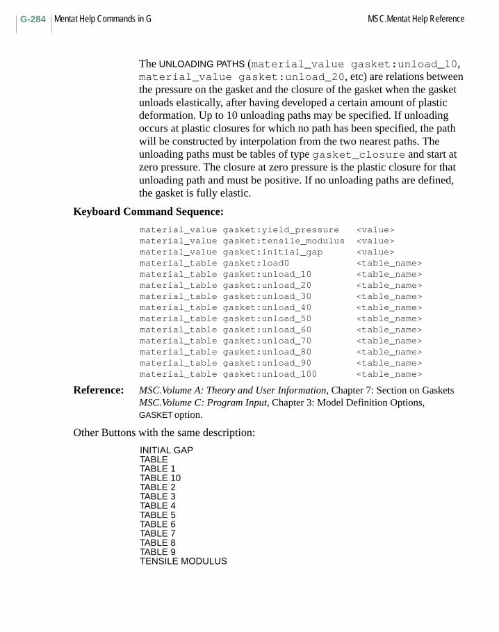
Mentat Help Commands in G MSC.Mentat Help ReferenceG-284
The UNLOADING PATHS (material_value gasket:unload_10, material_value gasket:unload_20, etc) are relations between the pressure on the gasket and the closure of the gasket when the gasket unloads elastically, after having developed a certain amount of plastic deformation. Up to 10 unloading paths may be specified. If unloading occurs at plastic closures for which no path has been specified, the path will be constructed by interpolation from the two nearest paths. The unloading paths must be tables of type gasket_closure and start at zero pressure. The closure at zero pressure is the plastic closure for that unloading path and must be positive. If no unloading paths are defined, the gasket is fully elastic.
Keyboard Command Sequence:
material_value gasket:yield_pressure <value>material_value gasket:tensile_modulus <value>material_value gasket:initial_gap <value>material_table gasket:load0 <table_name>material_table gasket:unload_10 <table_name>material_table gasket:unload_20 <table_name>material_table gasket:unload_30 <table_name>material_table gasket:unload_40 <table_name>material_table gasket:unload_50 <table_name>material_table gasket:unload_60 <table_name>material_table gasket:unload_70 <table_name>material_table gasket:unload_80 <table_name>material_table gasket:unload_90 <table_name>material_table gasket:unload_100 <table_name>
Reference: MSC.Volume A: Theory and User Information, Chapter 7: Section on GasketsMSC.Volume C: Program Input, Chapter 3: Model Definition Options, GASKET option.
Other Buttons with the same description:
INITIAL GAPTABLETABLE 1TABLE 10TABLE 2TABLE 3TABLE 4TABLE 5TABLE 6TABLE 7TABLE 8TABLE 9TENSILE MODULUS

G-285MSC.Mentat Help Reference Mentat Help Commands in G
MODULUS
Command: material_value gasket:tr_shear_modulus
Description: This command sets the transverse shear modulus for the current gasket material. The transverse shear behavior is elastic.
Keyboard Command Sequence:
material_value gasket:tr_shear_modulus <value>
Reference: MSC.Volume A: Theory and User Information, Chapter 7: Section on GasketsMSC.Volume C: Program Input, Chapter 3: Model Definition Options, GASKET option.
MESH CURVES
Command: generate_2d_rebar
Description: This command automatically meshes the given list of curves with line rebar elements between intersections with existing 2-D mesh.
The 2-D elements are optionally placed into insert set as host elements, while the line elements are placed into insert set as embedded elements.
Also see help: set_insert_create
Keyboard Command Sequence:
generate_2d_rebar <curve list> <element list>
MODULUS
MESH CURVES
Mentat Help Commands in G MSC.Mentat Help ReferenceG-286
GENERATE (AT CENTER)
Command: generate_csect_control_node
Description: This command creates a control node and assigns it to the current cross-section. The position vector of the control node is given by the average position vectors of the cross-section nodes. In this way, defining boundary conditions on the control nodes and performing postprocessing might be easier if there are several cross-sections present in the model, since the position vector of each control node is related to the location of the corresponding cross-section.
Alternatively, if the user has defined a separate node in the model, the command set_csect_control_node can be used to assign this node to the current cross-section.
Keyboard Command Sequence:
generate_csect_control_node
GENSTR
Subroutine: GENSTR
Description: The user subroutine GENSTR allows you to enter the generalized stress-strain law for shells and beams which are conventionally integrated through their thickness. This is often convenient in composite analysis, where the experimental information is for the total material, not individual plies. GENSTR is activated using the SHELL SECT parameter data blocks. As no layer integration is performed, the number of layers may be set to one.
GENERATE (AT CENTER)
GENSTR
G-287MSC.Mentat Help Reference Mentat Help Commands in G
GENT
Command: gent
Description: Elastomer Free Energy Function
Number of coefficients 2
Reference: Gent, A.N. "A New Constitutive Relation for Rubber" Rubber Chemistry and Technology, Vol.79, pp. 59-61, 1996
Coefficient: E, I_m – Determined by the fitter
E: Small strain tensile modulus
I_m: maximum value for the first invariant of deformation (I1)
Warning: This phenomenological model is designed to exhibit finite extensibility of polymer chains and forces the stresses and tangent to asymptote to infinity as I1 approaches Im. It is conceivable that during the solution stage, Marc evaluates a set of trial displacements such that I1 > Im. In which case, the convergence ratios can be expected to oscillate, or even worse, the solution may not converge at all. Therefore, if Im < 4, it is recommended that in a Marc job, users apply loads in small increments.
For this model, the calculation of the Bulk Modulus is not required by the Marc program. A volumetric test need not be supplied.
GEOMETRIC PROPERTIES
Menu: GEOMETRIC PROPERTIES
Description: This menu contains commands for defining sets of geometric properties and applying them to elements in the model. The types of properties that can be defined are truss area, beam properties, and shell thickness.
GENT
GEOMETRIC PROPERTIES
Mentat Help Commands in G MSC.Mentat Help ReferenceG-288
GRID DIV.
Menu: GEOMETRY DISTANCE
Description: This menu contains commands for computing the distance of nodes from geometric entities such as curves and surfaces. The results of this compuation are made available as scalar and vector plots. Controls are available to control the accuracy and cost of the computation.
Command: geomdist_surfaces <surface list> <node list>geomdist_curves <curve list> <node list>
For each given node, every given curve, or surface is searched to find the closest point. This search is done in two steps. First a coarse search is performed on a precomputed regular grid of points to find the closest point. Then a binary search is done to tolerance around that location. Tests are done to exclude points outside of trimming curves, and points which are not normal to the surface.
set_geomdist_grid_div <ndiv>
This command is used to set the size of the precomputation grid. For complex surfaces, it may be necessary to increase this number to avoid amibiguous results.
set_geomdist_tolerance <tol>
Set the tolerance to be used during the binary search used to find the closest point. A lower tolerance will improve the accuracy of the results.
set_geomdist_check_trim <on/off>
When searching surfaces having trimming curves, this command will control whether a surface will be excluded when the closest point is outside of the trimming loops. Default on.
set_geomdist_trim_div <ndiv>
When determining whether a point is inside the trimming loops, it is necessary to break each trimming curve into segments. This command controls the number of segments generated by each curve. A larger number of segments will increase the accuracy of this computation.
set_geomdist_trim_tolerance <tol>
This controls the detection of points which are outside of all trimming loops. Trimming loops are actually scaled down very slightly to allow
GEOMETRY DISTANCE

G-289MSC.Mentat Help Reference Mentat Help Commands in G
points which are on the boundary of the underlying surface to be outside of the trimming loops.
set_geomdist_check_normal <on/off>
This command controls normal checking once the closest point on the curve or surface has been found. This is done by comparing the vector between the node and the closest point, and the curve or surface normal. Default on.
set_geomdist_normal_tolerance <tol>
This command sets the tolerance used for normal checking.
Other Buttons with the same description:
CHECK NORMALCHECK TRIMMING CURVESCURVE DISTANCESGRID DIV.NORMAL TOL.RESETSURFACE DISTANCESTOLERANCETRIM DIV.TRIM TOL.
NAME
Command: geometry_name
Description: This command sets or changes the name of the current set of geometric properties.
An element geometry is a collection of the geometric properties to be applied to a set of elements. Geometric properties include but are not limited to shell thickness, beam and truss areas, and beam moments of inertia.
Keyboard Command Sequence:
geometry_name <geometry name>
NAME
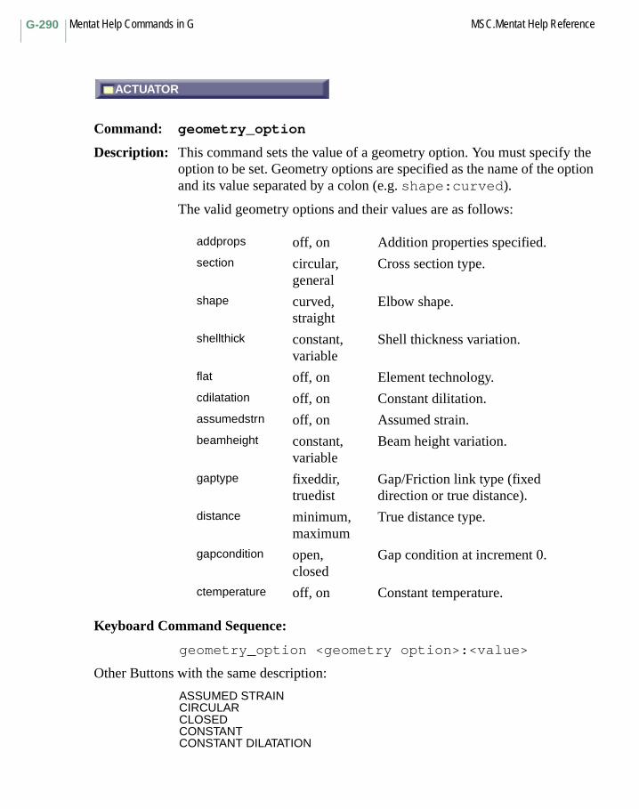
Mentat Help Commands in G MSC.Mentat Help ReferenceG-290
ACTUATOR
Command: geometry_option
Description: This command sets the value of a geometry option. You must specify the option to be set. Geometry options are specified as the name of the option and its value separated by a colon (e.g. shape:curved).
The valid geometry options and their values are as follows:
Keyboard Command Sequence:
geometry_option <geometry option>:<value>
Other Buttons with the same description:
ASSUMED STRAINCIRCULARCLOSEDCONSTANTCONSTANT DILATATION
addprops off, on Addition properties specified.section circular,
generalCross section type.
shape curved, straight
Elbow shape.
shellthick constant, variable
Shell thickness variation.
flat off, on Element technology.cdilatation off, on Constant dilitation.assumedstrn off, on Assumed strain.beamheight constant,
variableBeam height variation.
gaptype fixeddir, truedist
Gap/Friction link type (fixed direction or true distance).
distance minimum, maximum
True distance type.
gapcondition open, closed
Gap condition at increment 0.
ctemperature off, on Constant temperature.
ACTUATOR

G-291MSC.Mentat Help Reference Mentat Help Commands in G
CONSTANT TEMPERATURECURVEDENTERED VALUESFIXED DIRECTIONFLAT ELEMENTGENERALMAXIMUMMINIMUMOFFONOPENSTRAIGHTTRUE DISTANCEUSER SUB. REBARVARIABLE
geometry_reset
Command: geometry_reset
Description: This command resets all geometry values and options for the current geometry to their default values.
Keyboard Command Sequence:
geometry_reset
BEAM SECTION
Command: geometry_section
Description: This command assigns a beam section to the current geometry. Beam section may be assigned to 3-D general beams only.
Keyboard Command Sequence:
geometry_section <beam section name>
geometry_reset
BEAM SECTION

Mentat Help Commands in G MSC.Mentat Help ReferenceG-292
TRUSS
Command: geometry_type
Description: This command selects the type of the current geometry property. You must specify the type of geometry. The valid geometry types are as follows:
heat_three_trussheat_three_shellheat_three_solidheat_three_comp_cont
heat_axisym_shellheat_axisym_solidheat_axisym_comp_cont
heat_planarheat_planar_comp_cont
magn_three_solid
mech_three_trussmech_three_cablemech_three_beam_elamech_three_beam_genmech_three_elbowmech_three_membranemech_three_shearmech_three_shellmech_three_solidmech_three_rebarmech_three_membr_rebarmech_three_comp_cont
mech_axisym_shellmech_axisym_solidmech_axisym_rebarmech_axisym_comp_cont
mech_gap
mech_planar_beam_strmech_planar_beam_curmech_planar_pstressmech_planar_pstrain
TRUSS
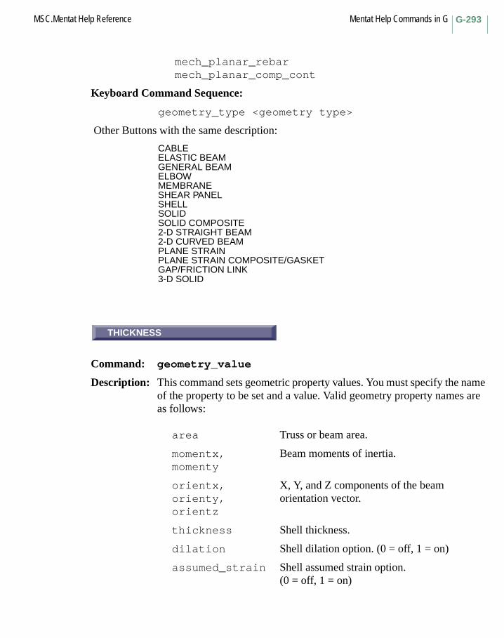
G-293MSC.Mentat Help Reference Mentat Help Commands in G
mech_planar_rebarmech_planar_comp_cont
Keyboard Command Sequence:
geometry_type <geometry type>
Other Buttons with the same description:
CABLEELASTIC BEAMGENERAL BEAMELBOWMEMBRANESHEAR PANELSHELLSOLIDSOLID COMPOSITE 2-D STRAIGHT BEAM2-D CURVED BEAMPLANE STRAINPLANE STRAIN COMPOSITE/GASKETGAP/FRICTION LINK3-D SOLID
THICKNESS
Command: geometry_value
Description: This command sets geometric property values. You must specify the name of the property to be set and a value. Valid geometry property names are as follows:
area Truss or beam area.
momentx,momenty
Beam moments of inertia.
orientx,orienty,orientz
X, Y, and Z components of the beam orientation vector.
thickness Shell thickness.
dilation Shell dilation option. (0 = off, 1 = on)
assumed_strain Shell assumed strain option.(0 = off, 1 = on)
THICKNESS

Mentat Help Commands in G MSC.Mentat Help ReferenceG-294
Keyboard Command Sequence:
geometry_value <property name> <value>
Other Buttons with the same description:
AREAAT 1ST CORNER NODEAT 2ND CORNER NODEAT 3RD CORNER NODEAT 4TH CORNER NODEBENDING RADIUSCENTER POINT XCENTER POINT YCENTER POINT ZCLOSURE DISTANCECONTACT RADIUSDISTANCEEFF. T-SHEAR AREA AxEFF. T-SHEAR AREA AyEMISSIVITYFILM COEFFICIENTFRICTION COEFFICIENTFRICTION DIRECTION XFRICTION DIRECTION YFRICTION DIRECTION ZGAP DIRECTION XGAP DIRECTION YGAP DIRECTION ZHEIGHTINITIAL STRESSIxxIyyLENGTHMOMENTUM RATIO 1ST NODEMOMENTUM RATIO 2ND NODEPENALTYRADIUSSTIFFNESS IN FRICTION DIRECTIOSTIFFNESS IN GAP DIRECTIONTORSIONAL STIFFNESS FACTORTRANSITION THICKNESSVECTOR DEF. LOCAL X-AXIS XVECTOR DEF. LOCAL X-AXIS YVECTOR DEF. LOCAL X-AXIS ZWIDTHXYZ

G-295MSC.Mentat Help Reference Mentat Help Commands in G
GLOBAL REMESHING
Menu: GLOBAL REMESHING
Description: This menu contains commands for defining the parameters used to control the global remeshing.
Global remeshing allows different parts of the model to be remeshed. A new mesh is automatically created, relevant solution quantities are transfered to the new mesh and the analysis continues.
This feature is currently only supported for contact bodies and only boundary conditions applied with contact bodies are allowed on the remeshed body. The remeshing is performed separately for each contact body.
Only 2-D problems can use remeshing in this release.
U DOMAIN
Command: grid_u_domaingrid_v_domaingrid_w_domain
grid_u_spacinggrid_v_spacinggrid_w_spacing
grid_u_positiongrid_v_positiongrid_w_position
grid_fix_ugrid_fix_vgrid_fix_w
grid_style_dotsgrid_style_linesgrid_maxpoints
GLOBAL REMESHING
U DOMAIN
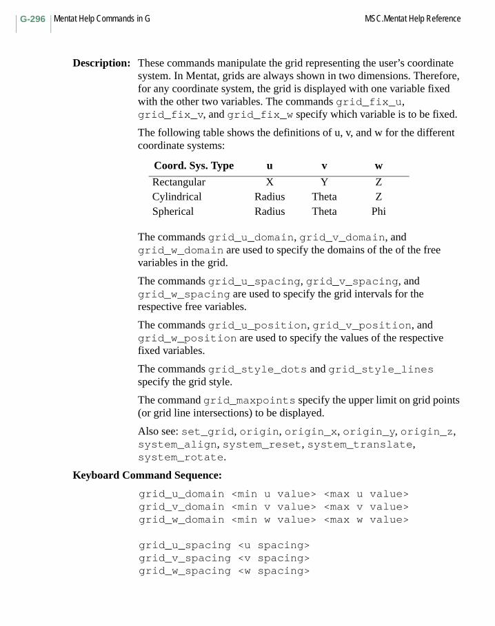
Mentat Help Commands in G MSC.Mentat Help ReferenceG-296
Description: These commands manipulate the grid representing the user’s coordinate system. In Mentat, grids are always shown in two dimensions. Therefore, for any coordinate system, the grid is displayed with one variable fixed with the other two variables. The commands grid_fix_u, grid_fix_v, and grid_fix_w specify which variable is to be fixed.
The following table shows the definitions of u, v, and w for the different coordinate systems:
The commands grid_u_domain, grid_v_domain, and grid_w_domain are used to specify the domains of the of the free variables in the grid.
The commands grid_u_spacing, grid_v_spacing, and grid_w_spacing are used to specify the grid intervals for the respective free variables.
The commands grid_u_position, grid_v_position, and grid_w_position are used to specify the values of the respective fixed variables.
The commands grid_style_dots and grid_style_lines specify the grid style.
The command grid_maxpoints specify the upper limit on grid points (or grid line intersections) to be displayed.
Also see: set_grid, origin, origin_x, origin_y, origin_z, system_align, system_reset, system_translate, system_rotate.
Keyboard Command Sequence:
grid_u_domain <min u value> <max u value>grid_v_domain <min v value> <max v value>grid_w_domain <min w value> <max w value>
grid_u_spacing <u spacing>grid_v_spacing <v spacing>grid_w_spacing <w spacing>
Coord. Sys. Type u v w
Rectangular X Y ZCylindrical Radius Theta ZSpherical Radius Theta Phi

G-297MSC.Mentat Help Reference Mentat Help Commands in G
grid_u_position <u position>grid_v_position <v position>grid_w_position <w position>
grid_fix_ugrid_fix_vgrid_fix_w
grid_style_dotsgrid_style_lines
grid_maxpoints <max # points>
Other Buttons with the same description:
DOTSFIX UFIX VFIX WLINESMAX POINTSUU SPACINGVV DOMAINV SPACINGWW DOMAINW SPACING

Mentat Help Commands in G MSC.Mentat Help ReferenceG-298

Mentat Help Commands in Hhelp
Command: help
Description: This command displays the help text for the specified command.
Keyboard Command Sequence:
help <command>
H Commands Begin with H
help
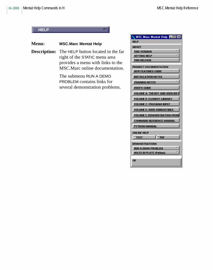
Mentat Help Commands in H MSC.Mentat Help ReferenceH-300
TEXT
Menu: MSC.Marc Mentat Help
Description: The HELP button located in the far right of the STATIC menu area provides a menu with links to the MSC.Marc online documentation.
The submenu RUN A DEMO PROBLEM contains links for several demonstration problems.
HELP

H-301MSC.Mentat Help Reference Mentat Help Commands in H
TEXT
Command: help_pdf
Description: This command toggles between a text-based online help system and a system via PDF files. The latter requires that a PDF-file reader (such as the Acrobat reader) is installed on the system. The online help system can also be selected at startup via the -ha command line option. In that case, -ha true selects the PDF-based system and -ha false selects the text-based system. The default is to use the PDF files.
The button is located in the HELP menu which can be opened from the HELP button in the far right of the STATIC menu area.
Keyboard Command Sequence: help_pdf <on/off>table_unfilled
Command Line Option:
-ha true/false
Other Buttons with the same description:PDF
DETECT EDGES
Command: hexer_detect_edges
Description: This command is used to automatically detect geometric edges in a list of triangular and quadrilateral elements which enclose a volume. The elements in the input list must be oriented with their tops facing outward, and there must not be any free edges or holes existing in the list.
TEXT
DETECT EDGES
Mentat Help Commands in H MSC.Mentat Help ReferenceH-302
Detected edges are used by HexMesh to help define geometry. The resulting hexahedral mesh will not have any element faces which cross these edges. Detected element edges are left selected by hexer_detect_edges, and then the list of selected edges may be modified before using HexMesh. Proper selection of these edges is important so that the mesh will accurately represent the geometry of the input surface mesh.
Also see help: hexer_hexmesh and hexmesh_controls.
Keyboard Command Sequence:
hexer_detect_edges <element list>
HEXMESH!
Command: hexer_hexmesh
Description: This command runs the automatic hexahedral mesh generator, HexMesh. For input, a list of triangular and quadrilateral elements which enclose a volume is required. The elements must be oriented with their tops facing outward, and there must not be any free edges or holes existing in the list.
If any element edges are selected, then these edges will be used by the mesher to help define geometry. The resulting hexahedral mesh will not have any element faces which cross these edges. Proper selection of these edges is important so that the mesh will accurately represent the geometry of the input surface mesh.
If no element edges are selected, then the mesher will automatically detect edges according to the current edge sensitivity parameter as part of the meshing process.
Also see help: hexmesh_controls, hexer_detect_edges.
Keyboard Command Sequence:
hexer_hexmesh <element list>
HEXMESH!

H-303MSC.Mentat Help Reference Mentat Help Commands in H
ELEMENT SIZE
Command: hexmesh_controls
Description: The following parameters relate to HexMesh:
ELEMENT SIZE (XYZ) The desired size of the hexahedral elements being generated in the x, y, and z-directions.
EDGE SENSITIVITY Used during edge detection to determine when the shared edge between two input elements represents a real edge. A value of one means that all element edges between elements which do not lie in the same plane will be treated as real edges. A value of zero means that no real edges will be found.
GAP Nonzero values for this parameter will affect the size of the gap which is initially left between the inner (kernel) hexahedral elements and the surface during mesh generation. Negative values will result in a smaller gap (even penetration) and positive values will result in a wider gap. The value of this parameter must be between -1 and 1.
SHAKES The number of times to shake the mesh, where shaking is a method of global mesh enhancement.
RUNS The maximum number of times the mesher is allowed to run. The mesher reruns with a smaller element size if it fails.
COARSENING LEVELS To reduce the number of generated elements, larger elements may be produced in the interior of the mesh. Tying equations are used to maintain compatibility of neighboring elements. A value of zero indicates that no coarsening will occur, while a value of two indicates that the elements in the interior can be up to four times larger on each side than elements on the surface. Acceptable values are 0, 1, and 2.
ELEMENT SIZE
Mentat Help Commands in H MSC.Mentat Help ReferenceH-304
LOCAL ENHANCE Setting this parameter causes the mesher to perform some additional mesh enhancement within localized areas.
COONS PATCHES Turning on this option allows a smoother representation of the input surface to be used, resulting in a better approximation of the input geometry than by just using quadrilaterals and triangles. This approach is however more costly in CPU time.
ALLOW WEDGES When this option is on, the creation of wedge elements is allowed if an edge crosses the diagonal of a face of the hexahedral element.
Also see help: hexer_detect_edges, hexer_hexmesh.
Keyboard Command Sequence:
set_hexer_element_size <size_x> <size_y> <size_z>set_hexer_edge_sensitivity <sensitivity>set_hexer_gap <gap>set_hexer_shakes <number of shakes>set_hexer_runs <number of runs>set_hexer_coarsening_levels <number of levels>set_hexer_local_enhance <y or n>set_hexer_coons_patches <y or n>set_hexer_allow_wedges <y or n>
Other Buttons with the same description:
012ALLOW WEDGESCOONS PATCHESEDGE SENS.GAPRUNSSHAKES
H-305MSC.Mentat Help Reference Mentat Help Commands in H
ADD 1-NODE CURVE
Command: history_add
Description: This command adds a single curve based on a single node to a history plot. You must already have collected history plotting data (see set_history_nodes and history_collect). You must specify the node for which you want the plot, x-axis and y-axis variables.
Keyboard Command Sequence:
history_add <node> <X-variable> <Y-variable>
ADD 2-NODE CRV
Command: history_add_2nodes
Description: This command adds a single curve based on two nodes to a history plot. You must already have collected history plotting data (see set_history_nodes and history_collect). You must specify the x-axis node, x-axis variable, y-axis node, and y-axis variable.
Keyboard Command Sequence:
history_add_2nodes <X-node> <X-variable> <Y-node><Y-variable>
ADD NODE
Command: history_add_node
Description: This command adds a family of curves based on a single node to a history plot. You must already have collected history plotting data (see set_history_nodes and history_collect). One curve for every result variable in the results file will be added. You must specify the node for which you want the plot and x-axis variable.
Keyboard Command Sequence:
history_add_node <node> <X-variable>
ADD 1-NODE CURVE
ADD 2-NODE CRV
ADD NODE
Mentat Help Commands in H MSC.Mentat Help ReferenceH-306
ADD GLOBAL CRV
Command: history_add_nodeless
Description: This command adds a single history curve based on data not associated with any node, such as die forces and optimization data, to a history plot. You must already have collected history plotting data (see history_collect). You must specify the x-axis and y-axis variables.
Keyboard Command Sequence:
history_add_nodeless <X-variable> <Y-variable>
ADD VARIABLE
Command: history_add_var
Description: This command adds a family of curves each based on a different single node to a history plot. You must already have collected history plotting data (see set_history_nodes and history_collect). One curve for every node in the model will be added. You must specify the x-axis and y-axis variables.
Keyboard Command Sequence:
history_add_var <X-variable> <Y-variable>
CLEAR CURVES
Command: history_clear
Description: This command clears all curves from the history plot.
Keyboard Command Sequence:
history_clear
ADD GLOBAL CRV
ADD VARIABLE
CLEAR CURVES

H-307MSC.Mentat Help Reference Mentat Help Commands in H
COLLECT DATA
Command: history_collect
Description: This command collects from the current results file from which history plots can be made. Data may be collected from every increment in the file or from regularly spaced increments. You must provide the first and last increment numbers and an increment step size. Increment numbers are in the form Inc:Sub. That is, an increment number followed by a colon and the subincrement number. If the colon and subincrement number are left off, then the subincrement is assumed to be 0.
Note that you can collect either from Inc1:Sub to Inc2:Sub or from Inc:Sub1 to Inc:Sub2, so incremental and subincremental data cannot be collected together.
Keyboard Command Sequence:
history_collect <first increment><last increment> <step size>
Another Button with the same description:
COLLECT GLOBAL DATA
FILLED
Command: history_filled
Description: This command causes areas under history curves to be unfilled. To fill plots with color, toggle this button ON to use the history_filled command.
Keyboard Command Sequence:
history_filled
COLLECT DATA
FILLED

Mentat Help Commands in H MSC.Mentat Help ReferenceH-308
FIT
Command: history_fit
Description: This command alters the limits of the history plots so that all values fit onto the screen.
Keyboard Command Sequence:
history_fit
BODY FORCE vs. BODY ANGLE
Menu: HISTORY PLOT PRESETS
Description: The commands in this menu add curves with predefined X- and Y-variable to a history plot.
You do not need to have the collected history plotting data.
Commands for which the X- and/or Y-variable represent contact body data, add a curve for each contact body in the model.
Keyboard Command Sequence:
history_add_body_force_timehistory_add_body_force_body_poshistory_add_body_force_body_anglehistory_add_body_force_press_angle (only AutoForge)
Other Buttons with the same description:
BODY FORCE vs. BODY POSITIONBODY FORCE vs. TIMEPRESETS
FIT
BODY FORCE vs. BODY ANGLE

H-309MSC.Mentat Help Reference Mentat Help Commands in H
REMOVE CURVE
Command: history_remove
Description: This command removes curves from the history plot. You must specify the curve to be removed.
Keyboard Command Sequence:
history_remove <history curve number>
CONVERT
Command: history_table
Description: This command creates a table from the values in the specified history curve. History curves are specified by number.
Keyboard Command Sequence:
history_table <history curve number>
FILLED
Command: history_unfilled
Description: This command causes areas under history curves to be unfilled. To fill plots with color, toggle this button ON to use the history_filled command.
Keyboard Command Sequence:
history_unfilled
REMOVE CURVE
CONVERT
FILLED
Mentat Help Commands in H MSC.Mentat Help ReferenceH-310
SAVE
Command: history_write
Description: This command writes the current history curves to a file. You must specify the name of the file to receive the data.
Keyboard Command Sequence:
history_write <file name>
HITCHCOCK IN
Command: hitchcock_in
Description: This command moves the camera toward the lookat point, and zooms the camera out. First, if the projection is currently orthographic, it is changed to perspective. Then, the camera is moved so that its distance from the lookat point is divided by the current zoom increment. Finally, the camera zoom is divided by the current zoom increment. This has the effect of increasing the amount of perspective in the view. After using this command, objects behind the lookat point may appear smaller than before, objects at the lookat point will look the same, and objects in front of the lookat point may appear larger.
This command acts on all the currently active views.
Also see: hitchcock_out, view_perspective, view_viewpoint, zoom_increment, view_zoom_factor, activate_view, and the topic viewing for a general discussion of viewing.
Keyboard Command Sequence:
hitchcock_in
SAVE
HITCHCOCK IN
H-311MSC.Mentat Help Reference Mentat Help Commands in H
HITCHCOCK OUT
Command: hitchcock_out
Description: This command moves the camera away from the lookat point, and zooms the camera in. First, if the projection is currently orthographic, it is changed to perspective. Then, the camera is moved so that its distance from the lookat point is multiplied by the current zoom increment. Finally, the camera zoom is multiplied by the current zoom increment. This has the effect of decreasing the amount of perspective in the view. After using this command, objects behind the lookat point may appear larger than before, objects at the lookat point will look the same, and objects in front of the lookat point may appear smaller.
This command acts on all the currently active views.
Also see: hitchcock_in, view_perspective, view_viewpoint, zoom_increment, view_zoom_factor, activate_view, and the topic viewing for a general discussion of viewing.
Keyboard Command Sequence:
hitchcock_out
HOLES IN PLATE (Python)
Menu: HOLES IN PLATE (Python)
Description: This button will run the demonstration problem for Python. It is the example shown in the MSC.Marc Python Tutorial: Chapter 4, describing a parametric design example in which the number of holes to place in a plate are determined by the Python script.
Selecting this button brings up a dialog box that contains 4 text boxes. The variables assigned to these boxes represent the width, height, hole diameter, and hole spacing values.
To run this example, you must set your current directory to be examples/python/tutorial/c04.
HITCHCOCK OUT
HOLES IN PLATE (Python)
Mentat Help Commands in H MSC.Mentat Help ReferenceH-312
HOOKLW
Subroutine: HOOKLW
Description: The user subroutine HOOKLW is an alternative mechanism to user subroutine ANELAS. In this routine, you supply the elastic stress-strain law. This law is given in terms of the coordinate system defined in the ORIENTATION option. You should insure that the stress-strain law is symmetric. Note that this routine will be called for each integration point of those elements that have anisotropic properties. You may define either the stress-strain relation or the compliance strain-stress relation. The returned value of argument IMOD must be set accordingly.
HOOKVI
Subroutine: HOOKVI
Description: The user subroutine HOOKVI allows you to modify the time dependent properties of an orthotropic material specified through the VISCELORTH Model Definition option.
HOOKVI is automatically called for every material defined in that option.
HYPELA
Subroutine: HYPELA
Description: The user subroutine HYPELA allows you to define elastic constants as functions of elastic strain and state variables.
HOOKLW
HOOKVI
HYPELA
Mentat Help Commands in IALL
Command: icond_all_layers
Description: This command activates all element layers for the current state variable initial condition.
Keyboard Command Sequence: icond_all_layers
ON
Command: icond_dofclear_icond_dof
Description: These commands add and clear the specified degree of freedom from the current initial condition.
Keyboard Command Sequence: icond_dof <dof name>clear_icond_dof <dof name>
I Commands Begin with I
ALL
ON
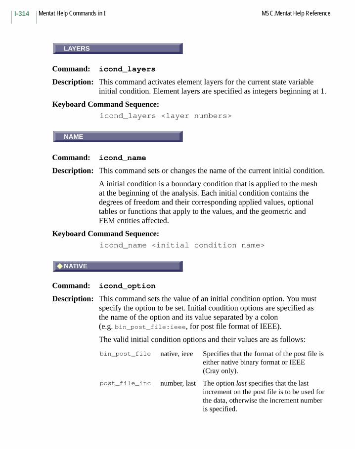
Mentat Help Commands in I MSC.Mentat Help ReferenceI-314
LAYERS
Command: icond_layers
Description: This command activates element layers for the current state variable initial condition. Element layers are specified as integers beginning at 1.
Keyboard Command Sequence: icond_layers <layer numbers>
NAME
Command: icond_name
Description: This command sets or changes the name of the current initial condition.
A initial condition is a boundary condition that is applied to the mesh at the beginning of the analysis. Each initial condition contains the degrees of freedom and their corresponding applied values, optional tables or functions that apply to the values, and the geometric and FEM entities affected.
Keyboard Command Sequence: icond_name <initial condition name>
# NATIVE
Command: icond_option
Description: This command sets the value of an initial condition option. You must specify the option to be set. Initial condition options are specified as the name of the option and its value separated by a colon (e.g. bin_post_file:ieee, for post file format of IEEE).
The valid initial condition options and their values are as follows:
bin_post_file native, ieee Specifies that the format of the post file is either native binary format or IEEE (Cray only).
post_file_inc number, last The option last specifies that the last increment on the post file is to be used for the data, otherwise the increment number is specified.
LAYERS
NAME
NATIVE
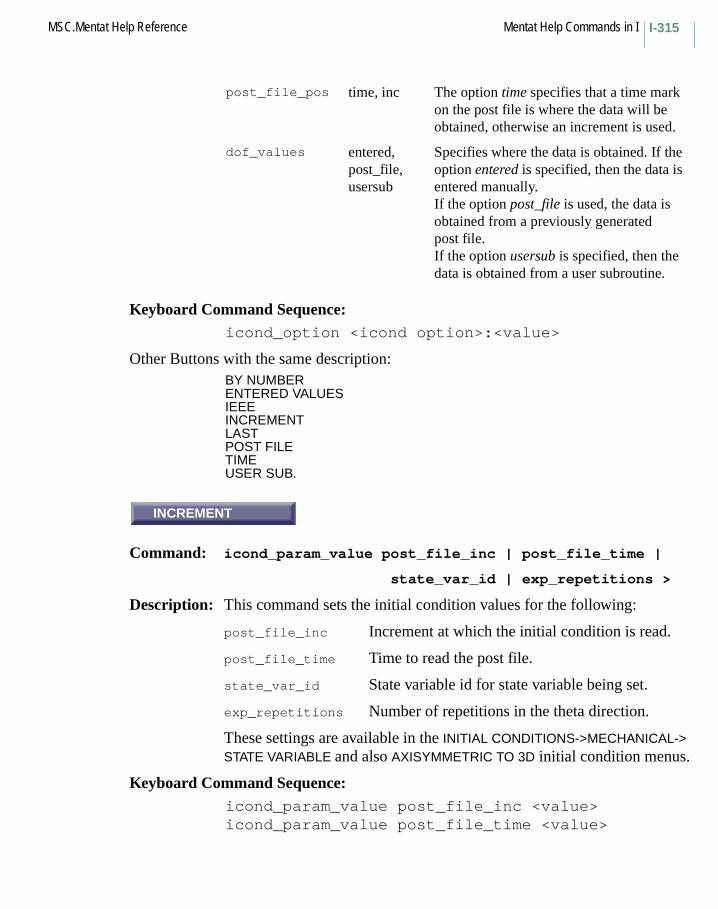
I-315MSC.Mentat Help Reference Mentat Help Commands in I
Keyboard Command Sequence: icond_option <icond option>:<value>
Other Buttons with the same description:BY NUMBERENTERED VALUESIEEEINCREMENTLASTPOST FILETIMEUSER SUB.
INCREMENT
Command: icond_param_value post_file_inc | post_file_time |
state_var_id | exp_repetitions >
Description: This command sets the initial condition values for the following:
post_file_inc Increment at which the initial condition is read.
post_file_time Time to read the post file.
state_var_id State variable id for state variable being set.
exp_repetitions Number of repetitions in the theta direction.
These settings are available in the INITIAL CONDITIONS->MECHANICAL-> STATE VARIABLE and also AXISYMMETRIC TO 3D initial condition menus.
Keyboard Command Sequence: icond_param_value post_file_inc <value>icond_param_value post_file_time <value>
post_file_pos time, inc The option time specifies that a time mark on the post file is where the data will be obtained, otherwise an increment is used.
dof_values entered,post_file,usersub
Specifies where the data is obtained. If the option entered is specified, then the data is entered manually.If the option post_file is used, the data is obtained from a previously generated post file.If the option usersub is specified, then the data is obtained from a user subroutine.
INCREMENT

Mentat Help Commands in I MSC.Mentat Help ReferenceI-316
icond_param_value state_var_id <value>icond_param_value exp_repetitions <value>
Other Buttons with the same description:SETSTATE VARIABLE IDEXPAND REPETITIONS
POST FILE
Command: icond_post_file
Description: This command specifies the name of the post file to be used for reading values for the current state variable initial condition.
Keyboard Command Sequence:
icond_post_file <post file name>
INCREMENT
Command: icond_post_increment
Description: This command specifies the first increment to be read from the post file to provide values for the state variable initial condition.
Keyboard Command Sequence:
icond_post_increment <increment number>
Another Button with the same description:
SET
POST FILE
INCREMENT
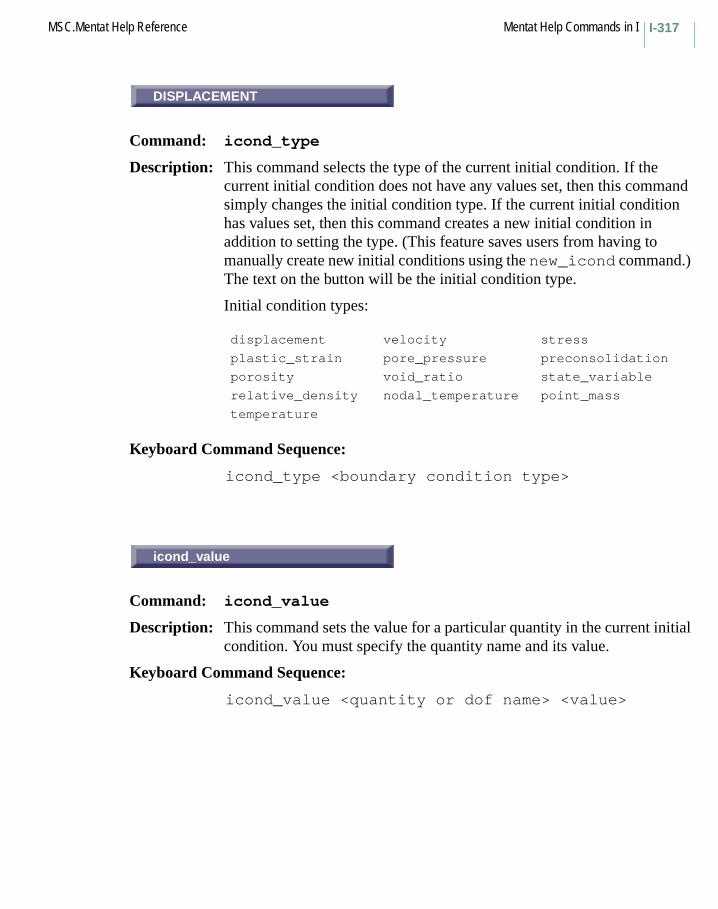
I-317MSC.Mentat Help Reference Mentat Help Commands in I
DISPLACEMENT
Command: icond_type
Description: This command selects the type of the current initial condition. If the current initial condition does not have any values set, then this command simply changes the initial condition type. If the current initial condition has values set, then this command creates a new initial condition in addition to setting the type. (This feature saves users from having to manually create new initial conditions using the new_icond command.) The text on the button will be the initial condition type.
Initial condition types:
Keyboard Command Sequence:
icond_type <boundary condition type>
icond_value
Command: icond_value
Description: This command sets the value for a particular quantity in the current initial condition. You must specify the quantity name and its value.
Keyboard Command Sequence:
icond_value <quantity or dof name> <value>
displacement velocity stress
plastic_strain pore_pressure preconsolidation
porosity void_ratio state_variable
relative_density nodal_temperature point_mass
temperature
DISPLACEMENT
icond_value
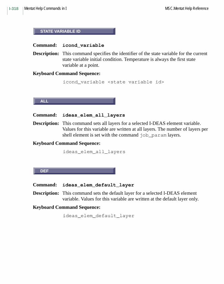
Mentat Help Commands in I MSC.Mentat Help ReferenceI-318
STATE VARIABLE ID
Command: icond_variable
Description: This command specifies the identifier of the state variable for the current state variable initial condition. Temperature is always the first state variable at a point.
Keyboard Command Sequence:
icond_variable <state variable id>
ALL
Command: ideas_elem_all_layers
Description: This command sets all layers for a selected I-DEAS element variable. Values for this variable are written at all layers. The number of layers per shell element is set with the command job_param layers.
Keyboard Command Sequence:
ideas_elem_all_layers
DEF
Command: ideas_elem_default_layer
Description: This command sets the default layer for a selected I-DEAS element variable. Values for this variable are written at the default layer only.
Keyboard Command Sequence:
ideas_elem_default_layer
STATE VARIABLE ID
ALL
DEF
I-319MSC.Mentat Help Reference Mentat Help Commands in I
LAYERS
Command: ideas_elem_layers
Description: This command sets the layers for a selected I-DEAS element variable. Values for this variable are written at the specified layers only.
Keyboard Command Sequence:
ideas_elem_layers <layers>
OUT
Command: ideas_elem_outer_layers
Description: This command sets the outer and middle layers for a selected I-DEAS element variable. Values for this variable are written at the outer and middle layers only.
Keyboard Command Sequence:
ideas_elem_outer_layers
ALL
Command: ideas_elnod_all_layers
Description: This command sets all layers for a selected I-DEAS element-at-node variable. Values for this variable are written at all layers. The number of layers per shell element is set with the command job_param layers.
Keyboard Command Sequence:
ideas_elnod_all_layers
LAYERS
OUT
ALL
Mentat Help Commands in I MSC.Mentat Help ReferenceI-320
DEF
Command: ideas_elnod_default_layer
Description: This command sets the default layer for a selected I-DEAS element-at-node variable. Values for this variable are written at the default layer only.
Keyboard Command Sequence:
ideas_elnod_default_layer
LAYERS
Command: ideas_elnod_layers
Description: This command sets the layers for a selected I-DEAS element-at-node variable. Values for this variable are written at the specified layers only.
Keyboard Command Sequence:
ideas_elnod_layers <layers>
OUT
Command: ideas_elnod_outer_layers
Description: This command sets the outer and middle layers for a selected I-DEAS element-at-node variable. Values for this variable are written at the outer and middle layers only.
Keyboard Command Sequence:
ideas_elnod_outer_layers
DEF
LAYERS
OUT

I-321MSC.Mentat Help Reference Mentat Help Commands in I
GLBL RMSH CRIT
Command: identify_adapgs
Description: This command turns on the identification of entries in the list of global remeshing criteria.
Keyboard Command Sequence:
identify_adapgs
Another Button with the same description:
ID GLOBAL REMESHING CRITERIA
ID LOCAL ADAPTIVITY CRITERIA
Command: identify_adapts
Description: This command turns on the identification of adaptivity criteria.
Keyboard Command Sequence:
identify_adapts
Another Button with the same description:
LCL ADPT CRIT
BOUND CONDS
Command: identify_applys
Description: This command turns on the identification of boundary condition applications.
Keyboard Command Sequence:
identify_applys
Other Buttons with the same description:
BOUNDARY CONDSID BOUNDARY CONDS
GLBL RMSH CRIT
ID LOCAL ADAPTIVITY CRITERIA
BOUND CONDS

Mentat Help Commands in I MSC.Mentat Help ReferenceI-322
BACKFACES
Command: identify_backfaces
Description: This command turns on the identification of backfacing polygons. Front/inside denotes the inside of the rigid body. The contacting body should be on the outside part of the rigid surface, by default colored brown.
Keyboard Command Sequence:
identify_backfaces
Another Button with the same description:
ID BACKFACES
CLASSES
Command: identify_classes
Description: This command turns on the identification of classes of polygons.
Keyboard Command Sequence:
identify_classes
Another Button with the same description:
ID CLASSES
CONTACT
Command: identify_contact
Description: This command turns on the identification of contact bodies.
Keyboard Command Sequence:
identify_contact
Another Button with the same description:
ID CONTACT
BACKFACES
CLASSES
CONTACT

I-323MSC.Mentat Help Reference Mentat Help Commands in I
DOMAINS
Command: identify_domains
Description: This command turns on the identification of domain decomposition element domains.
Keyboard Command Sequence:
identify_domains
Another Button with the same description:
ID DOMAINS
GEOMETRIES
Command: identify_geometries
Description: This command turns on the identification types of geometry contained in the model.
Keyboard Command Sequence:
identify_geometries
Another Button with the same description:
ID GEOMETRIES
ID INITIAL CONDS
Command: identify_iconds
Description: This command turns on the identification of initial boundary conditions.
Keyboard Command Sequence:
identify_iconds
Other Buttons with the same description:
INIT CONDSINITIAL CONDS
DOMAINS
GEOMETRIES
ID INITIAL CONDS
Mentat Help Commands in I MSC.Mentat Help ReferenceI-324
INSERTS
Command: identify_inserts
Description: This command turns on the identification of inserts.
Keyboard Command Sequence:
identify_inserts
ID MATERIALS
Command: identify_materials
Description: This command turns on the identification of materials.
Keyboard Command Sequence:
identify_materials
Another Button with the same description:
MATERIALS
NONE
Command: identify_none
Description: This command turns off the identification feature.
Keyboard Command Sequence:
identify_none
INSERTS
ID MATERIALS
NONE

I-325MSC.Mentat Help Reference Mentat Help Commands in I
ID SETS
Command: identify_sets
Description: This command turns on the identification of set identifiers of all sets in the model.
Keyboard Command Sequence:
identify_sets
Another Button with the same description:
SETS
ID TYPES
Command: identify_types
Description: This command turns on the identification of Marc element types in the model.
Keyboard Command Sequence:
identify_types
Another Button with the same description:
TYPES
DISPLAY
Command: image_display
Description: This command brings up a new window displaying an image file. The image is displayed at its normal size.
To make the image window go away, move the mouse to the image window and press q or the ESC key.
You must specify the image file name.
Also see: image_save_rgb, render, and image_slide.
ID SETS
ID TYPES
DISPLAY
Mentat Help Commands in I MSC.Mentat Help ReferenceI-326
Keyboard Command Sequence:
image_display <file name>
Another Button with the same description:
IRIS RGB
PAGE HEIGHT
Command: image_ps_height
Description: This command allows you to specify the height of the page in inches for subsequent PostScript plotting of image files.
You must specify the page height.
Also see: image_save_ps, render, image_ps_print, and image_ps_width.
Keyboard Command Sequence:
image_ps_height <height>
PRINT 1
Command: image_ps_print
Description: This command sends a PostScript file containing a copy of a specified image file to a specified printer. Each printer may be configured by editing the appropriate file in the tools directory.
You must specify the printer number and image file name.
Also see: image_save_ps, render, and image_ps_write.
Keyboard Command Sequence:
image_ps_print <printer number> <file name>
Other Buttons with the same description:
PRINT 2PRINT 3
PAGE HEIGHT
PRINT 1
I-327MSC.Mentat Help Reference Mentat Help Commands in I
PAGE WIDTH
Command: image_ps_width
Description: This command allows you to specify the width of the page in inches for subsequent PostScript plotting of image files.
You must specify the page width.
Also see: image_save_ps, render, image_ps_print, and image_ps_height.
Keyboard Command Sequence:
image_ps_width <width>
image_ps_write
Command: image_ps_write
Description: This command converts a specified image file into a PostScript file.
You must specify the image file name.
Also see: image_save_ps, render, and image_ps_print.
Keyboard Command Sequence: image_ps_write <file name> <yes/no>
X ORIGIN
Command: image_ps_xorg
Description: This command allows you to specify the X origin of the image in inches for subsequent PostScript plotting of image files.
You must specify the image X origin.
See also image_save_ps, render, image_ps_print, and image_ps_yorg.
Keyboard Command Sequence: image_ps_xorg <X origin>
PAGE WIDTH
image_ps_write
X ORIGIN

Mentat Help Commands in I MSC.Mentat Help ReferenceI-328
Y ORIGIN
Command: image_ps_yorg
Description: This command allows you to specify the Y origin of the image in inches for subsequent PostScript plotting of image files.
You must specify the image Y origin.
Also see: image_save_ps, render, image_ps_print, and image_ps_xorg.
Keyboard Command Sequence: image_ps_yorg <Y origin>
image_save
Command: image_save_rgb
Description: This command captures the appearance of the graphics window into an IRIS RBG format file. This is like taking a snapshot of the graphics area.
Make sure the graphics window is not obscured by another window while the snapshot is taken.
On some systems, the quality of the saved image may be improved by switching the program into single-buffered mode before taking the snapshot.
You must specify the number of the view to capture, and the image file name.
Also see: image_display, image_slide, set_buffered, and render.
Keyboard Command Sequence:
image_save_rgb <view> <file name> <yes or no>
Y ORIGIN
image_save

I-329MSC.Mentat Help Reference Mentat Help Commands in I
1
Command: image_save_bmp
Description: This command captures the appearance of the graphics window into an MS-Windows BMP image file. This is like taking a snapshot of the graphics area.
Make sure the graphics window is not obscured by another window while the snapshot is taken.
On some systems, the quality of the saved image may be improved by switching the program into single-buffered mode before taking the snapshot.
You must specify the number of the view to capture, and the image file name.
Also see: image_save and set_buffered.
Keyboard Command Sequence:
image_save_bmp <view> <file name> <yes or no>
Other Buttons with the same description:
234
1
Command: image_save_gif
Description: This command captures the appearance of the graphics window into a GIF image file. This is like taking a snapshot of the graphics area.
Make sure the graphics window is not obscured by another window while the snapshot is taken.
On some systems, the quality of the saved image may be improved by switching the program into single-buffered mode before taking the snapshot.
1
1

Mentat Help Commands in I MSC.Mentat Help ReferenceI-330
You must specify the number of the view to capture and the image file name.
Also see: image_save and set_buffered.
Keyboard Command Sequence:
image_save_gif <view> <file name> <yes or no>
Other Buttons with the same description:
234
1
Command: image_save_jpeg
Description: This command captures the appearance of the graphics window into a JPEG image file. This is like taking a snapshot of the graphics area.
Make sure the graphics window is not obscured by another window while the snapshot is taken.
On some systems, the quality of the saved image may be improved by switching the program into single-buffered mode before taking the snapshot.
You must specify the number of the view to capture and the image file name.
Also see: image_save, set_buffered, jpeg_quality, and jpeg_smoothing.
Keyboard Command Sequence:
image_save_jpeg <view> <file name> <yes or no>
Another Button with the same description:
234
1

I-331MSC.Mentat Help Reference Mentat Help Commands in I
1
Command: image_save_ppm
Description: This command captures the appearance of the graphics window into a PPM image file. This is like taking a snapshot of the graphics area.
The PPM image file format is used by the MPEG encoder to generate an MPEG animation file.
Make sure the graphics window is not obscured by another window while the snapshot is taken.
On some systems, the quality of the saved image may be improved by switching the program into single-buffered mode before taking the snapshot.
You must specify the number of the view to capture, and the image file name.
Also see: image_save, set_buffered.
Keyboard Command Sequence:
image_save_ppm <view> <file name> <yes or no>
Other Buttons with the same description:
234
1
Mentat Help Commands in I MSC.Mentat Help ReferenceI-332
1
Command: image_save_ps
Description: This command captures the appearance of the graphics window into a Postscript file. This is like taking a snapshot of the graphics area.
Make sure the graphics window is not obscured by another window while the snapshot is taken.
On some systems, the quality of the saved image may be improved by switching the program into single-buffered mode before taking the snapshot.
You must specify the number of the view to capture and the image file name.
Also see: image_save and set_buffered.
Keyboard Command Sequence:
image_save_ps <view> <file name> <yes or no>
Another Button with the same description:
234
1

I-333MSC.Mentat Help Reference Mentat Help Commands in I
1
Command: image_save_rgb
Description: This command captures the appearance of the graphics window into an IRIS RBG format file. This is like taking a snapshot of the graphics area.
Make sure the graphics window is not obscured by another window while the snapshot is taken.
On some systems, the quality of the saved image may be improved by switching the program into single-buffered mode before taking the snapshot.
You must specify the number of the view to capture and the image file name.
Also see: image_display, image_slide, set_buffered, and render.
Keyboard Command Sequence:
image_save_rgb <view> <file name> <yes or no>
Other Buttons with the same description:
234
1
Mentat Help Commands in I MSC.Mentat Help ReferenceI-334
1
Command: image_save_tiff
Description: This command captures the appearance of the graphics window into a TIFF image file. This is like taking a snapshot of the graphics area.
Make sure the graphics window is not obscured by another window while the snapshot is taken.
On some systems, the quality of the saved image may be improved by switching the program into single-buffered mode before taking the snapshot.
You must specify the number of the view to capture and the image file name.
Also see: image_save and set_buffered.
Keyboard Command Sequence:
image_save_tiff <view> <file name> <yes or no>
Other Buttons with the same description:
234
1

I-335MSC.Mentat Help Reference Mentat Help Commands in I
IRIS RGB
Command: image_slide
Description: This command brings up a new window displaying an image file. The image is displayed at a size that will fill your screen.
To remove the image window, move the mouse to the image window, and press q or the ESC key.
You must specify the image file name.
Also see: image_save, render, and image_display.
Keyboard Command Sequence:
image_slide <file name>
Another Button with the same description:
SLIDE
IMPD
Subroutine: IMPD
Description: The user subroutine IMPD makes the displacements, coordinates, reaction forces, velocities, and accelerations available at each increment so that you may save them in any form convenient for your postprocessing. During harmonic subincrements, IMPD allows you to obtain the complex displacements and reactions. In heat transfer (or Joule heating) analysis, this subroutine allows you to obtain nodal temperatures, fluxes, and voltages for your postprocessing. This routine is used in conjunction with the UDUMP option.
IRIS RGB
IMPD
Mentat Help Commands in I MSC.Mentat Help ReferenceI-336
IMPORT
Command: import
Description: Here are the different data types that can be translated into Mentat.
Keyboard Command Sequence:
import <Data type> <File name>
ACIS
Command: import acis
Description: This command imports an ACIS file. You must specify the name of the file.
FORMATWhen this is set, it reads in a Binary file (SAB). The default reads in a ASCII file (SAT).
CHECK STATUSOn default, the reader will not check for any errors in the imported file. If this option is turn on, entities in the file are checked for geometric, topological, and data structure errors. Furthermore, error messages are written to a file.
Keyboard Command Sequence:
import acis <ACIS file name>
Note: ACIS v3.0 and earlier version are supported.
Other Buttons with the same description:
READ CHECK LOGacis_screen
MARC I-DEAS PATRANACIS IGES VDAFSDXF NASTRAN
IMPORT
ACIS
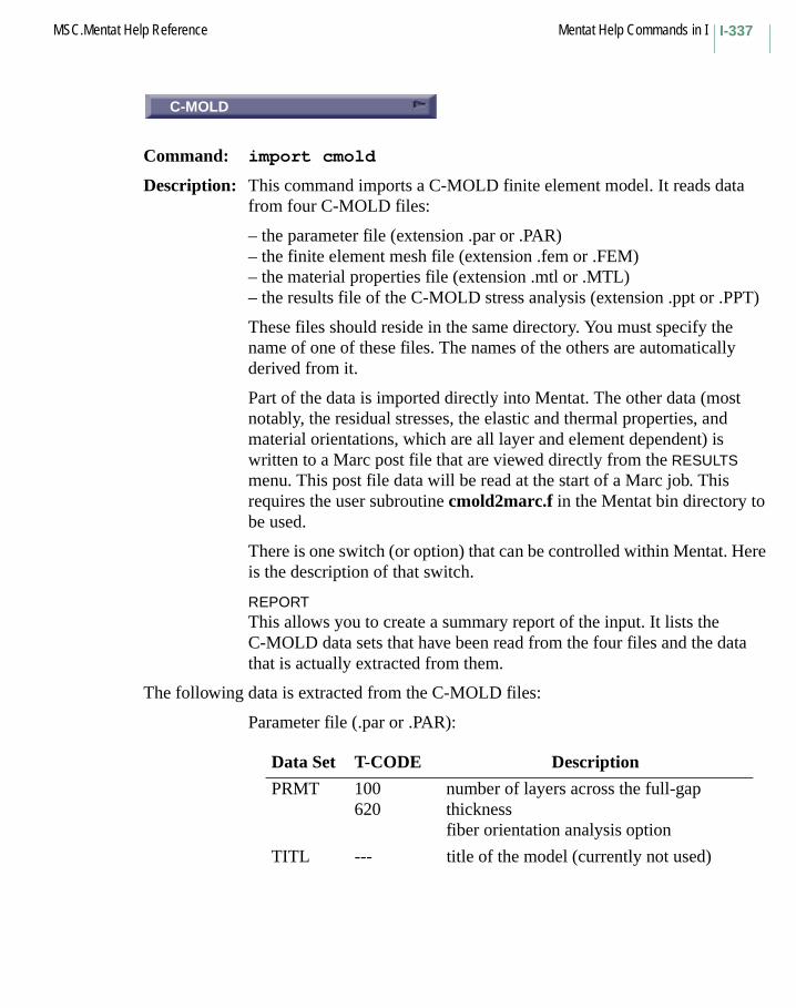
I-337MSC.Mentat Help Reference Mentat Help Commands in I
C-MOLD
Command: import cmold
Description: This command imports a C-MOLD finite element model. It reads data from four C-MOLD files:
– the parameter file (extension .par or .PAR)– the finite element mesh file (extension .fem or .FEM)– the material properties file (extension .mtl or .MTL)– the results file of the C-MOLD stress analysis (extension .ppt or .PPT)
These files should reside in the same directory. You must specify the name of one of these files. The names of the others are automatically derived from it.
Part of the data is imported directly into Mentat. The other data (most notably, the residual stresses, the elastic and thermal properties, and material orientations, which are all layer and element dependent) is written to a Marc post file that are viewed directly from the RESULTS menu. This post file data will be read at the start of a Marc job. This requires the user subroutine cmold2marc.f in the Mentat bin directory to be used.
There is one switch (or option) that can be controlled within Mentat. Here is the description of that switch.
REPORTThis allows you to create a summary report of the input. It lists the C-MOLD data sets that have been read from the four files and the data that is actually extracted from them.
The following data is extracted from the C-MOLD files:
Parameter file (.par or .PAR):
Data Set T-CODE Description
PRMT 100620
number of layers across the full-gap thicknessfiber orientation analysis option
TITL --- title of the model (currently not used)
C-MOLD
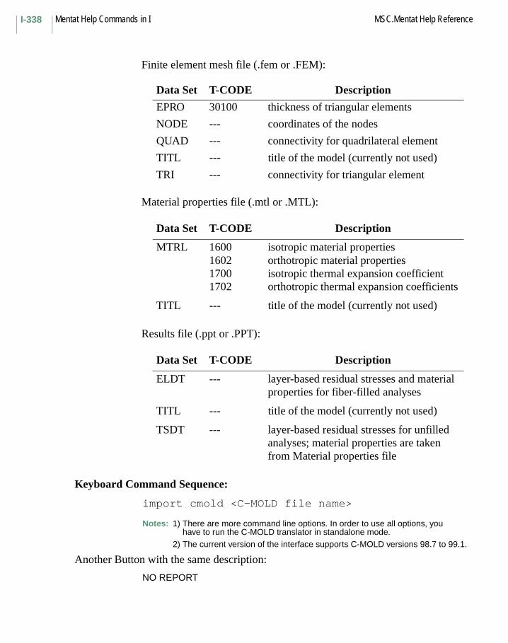
Mentat Help Commands in I MSC.Mentat Help ReferenceI-338
Finite element mesh file (.fem or .FEM):
Material properties file (.mtl or .MTL):
Results file (.ppt or .PPT):
Keyboard Command Sequence:
import cmold <C-MOLD file name>
Notes: 1) There are more command line options. In order to use all options, you have to run the C-MOLD translator in standalone mode.
2) The current version of the interface supports C-MOLD versions 98.7 to 99.1.
Another Button with the same description:
NO REPORT
Data Set T-CODE Description
EPRO 30100 thickness of triangular elements
NODE --- coordinates of the nodes
QUAD --- connectivity for quadrilateral element
TITL --- title of the model (currently not used)
TRI --- connectivity for triangular element
Data Set T-CODE Description
MTRL 1600160217001702
isotropic material propertiesorthotropic material propertiesisotropic thermal expansion coefficientorthotropic thermal expansion coefficients
TITL --- title of the model (currently not used)
Data Set T-CODE Description
ELDT --- layer-based residual stresses and material properties for fiber-filled analyses
TITL --- title of the model (currently not used)
TSDT --- layer-based residual stresses for unfilled analyses; material properties are taken from Material properties file

I-339MSC.Mentat Help Reference Mentat Help Commands in I
DXF/DWG
Command: import dxf
Description: This command imports an ASCII AutoCAD DXF file. You must specify the name of the file. There are four switches (or options) which you can control within Mentat. Here are the descriptions of the switches.
COLOR(S)This allows a particular color to be translated into Mentat. By default, ALL colors are translated.
LEVEL(S)This allows a particular level to be translated into Mentat. By default, ALL levels are translated.
TOLERANCEThis allows user to specify a tolerance for the input model. By default, tolerance is obtained from the input file.
REPORTThis allows user to create a summary report of the input file. Here are some of the goodies included in the report: DXF version number, DXF entity summary, warnings messages regarding bad entities in the DXF file, Mentat entity summary, etc.
Keyboard Command Sequence:
import dxf <AutoCAD file name>
Notes: 1) There are more command line options. In order to use all options, you will need to run the DXF translator in the standalone mode.
2) AutoCAD r13c4’s DXF is supported.
Other Buttons with the same description:
COLORS(S)DXFLAYER(S)NO REPORTTOLERANCE
DXF/DWG

Mentat Help Commands in I MSC.Mentat Help ReferenceI-340
I-DEAS
Command: import ideas <filename>
Description: This command imports information from Ideas-produced universal file. You must specify the name of the file. Messages generated during the import operation provide information about which data have been imported and about any errors that occur.
The element types (shapes) currently supported are:
Dataset 780
The apply types currently supported are:
mentatelement class ideas desc id
LINE2 11 21 22 23 122 171
LINE3 24 172
QUAD4 44 54 64 71 84 94 151 152
QUAD8 45 55 75 82 85 95
TRIA3 41 42 51 61 74 81 91
TRIA6 52 72 92
TETRA4 111
TETRA10 118
PENTA6 101 112
PENTA15 113
HEX8 115
HEX20 116
Dataset 755
restraint type
12
nodal displacementnodal temperature
Dataset 782
load type 13456
nodal forceelement face pressureelement face heat fluxelement edge pressureelement edge heat flux
I-DEAS

I-341MSC.Mentat Help Reference Mentat Help Commands in I
The material types currently supported are:
The geometry types currently supported are:
Dataset 773
material type
1123569
1018
isotropic indicesmodulus of elasticitypoisson’s ratiomass densitycoefficient thermal expansionthermal conductivityspecific heatyield stressemissivity
2101102103104105106
3108109110111112113114115116
9
orthotropic indicesmodulus of elasticity xmodulus of elasticity ymodulus of elasticity zpoisson’s ratio xypoisson’s ratio yzpoisson’s ratio zxmass densityshear modulus xyshear modulus yzshear modulus zxcoefficient thermal expansion xcoefficient thermal expansion ycoefficient thermal expansion zthermal conductivity xthermal conductivity ythermal conductivity zspecific heat
Dataset 788 or 772
physical prop.
only thickness
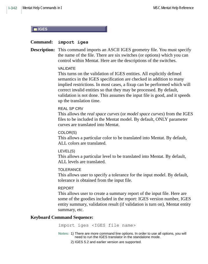
Mentat Help Commands in I MSC.Mentat Help ReferenceI-342
IGES
Command: import iges
Description: This command imports an ASCII IGES geometry file. You must specify the name of the file. There are six switches (or options) which you can control within Mentat. Here are the descriptions of the switches.
VALIDATEThis turns on the validation of IGES entities. All explicitly defined semantics in the IGES specification are checked in addition to many implied restrictions. In most cases, a fixup can be performed which will correct invalid entities so that they may be processed. By default, validation is not done. This assumes the input file is good, and it speeds up the translation time.
REAL SP CRVThis allows the real space curves (or model space curves) from the IGES files to be included in the Mentat model. By default, ONLY parameter curves are translated into Mentat.
COLOR(S)This allows a particular color to be translated into Mentat. By default, ALL colors are translated.
LEVEL(S)This allows a particular level to be translated into Mentat. By default, ALL levels are translated.
TOLERANCEThis allows user to specify a tolerance for the input model. By default, tolerance is obtained from the input file.
REPORTThis allows user to create a summary report of the input file. Here are some of the goodies included in the report: IGES version number, IGES entity summary, validation result (if validation is turn on), Mentat entity summary, etc.
Keyboard Command Sequence:
import iges <IGES file name>
Notes: 1) There are more command line options. In order to use all options, you will need to run the IGES translator in the standalone mode.
2) IGES 5.2 and earlier version are supported.
IGES
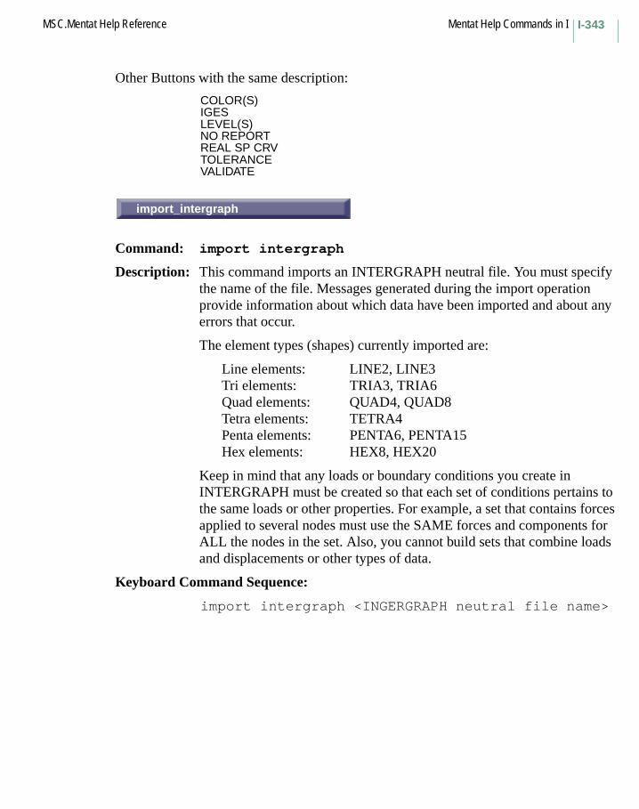
I-343MSC.Mentat Help Reference Mentat Help Commands in I
Other Buttons with the same description:
COLOR(S)IGESLEVEL(S)NO REPORTREAL SP CRVTOLERANCEVALIDATE
import_intergraph
Command: import intergraph
Description: This command imports an INTERGRAPH neutral file. You must specify the name of the file. Messages generated during the import operation provide information about which data have been imported and about any errors that occur.
The element types (shapes) currently imported are:
Line elements: LINE2, LINE3Tri elements: TRIA3, TRIA6Quad elements: QUAD4, QUAD8Tetra elements: TETRA4Penta elements: PENTA6, PENTA15Hex elements: HEX8, HEX20
Keep in mind that any loads or boundary conditions you create in INTERGRAPH must be created so that each set of conditions pertains to the same loads or other properties. For example, a set that contains forces applied to several nodes must use the SAME forces and components for ALL the nodes in the set. Also, you cannot build sets that combine loads and displacements or other types of data.
Keyboard Command Sequence:
import intergraph <INGERGRAPH neutral file name>
import_intergraph

Mentat Help Commands in I MSC.Mentat Help ReferenceI-344
MARC INPUT
Command: import marc_read
Description: This command reads a Marc input file into Mentat.
Note: On the console where the program was started, there should be some messages regarding the import process. In general, "exit number" 3025 means the .dat file has been imported successfully.
Keyboard Command Sequence:
import marc_read <MARC file name>
NASTRAN
Command: import nastran
Description: This command reads a NASTRAN neutral file. You must specify the NASTRAN file name.
Keyboard Command Sequence:
import nastran <NASTRAN file name>
PATRAN
Command: import patran
Description: This command imports a Patran neutral file. You must specify the name of the file. Messages generated during the import operation provide information about which data has been imported and about any errors that occur.
Packet Type 01: Node Data
This translator doesn’t read Coordinate Frame CID.
Packet Type 02: Element Data
The element types (shapes) currently imported are:
Line elements: LINE2, LINE3
MARC INPUT
NASTRAN
PATRAN

I-345MSC.Mentat Help Reference Mentat Help Commands in I
Tri elements: TRIA3, TRIA6Quad elements: QUAD4, QUAD8Tetra elements: TETRA4Penta elements: PENTA6, PENTA15Hex elements: HEX8, HEX20
Packet Type 03: Material properties
ISOTROPICyoungs_moduluspoissons_ratiothermal_expansionyield_stressspecific_heatmass_densityemissivityconductivity
ORTHOTROPICyoungs_modulus11youngs_modulus22youngs_modulus33poissons_ratio12poissons_ratio23poissons_ratio31shear_modulus12shear_modulus23shear_modulus31mass_densitythermal_exp11thermal_exp22thermal_exp33conductivity11conductivity22conductivity23specific_heat
Packet Type 04: Element Properties
Material ID is only available.
Packet Type 06: Distributed Loads
This is unsupported in case GFLAG=1.
Mentat Help Commands in I MSC.Mentat Help ReferenceI-346
Packet Type 07: Node Forces
Coordinate frame ID CID is unsupported.
Packet Type 08: Node Displacements
Coordinate frame ID CID is unsupported.
Packet Type 10: Node Temperatures
Packet Type 15: Nodal Heat Source
Packet Type 16: Distributed Heat Source
This is unsupported in case NFLAG=1.
Packet Type 17: Convection Coefficients
This is unsupported in case NFLAG=1.
Keyboard Command Sequence:
import patran (PATRAN neutral file name)
STL
Command: import stl
Description: This command imports an ASCII or BINARY Stereolithography Interface Format (STL) file into Mentat.
Current version is October 1989.
Keyboard Command Sequence:
import stl (STL file name)
STL

I-347MSC.Mentat Help Reference Mentat Help Commands in I
VDAFS
Command: import vda
Description: This command imports an ASCII VDAFS file. You must specify the name of the file. There are two switches (or options) which one can control within Mentat. Here are the descriptions of the switches.
TOLERANCEThis allows user to specify a tolerance for the input model. By default, tolerance is obtained from the input file.
REPORTThis allows user to create a summary report of the input file. Here are some of the goodies included in the report: VDA version number, VDA entity summary, validation result (if validation is turn on), Mentat entity summary, etc.
Keyboard Command Sequence:
import vda <VDAFS file name>
Notes: 1) There are more command line options. In order to use all options, you will need to run the VDA translator in the standalone mode.
2) VDAFS 2.0 and earlier version are supported.
Other Buttons with the same description:
NO REPORTREPORT FILETOLERANCE
VDAFS

Mentat Help Commands in I MSC.Mentat Help ReferenceI-348
INCREMENT HUE
Command: increment_hue
Description: This command interpolates the color hues used to show variations in increments for contour plotting and other graphical incremental indicators. You must specify the starting and ending color indices and the hue increment.
The two color indices will be used as the starting and ending values of a color interpolation that uses the specified hue increment.
Keyboard Command Sequence:
increment_hue <starting index> <ending index><hue increment>
INITIAL CONDITIONS
Menu: INITIAL CONDITIONS
Description: The INITIAL CONDITIONS menu contains commands that apply initial conditions to the mesh. Initial conditions may be applied for mechanical and heat transfer analysis types. The types of boundary conditions that can be applied depend on the type of analysis.
INITPL
Subroutine: INITPL
Description: The user subroutine INITPL is called in a loop over all the elements in the mesh when the INITIAL PLASTIC option appears in the model definition series with a 2 in column 10 of the second data block series of that option. It is often necessary to enter the amount of previously accumulated plastic strain. This initial value is only used in the work (strain) hardening calculation.
INCREMENT HUE
INITIAL CONDITIONS
INITPL

I-349MSC.Mentat Help Reference Mentat Help Commands in I
INITSV
Subroutine: INITSV
Description: The user subroutine INITSV allows you to define initial values of state variables. This routine will be called in a loop over all the elements in the mesh when the INITIAL STATE option appears in the model definition series with a 2 in column 10 of the second data block series of that option.
NAME
Command: insert_name
Description: This command sets or changes the name of the current insert.
Keyboard Command Sequence:
insert_name <insert name>
INTCRD
Subroutine: INTCRD
Description: The user subroutine INTCRD makes the integration point coordinates for the stiffness matrix available at each increment. You may save them in any form convenient for your postprocessing.
INITSV
NAME
INTCRD

Mentat Help Commands in I MSC.Mentat Help ReferenceI-350
HUE-LIGHTNESS-SATURATION CUBE
Command: interpolate_hls
Description: This command interpolates color values using hue, level, and saturation. The gray values and lighting properties for each color index are also interpolated. You must specify the first and last color indices between which colors are to be interpolated.
Keyboard Command Sequence:
interpolate_hls <first color index><last color index>
RED-GREEN-BLUE CUBE
Command: interpolate_rgb
Description: This command interpolates color values using red, green, and blue values. The gray values and lighting properties for each color index are also interpolated. You must specify the first and last color indices between which colors are to be interpolated.
Keyboard Command Sequence:
interpolate_rgb <first color index><last color index>
INTERSECT
Menu: INTERSECT
Description: This menu contains commands that intersect curves and surfaces.
HUE-LIGHTNESS-SATURATION CUBE
RED-GREEN-BLUE CUBE
INTERSECT

I-351MSC.Mentat Help Reference Mentat Help Commands in I
CURVE/CURVE
Command: intersect_curves
Description: This command finds all the intersections of the given list of curves. This command also breaks the curves at the intersection points.
Notice that trim curves can be intersected only with other trim curves of the same parent surface.
Keyboard Command Sequence:
intersect_curves <list of curves>
CURVE/SURFACE
Command: intersect_curves_surface
Description: This command finds all the intersections of the given list of curves against a surface. This command also breaks the curves at the intersection points.
Keyboard Command Sequence:
intersect_curves_surface<surface, list of curves>
CURVE/CURVE
CURVE/SURFACE
Mentat Help Commands in I MSC.Mentat Help ReferenceI-352
SURFACE/SURFACE
Command: intersect_surface
Description: This command generates the curve(s) of intersection of two surfaces. The surfaces are subdivided till they are flat enough to approximate the intersections by plane plane intersection. The resulting line segments are then stringed to get the intersection curves. For stringing line segments, the algorithm uses the sweep_tolerance for checking equality of 3-D points. If this tolerance is very small, the algorithm will return disconnected curve segments. This tolerance can be set using set_sweep_tolerance command.
For each intersection, in addition to the real space curve, the two parameter space curves are also returned as trim curves. The user can switch on or off any of these three curves. Notice that, if the trim curves from a closed loop in the parametric space, it affects the topology of the surface.
Keyboard Command Sequence:
intersect_surface <surface 1> <surface 2>
ALL
Command: invisible_all
Description: This command makes the all nodes, elements, points, curves, surfaces, and solids invisible.
Keyboard Command Sequence:
invisible_all
SURFACE/SURFACE
ALL
I-353MSC.Mentat Help Reference Mentat Help Commands in I
CURVES
Command: invisible_curves
Description: This command makes the specified curves invisible.
Keyboard Command Sequence:
invisible_curves <curve list> #
ELEMENTS
Command: invisible_elements
Description: This command makes the specified elements invisible.
Keyboard Command Sequence:
invisible_elements <element list> #
MAKE INVISIBLE
Command: invisible_selected
Description: This command causes the currently selected entities to be made invisible. Selected entities can be made visible with the visible_selected command.
Keyboard Command Sequence:
invisible_selected
CURVES
ELEMENTS
MAKE INVISIBLE

Mentat Help Commands in I MSC.Mentat Help ReferenceI-354
SOLIDS
Command: invisible_solids
Description: This command makes the specified solids invisible. Solids can be made visible with the visible_solids command.
Keyboard Command Sequence:
invisible_solids <solid list> #
SURFACES
Command: invisible_surfaces
Description: This command makes the specified surfaces invisible.
Keyboard Command Sequence:
invisible_surfaces <surface list> #
SOLIDS
SURFACES

Mentat Help Commands in JREM
Command: job_activate_elements
Description: This command activates elements that have been deactivated with the job_deactivate_elements command.
Keyboard Command Sequence:
job_activate_elements <element list> #
MAX. # ELEMENTS
Command: job_param max_eljob_param max_nod
Description: These commands set upper bounds to the number of elements and nodes that are allowed to be created during remeshing or adaptivity (element splitting).
MAX. # ELEMENTS upper bound for the number of elements
J Commands Begin with J
REM
MAX. # ELEMENTS
Mentat Help Commands in J MSC.Mentat Help ReferenceJ-356
MAX. # NODES upper bound for the number of nodes
The values are used for allocating memory for the analysis. The options STOP AT LIMIT and ALLOW MEMORY GROWTH are used to control if the analysis should stop when the maximum number is exceeded or if more memory should be allocated.
Reference: MSC.Marc Volume C: Program Input, Chapter 2: parameter ADAPTIVE
Keyboard Command Sequence:
job_param max_el <value>
Another Button with the same description:
MAX. # NODES
MAX. # CONTACT SEGMENT/BODY
Command: job_param max_cont_segjob_param max_cont_nod
Description: These commands set upper bounds to the number of segments and nodes on the boundary of any contact body that are allowed to be created during remeshing or adaptivity (element splitting).
MAX. # CONTACT SEGMENTS / BODY upper bound for the number of segments
MAX. # CONTACT NODES / BODY upper bound for the number of nodes
The values are used for allocating memory for the analysis. Larger values need to be specified for the remeshed bodies. Note that if zero values are specified, the memory allocation is based upon the initial mesh. If a mesh with more elements is to be created, larger values must be specified.
Reference: MSC.Marc Volume C: Program Input, Chapter 3: Model Definition CONTACT, 2nd data block, 2nd and 3rd parameters
Keyboard Command Sequence:
job_param max_cont_seg <value>job_param max_cont_nod <value>
MAX. # CONTACT SEGMENTS/BODY

J-357MSC.Mentat Help Reference Mentat Help Commands in J
STOP AND RESTART
Command: job_option rmsh_analysis
Description: This command determines the way the mesher is started during remeshing.
STOP AND RESTART The main analysis is stopped and the mesher is run. When the mesher is done the main analysis restarts, reads in the mesh information file from the mesher and continues.
WAIT The main analysis just halts while the mesher runs. On Windows, a system call is issued from the main analysis to run the mesher. On UNIX systems, a separate script is run that controls the running of the mesher.
The advantage with STOP AND RESTART is that the memory used by the main analysis is released so that the mesher can use more memory if needed. With the WAIT option, the main analysis and the mesher occupy memory at the same time. A disadvantage with STOP AND RESTART is that a potentially large restart file is written very increment.
Keyboard Command Sequence:
job_optionjob_option rmsh_analysis:<wait/stop_rstrt>
Another Button with the same description:
WAIT
STOP AND RESTART
Mentat Help Commands in J MSC.Mentat Help ReferenceJ-358
ALLOW MEMORY GROWTH
Command: job_option rmsh_limit
Description: This command defines whether the analysis should stop if the maximum number of elements or nodes is reached during remeshing.
STOP AT LIMIT stop the analysis if the maximum number of elements or nodes is reached
ALLOW MEMORY GROWTH allocate more memory if possible to be able to continue the analysis
Keyboard Command Sequence:
job_option rmsh_limit:<stop/grow>
Another Button with the same description:
STOP AT LIMIT
PROCEED (PREVIOUS MESH)
Command: job_option adap_proceed
Description: This command defines whether the analysis should stop if the maximum number of elements or nodes is reached during adaptivity (element splitting).
STOP AT LIMIT stop the analysis if the maximum number of elements or nodes is reached
PROCEED proceed the analysis using the previous mesh(PREVIOUS MESH)
Keyboard Command Sequence:
job_option adap_proceed:<on/off>
Another Button with the same description:
STOP AT LIMIT
ALLOW MEMORY GROWTH
PROCEED (PREVIOUS MESH)
J-359MSC.Mentat Help Reference Mentat Help Commands in J
ANALYSIS OPTIONS
Menu: ANALYSIS OPTIONS
Description: This popup menu contains commands for setting analysis options for the current job.
INCREMENTS
Command: job_buckle_increments
Description: This command specifies which increments a buckle analysis will be performed.
Keyboard Command Sequence:
job_buckle_increments <increment numbers>
CLEAR
Command: clear_job_buckle_increments
Description: This command clears the increments specified for buckle analysis.
Keyboard Command Sequence:
clear_job_buckle_increments
OFF
Command: job_option buckle_inc
Description: This command specifies if a buckling analysis with the BUCKLE INCREMENT option is to be performed.
This option allows you to specify at which increments a buckling analysis is performed. It is used as either a replacement to the BUCKLE loadcase option or in conjunction with it. This option allows you to extract modes within a loadcase with multiple increments. The increments are specified with the job_buckle_increments command under the BUCKLE
ANALYSIS OPTIONS
INCREMENTS
CLEAR
OFF
Mentat Help Commands in J MSC.Mentat Help ReferenceJ-360
INCREMENTS menu. Note that the increment numbers specified here cannot be changed upon restart.
The choice of buckle solution method is made with the buttons above. The specification of the number of modes to extract is done under JOBS->MECHANICAL->JOB PARAMETERS. The eigenvectors, stresses, and the reactions are automatically set to be printed out to the post file.
The option in Marc to perform a perturbation of the geometry by the buckling mode is not yet supported by Mentat and must be entered into the input file by the user.
Reference: MSC.Marc Volume C: Program Input, Chapter 3: Model Definition CONTACTMSC.Marc Volume A: Theory and User Information, Chapter 5
Keyboard Command Sequence: job_option buckle_inc:<on/off>
Another Button with the same description:ON
BUCKLE INCREMENTS
Menu: BUCKLE INCREMENTS
Description: This popup menu contains commands for specifying a buckling analysis with the BUCKLE INCREMENT option.
This option allows you to specify at which increments a buckling analysis is performed. It is used as either a replacement to the BUCKLE loadcase option or in conjunction with it. This option allows you to extract modes within a loadcase with multiple increments. Note that the increment numbers specified here cannot be changed upon restart.
The choice of buckle solution method is made with the buttons above. The specification of the number of modes to extract is done under JOBS->MECHANICAL->JOB PARAMETERS. The eigenvectors, stresses, and the reactions are automatically set to be printed out to the post file.
The option in Marc to perform a perturbation of the geometry by the buckling mode is not yet supported by Mentat and must be entered into the input file by the user.
Reference: MSC.Marc Volume C: Program Input, Chapter 3: model definition CONTACTMSC.Marc Volume A: Theory and User Information, Chapter 5
BUCKLE INCREMENTS
J-361MSC.Mentat Help Reference Mentat Help Commands in J
INVERSE POWER SWEEP
Command: job_option buckle_method
Description: This command specifies the method to be used to extract the buckling modes.
The inverse power sweep method is the default. The Lanczos method is usually more efficient, in particular for large models and when several modes are to be extracted. It also handles multiple eigenvalues better.
The specification of the number of buckling modes to extract is done under JOBS->MECHANICAL->JOB PARAMETERS. The eigenvectors, stresses and the reactions are automatically set to be printed out to the post file.
The option in Marc to perform a perturbation of the geometry by the buckling mode is not yet supported by Mentat and must be entered into the input file by the user.
Reference: MSC.Marc Volume A: Theory and User Information, Chapter 5
Keyboard Command Sequence:
job_option buckle_method:<power/lanczos>
Another Button with the same description:
LANCZOS
# BUCKLE MODES
Command: job_param buckle_nbmodesjob_param buckle_npbmodes
Description: These commands specify the number of buckling modes to be estimated.
The first command, job_param buckle_nbmodes, # BUCKLE MODES is used to specify the number of buckling modes to extract.
The second command, job_param buckle_npbmodes, # POS. BUCKLE MODES refers to the number of buckling modes with positive eigenvalues that is to be extracted.
In many buckling problems, collapse modes corresponding to loads of opposite magnitude to those of interest exist. With this option, you can
INVERSE POWER SWEEP
# BUCKLE MODES
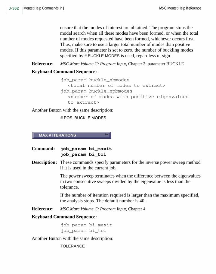
Mentat Help Commands in J MSC.Mentat Help ReferenceJ-362
ensure that the modes of interest are obtained. The program stops the modal search when all these modes have been formed, or when the total number of modes requested have been formed, whichever occurs first. Thus, make sure to use a larger total number of modes than positive modes. If this parameter is set to zero, the number of buckling modes specified by # BUCKLE MODES is used, regardless of sign.
Reference: MSC.Marc Volume C: Program Input, Chapter 2: parameter BUCKLE
Keyboard Command Sequence:
job_param buckle_nbmodes<total number of modes to extract>
job_param buckle_npbmodes<number of modes with positive eigenvalues to extract>
Another Button with the same description:
# POS. BUCKLE MODES
MAX # ITERATIONS
Command: job_param bi_maxitjob_param bi_tol
Description: These commands specify parameters for the inverse power sweep method if it is used in the current job.
The power sweep terminates when the difference between the eigenvalues in two consecutive sweeps divided by the eigenvalue is less than the tolerance.
If the number of iteration required is larger than the maximum specified, the analysis stops. The default number is 40.
Reference: MSC.Marc Volume C: Program Input, Chapter 4
Keyboard Command Sequence:
job_param bi_maxitjob_param bi_tol
Another Button with the same description:
TOLERANCE
MAX # ITERATIONS

J-363MSC.Mentat Help Reference Mentat Help Commands in J
MECHANICAL
Command: job_class
Description: This command sets the class of the current job to the specified class.
The valid job classes are as follows:
mechanicalheatcoupledjoule_heatingjoule_mechanicalelectrostaticpiezo_electricacousticacoustic_solidmagnetostaticelectromagneticfluidfluid_thermalfluid_solidfluid_thermal_solidbearing
Keyboard Command Sequence:
job_class
Other Buttons with the same description:
ACOUSTICACOUSTIC-SOLIDBEARINGCOUPLEDELECTROMAGNETICELECTROSTATICFLUIDFLUID-SOLIDFLUID-THERMALFLUID-THERMAL-SOLIDHEAT TRANSFERJOULE HEATINGJOULE MECHANICALMAGNETOSTATIC
MECHANICAL
Mentat Help Commands in J MSC.Mentat Help ReferenceJ-364
CLEAR
Command: job_clear_host_file
Description: Clears the current job’s host file.
Keyboard Command Sequence:
job_clear_host_file
CLEAR
Command: job_clear_scratch_directory
Description: Clears the current job’s scratch directory.
Keyboard Command Sequence:
job_clear_scratch_directory
CLEAR
Command: job_clear_usersub_file
Description: Clears the current job’s user subroutine file.
Keyboard Command Sequence:
job_clear_usersub_file
CONTACT CONTROL
Menu: CONTACT PARAMETERS
Description: This popup menu contains commands for setting contact job parameters for the current job.
CLEAR
CLEAR
CLEAR
CONTACT CONTROL

J-365MSC.Mentat Help Reference Mentat Help Commands in J
DISTANCE TOLERANCE BIAS
Command: job_param disttolbias
Description: Sets the contact bias factor for the current job.
This factor takes values between -1 and 1 and controls the position of the contact tolerance zone. By default, the bias factor is zero and the contact tolerance zone is symmetric around the contact entity. With a positive bias factor, the contact tolerance zone is moved into the body and thus providing a more accurate contact description.
Reference: MSC.Marc Volume C: Program Input, Chapter 3: Model Definition CONTACTMSC.Marc Volume A: Theory and User Information, Chapter 8
Keyboard Command Sequence:
job_param disttolbias <distance tolerance bias>
ALLOWED
Command: job_option chatter
Description: This command is used to specify whether a node that comes into contact in the current increment is allowed to separate again during the current increment.
Setting this to suppressed prevents chattering.
Reference: MSC.Marc Volume C:, Program Input, Chapter 3: Model Definition CONTACT
Keyboard Command Sequence:
job_option chatter:<allowed/suppressed>
Another Button with the same description:
SUPPRESSED
DISTANCE TOLERANCE BIAS
ALLOWED
Mentat Help Commands in J MSC.Mentat Help ReferenceJ-366
DISTANCE TOLERANCE
Command: job_param disttol
Description: Sets the contact distance tolerance for the current job.
This defines the size of the contact tolerance zone, i.e. the distance below which a node is considered touching a surface. The default value is 5% of the smallest element side in case of solid elements or 50% of the smallest beam or shell thickness. Note that the default values are based on all elements in the model.
Reference: MSC.Marc Volume C: Program Input, Chapter 3: Model Definition CONTACTMSC.Marc Volume A: Theory and User Information, Chapter 8
Keyboard Command Sequence:
job_param disttol <distance tolerance>
DOUBLE-SIDED
Command: job_option style:double
Description: This command specifies that a double-sided contact treatment should be used.
A lower-numbered contact body is first checked for contact with a higher-numbered contact body and then the other way around.
Reference: MSC.Marc Volume C: Program Input, Chapter 3: Model Definition CONTACT
Keyboard Command Sequence:
job_option style:double
DISTANCE TOLERANCE
DOUBLE-SIDED

J-367MSC.Mentat Help Reference Mentat Help Commands in J
FORCE
Command: job_option separation
Description: This command specifies if the criterion used to decide whether or not a node in contact should separate is force-based or stress-based:
Force-based separation:
Separation occurs when the tensile contact normal force on the node in contact becomes larger than the separation threshold force. This threshold force can be set by the user with the option job_param sepforce or by using a contact table. In the latter case, the separation threshold can be set per pair of contact bodies.
The separation threshold force is by default equal to the maximum residual force component.
Stress-based separation:
Separation occurs when the tensile contact normal stress on the node in contact becomes larger than the separation threshold stress. With stress-based separation, the following is available:
• Define relative or absolute checking:
If absolute testing is used, then the user can enter directly the separation threshold stress. If relative checking is used, then the user has to enter a factor and the separation threshold stress is defined by this factor times the maximum compressive contact normal stress. The option to set the method of checking is job_option sep_strs_measure.
• Define the method to derive the contact normal stress:
The contact normal stress can be obtained by either dividing the nodal force by the corresponding equivalent area or by extrapolating and averaging the integration point stress values. The second method cannot be used for shell elements and MSC.Marc will automatically switch to the first if necessary. Defining the method is done with the option job_option sep_strs_deriv.
The threshold value to be entered by the user, either a factor or a stress, is done via the option job_param sepstress or job_param rel_sepstress, or via a contact table. In the latter case, the separation threshold can be set per pair of contact bodies.
FORCE
Mentat Help Commands in J MSC.Mentat Help ReferenceJ-368
By default, separation occurs if the tensile contact normal stress becomes larger than 10 percent of the maximum compressive contact normal stress.
Stress-based separation has the advantage over force-based separation that it eliminates the influence of the element size. For true quadratic contact, only stress-based separation can be used, where the nodal stresses are determined by extrapolating and averaging integration point stress values.
Reference: MSC.Marc Volume C: Program Input, Chapter 3: Model Definition CONTACTMSC.Marc Volume A: Theory and User Information, Chapter 8
Keyboard Command Sequence:
job_option separation:<force or stress>
Another Button with the same description:
STRESS
COULOMB
Command: job_option frictype
Description: This command is used to specify the type of friction that is used in the current job.
NONE friction is not to be taken into account.
STICK-SLIP a true stick-slip model which models the transition from stick to slip accurately. The model uses the coulomb model of friction. The behavior can be controlled by three parameters below.
SHEAR a cohesive model of friction in which the friction stress is based upon the coefficient of friction and the equivalent von Mises stress in the material.
COULOMB an adhesive model of friction in which the friction stress is based upon the coefficient of friction and the normal stress at the surface.
SHEAR FOR ROLLING enhanced shear model.
COULOMB FOR ROLLING enhanced coulomb model.
COULOMB
J-369MSC.Mentat Help Reference Mentat Help Commands in J
The main difference between the models "FOR ROLLING" and without rolling is that the "FOR ROLLING" models use an improved estimate of the friction condition at the first cycle of an increment. The "FOR ROLLING" models are therefore recommended over the ones without "rolling", in particular for cases where there is a large difference between the absolute sliding velocity and the relative sliding velocity between two contacting bodies.
The extension "FOR ROLLING" has historical significance in that the improvements to the model were done initially for ring rolling simulations. However, the enhanced model shows improved accuracy and convergence also for other types of applications, like sheet forming and elastomer analysis.
For all models except the stick-slip model a parameter "relative sliding velocity" must be specified. It is typically set to 1%-10% of the relative sliding velocity between contacting bodies. Note that it has the unit of length over time and that the default value of 1.0 is in general inappropriate.
For the coulomb and coulomb for rolling models there is the choice between having the friction based on nodal stress or nodal force. An exception is for shell elements where nodal force is always used. The stick-slip model always uses nodal force and the shear model nodal stress.
Reference: MSC.Marc Volume A: Theory and User Information, Chapter 8.
Keyboard Command Sequence:
job_option frictype:<none/coul_stick_slip/shear/coulomb/shear_roll/coulomb_roll>
Other Buttons with the same description:
COULOMB FOR ROLLINGNONESHEARSHEAR FOR ROLLINGSTICK-SLIP
NODAL FORCE
Command: job_option fricmeth
NODAL FORCE
Mentat Help Commands in J MSC.Mentat Help ReferenceJ-370
Description: This command is used to define if the friction model is based on nodal force or nodal stress.
See the help menu on the different friction types above for applicability.
Reference: MSC.Marc Volume A: Program Input, Chapter 8.
Keyboard Command Sequence:
job_option fricmeth:<nstress/nforce>
Another Button with the same description:
NODAL STRESS
RELATIVE SLIDING VELOCITY
Command: job_param vsliding
Description: This command is used to enter the relative sliding velocity that is used by all friction models except the stick-slip model.
This parameter controls the transition from stick to slip in these models. It is typically set to 1%-10% of the relative sliding velocity between contacting bodies.
Note that it has the unit of length over time and the default value of 1.0 is in general inappropriate. A value too small leads to convergence problems in the solution and a value too large gives inaccurate friction description.
Reference: MSC.Marc Volume A: Theory and User Information, Chapter 8.
Keyboard Command Sequence:
job_param vsliding <relative sliding velocity>
FRICTION COEFF. MULTIPLIER
Command: job_param stick_slip_transjob_param fric_coeff_multjob_param fric_force_tol
RELATIVE SLIDING VELOCITY
FRICTION COEFF. MULTIPLIER

J-371MSC.Mentat Help Reference Mentat Help Commands in J
Description: These commands are used to define the properties of the stick-slip models. Usually, the default values are appropriate. See the manual reference for details.
Reference: MSC.Marc Volume A: Theory and User Information, Chapter 8
Keyboard Command Sequence:
job_param stick_slip_trans <new value>job_param fric_coeff_mult <new value>job_param fric_force_tol <new value>
Other Buttons with the same description:
FRICTION FORCE TOLERANCESLIP TO STICK TRANS. REGION
GENUINE
Command: job_option quadr_cont_seg:genuine
Description: If the model contains a deformable or heat transfer rigid body with quadratic elements, then this command activates a boundary description based on the complete quadratic geometry. This implies that the mid-side nodes are fully taken into account: they can come into contact, and the patch they correspond to is described using a complete quadratic field.
Keyboard Command Sequence:
job_option quadr_cont_seg:genuine
INITIAL CONTACT
Menu: INITIAL CONTACT
Description: This menu contains commands for activating initial contact conditions: contact table, contact areas, and exclude segments.
LINEARIZED
Command: job_option quadr_cont_seg:linearized
GENUINE
INITIAL CONTACT
LINEARIZED

Mentat Help Commands in J MSC.Mentat Help ReferenceJ-372
Description: If the model contains a deformable or heat transfer rigid body with quadratic elements, then this command activates a boundary description based on a linearized geometry. This implies that the mid-side nodes are not treated independently: they cannot come into contact, and the geometry of the patch they correspond to is described using the corner nodes only. In a contact stress analysis this may result in strange stress concentrations in the contact area.
Keyboard Command Sequence:
job_option quadr_cont_seg:linearized
MAX # SEPARATIONS/INCREMENT
Command: job_param maxsep
Description: This command is used to define the maximum number of separations that can occur during an increment.
Each time a node is found to separate, the increment is recycled. This parameter limits the number of times that will occur. The default number is 9,999.
Reference: MSC.Marc Volume C: Program Input, Chapter 3: Model Definition CONTACT
Keyboard Command Sequence:
job_param maxsep <max. number of separations>
SEPARATION STRESS
Command: job_param rel_sepstress
Description: This command is used to specify the relative separation stress to be used instead of the default value.
Also see help: job_option separation.
Keyboard Command Sequence:
MAX # SEPARATIONS/INCREMENT
SEPARATION STRESS
J-373MSC.Mentat Help Reference Mentat Help Commands in J
job_param rel_sepstress<relative separation stress>
FORCE
Command: job_option separation
Description: This command specifies if the criterion used to decide whether or not a node in contact should separate is force-based or stress-based:
• Force-based separation:Separation occurs when the tensile contact normal force on the node in contact becomes larger than the separation threshold force. This threshold force can be set by the user with the option job_param sepforce or by using a contact table. In the latter case, the separation threshold can be set per pair of contact bodies.
By default, the separation threshold force is equal to the maximum residual force component.
• Stress-based separation:Separation occurs when the tensile contact normal stress on the node in contact becomes larger than the separation threshold stress. With stress-based separation, the following is available:
– Define relative or absolute checking:
If absolute testing is used, then the user can enter directly the separation threshold stress. If relative checking is used, then the user has to enter a factor and the separation threshold stress is defined by this factor times the maximum compressive contact normal stress. The option to set the method of checking is job_option sep_strs_measure.
FORCE

Mentat Help Commands in J MSC.Mentat Help ReferenceJ-374
– Define the method to derive the contact normal stress:
The contact normal stress can be obtained by either dividing the nodal force by the corresponding equivalent area or by extrapolating and averaging the integration point stress values. The second method cannot be used for shell elements and Marc will automatically switch to the first if necessary. Defining the method is done with the option job_option sep_strs_deriv.
The threshold value to be entered by the user, either a factor or a stress, is done via the option job_param sepstress or job_param rel_sepstress, or via a contact table. In the latter case, the separation threshold can be set per pair of contact bodies.
By default, separation occurs if the tensile contact normal stress becomes larger than 10 percent of the maximum compressive contact normal stress.
Stress-based separation has the advantage over force-based separation that it eliminates the influence of the element size. For true quadratic contact, only stress-based separation can be used, where the nodal stresses are determined by extrapolating and averaging integration point stress values.
Reference: MSC.Marc Volume C: Program Input, Chapter 3: Model Definition Option, CONTACT.MSC.Marc Volume A: Theory and User Information, Chapter 8.
Keyboard Command Sequence:
job_option separation:<force/stress>
Other Buttons with the same description:
STRESS
SEPARATION FORCE
Command: job_param sepforce
Description: This command is used to specify the separation force to be used instead of the default value.
Also see help: job_option separation.
Keyboard Command Sequence:
SEPARATION FORCE

J-375MSC.Mentat Help Reference Mentat Help Commands in J
job_param sepforce <separation force>
Mentat Help Commands in J MSC.Mentat Help ReferenceJ-376
CURRENT
Command: job_option sepinc
Description: This command is used to specify when separation should actually occur.
When a separation is detected, the bodies are separated either in the current increment or in the next. The latter option may lead to decreased computational cost but lower the accuracy of the solution.
Reference: MSC.Marc Volume C: Program Input, Chapter 3: Model Definition, CONTACT
Keyboard Command Sequence:
job_option sepinc:<current/next>
Another Button with the same description:
NEXT
SEPARATION STRESS
Command: job_param sepstressjob_param rel_sepstress
Description: This command is used to specify the separation stress (sepstress) or relative separation stress (rel_sepstress) to be used instead of the default value. The type that is used is dependent on whether the job_option sepstrs_measure is specified as absolute or relative (the button ABSOLUTE/RELATIVE located adjacent to this button.
Also see help: job_option separation and job_option sep_strs_measure.
Reference: MSC.Marc Volume C: Program Input, Chapter 3: Model Definition CONTACTMSC.Marc Volume A: Theory and User Information, Chapter 8.
Keyboard Command Sequence:
job_param sepstress <separation stress>job_param rel_sepstress
<relative separation stress>
CURRENT
SEPARATION STRESS

J-377MSC.Mentat Help Reference Mentat Help Commands in J
FORCE/AREA
Command: job_option sep_strs_deriv
Description: For stress-based separation, this command is used to specify the way in which the contact normal stress is derived; this can be either done by dividing the contact normal force by the equivalent area or by extrapolating and averaging integration point stress values.
Also see help: job_option separation.
Keyboard Command Sequence:
job_option sep_strs_deriv:<force_area/extrapolation>
Another Button with the same description:
EXTRAPOLATION
ABSOLUTE
Command: job_option sep_strs_measure
Description: For stress-based separation, this command is used to specify that separation has to be based on either absolute or relative checking.
Also see help: job_option separation.
Keyboard Command Sequence:
job_option sep_strs_measure:<absolute/relative>
Another Button with the same description:
RELATIVE
FORCE/AREA
ABSOLUTE

Mentat Help Commands in J MSC.Mentat Help ReferenceJ-378
CHECK TOP & BOTTOM SURFACE
Command: job_option checkshell
Description: This command is used to specify the contact treatment for shell elements.
CHECK TOP & BOTTOM SURFACE contact is detected with either side of the surface and the shell thickness is always taken into account.
CHECK TOP SURFACE contact is only detected with the top surface of the shell. The top surface is in the positive direction of the shell normal.
CHECK BOTTOM SURFACE contact is only detected with the bottom surface of the shell. The bottom surface is in the negative direction of the shell normal.
The choice of taking the shell thickness into account for the latter two options is made with the command job_option ignore: on/off (menu IGNORE THICKNESS).
The orientation of the elements is visualized with the command identify_backfaces under:
CONTACT->CONTACT BODIES->ID BACKFACES(turn off with identify_none).
By default, the top surface is plotted in blue. Shell normals of connected elements are aligned with the command align_shells under:
MESH GENERATION->CHECK->ALIGN SHELLS.
Reference: MSC.Marc Volume A, Theory and User Information, Chapter 8.
Keyboard Command Sequence:
job_option checkshell:<top/bottom/both>
Other Buttons with the same description:
CHECK TOP SURFACECHECK BOTTM SURFACE
CHECK TOP & BOTTOM SURFACE

J-379MSC.Mentat Help Reference Mentat Help Commands in J
SINGLE-SIDED
Command: job_option style:single
Description: This command specifies that a single-sided contact treatment should be used.
A lower-numbered contact body is only checked for contact with a higher-numbered contact body. Compared with the double-sided version, this leads to decreased cost for cases where one knows that a one-way treatment is appropriate.
Reference: MSC.Marc Volume C: Program Input, Chapter 3: Model Definition, CONTACT
Keyboard Command Sequence:
job_option style:single
END OF INCREMENT
Command: job_option split
Description: This command defines the method used to avoid that nodes might penetrate into a contact body. The possible options are:
END OF INCREMENT:At the end of each increment, a check is performed on nodes not being in contact at the beginning of the increment. If such a node has penetrated into a contact body beyond the contact tolerance zone, the increment is split in two parts. The first part is a linear scaling of the solution found so far, where the scaling factor is based on the node with the largest relative amount of penetration. The second part will finish the increment with one or more additional nodes in contact. If necessary, this process will be repeated.
PER ITERATION:After the incremental solution in the Newton-Raphson iteration process has been found, a check is performed if this iterative displacement vector will cause nodes to come into contact or to penetrate beyond the contact tolerance. If the latter is the case, the iterative displacement vector will be scaled such that no penetration will occur. Although this checking per iteration is more expensive than checking per increment, it is in general more reliable and accurate.
SINGLE-SIDED
END OF INCREMENT

Mentat Help Commands in J MSC.Mentat Help ReferenceJ-380
NONE:The penetration of a node is ignored in the current increment. Although this leads to decreased computational costs, it also leads to decreased accuracy and should normally not be used.
Reference: MSC.Marc Volume A: Theory and User Information, Chapter 8
Keyboard Command Sequence:
job_option split:<allowed/iterative/suppressed>
Other Buttons with the same description:
OFFPER ITERATION
job_contact_table
Command: job_contact_table
Description: This command is used to specify the contact table to be used initially for this job.
Other contact tables can be activated in each loadcase.
Keyboard Command Sequence:
job_contact_table <contact table name>
IGNORE THICKNESS
Command: job_option ignore
Description: This command is used to specify if thickness is to be taken into account for shell elements.
It is only applicable when contact is detected with the top or bottom surface.
Reference: MSC.Marc Volume A: Theory and User Information, Chapter 8
Keyboard Command Sequence:
job_option ignore:<on/off>
job_contact_table
IGNORE THICKNESS

J-381MSC.Mentat Help Reference Mentat Help Commands in J
CONVECTIVE TERMS
Command: job_option convective
Description: This command is used to activate or deactive the option of using a formulation with convection in a heat transfer analysis.
The general convection-diffusion equation is used in this case and its solver using the SUPG method.
This formulation requires that the velocity field is known, either by prescribing it or by using a thermomechanical coupled analysis with the rigid plastic flow option.
Reference: MSC.Marc Volume A, Theory and User Information, Chapter 7: Heat Transfer with Convection.
Keyboard Command Sequence:
job_option sep_strs_deriv:<force_area/extrapolation>
CUTTER FILE
Menu: CUTTER FILE
Description: This popup menu enables to specify the name of the cutter file.
CUTTER FILE
Command: job_cutter_file_name
Description: This entry box enables to specify the name of the cutter file.
Keyboard Command Sequence:
job_cutter_file <file_name>
CONVECTIVE TERMS
CUTTER FILE
CUTTER FILE

Mentat Help Commands in J MSC.Mentat Help ReferenceJ-382
CYCLIC SYMMETRY
Menu: CYCLIC SYMMETRY
Description: This popup menu automatically contains commands for taking cyclic symmetry conditions into account in the current job.
# REPETITIONS
Menu: CYCLIC SYMMETRY PARAMETERS
Description: This menu contains commands for automatically taking cyclic symmetry conditions into account in the current job. These conditions allow rotationally periodic structures to be analyzed by modeling only one segment of the complete structure. The user has to specify the axis around which the structure is rotationally periodic and the number of times the segment fits in the complete structure (i.e. the number of periods in the full 360 degree range). MSC.Marc will automatically detect the nodes that lie on the boundaries of the segment and create the proper constraint equations for these nodes. The meshes at these boundaries do not have to match.
If contact is used in the model, the elements along the cyclic symmetry boundaries must belong to the same contact body.
CYCLIC SYMMETRYWhen switched on, cyclic symmetry conditions are taken into account in the current job.
AXIS OF ROTATIONThe axis of rotation is defined by specifying its DIRECTION and a POINT on the axis.
# REPETITIONSThe number of times the segment fits in the complete structure.
AUTOMATIC SUPPRESSION OF ROTATIONAL RIGID BODY MOTIONWhen switched on, Marc will automatically suppress the rotational rigid body motion of the segment around the axis of rotation. For two-dimensional analyses, this is sufficient to eliminate all rigid body motions. For three-dimensional analyses, boundary conditions still have to be created to suppress the rigid body motion in the direction of the axis of rotation.
CYCLIC SYMMETRY
# REPETITIONS

J-383MSC.Mentat Help Reference Mentat Help Commands in J
Keyboard Command Sequence: job_option cyc_symm_rot:on|offjob_param cycs_rot_axis_dir_x <x_component_of_direction>job_param cycs_rot_axis_dir_y <y_component_of_direction>job_param cycs_rot_axis_dir_z <z_component_of_direction>
job_param cycs_rot_axis_point_x <x_component_of_point>job_param cycs_rot_axis_point_y <y_component_of_point>job_param cycs_rot_axis_point_z <z_component_of_point>
job_param cycs_rot_nrepetitions <number_of_repetitions>
job_param cycs_rot_rigb_supp:automatic|off
Reference: MSC.Marc Volume A: Theory and User Information, Chapter 9: Section Kinematic Constraints MSC.Marc Volume C: Program Input, Chapter 3: Model Definition Option CYCLIC SYMMETRY
Other Buttons with the same description:AUTOMATIC SUPPRESSIONCYCLIC SYMMETRYXYZ
MODE 1
Command: job_damping
Description: This command is used to specify the damping coefficients for each mode in a dynamic analysis.
Keyboard Command Sequence:
job_damping <mode number> <damping coefficient>
Other Buttons with the same description:
MODE 2...
MODE 30
MODE 1
Mentat Help Commands in J MSC.Mentat Help ReferenceJ-384
HOSTNAME
Command: job_dcom_hostname <name>
Description: This command specified the DCOM server to be used for Marc.
It is only available for Windows.
If the DCOM option is on, then this command is enabled to allow a server hostname to be specified to run the job remotely. It is independent of the parallel (USE DDM) option, and does not support multiple domains.
To use this option, you MUST ensure that:
• The machine that is specified as the host must be enabled as a Marc DCOM server.
• Your datafiles are on shared directories.• Your username/password is the same as for the host.
Keyboard Command Sequence:
job_dcom_hostname <name>
ADD
Command: job_deactivate_elements
Description: This command deactivates elements for the current job. Deactivated elements do not participate in the analysis.
Keyboard Command Sequence:
job_deactivate_elements <element list> #
HOSTNAME
ADD
J-385MSC.Mentat Help Reference Mentat Help Commands in J
METIS BEST
Command: job_option decomposition
Description: This command choose type of domain decompostion algorithm.
Keyboard Command Sequence:
job_option decomposition:<metis_best/ metis_element_based/ metis_node_based/ geometric/ simple>
Other Buttons with the same description:
METIS ELEMENT BASEDMETIS NODE BASEDGEOMETRICSIMPLE
metis_best performs metis element based and node based decomposition and picks the better solution.
metis_element_based
performs metis element based decomposition.
metis_node_based performs metis node based decomposition.
geometric performs decomposition based on coordinates (previously decompose) algorithm tries to anneal domains.
simple performs decomposition based on coordinates of element centroids (previously generate)
METIS BEST
Mentat Help Commands in J MSC.Mentat Help ReferenceJ-386
DESIGN
Command: N/A
Description: This button brings up the popup menu for:
a) setting either design SENSITIVITY or design OPTIMIZATION as the requested procedure.
b) defining the DESIGN OBJECTIVE
c) selecting the design variables (from the set already defined) which apply to this particular job and
d) determining the optional switches (2 each) for the selected procedure type.
MAX ACTIVE SET SIZE
Command: job_param des_act_cons
Description: This optional button allows the user to specify the maximum size of the active set of constraints during design optimization. The desired number is then entered in the dialogue area. If this button is not used, the default value of 100 is taken. The use of this button properly prevents a very high number of constraints (say a hundred-thousand) being dealt within the active set. All constraints are still evaluated, and the entries in the active set change dynamically.
COST
Command: job_option des_sen_object:cost
Description: This button appears when SENSITIVITY or OPTIMIZATION has been pressed. By pressing this button, the user specifies the objective function to be the total cost of the structure represented by the finite element model. In this case, it is necessary that the material data contain the unit cost of the materials (per unit volume or per unit mass as appropriate).
DESIGN
MAX ACTIVE SET SIZE
COST

J-387MSC.Mentat Help Reference Mentat Help Commands in J
# CRITICAL
Command: job_param des_crit_cons
Description: This button lights up only when the SORT CONSTRAINTS button has been pressed ON. It allows the user to specify in the dialog area, the number of most critical constraints for which sensitivity analysis is to be performed, thereby, overriding the default of 100. See also the help button for SORT CONSTRAINTS.
MASS
Command: job_option des_sen_object:mass
Description: This button appears when SENSITIVITY or OPTIMIZATION has been pressed. By pressing this button, the user specifies the objective function to be the total mass of the structure as represented by the finite element model. In this case, it is necessary that the material data contain the unit mass of the materials.
MAX CYCLES
Command: job_param des_opt_cycles
Description: This optional button allows the user to change the maximum allowable number of design optimization cycles up or down from its default value of 20. By setting a reasonable number of cycles for a substantially large problem, the time spent is reduced with possibly a sacrifice in how much better the design can be improved. The number of cycles is entered in the dialog area after the button is pressed.
# CRITICAL
MASS
MAX CYCLES
Mentat Help Commands in J MSC.Mentat Help ReferenceJ-388
OFF
Command: job_option design:off
Description: If design SENSITIVITY or design OPTIMIZATION was previously selected, pressing this OFF button will turn off the previous selection.
OPTIMIZATION
Command: job_option design:optimization
Description: This button selects DESIGN OPTIMIZATION as the job type. When this button becomes is pressed, the appropriate selections for DESIGN OBJECTIVE will appear along with the MAX ACTIVE SET SIZE and MAX CYCLES options (switches) which may be used with the DESIGN OPTIMIZATION parameter.
SENSITIVITY
Command: job_option design:sensitivity
Description: This button selects DESIGN SENSITIVITY analysis as the job type. When this button is pressed, the appropriate selections for DESIGN OBJECTIVE will appear along with the SORT CONSTRAINTS and CRITICAL options (switches) which may be used with the DESIGN SENSITIVITY parameter.
VOLUME
Command: job_option des_sen_object:volume
Description: This button appears when SENSITIVITY or OPTIMIZATION has been pressed. By pressing this button, the user specifies the objective function to be the total volume of the structure as represented by the finite element model.
OFF
OPTIMIZATION
SENSITIVITY
VOLUME

J-389MSC.Mentat Help Reference Mentat Help Commands in J
NONE
Command: job_option des_sen_object:none
Description: This button appears only when SENSITIVITY has been pressed. The user has the option of obtaining sensitivity information regarding the objective function by entering the type of objective function. Pressing this OFF button will result in no objective function being selected and the sensitivity analysis being limited to design constraints only.
<design variables name>
Command: job_add_desvar)job_remove_desvar)
Description: This command, located in the JOBS->MECHANICAL->DESIGN menu, will toggle between the ON and OFF phases of the button. ON corresponds to the related design variable being defined for the current job. OFF corresponds to the related design variable not being associated with the current job.
Keyboard Command Sequence:
job_add_desvarjob_remove_desvar
CLEAR
Command: clear_job_desvars
Description: Pressing this button clears any design variables which may have been assigned to the current job. The buttons for any assigned variables (the relevant buttons turned on) will be turned off as a result.
NONE
<design variable name>
CLEAR
Mentat Help Commands in J MSC.Mentat Help ReferenceJ-390
EDIT
Command: job_edit_host_file
Description: This command opens an edit window for the selected host file for the current job.
Keyboard Command Sequence:
job_edit_host_file
EDIT INPUT
Command: job_edit_input
Description: This command opens an edit window for the input file for the current job. The command determines the name of the file using the current model and job names.
Note that this command does not write the input file so this command must either be issued after the job is run or use the WRITE INPUT command first.
Keyboard Command Sequence:
job_edit_input
LOG FILE
Command: job_edit_log_file
Description: This command opens an edit window for the log file for the current job, and determines the name of the file using the current model and job names.
Keyboard Command Sequence:
job_edit_log_file
EDIT
EDIT INPUT
LOG FILE

J-391MSC.Mentat Help Reference Mentat Help Commands in J
OUTPUT FILE
Command: job_edit_output
Description: This command opens an edit window for the output file for the current job, and determines the name of the file using the current model and job names.
Keyboard Command Sequence:
job_edit_output
EDIT
Command: job_edit_usersub_file
Description: This command opens an edit window for the selected user subroutine file for the current job.
Keyboard Command Sequence:
job_edit_usersub_file
COMPATIBLE
Command: job_option network_hosts
Description: This option is used for defining if the machines connected in the network run are compatible or not. This is only relevant if user subroutines are used. If a user subroutine is used and the connected machines are not compatible (i.e. if any remote host cannot run the executable created on the parent host), the user subroutine is compiled on each connected machine and the new executable is given a unique name. This is handled by the Marc run script automatically.
The connection of incompatible machines is only possible on machines using the UNIX operative system in this release. A restriction is that Compaq/DEC machines cannot be connected to other UNIX machines.
OUTPUT FILE
EDIT
COMPATIBLE

Mentat Help Commands in J MSC.Mentat Help ReferenceJ-392
Keyboard Command Sequence:
job_option network_hosts:<compatible/incompatible>
Another Button with the same description:
INCOMPATIBLE
COPY INPUT FILE
Command: job_option copy_input_filejob_option copy_post_file
Description: These options are used to automatically copy input files to the remote hosts if necessary before the job starts and to copy the post files from the remote hosts back to the parent host after the job is finished.
COPY INPUT FILE if on, copy the input files to the remote hostsCOPY POST FILE if on, copy the post files back to the parent host
Keyboard Command Sequence:
job_option copy_input_file <on/off>job_option copy_post_file <on/off>
Another Button with the same description:
COPY POST FILE
HOST FILE
Command: job_host_file
Description: This command specifies the name of the host file for a parallel job over a network of computers. The host file contains information on which machines to use in the run, how many processes to use on each and where the working and installation directories are. The user is responsible for editing this file and providing the necessary information.
No particular name or file extension is used for the host file. Avoid the name jobname.host, where jobname is the name of the current job, since this file is created automatically when the job is run. (If the
COPY INPUT FILE
HOST FILE
J-393MSC.Mentat Help Reference Mentat Help Commands in J
model name is model1 and the current job name is job1, the name to avoid is model1_job1.host).
For each host (computer) used in the analysis, there is one line in the host file. Lines starting with # and blank lines are ignored. Each line must start at column 1. The general format is
host1 n1host2 n2 workdir2 marcdir2host3 n3 workdir3 marcdir3
This defines the three hosts host1, host2, and host3 to be part of the analysis. host1 uses n1 processors, host2 n2 and host3 n3 processors. The sum n1+n2+n3 must be equal to the number of domains used. host1 is the machine on which the job is started. workdir2 is the working directory for host2. This is where the input files for this host must be and where the results files are created. marcdir2 is the Marc installation directory that host2 is using. If workdir and marcdir are not specified for a host, it is assumed to be the same as for the parent host (host1). If marcdir is specified, workdir also needs to be specified.
Suppose n1=n2=n2=2. The domains 1 and 2 are run on host1, 3 and 4 on host2 and 5 and 6 on host3.
The directories given are as seen from that host. Suppose the working directory on host1 is called /users/smith (Windows: C:\users\smith). Suppose that directory is also to be used on host2 and can be accessed as /nfs/host1/users/smith (Windows: \\host1\cusers\smith) from host2. On Windows, "cusers" is the UNC sharename for the directory C:\users (the name given in the sharing setting). Similarly for the install dir suppose Marc is installed in /users/marc/marc2 (C:\users\marc\marc2) on host1. The host file would be, with one process on each host:
host1 1host2 1 /nfs/host1/users/smith /nfs/host1/users/marc/marc2Windows: host2 1 \\host1cusers\smith \\host1cusers\marc\marc2
If local directories are used on the remote host (host2), this can be specified as:
host1 1host2 1 /users/jones /users/marcinstall/marc2Windows: host2 1 f:\users\jones c:\marc\marc2
In this case, the input file for domain 2 needs to be transferred over to /users/jones on host2 and the results file needs to be transferred back for postprocessing of the whole model. This is done automatically if the
Mentat Help Commands in J MSC.Mentat Help ReferenceJ-394
COPY DAT FILE and COPY POST FILE options are activated. By default, all files are copied if necessary.
If user subroutines are used, the user subroutine is compiled and made available on all hosts automatically. If different types of UNIX machines are connected, the user subroutine is compiled on each host and the new executable is given a unique name if the working directory is shared.
Keyboard Command Sequence:
job_host_file <file name>
HYPERMESH
Menu: HYPERMESH (with solid mechanics or coupled type analyses)
Command: N/A
Description: Pressing this button will lead the user to the HyperMesh related menu for assigning the results which are to be written into the HyperMesh results file after the Marc analysis for a solid mechanics or coupled type (including solid mechanics) job.
HYPERMESH
Menu: HYPERMESH (with nonsolid mechanics type analyses, e.g. heat transfer)
Command: N/A
Description: Pressing this button will lead the user to the HyperMesh related menu for assigning the results which are to be written into the HyperMesh results file after the Marc analysis for a nonsolid mechanics type job.
HYPERMESH
HYPERMESH
J-395MSC.Mentat Help Reference Mentat Help Commands in J
MANUAL
Command: job_option inactive_elements
Menu: JOBS
Description: This option is used to specify the type of input of inactive elements.
If manual is selected, user can manually select inactive elements using Add/Remove.
If import is selected, user can specify the name of the file that contains the cutter path information.
Two types of the cutter path data are supported here:
APT source: Cutter path data output by CATIA. This file must have extension .apt.
CL file: Cutter path data output by APT compilers. This file must have extension .ccl.
Notes: 1. The cutter path file must reside in the job directory.
2. If no extension for the file name is given, MSC.Marc program will add the extensions: .apt or .ccl, automatically.
Keyboard Command Sequence:
job_option inactive_elements:<manual/import>
Another Button with the same description:
IMPORT
INITIAL LOADS
Menu: INITIAL LOADS
Description: This popup menu contains commands for selecting initial boundary condition applications (loads) for the current job.
MANUAL
INITIAL LOADS

Mentat Help Commands in J MSC.Mentat Help ReferenceJ-396
ASSUMED STRAIN
Command: job_option assumedstrn
Description: This option causes the assumed strain formulation to be used by the elements in the model that support it.
The bending behavior can be improved by using the assumed strain formulation for elements type 3 (plane stress), type 11 (plane strain), and type 7 (3-D brick). This procedure replaces the standard bi- or trilinear interpolation functions with an enriched group that is able to represent pure bending behavior. This formulation results in improved accuracy for isotropic behavior, but it should be noted that the computational costs increase.
Alternatively, this formulation can be applied to specified elements through the commands under the GEOMETRIC PROPERTIES menu.
Keyboard Command Sequence: job_option assumedstrn:<on/off>
CONSTANT DILATATION
Command: job_option cdilatation
Description: This option causes the constant dilatation option to be used by the elements in the model that support it.
When performing nearly incompressible analysis with displacement based elements, the conventional isoparametric interpolation methods result in poor behavior for lower order elements. This results in overly stiff behavior when using element type 7 (3-D brick), type 10 (axisymmetric), type 11 (plane strain), type 19 (generalized plane strain), or type 20 (axisymmetric with twist). When this option is included, all elements of these types are modified to use the constant dilatation formulation (also known as the mean dilatation or B-bar formulation). This is recommended for elastic-plastic analysis and creep analysis because of the potentially near incompressibility behavior.
Alternatively, this formulation can be applied to specified elements through the commands under the GEOMETRIC PROPERTIES menu.
Keyboard Command Sequence: job_option cdilatation:<on/off>
ASSUMED STRAIN
CONSTANT DILATATION

J-397MSC.Mentat Help Reference Mentat Help Commands in J
LINEAR ELASTIC ANALYSIS
Command: job_option elastic
Description: This command is used for specifying if a linear elastic analysis with several load cases is to be performed.
If this option is turned on, all loadcases are treated independently. All loads must then be given as total values as opposed to incremental values when a nonlinear analysis is performed. The assembled and decomposed stiffness matrices are used in all load cases, so make sure to use a direct solver.
The decomposed stiffness matrix is only written once to the restart file, following increment 0. When using the RESTART option with this feature, always restart at increment 0.
When adaptivity is used in conjunction with this option, only the initial loads are considered. These loads are then reanalyzed until the error criteria are satisfied. Initial loads are defined in INITIAL LOADS in the JOBS menus.
The memory storage used in the analysis can be reduced with this option by using one of the parameters as described below.
The alternatives for the storage are as follows:
FULL no reduction in storage
REDUCED (1) creep strains, plastic strains, incremental strains, plastic strain rates and incremental stresses are not stored
REDUCED (2) in addition to REDUCED (1), strain energies, thermal strains and elastic strains are not stored
If you request these items on the post file and they are not stored, the information will be incorrect.
Keyboard Command Sequence:
job_option elastic:<off/on/nostore1/nostore2>
LINEAR ELASTIC ANALYSIS
Mentat Help Commands in J MSC.Mentat Help ReferenceJ-398
job_mech_elstrain
Command: job_option elasticity
Description: This command is used for defining the formulation to use for large elastic strains.
The choice between the total and updated Lagrangian formulation is relevant to the Mooney-Rivlin and Ogden material models only. The default for these models is to use the total Lagrangian formulation. Note that if the elements are plane strain, generalized plane strain, axisymmetric, axisymmetric with twist or three-dimensional solids, the Herrmann incompressible elements must be used. For the foam model, conventional elements are used.
The updated Lagrangian formulation for large elastic strains is available for the Mooney-Rivlin and Ogden models, including the rubber damage models. In the updated formulation, element quantities are evaluated with respect to a reference system that is updated by the current displacements. Conventional elements are used, and the material constants entered are the same as for the total Lagrangian formulation. Note that this formulation is not yet available for plane stress, membrane and shell elements.
Advantages of using the updated formulation:
• The rubber materials can be used with explicit dynamics, which only uses the updated Lagrangian formulation.
• Since Herrmann elements are not used, the solution of the equation system is more stable when the iterative solver is used.
Reference: MSC.Marc Volume A: Theory and User Information, Chapter 7.
Keyboard Command Sequence:
job_option elasticity:<s_strn/l_strn_tot/l_strn_upd>
job_mech_elstrain

J-399MSC.Mentat Help Reference Mentat Help Commands in J
job_mech_follow
Command: job_option follow
Description: This command is used for specifying that the effect of follower forces is to be taken into account in a nonlinear analysis.
This option should be used with the LARGE DISPLACEMENT option.
It causes distributed loads to be based on the current geometry as opposed to the default of having the loads based on the undeformed geometry.
In a coupled thermal-stress analysis, the fluxes are based upon the current geometry.
The follower force contributes to a stiffness effect on the tangential stiffness matrix. This effect can optionally be taken into account. It only affects the convergence of the equilibrium iteration, but not the final result. This may result in a nonsymmetric stiffness matrix, in which case you can choose to use an unsymmetric solver or use a symmetric solver. In the latter case, the matrix is made symmetric.
The options for this command are:
NO FOLLOWER FORCE (default)
FOLLOWER FORCE no follower force stiffness
FOLLOWER FORCE/STIFFNESS also include follower force stiffness
FOLLOWER FORCE (BEGIN INC) base the follower forces on the displacements at the beginning of the increment, as opposed to the last iteration
Whenever follower forces are used, the distributed magnitude given in user subroutine FORCEM must be the total magnitude to be reached after the current increment and not the incremental magnitude. If the loads are specified directly, incremental values are given as usual.
Keyboard Command Sequence:
job_option follow:<off/on/stiffness/begin_inc>
job_mech_follow

Mentat Help Commands in J MSC.Mentat Help ReferenceJ-400
LARGE DISPLACEMENT
Command: job_option large
Description: This command is used to specify that large displacements are to be taken into account in the current job.
This has the effect that the analysis is nonlinear. It signals the program to calculate the geometric stiffness matrix and the initial stress stiffness matrix.
When used together with a formulation for small strains and the UPDATED LAGRANGE PROCEDURE is not set, the total Lagrangian method is used. The program uses second Piola-Kirchhoff stress and Green-Lagrange Strain. Output are these measures as well as engineering stresses and strains, and Cauchy stresses and corresponding strains.
Large displacements are automatically taken into account when the MOONEY, OGDEN, or FOAM models are used.
This parameter should be used when performing a linearized buckling analysis with a nonlinear preloading. If the loading before buckling (in increment 0) is linear, this parameter need not be set.
Reference: MSC.Marc Volume A: Theory and User Information, Chapters 5 and 7.
Keyboard Command Sequence:
job_option large:<on/off>
LARGE DISPLACEMENT

J-401MSC.Mentat Help Reference Mentat Help Commands in J
LUMPED CAPACITY
Command: job_option lump
Description: This command flags the use of a lumped (diagonal) mass matrix for dynamics or specific heat matrix for heat transfer.
The default is to use a consistent mass matrix except for the fast central difference method.
The use of a lumped mass matrix is not recommended for second-order elements (8-node quadrilateral or 20-node brick elements) or for shell type elements.
Keyboard Command Sequence:
job_option lump:<on/off>
Other Buttons with the same description:
LUMPED MASSLUMPED MASSCAPACITY
job_mech_plastform
Command: job_option plasticity
Description: This command is used to choose the formulations to use for plasticity.
The three options of this commands are:
1. small strain – mean normal2. large strain – additive decomposition3. large strain – multiplicative decomposition
The choices are between:
small or large strains which formulation to use
additive or multiplicative the decomposition of the deformation into elastic and plastic parts
With the small strain procedure, the workhardening data should be given in terms of engineering stress and strain, while in the large strain formulations it should be given in terms of Cauchy stress and logarithmic strain (true stress and strain). The large strain formulations automatically
LUMPED CAPACITY
job_mech_plastform

Mentat Help Commands in J MSC.Mentat Help ReferenceJ-402
invoke the updated Lagrangian formulation and the constant dilatation option where applicable. Avoid using three-noded triangular elements and four-noded tetrahedral elements for the large strain formulations.
The additive variant is a hypoelastic, rate-based formulation where the strain rate is decomposed into a sum of elastic and plastic terms. The Jaumann rate of Cauchy stress is used with this formulation. In the event that the elastic strains become large, this formulation does not accurately model the material response. This is also the case when very large shearing takes place in the material.
The multiplicative variant is a hyperelastic based formulation with a multiplicative decomposition of the deformation gradient. This gives a more sound treatment of elastic deformations, which is important if for instance spring-back effects are modelled. This formulation allows larger increments of strain to be used, with greater accuracy and better convergence. Currently, the material must be isotropic with this option.
Reference: MSC.Marc Volume A: Theory and User Information, Chapter 5.
Keyboard Command Sequence:
job_option plasticity:<s_strn_mn/s_strn_rr/l_strn_mn_add/l_strn_rr_add/l_strn_rr_mlt>
SCALE TO FIRST YIELD
Command: job_option scale
Description: This option causes scaling of a linear elastic solution to reach the yield stress in the highest stressed element. Scaling takes place for small displacement elastic-plastic analysis where element properties do not depend on temperature.
All aspects of the initial solution are scaled, including displacements, strains, stresses, temperature changes, and loads. Subsequent incrementation is then based on the scaled solution.
Keyboard Command Sequence:
job_option scale:<on/off>
SCALE TO FIRST YIELD

J-403MSC.Mentat Help Reference Mentat Help Commands in J
TRANSVERSE SHEAR
Command: job_option tshear:<on/off>
Description: This command flags the use of a special formulation for the transverse shear for thick beams and shells.
The default distribution of transverse shear strain through the thickness for thick shell element types 22, 75, and 140, and for thick beam type 45, is a constant shear-strain distribution. With this option, a more parabolic beam-like distribution derived from a strength-of-material approach is used. The distribution is exact for beam 45 but is only approximate for the shells since it is based on the assumption that the stresses in perpendicular directions are independent of each other.
For composite models, this formulation allows the calculation of interlaminar shears for these elements. The interlaminar shears are available for postprocessing (post variables il_shear_1 and il_shear_2).
Reference: MSC.Marc Volume A: Theory and User Information, Chapter 7.
Keyboard Command Sequence:
job_option tshear:<on/off>
UPDATED LAGRANGE PROCEDURE
Command: job_option update
Description: This command flags the use of the updated Lagrange procedure for elements for which such a formulation can be applied.
In this formulation, element quantities are evaluated with respect to a reference system that is updated by the current displacements. The program uses and prints Cauchy (true) stresses and the corresponding strain measure, the true strain.
For small strains, this procedure is typically used for beam and shell structures where the rotations are large. It should be used in conjunction with the LARGE DISPLACEMENT option. It is strongly recommended to use these options for beams and shells that undergo large rotations (but
TRANSVERSE SHEAR
UPDATED LAGRANGE PROCEDURE

Mentat Help Commands in J MSC.Mentat Help ReferenceJ-404
small incremental rotations). An exception is when shell element 49 is used as it can model large incremental rotations accurately.
The updated Lagrange procedure is typically used in large strain plasticity analysis. For large strain applications (elastic or plastic), use the commands under ELASTICITY PROCEDURE and PLASTICITY PROCEDURE below instead.
Reference: MSC.Marc Volume A: Theory and User Information, Chapter 5.
Keyboard Command Sequence:
job_option update:<on/off>
INCREMENTS
Command: job_modal_increments
Description: This command specifies for which increments a modal analysis will be performed.
Keyboard Command Sequence:
job_modal_increments <increment numbers>
NAME
Command: job_name
Description: This command sets or changes the name of the current job.
Keyboard Command Sequence:
job_name <name>
INCREMENTS
NAME
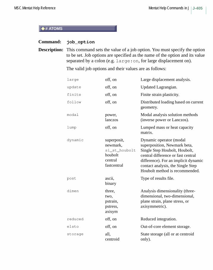
J-405MSC.Mentat Help Reference Mentat Help Commands in J
# ATOMS
Command: job_option
Description: This command sets the value of a job option. You must specify the option to be set. Job options are specified as the name of the option and its value separated by a colon (e.g. large:on, for large displacement on).
The valid job options and their values are as follows:
large off, on Large displacement analysis.
update off, on Updated Lagrangian.
finite off, on Finite strain plasticity.
follow off, on Distributed loading based on current geometry.
modal power,lanczos
Modal analysis solution methods (inverse power or Lanczos).
lump off, on Lumped mass or heat capacity matrix.
dynamic superposit,newmark,si_st_houbolthouboltcentralfastcentral
Dynamic operator (modal superposition, Newmark beta, Single Step Houbolt, Houbolt, central difference or fast central difference). For an implicit dynamic contact analysis, the Single Step Houbolt method is recommended.
post ascii,binary
Type of results file.
dimen three,two,pstrain,pstress,axisym
Analysis dimensionality (three- dimensional, two-dimensional, plane strain, plane stress, or axisymmetric).
reduced off, on Reduced integration.
elsto off, on Out-of-core element storage.
storage all,centroid
State storage (all or at centroid only).
# ATOMS

Mentat Help Commands in J MSC.Mentat Help ReferenceJ-406
solver dir_profile,it_ebe, it_sparse,nonsym,hardware,dir_sparse
Type of solver (direct profile, iterative element-by-element, iterative sparse matrix, nonsymmytric, hardware specific, or direct sparse matrix).
restart off, on,last
Write restart information (on, off, or last converged increment only).
access write,read,both
Type of restart file.
noprint off, on Suppress elemental and nodal output.
summary off, on Print increment summary.
version k5, k4 Marc version output file type.
elastic, off, on,nostore1,nostore2
Elastic analysis with multiple loads. The value nostore1 specifies that creep, swelling, plastic and incremental strains, plastic strain rates, and incremental strains should not be stored in the elastic analysis. The value nostore2 specifies that in addition to the above, strain energies, thermal strains, and elastic strains should not be stored. Do not specify nostore1 or nostore2 if a corresponding item is to be written to the post file.
distribution, linear,quadratic
Temperature distribution for shells.
interference, off, on Interference checking.
split, allowed,suppressed
Increment splitting.
style, double,single
Deformable-Deformable contact checking style.
sepinc, current,next
Separation increment.

J-407MSC.Mentat Help Reference Mentat Help Commands in J
chatter, allowed,suppressed
Contact chattering.
frictype, none,shear,coulomb,shear_roll,coulomb_roll
Contact friction type.
fricmeth, nstress,nforce
Friction method.
motion, off, on Call user subroutine MOTION.
sepfor, off, on Call user subroutine SEPFOR.
ufric, off, on Call user subroutine UFRIC.
uhtcoe, off, on Call user subroutine UHTCOE.
uhtcon, off, on Call user subroutine UHTCON.
ignore, off, on Ignore shell thickness.
cdamping, off, on Complex damping.
inertia, off, on Inertia effects.
creeptype, expl_maxw,viscopl,nassoc,impl_maxw
Creep type (explicit Maxwell, explicit viscoplastic, nonassociative flow rule, implicit Maxwell).
crpvis, off, on Call user subroutine CRPVIS.
rpflow, eulerupd_lagrange
Rigid-plastic procedure.
convective, off, on Convective terms.
tshear, off, on Transverse shear.
ebe_prec, none,inc_chol
Element-by-element solver precondition (none or incomplete Choleski).
sparse_prec, diag,scaled_diag,inc_chol
Sparse solver preconditioner (diagonal, scaled diagonal, or incomplete Choleski).
soil_calc, no_fluid,steady_state,transient
Soil calculations.
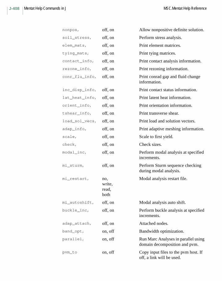
Mentat Help Commands in J MSC.Mentat Help ReferenceJ-408
nonpos, off, on Allow nonpositive definite solution.
soil_stress, off, on Perform stress analysis.
elem_mats, off, on Print element matrices.
tying_mats, off, on Print tying matrices.
contact_info, off, on Print contact analysis information.
rezone_info, off, on Print rezoning information.
conr_flu_info, off, on Print conrad gap and fluid change information.
inc_disp_info, off, on Print contact status information.
lat_heat_info, off, on Print latent heat information.
orient_info, off, on Print orientation information.
tshear_info, off, on Print transverse shear.
load_sol_vecs, off, on Print load and solution vectors.
adap_info, off, on Print adaptive meshing information.
scale, off, on Scale to first yield.
check, off, on Check sizes.
modal_inc, off, on Perform modal analysis at specified increments.
mi_sturm, off, on Perform Sturm sequence checking during modal analysis.
mi_restart, no,write,read,both
Modal analysis restart file.
mi_autoshift, off, on Modal analysis auto shift.
buckle_inc, off, on Perform buckle analysis at specified increments.
adap_attach, off, on Attached nodes.
band_opt, on, off Bandwidth optimization.
parallel, on, off Run Marc Analyses in parallel using domain decomposition and pvm.
pvm_to on, off Copy input files to the pvm host. If off, a link will be used.

J-409MSC.Mentat Help Reference Mentat Help Commands in J
Keyboard Command Sequence:
job_option <job option>:<value>
Other Buttons with the same description:
2-D3-DADVANCED OPTIONSALL BODIESALL POINTSANALYTICAL DESCRIPTION MODEL FATOM SIZEATTACHED NODESAUTO SHIFTAUTOMATICAXISYMMETRICCARTESIAN GRIDCENTRAL DIFFERENCECENTROIDCOMPLEX DAMPINGCONRAD GAP CONTACT FLUID CH.CONTACTCONVECTIVE TERMSCOPY TO CURRENTCUSTOMDEFAULTDIRECT PROFILEECHO OF CONNECTIVITYECHO OF COORDINATESECHO OF INPUT FILEELEC PROPS STRONG FUNC OF TEMPELEMENT MATRICESEQUIV. STRESS EULERIAN TOTAL EQUIV. PEULERIANEXPLICITFAST CENTRAL DIFFERENCEFULL ELEMENT GEOMETRIC DISTORTION NODE PRINTGEOMETRIC DISTORTIONIMMEDIATEIMPD (NODES)IMPLICITIMPLICITINCREM. DISP. (LOCAL)INERTIA EFFECTSINITIAL MESHINVERSE POWER SWEEP
pvm_back on, off Copy output files from the pvm host. If off, a link will be used.
pvm_debug off,level1,level2,level3
Level of pvm debug output.

Mentat Help Commands in J MSC.Mentat Help ReferenceJ-410
JOULE HEATINGLANCZOSLAST CONVERGED LAST CONVERGED ONLY PERIODICLAST CONVERGED ONLYLATENT HEATLINEARLOAD LOCAL ADAPTIVITY SOLUTION VECTORSLOCAL ADAPTIVITYMANUAL (.dat)MANUAL (.feb)MANUAL (.t18)MODAL INCREMENTSMODAL SUPERPOSITIONMODIFIEDMULTIFRONTAL SPARSEMULTIPLE INCREMENTS FILENEWMARKNO COPYNO FLUIDOFFONORIENTATIONPERFORM STRESS ANALYSISPLANARPLANE STRAINPLANE STRESSQUADRATICREADREAD REBARnVERIFICATION WRITEREBARnVERIFICATIONREZONINGSINGLE BODYSINGLE INCREMENT FILESINGLE INCREMENT FILE(S)SINGLE-STEP HOUBOLTSTEADY STATESTRESS DISCONTINUITYSTURM SEQUENCESUMMARYTHROUGH POINTTRANSIENTTRANSVERSE SHEARTYING MATRICESUNMODIFIEDUPDATED LAGRANGIANWRITE
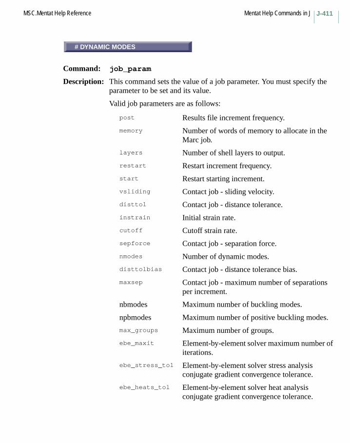
J-411MSC.Mentat Help Reference Mentat Help Commands in J
# DYNAMIC MODES
Command: job_param
Description: This command sets the value of a job parameter. You must specify the parameter to be set and its value.
Valid job parameters are as follows:
post Results file increment frequency.
memory Number of words of memory to allocate in the Marc job.
layers Number of shell layers to output.
restart Restart increment frequency.
start Restart starting increment.
vsliding Contact job - sliding velocity.
disttol Contact job - distance tolerance.
instrain Initial strain rate.
cutoff Cutoff strain rate.
sepforce Contact job - separation force.
nmodes Number of dynamic modes.
disttolbias Contact job - distance tolerance bias.
maxsep Contact job - maximum number of separations per increment.
nbmodes Maximum number of buckling modes.
npbmodes Maximum number of positive buckling modes.
max_groups Maximum number of groups.
ebe_maxit Element-by-element solver maximum number of iterations.
ebe_stress_tol Element-by-element solver stress analysis conjugate gradient convergence tolerance.
ebe_heats_tol Element-by-element solver heat analysis conjugate gradient convergence tolerance.
# DYNAMIC MODES

Mentat Help Commands in J MSC.Mentat Help ReferenceJ-412
condition Element-by-element solver condition number cutoff.
sparse_maxit Sparse solver maximum number of iterations.
sparse_tol Sparse solver convergence tolerance.
max_el Adaptive meshing maximum number of elements.
max_nod Adaptive meshing maximum number of nodes.
max_fixed_dof Adaptive meshing maximum fixed degrees-of-freedom.
max_cont_seg Adaptive meshing maximum contact segments.
max_cont_nod Adaptive meshing maximum contact nodes.
conversion Heat generation conversion factor.
mi_low Modal analysis Lanczos method lowest frequency.
mi_high Modal analysis Lanczos method highest frequency.
mi_nmodes Modal analysis Lanczos method number of modes.
mi_maxit Modal analysis power sweep method maximum number of iterations.
mi_tol Modal analysis power sweep method tolerance.
mi_initshift Modal analysis power sweep method initial shift.
mi_maxfreq Modal analysis power sweep method maximum frequency.
mi_shiftmodes Modal analysis power sweep method number of modes per shift.
mi_shiftpar Modal analysis power sweep method shift parameter.
bi_maxit Buckle analysis maximum number of iterations.
bi_tol Buckle analysis tolerance.
ncpus Number of cpus that Marc should utilize (on machines with multiple cpus only).
J-413MSC.Mentat Help Reference Mentat Help Commands in J
Keyboard Command Sequence:
job_param <job parameter name> <value>
Other Buttons with the same description:
# MODES# MODES PER SHIFT# RECYCLES# STEPS# USER DEFINED VECTORS (USER S% OF TOTAL LOAD2-D CONTACT LIMIT ANGLE3-D CONTACT LIMIT ANGLEBOUNDARY CONDITION PENALTY MULCONVERSION FACTORDYNAMIC CONTACT PROJECTION FACEND TIMEFLUID INCOMPRESSIBILITY PENALTFREQUENCYHIGHEST FREQUENCYINCREMENT FREQUENCYINCREMENTAL STRAIN PREDICTIONINITIAL SHIFTLOWEST FREQUENCYMAX # ITERATIONSMAX STEP SIZEMEAN STRESS SUBTRACTION FACTORNEWMARK-BETA BETA PARAMETERNEWMARK-BETA GAMMA PARAMETEROUT-OF-CORE THRESHOLDREASSEMBLY INTERVALRESTART INCREMENTRIGID PLASTIC CUTOFF STRAIN RARIGID PLASTIC INCOMPRESSIBILITRIGID PLASTIC INIT. STRAIN RATSHELL ELEMENT DRILLING MODE FASHIFT PARAMETERSINGLE-STEP HOUBOLT GAMMA PARASINGLE-STEP HOUBOLT GAMMA1 PARSTEFAN-BOLTZMANN CONSTANTTIME STEP (DYNAMIC ANALYSIS)TOLERANCEUNIVERSAL GAS CONSTANTXYZ

Mentat Help Commands in J MSC.Mentat Help ReferenceJ-414
BANDWIDTH OPTIMIZATION
Command: job_option band_opt
Description: This command activates the nodal bandwidth optimization for the current model.
This is important if a direct solver is used in order to minimize the solution time and the amount of storage.
For the iterative solvers, this parameter has no effect.
For the profile solver, the default method is the Sloan algorithm. If the Cuthill-McKee algorithm is to be used, the Marc input file must be modified.
For the sparse direct solver, the minimum degree algorithm is used.
Keyboard Command Sequence:
job_option band_opt:<on/off>
ALL POINTS
Command: job_option storage
Description: This command determines the way the calculation and storage of stresses and strains (or temperature for heat transfer) is handled.
ALL POINTS Stresses and strains (or temperatures) are calculated and stored in all integration points of the elements (default).
CENTROID Stresses and strains (or temperatures) are calculated and stored in the centroid of each element only. This can be used in a linear analysis in order to reduce storage requirements and computational cost. It should not be used in a nonlinear analysis.
Keyboard Command Sequence:
job_option storage:<all/centroid>
Another Button with the same description:
CENTROID
BANDWIDTH OPTIMIZATION
ALL POINTS

J-415MSC.Mentat Help Reference Mentat Help Commands in J
OUT-OF-CORE ELEMENT STORAGE
Command: job_option elsto
Description: This command flags the ELSTO option in Marc.
This has the effect that element quantities are stored out-of-core. This reduces the amount of main memory required in the analysis, but may increase the amount of I/O.
Reference: MSC.Marc Volume A: Theory and User Information, Chapter 2.
Keyboard Command Sequence:
job_option elsto:<on/off>
# SHELL/BEAM LAYERS
Command: job_param layers
Description: This command specifies the number of layers (through thickness integration points) that is used by shell and beam-in-a-plane elements.
This number must be odd.
For linear material behavior, one point is sufficient.
For most nonlinear problems, 7 points are sufficient to describe the response accurately. For extremely nonlinear response, such as elastic-plastic dynamic problems, 11 points might be needed.
Keyboard Command Sequence:
job_param layers <value>
OUT-OF-CORE ELEMENT STORAGE
# SHELL/BEAM LAYERS
Mentat Help Commands in J MSC.Mentat Help ReferenceJ-416
MEMORY ALLOCATION
Command: job_param memory
Description: This command is used for setting the amount of memory that MSC.Marc is to be use. MSC.Marc parameter sizing.
In the MSC.Marc release 7.1 and later, dynamic memory allocation is used. In this case, the value given here is the initial allocation. Additional memory is then requested when needed. If set to higher than what is needed, this amount is used in the analysis. If a zero value is given, a default value is used for the initial memory allocation (defined in the file include in the tools directory of the MSC.Marc distribution). In some cases, it is advisable to set a correct memory allocation, for instance, when amounts close to the limit of the computer is needed.
In earlier versions of MSC.Marc, the amount of memory needed in the analysis must be defined with this command.
Reference: MSC.Marc Volume: Program Input: Appendix B, page B-1
Keyboard Command Sequence: job_param memory <value>
OK
Menu: SOLVER
Description: This menu contains commands for choosing the solver type for the current job.
There are two types of solvers available in MSC.Marc: direct and iterative solvers.
The direct solvers use a strategy similar to classical Gaussian elimination but optimized for the special structure of the matrices in the finite element method.
The iterative solver is based on a preconditioned conjugate gradient method. The solution of the equation system is obtained in an iterative way. The number of iterations required for convergence is in general not known a priori. This type of solver can be very efficient in solving equation systems, both with respect to time and storage. These methods are not efficient if the equation system is ill-conditioned. This often occur in problems involving beams and shells due to the large difference in
MEMORY ALLOCATION
OK

J-417MSC.Mentat Help Reference Mentat Help Commands in J
membrane and bending stiffness. The performance of iterative solvers is often improved if preconditioners are used.
There is also the choice of storage method. The profile storage is advantageous if few zeros are present within the bandwidth. If the matrix is sparse, with many zeros within the bandwidth, the sparse storage system is more efficient.
For certain platforms (HP, SGI, and Sun), hardware optimized solvers are available. These are usually more efficient than the standard solvers. They can also be used in a parallel analysis.
The iterative solver is usually not appropriate for the following situations:
– elastic analysis with multiple load vectors– explicit creep analysis with multiple load vectors– complex harmonic analysis– substructures– beam and shell analysis– eigenvalue analysis– use of gap or Herrmann elements
Reference: MSC.Marc Volume A: Theory and User Information, Chapter 11
Another Button with the same description:SOLVER
CONDITON NR CUTOFF
Command: job_param condition
Description: This command is used for setting a condition number cut-off. If the calculated condition number of the equation system is less than this value, the analysis is stopped.
Note: This command is available in SuperForm only.
Keyboard Command Sequence:
job_param condition <value>
CONDITION NR CUTOFF
Mentat Help Commands in J MSC.Mentat Help ReferenceJ-418
HEAT ANALYSIS TOL.
Command: job_param ebe_heat_tol
Description: This command is used for setting the tolerance on conjugate gradient convergence for heat transfer analysis.
The solution is converged when the maximum residual force over the maximum reaction force is less than the specified tolerance.Note: This command is available in SuperForm only.
Keyboard Command Sequence: job_param ebe_heat_tol <value>
MAX # GROUPS
Command: job_param max_groups
Description: This command is used for setting the maximum number of groups used by the EBE iterative solver.
Note: This command is available in SuperForm only.
Keyboard Command Sequence: job_param max_groups <value>
MAX # ITERATIONS
Command: job_param ebe_maxit
Description: This command is used for setting the maximum number of conjugate gradient iterations.
Note: This command is available in SuperForm only.
Keyboard Command Sequence: job_param ebe_maxit <value>
HEAT ANALYSIS TOL.
MAX # GROUPS
MAX # ITERATIONS
J-419MSC.Mentat Help Reference Mentat Help Commands in J
NONE
Command: job_option ebe_prec
Description: This command is used for choosing a preconditioner for the EBE iterative solver.
A preconditioner is used for improving the convergence behavior of the iterative solver. Both sides of the equation is premultiplied with a preconditioning matrix.
NONE no preconditioner is used
INCOMPLETE CHOLESKI the use of this method usually improves convergence
Note: This command is available in SuperForm only.
Keyboard Command Sequence:job_option ebe_prec:<none/chol>
STRESS ANALYSIS TOL.
Command: job_param ebe_stress_tol
Description: This command is used for setting the tolerance on conjugate gradient convergence for stress analysis.
The solution is converged when the maximum residual force over the maximum reaction force is less than the specified tolerance.Note: This command is available in SuperForm only.
Keyboard Command Sequence: job_param ebe_stress_tol <value>
NONE
STRESS ANALYSIS TOL.

Mentat Help Commands in J MSC.Mentat Help ReferenceJ-420
OUT-OF-CORE THRESHOLD
Command: job_param hardw_sparse_thresh
Description: This command is used for setting a memory threshold for when the solver goes out-of-core.
This option is only available for the SGI hardware sparse solver. If the memory needed for the solver is larger than the specified limit, the solver will run out-of-core, that is, data needed for the solution is stored on the hard disk instead of being kept in memory. If zero is entered the limit is given by the maximum amount of memory allowed as defined by the variable MAXSIZE in the include file in the the tools subdirectory of the MSC.Marc installation directory.
Keyboard Command Sequence: job_param hardw_sparse_thresh <value>
DIRECT PROFILE
Command: job_option solver
Description: This command selects the solution method for linear equation systems. The following solvers are available:
DIRECT PROFILE
DIRECT SPARSE the default method.
ITERATIVE SPARSE uses a sparse storage method. Requires more input.
HARDWARE SPARSE available for HP, SGI, and Sun.
MULTIFRONTAL SPARSE a direct sparse solver
Solution of nonsymmetric systems can be performed with the MULTIFRONTAL SPARSE and the DIRECT PROFILE solver.
Out-of-core capabilities are available for all the solvers except the ITERATIVE SPARSE and HARDWARE SPARSE for HP and Sun. For a parallel run using domain decomposition, only MULTIFRONTAL SPARSE and HARDWARE SPARSE for SGI support of out-of-core solution.
OUT-OF-CORE THRESHOLD
DIRECT PROFILE

J-421MSC.Mentat Help Reference Mentat Help Commands in J
Systems with complex arithmetics is supported by MULTIFRONTAL SPARSE and DIRECT PROFILE, both for symmetric and nonsymmetric systems.
Reference: MSC.Marc Volume A: Theory and User Information, Chapter 11
Keyboard Command Sequence:
job_option solver:<dir_profile/dir_sparse/it_ebe/it_sparse/hardware/sparse/nonsym>
Other Buttons with the same description:
DIRECT SPARSEHARDWARE SPARSEITERATIVE SPARSEMULTIFRONTAL SPARSENONSYMMETRIC SOLUTION
MAX # ITERATIONS
Command: job_param sparse_maxit
Description: This command is used for setting the maximum number of conjugate gradient iterations. The job will stop if this maximum is reached.
Keyboard Command Sequence:
job_param sparse_maxit <value>
MAX # ITERATIONS
Mentat Help Commands in J MSC.Mentat Help ReferenceJ-422
DIAGONAL
Command: job_option sparse_prec
Description: This command is used for choosing a preconditioner for the sparse iterative solver.
A preconditioner is used for improving the convergence behavior of the iterative solver. Both sides of the equation is premultiplied with a preconditioning matrix.
DIAGONAL use the diagonal of the stiffness matrix.
SCALED DIAGONAL scale the diagonal terms appropriately in order to improve convergence.
INCOMPLETE CHOLESKI this is usually the method of choice.
Keyboard Command Sequence:
job_option sparse_prec:<diag/scaled_diag/inc_chol>
Other Buttons with the same description:
INCOMPLETE CHOLESKISCALED DIAGONAL
TOLERANCE
Command: job_param sparse_tol
Description: This command is used for setting the tolerance on conjugate gradient convergence for the sparse iterative solver.
The solution is converged when the maximum residual force over the maximum reaction force is less than the specified tolerance.
Keyboard Command Sequence:
job_param sparse_tol <value>
DIAGONAL
TOLERANCE

J-423MSC.Mentat Help Reference Mentat Help Commands in J
USER DATA MEMORY ALLOCATION
Command: job_param usdata_alloc
Description: This option invokes the call to MSC.Marc user subroutine USDATA for the initialization of user data.
In MSC.Marc, these data are stored in a common block USCADM that can be used in other subroutines. The value given in this option defines the amount of data used in this common block in real*4 words. This is needed for the memory allocation.
Keyboard Command Sequence: job_param usdata_alloc <value>
job_param_version
Command: job_option version
Description: This command toggles the release of MSC.Marc which is to be used in the current job.
Keyboard Command Sequence: job_option version:<k7/k6/k5/k4>
JOB PARAMETERS
Menu: PARAMETERS
Description: This popup menu contains commands for setting job parameters for the current job.
USER DATA MEMORY ALLOCATION
job_param_version
JOB PARAMETERS

Mentat Help Commands in J MSC.Mentat Help ReferenceJ-424
job_print_contact
Command: job_option contact_info
Description: This command turns on additional print of information about the contact to the output file.
Information is given on when a node comes into contact, what rigid body or segment is contacted, when separation occurs, when a node contacts a sharp corner, the displacements in the local system, and the force in the local coordinate system. For large problems, this can result in a significant amount of output.
Keyboard Command Sequence:
job_option contact_info:<on/off>
RESET
Command: job_reset
Description: This command resets all job parameters and options to their default values.
Keyboard Command Sequence: job_reset
RESTART FILE
Command: job_restart_file
Description: This command specifies the name of the job restart file.
Keyboard Command Sequence:
job_restart_file <file name>
job_print_contact
RESET
RESTART FILE

J-425MSC.Mentat Help Reference Mentat Help Commands in J
JOB RESULTS
Menu: JOB RESULTS
Description: This popup menu contains commands for selecting output parameters for the current job.
RUN
Menu: RUN
Description: This popup menu contains commands for controlling and running the current MSC.Marc job.
CHECK
Command: job_option check
Description: This command cause the MSC.Marc stop command to be written to the input file. When MSC.Marc is run, it will stop after memory allocation. Useful for finding out the amount of memory needed for the analysis.
Keyboard Command Sequence: job_option check:<on/off>
Another Button with the same description:CHECK SIZES
JOB RESULTS
RUN
CHECK
Mentat Help Commands in J MSC.Mentat Help ReferenceJ-426
COMPILE / NO SAVE
Command: job_option user_source
Description: This command defines how the user subroutine file defined for this job is to be treated.
COMPILE / NO SAVE The user subroutine file is compiled but the new executable file is not saved.
COMPILE AND SAVE The user subroutine file is compiled and the new executable file is saved. If the user subroutine file is called file.f, the executable will be called file.marc.
RUN SAVED EXECUTABLE Instead of compiling the user subroutine file, the previously saved executable is used.
Keyboard Command Sequence:
job_option user_source:<compile_nosave/compile_save/run_saved>
Another Button with the same description:
IMPORT
COMPILE / NO SAVE

J-427MSC.Mentat Help Reference Mentat Help Commands in J
DCOM
Command: job_option dcom:<on/off>
Description: This command toggles the DCOM server option in MSC.Marc.
It is only available for Windows.
If this option is on, the job_dcom_hostname command is enable to allow a server name to be specified in the adjacent job_dcom_hostname option.
To use this option, you MUST ensure that:
• The machine that is specified as the host must be enabled as a MSC.Marc DCOM server.
• Your datafiles are on shared directories.• Your username/password is the same as for the host.
Keyboard Command Sequence: job_option dcom:<on/off>
SETTINGS
Menu: SETTINGS
Description: This menu contains settings and definitions for the host file used in a network parallel job.
DCOM
SETTINGS
Mentat Help Commands in J MSC.Mentat Help ReferenceJ-428
NETWORK
Command: job_option parallel_setup
Description: This command sets the parallel execution type to SINGLE MACHINE or NETWORK. The number of processors to use in an analysis is equal to the number of domains created for the model.
SINGLE MACHINE The parallel analysis is performed on a single multiprocessor computer.
NETWORK The parallel analysis is performed on a network of separate computers. The machines to be used and other settings are defined under the SETTINGS menu.
Keyboard Command Sequence: job_option parallel_setup:<single/network>
Another Button with the same description:SINGLE MACHINE
USE DDM
Command: job_option parallel:<on/off>
Description: This command toggles the parallel option in MSC.Marc.
If this option is on, a parallel job is performed when one of the SUBMIT commands are used. Input files for a parallel job are written with the WRITE INPUT command.
The parallel option in MSC.Marc uses DDM (Domain Decomposition Method). The model is decomposed into domains of elements and each domain is solved on one processor (CPU). The communication of data between the CPUs is made using MPI (Message Passing Interface). The domains are created using the options under JOBS-> DOMAIN DECOMPOSITION.
The analysis can be performed on a single multiprocessor computer or on a network of separate computers.
Many of the features of MSC.Marc are supported in parallel mode. Specifically, the contact option including thermomechanical coupling is supported.
NETWORK
USE DDM
J-429MSC.Mentat Help Reference Mentat Help Commands in J
The list of unsupported features are:
Keyboard Command Sequence: job_option parallel:<on/off>
EXTENDED PRECISION INPUT FILE
Command: job_option inp_file_prec
Description: This command is used to set the option for using extended precision in the input file.
All integers are written using 10 digits instead of 5 with the normal option.
All floating point numbers are written using 20 or 30 positions instead of 10 or 15 with the normal option.
All character strings are written using 20 positions instead of 10 with the normal option.
This allows models with more than 99,999 elements which is the limit with the normal option.
Keyboard Command Sequence: job_option inp_file_prec:<normal/extended>
acoustics gap elements
adaptive harmonic
auto therm creep hydrodynamics
bearing j-integral
buckling out-of-core solver
beam-to-beam contact out-of-core element storage (elsto)
design sensitivity and optimization
radiation
electromagnetics response spectrum
explicit dynamics rezoning/remeshing
fluid and its coupled analysis
EXTENDED PRECISION INPUT FILE

Mentat Help Commands in J MSC.Mentat Help ReferenceJ-430
SELECTED USER SUBS
Menu: SEL. USER SUBS
Description: This menu contains a list of all user subroutines that are flagged to be used in the current model.
These subroutines are expected to be present in the user subroutine file selected by the USER SUB FILE button above (keyboard command job_usersub_file <file name>).
SCRATCH DIRECTORY
Command: job_scratch_dir
Description: This command allows you to set the directory that MSC.Marc will use to store scratch files. This defaults to directory in which the .dat file is located. This is used with the -sdir option to the run_marc command
Keyboard Command Sequence:job_scratch_dir <directory path>
SCRATCH DIRECTORY
Command: job_scratch directory
Description: This command allows you to set the directory that MSC.Marc will use to store scratch files. This defaults to directory in which the .dat file is located. This is used with the -sdir option to the run_marc command.
Keyboard Command Sequence:job_scratch_directory <directory path>
SELECTED USER SUBS
SCRATCH DIRECTORY
SCRATCH DIRECTORY
J-431MSC.Mentat Help Reference Mentat Help Commands in J
SORT CONSTRAINTS
Command: job_option des_sort_con:on(turns on the button)job_option des_sort_con:off(turns off the button)
Description: Pressing this button on specifies that the prescribed constraints will be sorted in order of criticalness before sensitivity analysis is performed. In this case, unless the # CRITICAL button is also pressed, the default number of constrained response quantities for which sensitivity analysis will be performed is set to the most critical 100 by default. If the # CRITICAL button is then pressed, the user can now change this default up or down.
STEADY STATE ROLLING
Menu: STEADY STATE ROLLING
Description: This popup menu contains commands for setting rotation and cornering axes parameters for steady state rolling.
X
Menu: STEADY STATE ROLLING PARAMETERS
Description: This menu contains commands for setting steady state rolling parameters.
AXIS OF ROTATIONThe axis of rotation is defined by specifying its DIRECTION and a POINT on the axis.
AXIS OF CORNERINGThe axis of cornering is defined by specifying its DIRECTION and a POINT on the axis.
Keyboard Command Sequence:job_param ss_roll_rot_axis_dir_x <x_component_of_direction>job_param ss_roll_rot_axis_dir_y <y_component_of_direction>job_param ss_roll_rot_axis_dir_z <z_component_of_direction>
job_param ss_roll_rot_axis_point_x <x_component_of_point>job_param ss_roll_rot_axis_point_y <y_component_of_point>job_param ss_roll_rot_axis_point_z <z_component_of_point>
SORT CONSTRAINTS
STEADY STATE ROLLING
X
Mentat Help Commands in J MSC.Mentat Help ReferenceJ-432
job_param ss_roll_corn_axis_dir_x <x_component_of_direction>job_param ss_roll_corn_axis_dir_y <y_component_of_direction>job_param ss_roll_corn_axis_dir_z <z_component_of_direction>
job_param ss_roll_corn_axis_point_x <x_component_of_point>job_param ss_roll_corn_axis_point_y <y_component_of_point>job_param ss_roll_corn_axis_point_z <z_component_of_point>
Other Buttons with the same description:YZ
RESET
Command: job_submit_reset
Description: This command resets the submit status of the current job to Not Submitted. This command is useful if a MSC.Marc job has been terminated before completion and MSC.Marc Mentat is not able to detect the fact that the job is no longer running.
Keyboard Command Sequence: job_submit_reset
OK
Command: job_title
Description: This command specifies an optional title to be written into the MSC.Marc input file.
Keyboard Command Sequence: job_title <job title>
Another Button with the same description:TITLE
RESET
OK

J-433MSC.Mentat Help Reference Mentat Help Commands in J
USER SUBROUTINE FILE
Command: job_usersub_file
Description: This command specifies the name of the file containing the source code for the user subroutines needed for the current job. The user is responsible for editing this file and providing the source code. Templates for most user subroutines can be found in the user subdirectory in the MSC.Marc directory.
The .f file name extension may be omitted.
Keyboard Command Sequence: job_usersub_file <file name>
CONTACT LOCATION MODEL FILES
Command: job_option write_contact_bm_bmjob_param bm_bm_files_freq
Description: The command "job_option write_contact_bm_bm" is used to make the location of the contact points in a beam-to-beam contact analysis available in formatted MSC.Marc Mentat model files, written by MSC.Marc.
The files contain line segments that connect the contact points on contacting beam elements. They can be merged with the current postprocessing model during postprocessing for visualization purposes. Since the location of these points may change from increment to increment, the contact location can be made available for different increments.
The frequency of writing this information is user-defined and can be set by the command "job_param bm_bm_files_freq". The files are named jobname_bbc_inc.mfd, in which inc is the increment number.
Also see: post_merge_bbc.
Keyboard Command Sequence: job_option write_contact_bm_bm_files:<on/off>job_param bm_bm_files_freq <value>
USER SUBROUTINE FILE
CONTACTCONTACT LOCATION MODEL FILES
Mentat Help Commands in J MSC.Mentat Help ReferenceJ-434
WRITE INPUT
Command: job_write_input
Description: This command writes the MSC.Marc input file without submitting the job. This command should be used when the input file needs to be inspected or modified before submission. The name of the file produced is determined from the current model and job names. After the input file has been created and/or modified, it may be submitted with the execute_job command.
Keyboard Command Sequence: job_write_input
ANALYTICAL DESCRIPTION MODEL FILES
Command: job_write_spline_files
Description: This option is used to get the spline description of analytical deformable contact bodies available in formatted MSC.Marc Mentat model files, written by MSC.Marc.
For a 2-D analysis, the spline description is represented by NURBS curves, for a 3-D analysis by NURBS surfaces. Moreover, the geometric entities representing the boundaries of contact bodies are stored in sets. Since the position and shape of a deformable contact body may change from increment to increment, the spline representation can be made available for different increments.
The frequency of writing this information is user-defined and can be set by the command "job_param spline_files_freq". The files are named jobname_spline_inc.mfd, in which inc is the increment number.
Keyboard Command Sequence: job_write_spline_files:<on/off>job_param spline_files_freq <value>
WRITE INPUT
WRITE INPUTCONTACT ANALYTICAL DESCRIPTION MODEL FILES
J-435MSC.Mentat Help Reference Mentat Help Commands in J
JOBS
Menu: JOBS
Description: The JOBS menu contains commands that define, run, and monitor MSC.Marc jobs.
JPEG QUALITY
Command: jpeg_quality
Description: This command will set the JPEG Quality factor. This value has a range of 1 through 100. The higher the value, the higher the color quality of the image, but it will result in a larger file size.
Keyboard Command Sequence:
jpeg_quality <value>
JPEG SMOOTHING
Command: jpeg_smoothing
Description: This command will set the JPEG Smoothness factor. This value has a range of 1 through 30. The higher the value, the more color blending and edge smoothing with adjacent pixels will take place, but you may see a loss of brightness. It only has a slight effect on file size.
Keyboard Command Sequence:
jpeg_smoothing <value>
JOBS
JPEG QUALITY
JPEG SMOOTHING

Mentat Help Commands in J MSC.Mentat Help ReferenceJ-436

Mentat Help Commands in KKILL
Command: kill_job
Description: This command terminates the currently running job.
The word STOP is written to the file jobname.cnt. Marc reads this file and exits with exit number 3020.
Keyboard Command Sequence:
kill_job
K Commands Begin with K
KILL

Mentat Help Commands in K MSC.Mentat Help ReferenceK-438

Mentat Help Commands in LLABEL CONTOURS
Command: label_contours
Description: This command sets whether or not contour line plots will be labeled.
Also see help: post_contour_lines
Keyboard Command Sequence:
label_contours <yes/no>
BOUNDARY CONDITION PENALTY MULTIPLIER
Command: loadcase_value bcond_pen_mp
Description: This command is used to enter the multiplier used to calculate the penalty factor to impose boundary conditions.
The penalty factor is this multiplier times the maxumum diagonal value of the operator matrix. The default multiplier is 1.0e9.
L Commands Begin with L
LABEL CONTOURS
BOUNDARY CONDITION PENALTY MULTIPLIER

Mentat Help Commands in L MSC.Mentat Help ReferenceL-440
This option is available in the LOADCASES->MECHANICAL->STATIC->
NUMERICAL PREFERENCES and other loadcase type menus.
Keyboard Command Sequence:
loadcase_value bcond_pen_mp <value>
NEWMARK-BETA BETA PARAMETER
Command: loadcase_value beta
Description: This command is used to enter the beta parameter used in transient dynamic analysis using the Newmark-Beta procedure. The default is 0.25.
This option is available in the LOADCASES->MECHANICAL->STATIC->
NUMERICAL PREFERENCES and other loadcase type menus.
Keyboard Command Sequence:
loadcase_value beta <value>
OFF
Command: loadcase_option approach_sync
Description: This command is used to specify the way rigid bodies are moved during a body approach loadcase. If the synchronize approach is turned off (default), then the rigid bodies are moved until they all touch a deformable body, whereas, if it is turned on the bodies are moved until one is touching a deformable body.
Keyboard Command Sequence:
loadcase_option approach_sync:<on/off>
Another Button with the same description:
ON
NEWMARK-BETA BETA PARAMETER
OFF
L-441MSC.Mentat Help Reference Mentat Help Commands in L
TOTAL LOADCASE TIME
Command: loadcase_value time
Description: This command is used to set the time period of the motion of the rigid bodies during the body approach loadcase.
This time period is only used for output purposes and to coordinate with tables and user subroutines. An exception is for coupled analysis where a transient period is performed.
Reference: MSC.Marc Volume C, Program Input, Chapter 4
Keyboard Command Sequence:
loadcase_value time <time period>
BODY APPROACH
Menu: BODY APPROACH
Description: This menu contains commands for defining the body approach as a loadcase. This allows you to move rigid bodies so that they make contact with deformable bodies. In the case of multistage forging, you usually have a time period where the first set of bodies are released, followed by a new time period where the second set of bodies are brought into contact.
This option is used in conjunction with the CONTACT TABLE option to determine which bodies are now applicable, and the MOTION CHANGE option which prescribes the velocity of the new bodies. A time step is associated with this period, but it is only used for output purposes and to coordinate with tables and user subroutines except in coupled analysis where a transient period is performed. Marc moves each rigid body until either all of the bodies are in contact or the first. This behavior depends on if the SYNCHRONIZE option is used or not.
Reference: MSC.Marc Volume C: Program Input, Chapter 4: History Definition APPROACHMSC.Marc Volume A: Theory and User Information, Chapter 8
TOTAL LOADCASE TIME
BODY APPROACH

Mentat Help Commands in L MSC.Mentat Help ReferenceL-442
BUCKLE
Menu: BUCKLE
Description: This menu contains commands for defining a buckling analysis as a loadcase.
By choosing this option, a buckling analysis will be performed in the current loadcase. A buckling analysis is usually performed after a preloading. The estimated buckling load is then given as a scaling of the preload. If the analysis is nonlinear prior to the buckle analysis, the formulation for large deformations should be used.
The only settings that are done in this menu are parameters for the inverse power sweep method. All other settings are done in the JOBS menus. The choice between the inverse power sweep method and the Lanczos method is done under JOBS->MECHANICAL->ANALYSIS OPTIONS and the specification of the number of buckling modes to be extracted is done under JOBS->MECHANICAL->JOB PARAMETERS. The eigenvectors, stresses and the reactions are automatically set to be printed out to the post file.
The option in Marc to perform a perturbation of the geometry by the buckling mode is not yet supported by Mentat and must be entered into the input file by the user.
A related command is the BUCKLE INCREMENT entered under JOBS->MECHANICAL->ANALYSIS OPTIONS which allows a buckling analysis to be performed after given increments in a loadcase. This can be used instead of the current option or in connection with it.
Reference: MSC.Marc Volume C: Program Input, Chapter 2 and Chapter 4MSC.Marc Volume A: Theory and User Information, Chapter 5
MAX # ITERATIONS
Command: loadcase_value buckle_tolloadcase_value maxit
Description: These commands specify parameters for the inverse power sweep method if it is used in the current loadcase.
BUCKLE
MAX # ITERATIONS
L-443MSC.Mentat Help Reference Mentat Help Commands in L
The power sweep terminates when the difference between the eigenvalues in two consecutive sweeps divided by the eigenvalue is less than the tolerance.
If the number of iteration required is larger than the maximum specified, the analysis stops. The default number is 40.
Reference: MSC.Marc Volume C, Program Input, Chapter 4
Keyboard Command Sequence: loadcase_value buckle_tol
<tolerance for the inverse power sweep method>loadcase_value maxit
<maximum number of iterations>
Another Button with the same description:TOLERANCE
CONVERGENCE TESTING
Menu: CONVERGENCE TESTING
Description: This popup menu contains commands for setting convergence testing parameters for the current loadcase.
Other Buttons with the same description:CONVERGENCE TESTING FLUID REGICONVERGENCE TESTING HEAT TRANSCONVERGENCE TESTING SOLID REGI
TOTAL CREEP TIME
Command: loadcase_value creeptime
Description: This command is used to enter the total creep time to be covered during this AUTO THERM CREEP option. This value can be changed at restart by using the RESTART option. The default is 0.
This option is available in the LOADCASES->MECHANICAL->CREEP->
(TEMPERATURE, CREEP STRAIN/STRESS)->PARAMETERS menu.
Keyboard Command Sequence: loadcase_value creeptime <value>
CONVERGENCE TESTING
TOTAL CREEP TIME
Mentat Help Commands in L MSC.Mentat Help ReferenceL-444
FIT
Command: loadcase_value cutoff_stress
Description: This command is used to enter the tolerance on low stress point cut-off.
Points with a stress lower than this ratio relative to the maximum stress in the structure are not used in the creep tolerance checking. The default is 0.05.
This option is available in the LOADCASES->MECHANICAL->CREEP->(CREEP
STRAIN/STRESS)->PARAMETERS menu.
Keyboard Command Sequence: loadcase_value cutoff_stress <value>
DESIGN CONSTRAINTS
Menu: DESIGN CONSTRAINTS
Description: Pressing this button will bring up the pop-up menu for associating previously specified design constraints (see the button DESIGN in the Main Menu) with the current loadcase being defined.
MAX PRESSURE CHANGE ALLOWED
Command: loadcase_value dp_allowed
Description: This command specifies the maximum nodal pressure change allowed. It is used to control the automatic time step scheme for heat transfer.
This option is available in the LOADCASES->THERMAL-DIFFUSION-> TRANSIENT->CONVERGENCE TESTING menu.
Keyboard Command Sequence:
loadcase_value dp_allowed <value>
CUTOFF STRESS TOLERANCE
DESIGN CONSTRAINTS
MAX PRESSURE CHANGE ALLOWED
L-445MSC.Mentat Help Reference Mentat Help Commands in L
MAX PRESSURE CHANGE BEFORE REASSEMBLY
Command: loadcase_value dp_assemble
Description: This command specifies the maximum nodal pressure change allowed before properties are re-evaluated and matrices reassembled.
The default value is 100 degrees.
This option is available in the LOADCASES->THERMAL-DIFFUSION-> TRANSIENT->CONVERGENCE TESTING menu.
Keyboard Command Sequence:
loadcase_value dp_assemble <value>
MAX ERROR IN PRESSURE ESTIMATE
Command: loadcase_value dp_error
Description: This command specifies the maximum error in pressure estimate used for property evaluation. This control provides a recycling capability to improve accuracy in highly nonlinear heat transfer problems (for example, latent heat, radiation boundary conditions).
The default value is 0, which bypasses this test. It should be set to the maximum pressure error which is considered acceptable.
This option is available in the LOADCASES->THERMAL-DIFFUSION-> STEADY STATE->CONVERGENCE TESTING and TRANSIENT menus.
Keyboard Command Sequence:
loadcase_value dp_error <value>
MAX PRESSURE CHANGE BEFORE REASSEMBLY
MAX ERROR IN PRESSURE ESTIMATE
Mentat Help Commands in L MSC.Mentat Help ReferenceL-446
MAX TEMPERATURE CHANGE ALLOWED
Command: loadcase_value dt_allowed
Description: This command specifies the maximum nodal temperature change allowed. It is used to control the automatic time step scheme for heat transfer.
This option is available in the LOADCASES->HEAT TRANSFER->TRANSIENT->
CONVERGENCE TESTING menu.
Keyboard Command Sequence: loadcase_value dt_allowed <value>
MAX TEMPERATURE CHANGE BEFORE REASSEMBLY
Command: loadcase_value dt_assemble
Description: This command specifies the maximum nodal temperature change allowed before properties are re-evaluated and matrices reassembled.The default value is 100 degrees.
This option is available in the LOADCASES->HEAT TRANSFER->TRANSIENT->
CONVERGENCE TESTING menu.
Keyboard Command Sequence: loadcase_value dt_assemble <value>
MAX ERROR IN TEMPERATURE ESTIMATE
Command: loadcase_value dt_error
Description: This command specifies the maximum error in temperature estimate used for property evaluation. This control provides a recycling capability to improve accuracy in highly nonlinear heat transfer problems (for example, latent heat, radiation boundary conditions).
The default value is 0, which bypasses this test. It should be set to the maximum temperature error which is considered acceptable.
This option is available in the LOADCASES->HEAT TRANSFER->STEADY
STATE->CONVERGENCE TESTING and TRANSIENT menus.
Keyboard Command Sequence: loadcase_value dt_error <value>
MAX TEMPERATURE CHANGE ALLOWED
MAX TEMPERATURE CHANGE BEFORE REASSEMBLY
MAX ERROR IN TEMPERATURE ESTIMATE
L-447MSC.Mentat Help Reference Mentat Help Commands in L
DYNAMIC CONTACT PROJECTION FACTOR
Command: loadcase_value dyn_contact_pro
Description: This command is used to enter the surface projection factor for the Single Step Houbolt procedure. The default is 0.0.
This option is available in the LOADCASES->MECHANICAL->STATIC-> NUMERICAL PREFERENCES and other loadcase type menus.
Keyboard Command Sequence: loadcase_value dyn_contact_pro <value>
FLUID INCOMPRESSIBILITY PENALTY
Command: loadcase_value fluid_incomp_pen
Description: This command is used to enter the penalty factor used to satisfy incompressibility in fluid analysis when displacement elements are used. The default is 1.0e6.
This option is available in the LOADCASES->MECHANICAL->STATIC-> NUMERICAL PREFERENCES and other loadcase type menus.
Keyboard Command Sequence: loadcase_value fluid_incomp_pen <value>
MAXIMUM ABSOLUTE VELOCITY
Command: loadcase_value fluid_maxvelo
Description: This command specifies the convergence tolerance when absolute residual testing on velocity is used. If set to zero, no checking on residual velocity takes place.
This option is available in the LOADCASES->FLUID->STEADY STATE->
CONVERGENCE TESTING and other FLUID loadcase class menus.
Reference: Volume A: Theory and User Information, Chapter 11.
Keyboard Command Sequence: loadcase_value fluid_maxvelo <value>
DYNAMIC CONTACT PROJECTION FACTOR
FLUID INCOMPRESSIBILITY PENALTY
MAXIMUM ABSOLUTE VELOCITY

Mentat Help Commands in L MSC.Mentat Help ReferenceL-448
MINIMUM VELOCITY CUTOFF
Command: loadcase_value fluid_minvelo
Description: This command specifies a cutoff value for the velocity if relative testing on velocity is used. If the velocity is less than this value, checking will be bypassed, or if the RELATIVE/ABSOLUTE option is used, absolute testing will be used.
This option is available in the LOADCASES->FLUID->STEADY STATE->
CONVERGENCE TESTING and other FLUID loadcase class menus.
Reference: Volume A: Theory and User Information, Chapter 11.
Keyboard Command Sequence: loadcase_value fluid_minvelo <value>
RELATIVE VELOCITY TOLERANCE
Command: loadcase_value fluid_velo
Description: This command specifies the convergence tolerance when relative residual testing on velocity is used.
This option is available in the LOADCASES->FLUID->STEADY STATE->
CONVERGENCE TESTING and other FLUID loadcase class menus.
Reference: Volume A: Theory and User Information, Chapter 11.
Keyboard Command Sequence: loadcase_value fluid_velo <value>
NEWMARK-BETA GAMMA PARAMETER
Command: loadcase_value gamma
Description: This command is used to enter the gamma parameter used in transient dynamic analysis using the Newmark-Beta procedure. The default is 0.50.
This option is available in the LOADCASES->MECHANICAL->STATIC-> NUMERICAL PREFERENCES and other loadcase type menus.
Keyboard Command Sequence: loadcase_value gamma <value>
MINIMUM VELOCITY CUTOFF
RELATIVE VELOCITY TOLERANCE
NEWMARK-BETA GAMMA PARAMETER
L-449MSC.Mentat Help Reference Mentat Help Commands in L
HIGHEST FREQUENCY
Command: loadcase_value high
Description: This command is used to enter the highest frequency of mode to be extracted in cycles per time if the job option LANCZOS is selected.
For a DYNAMIC MODAL analysis, this value is used provided that the option RANGE (loadcase_option frequency:range) is selected. When the option RANGE is not used, the value set with the # MODES button (loadcase_value nmodes) is used.This can be changed upon restart.
This option is available in the LOADCASES->MECHANICAL->DYNAMIC MODAL,
DYNAMIC HARMONIC and SPECTRUM RESPONSE menus.
Also see the help for the loadcase_option frequency (the NUMBER or RANGE buttons).
Keyboard Command Sequence: loadcase_value high <value>
INACTIVE ELEMENTS
Command: loadcase_option inactive_elements
Menu: LOADCASES
Description: This option is used to specify the type of input of inactive elements.If manual is selected, the user can manually select inactive elements using Add/Remove.If import is selected, user can specify the name of the file that contains the cutter path information.
Two types of the cutter path data are supported here:
APT source: Cutter path data output by CATIA. This file must have extension .apt.
CL file: Cutter path data output by APT compilers. This file must have extension .ccl.
Notes: 1. The cutter path file must reside in the job directory.2. If no extension for the file name is given, MSC.Marc program will add the
extensions: .apt or .ccl, automatically.
Keyboard Command Sequence: loadcase_option inactive_elements:<manual/import>
HIGHEST FREQUENCY
INACTIVE ELEMENTS
Mentat Help Commands in L MSC.Mentat Help ReferenceL-450
# INCS BETWEEN REASSEMBLY
Command: loadcase_value inc_assemble
Description: This command is used to enter the number of increments between stiffness matrix updates. This option is used to prevent unnecessary updating of the stiffness matrix during large displacement analysis.
This option is available in the LOADCASES->MECHANICAL->CREEP->(CREEP
STRAIN/STRESS)->PARAMETERS and other ADAPTIVE STEPPING menus.
Keyboard Command Sequence: loadcase_value inc_assemble <value>
INCREMENTAL STRAIN PREDICTION MULTIPLIER
Command: loadcase_value inc_strn_pred_mp
Description: This command is used to enter the incremental strain prediction multiplier. The default is 1.0.
This option is available in the LOADCASES->MECHANICAL->STATIC->
NUMERICAL PREFERENCES and other loadcase type menus.
Keyboard Command Sequence: loadcase_value inc_strn_pred_mp <value>
INITIAL SHIFT
Command: loadcase_value initshift
Description: This command is used to enter the initial shift in cycles per time. The power shift is likely to start converging to the eigenvalue closest to this value. The default is 0.
This option is available in the LOADCASES->MECHANICAL->DYNAMIC MODAL menu.
Keyboard Command Sequence: loadcase_value initshift <value>
# INCS BETWEEN REASSEMBLY
INCREMENTAL STRAIN PREDICTION MULTIPLIER
INITIAL SHIFT

L-451MSC.Mentat Help Reference Mentat Help Commands in L
INITIAL TIME INITIAL TIME STEP
Command: loadcase_value inittime
Description: This command is used to enter the suggested time increment for the analysis.
When the automatic creep control is in use, MSC.Marc iterates for the appropriate increment size to satisfy the tolerances placed on stress and strain increments. The default is 1.0.
This option is available in the LOADCASES->MECHANICAL->CREEP->(CREEP
STRAIN/STRESS)->PARAMETERS menu.
Keyboard Command Sequence: loadcase_value inittime <value>
2-D CONTACT LIMIT ANGLE
Command: loadcase_value limit_angle_2d
Description: This command is used to enter the angle at which a node separates from a convex corner or becomes stuck in a concave corner for two-dimensional contact. The default is 8.625 degrees.
This option is available in the LOADCASES->MECHANICAL->STATIC->
NUMERICAL PREFERENCES and other loadcase type menus.
Keyboard Command Sequence: loadcase_value limit_angle_2d <value>
3-D CONTACT LIMIT ANGLE
Command: loadcase_value limit_angle_3d
Description: This command is used to enter the angle at which a node separates from a convex corner or becomes stuck in a concave corner for three-dimensional contact. The default is 20.0 degrees.
This option is available in the LOADCASES->MECHANICAL->STATIC->
NUMERICAL PREFERENCES and other loadcase type menus.
Keyboard Command Sequence: loadcase_value limit_angle_3d <value>
INITIAL TIME STEP
2-D CONTACT LIMIT ANGLE
3-D CONTACT LIMIT ANGLE
Mentat Help Commands in L MSC.Mentat Help ReferenceL-452
LOADS
Menu: LOADS
Description: This popup menu contains commands for selecting loads and boundary condition applications for the current loadcase.
LOWEST FREQUENCY
Command: loadcase_value low
Description: This command is used to enter the lowest frequency of mode to be extracted in cycles per time. This is also the initial shift point. This cannot be changed upon restart. The default is 0.
This option is available in the LOADCASES->MECHANICAL->DYNAMIC MODAL, DYNAMIC HARMONIC, and SPECTRUM RESPONSE menus.
Keyboard Command Sequence: loadcase_value low <value>
MAXIMUM ITERATIVE DISPLACEMENT COMPONENT
Command: loadcase_value max_it_disp_comp
Description: This command is used to enter the maximum iterative displacement component. The default is 1.0e30.
This option is available in the LOADCASES->MECHANICAL->STATIC->
NUMERICAL PREFERENCES and other loadcase type menus.
Keyboard Command Sequence:
loadcase_value max_it_disp_comp <value>
LOADS
LOWEST FREQUENCY
MAXIMUM ITERATIVE DISPLACEMENT COMPONENT

L-453MSC.Mentat Help Reference Mentat Help Commands in L
MAXIMUM # INCREMENTS
Command: loadcase_value maxinc
Description: This command is used to enter the maximum number of time increments to be allowed during this part of the analysis. The default is 50 increments.
This option is available in the LOADCASES->MECHANICAL->STATIC->(ARC
LENGTH)->PARAMETERS and other loadcase type menus.
Keyboard Command Sequence: loadcase_value maxinc <value>
MAXIMUM # INTERATIONS
Command: loadcase_value maxit
Description: This command is used to enter the value for the maximum number of iterations allowed to modify the time step during an increment. The default is 5.
This option is available in the LOADCASES->MECHANICAL->BUCKLE and LOADCASES->MECHANICAL->STATIC->(CREEP STRAIN/STRESS)->
PARAMETERS menus.
Keyboard Command Sequence: loadcase_value maxit <value>
MAX # SUBINCREMENTS
Command: loadcase_value maxsubinc
Description: This command is used to enter the maximum number of subincrements to be allowed during this part of the creep analysis. The default is 50.
This option is available in the LOADCASES->MECHANICAL->CREEP->
(TEMPERATURE CREEP STRAIN/STRESS)->PARAMETERS menu.
Keyboard Command Sequence: loadcase_value maxsubinc <value>
MAXIMUM # INCREMENTS
MAXIMUM # INTERATIONS
MAX # SUBINCREMENTS

Mentat Help Commands in L MSC.Mentat Help ReferenceL-454
MEAN STRESS SUBTRACTION FACTOR
Command: loadcase_value mean_strs_subtr
Description: This command is used to enter the fraction of the hydrostatic pressure that is subtracted from the stress tensor in the initial stress calculation. The default is 1.0.
This option is available in the LOADCASES->MECHANICAL->STATIC->
NUMERICAL PREFERENCES and other loadcase type menus.
Keyboard Command Sequence: loadcase_value mean_strs_subtr <value>
# FREQUENCIES
Command: loadcase_value nfreq
Description: This command is used to enter the maximum number of frequencies to be extracted in a dynamic harmonic analysis. The default is 1.
This option is available in the LOADCASES->MECHANICAL->DYNAMIC
HARMONIC menu.
Keyboard Command Sequence: loadcase_value nfreq <value>
# MODES
Command: loadcase_value nmodes
Description: This command is used to enter the number of modes to be extracted in cycles per time provided that the option NUMBER (loadcase_option frequency:number) is used.
When the option NUMBER is not used, the value set with the HIGHEST
FREQUENCY button (loadcase_value high) is used. This can be changed upon restart. The default is 10.
This option is available in the LOADCASES->MECHANICAL->DYNAMIC MODAL, DYNAMIC HARMONIC, and SPECTRUM RESPONSE menus.
Also see the help for the loadcase_option frequency (the NUMBER or RANGE buttons).
MEAN STRESS SUBTRACTION FACTOR
# FREQUENCIES
# MODES
L-455MSC.Mentat Help Reference Mentat Help Commands in L
Keyboard Command Sequence: loadcase_value nmodes <value>
lcase_piezo_el_buckle
Menu: BUCKLE
Description: This menu contains commands for defining a buckling analysis as a loadcase.
By choosing this option, a buckling analysis will be performed in the current loadcase. A buckling analysis is usually performed after a pre-loading. The estimated buckling load is then given as a scaling of the preload. If the analysis is nonlinear prior to the buckle analysis, the formulation for large deformations should be used.
The only settings that are done in this menu are parameters for the inverse power sweep method. All other settings are done in the JOBS menus. The choice between the inverse power sweep method and the Lanczos method is done under
JOBS->PIEZO-ELECTRIC->ANALYSIS OPTIONS
and the specification of the number of buckling modes to be extracted is done under
JOBS->PIEZO-ELECTRIC->JOB PARAMETERS.
The eigenvectors, stresses and the reactions are automatically set to be printed out to the post file.
The option in MSC.Marc to perform a perturbation of the geometry by the buckling mode is not yet supported by MSC.Marc Mentat and must be entered into the input file by the user.
A related command is the BUCKLE INCREMENT entered under JOBS->
PIEZO-ELECTRIC->ANALYSIS OPTIONS which allows a buckling analysis to be performed after given increments in a loadcase. This can be used instead of the current option or in connection with it.
MECHANICAL and ELECTROSTATIC boundary conditions can be selected.
Make sure that for piezo electric elements the MECHANICAL,
ELECTROSTATIC and PIEZO-ELECTRIC material properties are set.
Reference: MSC.Marc Volume A: Theory and User Information, Chapter 5MSC.Marc Volume C: Program Input, Chapter 2 & 4
BUCKLE
Mentat Help Commands in L MSC.Mentat Help ReferenceL-456
CREEP
Menu: CREEP
Description: This button sets the current loadcase to be a piezo-electric creep analysis.
The menu contains commands for defining active loads, solution controls, convergence testing parameters, active contact definitions, numerical parameter settings, and details of the load stepping procedure.
MECHANICAL and ELECTROSTATIC boundary conditions can be selected.
Make sure that for piezo electric elements the MECHANICAL, ELECTROSTATIC, and PIEZO-ELECTRIC material properties are set.
DYNAMIC HARMONIC
Menu: DYNAMIC HARMONIC
Description: This button sets the current loadcase to be a piezo-electric dynamic harmonic analysis.
The menu contains commands to set the harmonic loads and the number of frequencies with the range.
MECHANICAL and ELECTROSTATIC boundary conditions can be selected.
Make sure that for piezo electric elements, the MECHANICAL,
ELECTROSTATIC and PIEZO-ELECTRIC material properties are set.
DYNAMIC MODAL
Menu: DYNAMIC MODAL
Description: This button sets the current loadcase to be a piezo-electric dynamic modal analysis.
The menu contains commands for the lanczos method and for the power sweep method.
MECHANICAL and ELECTROSTATIC boundary conditions will be used if they are set as initial boundary conditions in JOBS.
Make sure that for piezo electric elements the MECHANICAL, ELECTROSTATIC, and PIEZO-ELECTRIC material properties are set.
CREEP
DYNAMIC HARMONIC
DYNAMIC MODAL
L-457MSC.Mentat Help Reference Mentat Help Commands in L
DYNAMIC TRANSIENT
Menu: DYNAMIC TRANSIENT
Description: This button sets the current loadcase to be a piezo-electric dynamic transient analysis.
The menu contains commands for defining active loads, solution controls, convergence testing parameters, active contact definitions, numerical parameter settings, and details of the load stepping procedure.
MECHANICAL and ELECTROSTATIC boundary conditions can be selected.
Make sure that for piezo electric elements the MECHANICAL, ELECTROSTATIC and PIEZO-ELECTRIC material properties are set.
STATIC
Menu: STATIC
Description: This button sets the current loadcase to be a piezo-electric static analysis.
The menu contains commands for defining active loads, solution controls, convergence testing parameters, active contact definitions, numerical parameter settings, and details of the load stepping procedure.
MECHANICAL and ELECTROSTATIC boundary conditions can be selected.
Make sure that for piezo electric elements the MECHANICAL, ELECTROSTATIC and PIEZO-ELECTRIC material properties are set.
DYNAMIC TRANSIENT
STATIC
Mentat Help Commands in L MSC.Mentat Help ReferenceL-458
HIGHEST FREQUENCY
Command: loadcase_value pshigh
Description: This command is used to enter the maximum frequency to be extracted in cycles per time if the job option INVERSE POWER SWEEP is selected. If this value is zero, the number of modes requested on the DYNAMIC parameter is extracted. If this value is nonzero, the extraction ends when this frequency is exceeded or when the number of modes requested on the DYNAMIC parameter is reached, whichever occurs first. The default is 0.
This option is available in the LOADCASES->MECHANICAL->DYNAMIC
MODAL menu.
Keyboard Command Sequence: loadcase_value pshigh <value>
RIGID PLASTIC CUTOFF STRAIN RATE
Command: loadcase_value rp_ctff_strn_rt
Description: This command is used to enter the cutoff strain rate for rigid plastic analysis. The default is 1.0e-12.
This option is available in the LOADCASES->MECHANICAL->STATIC->
NUMERICAL PREFERENCES and other loadcase type menus.
Keyboard Command Sequence: loadcase_value rp_ctff_strn_rt <value>
HIGHEST FREQUENCY
RIGID PLASTIC CUTOFF STRAIN RATE
L-459MSC.Mentat Help Reference Mentat Help Commands in L
RIGID PLASTIC INCOMPRESSIBILITY PENALTY
Command: loadcase_value rp_incomp_pen
Description: This command is used to enter the penalty factor used to satisfy the incompressibility in rigid plastic analysis for plane strain, axisymmetric, or solid analysis when displacement elements are used. The default is 100.
This option is available in the LOADCASES->MECHANICAL->STATIC->
NUMERICAL PREFERENCES and other loadcase type menus.
Keyboard Command Sequence: loadcase_value rp_incomp_pen <value>
RIGID PLASTIC INIT. STRAIN RATE
Command: loadcase_value rp_init_strn_rt
Description: This command is used to enter the initial strain ratefor rigid plastic analysis. The default is 1.0e-4.
This option is available in the LOADCASES->MECHANICAL->STATIC->
NUMERICAL PREFERENCES and other loadcase type menus.
Keyboard Command Sequence: loadcase_value rp_init_strn_rt <value>
SHELL ELEMENT DRILLING MODE FACTOR
Command: loadcase_value shell_drill
Description: This command is used to enter the factor used to calculate the drilling mode for shell elements type 22, 75, 138, 139, and 140. The default is 0.0001.
This option is available in the LOADCASES->MECHANICAL->STATIC->
NUMERICAL PREFERENCES and other loadcase type menus.
Keyboard Command Sequence: loadcase_value shell_drill <value>
RIGID PLASTIC INCOMPRESSIBILITY PENALTY
RIGID PLASTIC INIT. STRAIN RATE
SHELL ELEMENT DRILLING MODE FACTOR

Mentat Help Commands in L MSC.Mentat Help ReferenceL-460
# MODES PER SHIFT
Command: loadcase_value shiftmodes
Description: This command is used to enter the number of modes extracted per shift. This data field is active only if AUTO SHIFT is selected. If AUTO SHIFT is not required, it is set equal to or greater than the number of modes requested on the DYNAMIC parameter. The default is 5.
This option is available in the LOADCASES->MECHANICAL->DYNAMIC
MODAL menu.
Also see the help for the loadcase_option autoshift (AUTO SHIFT).
Keyboard Command Sequence: loadcase_value shiftmodes <value>
SHIFT PARAMETER
Command: loadcase_value shiftpar
Description: This command is used to enter the AUTO SHIFT parameter. MSC.Marc determines the new shift point (in frequency squared) as the highest frequency square plus this times the difference between the highest and the next highest distinct frequency squared. The default is 1.0.
This option is available in the LOADCASES->MECHANICAL->DYNAMIC
MODAL menu.
Also see the help for the loadcase_option autoshift (AUTO SHIFT).
Keyboard Command Sequence: loadcase_value shiftpar <value>
SINGLE-STEP HOUBOLT GAMMA PARAMETER
Command: loadcase_value si_st_hou_gamma
Description: This command is used to enter the gamma parameter used in transient dynamic analysis using the Single Step Houbolt procedure. The default is -.50.
This option is available in the LOADCASES->MECHANICAL->STATIC->
NUMERICAL PREFERENCES and other loadcase type menus.
# MODES PER SHIFT
SHIFT PARAMETER
SINGLE-STEP HOUBOLT GAMMA PARAMETER

L-461MSC.Mentat Help Reference Mentat Help Commands in L
Keyboard Command Sequence: loadcase_value si_st_hou_gamma <value>
SINGLE-STEP HOUBOLT GAMMA1 PARAMETER
Command: loadcase_value si_st_hou_gamma1
Description: This command is used to enter the gamma1 parameter used in transient dynamic analysis using the Single Step Houbolt procedure. The default is 1.50.
This option is available in the LOADCASES->MECHANICAL->STATIC->
NUMERICAL PREFERENCES and other loadcase type menus.
Keyboard Command Sequence: loadcase_value si_st_hou_gamma1 <value>
SOLUTION CONTROL
Menu: SOLUTION CONTROL
Description: This popup menu contains commands for setting solution control parameters for the current loadcase.
STEADY STATE ROLLING
Menu: STEADY STATE ROLLING
Description: This popup menu contains commands for setting steady state rolling parameters for the current loadcase.
STEADY STATE ROLLING
Menu: STEADY STATE ROLLING
Description: This button sets the current loadcase to be a steady state rolling analysis.
The menu contains commands for defining active loads, solution controls, convergence testing parameters, active contact definitions, steady state rolling parameters, numerical parameter settings and details of the load stepping procedure.
SINGLE-STEP HOUBOLT GAMMA1 PARAMETER
SOLUTION CONTROL
STEADY STATE ROLLING
STEADY STATE ROLLING
Mentat Help Commands in L MSC.Mentat Help ReferenceL-462
VAR ID
Command: loadcase_value state_var_id
Description: This command specifies the state variable identifier to be used in the analysis.
This option is available in the LOADCASES->HEAT TRANSFER-> TRANSIENT->(MULTICRITERIA)->PARAMETERS->USER-DEFINED CRITERIA, and also under the JOULE HEATING and JOULE-MECHANICAL loadcase class menus.
Keyboard Command Sequence: loadcase_value state_var_id <value>
STATIC
Menu: STATIC
Description: This button sets the current loadcase to be a mechanical static analysis.
The menu contains commands for defining active loads, solution controls, convergence testing parameters, active contact definitions, active gap geometries, numerical parameter settings, active design constraints, and details of the load stepping procedure.
STRAIN CHANGE TOLERANCE
Command: loadcase_value strain_change
Description: This command is used to enter the appropriate creep strain value.
If RELATIVE testing is selected, enter the tolerance on the creep strain increment relative to the elastic strain. The default is 0.50. Note that a high value is likely to cause stability problems.
If ABSOLUTE testing is selected, enter the maximum creep strain increment allowed. The default is 0.1.
This option is available in the LOADCASES->MECHANICAL->CREEP->(CREEP
STRAIN/STRESS)->PARAMETERS menu.
Keyboard Command Sequence: loadcase_value strain_change <value>
VAR ID
STATIC
STRAIN CHANGE TOLERANCE

L-463MSC.Mentat Help Reference Mentat Help Commands in L
STRESS CHANGE TOLERANCE
Command: loadcase_value stress_change
Description: This command is used to enter the appropriate creep stress value.
If RELATIVE testing is selected, enter the tolerance on the stress change per stress during creep. The default is 0.10.
If ABSOLUTE testing is selected, enter the maximum stress increment allowed. The default is 100.
This control is included primarily for accuracy purposes. The default value is adequate for creep laws of the type epsilon = A * sigma^n, where 3<n<6; for higher values, it should be decreased.
This option is available in the LOADCASES->MECHANICAL->CREEP->(CREEP
STRAIN/STRESS)->PARAMETERS menu.
Keyboard Command Sequence: loadcase_value stress_change <value>
TOLERANCE
Command: loadcase_value tolerance
Description: This command is used to enter the convergence tolerance. The power sweep terminates when the difference between the eigenvalues in two consecutive sweeps divided by the eigenvalue is less than the tolerance. The default is 1.0e-5.
This option is available in the LOADCASES->MECHANICAL->DYNAMIC
MODAL menu.
Keyboard Command Sequence: loadcase_value tolerance <value>
STRESS CHANGE TOLERANCE
TOLERANCE
Mentat Help Commands in L MSC.Mentat Help ReferenceL-464
X DISPLACEMENT WEIGHT FACTOR
Command: loadcase_value weight_dx <_dy,_dz,_rx,_ry,_rz>
Description: These commands are used to enter the weighting factor for the first (X DISP), second (Y DISP), third (Z DISP), fourth (X ROT), fifth (Y ROT) and sixth (Z ROT) degrees of freedom for a spectrum response analysis.
This option is available in the LOADCASES->MECHANICAL->SPECTRUM
RESPONSE menu.
Keyboard Command Sequence: loadcase_value weight_dx <value>loadcase_value weight_dy <value>loadcase_value weight_dz <value>loadcase_value weight_rx <value>loadcase_value weight_ry <value>loadcase_value weight_rz <value>
Other Buttons with the same description:Y DISPLACEMENT WEIGHT FACTORZ DISPLACEMENT WEIGHT FACTORX ROTATION WEIGHT FACTORY ROTATION WEIGHT FACTORZ ROTATION WEIGHT FACTOR
EXPONENTIAL
Command: legend_format_autlegend_format_explegend_format_fltlegend_format_int
Description: This button toggles the type of format to display for the legend numerics. Available formats are:
AUTOMATIC (command legend_format_aut)The format will be the default and the exponent will be displayed.
EXPONENTIAL (command legend_format_exp)The mantissa precision to the right of the decimal may be specified using the PRECISION (legend_prec) command. There will be one digit to the left of the decimal point and the exponent will be displayed.
X DISPLACEMENT WEIGHT FACTOR
EXPONENTIAL

L-465MSC.Mentat Help Reference Mentat Help Commands in L
FLOATING (command legend_format_flt)The exponent will not be displayed. The PRECISION (legend_prec) command is used to adjust the number of digits displayed.
INTEGER (command legend_format_int)The values displayed will be integer values. The values will be rounded to the nearest integer.
Keyboard Command Sequence: legend_format_autlegend_format_explegend_format_fltlegend_format_int
PRECISION
Command: legend_prec
Description: This command specifies the number of digits to the right of the decimal point for the following LEGEND FORMAT commands:
EXPONENTIAL (legend_format_exp)FLOATING (legend_format_flt)
The value specified must be in the range of 0 – 10.
Keyboard Command Sequence: legend_prec <value>
# LEVELS
Command: levels
Description: This command sets the number of contour levels displayed in contour plots. The maximum is 30. The default is 10.
Keyboard Command Sequence: levels <number of levels>
PRECISION
# LEVELS

Mentat Help Commands in L MSC.Mentat Help ReferenceL-466
AMBIENT CONTRIBUTION
Command: light_ambient
Description: This command changes the color of the light’s ambient component in a view. The ambient light is nondirectional, and contributes to the overall light in a view, whenever this light is turned on in that view. You must specify the view and the number of the light whose ambient color you wish to change. There are eight lights, numbered 1 through 8. You must also specify the new red, green, and blue values for the ambient light. These values range from zero to one, where zero means completely OFF, and one means completely ON. Lighting and the given light must be ON in the view in order to see the effect.
Also see help: set_lightingset_light, light_color light_ambient
Keyboard Command Sequence:lighting_ambient <view> <red> <green> <blue>
COLOR
Command: light_color
Description: This command changes a light’s color in a view. You must specify the view and the number of the light whose color you wish to change. There are eight lights, numbered 1 through 8. You must also specify the new red, green, and blue values for the light. These values range from zero to one, where zero means completely OFF, and one means completely ON. Lighting and the given light must be ON in the view in order to see the effect.
Also see help: set_lightingset_lightlight_ambient
Keyboard Command Sequence:light_color <view> <light> <red> <green> <blue>
AMBIENT CONTRIBUTION
COLOR
L-467MSC.Mentat Help Reference Mentat Help Commands in L
LOCAL
Command: light_locallight_infinite
Description: These commands make a light local or infinite in a view. A local light is an omnidirectional light source, with an absolute location in view space. An infinite light represents a light a great distance away (like the sun), and shines only in the direction away from its location. Only a local light can be a spotlight, in which case, it is no longer omnidirectional. You must specify the view and the number of the light to make local or infinite. There are eight lights, numbered 1 through 8. Lighting and the given light must be ON in the view in order to see the effect.
Also see help: set_lightingset_lightset_light_spotlightlight_location
Keyboard Command Sequence: light_local <view> <light>light_infinite <view> <light>
Another Button with the same description:INFINITE
LOCATION DIRECTION
Command: light_location
Description: This command specifies a light’s location in a view. Infinite lights use this location as a direction vector pointing toward the light in view space, and local lights use this location as their absolute position in view space. You must specify the view and the number of the light whose location you wish to set. There are eight lights, numbered 1 through 8. Lighting and the given light must be ON in the view in order to see the effect.
Also see help: set_lightingset_lightdynamic_lighting_on
Keyboard Command Sequence:light_location <view> <light> <x> <y> <z>
LOCAL
LOCATION DIRECTION

Mentat Help Commands in L MSC.Mentat Help ReferenceL-468
RADIUS
Command: light_radius
Description: This command changes the radius of a local light in a view. You must specify the view and the number of the light whose radius you wish to change. There are eight lights, numbered 1 through 8. You must also specify the new radius for the light. The radius must be greater than or equal to zero, and is measured in view space.
Also see help: set_lightingset_lightlight_local
Keyboard Command Sequence: light_radius <view <light> <radius>
DYNAMIC
Command: light_selectlight_unselect
Description: These commands select or unselect a light in a view for dynamic lighting and dynamic spotlight aiming. You must specify the view and the number of the light to select or unselect. There are eight lights, numbered 1 through 8. When a light is turned ON, it is automatically selected, and when a light is turned OFF, it is automatically unselected. The two commands light_select and light_unselect allow you to override this.
Also see help: set_lightingdynamic_lighting_ondynamic_spotlight_aiming_onset_light
Keyboard Command Sequence: light_select <view> <light>light_unselect <view> <light>
Another Button with the same description:STATIC
RADIUS
DYNAMIC

L-469MSC.Mentat Help Reference Mentat Help Commands in L
SPOTLIGHT RADIUS ANGLES
Command: light_spot_angles
Description: This command specifies a spotlight’s outer and inner conic radius angles in a view. The outer radius angle can range from 0 through 90 degrees, and specifies the outermost cone radius angle for a spotlight. The inner radius angle can range from 0 up to the outer radius angle, and specifies the cone radius angle for a spotlight at which the light intensity begins its falloff. You must specify the view and the number of the spotlight whose angles you wish to change. There are eight lights, numbered 1 through 8. Lighting and the given light must be ON, and it must be a spotlight in the view in order to see the effect.
Also see help: set_lightingset_lightset_light_spotlightlight_spot_direction.
Keyboard Command Sequence: light_spot_angles <view> <light> <outer_angle><inner_angle>
SPOTLIGHT DIRECTION
Command: light_spot_direction
Description: This command specifies a spotlight’s direction in a view. A spotlight will shine light in a conic shape facing this direction in view space. You must specify the view and the number of the spotlight whose direction you wish to change. There are eight lights, numbered 1 through 8. Lighting and the given light must be ON, and it must be a spotlight in the view in order to see the effect.
Also see help: set_lightingset_lightset_light_spotlightdynamic_spotlight_aiming_onlight_spot_angles.
Keyboard Command Sequence: light_spot_direction <view> <light> <x> <y> <z>
SPOTLIGHT RADIUS ANGLES
SPOTLIGHT DIRECTION

Mentat Help Commands in L MSC.Mentat Help ReferenceL-470
AMBIENT LIGHT COLOR
Command: lighting_ambient
Description: This command changes the color of the ambient light in a view. The ambient light is nondirectional, and contributes to the overall light in a view, whenever lighting is turned ON in that view. You must specify the view and the new red, green, and blue values for the ambient light. These values range from zero to one, where zero means completely OFF, and one means completely ON.
Also see help: set_lightinglight_ambient
Keyboard Command Sequence: lighting_ambient <view> <red> <green> <blue>
ATTENUATION FACTORS
Command: lighting_attenuation
Description: This command changes the amount of lighting attenuation in a view. Lighting attenuation is relevant when lighting is ON and set_lighting_attenuation is ON. Lighting attenuation affects only the local lights in a view. When attenuation is ON, the strength of a local light may diminish as its distance from geometry increases. You must specify the view and the new constant (k0), linear (k1), and distance-squared (k2) attenuation factors. The formula for attenuation is:
attenuation factor = 1 / (k0 + k1 * dist + k2 * dist * dist)
where dist is the distance between the geometry and a local light source in view space. The values 1.0, 0.0, 0.0 for k0, k1, and k2 effectively turns OFF attenuation.
Also see help: set_lighting
set_lighting_attenuation
light_local
Keyboard Command Sequence: lighting_attenuation <view> <k0> <k1> <k2>
AMBIENT LIGHT COLOR
ATTENUATION FACTORS

L-471MSC.Mentat Help Reference Mentat Help Commands in L
LINEAR CONTACT WITH REDUCED STORAGE
Command: job_option linear_contact_rs
Description: This command defines whether the analysis should use the linear contact with reduced storage option to reduce memory and CPU usage for problems that have stable contact conditions. For example, an engine block to head gasket to cylinder head contact analysis would see significant benefits if using this option.
This capability will attempt to reduce memory usage by performing all contact calculations first before any other memory allocation. When the contact portion has been completed, the contact surface data and some contact vectors are deleted and the stiffness matrix allocated for.
Only contact data necessary to solve subsequent systems are saved. For three-dimensional models with a large amount of contact surface data, this means that significant memory savings can be realized, allowing for the stiffness matrix to be retained in-core.
If the element storage is transferred to the disk by using the OUT-OF-CORE ELEMENT STORAGE option (elsto), most of the memory available can be used to store the stiffness matrix.
Since the contact data saved are mostly limited to the constraints and the state vectors, all subsequent contact behavior is linearized. At the beginning of the analysis, contact between bodies is established. Contacting nodes are subsequently allowed to slide along a plane tangential and attached to the initial point of contact.
RESTRICTIONS:
• 3-D models only• Friction and coupled behavior are not supported
This button is located under the JOBS->MECHANICAL->CONTACT CONTROL->INITIAL CONTACT menu.
Keyboard Command Sequence: job_option linear_contact_rs:<on/off>
LINEAR CONTACT WITH REDUCED STORAGE
Mentat Help Commands in L MSC.Mentat Help ReferenceL-472
link_class
Command: link_class
Description: This command sets the class of the current link. You must provide the link class. The valid classes of links are nodal ties (tie), servo links (servo), and springs/dashpots (spring).
Keyboard Command Sequence: link_class <servo, spring, or tie>
link_class_set
Menu: SET
Description: This menu contains commands for setting properties of the current link.
CREATE PATHS
Command: link_multi_servo_create_paths
Description: This command toggles the flag that controls whether or not the link_multi_servo_n_to_n command will create node paths from the nodes input by the user.
Keyboard Command Sequence: link_multi_servo_create_paths <on or off>
ADD SERVOS
Command: link_multi_servo_n_to_1
Description: This command creates multiple servo links from the specified tied nodes (a list of N nodes) to the previously specified retained nodes.
Keyboard Command Sequence:
link_multi_servo_n_to_1 <list of N tied nodes> #
link_class
link_class_set
CREATE PATHS
ADD SERVOS
L-473MSC.Mentat Help Reference Mentat Help Commands in L
ADD SERVOS
Command: link_multi_servo_n_to_n
Description: This command creates multiple servo links from the specified tied nodes (a node path of N nodes) to the retained nodes specified by the node paths of N nodes each. The number of retained node paths corresponds to the number of retained terms previously specified.
Keyboard Command Sequence: link_multi_servo_n_to_n <path of N tied nodes> # <path of N retained nodes> # . . . <path of N retained nodes> #
# TERMS
Command: link_multi_servo_nterms
Description: This command sets the number of terms for servo links to be created with the link_multi_servo_n_to_1 and link_multi_servo_n_to_1 commands.
Keyboard Command Sequence: link_multi_servo_nterms <# terms>
COEF.
Command: link_multi_servo_rcoef
Description: This command sets the retained coefficients for the servo links to be created with the link_multi_servo_n_to_1 and link_multi_servo_n_to_1 commands. You must specify the term number.
Keyboard Command Sequence: link_multi_servo_rcoef <term #> <coefficient>
ADD SERVOS
# TERMS
COEF.
Mentat Help Commands in L MSC.Mentat Help ReferenceL-474
DOF
Command: link_multi_servo_rdof
Description: This command sets the retained degree-of-freedom for the servo links to be created with the link_multi_servo_n_to_1 and link_multi_servo_n_to_1 commands. You must specify the term number.
Keyboard Command Sequence:
link_multi_servo_rdof <term #> <dof>
RESET
Command: link_multi_servo_reset
Description: This command resets the multi-servo link tied degree-of-freedom and retained nodes, degrees-of-freedom, and coefficients.
Keyboard Command Sequence:
link_multi_servo_reset
NODE
Command: link_multi_servo_rnode
Description: This command sets the retained nodes for the servo links to be created with the link_multi_servo_n_to_1 command. You must specify the term number.
Keyboard Command Sequence:
link_multi_servo_rnode <term #> <retained node>
DOF
RESET
NODE
L-475MSC.Mentat Help Reference Mentat Help Commands in L
DOF
Command: link_multi_servo_tdof
Description: This command sets the tied degree-of-freedom for servo links to be created with the link_multi_servo_n_to_1 and link_multi_servo_n_to_1 commands.
Keyboard Command Sequence:
link_multi_servo_tdof <tied dof>
DAMPING COEF.
Command: link_multi_spring_damping
Description: This command sets the damping coefficient for the springs/dashpots to be created with the link_multi_spring_n_to_1 and link_multi_spring_n_to_n commands.
For a linear dashpot, this value is used directly.
For a nonlinear dashpot (i.e. when a table is provided), this property value will scale the values in the table if the GRADIENT option (set_link_multi_gradient) is not specified.
Keyboard Command Sequence: link_multi_spring_damping <damping coefficient>
DOF
Command: link_multi_spring_dof
Description: This command sets the degree-of-freedom at the ends of the springs/dashpots to be created with the link_multi_spring_n_to_1 and link_multi_spring_n_to_n commands. You must specify the slot (end) with a 0 or 1.
Keyboard Command Sequence: link_multi_spring_dof <0 or 1> <degree-of-freedom>
DOF
DAMPING COEF.
DOF

Mentat Help Commands in L MSC.Mentat Help ReferenceL-476
NODE
Command: link_multi_spring_enode
Description: This command sets the end node for the springs/dashpots to be created with the link_multi_spring_n_to_1 command.
Keyboard Command Sequence: link_multi_spring_enode <node>
=-ADD SPRINGS
Command: link_multi_spring_n_to_1
Description: This command creates multiple spring/dashpots from the specified begin nodes (a list of N nodes) to the previously specified end node.
Keyboard Command Sequence: link_multi_spring_n_to_1
<list of N begin nodes> #
ADD SPRINGS
Command: link_multi_spring_n_to_n
Description: This command creates multiple spring/dashpots from the specified begin nodes (a node path of N nodes) to the end nodes (another node path of N nodes).
Keyboard Command Sequence: link_multi_spring_n_to_n <path of N begin nodes> # <path of N end nodes> #
RESET
Command: link_multi_spring_reset
Description: This command resets the multi-spring/dashpot stiffness, damping coefficient, user subroutine setting, degrees-of-freedom, and end node.
Keyboard Command Sequence: link_multi_spring_reset
NODE
ADD SPRINGS
ADD SPRINGS
RESET
L-477MSC.Mentat Help Reference Mentat Help Commands in L
STIFFNESS
Command: link_multi_spring_stiffness
Description: This command sets the stiffness for the springs/dashpots to be created with the link_multi_spring_n_to_1 and link_multi_spring_n_to_n commands.
For a linear spring, this value is used directly.
For a nonlinear spring (i.e. when a table is provided), this property value will scale the values in the table if the GRADIENT option (set_link_multi_gradient) is not specified.
Keyboard Command Sequence: link_multi_spring_stiffness <stiffness>
USER SUBROUTINE USPRNG
Command: link_multi_spring_usersub
Description: This command specifies whether or not user subroutine USPRNG will be called during a MSC.Marc run for the springs/dashpots to be created with the link_multi_spring_n_to_1 and link_multi_spring_n_to_n commands.
Keyboard Command Sequence: link_multi_spring_usersub <on or off>
CREATE PATHS
Command: link_multi_tie_create_paths
Description: This command toggles the flag that controls whether or not the link_multi_tie_n_to_n command will create node paths from the nodes input by the user.
Keyboard Command Sequence: link_multi_tie_create_paths <on or off>
STIFFNESS
USER SUBROUTINE USPRNG
CREATE PATHS
Mentat Help Commands in L MSC.Mentat Help ReferenceL-478
ADD TIES
Command: link_multi_tie_n_to_1
Description: This command creates multiple nodal ties from the specified tied nodes (a list of N nodes) to the one (1) retained node.
Keyboard Command Sequence: link_multi_tie_n_to_1 <list of N tied nodes> #
ADD TIES
Command: link_multi_tie_n_to_n
Description: This command creates multiple nodal ties from the specified tied nodes (a node path of N nodes) to the retained nodes specified by the node paths of N nodes. The number of retained node paths corresponds to the number of retained nodes for the tie type.
Keyboard Command Sequence: link_multi_tie_n_to_n <path of N tied nodes> # <path of N retained nodes> # . . . <path of N retained nodes> #
SET
Command: link_multi_tie_nrnodes
Description: This command sets the number of retained nodes for the user-defined ties to be created with the link_multi_tie_n_to_1 and link_multi_tie_n_to_n commands.
Keyboard Command Sequence: link_multi_tie_nrnodes <# retained nodes>
ADD TIES
ADD TIES
SET
L-479MSC.Mentat Help Reference Mentat Help Commands in L
RESET
Command: link_multi_tie_reset
Description: This command resets the multi-nodal tie type and retained node.
Keyboard Command Sequence: link_multi_tie_reset
NODE 1
Command: link_multi_tie_rnode
Description: This command sets the retained nodes for nodal tie to be created with the link_multi_tie_n_to_1 and link_multi_tie_n_to_n commands. You must specify the number of the retained node (slot) you wish to set and the retained node.
Keyboard Command Sequence: link_multi_tie_rnode <slot> <retained node>
Other Buttons with the same description:NODE 2 through NODE 8
OK
Command: link_multi_tie_type
Description: This command sets the Marc type of the links to be created with the link_multi_tie_n_to_1 command. Tie types are specified as integers. See the MSC.Marc Volume C, Program Input manual for valid tie types.
Keyboard Command Sequence: link_multi_tie_type <tie type>
NAME
Command: link_name
Description: This command sets or changes the name of the current link.
Keyboard Command Sequence: link_name <link name>
RESET
NODE 1
OK
NAME
Mentat Help Commands in L MSC.Mentat Help ReferenceL-480
SET
Command: link_tie_nrnodes
Description: This command sets the number of retained nodes for the current user-defined tie.
Keyboard Command Sequence: link_tie_nrnodes <# retained nodes>
COEF.
Command: link_value
Description: This command sets the coefficient values for the current servo link. This command has been superseded by the spring_param command and is for backward compatibility only.
Valid link properties are as follows:
Keyboard Command Sequence: link_value <property name> <value>
Other Buttons with the same description:DAMPING COEF.INITIAL FORCESTIFFNESS
LINKS
Menu: LINKS
Description: This menu contains commands for defining links (multi-point constraints). The types of links that can be created are nodal ties, servo links, and springs/dashpots.
Property Name Description
coefficient_1,
coefficient_10
Servo link retained node coefficients.
stiffness Spring stiffness coefficient.
damping Dashpot damping coefficient.
SET
COEF.
…
LINKS

L-481MSC.Mentat Help Reference Mentat Help Commands in L
list_aliases
Command: list_aliases
Description: This command lists all currently defined aliases. To see the value of a single alias use the exam_alias command.
Also see help: alias.
Keyboard Command Sequence: list_aliases
list_parameters
Command: list_parameters
Description: This command lists all currently defined parameters. To see the value of a single parameter use the exam_parameter command.
Also see help: define.
Keyboard Command Sequence: list_parameters
LOAD CAMERA
Command: load_camera
Description: This command restores the camera position and settings in a view to the position and settings that were previously saved in a view file. You must specify the view whose camera is to be changed. Views are specified by number, 1 to 4. You must also specify the name of the view file.
Also see help: save_viewload_viewload_trans
and the topic viewing for a general discussion of viewing.
Keyboard Command Sequence: load_camera <view> <filename>
list_aliases
list_parameters
LOAD CAMERA
Mentat Help Commands in L MSC.Mentat Help ReferenceL-482
LOAD
Command: load_colors
Description: This command reads a color map previously saved to a file and restores the color table to those values. To save a color map to a file use the save_colors command. You must specify the name of the color map file.
Keyboard Command Sequence:
load_colors <file name>
LOAD
Command: load_lighting
Description: This command reads a lighting model previously saved to a file and restores it into a view. To save a lighting model to a file use the save_lighting command. You must specify the view and the name of the file.
Also see help: set_lightingsave_lightingreset_lighting
Keyboard Command Sequence:
load_lighting <view> <file name>
LOAD
Command: load_procedure
Description: This command loads a previously created procedure file without executing it.
Keyboard Command Sequence:
load_procedure <file name>
LOAD
LOAD
LOAD
L-483MSC.Mentat Help Reference Mentat Help Commands in L
LOAD MODEL
Command: load_trans
Description: This command restores the model viewing transformations in a view to the viewing transformations that were previously saved in a view file. You must specify the view whose transformations are to be changed. Views are specified by number, 1 to 4. You must also specify the name of the view file.
Also see help: save_viewload_viewload_camera
and the topic viewing for a general discussion of viewing.
Keyboard Command Sequence:
load_trans <view> <filename>
LOAD VIEW
Command: load_view
Description: This command restores a view that was previously saved in a view file. The view’s camera position and settings, and model viewing transformations are restored from the file. You must specify the view to be changed. Views are specified by number, 1 to 4. You must also specify the name of the view file.
Also see help: save_viewload_cameraload_trans
and the topic viewing for a general discussion of viewing.
Keyboard Command Sequence:
load_view <view> <filename>
LOAD MODEL
LOAD VIEW

Mentat Help Commands in L MSC.Mentat Help ReferenceL-484
LOADCASES
Menu: LOADCASE
Description: The LOADCASE menu contains commands that specify the parameters needed to perform a MSC.Marc analysis. The operations that may be performed include load selection, specification of load distribution, selection of output types, and other MSC.Marc parameters.
REM
Command: loadcase_activate_elements
Description: This command activates elements that have been deactivated with the loadcase_deactivate_elements command.
Keyboard Command Sequence:
loadcase_activate_elements <element list> #
*loadcase_add_descon,’*loadca’
Command: loadcase_add_descon(to associate constraint with loadcase)
loadcase_remove_descon(to dissociate constraint from loadcase)
Description: If button is pressed when it is not lit up, it will light up and the constraint will be associated with the current loadcase. If button was already lit up, then pressing it will turn it off and the constraint will no longer be associated with the current loadcase. Alternatively, you can give one of the commands loadcase_add_descon or loadcase_remove_descon, as appropriate, for the same results.
LOADCASES
REM
*loadcase_add_descon,’*loadca’
L-485MSC.Mentat Help Reference Mentat Help Commands in L
INITIAL FRACTION
Command: loadcase_value initfraction
Description: This command sets the initial load step size by specifying the fraction of the total load in this loadcase.
Keyboard Command Sequence:
loadcase_value initfraction <value>
MAXIMUM FRACTION
Command: loadcase_value maxfraction
Description: This command sets the maximum fraction of the total load in this loadcase that can be applied in each increment.
If this value is set too small in an analysis with linear pre-buckling behavior, a large load step will be obtained if its size is not limited. This can cause convergence problems in the solution.
Keyboard Command Sequence:
loadcase_value maxfraction <value>
MAX RATIO ARC LENGTH/INITIAL ARC LENGTH
Command: loadcase_value maxmultiplier
Description: This command sets the maximum ratio of the current load step to the initial load step that is allowed.
This is used to limit the maximum load step size. A typical case when this is important is when a linear part of the solution is followed by a sharp nonlinearity. Problems may occur if the load step is allowed to be too large.
Keyboard Command Sequence:
loadcase_value maxmultiplier <value>
INITIAL FRACTION
MAXIMUM FRACTION
MAX RATIO ARC LENGTH/INITIAL ARC LENGTH
Mentat Help Commands in L MSC.Mentat Help ReferenceL-486
CRISFIELD
Command: loadcase_option arclength_meth
Description: This command is used to select the type of arc-length method to use.
In an arc-length method, the size of the load increment is limited by an extra constraint. This constraint is defined such that the length of the load increment is equal to an arc-length. The definition of this constraint is what differs between the different methods. With this formulation, the prescribed load is allowed to both increase and decrease so that unstable solution paths can be followed. The solution to the constraint equation gives the new solution increment to apply.
CRISFIELDThis method uses a quadratic constraint equation for the load increment. This may cause problems if no real roots can be found. This can typically happen if follower forces are present and the symmetric solver is used or the force stiffness is not included (see help on follower forces in the JOBS menus). In general, nonlinearities causing sudden changes in residual forces can cause problems, in particular contact changes.
RIKS-RAMMA linearized constraint equation is used in this method. This makes it more robust than Crisfield’s method but may give slower convergence. The Riks-Ramm method can also have problems if sudden changes occur in a contact analysis.
MODIFIED RIKS-RAMMThis is the default method. The Riks-Ramm has been modified in order to handle contact problems more efficiently.
CRISFIELD/MODIFIED RIKS-RAMMUses Crisfield’s quadratic equation with a switch to the modified Riks-Ramm method if no real roots are found.
It is difficult to give general recommendations on which method to use, it is very problem dependent. In contact analysis, the modified Riks-Ramm or Crisfield/modified Riks-Ramm method is usually appropriate. If no sudden changes in residual forces occur, Crisfield’s method is often found to be efficient.
CRISFIELD

L-487MSC.Mentat Help Reference Mentat Help Commands in L
Some frequent problems:
• Desired number of recycles set too high. This leads to a very large arc length and consequently very large load step.
• Maximum load step specified but no limitation on arc length. Gives a very large load step in initially linear problem.
• Maximum number of recycles set equal to desired number of recycles. Analysis will stop if the nonlinearity of the problem becomes weaker.
• Solution of nonpositive definite system not set. The analysis stops at a snap-through point.
• Convergence tolerances set too high. May lead to no real root with Crisfield’s method or sudden load reversal.
• Tying type 80 (rigid link) present in the model. Avoid using this tying type with the arc-length methods.
Reference: See MSC.Marc Volume A: Theory and User Information, Chapter 11 andMARC Tutorial: Automatic Load and Time Stepping.
Keyboard Command Sequence:
<crisf/riks/mod_riks/crisf_mod_riks>
Other Buttons with the same description:
CRISFIELD/MODIFIED RIKS-RAMMMODIFIED RIKS-RAMMRIKS-RAMM
MIN LOAD STEP MULTIPLIER
Command: loadcase_value minmultiplier
Description: This command sets the minimum ratio of the current load step to the initial load step that is allowed.
This is used to limit the minimum length of the load step to avoid small increments.
Keyboard Command Sequence: loadcase_value minmultiplier <value>
MIN LOAD STEP MULTIPLIER
Mentat Help Commands in L MSC.Mentat Help ReferenceL-488
PARAMETERS
Menu: PARAMETERS
Description: This menu contains commands for setting parameters for the arc-length method.
loadcase_autoload_set
Command: loadcase_option loadcase_autoload_set
Description: This command defines the set of nodes or elements for which the current criterion is to be applied.
Note: The nodal values have to be applied to node sets and the element values to element sets.
Keyboard Command Sequence: loadcase_option loadcase_autoload_set
<criterion number>
CLEAR
Command: clear_loadcase_descons
Description: Pressing this button or giving the equivalent command will clear all constraints which have been associated with this loadcase. In other words, these constraints will now no longer be associated with the loadcase under consideration.
loadcase_contact
Menu: CONTACT
Description: This popup menu contains commands for setting contact properties for the current loadcase.
PARAMETERS
loadcase_autoload_set
CLEAR
loadcase_contact
L-489MSC.Mentat Help Reference Mentat Help Commands in L
AUTO SWITCH
Command: loadcase_option error_auto_switch
Description: This command is used to switch on or off the feature to identify the extreme cases where the absolute value of either reaction force or displacement is close to the cut-off numbers of computer accuracy. These small values may induce unnecessary failures in detecting the converged solution if the convergence criterion is not set properly. Such cases are often seen when the analysis might includes:
Rigid body motion : reaction forces close to zeroSpringback : small displacement incrementFree thermal expansion : reaction forces close to zeroConstraint thermal expansion: displacement increment is zero
ON allow to use this featureOFF do not use this feature
Note if any kind of absolute value testing has been set as convergence tolerance, this feature will be deactivated.
Reference: MSC.Marc Volume A: Theory and User Information, Chapter 11
Keyboard Command Sequence:
loadcase_option error_auto_switch:<on/off>
RESIDUALS
Command: loadcase_option converge
Description: This command is used to specify the criterion to use for convergence testing.
RESIDUAL FORCE use only residual forces
RESIDUAL FORCE & MOMENT use both residual forces and moments
DISPLACEMENT use only displacements
DISPLACEMENT & ROTATION use both displacements and rotations
STRAIN ENERGY use the total strain energy
With absolute testing, the check is made if the maximum residual or displacement increment is smaller than the tolerance.
AUTO SWITCH
RESIDUALS
Mentat Help Commands in L MSC.Mentat Help ReferenceL-490
With relative residual testing, the check is made if the maximum residual force divided by the maximum reaction force is smaller than the tolerance (corresponding for moments).
With relative displacement testing, the check is made if the largest iterative displacement correction divided by the maximum displacement increment is smaller than the tolerance (corresponding for rotations).
With strain energy testing, the change in total strain energy is used. The check is made if the strain energy of the iterative correction divided by the strain energy increment is smaller than the tolerance.
The relative residual force testing is the default and is usually appropriate. In cases where there are no reaction forces, either absolute testing, displacement testing, or the mixed RELATIVE/ABSOLUTE testing should be used. In cases where the reaction forces become very large, for instance in certain axisymmetric analyses and contact problems, either displacement testing or a smaller tolerance should be used.
Note: The relative displacement and strain energy testing always leads to at least one iteration, regardless of the accuracy of the solution.
Reference: MSC.Marc Volume A: Theory and User Information, Chapter 11
Keyboard Command Sequence: <force_only/residuals/disp_only/
displacements/strain>
Other Buttons with the same description:DISPLACEMENTSINCLUDE MOMENTSINCLUDE ROTATIONSSTRAIN ENERGY
L-491MSC.Mentat Help Reference Mentat Help Commands in L
RESIDUALS AND DISPLACEMENTS
Command: loadcase_option converge
Description: This command is used to specify the criterion to use for convergence testing on residual forces and/or displacements.
RESIDUAL FORCE or DISPLACEMENTSUse both residuals and displacements, convergence will be obtained if one of them converged.
RESIDUAL FORCE and DISPLACEMENTSUse both residuals and displacements, convergence will be obtained if both converged simultaneously.
With RESIDUAL FORCE and/or DISPLACEMENTS, both residual forces (or moments) and displacement (or rotations) testing are available.
In the residual part, either residual force and/or residual moment can be used. Both relative and absolute values can be selected. Default is set for relative residual force only.
In the displacement part, either displacement and/or rotation can be used. Both relative and absolute values can be selected. Default is set for relative displacement only.
Note: The relative displacement always leads to at least one iteration, regardless of the accuracy of the solution.
Reference: MSC.Marc Volume A: Theory and User Information, Chapter 11.
For more details see help text for buttons of:RESIDUAL FORCEDISPLACEMENTSTRAIN ENERGYRESIDUAL FORCE & MOMENTDISPLACEMENT & ROTATION
Keyboard Command Sequence: loadcase_option converge:
<force_or_disp/force_and_disp>
Another Button with the same description:RESIDUALS OR DISPLACEMENTS
RESIDUALS AND DISPLACEMENTS
Mentat Help Commands in L MSC.Mentat Help ReferenceL-492
MAXIMUM ABSOLUTE DISPLACEMENT
Command: loadcase_value maxdisp
Description: This command specifies the convergence tolerance when absolute testing on displacements is used.
If set to zero, no checking on displacements takes place.
Reference: MSC.Marc Volume A: Theory and User Information, Chapter 11.
Keyboard Command Sequence:
loadcase_value maxdisp <value>
MINIMUM DISPLACEMENT CUTOFF
Command: loadcase_value mindisp
Description: This command specifies a cutoff value for the displacement increment if relative testing is used. If the displacement increment is less than this value, checking will be bypassed, or, if the RELATIVE/ABSOLUTE option is used, absolute testing will be used.
Reference: MSC.Marc Volume A: Theory and User Information, Chapter 11.
Keyboard Command Sequence:
loadcase_value mindisp <value>
RELATIVE DISPLACEMENT TOLERANC
Command: loadcase_value displacement
Description: This command specifies the convergence tolerance when relative testing on displacements is used.
Reference: MSC.Marc Volume A: Theory and User Information, Chapter 11.
Keyboard Command Sequence:
loadcase_value displacement <value>
MAXIMUM ABSOLUTE DISPLACEMEN
MINIMUM DISPLACEMENT CUTOFF
RELATIVE DISPLACEMENT TOLERANC
L-493MSC.Mentat Help Reference Mentat Help Commands in L
RELATIVE ENERGY TOLERANCE
Command: loadcase_value strain
Description: This command specifies the convergence tolerance when relative testing on strain energy is used.
Reference: MSC.Marc Volume A: Theory and User information, Chapter 11.
Keyboard Command Sequence:
loadcase_value strain <value>
MAXIMUM ABSOLUTE RESIDUAL FORC
Command: loadcase_value maxforce
Description: This command specifies the convergence tolerance when absolute residual testing on forces is used.
If set to zero, no checking on residual forces takes place.
Reference: MSC.Marc Volume A: Theory and User Information, Chapter 11.
Keyboard Command Sequence:
loadcase_value maxforce <value>
MINIMUM REACTION FORCE CUTOFF
Command: loadcase_value minforce
Description: This command specifies a cutoff value for the reaction force if relative testing is used. If the reaction force is less than this value, checking will be bypassed, or if the RELATIVE/ABSOLUTE option is used, absolute testing will be used.
Reference: MSC.Marc Volume A: Theory and User Information, Chapter 11.
Keyboard Command Sequence:
loadcase_value minforce <value>
RELATIVE ENERGY TOLERANCE
MAXIMUM ABSOLUTE RESIDUAL FORC
MINIMUM REACTION FORCE CUTOFF
Mentat Help Commands in L MSC.Mentat Help ReferenceL-494
RELATIVE FORCE TOLERANCE
Command: loadcase_value force
Description: This command specifies the convergence tolerance when relative residual testing on forces is used.
Reference: MSC.Marc Volume A: Theory and User Information, Chapter 11.
Keyboard Command Sequence:
loadcase_value force <value>
MAXIMUM ABSOLUTE RESIDUAL MOME
Command: loadcase_value maxmoment
Description: This command specifies the convergence tolerance when absolute residual testing on moments is used.
If set to zero, no checking on residual moments takes place.
Reference: MSC.Marc Volume A: Theory and User Information, Chapter 11.
Keyboard Command Sequence:
loadcase_value maxmoment <value>
MINIMUM REACTION MOMENT CUTOFF
Command: loadcase_value minmoment
Description: This command specifies a cutoff value for the reaction moment if relative testing is used. If the reaction moment is less than this value, checking will be bypassed, or if the RELATIVE/ABSOLUTE option is used, absolute testing will be used.
Reference: MSC.Marc Volume A: Theory and User Information, Chapter 11.
Keyboard Command Sequence:
loadcase_value minmoment <value>
RELATIVE FORCE TOLERANCE
MAXIMUM ABSOLUTE RESIDUAL MOME
MINIMUM REACTION MOMENT CUTOFF

L-495MSC.Mentat Help Reference Mentat Help Commands in L
RELATIVE MOMENT TOLERANCE
Command: loadcase_value moment
Description: This command specifies the convergence tolerance when relative residual testing on moments is used.
Reference: MSC.Marc Volume A: Theory and User Information, Chapter 11.
Keyboard Command Sequence:
loadcase_value moment <value>
ABSOLUTE
Command: loadcase_option error
Description: This option is used to specify if absolute or relative convergence testing is to be used.
RELATIVEThe residuals, displacements, or energy is scaled appropriately so that a relative tolerance is given.
ABSOLUTEConvergence tolerances are given as absolute values of residuals or displacements.
RELATIVE/ABSOLUTERelative tolerances are used unless reactions or incremental displacements are below a specified cutoff value in which case absolute testing is done. This is useful for instance in a contact problem where the contact bodies are not in contact the first increments and the reaction forces are zero.
With relative residual testing, the check is made if the maximum residual force divided by the maximum reaction force is smaller than the tolerance (corresponding for moments).
With relative displacement testing, the check is made if the largest iterative displacement correction divided by the maximum displacement increment is smaller than the tolerance (corresponding for rotations).
Reference: MSC.Marc Volume A: Theory and User Information, Chapter 11.
RELATIVE MOMENT TOLERANCE
ABSOLUTE

Mentat Help Commands in L MSC.Mentat Help ReferenceL-496
Keyboard Command Sequence:
loadcase_option error:<relative/absolute/relabs>
Another Button with the same description:
RELATIVE
MAXIMUM ABSOLUTE ROTATION
Command: loadcase_value maxrotation
Description: This command specifies the convergence tolerance when absolute testing on rotations is used.
If set to zero, no checking on rotations takes place.
Reference: MSC.Marc Volume A: Theory and User Information, Chapter 11.
Keyboard Command Sequence:
loadcase_value maxrotation <value>
MINIMUM ROTATION CUTOFF
Command: loadcase_value minrotation
Description: This command specifies a cutoff value for the rotation increment if relative testing is used. If the rotation increment is less than this value, checking will be bypassed, or if the RELATIVE/ABSOLUTE option is used, absolute testing will be used.
Reference: MSC.Marc Volume A: Theory and User Information, Chapter 11.
Keyboard Command Sequence:
loadcase_value minrotation <value>
MAXIMUM ABSOLUTE ROTATION
MINIMUM ROTATION CUTOFF
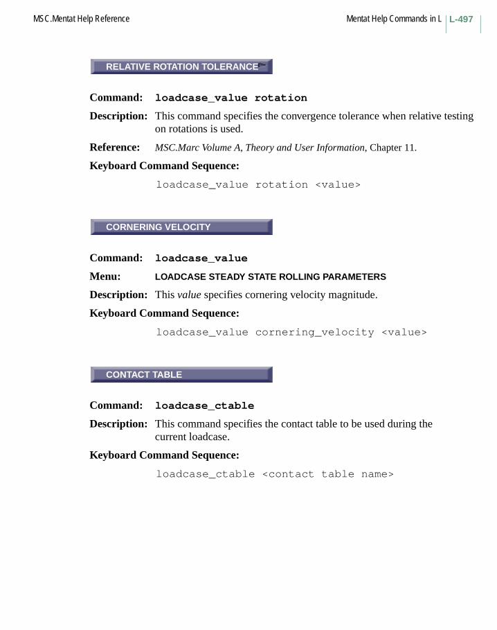
L-497MSC.Mentat Help Reference Mentat Help Commands in L
RELATIVE ROTATION TOLERANCE
Command: loadcase_value rotation
Description: This command specifies the convergence tolerance when relative testing on rotations is used.
Reference: MSC.Marc Volume A, Theory and User Information, Chapter 11.
Keyboard Command Sequence:
loadcase_value rotation <value>
CORNERING VELOCITY
Command: loadcase_value
Menu: LOADCASE STEADY STATE ROLLING PARAMETERS
Description: This value specifies cornering velocity magnitude.
Keyboard Command Sequence:
loadcase_value cornering_velocity <value>
CONTACT TABLE
Command: loadcase_ctable
Description: This command specifies the contact table to be used during the current loadcase.
Keyboard Command Sequence:
loadcase_ctable <contact table name>
RELATIVE ROTATION TOLERANCE
CORNERING VELOCITY
CONTACT TABLE

Mentat Help Commands in L MSC.Mentat Help ReferenceL-498
AUTOMATIC TIME STEP CUT BACK
Command: loadcase_option time_cut
Description: This command specifies the option of automatically reducing the time step and start over from the beginning of the current increment.
This will be done when one of the following things happens during an increment and the analysis would otherwise stop if this option is not activated:
– convergence could not be obtained– one or more elements go inside out– a node slides off the end of a rigid body in a contact analysis
Each time the step is cut back the time step is divided by two. The cut-back is repeated if necessary until a converged solution is obtained or the maximum number of times this is allowed to be done is reached, as specified with the # CUT BACKS ALLOWED option.
With the multi-criteria adaptive stepping procedure (auto step), a cut-back is also done when a user specified desired number of recycles is exceeded or a user specified physical criterion is violated. This option should always be turned on when used with the multi-criteria adaptive scheme, otherwise the time step is not allowed to decrease.
A backup of the data needed to start the increment from the beginning again is kept in memory (or on disk if the OUT-OF-CORE ELEMENT STORAGE (elsto) option is used or if memory could not be allocated).
In a fixed time stepping procedure, subincrements are performed until an increment is completed. Thus, the user specified number of increments and step sizes are preserved.
In an adaptive procedure, the time step is modified when a cut back occurs.
Keyboard Command Sequence:
loadcase_option time_cut:<on/off>
AUTOMATIC TIME STEP CUT BACK
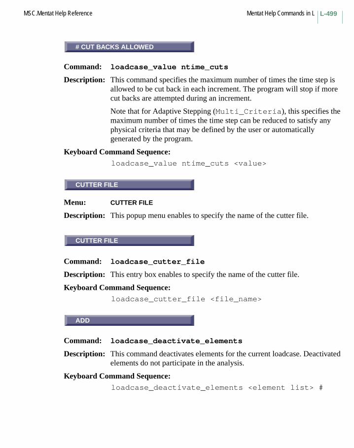
L-499MSC.Mentat Help Reference Mentat Help Commands in L
# CUT BACKS ALLOWED
Command: loadcase_value ntime_cuts
Description: This command specifies the maximum number of times the time step is allowed to be cut back in each increment. The program will stop if more cut backs are attempted during an increment.
Note that for Adaptive Stepping (Multi_Criteria), this specifies the maximum number of times the time step can be reduced to satisfy any physical criteria that may be defined by the user or automatically generated by the program.
Keyboard Command Sequence: loadcase_value ntime_cuts <value>
CUTTER FILE
Menu: CUTTER FILE
Description: This popup menu enables to specify the name of the cutter file.
CUTTER FILE
Command: loadcase_cutter_file
Description: This entry box enables to specify the name of the cutter file.
Keyboard Command Sequence:loadcase_cutter_file <file_name>
ADD
Command: loadcase_deactivate_elements
Description: This command deactivates elements for the current loadcase. Deactivated elements do not participate in the analysis.
Keyboard Command Sequence: loadcase_deactivate_elements <element list> #
# CUT BACKS ALLOWED
CUTTER FILE
CUTTER FILE
ADD

Mentat Help Commands in L MSC.Mentat Help ReferenceL-500
DESIRED # RECYCLES/INCREMENT
Command: loadcase_value desired
Description: This command sets the desired number of recycles (iterations) for the current loadcase.
If the number of recycles in the previous increment is larger than the desired number, the time step is scaled down in an attempt to arrive at the desired number of recycles.
Keyboard Command Sequence:
loadcase_value desired <value>
INITIAL FRACTION
Command: loadcase_value initfraction
Description: This command sets the initial fraction of total load in the current loadcase that is applied initially.
This load increment then can be modified based on the convergence behavior during the current and previous increments.
Keyboard Command Sequence:
loadcase_value initfraction <value>
MAXIMUM FRACTION
Command: loadcase_value maxfraction
Description: This command sets the maximum fraction of total load in the current loadcase that can be applied in each increment.
Keyboard Command Sequence:
loadcase_value maxfraction <value>
DESIRED # RECYCLES/INCREMENT
INITIAL FRACTION
MAXIMUM FRACTION

L-501MSC.Mentat Help Reference Mentat Help Commands in L
MAX LOAD STEP MULTIPLIER
Command: loadcase_value maxmultiplier
Description: This command sets the maximum load step multiplier.
This value is used when the time step is increased. The time step of the next increment is increased when the quotient of convergence ratio and convergence tolerance in cycle one is less than 0.9.
Keyboard Command Sequence:
loadcase_value maxmultiplier <value>
loadcase_equil_minmult
Command: loadcase_value minmultiplier
Description: This command sets the minimum load step multiplier.
This value is used when the time step is decreased. The time step of the next increment is decreased when the number of recycles is larger than the desired number of recycles or if the quotient of convergence ratio and convergence tolerance in cycle one is greater than 2.
Keyboard Command Sequence:
loadcase_value minmultiplier <value>
loadcase_equil_mintime
Command: loadcase_value mintstep
Description: This command sets the minimum allowed time step in the current loadcase.
Keyboard Command Sequence:
loadcase_value mintstep <value>
MAX LOAD STEP MULTIPLIER
MIN LOAD STEP MULTIPLIER
loadcase_equil_mintime

Mentat Help Commands in L MSC.Mentat Help ReferenceL-502
PARAMETERS
Menu: PARAMETERS
Description: This menu contains commands for setting parameters for the equilibrium based load stepping method.
# STEPS
Command: loadcase_value nsteps
Description: This command is used to define the number of steps (increments) to use in the current loadcase if a fixed time stepping procedure is used.
Keyboard Command Sequence: loadcase_value nsteps <value>
GRADUAL FRICTION
Command: loadcase_option
Description: If the gradual friction is turned on, friction coefficient increases gradually from 0 to the final value within the loadcase, based on the time increment. In the case only solution at the end of the loadcase is physically meaningful.
This may enhance stability of the analysis, especially for the transition periods from standstill to rolling, and from brake to traction.
Keyboard Command Sequence: loadcase_option gradual_friction <on/off>
LOADCASE STEADY STATE ROLLING PARAMETERS
Command: loadcase_value
Description: This Value specifies ground velocity_x magnitude.
Keyboard Command Sequence: loadcase_value ground_velocity_x <value>
PARAMETERS
# STEPS
GRADUAL FRICTION
LOADCASE STEADY STATE ROLLING
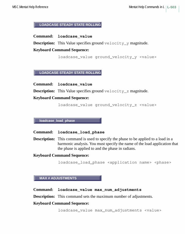
L-503MSC.Mentat Help Reference Mentat Help Commands in L
LOADCASE STEADY STATE ROLLING PARAMETERS
Command: loadcase_value
Description: This Value specifies ground velocity_y magnitude.
Keyboard Command Sequence:
loadcase_value ground_velocity_y <value>
LOADCASE STEADY STATE ROLLING PARAMETERS
Command: loadcase_value
Description: This Value specifies ground velocity_z magnitude.
Keyboard Command Sequence:
loadcase_value ground_velocity_z <value>
loadcase_load_phase
Command: loadcase_load_phase
Description: This command is used to specify the phase to be applied to a load in a harmonic analysis. You must specify the name of the load application that the phase is applied to and the phase in radians.
Keyboard Command Sequence:
loadcase_load_phase <application name> <phase>
MAX # ADJUSTMENTS
Command: loadcase_value max_num_adjustments
Description: This command sets the maximum number of adjustments.
Keyboard Command Sequence:
loadcase_value max_num_adjustments <value>
LOADCASE STEADY STATE ROLLING
LOADCASE STEADY STATE ROLLING
loadcase_load_phase
MAX # ADJUSTMENTS

Mentat Help Commands in L MSC.Mentat Help ReferenceL-504
MAX # INCREMENTS
Command: loadcase_value maxinc
Description: This command sets the maximum number of increments that is allowed in the current loadcase.
Keyboard Command Sequence:
loadcase_value maxinc <value>
Another Button with the same description:
MAX # INCREMENTS IN LOADCASE
AUTOMATIC CRITERIA
Command: loadcase_option automatic_crit
Description: This command sets the option for automatic physical criteria.
If the option is active, the analysis will augment the user’s physical criteria if appropriate. Automatic criteria are only added if there are no competing user criteria.
At present, 4 physical criteria are added automatically by the solver for mechanical / coupled analysis:
– Total strain increment for any large displacement analysis < 50%
– Plastic strain increment for large strain,large displacement analysis < 10%
– For explicit creep analysis,• normalized creep strain increment = 0.5• normalized stress increment = 0.5
– Stress increment associated with temperature changes < 50% of total stress
Keyboard Command Sequence:
loadcase_option automatic_crit:<on,off>
MAX # INCREMENTS
AUTOMATIC CRITERIA

L-505MSC.Mentat Help Reference Mentat Help Commands in L
STRAIN INCREMENT
Command: loadcase_optionmulti_crit_<n>
Description: These commands are used to select the criteria to use for controlling the time step. These buttons are available under the UNDER DEFINED CRITERIA menu associated with the PARAMETERS button for MULTI-CRITERIA.
The time step is reduced during the equilibrium iterations if the increment in any of the selected quantity is larger than the user defined allowed increment. Note that <n> is s value from 1 to 4.
If the TREAT CRITERIA AS TARGETS option is used, the time step for the next increment will be increased to try to reach the value of the least critical criterion.
The factors with which the time step can be changed are limited by the minimum and maximum step ratios.
The limits and ranges for which the limits are valid are defined under the respective PARAMETER menu of each criterion.
Keyboard Command Sequence:
loadcase_optionmulti_crit_<n>:<strain/pl_strain etc.>
Other Buttons with the same description:
CREEP STRAIN INCREMENTDISPLACEMENT INCREMENTNORMALIZED CREEP STRAIN INCREMPLASTIC STRAIN INCREMENTROTATION INCREMENTSTRAIN ENERGY INCREMENTSTRESS INCREMENTTEMPERATURE INCREMENT
STRAIN INCREMENT

Mentat Help Commands in L MSC.Mentat Help ReferenceL-506
STRAIN INC. ALLOWED
Command: loadcase_value mc_dely1_<n>
Description: This group of buttons are used for setting the maximum allowed increment of the current criterion.
The group of buttons have the text 1,2,3,4, and are located in the USER-DEFINED CRITERIA/STRAIN INCREMENT/PARAMETER menu. Note that <n> is a value from 1 to 4.
Other groups of buttons with the same description:
PLASTIC STRAIN ALLOWEDCREEP STRAIN ALLOWEDSTRESS INCR. ALLOWEDNORMALIZED STRESS ALLOWEDSTRAIN ENERGY ALLOWEDSTATE VARIABLE ALLOWEDDISPLACEMENT ALLOWEDROTATION INCR. ALLOWEDTEMPERATURE ALLOWED
PARAMETERS
Menu: PARAMETER
Description: This menu contains commands for defining the maximum value of the increment for each criterion.
Both the limits and the ranges for which the limits are valid is defined.
STRAIN RANGE LOWER BOUND
Command: loadcase_value mc_xmax1_<n>
Description: This group of buttons are used for setting the lower bound for which the limits for the current criterion is to be applied.
Thus, it is possible to have different tolerances for different values of the criterion used.
STRAIN INC. ALLOWED
PARAMETERS
STRAIN RANGE LOWER BOUND
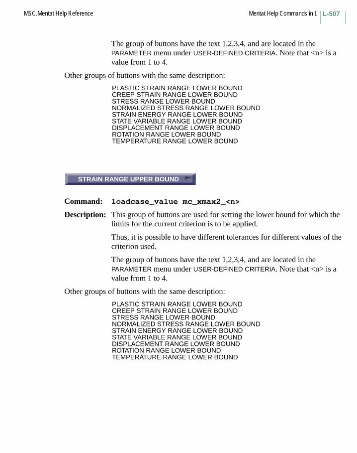
L-507MSC.Mentat Help Reference Mentat Help Commands in L
The group of buttons have the text 1,2,3,4, and are located in the PARAMETER menu under USER-DEFINED CRITERIA. Note that <n> is a value from 1 to 4.
Other groups of buttons with the same description:
PLASTIC STRAIN RANGE LOWER BOUNDCREEP STRAIN RANGE LOWER BOUNDSTRESS RANGE LOWER BOUNDNORMALIZED STRESS RANGE LOWER BOUNDSTRAIN ENERGY RANGE LOWER BOUNDSTATE VARIABLE RANGE LOWER BOUNDDISPLACEMENT RANGE LOWER BOUND ROTATION RANGE LOWER BOUNDTEMPERATURE RANGE LOWER BOUND
STRAIN RANGE UPPER BOUND
Command: loadcase_value mc_xmax2_<n>
Description: This group of buttons are used for setting the lower bound for which the limits for the current criterion is to be applied.
Thus, it is possible to have different tolerances for different values of the criterion used.
The group of buttons have the text 1,2,3,4, and are located in the PARAMETER menu under USER-DEFINED CRITERIA. Note that <n> is a value from 1 to 4.
Other groups of buttons with the same description:
PLASTIC STRAIN RANGE LOWER BOUNDCREEP STRAIN RANGE LOWER BOUNDSTRESS RANGE LOWER BOUNDNORMALIZED STRESS RANGE LOWER BOUNDSTRAIN ENERGY RANGE LOWER BOUNDSTATE VARIABLE RANGE LOWER BOUNDDISPLACEMENT RANGE LOWER BOUND ROTATION RANGE LOWER BOUNDTEMPERATURE RANGE LOWER BOUND
STRAIN RANGE UPPER BOUND
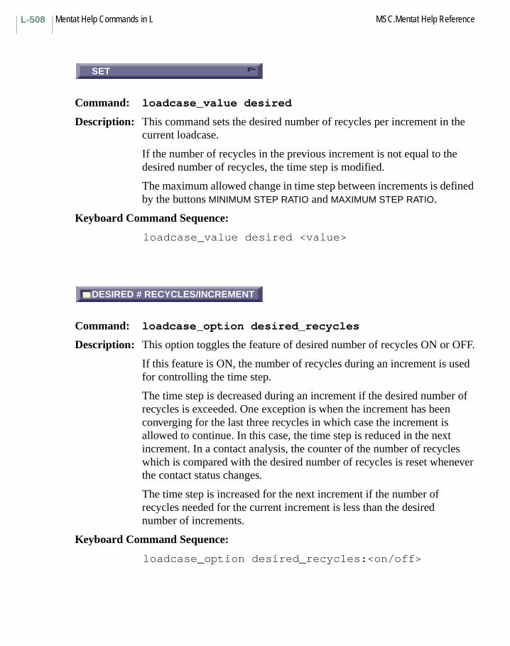
Mentat Help Commands in L MSC.Mentat Help ReferenceL-508
SET
Command: loadcase_value desired
Description: This command sets the desired number of recycles per increment in the current loadcase.
If the number of recycles in the previous increment is not equal to the desired number of recycles, the time step is modified.
The maximum allowed change in time step between increments is defined by the buttons MINIMUM STEP RATIO and MAXIMUM STEP RATIO.
Keyboard Command Sequence:
loadcase_value desired <value>
DESIRED # RECYCLES/INCREMENT
Command: loadcase_option desired_recycles
Description: This option toggles the feature of desired number of recycles ON or OFF.
If this feature is ON, the number of recycles during an increment is used for controlling the time step.
The time step is decreased during an increment if the desired number of recycles is exceeded. One exception is when the increment has been converging for the last three recycles in which case the increment is allowed to continue. In this case, the time step is reduced in the next increment. In a contact analysis, the counter of the number of recycles which is compared with the desired number of recycles is reset whenever the contact status changes.
The time step is increased for the next increment if the number of recycles needed for the current increment is less than the desired number of increments.
Keyboard Command Sequence:
loadcase_option desired_recycles:<on/off>
SET
DESIRED # RECYCLES/INCREMENT
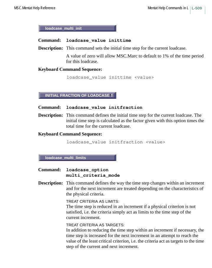
L-509MSC.Mentat Help Reference Mentat Help Commands in L
loadcase_multi_init
Command: loadcase_value inittime
Description: This command sets the initial time step for the current loadcase.
A value of zero will allow MSC.Marc to default to 1% of the time period for this loadcase.
Keyboard Command Sequence:
loadcase_value inittime <value>
INITIAL FRACTION OF LOADCASE T
Command: loadcase_value initfraction
Description: This command defines the initial time step for the current loadcase. The initial time step is calculated as the factor given with this option times the total time for the current loadcase.
Keyboard Command Sequence:
loadcase_value initfraction <value>
loadcase_multi_limits
Command: loadcase_optionmulti_criteria_mode
Description: This command defines the way the time step changes within an increment and for the next increment are treated depending on the characteristics of the physical criteria.
TREAT CRITERIA AS LIMITS:The time step is reduced in an increment if a physical criterion is not satisfied, i.e. the criteria simply act as limits to the time step of the current increment.
TREAT CRITERIA AS TARGETS:In addition to reducing the time step within an increment if necessary, the time step is increased for the next increment in an attempt to reach the value of the least critical criterion, i.e. the criteria act as targets to the time step of the current and next increment.
loadcase_multi_init
INITIAL FRACTION OF LOADCASE T
loadcase_multi_limits

Mentat Help Commands in L MSC.Mentat Help ReferenceL-510
The TARGETS option has another important use: in dynamic problems with the implicit Newmark-Beta or SSH operators, this option can be set if one does not want the auto step algorithm to check the time step for integration errors. This may be useful for high-noise/contact dynamic problems.
Keyboard Command Sequence:
loadcase_optionmulti_criteria_mode:<limit/target>
MAXIMUM FRACTION OF LOADCASE T
Command: loadcase_value maxfraction
Description: This command defines the maximum time step for the current loadcase. The maximum time step is calculated as the factor given with this option times the total time for the current loadcase.
The maximum time step puts a limit on the size of the time step. It can be used to avoid very large time steps.
Keyboard Command Sequence:
loadcase_value maxfraction <value>
MAXIMUM # STEPS
Command: loadcase_value maxnsteps
Description: This command sets the maximum number of steps (increments) that is allowed during this loadcase.
If set to zero, a value of 10 times the inverse of the inital fraction of loadcase time will be used.
Keyboard Command Sequence:
loadcase_value maxnsteps <value>
MAXIMUM FRACTION OF LOADCASE T
MAXIMUM # STEPS

L-511MSC.Mentat Help Reference Mentat Help Commands in L
MAXIMUM STEP RATIO
Command: loadcase_value max_step_ratio
Description: This command sets the largest factor with which the time step is allowed to increase in the next increment due to a physical criterion. This factor is only significant when the TREAT CRITERIA AS TARGETS option is used.
Keyboard Command Sequence:
loadcase_value max_step_ratio <value>
loadcase_multi_maxtime
Command: loadcase_value maxtime
Description: This command sets the maximum allowed time step.
Defaults to the total time.
Keyboard Command Sequence:
loadcase_value maxtime <value>
MINIMUM FRACTION OF LOADCASE T
Command: loadcase_value minfraction
Description: This command defines the minimum time step for the current loadcase. The minimum time step is calculated as the factor given with this option times the total time for the current loadcase.
If the time step is decreased to below the minimum time step the program will stop, unless the quasi-static inertial damping option is used.
Keyboard Command Sequence:
loadcase_value minfraction <value>
MAXIMUM STEP RATIO
loadcase_multi_maxtime
MINIMUM FRACTION OF LOADCASE T
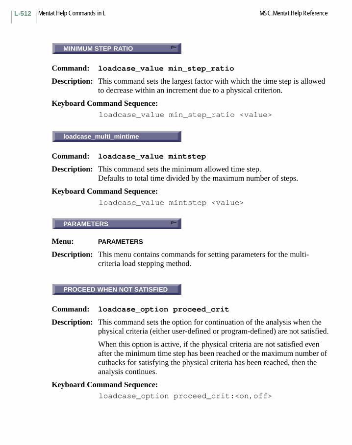
Mentat Help Commands in L MSC.Mentat Help ReferenceL-512
MINIMUM STEP RATIO
Command: loadcase_value min_step_ratio
Description: This command sets the largest factor with which the time step is allowed to decrease within an increment due to a physical criterion.
Keyboard Command Sequence: loadcase_value min_step_ratio <value>
loadcase_multi_mintime
Command: loadcase_value mintstep
Description: This command sets the minimum allowed time step.Defaults to total time divided by the maximum number of steps.
Keyboard Command Sequence: loadcase_value mintstep <value>
PARAMETERS
Menu: PARAMETERS
Description: This menu contains commands for setting parameters for the multi-criteria load stepping method.
PROCEED WHEN NOT SATISFIED
Command: loadcase_option proceed_crit
Description: This command sets the option for continuation of the analysis when the physical criteria (either user-defined or program-defined) are not satisfied.
When this option is active, if the physical criteria are not satisfied even after the minimum time step has been reached or the maximum number of cutbacks for satisfying the physical criteria has been reached, then the analysis continues.
Keyboard Command Sequence:loadcase_option proceed_crit:<on,off>
MINIMUM STEP RATIO
loadcase_multi_mintime
PARAMETERS
PROCEED WHEN NOT SATISFIED

L-513MSC.Mentat Help Reference Mentat Help Commands in L
TIME STEP SCALE FACTOR
Command: loadcase_value scale_step
Description: This command defines the scale factor that is used for scaling the time step based upon the desired number of recycles.
Description: If the desired number of recycles is exceeded in an increment, the time step is decreased using a cutback and the increment is repeated. The cutback factor should be less than or equal to (1.0/scale factor). As the number of cutbacks increase in an increment, an automatic algorithm is used to reduce the time step more aggressively such that the minimum allowed time step is reached within a reasonable number of cutbacks.
If the number of recycles needed in an increment is less than the desired number, the time step size for the next increment is multiplied by this factor.
Keyboard Command Sequence:
loadcase_value scale_step <value>
USER-DEFINED CRITERIA
Command: loadcase_option multi_crit_n(n = criterion no. from 1 to 12)
Description: This button enables access to user defined physical criteria. Both element based criteria (stresses, strains, etc.) and nodal based criteria (displacements, rotations, etc.) can be specified. The criteria can be specified for the entire set of finite element entities or for specific sets of entities.
These criteria can be augmented by automatic physical criteria that the program adds at run-time.
Keyboard Command Sequence:
loadcase_option multi_crit_n: <on/off>
TIME STEP SCALE FACTOR
USER-DEFINED CRITERIA
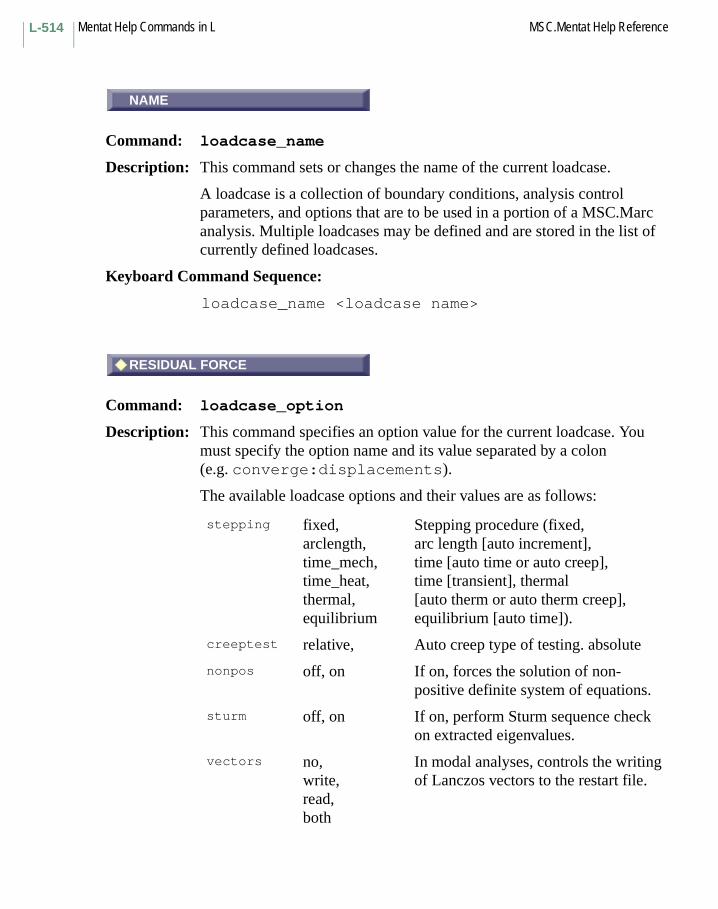
Mentat Help Commands in L MSC.Mentat Help ReferenceL-514
NAME
Command: loadcase_name
Description: This command sets or changes the name of the current loadcase.
A loadcase is a collection of boundary conditions, analysis control parameters, and options that are to be used in a portion of a MSC.Marc analysis. Multiple loadcases may be defined and are stored in the list of currently defined loadcases.
Keyboard Command Sequence:
loadcase_name <loadcase name>
RESIDUAL FORCE
Command: loadcase_option
Description: This command specifies an option value for the current loadcase. You must specify the option name and its value separated by a colon (e.g. converge:displacements).
The available loadcase options and their values are as follows:
stepping fixed,arclength,time_mech,time_heat,thermal,equilibrium
Stepping procedure (fixed,arc length [auto increment],time [auto time or auto creep], time [transient], thermal[auto therm or auto therm creep], equilibrium [auto time]).
creeptest relative, Auto creep type of testing. absolute
nonpos off, on If on, forces the solution of non-positive definite system of equations.
sturm off, on If on, perform Sturm sequence check on extracted eigenvalues.
vectors no,write,read,both
In modal analyses, controls the writing of Lanczos vectors to the restart file.
NAME
RESIDUAL FORCE
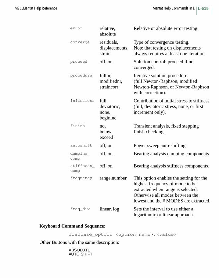
L-515MSC.Mentat Help Reference Mentat Help Commands in L
Keyboard Command Sequence:
loadcase_option <option name>:<value>
Other Buttons with the same description:
ABSOLUTEAUTO SHIFT
error relative,absolute
Relative or absolute error testing.
converge residuals,displacements,strain
Type of convergence testing.Note that testing on displacements always requires at least one iteration.
proceed off, on Solution control: proceed if not converged.
procedure fullnr,modifiednr,straincorr
Iterative solution procedure(full Newton-Raphson, modified Newton-Raphson, or Newton-Raphson with correction).
initstress full,deviatoric,none,begininc
Contribution of initial stress to stiffness (full, deviatoric stress, none, or first increment only).
finish no,below,exceed
Transient analysis, fixed stepping finish checking.
autoshift off, on Power sweep auto-shifting.
damping_ comp
off, on Bearing analysis damping components.
stiffness_ comp
off, on Bearing analysis stiffness components.
frequency range,number This option enables the setting for the highest frequency of mode to be extracted when range is selected. Otherwise all modes between the lowest and the # MODES are extracted.
freq_div linear, log Sets the interval to use either a logarithmic or linear approach.
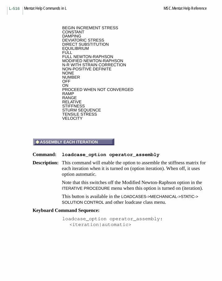
Mentat Help Commands in L MSC.Mentat Help ReferenceL-516
BEGIN INCREMENT STRESSCONSTANTDAMPINGDEVIATORIC STRESSDIRECT SUBSTITUTIONEQUILIBRIUMFULLFULL NEWTON-RAPHSONMODIFIED NEWTON-RAPHSONN-R WITH STRAIN CORRECTIONNON-POSITIVE DEFINITENONENUMBEROFFONPROCEED WHEN NOT CONVERGEDRAMPRANGERELATIVESTIFFNESSSTURM SEQUENCETENSILE STRESSVELOCITY
ASSEMBLY EACH ITERATION
Command: loadcase_option operator_assembly
Description: This command will enable the option to assemble the stiffness matrix for each iteration when it is turned on (option iteration). When off, it uses option automatic.
Note that this switches off the Modified Newton-Raphson option in the ITERATIVE PROCEDURE menu when this option is turned on (iteration).
This button is available in the LOADCASES->MECHANICAL->STATIC-> SOLUTION CONTROL and other loadcase class menu.
Keyboard Command Sequence:
loadcase_option operator_assembly: <iteration|automatic>
ASSEMBLY EACH ITERATION
L-517MSC.Mentat Help Reference Mentat Help Commands in L
UNCHANGED
Command: loadcase_option post
Description: This command will allow for altering the increment interval at which data is written to the post file.
UNCHANGED:The post data for this loadcase will be written at the same interval as the previous loadcase.
INCREMENT FREQUENCY:The post data will be written to the post file at the interval specified using the SET button.
NONE:No post data will be written for this loadcase.
This option is available in the LOADCASES->MECHANICAL->STATIC-> LOADCASE RESULTS menu.
Keyboard Command Sequence:
loadcase_option post:<unchanged|freq|none>
Other Buttons with the same description:
INCREMENT FREQUENCYSETNONE
RESULTS AT FIXED TIME INTERVAL
Command: loadcase_option post_file_method
Description: This command sets the option for post file output frequency.
RESULTS AT FIXED TIME INTERVALS
If this option is active, results will be written to the post file at equally spaced intervals in time. Specify the number of states with the # POST FILE STATES button. The time step will be temporarily adjusted to exactly reach the times for post output.
If the option is not active, the increment based output frequency defined in the JOBS menu is used.
UNCHANGED
RESULTS AT FIXED TIME INTERVAL

Mentat Help Commands in L MSC.Mentat Help ReferenceL-518
Keyboard Command Sequence:
loadcase_optionpost_file_method:<time/increment>
# POST FILE STATES
Command: loadcase_value num_post
Description: This command sets the number of states that are written to the post file if the option RESULTS AT FIXED TIME INTERVALS is active.
Keyboard Command Sequence:
loadcase_value num_post <value>
GRADUAL
Command: loadcase_option contact_release
Description: This command defines the way the nodal forces are removed in the contact body release option.
IMMEDIATE the forces are removed at the start of the increment.
GRADUAL the forces are removed gradually.
Keyboard Command Sequence:
loadcase_option contact_release:<immediate/gradual>
Another Button with the same description:
IMMEDIATE
# POST FILE STATES
GRADUAL
L-519MSC.Mentat Help Reference Mentat Help Commands in L
RESET
Command: loadcase_reset
Description: This command resets loadcase parameters and options to their default values.
Keyboard Command Sequence:
loadcase_reset
BEGIN INCREMENT STRESS
Command: loadcase_option initstress
Description: This option controls the contribution of the initial stress matrix (geometric stiffness matrix) to the tangent stiffness matrix.
By default, the (stress dependent) initial stress matrix gives a full contribution to the tangent stiffness matrix. In certain cases, it can be advantageous not to have a full contribution. This influences the convergence behavior of the solution, but not the accuracy of the converged value.
The options are:
FULL Full contribution of initial stress matrix.
NONE No contribution of initial stress matrix.
DEVIATORIC STRESS
Only deviatoric stresses contribute to the initial stress matrix. This is often useful in rubber analysis, when the volumetric stresses are large. The contribution of volumetric stresses can be varied linearly with use of a factor ft. For ft equal to one, it gives no contribution of volumetric stresses (default), and ft equal to zero gives full contribution. The factor ft can be set in the NUMERICAL PREFERENCES menu in the different loadcase menus. It is called MEAN STRESS SUBTRACTION FACTOR for INIT. STRESS.
RESET
BEGIN INCREMENT STRESS

Mentat Help Commands in L MSC.Mentat Help ReferenceL-520
Reference: MSC.Marc Volume C: Program Input, Chapter 3.
Keyboard Command Sequence:
loadcase_option initstress:<none/full/deviatoric/begininc>
Other Buttons with the same description:
DEVIATORIC STRESSFULLNONETENSILE STRESS
FULL NEWTON-RAPHSON
Command: loadcase_option procedure
Description: This command is used to choose the solution procedure to use in the equilibrium iterations in a nonlinear static analysis.
The FULL NEWTON-RAPHSON method is the default procedure. The tangent stiffness matrix is reformulated for each iteration (recycle).
In the MODIFIED NEWTON-RAPHSON method, the tangent stiffness matrix is formulated only once per increment. This leads to lower cost, but possibly slower convergence.
NEWTON-RAPHSON WITH STRAIN CORRECTION is a variant of the full Newton-Raphson method. It uses a special formulation for how the strains enter the tangent stiffness matrix and load vector and is appropriate for shell and beam problems in which rotations are large, but membrane stresses are small. The use of this method can lead to a more accurate solution for a given load step size.
The secant method is also available in Marc, but not through Mentat. To use this method, edit the MSC.Marc input file. See MSC.Marc Volume C, Chapter 3: page 3-143.
BEGIN INCREMENT STRESS
The stresses at the beginning of the increment are used for the initial stress matrix and not the stresses at the last iteration.
TENSILE STRESS Only tensile stresses contribute to the initial stress matrix.
FULL NEWTON-RAPHSON
L-521MSC.Mentat Help Reference Mentat Help Commands in L
The full Newton-Raphson method can be expensive for large, three-dimensional problem when a direct solver is used. The modified Newton-Raphson method is effective for large, mildly nonlinear problems. When an iterative solver is used, simple back substitution is not possible which makes this method ineffective. In such cases, the full Newton-Raphson method should be used instead.
Reference: MSC.Marc Volume A: Theory and User Information, Chapter 11.
Keyboard Command Sequence:
loadcase_option procedure:<fullnr/modifiednr/straincorr>
Other Buttons with the same description:
MODIFIED NEWTON-RAPHSONN-R WITH STRAIN CORRECTION
MAX # INCREMENTS IN JOB
Command: loadcase_value maxjobinc
Description: This command is used to set the maximum number of increments that are allowed during this job. The job stops if this number is reached. The default number used by MSC.Marc Mentat is 99999.
This is usually used to stop the run when restart is being used. This option is ignored if the ELASTIC option is being used (set in the JOBS menu). Then all loadcases are analyzed.
Note: The number of increments can be very large in a dynamic analysis, in particular with the explicit operator.
Keyboard Command Sequence:
loadcase_value maxjobinc <value>
MAX # INCREMENTS IN JOB
Mentat Help Commands in L MSC.Mentat Help ReferenceL-522
MAX # RECYCLES
Command: loadcase_value maxrec
Description: This command sets the maximum number of recycles (iterations) that is allowed during the equilibrium iteration in an increment of a nonlinear analysis. The job stops if this number of recycles is reached.
The default in MSC.Marc Mentat is 10. This number must sometimes be increased for problems which show slow convergence, in particular a rigid-plastic flow analysis. If a large number of recycles are needed, it is usually better to use smaller load increments or use automatic load stepping.
Keyboard Command Sequence:
loadcase_value maxrec <value>
MIN # RECYCLES
Command: loadcase_value minrec
Description: This command sets the minimum number of recycles (iterations) that is performed during the equilibrium iteration in an increment of a nonlinear analysis.
The default is 0. This is used to force a given number of recycles to take place in all increments.
Keyboard Command Sequence:
loadcase_value minrec <value>
MAX # RECYCLES
MIN # RECYCLES
L-523MSC.Mentat Help Reference Mentat Help Commands in L
NON-POSITIVE DEFINITE
Command: loadcase_option nonpos
Description: If this option is turned on, the solution of a nonpositive definite system is forced.
It is only recommended to use this option when automatic load stepping with the arc-length methods is used in post-buckling analysis. It should not be used in a static analysis to remove a rigid body motion.
Keyboard Command Sequence:
loadcase_option nonpos:<on/off>
PROCEED WHEN NOT CONVERGED
Command: loadcase_option proceed
Description: This option is used to specify that the program should proceed with the next increment even if convergence is not obtained within the current increment.
If the maximum number of recycles is reached without convergence, a warning is given and the analysis is continued.
This option is in general not recommended.
Keyboard Command Sequence:
loadcase_option proceed:<on/off>
LOADCASE STEADY STATE ROLLING PARAMETERS
Command: loadcase_value
Description: This value specifies spinning velocity magnitude.
Keyboard Command Sequence:
loadcase_value spinning_velocity <value>
NON-POSITIVE DEFINITE
PROCEED WHEN NOT CONVERGED
LOADCASE STEADY STATE ROLLING

Mentat Help Commands in L MSC.Mentat Help ReferenceL-524
LOADCASE STEADY STATE ROLLING PARAMETERS
Command: loadcase_option
Description: This option is used to set type of input of steady state rolling parameters.
If spin_velocity is selected, spinning velocity controls the analysis.
If torque is selected, torque controls the analysis.
Keyboard Command Sequence:
loadcase_option ss_rolling_input:<spin_velocity/torque>
LOADCASE STEADY STATE ROLLING PARAMETERS
Command: loadcase_value
Description: This command sets the tolerance. It is considered converged if the ratio of torque change at current iteration over the maximum torque is less than the tolerance.
Keyboard Command Sequence:
loadcase_value ss_rolling_tolerance <value>
ARC LENGTH
Command: loadcase_option stepping:arclength
Description: This command is used to specify that the arc-length based load stepping scheme is to be used.
This procedure uses a so-called arc-length method for controlling the load step. It is capable of handling unstable deformation such as snap-through and collapse analysis.
In an arc-length method, the size of the load increment is limited by an extra constraint. This constraint is defined such that the length of the load increment is equal to an arc-length. The definition of this arc-length is what differs between the different methods. With this formulation, the prescribed load is allowed to both increase and decrease so that unstable
LOADCASE STEADY STATE ROLLING
LOADCASE STEADY STATE ROLLING
ARC LENGTH
L-525MSC.Mentat Help Reference Mentat Help Commands in L
solution paths can be followed. The solution to the constraint equation gives the new solution increment to apply.
The arc-length (and thus the step size) is initially set as a fraction of the total load during the loadcase. It can change in size based on the number of recycles needed in a previous increment compared with a user-defined desired number of recycles. The size of the load step can also be limited in order to avoid problems when the degree of nonlinearity in the problem changes.
Corresponds to MSC.Marc command auto increment.
Keyboard Command Sequence:
loadcase_option stepping:arclength
QUASI-STATIC INERTIAL DAMPING
Command: loadcase_stepping_damp_it
Description: This toggle when turned on will provide inertial damping for static contact problems. Otherwise, no inertial damping is used which is the default.
The damping becomes active only if the minimum time step is reached and is turned off again if the time step is increased above the minimum time step.
Keyboard Command Sequence:
loadcase_stepping_damp_itloadcase_stepping_damp_it:off
QUASI-STATIC INERTIAL DAMPING
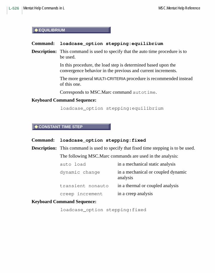
Mentat Help Commands in L MSC.Mentat Help ReferenceL-526
EQUILIBRIUM
Command: loadcase_option stepping:equilibrium
Description: This command is used to specify that the auto time procedure is to be used.
In this procedure, the load step is determined based upon the convergence behavior in the previous and current increments.
The more general MULTI-CRITERIA procedure is recommended instead of this one.
Corresponds to MSC.Marc command autotime.
Keyboard Command Sequence:
loadcase_option stepping:equilibrium
CONSTANT TIME STEP
Command: loadcase_option stepping:fixed
Description: This command is used to specify that fixed time stepping is to be used.
The following MSC.Marc commands are used in the analysis:
auto load in a mechanical static analysis
dynamic change in a mechanical or coupled dynamic analysis
transient nonauto in a thermal or coupled analysis
creep increment in a creep analysis
Keyboard Command Sequence:
loadcase_option stepping:fixed
EQUILIBRIUM
CONSTANT TIME STEP

L-527MSC.Mentat Help Reference Mentat Help Commands in L
MULTI-CRITERIA
Command: loadcase_option stepping:multicriteria
Description: This command is used to specify that the general adaptive multi-criteria load stepping scheme is to be used.
The load step can be adjusted based upon the number of recycles needed to reach equilibrium. There is also an option to control the time step based upon a user specified allowed increment of stress, strain, or other criteria.
Corresponds to MSC.Marc command autostep.
Keyboard Command Sequence:
loadcase_option stepping:multicriteria
TEMPERATURE
Command: loadcase_option stepping:thermal
Description: This command is used to specify that the temperature driven load stepping scheme is to be used.
This procedure is used in a thermally loaded mechanical analysis where the thermal load is obtain from a previous thermal analysis. The temperatures are read from the post file of the previous analysis.
Corresponds to MSC.Marc command autotherm.
Keyboard Command Sequence:
loadcase_option stepping:thermal
MULTI-CRITERIA
TEMPERATURE

Mentat Help Commands in L MSC.Mentat Help ReferenceL-528
TEMPERATURE
Command: loadcase_option stepping:time_heat
Description: This command is used to specify that the temperature based load stepping scheme is to be used.
This procedure is used in a thermal or coupled analysis where the temperature is used to control the time step.
The target temperature increment is specified as MAX TEMPERATURE CHANGE ALLOWED in the CONVERGENCE TESTING menu.
Corresponds to MSC.Marc command transient.
The more general MULTI-CRITERIA option covers this option and also allows more control over the way the time step is changed.
Keyboard Command Sequence: loadcase_option stepping:time_heat
loadcase_temp_finish
Command: loadcase_option finish
Description: This option is used to stop a transient analysis involving a thermal part if all nodal temperatures are below or exceed the specified finish temperature.
Keyboard Command Sequence: loadcase_option finish:<no/below/exceed>
FINISH TEMPERATURE
Command: loadcase_value temp_finish
Description: This command sets the temperature value used for the finish check option.
Keyboard Command Sequence: loadcase_value temp_finish <value>
TEMPERATURE
loadcase_temp_finish
FINISH TEMPERATURE

L-529MSC.Mentat Help Reference Mentat Help Commands in L
# INCS BETWEEN REASSEMBLY
Command: loadcase_value inc_assemble
Description: This command sets the reassembly interval for element matrices.
This influences the speed of convergence, but not the time step.
Keyboard Command Sequence:
loadcase_value inc_assemble <value>
MAX TEMPERATURE CHANGE
Command: loadcase_value temp_change
Description: This command sets the maximum temperature change that is allowed in each increment.
If the applied temperature is larger than this value, the time increment is subdivided assuming a linear change in temperature during the increment.
The choice of the maximum temperature change should be based on accuracy of nonlinear effects like plasticity, creep, or geometry changes.
Keyboard Command Sequence:
loadcase_value temp_change <value>
MAXIMUM TIME STEP
Command: loadcase_value maxtime
Description: This command sets the maximum time step that is allowed.
The temperature increment is scaled such that the time step is smaller than this value.
Keyboard Command Sequence:
loadcase_value maxtime <value>
# INCS BETWEEN REASSEMBLY
MAX TEMPERATURE CHANGE
MAXIMUM TIME STEP
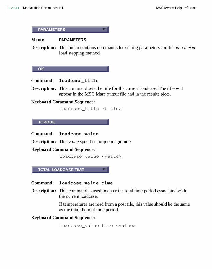
Mentat Help Commands in L MSC.Mentat Help ReferenceL-530
PARAMETERS
Menu: PARAMETERS
Description: This menu contains commands for setting parameters for the auto therm load stepping method.
OK
Command: loadcase_title
Description: This command sets the title for the current loadcase. The title will appear in the MSC.Marc output file and in the results plots.
Keyboard Command Sequence: loadcase_title <title>
TORQUE
Command: loadcase_value
Description: This value specifies torque magnitude.
Keyboard Command Sequence:loadcase_value <value>
TOTAL LOADCASE TIME
Command: loadcase_value time
Description: This command is used to enter the total time period associated with the current loadcase.
If temperatures are read from a post file, this value should be the same as the total thermal time period.
Keyboard Command Sequence:
loadcase_value time <value>
PARAMETERS
OK
TORQUE
TOTAL LOADCASE TIME

L-531MSC.Mentat Help Reference Mentat Help Commands in L
CREEP
Command: loadcase_type
Description: This command sets the type of the current loadcase to the specified type. The type of loadcase that may be used depends on the type of analysis desired.
The valid loadcase types are given below:
Keyboard Command Sequence:
loadcase_type <loadcase type>
Other Buttons with the same description:
BODY APPROACHDYNAMIC HARMONICDYNAMIC MODALDYNAMIC TRANSIENT
Analysis Class Valid Loadcase Types
mechanical static, buckle, creep, dynamic_modal, dynamic_transient, dynamic_harmonic, spectrum, rpflow, contact_approach
heat steady_state, transient_heat
coupled coupled, coupled_creep, coupled_dyn_transient, coupled_rpflow, coupled_cont_approach
joule joule_steady_state, joule_transient
fluid fluid_steady_state, fluid_transient
fluid_thermal fluidtherm_steady, fluidtherm_trans
fluid_solid fluidsolid_steady, fluidsolid_trans
fluid_thermsolid fluidthermsolid_steady, fluidthermsolid_trans
acoustic acoustic_modal, acoustic_transient
bearing bearing
electrostatic electrostatic
magnetostatic magnetostatic
electromagnetic electromagnetic_harmonic, electromagnetic_transient
CREEP

Mentat Help Commands in L MSC.Mentat Help ReferenceL-532
HARMONICMODALQUASI-STATICSPECTRUM RESPONSESTEADY STATETRANSIENT
# FREQUENCIES
Command: loadcase_value
Description: This command sets loadcase parameter values. You must specify the parameter to be set and its value.
Valid loadcase parameters are as follows:
abscurrent, adapg_frequency, angle0,
angle1, angle2, angle3,
angle4, angle5, bcond_pen_mp,
beta, buckle_tol, contribution,
cooling_time, crank_length, creeptime,
cutoff_stress, cycle_time, desired,
displacement, dt_allowed, dt_assemble,
dt_error, eccentricity, fluid_force,
fluid_incomp_pen, fluid_maxforce, fluid_maxvelo,
fluid_minforce, fluid_minvelo, fluid_velo,
force, gamma, high,
inc_assemble, inc_strn_pred_mp, initfraction,
initshift, inittime, limit_angle_2d,
limit_angle_3d, low, max_step_ratio,
maxdisp, maxforce, maxfraction,
maxinc, maxit, maxjobinc,
maxmoment, maxmultiplier, maxnsteps,
maxrec, maxrotation, maxsubinc,
maxtime, mc_dely1_1, mc_dely1_2,
mc_dely1_3, mc_dely1_4, mc_dely1_5,
mc_dely1_7, mc_dely1_8, mc_dely1_9,
mc_dely1_10, mc_dely2_1, mc_dely2_2,
mc_dely2_3, mc_dely2_4, mc_dely2_5,
mc_dely2_7, mc_dely2_8, mc_dely2_9,
mc_dely2_10, mc_dely3_1, mc_dely3_2,
mc_dely3_3, mc_dely3_4, mc_dely3_5,
# FREQUENCIES

L-533MSC.Mentat Help Reference Mentat Help Commands in L
Keyboard Command Sequence:
loadcase_value <parameter label> <value>
Other Buttons with the same description:
# INCREMENTS# INCS BETWEEN REASSEMBLY# MODES# MODES PER SHIFT2-D CONTACT LIMIT ANGLE3-D CONTACT LIMIT ANGLE
mc_dely3_7, mc_dely3_8, mc_dely3_9,
mc_dely3_10, mc_dely4_1, mc_dely4_2,
mc_dely4_3, mc_dely4_4, mc_dely4_5,
mc_dely4_7, mc_dely4_8, mc_dely4_9,
mc_dely4_10, mc_xmax1_1, mc_xmax1_2,
mc_xmax1_3, mc_xmax1_4, mc_xmax1_5,
mc_xmax1_7, mc_xmax1_8, mc_xmax1_9,
mc_xmax1_10, mc_xmax2_1, mc_xmax2_2,
mc_xmax2_3, mc_xmax2_4, mc_xmax2_5,
mc_xmax2_7, mc_xmax2_8, mc_xmax2_9,
mc_xmax2_10, mc_xmax3_1, mc_xmax3_2,
mc_xmax3_3, mc_xmax3_4, mc_xmax3_5,
mc_xmax3_7, mc_xmax3_8, mc_xmax3_9,
mc_xmax3_10, mean_strs_subtr, min_arcl_ratio,
min_step_ratio, mindisp, minforce,
minmoment, minmultiplier, minrec,
minrotation, mintstep, minvelocity,
moment, nfreq, nmodes,
npmodes, nsteps, press_dir_x,
press_dir_y, press_dir_z, press_max_force,
pshigh, relcurrent, rod_length,
rotation, rp_ctff_strn_rt, rp_incomp_pen,
rp_init_strn_rt, shell_drill, shiftmodes,
shiftpar, strain, strain_change,
stress_change, temp_change, temp_finish,
time, time1, time2,
time3, time4, time5,
tolerance, transport_time, vel_def,
vel_in, vel_out, velocity,
voltage, weight_dx, weight_dy,
weight_dz, weight_rx, weight_ry,
weight_rz

Mentat Help Commands in L MSC.Mentat Help ReferenceL-534
ABSOLUTEBOUNDARY CONDITION PENALTY MULCUTOFF STRESS TOLERANCEDESIRED # RECYCLESDYNAMIC CONTACT PROJECTION FACFLUID INCOMPRESSIBILITY PENALTFRACTION OF NODES IN CONTACTHIGHEST FREQUENCYINCREMENTAL STRAIN PREDICTIONINITIAL FRACTIONINITIAL SHIFTINITIAL TIME STEPLOWEST FREQUENCYMAX # INCREMENTSMAX # INCREMENTS IN JOBMAX # ITERATIONSMAX # RECYCLESMAX # SUBINCREMENTSMAX ERROR IN TEMPERATURE ESTIMMAX LOAD STEP MULTIPLIERMAX TEMPERATURE CHANGEMAX TEMPERATURE CHANGE ALLOWEDMAX TEMPERATURE CHANGE BEFOREMAX TIME STEP MULTIPLIERMAXIMUMMAXIMUM ABSOLUTE RESIDUAL FORCMAXIMUM ABSOLUTE VELOCITYMAXIMUM FRACTIONMAXIMUM TIME STEPMEAN STRESS SUBTRACTION FACTORMIN # RECYCLESMIN LOAD STEP MULTIPLIERMIN TIME STEPMIN TIME STEP MULTIPLIERMINIMUMMINIMUM REACTION FORCE CUTOFFMINIMUM VELOCITY CUTOFFNEWMARK-BETA BETA PARAMETERNEWMARK-BETA GAMMA PARAMETERPRE-STRESSRELATIVERELATIVE FORCE TOLERANCERELATIVE VELOCITY TOLERANCERIGID PLASTIC CUTOFF STRAIN RARIGID PLASTIC INCOMPRESSIBILITRIGID PLASTIC INIT. STRAIN RATSHELL ELEMENT DRILLING MODE FASHIFT PARAMETERSINGLE-STEP HOUBOLT GAMMA PARASINGLE-STEP HOUBOLT GAMMA1 PARSTRAIN CHANGE TOLERANCESTRAIN SAMPLING CUTOFFSTRESS CHANGE TOLERANCETARGET STRAIN RATETOLERANCETOTAL CREEP TIMEX DISPLACEMENT WEIGHT FACTOR

L-535MSC.Mentat Help Reference Mentat Help Commands in L
Y DISPLACEMENT WEIGHT FACTORZ DISPLACEMENT WEIGHT FACTORX ROTATION WEIGHT FACTORY ROTATION WEIGHT FACTORZ ROTATION WEIGHT FACTOR
LOCAL ADAPTIVITY
Menu: LOCAL ADAPTIVITY
Description: The adaptive mesh generation capability increases the number of elements and nodes to improve the accuracy of the solution. The capability is applicable for both linear elastic analysis and for nonlinear analysis. The capability can be used for lower-order elements, 3-node triangular, 4-node quadrilateral, 4-node tetrahedral, and 8-node hexhedral elements.
This menu defines the types of adaptivity and related parameters.
Currently supported adapt types include the following:
mean_strn Mean Strain Energyz_z_strs Zienkiewicz-Zhu Stressz_z_strn Zienkiewicz-Zhu Strainz_z_pstrn Zienkiewicz-Zhu Plastic Strainz_z_cpstrn Zienkiewicz-Zhu Creep Strainbox Nodes Within Boxnode_cont Nodes in Contactmax_grad Maximum Solution Gradienteq_strs_rel Equivalent Relative Stresseq_strs_abs Equivalent Absolute Stresseq_strn_rel Equivalent Relative Straineq_strn_abs Equivalent Absolute Straineq_pstrn_rel Equivalent Relative Plastic Straineq_pstrn_abs Equivalent Absolute Plastic Straineq_cpstrn_rel Equivalent Relative Creep Straineq_cpstrn_abs Equivalent Absolute Creep Strainusersub User Defined via User Subroutine UADAP
LOCAL ADAPTIVITY

Mentat Help Commands in L MSC.Mentat Help ReferenceL-536
Mentat Help Commands in M
MAIN
Menu: MAIN
Description: This menu is the top menu in MSC.Marc Mentat.
MAP TRIMMING CURVES
Command: map_curves
Description: This command is the reverse operation to unmap_curves. It maps a list of curves onto a chosen surface.
Keyboard Command Sequence:
map_curves <surface> <curve_list>
M Commands Begin with M
MAIN
MAP TRIMMING CURVES
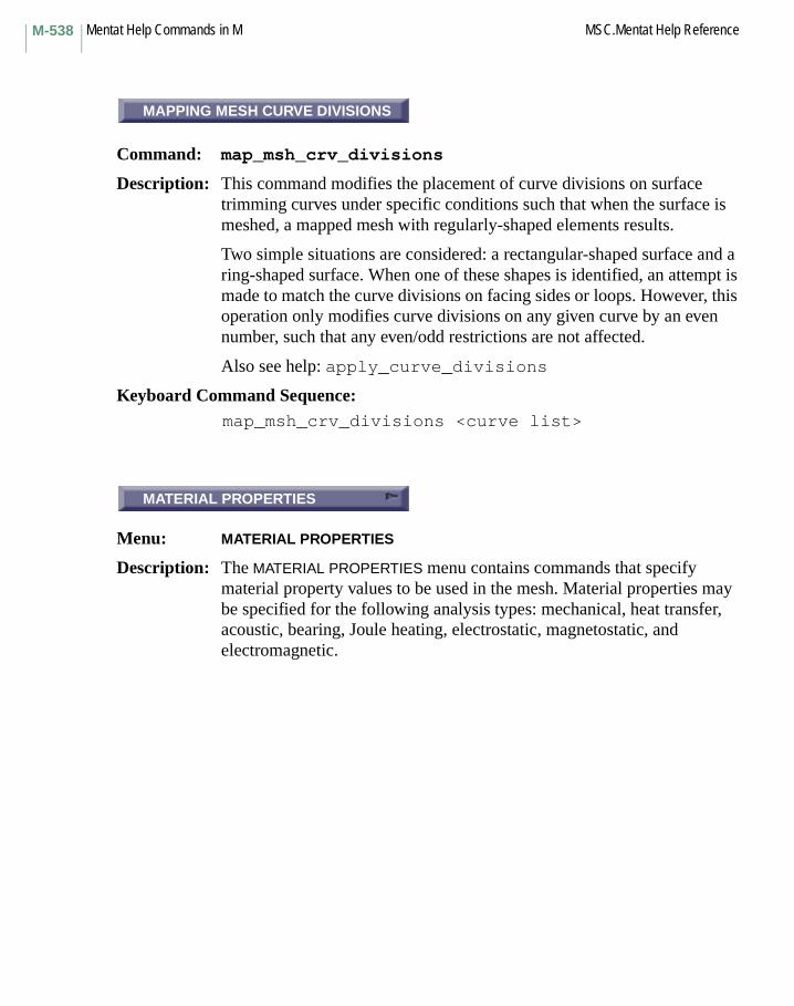
Mentat Help Commands in M MSC.Mentat Help ReferenceM-538
MAPPING MESH CURVE DIVISIONS
Command: map_msh_crv_divisions
Description: This command modifies the placement of curve divisions on surface trimming curves under specific conditions such that when the surface is meshed, a mapped mesh with regularly-shaped elements results.
Two simple situations are considered: a rectangular-shaped surface and a ring-shaped surface. When one of these shapes is identified, an attempt is made to match the curve divisions on facing sides or loops. However, this operation only modifies curve divisions on any given curve by an even number, such that any even/odd restrictions are not affected.
Also see help: apply_curve_divisions
Keyboard Command Sequence:map_msh_crv_divisions <curve list>
MATERIAL PROPERTIES
Menu: MATERIAL PROPERTIES
Description: The MATERIAL PROPERTIES menu contains commands that specify material property values to be used in the mesh. Material properties may be specified for the following analysis types: mechanical, heat transfer, acoustic, bearing, Joule heating, electrostatic, magnetostatic, and electromagnetic.
MAPPING MESH CURVE DIVISIONS
MATERIAL PROPERTIES

M-539MSC.Mentat Help Reference Mentat Help Commands in M
MATCH CURVE DIVISIONS
Command: match_curves
Description: This command assures that the number of mesh divisions on coincident curves are equal and the divisions are aligned. Tolerance is used to determine when two curves are actually coincident. The tolerance is computed by multiplying the relative tolerance value by the curve length.
Keyboard Command Sequence:match_curves <curve_list>
MATCH CURVE DIVISIONS
Command: match_curves_af
Description: This command assures that the number of mesh divisions on coincident curves are equal and the divisions are aligned. The given tolerance is used to determine when two curves are actually coincident.
Keyboard Command Sequence:match_curves_af <tolerance> <curve_list>
MATCH CURVE DIVISIONS
MATCH CURVE DIVISIONS
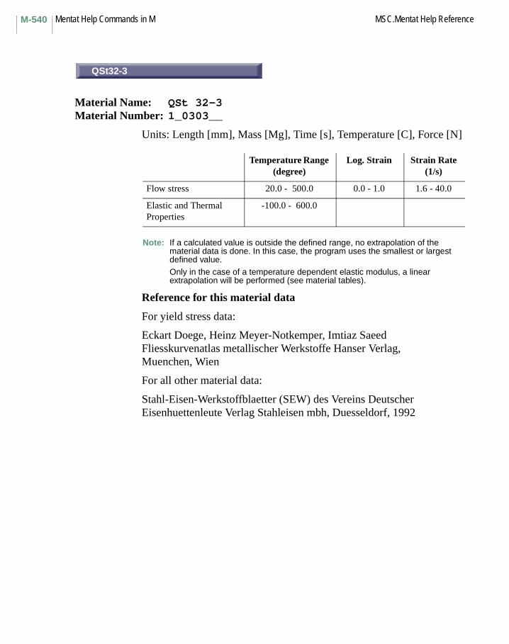
Mentat Help Commands in M MSC.Mentat Help ReferenceM-540
QSt32-3
Material Name: QSt 32-3Material Number: 1_0303__
Units: Length [mm], Mass [Mg], Time [s], Temperature [C], Force [N]
Note: If a calculated value is outside the defined range, no extrapolation of the material data is done. In this case, the program uses the smallest or largest defined value.
Only in the case of a temperature dependent elastic modulus, a linear extrapolation will be performed (see material tables).
Reference for this material data
For yield stress data:
Eckart Doege, Heinz Meyer-Notkemper, Imtiaz SaeedFliesskurvenatlas metallischer Werkstoffe Hanser Verlag,Muenchen, Wien
For all other material data:
Stahl-Eisen-Werkstoffblaetter (SEW) des Vereins Deutscher Eisenhuettenleute Verlag Stahleisen mbh, Duesseldorf, 1992
Temperature Range (degree)
Log. Strain Strain Rate (1/s)
Flow stress 20.0 - 500.0 0.0 - 1.0 1.6 - 40.0
Elastic and Thermal Properties
-100.0 - 600.0
QSt32-3
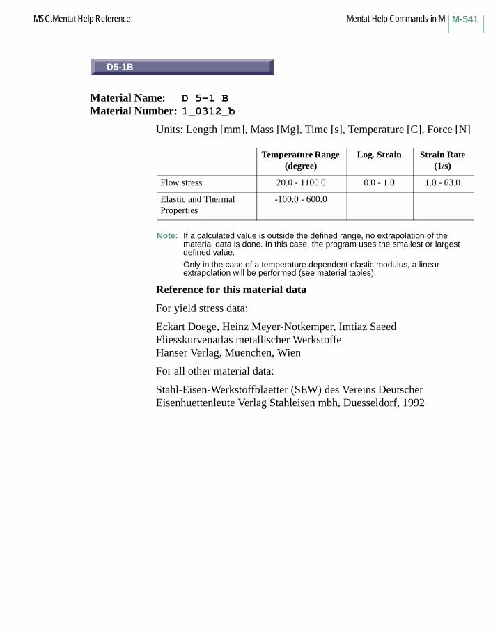
M-541MSC.Mentat Help Reference Mentat Help Commands in M
D5-1B
Material Name: D 5-1 BMaterial Number: 1_0312_b
Units: Length [mm], Mass [Mg], Time [s], Temperature [C], Force [N]
Note: If a calculated value is outside the defined range, no extrapolation of the material data is done. In this case, the program uses the smallest or largest defined value.
Only in the case of a temperature dependent elastic modulus, a linear extrapolation will be performed (see material tables).
Reference for this material data
For yield stress data:
Eckart Doege, Heinz Meyer-Notkemper, Imtiaz SaeedFliesskurvenatlas metallischer WerkstoffeHanser Verlag, Muenchen, Wien
For all other material data:
Stahl-Eisen-Werkstoffblaetter (SEW) des Vereins Deutscher Eisenhuettenleute Verlag Stahleisen mbh, Duesseldorf, 1992
Temperature Range (degree)
Log. Strain Strain Rate (1/s)
Flow stress 20.0 - 1100.0 0.0 - 1.0 1.0 - 63.0
Elastic and Thermal Properties
-100.0 - 600.0
D5-1B

Mentat Help Commands in M MSC.Mentat Help ReferenceM-542
D5-1U
Material Name: D 5-1 UMaterial Number: 1_0312_u
Units: Length [mm], Mass [Mg], Time [s], Temperature [C], Force [N]
Note: If a calculated value is outside the defined range, no extrapolation of the material data is done. In this case, the program uses the smallest or largest defined value.
Only in the case of a temperature dependent elastic modulus, a linear extrapolation will be performed (see material tables).
Reference for this material data
For yield stress data:
Eckart Doege, Heinz Meyer-Notkemper,Imtiaz Saeed Fliesskurvenatlas metallischer Werkstoffe Hanser Verlag,Muenchen, Wien
For all other material data:
Stahl-Eisen-Werkstoffblaetter (SEW) des Vereins Deutscher Eisenhuettenleute Verlag Stahleisen mbh, Duesseldorf, 1992
Temperature Range (degree)
Log. Strain Strain Rate (1/s)
Flow stress 20.0 - 1100.0 0.0 - 1.0 1.0 - 63.0
Elastic and Thermal Properties
-100.0 - 600.0
D5-1U
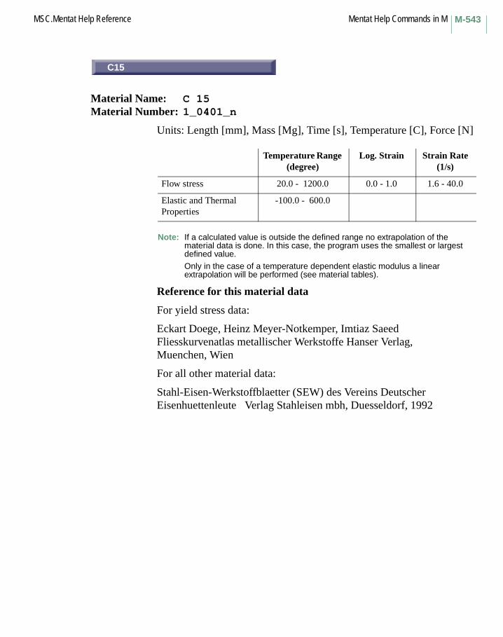
M-543MSC.Mentat Help Reference Mentat Help Commands in M
C15
Material Name: C 15Material Number: 1_0401_n
Units: Length [mm], Mass [Mg], Time [s], Temperature [C], Force [N]
Note: If a calculated value is outside the defined range no extrapolation of the material data is done. In this case, the program uses the smallest or largest defined value.
Only in the case of a temperature dependent elastic modulus a linear extrapolation will be performed (see material tables).
Reference for this material data
For yield stress data:
Eckart Doege, Heinz Meyer-Notkemper, Imtiaz SaeedFliesskurvenatlas metallischer Werkstoffe Hanser Verlag,Muenchen, Wien
For all other material data:
Stahl-Eisen-Werkstoffblaetter (SEW) des Vereins Deutscher Eisenhuettenleute Verlag Stahleisen mbh, Duesseldorf, 1992
Temperature Range (degree)
Log. Strain Strain Rate (1/s)
Flow stress 20.0 - 1200.0 0.0 - 1.0 1.6 - 40.0
Elastic and Thermal Properties
-100.0 - 600.0
C15

Mentat Help Commands in M MSC.Mentat Help ReferenceM-544
C15 (w)
Material Name: C 15Material Number: 1_0401_w
Units: Length [mm], Mass [Mg], Time [s], Temperature [C], Force [N]
Note: If a calculated value is outside the defined range, no extrapolation of the material data is done. In this case, the program uses the smallest or largest defined value.
Only in the case of a temperature dependent elastic modulus, a linear extrapolation will be performed (see material tables).
Reference for this material data
For yield stress data:
Eckart Doege, Heinz Meyer-Notkemper, Imtiaz SaeedFliesskurvenatlas metallischer Werkstoffe Hanser Verlag,Muenchen, Wien
For all other material data:
Stahl-Eisen-Werkstoffblaetter (SEW) des Vereins Deutscher Eisenhuettenleute Verlag Stahleisen mbh, Duesseldorf, 1992
Temperature Range (degree)
Log. Strain Strain Rate (1/s)
Flow stress 20.0 - 1000.0 0.0 - 1.0 8.0 - 8.0
Elastic and Thermal Properties
-100.0 - 600.0
C15 (w)

M-545MSC.Mentat Help Reference Mentat Help Commands in M
C22
Material Name: C 22Material Number: 1_0402__
Units: Length [mm], Mass [Mg], Time [s], Temperature [C], Force [N]
Note: If a calculated value is outside the defined range no extrapolation of the material data is done. In this case, the program uses the smallest or largest defined value.
Only in the case of a temperature dependent elastic modulus a linear extrapolation will be performed (see material tables).
Reference for this material data
For yield stress data:
Eckart Doege, Heinz Meyer-Notkemper, Imtiaz SaeedFliesskurvenatlas metallischer Werkstoffe Hanser Verlag,Muenchen, Wien
For all other material data:
Stahl-Eisen-Werkstoffblaetter (SEW) des Vereins Deutscher Eisenhuettenleute Verlag Stahleisen mbh, Duesseldorf, 1992
Temperature Range (degree)
Log. Strain Strain Rate (1/s)
Flow stress 600.0 - 1100.0 0.0 - 1.0 0.2 - 63.0
Elastic and Thermal Properties
-100.0 - 600.0
C22

Mentat Help Commands in M MSC.Mentat Help ReferenceM-546
C35
Material Name: C 35Material Number: 1_0501_a
Units: Length [mm], Mass [Mg], Time [s], Temperature [C], Force [N]
Note: If a calculated value is outside the defined range, no extrapolation of the material data is done. In this case, the program uses the smallest or largest defined value.
Only in the case of a temperature dependent elastic modulus, a linear extrapolation will be performed (see material tables).
Reference for this material data
For yield stress data:
Eckart Doege, Heinz Meyer-Notkemper, Imtiaz SaeedFliesskurvenatlas metallischer Werkstoffe Hanser Verlag,Muenchen, Wien
For all other material data:
Stahl-Eisen-Werkstoffblaetter (SEW) des Vereins Deutscher Eisenhuettenleute Verlag Stahleisen mbh, Duesseldorf, 1992
Temperature Range (degree)
Log. Strain Strain Rate (1/s)
Flow stress 20.0 - 1100.0 0.0 - 1.0 1.0 - 100.0
Elastic and Thermal Properties
-100.0 - 600.0
C35

M-547MSC.Mentat Help Reference Mentat Help Commands in M
C35 (n)
Material Name: C 35Material Number: 1_0501_n
Units: Length [mm], Mass [Mg], Time [s], Temperature [C], Force [N]
Note: If a calculated value is outside the defined range, no extrapolation of the material data is done. In this case, the program uses the smallest or largest defined value.
Only in the case of a temperature dependent elastic modulus, a linear extrapolation will be performed (see material tables).
Reference for this material data
For yield stress data:
Eckart Doege, Heinz Meyer-Notkemper, Imtiaz SaeedFliesskurvenatlas metallischer Werkstoffe Hanser Verlag,Muenchen, Wien
For all other material data:
Stahl-Eisen-Werkstoffblaetter (SEW) des Vereins Deutscher Eisenhuettenleute Verlag Stahleisen mbh, Duesseldorf, 1992
Temperature Range (degree)
Log. Strain Strain Rate (1/s)
Flow stress 700.0 - 1100.0 0.0 - 1.0 1.6 - 40.0
Elastic and Thermal Properties
-100.0 - 600.0
C35 (n)
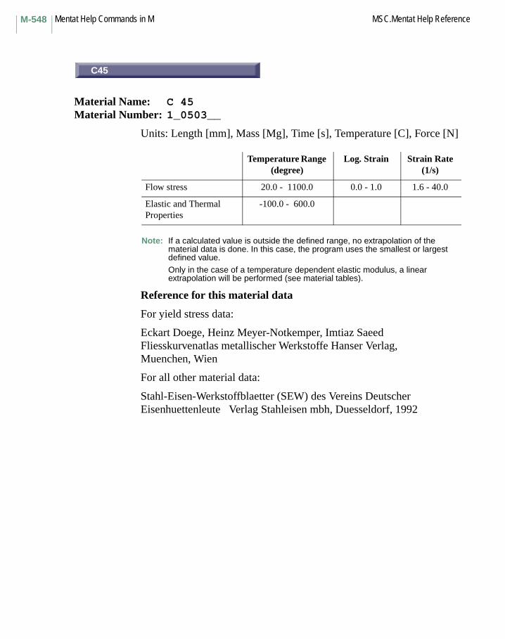
Mentat Help Commands in M MSC.Mentat Help ReferenceM-548
C45
Material Name: C 45Material Number: 1_0503__
Units: Length [mm], Mass [Mg], Time [s], Temperature [C], Force [N]
Note: If a calculated value is outside the defined range, no extrapolation of the material data is done. In this case, the program uses the smallest or largest defined value.
Only in the case of a temperature dependent elastic modulus, a linear extrapolation will be performed (see material tables).
Reference for this material data
For yield stress data:
Eckart Doege, Heinz Meyer-Notkemper, Imtiaz SaeedFliesskurvenatlas metallischer Werkstoffe Hanser Verlag,Muenchen, Wien
For all other material data:
Stahl-Eisen-Werkstoffblaetter (SEW) des Vereins Deutscher Eisenhuettenleute Verlag Stahleisen mbh, Duesseldorf, 1992
Temperature Range (degree)
Log. Strain Strain Rate (1/s)
Flow stress 20.0 - 1100.0 0.0 - 1.0 1.6 - 40.0
Elastic and Thermal Properties
-100.0 - 600.0
C45
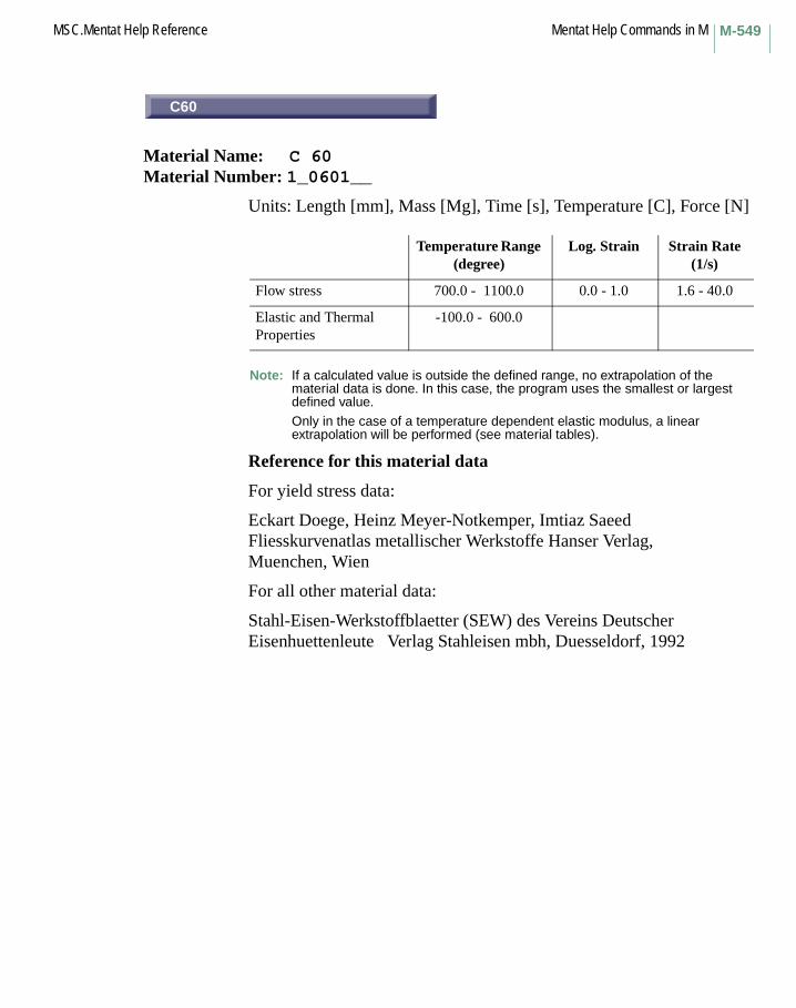
M-549MSC.Mentat Help Reference Mentat Help Commands in M
C60
Material Name: C 60Material Number: 1_0601__
Units: Length [mm], Mass [Mg], Time [s], Temperature [C], Force [N]
Note: If a calculated value is outside the defined range, no extrapolation of the material data is done. In this case, the program uses the smallest or largest defined value.
Only in the case of a temperature dependent elastic modulus, a linear extrapolation will be performed (see material tables).
Reference for this material data
For yield stress data:
Eckart Doege, Heinz Meyer-Notkemper, Imtiaz SaeedFliesskurvenatlas metallischer Werkstoffe Hanser Verlag,Muenchen, Wien
For all other material data:
Stahl-Eisen-Werkstoffblaetter (SEW) des Vereins Deutscher Eisenhuettenleute Verlag Stahleisen mbh, Duesseldorf, 1992
Temperature Range (degree)
Log. Strain Strain Rate (1/s)
Flow stress 700.0 - 1100.0 0.0 - 1.0 1.6 - 40.0
Elastic and Thermal Properties
-100.0 - 600.0
C60

Mentat Help Commands in M MSC.Mentat Help ReferenceM-550
Ck15
Material Name: Ck 15Material Number: 1_1141__
Units: Length [mm], Mass [Mg], Time [s], Temperature [C], Force [N]
Note: If a calculated value is outside the defined range, no extrapolation of the material data is done. In this case, the program uses the smallest or largest defined value.
Only in the case of a temperature dependent elastic modulus, a linear extrapolation will be performed (see material tables).
Reference for this material data
For yield stress data:
Eckart Doege, Heinz Meyer-Notkemper, Imtiaz SaeedFliesskurvenatlas metallischer Werkstoffe Hanser Verlag,Muenchen, Wien
For all other material data:
Stahl-Eisen-Werkstoffblaetter (SEW) des Vereins Deutscher Eisenhuettenleute Verlag Stahleisen mbh, Duesseldorf, 1992
Temperature Range (degree)
Log. Strain Strain Rate (1/s)
Flow stress 800.0 - 1200.0 0.0 - 1.0 1.6 - 40.0
Elastic and Thermal Properties
-100.0 - 600.0
Ck15

M-551MSC.Mentat Help Reference Mentat Help Commands in M
Ck15 (h)
Material Name: Ck 15Material Number: 1_1141_h
Units: Length [mm], Mass [Mg], Time [s], Temperature [C], Force [N]
Note: If a calculated value is outside the defined range, no extrapolation of the material data is done. In this case, the program uses the smallest or largest defined value.
Only in the case of a temperature dependent elastic modulus, a linear extrapolation will be performed (see material tables).
Reference for this material data
For yield stress data:
Eckart Doege, Heinz Meyer-Notkemper, Imtiaz SaeedFliesskurvenatlas metallischer Werkstoffe Hanser Verlag,Muenchen, Wien
For all other material data:
Stahl-Eisen-Werkstoffblaetter (SEW) des Vereins Deutscher Eisenhuettenleute Verlag Stahleisen mbh, Duesseldorf, 1992
Temperature Range (degree)
Log. Strain Strain Rate (1/s)
Flow stress 20.0 - 600.0 0.0 - 1.0 1.6 - 40.0
Elastic and Thermal Properties
-100.0 - 600.0
Ck15 (h)

Mentat Help Commands in M MSC.Mentat Help ReferenceM-552
Ck15 (n)
Material Name: Ck 15Material Number: 1_1141_n
Units: Length [mm], Mass [Mg], Time [s], Temperature [C], Force [N]
Note: If a calculated value is outside the defined range, no extrapolation of the material data is done. In this case, the program uses the smallest or largest defined value.
Only in the case of a temperature dependent elastic modulus, a linear extrapolation will be performed (see material tables).
Reference for this material data
For yield stress data:
Eckart Doege, Heinz Meyer-Notkemper, Imtiaz SaeedFliesskurvenatlas metallischer Werkstoffe Hanser Verlag,Muenchen, Wien
For all other material data:
Stahl-Eisen-Werkstoffblaetter (SEW) des Vereins Deutscher Eisenhuettenleute Verlag Stahleisen mbh, Duesseldorf, 1992
Temperature Range (degree)
Log. Strain Strain Rate (1/s)
Flow stress 20.0 - 600.0 0.0 - 1.0 1.6 - 40.0
Elastic and Thermal Properties
-100.0 - 600.0
Ck15 (n)

M-553MSC.Mentat Help Reference Mentat Help Commands in M
Ck15 (w)
Material Name: Ck 15Material Number: 1_1141_w
Units: Length [mm], Mass [Mg], Time [s], Temperature [C], Force [N]
Note: If a calculated value is outside the defined range, no extrapolation of the material data is done. In this case, the program uses the smallest or largest defined value.
Only in the case of a temperature dependent elastic modulus, a linear extrapolation will be performed (see material tables).
Reference for this material data
For yield stress data:
Eckart Doege, Heinz Meyer-Notkemper, Imtiaz SaeedFliesskurvenatlas metallischer Werkstoffe Hanser Verlag,Muenchen, Wien
For all other material data:
Stahl-Eisen-Werkstoffblaetter (SEW) des Vereins Deutscher Eisenhuettenleute Verlag Stahleisen mbh, Duesseldorf, 1992
Temperature Range (degree)
Log. Strain Strain Rate (1/s)
Flow stress 20.0 - 600.0 0.0 - 1.0 1.6 - 40.0
Elastic and Thermal Properties
-100.0 - 600.0
Ck15 (w)

Mentat Help Commands in M MSC.Mentat Help ReferenceM-554
Ck35
Material Name: Ck 35Material Number: 1_1181__
Units: Length [mm], Mass [Mg], Time [s], Temperature [C], Force [N]
Note: If a calculated value is outside the defined range, no extrapolation of the material data is done. In this case, the program uses the smallest or largest defined value.
Only in the case of a temperature dependent elastic modulus, a linear extrapolation will be performed (see material tables).
Reference for this material data
For yield stress data:
Eckart Doege, Heinz Meyer-Notkemper, Imtiaz SaeedFliesskurvenatlas metallischer Werkstoffe Hanser Verlag,Muenchen, Wien
For all other material data:
Stahl-Eisen-Werkstoffblaetter (SEW) des Vereins Deutscher Eisenhuettenleute Verlag Stahleisen mbh, Duesseldorf, 1992
Temperature Range (degree)
Log. Strain Strain Rate (1/s)
Flow stress 1080.0 - 1330.0 0.0 - 2.0 0.1 - 36.0
Elastic and Thermal Properties
-100.0 - 600.0
Ck35

M-555MSC.Mentat Help Reference Mentat Help Commands in M
Ck45
Material Name: Ck 45Material Number: 1_1191__
Units: Length [mm], Mass [Mg], Time [s], Temperature [C], Force [N]
Note: If a calculated value is outside the defined range, no extrapolation of the material data is done. In this case, the program uses the smallest or largest defined value.
Only in the case of a temperature dependent elastic modulus, a linear extrapolation will be performed (see material tables).
Reference for this material data
For yield stress data:
Eckart Doege, Heinz Meyer-Notkemper, Imtiaz SaeedFliesskurvenatlas metallischer Werkstoffe Hanser Verlag,Muenchen, Wien
For all other material data:
Stahl-Eisen-Werkstoffblaetter (SEW) des Vereins Deutscher Eisenhuettenleute Verlag Stahleisen mbh, Duesseldorf, 1992
Temperature Range (degree)
Log. Strain Strain Rate (1/s)
Flow stress 800.0 - 1200.0 0.0 - 1.0 1.6 - 40.0
Elastic and Thermal Properties
-100.0 - 600.0
Ck45

Mentat Help Commands in M MSC.Mentat Help ReferenceM-556
Ck45 (h)
Material Name: Ck 45Material Number: 1_1191_h
Units: Length [mm], Mass [Mg], Time [s], Temperature [C], Force [N]
Note: If a calculated value is outside the defined range, no extrapolation of the material data is done. In this case, the program uses the smallest or largest defined value.
Only in the case of a temperature dependent elastic modulus, a linear extrapolation will be performed (see material tables).
Reference for this material data
For yield stress data:
Eckart Doege, Heinz Meyer-Notkemper, Imtiaz SaeedFliesskurvenatlas metallischer Werkstoffe Hanser Verlag,Muenchen, Wien
For all other material data:
Stahl-Eisen-Werkstoffblaetter (SEW) des Vereins Deutscher Eisenhuettenleute Verlag Stahleisen mbh, Duesseldorf, 1992
Temperature Range (degree)
Log. Strain Strain Rate (1/s)
Flow stress 20.0 - 600.0 0.0 - 1.0 1.6 - 40.0
Elastic and Thermal Properties
-100.0 - 600.0
Ck45 (h)

M-557MSC.Mentat Help Reference Mentat Help Commands in M
Ck45 (w)
Material Name: Ck 45Material Number: 1_1191_w
Units: Length [mm], Mass [Mg], Time [s], Temperature [C], Force [N]
Note: If a calculated value is outside the defined range, no extrapolation of the material data is done. In this case, the program uses the smallest or largest defined value.
Only in the case of a temperature dependent elastic modulus, a linear extrapolation will be performed (see material tables).
Reference for this material data
For yield stress data:
Eckart Doege, Heinz Meyer-Notkemper, Imtiaz SaeedFliesskurvenatlas metallischer Werkstoffe Hanser Verlag,Muenchen, Wien
For all other material data:
Stahl-Eisen-Werkstoffblaetter (SEW) des Vereins Deutscher Eisenhuettenleute Verlag Stahleisen mbh, Duesseldorf, 1992
Temperature Range (degree)
Log. Strain Strain Rate (1/s)
Flow stress 20.0 - 600.0 0.0 - 1.0 1.6 - 40.0
Elastic and Thermal Properties
-100.0 - 600.0
Ck45 (w)

Mentat Help Commands in M MSC.Mentat Help ReferenceM-558
Cf53
Material Name: Cf 53Material Number: 1_1213__
Units: Length [mm], Mass [Mg], Time [s], Temperature [C], Force [N]
Note: If a calculated value is outside the defined range, no extrapolation of the material data is done. In this case, the program uses the smallest or largest defined value.
Only in the case of a temperature dependent elastic modulus, a linear extrapolation will be performed (see material tables).
Reference for this material data
For yield stress data:
Eckart Doege, Heinz Meyer-Notkemper, Imtiaz SaeedFliesskurvenatlas metallischer Werkstoffe Hanser Verlag,Muenchen, Wien
For all other material data:
Stahl-Eisen-Werkstoffblaetter (SEW) des Vereins Deutscher Eisenhuettenleute Verlag Stahleisen mbh, Duesseldorf, 1992
Temperature Range (degree)
Log. Strain Strain Rate (1/s)
Flow stress 20.0 - 800.0 0.0 - 1.0 40.0 - 40.0
Elastic and Thermal Properties
-100.0 - 600.0
Cf53

M-559MSC.Mentat Help Reference Mentat Help Commands in M
Ck67
Material Name: Ck 67Material Number: 1_1231__
Units: Length [mm], Mass [Mg], Time [s], Temperature [C], Force [N]
Note: If a calculated value is outside the defined range, no extrapolation of the material data is done. In this case, the program uses the smallest or largest defined value.
Only in the case of a temperature dependent elastic modulus, a linear extrapolation will be performed (see material tables).
Reference for this material data
For yield stress data:
Eckart Doege, Heinz Meyer-Notkemper, Imtiaz SaeedFliesskurvenatlas metallischer Werkstoffe Hanser Verlag,Muenchen, Wien
For all other material data:
Stahl-Eisen-Werkstoffblaetter (SEW) des Vereins Deutscher Eisenhuettenleute Verlag Stahleisen mbh, Duesseldorf, 1992
Temperature Range (degree)
Log. Strain Strain Rate (1/s)
Flow stress 20.0 - 1000.0 0.0 - 1.0 1.0 - 63.0
Elastic and Thermal Properties
-100.0 - 600.0
Ck67
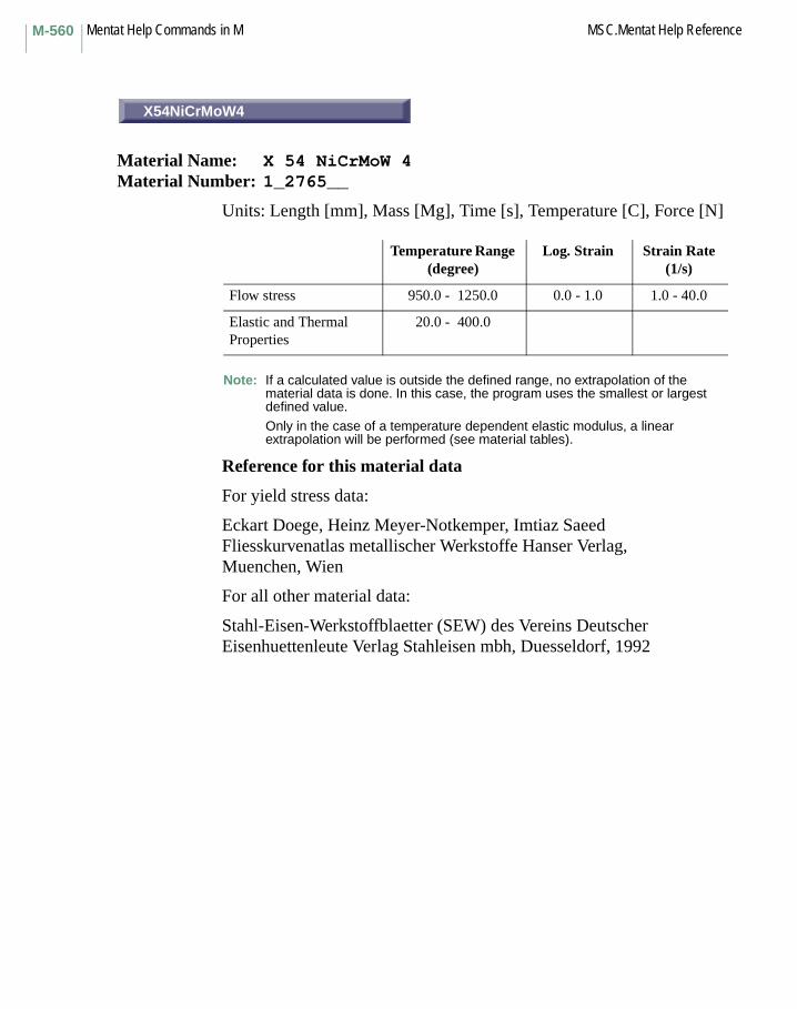
Mentat Help Commands in M MSC.Mentat Help ReferenceM-560
X54NiCrMoW4
Material Name: X 54 NiCrMoW 4Material Number: 1_2765__
Units: Length [mm], Mass [Mg], Time [s], Temperature [C], Force [N]
Note: If a calculated value is outside the defined range, no extrapolation of the material data is done. In this case, the program uses the smallest or largest defined value.
Only in the case of a temperature dependent elastic modulus, a linear extrapolation will be performed (see material tables).
Reference for this material data
For yield stress data:
Eckart Doege, Heinz Meyer-Notkemper, Imtiaz SaeedFliesskurvenatlas metallischer Werkstoffe Hanser Verlag,Muenchen, Wien
For all other material data:
Stahl-Eisen-Werkstoffblaetter (SEW) des Vereins Deutscher Eisenhuettenleute Verlag Stahleisen mbh, Duesseldorf, 1992
Temperature Range (degree)
Log. Strain Strain Rate (1/s)
Flow stress 950.0 - 1250.0 0.0 - 1.0 1.0 - 40.0
Elastic and Thermal Properties
20.0 - 400.0
X54NiCrMoW4

M-561MSC.Mentat Help Reference Mentat Help Commands in M
100Cr6
Material Name: 100 Cr 6 Material Number: 1_3505__
Units: Length [mm], Mass [Mg], Time [s], Temperature [C], Force [N]
Note: If a calculated value is outside the defined range, no extrapolation of the material data is done. In this case, the program uses the smallest or largest defined value.
Only in the case of a temperature dependent elastic modulus, a linear extrapolation will be performed (see material tables).
Reference for this material data
For yield stress data:
Eckart Doege, Heinz Meyer-Notkemper, Imtiaz SaeedFliesskurvenatlas metallischer Werkstoffe Hanser Verlag,Muenchen, Wien
For all other material data:
Stahl-Eisen-Werkstoffblaetter (SEW) des Vereins Deutscher Eisenhuettenleute Verlag Stahleisen mbh, Duesseldorf, 1992
Temperature Range (degree)
Log. Strain Strain Rate (1/s)
Flow stress 20.0 - 1200.0 0.0 - 1.0 1.6 - 40.0
Elastic and Thermal Properties
-100.0 - 600.0
100Cr6

Mentat Help Commands in M MSC.Mentat Help ReferenceM-562
X10Cr13
Material Name: X 10 Cr 13Material Number: 1_4006__
Units: Length [mm], Mass [Mg], Time [s], Temperature [C], Force [N]
Note: If a calculated value is outside the defined range, no extrapolation of the material data is done. In this case, the program uses the smallest or largest defined value.
Only in the case of a temperature dependent elastic modulus, a linear extrapolation will be performed (see material tables).
Reference for this material data
For yield stress data:
Eckart Doege, Heinz Meyer-Notkemper, Imtiaz SaeedFliesskurvenatlas metallischer Werkstoffe Hanser Verlag,Muenchen, Wien
For all other material data:
Stahl-Eisen-Werkstoffblaetter (SEW) des Vereins Deutscher Eisenhuettenleute Verlag Stahleisen mbh, Duesseldorf, 1992
Temperature Range (degree)
Log. Strain Strain Rate (1/s)
Flow stress 20.0 - 1100.0 0.0 - 1.0 1.0 - 90.0
Elastic and Thermal Properties
20.0 - 600.0
X10Cr13
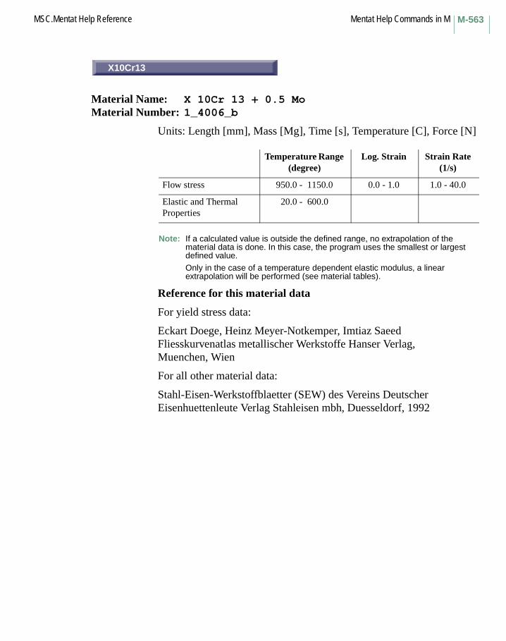
M-563MSC.Mentat Help Reference Mentat Help Commands in M
X10Cr13
Material Name: X 10Cr 13 + 0.5 MoMaterial Number: 1_4006_b
Units: Length [mm], Mass [Mg], Time [s], Temperature [C], Force [N]
Note: If a calculated value is outside the defined range, no extrapolation of the material data is done. In this case, the program uses the smallest or largest defined value.
Only in the case of a temperature dependent elastic modulus, a linear extrapolation will be performed (see material tables).
Reference for this material data
For yield stress data:
Eckart Doege, Heinz Meyer-Notkemper, Imtiaz SaeedFliesskurvenatlas metallischer Werkstoffe Hanser Verlag,Muenchen, Wien
For all other material data:
Stahl-Eisen-Werkstoffblaetter (SEW) des Vereins Deutscher Eisenhuettenleute Verlag Stahleisen mbh, Duesseldorf, 1992
Temperature Range (degree)
Log. Strain Strain Rate (1/s)
Flow stress 950.0 - 1150.0 0.0 - 1.0 1.0 - 40.0
Elastic and Thermal Properties
20.0 - 600.0
X10Cr13

Mentat Help Commands in M MSC.Mentat Help ReferenceM-564
X20Cr13
Material Name: X 20 Cr 13Material Number: 1_4021__
Units: Length [mm], Mass [Mg], Time [s], Temperature [C], Force [N]
Note: If a calculated value is outside the defined range, no extrapolation of the material data is done. In this case, the program uses the smallest or largest defined value.
Only in the case of a temperature dependent elastic modulus, a linear extrapolation will be performed (see material tables).
Reference for this material data
For yield stress data:
Eckart Doege, Heinz Meyer-Notkemper, Imtiaz SaeedFliesskurvenatlas metallischer Werkstoffe Hanser Verlag,Muenchen, Wien
For all other material data:
Stahl-Eisen-Werkstoffblaetter (SEW) des Vereins Deutscher Eisenhuettenleute Verlag Stahleisen mbh, Duesseldorf, 1992
Temperature Range (degree)
Log. Strain Strain Rate (1/s)
Flow stress 20.0 - 1100.0 0.0 - 1.0 1.6 - 40.0
Elastic and Thermal Properties
20.0 - 600.0
X20Cr13

M-565MSC.Mentat Help Reference Mentat Help Commands in M
X40Cr13
Material Name: X 40 Cr 13Material Number: 1_4034__
Units: Length [mm], Mass [Mg], Time [s], Temperature [C], Force [N]
Note: If a calculated value is outside the defined range, no extrapolation of the material data is done. In this case, the program uses the smallest or largest defined value.
Only in the case of a temperature dependent elastic modulus, a linear extrapolation will be performed (see material tables).
Reference for this material data
For yield stress data:
Eckart Doege, Heinz Meyer-Notkemper, Imtiaz SaeedFliesskurvenatlas metallischer Werkstoffe Hanser Verlag,Muenchen, Wien
For all other material data:
Stahl-Eisen-Werkstoffblaetter (SEW) des Vereins Deutscher Eisenhuettenleute Verlag Stahleisen mbh, Duesseldorf, 1992
Temperature Range (degree)
Log. Strain Strain Rate (1/s)
Flow stress 20.0 - 1100.0 0.0 - 1.0 1.6 - 40.0
Elastic and Thermal Properties
20.0 - 600.0
X40Cr13

Mentat Help Commands in M MSC.Mentat Help ReferenceM-566
X22CrNi17
Material Name: X 22 CrNi 17Material Number: 1_4057__
Units: Length [mm], Mass [Mg], Time [s], Temperature [C], Force [N]
Note: If a calculated value is outside the defined range, no extrapolationof the material data is done. In this case, the program uses the smallest or largest defined value.
Only in the case of a temperature dependent elastic modulus, a linear extrapolation will be performed (see material tables).
Reference for this material data
For yield stress data:
Eckart Doege, Heinz Meyer-Notkemper, Imtiaz SaeedFliesskurvenatlas metallischer Werkstoffe Hanser Verlag,Muenchen, Wien
For all other material data:
Stahl-Eisen-Werkstoffblaetter (SEW) des Vereins Deutscher Eisenhuettenleute Verlag Stahleisen mbh, Duesseldorf, 1992
Temperature Range (degree)
Log. Strain Strain Rate (1/s)
Flow stress 950.0 - 1250.0 0.0 - 1.0 1.0 - 40.0
Elastic and Thermal Properties
-100.0 - 800.0
X22CrNi17
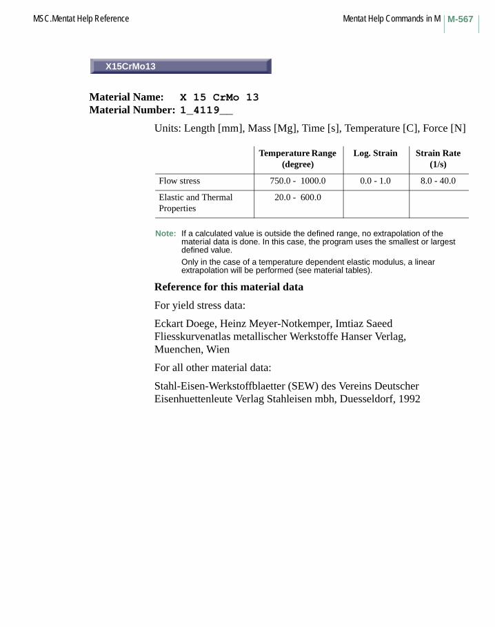
M-567MSC.Mentat Help Reference Mentat Help Commands in M
X15CrMo13
Material Name: X 15 CrMo 13Material Number: 1_4119__
Units: Length [mm], Mass [Mg], Time [s], Temperature [C], Force [N]
Note: If a calculated value is outside the defined range, no extrapolation of the material data is done. In this case, the program uses the smallest or largest defined value.
Only in the case of a temperature dependent elastic modulus, a linear extrapolation will be performed (see material tables).
Reference for this material data
For yield stress data:
Eckart Doege, Heinz Meyer-Notkemper, Imtiaz SaeedFliesskurvenatlas metallischer Werkstoffe Hanser Verlag,Muenchen, Wien
For all other material data:
Stahl-Eisen-Werkstoffblaetter (SEW) des Vereins Deutscher Eisenhuettenleute Verlag Stahleisen mbh, Duesseldorf, 1992
Temperature Range (degree)
Log. Strain Strain Rate (1/s)
Flow stress 750.0 - 1000.0 0.0 - 1.0 8.0 - 40.0
Elastic and Thermal Properties
20.0 - 600.0
X15CrMo13
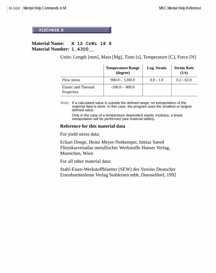
Mentat Help Commands in M MSC.Mentat Help ReferenceM-568
X12CrNi18_8
Material Name: X 12 CrNi 18 8Material Number: 1_4300__
Units: Length [mm], Mass [Mg], Time [s], Temperature [C], Force [N]
Note: If a calculated value is outside the defined range, no extrapolation of the material data is done. In this case, the program uses the smallest or largest defined value.
Only in the case of a temperature dependent elastic modulus, a linear extrapolation will be performed (see material tables).
Reference for this material data
For yield stress data:
Eckart Doege, Heinz Meyer-Notkemper, Imtiaz SaeedFliesskurvenatlas metallischer Werkstoffe Hanser Verlag,Muenchen, Wien
For all other material data:
Stahl-Eisen-Werkstoffblaetter (SEW) des Vereins Deutscher Eisenhuettenleute Verlag Stahleisen mbh, Duesseldorf, 1992
Temperature Range (degree)
Log. Strain Strain Rate (1/s)
Flow stress 900.0 - 1200.0 0.0 - 1.0 0.2 - 63.0
Elastic and Thermal Properties
-100.0 - 800.0
X12CrNi18_8

M-569MSC.Mentat Help Reference Mentat Help Commands in M
X5CrNi18_9
Material Name: X 5 CrNi 18 9Material Number: 1_4301__
Units: Length [mm], Mass [Mg], Time [s], Temperature [C], Force [N]
Note: If a calculated value is outside the defined range, no extrapolation of the material data is done. In this case, the program uses the smallest or largest defined value.
Only in the case of a temperature dependent elastic modulus, a linear extrapolation will be performed (see material tables).
Reference for this material data
For yield stress data:
Eckart Doege, Heinz Meyer-Notkemper, Imtiaz SaeedFliesskurvenatlas metallischer Werkstoffe Hanser Verlag,Muenchen, Wien
For all other material data:
Stahl-Eisen-Werkstoffblaetter (SEW) des Vereins Deutscher Eisenhuettenleute Verlag Stahleisen mbh, Duesseldorf, 1992
Temperature Range (degree)
Log. Strain Strain Rate (1/s)
Flow stress 20.0 - 1100.0 0.0 - 1.0 0.2 - 63.0
Elastic and Thermal Properties
-100.0 - 800.0
X5CrNi18_9

Mentat Help Commands in M MSC.Mentat Help ReferenceM-570
X8CrNi12_12
Material Name: X 8 CrNi 12 12Material Number: 1_4307__
Units: Length [mm], Mass [Mg], Time [s], Temperature [C], Force [N]
Note: If a calculated value is outside the defined range, no extrapolation of the material data is done. In this case, the program uses the smallest or largest defined value.
Only in the case of a temperature dependent elastic modulus, a linear extrapolation will be performed (see material tables).
Reference for this material data
For yield stress data:
Eckart Doege, Heinz Meyer-Notkemper, Imtiaz SaeedFliesskurvenatlas metallischer Werkstoffe Hanser Verlag,Muenchen, Wien
For all other material data:
Stahl-Eisen-Werkstoffblaetter (SEW) des Vereins Deutscher Eisenhuettenleute Verlag Stahleisen mbh, Duesseldorf, 1992
Temperature Range (degree)
Log. Strain Strain Rate (1/s)
Flow stress 900.0 - 61200.0 0.0 - 1.0 0.2 - 63.0
Elastic and Thermal Properties
-100.0 - 800.0
X8CrNi12_12

M-571MSC.Mentat Help Reference Mentat Help Commands in M
X5CrNiMo18_10 (1)
Material Name: X 5 CrNiMo 18 10Material Number: 1_4401_1
Units: Length [mm], Mass [Mg], Time [s], Temperature [C], Force [N]
Note: If a calculated value is outside the defined range, no extrapolation of the material data is done. In this case, the program uses the smallest or largest defined value.
Only in the case of a temperature dependent elastic modulus, a linear extrapolation will be performed (see material tables).
Reference for this material data
For yield stress data:
Eckart Doege, Heinz Meyer-Notkemper, Imtiaz SaeedFliesskurvenatlas metallischer Werkstoffe Hanser Verlag,Muenchen, Wien
For all other material data:
Stahl-Eisen-Werkstoffblaetter (SEW) des Vereins Deutscher Eisenhuettenleute Verlag Stahleisen mbh, Duesseldorf, 1992
Temperature Range (degree)
Log. Strain Strain Rate (1/s)
Flow stress 900.0 - 1200.0 0.0 - 1.0 0.2 - 63.0
Elastic and Thermal Properties
-100.0 - 1000.0
X5CrNiMo18_10 (1)

Mentat Help Commands in M MSC.Mentat Help ReferenceM-572
X5CrNiMo18_10 (2)
Material Name: X 5 CrNiMo 18 10Material Number: 1_4401_2
Units: Length [mm], Mass [Mg], Time [s], Temperature [C], Force [N]
Note: If a calculated value is outside the defined range, no extrapolation of the material data is done. In this case, the program uses the smallest or largest defined value.
Only in the case of a temperature dependent elastic modulus, a linear extrapolation will be performed (see material tables).
Reference for this material data
For yield stress data:
Eckart Doege, Heinz Meyer-Notkemper, Imtiaz SaeedFliesskurvenatlas metallischer Werkstoffe Hanser Verlag, Muenchen, Wien
For all other material data:
Stahl-Eisen-Werkstoffblaetter (SEW) des Vereins Deutscher Eisenhuettenleute Verlag Stahleisen mbh, Duesseldorf, 1992
Temperature Range (degree)
Log. Strain Strain Rate (1/s)
Flow stress 950.0 - 1250.0 0.0 - 1.0 1.0 - 40.0
Elastic and Thermal Properties
-100.0 - 1000.0
X5CrNiMo18_10 (2)

M-573MSC.Mentat Help Reference Mentat Help Commands in M
X5CrNiMo18_10 (h)
Material Name: X 5 CrNiMo 18 10Material Number: 1_4401_h
Units: Length [mm], Mass [Mg], Time [s], Temperature [C], Force [N]
Note: If a calculated value is outside the defined range, no extrapolation of the material data is done. In this case, the program uses the smallest or largest defined value.
Only in the case of a temperature dependent elastic modulus, a linear extrapolation will be performed (see material tables).
Reference for this material data
For yield stress data:
Eckart Doege, Heinz Meyer-Notkemper, Imtiaz SaeedFliesskurvenatlas metallischer Werkstoffe Hanser Verlag,Muenchen, Wien
For all other material data:
Stahl-Eisen-Werkstoffblaetter (SEW) des Vereins Deutscher Eisenhuettenleute Verlag Stahleisen mbh, Duesseldorf, 1992
Temperature Range (degree)
Log. Strain Strain Rate (1/s)
Flow stress 20.0 - 1100.0 0.0 - 1.0 0.2 - 63.0
Elastic and Thermal Properties
-100.0 - 1000.0
X5CrNiMo18_10 (h)
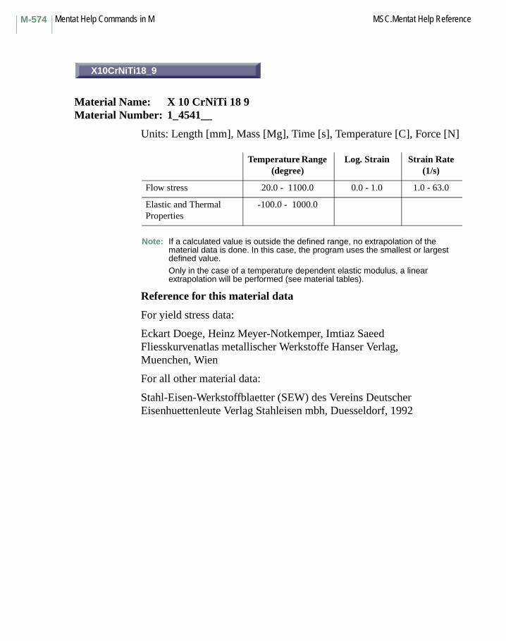
Mentat Help Commands in M MSC.Mentat Help ReferenceM-574
X10CrNiTi18_9
Material Name: X 10 CrNiTi 18 9Material Number: 1_4541__
Units: Length [mm], Mass [Mg], Time [s], Temperature [C], Force [N]
Note: If a calculated value is outside the defined range, no extrapolation of the material data is done. In this case, the program uses the smallest or largest defined value.
Only in the case of a temperature dependent elastic modulus, a linear extrapolation will be performed (see material tables).
Reference for this material data
For yield stress data:
Eckart Doege, Heinz Meyer-Notkemper, Imtiaz SaeedFliesskurvenatlas metallischer Werkstoffe Hanser Verlag,Muenchen, Wien
For all other material data:
Stahl-Eisen-Werkstoffblaetter (SEW) des Vereins Deutscher Eisenhuettenleute Verlag Stahleisen mbh, Duesseldorf, 1992
Temperature Range (degree)
Log. Strain Strain Rate (1/s)
Flow stress 20.0 - 1100.0 0.0 - 1.0 1.0 - 63.0
Elastic and Thermal Properties
-100.0 - 1000.0
X10CrNiTi18_9

M-575MSC.Mentat Help Reference Mentat Help Commands in M
X10CrNiMoTi18_10
Material Name: X 10 CrNiMoTi 18 10Material Number: 1_4571__
Units: Length [mm], Mass [Mg], Time [s], Temperature [C], Force [N]
Note: If a calculated value is outside the defined range, no extrapolation of the material data is done. In this case, the program uses the smallest or largest defined value.
Only in the case of a temperature dependent elastic modulus, a linear extrapolation will be performed (see material tables).
Reference for this material data
For yield stress data:
Eckart Doege, Heinz Meyer-Notkemper, Imtiaz SaeedFliesskurvenatlas metallischer Werkstoffe Hanser Verlag, Muenchen, Wien
For all other material data:
Stahl-Eisen-Werkstoffblaetter (SEW) des Vereins Deutscher Eisenhuettenleute Verlag Stahleisen mbh, Duesseldorf, 1992
Temperature Range (degree)
Log. Strain Strain Rate (1/s)
Flow stress 20.0 - 1100.0 0.0 - 1.0 1.0 - 63.0
Elastic and Thermal Properties
-100.0 - 1000.0
X10CrNiMoTi18_10

Mentat Help Commands in M MSC.Mentat Help ReferenceM-576
X20CrMoV12_1
Material Name: X 20 CrMoV 12 1Material Number: 1_4922__
Units: Length [mm], Mass [Mg], Time [s], Temperature [C], Force [N]
Note: If a calculated value is outside the defined range, no extrapolation of the material data is done. In this case, the program uses the smallest or largest defined value.
Only in the case of a temperature dependent elastic modulus, a linear extrapolation will be performed (see material tables).
Reference for this material data
For yield stress data:
Eckart Doege, Heinz Meyer-Notkemper, Imtiaz SaeedFliesskurvenatlas metallischer Werkstoffe Hanser Verlag,Muenchen, Wien
For all other material data:
Stahl-Eisen-Werkstoffblaetter (SEW) des Vereins Deutscher Eisenhuettenleute Verlag Stahleisen mbh, Duesseldorf, 1992
Temperature Range (degree)
Log. Strain Strain Rate (1/s)
Flow stress 950.0 - 1150.0 0.0 - 1.0 1.0 - 40.0
Elastic and Thermal Properties
20.0 - 600.0
X20CrMoV12_1
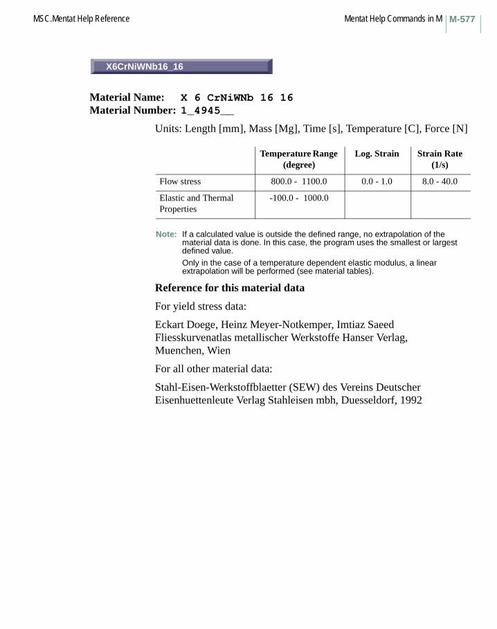
M-577MSC.Mentat Help Reference Mentat Help Commands in M
X6CrNiWNb16_16
Material Name: X 6 CrNiWNb 16 16Material Number: 1_4945__
Units: Length [mm], Mass [Mg], Time [s], Temperature [C], Force [N]
Note: If a calculated value is outside the defined range, no extrapolation of the material data is done. In this case, the program uses the smallest or largest defined value.
Only in the case of a temperature dependent elastic modulus, a linear extrapolation will be performed (see material tables).
Reference for this material data
For yield stress data:
Eckart Doege, Heinz Meyer-Notkemper, Imtiaz SaeedFliesskurvenatlas metallischer Werkstoffe Hanser Verlag,Muenchen, Wien
For all other material data:
Stahl-Eisen-Werkstoffblaetter (SEW) des Vereins Deutscher Eisenhuettenleute Verlag Stahleisen mbh, Duesseldorf, 1992
Temperature Range (degree)
Log. Strain Strain Rate (1/s)
Flow stress 800.0 - 1100.0 0.0 - 1.0 8.0 - 40.0
Elastic and Thermal Properties
-100.0 - 1000.0
X6CrNiWNb16_16

Mentat Help Commands in M MSC.Mentat Help ReferenceM-578
X12CrNiWTi16_13
Material Name: X 12 CrNiWTi 16 13Material Number: 1_4962__
Units: Length [mm], Mass [Mg], Time [s], Temperature [C], Force [N]
Note: If a calculated value is outside the defined range, no extrapolation of the material data is done. In this case, the program uses the smallest or largest defined value.
Only in the case of a temperature dependent elastic modulus, a linear extrapolation will be performed (see material tables).
Reference for this material data
For yield stress data:
Eckart Doege, Heinz Meyer-Notkemper, Imtiaz SaeedFliesskurvenatlas metallischer Werkstoffe Hanser Verlag,Muenchen, Wien
For all other material data:
Stahl-Eisen-Werkstoffblaetter (SEW) des Vereins Deutscher Eisenhuettenleute Verlag Stahleisen mbh, Duesseldorf, 1992
Temperature Range (degree)
Log. Strain Strain Rate (1/s)
Flow stress 800.0 - 1100.0 0.0 - 1.0 8.0 - 40.0
Elastic and Thermal Properties
-100.0 - 1000.0
X12CrNiWTi16_13
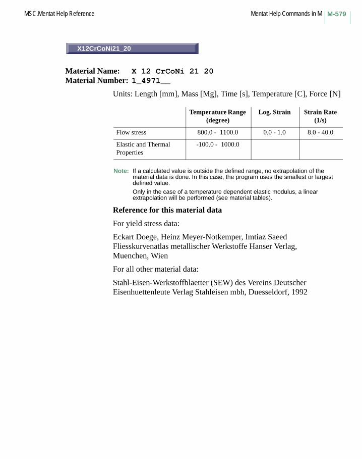
M-579MSC.Mentat Help Reference Mentat Help Commands in M
X12CrCoNi21_20
Material Name: X 12 CrCoNi 21 20Material Number: 1_4971__
Units: Length [mm], Mass [Mg], Time [s], Temperature [C], Force [N]
Note: If a calculated value is outside the defined range, no extrapolation of the material data is done. In this case, the program uses the smallest or largest defined value.
Only in the case of a temperature dependent elastic modulus, a linear extrapolation will be performed (see material tables).
Reference for this material data
For yield stress data:
Eckart Doege, Heinz Meyer-Notkemper, Imtiaz SaeedFliesskurvenatlas metallischer Werkstoffe Hanser Verlag,Muenchen, Wien
For all other material data:
Stahl-Eisen-Werkstoffblaetter (SEW) des Vereins Deutscher Eisenhuettenleute Verlag Stahleisen mbh, Duesseldorf, 1992
Temperature Range (degree)
Log. Strain Strain Rate (1/s)
Flow stress 800.0 - 1100.0 0.0 - 1.0 8.0 - 40.0
Elastic and Thermal Properties
-100.0 - 1000.0
X12CrCoNi21_20

Mentat Help Commands in M MSC.Mentat Help ReferenceM-580
X40CoCrNi20_20
Material Name: X 40 CoCrNi 20 20Material Number: 1_4977__
Units: Length [mm], Mass [Mg], Time [s], Temperature [C], Force [N]
Note: If a calculated value is outside the defined range no extrapolation of the material data is done. In this case, the program uses the smallest or largest defined value.
Only in the case of a temperature dependent elastic modulus a linear extrapolation will be performed (see material tables).
Reference for this material data
For yield stress data:
Eckart Doege, Heinz Meyer-Notkemper, Imtiaz SaeedFliesskurvenatlas metallischer Werkstoffe Hanser Verlag,Muenchen, Wien
For all other material data:
Stahl-Eisen-Werkstoffblaetter (SEW) des Vereins Deutscher Eisenhuettenleute Verlag Stahleisen mbh, Duesseldorf, 1992
Temperature Range (degree)
Log. Strain Strain Rate (1/s)
Flow stress 800.0 - 1100.0 0.0 - 1.0 8.0 - 40.0
Elastic and Thermal Properties
-100.0 - 1000.0
X40CoCrNi20_20

M-581MSC.Mentat Help Reference Mentat Help Commands in M
15CrNi6
Material Name: 15 CrNi 6Material Number: 1_5919__
Units: Length [mm], Mass [Mg], Time [s], Temperature [C], Force [N]
Note: If a calculated value is outside the defined range, no extrapolation of the material data is done. In this case, the program uses the smallest or largest defined value.
Only in the case of a temperature dependent elastic modulus, a linear extrapolation will be performed (see material tables).
Reference for this material data
For yield stress data:
Eckart Doege, Heinz Meyer-Notkemper, Imtiaz SaeedFliesskurvenatlas metallischer Werkstoffe Hanser Verlag,Muenchen, Wien
For all other material data:
Stahl-Eisen-Werkstoffblaetter (SEW) des Vereins Deutscher Eisenhuettenleute Verlag Stahleisen mbh, Duesseldorf, 1992
Temperature Range (degree)
Log. Strain Strain Rate (1/s)
Flow stress 20.0 - 1100.0 0.0 - 1.0 1.0 - 40.0
Elastic and Thermal Properties
-100.0 - 600.0
15CrNi6

Mentat Help Commands in M MSC.Mentat Help ReferenceM-582
X2NiCoMo18_9_5
Material Name: X 2 NiCoMo 18 9 5Material Number: 1_6358__
Units: Length [mm], Mass [Mg], Time [s], Temperature [C], Force [N]
Note: If a calculated value is outside the defined range, no extrapolation of the material data is done. In this case, the program uses the smallest or largest defined value.
Only in the case of a temperature dependent elastic modulus, a linear extrapolation will be performed (see material tables).
Reference for this material data
For yield stress data:
Eckart Doege, Heinz Meyer-Notkemper, Imtiaz SaeedFliesskurvenatlas metallischer Werkstoffe Hanser Verlag,Muenchen, Wien
For all other material data:
Stahl-Eisen-Werkstoffblaetter (SEW) des Vereins Deutscher Eisenhuettenleute Verlag Stahleisen mbh, Duesseldorf, 1992
Temperature Range (degree)
Log. Strain Strain Rate (1/s)
Flow stress 950.0 - 1250.0 0.0 - 1.0 1.0 - 40.0
Elastic and Thermal Properties
-100.0 - 400.0
X2NiCoMo18_9_5

M-583MSC.Mentat Help Reference Mentat Help Commands in M
15Cr3 (1)
Material Name: 15 Cr 3 Material Number: 1_7015_a
Units: Length [mm], Mass [Mg], Time [s], Temperature [C], Force [N]
Note: If a calculated value is outside the defined range, no extrapolation of the material data is done. In this case, the program uses the smallest or largest defined value.
Only in the case of a temperature dependent elastic modulus, a linear extrapolation will be performed (see material tables).
Reference for this material data
For yield stress data:
Eckart Doege, Heinz Meyer-Notkemper, Imtiaz SaeedFliesskurvenatlas metallischer Werkstoffe Hanser Verlag,Muenchen, Wien
For all other material data:
Stahl-Eisen-Werkstoffblaetter (SEW) des Vereins Deutscher Eisenhuettenleute Verlag Stahleisen mbh, Duesseldorf, 1992
Temperature Range (degree)
Log. Strain Strain Rate (1/s)
Flow stress 800.0 - 1200.0 0.0 - 1.0 1.6 - 40.0
Elastic and Thermal Properties
-100.0 - 600.0
15Cr3 (1)

Mentat Help Commands in M MSC.Mentat Help ReferenceM-584
15Cr3 (2)
Material Name: 15 Cr 3 Material Number: 1_7015_b
Units: Length [mm], Mass [Mg], Time [s], Temperature [C], Force [N]
Note: If a calculated value is outside the defined range, no extrapolation of the material data is done. In this case, the program uses the smallest or largest defined value.
Only in the case of a temperature dependent elastic modulus, a linear extrapolation will be performed (see material tables).
Reference for this material data
For yield stress data:
Eckart Doege, Heinz Meyer-Notkemper, Imtiaz SaeedFliesskurvenatlas metallischer Werkstoffe Hanser Verlag,Muenchen, Wien
For all other material data:
Stahl-Eisen-Werkstoffblaetter (SEW) des Vereins Deutscher Eisenhuettenleute Verlag Stahleisen mbh, Duesseldorf, 1992
Temperature Range (degree)
Log. Strain Strain Rate (1/s)
Flow stress 20.0 - 500.0 0.0 - 1.0 8.0 - 8.0
Elastic and Thermal Properties
-100.0 - 600.0
15Cr3 (2)

M-585MSC.Mentat Help Reference Mentat Help Commands in M
15Cr3 (h)
Material Name: 15 Cr 3 Material Number: 1_7015_h
Units: Length [mm], Mass [Mg], Time [s], Temperature [C], Force [N]
Note: If a calculated value is outside the defined range, no extrapolation of the material data is done. In this case, the program uses the smallest or largest defined value.
Only in the case of a temperature dependent elastic modulus, a linear extrapolation will be performed (see material tables).
Reference for this material data
For yield stress data:
Eckart Doege, Heinz Meyer-Notkemper, Imtiaz SaeedFliesskurvenatlas metallischer Werkstoffe Hanser Verlag,Muenchen, Wien
For all other material data:
Stahl-Eisen-Werkstoffblaetter (SEW) des Vereins Deutscher Eisenhuettenleute Verlag Stahleisen mbh, Duesseldorf, 1992
Temperature Range (degree)
Log. Strain Strain Rate (1/s)
Flow stress 20.0 - 600.0 0.0 - 1.0 1.6 - 40.0
Elastic and Thermal Properties
-100.0 - 600.0
15Cr3 (h)

Mentat Help Commands in M MSC.Mentat Help ReferenceM-586
15Cr3 (w)
Material Name: 15 Cr 3Material Number: 1_7015_w
Units: Length [mm], Mass [Mg], Time [s], Temperature [C], Force [N]
Note: If a calculated value is outside the defined range, no extrapolation of the material data is done. In this case, the program uses the smallest or largest defined value.
Only in the case of a temperature dependent elastic modulus, a linear extrapolation will be performed (see material tables).
Reference for this material data
For yield stress data:
Eckart Doege, Heinz Meyer-Notkemper, Imtiaz SaeedFliesskurvenatlas metallischer Werkstoffe Hanser Verlag,Muenchen, Wien
For all other material data:
Stahl-Eisen-Werkstoffblaetter (SEW) des Vereins Deutscher Eisenhuettenleute Verlag Stahleisen mbh, Duesseldorf, 1992
Temperature Range (degree)
Log. Strain Strain Rate (1/s)
Flow stress 20.0 - 600.0 0.0 - 1.0 1.6 - 40.0
Elastic and Thermal Properties
-100.0 - 600.0
15Cr3 (w)

M-587MSC.Mentat Help Reference Mentat Help Commands in M
41Cr4
Material Name: 41 Cr 4Material Number: 1_7035__
Units: Length [mm], Mass [Mg], Time [s], Temperature [C], Force [N]
Note: If a calculated value is outside the defined range, no extrapolation of the material data is done. In this case, the program uses the smallest or largest defined value.
Only in the case of a temperature dependent elastic modulus, a linear extrapolation will be performed (see material tables).
Reference for this material data
For yield stress data:
Eckart Doege, Heinz Meyer-Notkemper, Imtiaz SaeedFliesskurvenatlas metallischer Werkstoffe Hanser Verlag, Muenchen, Wien
For all other material data:
Stahl-Eisen-Werkstoffblaetter (SEW) des Vereins Deutscher Eisenhuettenleute Verlag Stahleisen mbh, Duesseldorf, 1992
Temperature Range (degree)
Log. Strain Strain Rate (1/s)
Flow stress 800.0 - 1200.0 0.0 - 1.0 1.6 - 40.0
Elastic and Thermal Properties
-100.0 - 600.0
41Cr4

Mentat Help Commands in M MSC.Mentat Help ReferenceM-588
41Cr4 (g)
Material Name: 41 Cr 4Material Number: 1_7035_g
Units: Length [mm], Mass [Mg], Time [s], Temperature [C], Force [N]
Note: If a calculated value is outside the defined range, no extrapolation of the material data is done. In this case, the program uses the smallest or largest defined value.
Only in the case of a temperature dependent elastic modulus, a linear extrapolation will be performed (see material tables).
Reference for this material data
For yield stress data:
Eckart Doege, Heinz Meyer-Notkemper, Imtiaz SaeedFliesskurvenatlas metallischer Werkstoffe Hanser Verlag,Muenchen, Wien
For all other material data:
Stahl-Eisen-Werkstoffblaetter (SEW) des Vereins Deutscher Eisenhuettenleute Verlag Stahleisen mbh, Duesseldorf, 1992
Temperature Range (degree)
Log. Strain Strain Rate (1/s)
Flow stress 20.0 - 500.0 0.0 - 1.0 1.6 - 40.0
Elastic and Thermal Properties
-100.0 - 600.0
41Cr4 (g)

M-589MSC.Mentat Help Reference Mentat Help Commands in M
41Cr4 (h)
Material Name: 41 Cr 4Material Number: 1_7035_h
Units: Length [mm], Mass [Mg], Time [s], Temperature [C], Force [N]
Note: If a calculated value is outside the defined range, no extrapolation of the material data is done. In this case, the program uses the smallest or largest defined value.
Only in the case of a temperature dependent elastic modulus, a linear extrapolation will be performed (see material tables).
Reference for this material data
For yield stress data:
Eckart Doege, Heinz Meyer-Notkemper, Imtiaz SaeedFliesskurvenatlas metallischer Werkstoffe Hanser Verlag,Muenchen, Wien
For all other material data:
Stahl-Eisen-Werkstoffblaetter (SEW) des Vereins Deutscher Eisenhuettenleute Verlag Stahleisen mbh, Duesseldorf, 1992
Temperature Range (degree)
Log. Strain Strain Rate (1/s)
Flow stress 200.0 - 600.0 0.0 - 1.0 1.60 - 40.0
Elastic and Thermal Properties
-100.0 - 600.0
41Cr4 (h)

Mentat Help Commands in M MSC.Mentat Help ReferenceM-590
41Cr4 (n)
Material Name: 41 Cr 4 Material Number: 1_7035_n
Units: Length [mm], Mass [Mg], Time [s], Temperature [C], Force [N]
Note: If a calculated value is outside the defined range, no extrapolation of the material data is done. In this case, the program uses the smallest or largest defined value.
Only in the case of a temperature dependent elastic modulus, a linear extrapolation will be performed (see material tables).
Reference for this material data
For yield stress data:
Eckart Doege, Heinz Meyer-Notkemper, Imtiaz SaeedFliesskurvenatlas metallischer Werkstoffe Hanser Verlag, Muenchen, Wien
For all other material data:
Stahl-Eisen-Werkstoffblaetter (SEW) des Vereins Deutscher Eisenhuettenleute Verlag Stahleisen mbh, Duesseldorf, 1992
Temperature Range (degree)
Log. Strain Strain Rate (1/s)
Flow stress 800.0 - 1100.0 0.0 - 1.0 8.0 - 40.0
Elastic and Thermal Properties
-100.0 - 600.0
41Cr4 (n)

M-591MSC.Mentat Help Reference Mentat Help Commands in M
41Cr4 (w)
Material Name: 41 Cr 4Material Number: 1_7035_w
Units: Length [mm], Mass [Mg], Time [s], Temperature [C], Force [N]
Note: If a calculated value is outside the defined range, no extrapolation of the material data is done. In this case, the program uses the smallest or largest defined value.
Only in the case of a temperature dependent elastic modulus, a linear extrapolation will be performed (see material tables).
Reference for this material data
For yield stress data:
Eckart Doege, Heinz Meyer-Notkemper, Imtiaz SaeedFliesskurvenatlas metallischer Werkstoffe Hanser Verlag,Muenchen, Wien
For all other material data:
Stahl-Eisen-Werkstoffblaetter (SEW) des Vereins Deutscher Eisenhuettenleute Verlag Stahleisen mbh, Duesseldorf, 1992
Temperature Range (degree)
Log. Strain Strain Rate (1/s)
Flow stress 20.0 - 600.0 0.0 - 1.0 1.6 - 40.0
Elastic and Thermal Properties
-100.0 - 600.0
41Cr4 (w)

Mentat Help Commands in M MSC.Mentat Help ReferenceM-592
16MnCr5
Material Name: 16 MnCr 5Material Number: 1_7131__
Units: Length [mm], Mass [Mg], Time [s], Temperature [C], Force [N]
Note: If a calculated value is outside the defined range, no extrapolation of the material data is done. In this case, the program uses the smallest or largest defined value.
Only in the case of a temperature dependent elastic modulus, a linear extrapolation will be performed (see material tables).
Reference for this material data
For yield stress data:
Eckart Doege, Heinz Meyer-Notkemper, Imtiaz SaeedFliesskurvenatlas metallischer Werkstoffe Hanser Verlag,Muenchen, Wien
For all other material data:
Stahl-Eisen-Werkstoffblaetter (SEW) des Vereins Deutscher Eisenhuettenleute Verlag Stahleisen mbh, Duesseldorf, 1992
Temperature Range (degree)
Log. Strain Strain Rate (1/s)
Flow stress 20.0 - 1100.0 0.0 - 1.0 1.6 - 40.0
Elastic and Thermal Properties
-100.0 - 600.0
16MnCr5

M-593MSC.Mentat Help Reference Mentat Help Commands in M
20MnCr5
Material Name: 20 MnCr 5Material Number: 1_7147__
Units: Length [mm], Mass [Mg], Time [s], Temperature [C], Force [N]
Note: If a calculated value is outside the defined range, no extrapolation of the material data is done. In this case, the program uses the smallest or largest defined value.
Only in the case of a temperature dependent elastic modulus, a linear extrapolation will be performed (see material tables).
Reference for this material data
For yield stress data:
Eckart Doege, Heinz Meyer-Notkemper, Imtiaz SaeedFliesskurvenatlas metallischer Werkstoffe Hanser Verlag,Muenchen, Wien
For all other material data:
Stahl-Eisen-Werkstoffblaetter (SEW) des Vereins Deutscher Eisenhuettenleute Verlag Stahleisen mbh, Duesseldorf, 1992
Temperature Range (degree)
Log. Strain Strain Rate (1/s)
Flow stress 20.0 - 800.0 0.0 - 1.0 40.0 - 40.0
Elastic and Thermal Properties
-100.0 - 600.0
20MnCr5

Mentat Help Commands in M MSC.Mentat Help ReferenceM-594
42CrMo4 (2)
Material Name: 42 CrMo 4Material Number: 1_7225__
Units: Length [mm], Mass [Mg], Time [s], Temperature [C], Force [N]
Note: If a calculated value is outside the defined range, no extrapolation of the material data is done. In this case, the program uses the smallest or largest defined value.
Only in the case of a temperature dependent elastic modulus, a linear extrapolation will be performed (see material tables).
Reference for this material data
For yield stress data:
Eckart Doege, Heinz Meyer-Notkemper, Imtiaz SaeedFliesskurvenatlas metallischer Werkstoffe Hanser Verlag,Muenchen, Wien
For all other material data:
Stahl-Eisen-Werkstoffblaetter (SEW) des Vereins Deutscher Eisenhuettenleute Verlag Stahleisen mbh, Duesseldorf, 1992
Temperature Range (degree)
Log. Strain Strain Rate (1/s)
Flow stress 800.0 - 1200.0 0.0 - 1.0 1.6 - 40.0
Elastic and Thermal Properties
-100.0 - 600.0
42CrMo4 (2)

M-595MSC.Mentat Help Reference Mentat Help Commands in M
42CrMo4 (1)
Material Name: 42 CrMo 4Material Number: 1_7225_1
Units: Length [mm], Mass [Mg], Time [s], Temperature [C], Force [N]
Note: If a calculated value is outside the defined range, no extrapolation of the material data is done. In this case, the program uses the smallest or largest defined value.
Only in the case of a temperature dependent elastic modulus, a linear extrapolation will be performed (see material tables).
Reference for this material data
For yield stress data:
Eckart Doege, Heinz Meyer-Notkemper, Imtiaz SaeedFliesskurvenatlas metallischer Werkstoffe Hanser Verlag,Muenchen, Wien
For all other material data:
Stahl-Eisen-Werkstoffblaetter (SEW) des Vereins Deutscher Eisenhuettenleute Verlag Stahleisen mbh, Duesseldorf, 1992
Temperature Range (degree)
Log. Strain Strain Rate (1/s)
Flow stress 20.0 - 1200.0 0.0 - 1.0 40.0 - 40.0
Elastic and Thermal Properties
-100.0 - 600.0
42CrMo4 (1)

Mentat Help Commands in M MSC.Mentat Help ReferenceM-596
42CrMo4 (h)
Material Name: 42 CrMo 4Material Number: 1_7225_h
Units: Length [mm], Mass [Mg], Time [s], Temperature [C], Force [N]
Note: If a calculated value is outside the defined range, no extrapolation of the material data is done. In this case, the program uses the smallest or largest defined value.
Only in the case of a temperature dependent elastic modulus, a linear extrapolation will be performed (see material tables).
Reference for this material data
For yield stress data:
Eckart Doege, Heinz Meyer-Notkemper, Imtiaz SaeedFliesskurvenatlas metallischer Werkstoffe Hanser Verlag,Muenchen, Wien
For all other material data:
Stahl-Eisen-Werkstoffblaetter (SEW) des Vereins Deutscher Eisenhuettenleute Verlag Stahleisen mbh, Duesseldorf, 1992
Temperature Range (degree)
Log. Strain Strain Rate (1/s)
Flow stress 600.0 - 600.0 0.0 - 1.0 1.6 - 40.0
Elastic and Thermal Properties
-100.0 - 600.0
42CrMo4 (h)

M-597MSC.Mentat Help Reference Mentat Help Commands in M
42CrMo4 (w)
Material Name: 42 CrMo 4Material Number: 1_7225_w
Units: Length [mm], Mass [Mg], Time [s], Temperature [C], Force [N]
Note: If a calculated value is outside the defined range, no extrapolation of the material data is done. In this case, the program uses the smallest or largest defined value.
Only in the case of a temperature dependent elastic modulus, a linear extrapolation will be performed (see material tables).
Reference for this material data
For yield stress data:
Eckart Doege, Heinz Meyer-Notkemper, Imtiaz SaeedFliesskurvenatlas metallischer Werkstoffe Hanser Verlag,Muenchen, Wien
For all other material data:
Stahl-Eisen-Werkstoffblaetter (SEW) des Vereins Deutscher Eisenhuettenleute Verlag Stahleisen mbh, Duesseldorf, 1992
Temperature Range (degree)
Log. Strain Strain Rate (1/s)
Flow stress 20.0 - 600.0 0.0 - 1.0 1.6 - 40.0
Elastic and Thermal Properties
-100.0 - 600.0
42CrMo4 (w)

Mentat Help Commands in M MSC.Mentat Help ReferenceM-598
16CrMo4
Material Name: 16 CrMo 4Material Number: 1_7242__
Units: Length [mm], Mass [Mg], Time [s], Temperature [C], Force [N]
Note: If a calculated value is outside the defined range, no extrapolation of the material data is done. In this case, the program uses the smallest or largest defined value.
Only in the case of a temperature dependent elastic modulus, a linear extrapolation will be performed (see material tables).
Reference for this material data
For yield stress data:
Eckart Doege, Heinz Meyer-Notkemper, Imtiaz SaeedFliesskurvenatlas metallischer Werkstoffe Hanser Verlag,Muenchen, Wien
For all other material data:
Stahl-Eisen-Werkstoffblaetter (SEW) des Vereins Deutscher Eisenhuettenleute Verlag Stahleisen mbh, Duesseldorf, 1992
Temperature Range (degree)
Log. Strain Strain Rate (1/s)
Flow stress 800.0 - 1200.0 0.0 - 1.0 1.6 - 40.0
Elastic and Thermal Properties
-100.0 - 600.0
16CrMo4

M-599MSC.Mentat Help Reference Mentat Help Commands in M
16CrMo4 (w)
Material Name: 16 CrMo 4Material Number: 1_7242_w
Units: Length [mm], Mass [Mg], Time [s], Temperature [C], Force [N]
Note: If a calculated value is outside the defined range, no extrapolation of the material data is done. In this case, the program uses the smallest or largest defined value.
Only in the case of a temperature dependent elastic modulus, a linear extrapolation will be performed (see material tables).
Reference for this material data
For yield stress data:
Eckart Doege, Heinz Meyer-Notkemper, Imtiaz SaeedFliesskurvenatlas metallischer Werkstoffe Hanser Verlag,Muenchen, Wien
For all other material data:
Stahl-Eisen-Werkstoffblaetter (SEW) des Vereins Deutscher Eisenhuettenleute Verlag Stahleisen mbh, Duesseldorf, 1992
Temperature Range (degree)
Log. Strain Strain Rate (1/s)
Flow stress 20.0 - 600.0 0.0 - 1.0 1.6 - 40.0
Elastic and Thermal Properties
-100.0 - 600.0
16CrMo4 (w)

Mentat Help Commands in M MSC.Mentat Help ReferenceM-600
20MoCr4
Material Name: 20 MoCr 4Material Number: 1_7321__
Units: Length [mm], Mass [Mg], Time [s], Temperature [C], Force [N]
Note: If a calculated value is outside the defined range, no extrapolation of the material data is done. In this case, the program uses the smallest or largest defined value.
Only in the case of a temperature dependent elastic modulus, a linear extrapolation will be performed (see material tables).
Reference for this material data
For yield stress data:
Eckart Doege, Heinz Meyer-Notkemper, Imtiaz SaeedFliesskurvenatlas metallischer Werkstoffe Hanser Verlag,Muenchen, Wien
For all other material data:
Stahl-Eisen-Werkstoffblaetter (SEW) des Vereins Deutscher Eisenhuettenleute Verlag Stahleisen mbh, Duesseldorf, 1992
Temperature Range (degree)
Log. Strain Strain Rate (1/s)
Flow stress 20.0 - 500.0 0.0 - 1.0 1.6 - 40.0
Elastic and Thermal Properties
-100.0 - 600.0
20MoCr4

M-601MSC.Mentat Help Reference Mentat Help Commands in M
NAME
Command: material_name
Description: This command sets or changes the name of the current material.
A material is a collection of information that describes a material to be applied to elements in the model. Materials contain the material type, material properties, tables or functions that apply to those properties, and options that will be applied to the specified set of elements during analysis. Multiple materials may be defined and are stored in the list of currently defined materials.
Keyboard Command Sequence:
material_name <material name>
ELASTIC-PLASTIC
Command: material_option
Description: This command sets an option for the current material. Options vary depending on the material type.
The option to be set is designated by the material type, the option name, and the desired value separated by colons.For example, modal damping method for a dynamic material is designated as dynamic:method:modal. The value or choice for an option is always specified as a label.
Keyboard Command Sequence:
material_option <material type>:<option name>:<choice>
Other Buttons with the same description:
ADDITIVE DECOMPOSITIONANISOTROPICBINGHAMBUYUKOZTURK CONCRETECAM CLAYCARREAUCOMBINEDCONSTANT
NAME
ELASTIC-PLASTIC

Mentat Help Commands in M MSC.Mentat Help ReferenceM-602
COWPER-SYMONDSDATABASE VALUESDEF. GRADIENT DEF. GRADIENT DEF. GRADIENT, ROTATION TENSOR STRETCH RATIOS ROTATION TENSODEF. GRADIENT DEF. GRADIENT, ROTATION TENSOR STRETCH RATIOSDEF. GRADIENT, ROTATION TENSORENTERED VALUESFULL ALPHA RESET ORNLGENERALIZED PLASTICITYGENERALIZED POWER LAWHILLHOFFMANISOTROPICJOHNSON-COOKKINEMATICKUMARLINEARLINEAR MOHR-COULOMBMAXIMUM STRAINMAXIMUM STRESSMULTIPLICATIVE DECOMPOSITIONNARAYANASWAMYNEWTONIANNONENONEOAK RIDGE NATIONAL LABORTHOTROPICPARABOLIC MOHR-COULOMBPIECEWISE LINEARPIECEWISE-LINEARPLASTIC STRAIN CONTROLPOWER LAWPOWER SERIESPROGRESSIVE FAILURERATE POWER LAWREVERSED PLASTICITY ORNLRIGID-PLASTICSTRAIN DEPENDENTSTRESS CONTROLTSAI-WUUSER SUB. USER SUB. ANEXPUSER SUB. ANKONDUSER SUB. CRPLAWUSER SUB. HYPELAUSER SUB. HYPELA2USER SUB. TRSFACUSER SUB. UBEAMUSER SUB. UCRACKUSER SUB. UEPSUSER SUB. UFAILUSER SUB. UGRAINUSER SUB. UMUUSER SUB. UNEWTNUSER SUB. UPHIUSER SUB. UVOIDNUSER SUBROUTINE UELDAM

M-603MSC.Mentat Help Reference Mentat Help Commands in M
USER SUBS. ANELAS, HOOKLW, ANPUSER SUBS. UEPS,nUMU, USIGMAVISCOELASTICVISCOPLASTICITY (UVSCPL)VON MISESWILLIAMS-LANDEL-FERRYYADA
READ
Command: material_read
Description: This command reads a material model file and imports the materials into the current model.
Keyboard Command Sequence:
material_read <material model name>
Another Button with the same description:
READ OTHER MATERIAL
REMOVE
Command: material_remove_type
Description: Removes the specified type or subtype from the current material. You must specify the material type or subtype (see material_type).
Keyboard Command Sequence:
material_remove_type <type>material_remove_type <type>:<mechanical type
option>material_remove_type <subtype>material_remove_type <subtype>:<subtype option>
READ
REMOVE

Mentat Help Commands in M MSC.Mentat Help ReferenceM-604
RESET
Command: material_reset
Description: This command resets the values of the specified material subtype to their initial default values. You must specify the material type or subtype (see material_type).
Keyboard Command Sequence:
material_reset <type>material_reset <type>:<mechanical type option>material_reset <subtype>material_reset <subtype>:<subtype option>
material_table
Command: material_table
Description: This command adds a table for a property in the current material. A table is a function that makes the property value dependent on another variable during analysis.
The property to receive the table is designated by the material type and the property name separated by a colon, and an appended table number. For example, a table for Young’s modulus in anisotropic material is designated as isotropic:e0. Table numbers start at zero.
Note that only certain properties may have tables associated with them. Refer to Marc material model descriptions to determine which properties can have tables.
The table specified for the property must have already been created.
Keyboard Command Sequence:
material_table <material type>:<property name><table number> <table name>
RESET
material_table
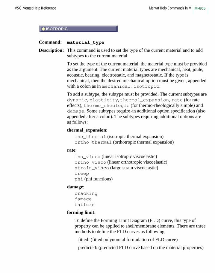
M-605MSC.Mentat Help Reference Mentat Help Commands in M
ISOTROPIC
Command: material_type
Description: This command is used to set the type of the current material and to add subtypes to the current material.
To set the type of the current material, the material type must be provided as the argument. The current material types are mechanical, heat, joule, acoustic, bearing, electrostatic, and magnetostatic. If the type is mechanical, then the desired mechanical option must be given, appended with a colon as in mechanical:isotropic.
To add a subtype, the subtype must be provided. The current subtypes are dynamic, plasticity, thermal_expansion, rate (for rate effects), thermo_rheologic (for thermo-rheologically simple) and damage. Some subtypes require an additional option specification (also appended after a colon). The subtypes requiring additional options are as follows:
thermal_expansion:iso_thermal (isotropic thermal expansion)ortho_thermal (orthotropic thermal expansion)
rate:iso_visco (linear isotropic viscoelastic)ortho_visco (linear orthotropic viscoelastic)strain_visco (large strain viscoelastic)creepphi (phi functions)
damage:crackingdamagefailure
forming limit:
To define the Forming Limit Diagram (FLD) curve, this type of property can be applied to shell/membrane elements. There are three methods to define the FLD curves as following:
fitted: (fitted polynomial formulation of FLD curve)
predicted: (predicted FLD curve based on the material properties)
ISOTROPIC

Mentat Help Commands in M MSC.Mentat Help ReferenceM-606
table: (table form definition for FLD curve)
Reference: MSC.Marc Volume A: Theory and Information.
Keyboard Command Sequence:
material_type <type>material_type <type>:<mechanical type option>material_type <subtype>material_type <subtype>:<subtype option>
Other Buttons with the same description:
ACOUSTICANISOTROPICARRUDA-BOYCEBEARINGCRACKINGCREEPDAMAGEDAMPINGELASTIC-PLASTICELECTROMAGNETICELECTROSTATICFAILUREFLUIDFOAMGENTGRAIN SIZEHEAT TRANSFERHYPOELASTICJOULE HEATINGLATENT HEATMAGNETOSTATICMOONEYOGDENOKORTHOTROPICPHIPLASTICITYPOWDERRUBBERSOILTHERMAL EXP.THERMO-RHEOLOGICALLY SIMPLEVISCOELASTIC
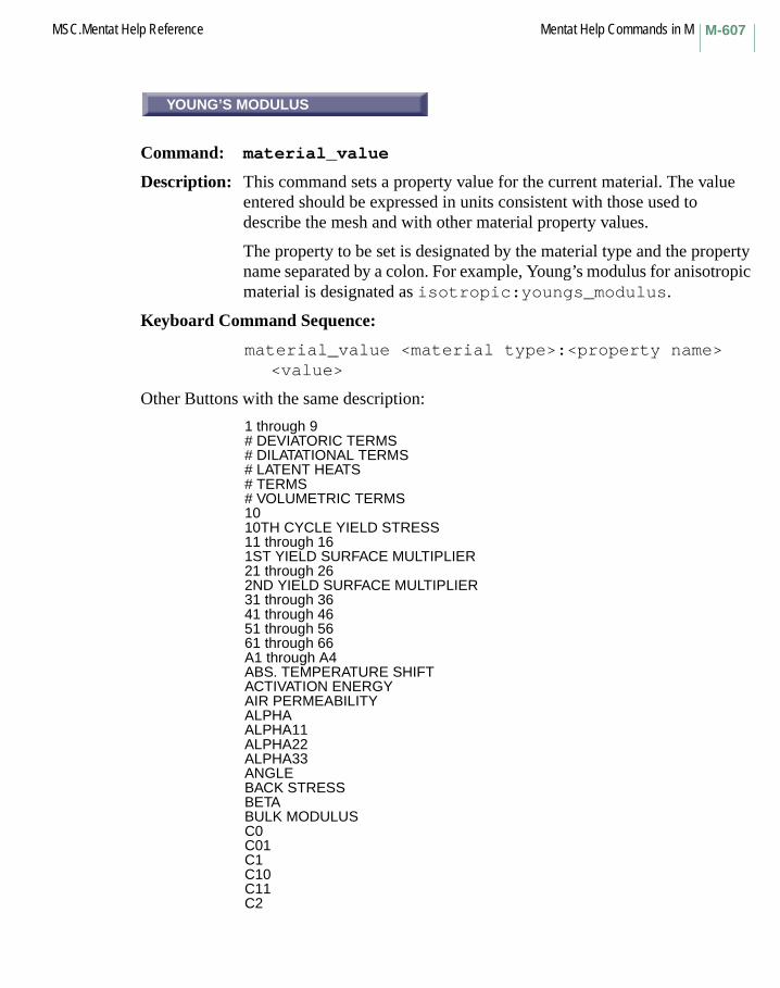
M-607MSC.Mentat Help Reference Mentat Help Commands in M
YOUNG’S MODULUS
Command: material_value
Description: This command sets a property value for the current material. The value entered should be expressed in units consistent with those used to describe the mesh and with other material property values.
The property to be set is designated by the material type and the property name separated by a colon. For example, Young’s modulus for anisotropic material is designated as isotropic:youngs_modulus.
Keyboard Command Sequence:
material_value <material type>:<property name><value>
Other Buttons with the same description:
1 through 9# DEVIATORIC TERMS# DILATATIONAL TERMS# LATENT HEATS# TERMS# VOLUMETRIC TERMS1010TH CYCLE YIELD STRESS11 through 161ST YIELD SURFACE MULTIPLIER21 through 262ND YIELD SURFACE MULTIPLIER31 through 3641 through 4651 through 5661 through 66A1 through A4ABS. TEMPERATURE SHIFTACTIVATION ENERGYAIR PERMEABILITYALPHAALPHA11ALPHA22ALPHA33ANGLEBACK STRESSBETABULK MODULUSC0C01C1C10C11C2
YOUNG’S MODULUS
Mentat Help Commands in M MSC.Mentat Help ReferenceM-608
C20C3C30C4C5CAV. PRESSURECHAIN LENGTHCOEFFICIENTCOEFFICIENT ACOEFFICIENT BCOEFFICIENT B0COEFFICIENT B1COEFFICIENT B2COEFFICIENT B3COEFFICIENT B4COEFFICIENT B5COEFFICIENT B6COEFFICIENT CCOEFFICIENT NCOMPRESSION RATIOCONDUCTIVITYCONDUCTIVITY1CONDUCTIVITY11CONDUCTIVITY12CONDUCTIVITY13CONDUCTIVITY2CONDUCTIVITY22CONDUCTIVITY23CONDUCTIVITY3CONDUCTIVITY33CRITICAL STATE CURVE SLOPECRITICAL STRESSCRITICAL VOID VOLUME FRACTIONCRUSHING STRAINCUTOFF STRAIN RATEDYNAMIC VISCOSITYE11 through E33EMISSIVITYEXPONENTEXPONENT MEXPONENT NFAILURE INDEXFAILURE VOID VOLUME FRACTIONFLUID BULK MODULUSFLUID DRAGFRACTION PARAMETERG12G23G31GAMMAGLOBAL LAYER IDH-B RELATIONH-B RELATION11H-B RELATION22H-B RELATION33INITIAL GRAIN SIZEINITIAL STRAIN RATE

M-609MSC.Mentat Help Reference Mentat Help Commands in M
INITIAL VOID VOLUME FRACTIONINITIAL YIELD STRESSINTERACTIVE STRENGTH TENSOR XYINTERACTIVE STRENGTH TENSOR YZINTERACTIVE STRENGTH TENSOR ZXINV PERMEABILITYINV PERMEABILITY11INV PERMEABILITY22INV PERMEABILITY33INVERSE EXPONENT PKLIQUID COEFMASS DENSITYMASS MATRIX MULTIPLIERMAX COMPRESSIVE STRAIN XMAX COMPRESSIVE STRAIN YMAX COMPRESSIVE STRAIN ZMAX COMPRESSIVE STRESS XMAX COMPRESSIVE STRESS YMAX COMPRESSIVE STRESS ZMAX SHEAR STRAIN XYMAX SHEAR STRAIN YZMAX SHEAR STRAIN ZXMAX SHEAR STRESS XYMAX SHEAR STRESS YZMAX SHEAR STRESS ZXMAX TENSILE STRAIN XMAX TENSILE STRAIN YMAX TENSILE STRAIN ZMAX TENSILE STRESS XMAX TENSILE STRESS YMAX TENSILE STRESS ZMAX. 1ST INVARIANTMELT TEMPERATUREMULTIPLIERNNKTNU12NU23NU31PERMEABILITYPERMEABILITY11PERMEABILITY22PERMEABILITY33PERMITTIVITYPERMITTIVITY11PERMITTIVITY22PERMITTIVITY33POISSON RATIOPOISSON’S RATIOREBAR AREARECOMPRESSION RATIOREF PLANEREF. TEMPERATUREREL. LAYER POSITIONRESISTIVITYRESISTIVITY11
Mentat Help Commands in M MSC.Mentat Help ReferenceM-610
RESISTIVITY22RESISTIVITY33ROOM TEMPERATURESCALAR FACTOR @ INFSHEAR RETENTIONSOFTENING MODULUSSOLID COEFSPECIFIC HEATSTANDARD DEVIATIONSTIFFNESS MATRIX MULTIPLIERSTRUCT. RELAX. REF. TEMP.TENSILE MODULUSTHERMAL EXP. COEF.THERMAL EXPANSIONTHICKNESSVISCOSITYVISCOSITY @ INF.VOLUME FRACTION FOR VOID NUCLEVOLUMETRIC EXP.XYYIELD STRENGTHYIELD STRESSYRDIR1YRDIR2YRDIR3YRSHR1YRSHR2YRSHR3Z
max_curve_divisions
Command: max_curve_divisions
Description: This command assures that the number of edge divisions on the list of given curves is no greater than the given number.
Keyboard Command Sequence:
max_curve_divisions <number of divisions><curve list>
max_curve_divisions

M-611MSC.Mentat Help Reference Mentat Help Commands in M
MEMORY
Command: memory
Description: This command prints the current MSC.Marc Mentat memory usage on standard output.
Keyboard Command Sequence:
memory
MENU EXECUTE
Command: menu_execute
Description: This command specifies whether or not menu commands entered through the dialog area will be executed.
Keyboard Command Sequence:
menu_execute <on or off>
MENU RECORD
Command: menu_record
Description: This command specifies whether or not menu commands are recorded in the dialog area.
Keyboard Command Sequence:
menu_record <on or off>
MEMORY
MENU EXECUTE
MENU RECORD
Mentat Help Commands in M MSC.Mentat Help ReferenceM-612
MERGE DUPLICATE BOUND CONDS
Command: merge_applies
Description: This command merges loads and boundary conditions which have identical data.
Keyboard Command Sequence:
merge_applies
MERGE
Command: merge_models
Description: This command merges a MSC.Marc Mentat model database with the current model. The current model is preserved. To replace the current model with a new model, use the open_model command.
Keyboard Command Sequence:
merge_model <model name>
TRANSITION
Command: set_mesh_transition
Description: This command sets mesh transition parameter. Its default value is 1.
When the value is bigger than 1, the element size at the central area will be larger.
When the value is smaller than 1, the element size at the central area will be smaller.
Keyboard Command Sequence:
set_mesh_transition <value>
MERGE DUPLICATE BOUND CONDS
MERGE
TRANSITION
M-613MSC.Mentat Help Reference Mentat Help Commands in M
MESH GENERATION
Menu: MESH GENERATION
Description: This menu contains mesh generation commands which are used to create and/or edit geometry and element meshes. Functionality includes adding, removing, and editing nodes, elements, points, curves, and surfaces of new or existing meshes.
In addition to these basic functions, the MESH GENERATION menu contains several submenus that contain commands for transforming the mesh.
message
Command: message
Description: This command displays any text which follows it. This may be useful for commenting the output generated from a MSC.Marc Mentat procedure file.
Keyboard Command Sequence:
message Put your message here....
min_curve_divisions
Command: min_curve_divisions
Description: This command assures that the number of edge divisions on the list of given curves is no less than the given number.
Keyboard Command Sequence:
min_curve_divisions <number of divisions><curve list>
MESH GENERATION
message
min_curve_divisions
Mentat Help Commands in M MSC.Mentat Help ReferenceM-614
DESCRIPTION
Menu: MODEL DESCRIPTION
Description: This menu allows the user to set the description for the current model.
The text field is used for entering the description. Either a return typed into the text field or clicking on the OK button will cause the model_description command to be executed and close the popup menu.
Clicking the RESET button resets the text field to the current model description.
Clicking the CANCEL button closes the popup menu without executing the command.
Keyboard Command Sequence:
model_description <model description>
Other Buttons with the same description:
CANCELOK
MONITOR
Command: monitor_job
Description: This command updates the status of a job on a periodic basis in order to provide a means of watching the progress of an analysis without the interaction of the user. The command is terminated by any input by the user.
Keyboard Command Sequence:
monitor_job
DESCRIPTION
MONITOR

M-615MSC.Mentat Help Reference Mentat Help Commands in M
MOONEY(2)
Command: xcv_model mooney2
Description: This command is used if experimental data must be fitted using the two term Mooney-Rivlin strain energy function W, which is given by:
W = C10*(I1 - 3) + C01*(I2 - 3)
where I1 and I2 are the first and second invariant of the right Cauchy-Green strain tensor and C10 and C01 are the material parameters to be determined.
For this model, a volumetric test cannot be supplied. The user may enter a bulk modulus (material_type mechanical:mooney).If no bulk modulus is given, Marc assumes (nearly) incompressible material behavior.
Keyboard Command Sequence:
xcv_model mooney2
MOONEY(3)
Command: xcv_model mooney3
Description: This command is used if experimental data must be fitted using the three term Mooney-Rivlin strain energy function W, which is given by:
W = C10*(I1 - 3) + C01*(I2 - 3) + C11*(I1 - 3)*(I2 - 3)
where I1 and I2 are the first and second invariant of the right Cauchy-Green strain tensor and C10, C01, and C11 are the material parameters to be determined.
For this model, a volumetric test cannot be supplied. The user may enter a bulk modulus (material_type mechanical:mooney).If no bulk modulus is given, Marc assumes (nearly) incompressible material behavior.
Keyboard Command Sequence:
xcv_model mooney3
MOONEY(2)
MOONEY(3)

Mentat Help Commands in M MSC.Mentat Help ReferenceM-616
MOTION
Subroutine: MOTION
Description: The user subroutine MOTION allows you to define nonuniform rigid surface motions, in conjunction with the option CONTACT. Its call is triggered by the model definition option UMOTION.
Subroutine MOTION is called during the calculations at the beginning of each time increment, and you return surface velocities for that increment. Imposed displacement increments at nodal points in contact with rigid surfaces are obtained from the velocity multiplied by the time increment. The surface path becomes an explicit forward integration of velocities. Therefore, caution should be used when there are abrupt changes in surface path direction or abrupt changes in velocity, by making time increments as small as necessary.
If, at the start of the analysis, a surface is placed apart from the body to be deformed, subroutine MOTION will also be used in the approaching phase, in time increments of 0.1 seconds.
MOVE
Menu: MOVE
Description: This menu contains commands for relocating geometry and mesh entities.
MOTION
MOVE
M-617MSC.Mentat Help Reference Mentat Help Commands in M
MOVE
Command: move_annotation
Description: This command moves annotations within views and between views. You must specify the annotation to move, the view to receive the annotation, and its XY coordinates within that view. Annotations and views are specified by number.
Keyboard Command Sequence:
move_annotation <annotation> <view> <X> <Y>
MOVE
Command: move_combinedset_move_combined
Description: The move_combined command moves a mixed list of items simultaneously. The list may contain items of the following types:
Attach relations between mesh and geometry are retained during the move.
The kind of items that are accepted by the command are controlled by the set_move_combined command. This command activates or deactivates item types for a subsequent combined move operation. Only active types are accepted by the move_combined command and only items of these types are graphically pickable using the usual single pick, box pick, and polygon pick methods if the move_combined command is executed. This allows, for example, to simultaneously move elements and surfaces, but not curves. Wildcards like all_existing and all_selected can also be used with this command to indicate all existing or all selected items of the active types.
This button is located in the MESH GENERATION->MOVE menu.
nodes elements points curvessurfaces solids springs servosties rbe2s rbe3s
MOVE
MOVE

Mentat Help Commands in M MSC.Mentat Help ReferenceM-618
To set the parameters that control the relocation, use the following commands:
set_move_pointset_move_scale_factorset_move_rotationsset_move_translationset_move_formulas
Also see: move_nodesmove_elementsmove_pointsmove_curvesmove_surfacesmove_solidsmove_tiesmove_servosmove_springsmove_rbe2smove_rbe3s
Keyboard Command Sequence: move_combined <item list> #set_move_combined <item type> <on|off>
CURVES
Command: move_curves
Description: This command moves the specified curves. To set the parameters that control the relocation, use the following commands:
set_move_pointset_move_scale_factorsset_move_rotationsset_move_translationset_move_formulas
Keyboard Command Sequence:
move_curves <curve list> #
CURVES
M-619MSC.Mentat Help Reference Mentat Help Commands in M
ELEMENTS
Command: move_elements
Description: This command moves the specified elements. To set the parameters that control the relocation, use the following commands:
set_move_pointset_move_scale_factorsset_move_rotationsset_move_translationset_move_formulas
Keyboard Command Sequence: move_elements <element list> #
MODEL
Command: move_model
Description: This command moves the entire model (i.e. mesh, geometry, and links). To set the parameters that control the relocation, use the following commands:
set_move_pointset_move_scale_factorset_move_rotationsset_move_translationset_move_formulas
This button is located in the MESH GENERATION->MOVE menu.
Keyboard Command Sequence: move_model
ELEMENTS
MODEL
Mentat Help Commands in M MSC.Mentat Help ReferenceM-620
NODES
Command: move_nodes
Description: This command moves the specified nodes. To set the parameters that control the relocation, use the following commands:
set_move_pointset_move_scale_factorsset_move_rotationsset_move_translationset_move_formulas
Keyboard Command Sequence:
move_nodes <node list> #
POINTS
Command: move_points
Description: This command moves the specified points. To set the parameters that control the relocation, use the following commands:
set_move_pointset_move_scale_factorsset_move_rotationsset_move_translationset_move_formulas
Keyboard Command Sequence:
move_points <point list> #
NODES
POINTS

M-621MSC.Mentat Help Reference Mentat Help Commands in M
RBE2S
Command: move_rbe2s
Description: This command moves the specified RBE2’s. To set the parameters that control the relocation, use the following commands:
set_move_pointset_move_scale_factorset_move_rotationsset_move_translationset_move_formulas
This button is located in the MESH GENERATION->MOVE menu.
Keyboard Command Sequence: move_rbe2s <rbe2 list> #
RBE3S
Command: move_rbe3s
Description: This command moves the specified RBE3’s. To set the parameters that control the relocation, use the following commands:
set_move_pointset_move_scale_factorset_move_rotationsset_move_translationset_move_formulas
This button is located in the MESH GENERATION->MOVE menu.
Keyboard Command Sequence: move_rbe3s <rbe3 list> #
RBE2S
RBE3S
Mentat Help Commands in M MSC.Mentat Help ReferenceM-622
RESET
Command: move_reset
Description: This command resets the move parameters to their default values.
Keyboard Command Sequence: move_reset
SERVOS
Command: move_servos
Description: This command moves the specified servo. To set the parameters that control the relocation, use the following commands:
set_move_pointset_move_scale_factorset_move_rotationsset_move_translationset_move_formulas
This button is located in the MESH GENERATION->MOVE menu.
Keyboard Command Sequence: move_servos <servo list> #
SPRINGS
Command: move_springs
Description: This command moves the specified springs. To set the parameters that control the relocation, use the following commands:
set_move_pointset_move_scale_factorset_move_rotationsset_move_translationset_move_formulas
This button is located in the MESH GENERATION->MOVE menu.
Keyboard Command Sequence: move_springs <spring list> #
RESET
SERVOS
SPRINGS

M-623MSC.Mentat Help Reference Mentat Help Commands in M
SURFACES
Command: move_surfaces
Description: This command moves the specified surfaces. To set the parameters that control the relocation, use the following commands:
set_move_pointset_move_scale_factorsset_move_rotationsset_move_translationset_move_formulas
Keyboard Command Sequence:
move_surfaces <surface list> #
TIES
Command: move_ties
Description: This command moves the specified ties. To set the parameters that control the relocation, use the following commands:
set_move_pointset_move_scale_factorset_move_rotationsset_move_translationset_move_formulas
This button is located in the MESH GENERATION->MOVE menu.
Keyboard Command Sequence: move_ties <tie list> #
SURFACES
TIES
Mentat Help Commands in M MSC.Mentat Help ReferenceM-624
MAKE MOVIE
Command: movie_animation_make
Description: This command makes a movie from existing animation files. The current animation base filename is used along with the current animation begin/end index settings to determine which animation files to playback and capture. Those animation files are then played in forward order, and the appearance of each one in a selected view is captured into an image file. Each created image file will have the same name as its corresponding animation file, followed by .rgb.
Make sure the graphics window is not obscured by another window while the movie is made.
On some systems, the quality of the movie may be improved by switching the program into single-buffered mode before making the movie.
You must specify the number of the view to make the movie from.
Also see: movie_animation_play, animation_name, animation_index_all, animation_index_begin, image_save, and set_buffered.
Keyboard Command Sequence:
movie_animation_make <view>
MAKE MOVIE
M-625MSC.Mentat Help Reference Mentat Help Commands in M
PLAY MOVIE
Command: movie_animation_play
Description: This command brings up a new window displaying a movie created from animation files. The current animation base filename is used along with the current animation begin/end index settings to determine which image files to playback as a movie. Thus, an image file must exist for each indicated animation file.
After all the frames have been loaded, and the movie is running, these keystrokes in the movie window do the following:
+ Increase playback speed by shortening pause time- Decrease playback speed by lengthening pause timeF,f ForwardR,r ReverseL,l LoopS,s SwingP,p PauseC,c ContinueQ,q,<ESC> Exit
Also see movie_animation_make.
Keyboard Command Sequence:
movie_animation_play
PLAY MOVIE
Mentat Help Commands in M MSC.Mentat Help ReferenceM-626
COMPRESSION DIAGLOG
Command: movie_avi_compress
Description: This command toggles whether or not to display the AVI compression methods dialog box when making an AVI animation. The default uses no compression and does not display the dialog box. The compression options displayed are those that are installed on your system, and the dialog box is a Windows NT based menu.
Note that displaying the dialog box will make the process interactive and not able to automatically run from a procedure file since the dialog box is a Windows NT dialog box.
Also see: avi_animation_make (MAKE AVI MOVIE).
Keyboard Command Sequence:
movie_avi_compress <on/off>
DELAY
Command: movie_delay
Description: The DELAY command sets the delay value for an MPEG animation by duplicating frames in the animation file. Each frame appears DELAY+1 times in the animation. This is useful for some MPEG players that attempt to play the animation in (LAST-FIRST)/30fps time (in seconds). The default value is 5.
Also see: mpeg_animation_make (MAKE MPEG MOVIE) and avi_animation_make (MAKE AVI MOVIE).
Keyboard Command Sequence:
movie_delay <value>
COMPRESSION DIAGLOG
DELAY
M-627MSC.Mentat Help Reference Mentat Help Commands in M
FIRST
Command: movie_first_increment
Description: This command sets the first increment in the post file to be used in generating an MPEG or AVI animation. The default value is zero, which is the model increment in the post file.
Note that this value is the increment found in the post file, not necessarily the increment number displayed by MSC.Marc Mentat. That number will typically be one less than the post file increment. For example, if you wish to end with the increment that is displays as 10, then you would set the LAST INCREMENT to be 11.
Also see: mpeg_animation_make (MAKE MPEG MOVIE) and avi_animation_make (MAKE AVI MOVIE).
Keyboard Command Sequence:
movie_first_increment <value>
GENERATE ANIMATION FILES
Command: movie_gen_files
Description: This command enables or disables the automatic generation of the animation files which are typically created using the command ANIMATION>CREATE>INCREMENTS button (the post_animate_increments command).
In some cases, it may be more useful to generate the animation files individually or incrementally, and then generate the MPEG or AVI movie. If that is the case, then turn off this option.
Also see: mpeg_animation_make (MAKE MPEG MOVIE) and avi_animation_make (MAKE AVI MOVIE).
Keyboard Command Sequence:
movie_gen_files <on/off>
FIRST
GENERATE ANIMATION FILES

Mentat Help Commands in M MSC.Mentat Help ReferenceM-628
LAST
Command: movie_last_increment
Description: This command sets the last increment to be used in generating an MPEG or AVI animation. The default value is the last increment found on the post file.
Note that this value is the increment found in the post file, not necessarily the increment number displayed by MSC.Marc Mentat. That number will typically be one less than the post file increment. For example, if you wish to end with the increment that is displayed as 10, then you would set the LAST INCREMENT to be 11.
Also see: mpeg_animation_make (MAKE MPEG MOVIE) and avi_animation_make (MAKE AVI MOVIE).
Keyboard Command Sequence:
movie_last_increment <value>
STEP
Command: movie_step_increment
Description: This command sets the value for the increment step size to be used when generating an MPEG or AVI animation. The default value is one.
Also see: mpeg_animation_make (MAKE MPEG MOVIE) and avi_animation_make (MAKE AVI MOVIE).
Keyboard Command Sequence:
movie_step_increment <value>
LAST
STEP

M-629MSC.Mentat Help Reference Mentat Help Commands in M
VIEW
Command: movie_view
Description: This command sets the view to use when generating an MPEG or AVI animation. The values must be in the range of 1 through 4, and must be the current view when generating the movie.
Also see: mpeg_animation_make (MAKE MPEG MOVIE) and avi_animation_make (MAKE AVI MOVIE).
Keyboard Command Sequence:
movie_view <value>
MAKE MPEG MOVIE
Command: mpeg_animation_make
Description: This command (MAKE MPEG MOVIE) will generate an MPEG movie file.
It will use the values displayed under INCREMENT SETTINGS, FIRST (movie_first_increment), LAST (movie_last_increment), STEP (movie_step_increment), VIEW (movie_view), and DELAY (animation_pause).
The view will be specified in the VIEW display and must be the current view.
The MPEG movie is generated in a 4 step process:
1. The animation files are automatically generated which is typically performed manually with the ANIMATION->CREATE->INCREMENTS button (the post_animate_increments command). Also see the option GENERATE ANIMATION FILES (movie_gen_files command).
2. Once the animation files are created, the animation is played and screen images are captured into a sequence of .ppm files. These file types are required for the MPEG encoder.
3. After the .ppm files have been created, a file named mpeg_params is created in the current working directory which contains a list of the image files and other parameters to be used in generating the MPEG movie file.
VIEW
MAKE MPEG MOVIE

Mentat Help Commands in M MSC.Mentat Help ReferenceM-630
4. The MPEG encoder (mpeg_encode.exe in the bin directory) is run in the background. This will generate a file named <base file>.mpeg, where <base file> is the name specified with the BASE FILE button (the animation_name command).
Note: The MPEG encoder does not provide any feedback to MSC.Marc Mentat to indicate that it has completed. You must verify that the mpeg_encode.exe program is no longer running before you attempt to use the resulting .mpeg file.
Use the Windows Task Manager on NT or use the ps command on UNIX to verify that the program has ended.
The mpeg_params file may be modified and rerun using the syntax:
mpeg_encode -realquiet mpeg_params
Note that this command will remove all animation display list files and .ppm files that begin with the BASE FILE name (*animation_name) before it starts. The GENERATE ANIMATION FILES option (movie_gen_files <on/off> command) can be used to enable or disable the automatic generation of the animation files.
You can interrupt the process of making the MPEG file by pressing the Escape key, however, you will be returned to the animation play mode. In this case, you will need to run the show_model command in the ANIMATION menu to display the model again.
Note: To generate a movie size equal to 640 x 480, you should use the startup option -sz 856 577.
Keyboard Command Sequence:
mpeg_animation_make
Mentat Help Commands in NNASSOC
Subroutine: NASSOC
Description: The user subroutine NASSOC allows you to calculate a strain increment using a flow rule differing from the normality rule of plasticity, which is the default used by the program.
NEO-HOOKEAN
Command: xcv_model neo_hookean
Description: This command is used if experimental data must be fitted using the Neo-Hookean strain energy function W, which is given by:
W = C10*(I1 - 3)
where I1 is the first invariant of the right Cauchy-Green strain tensor and C10 is the material parameter to be determined.
N Commands Begin with N
NASSOC
NEO-HOOKEAN

Mentat Help Commands in N MSC.Mentat Help ReferenceN-632
For this model, a volumetric test cannot be supplied. The user may enter a bulk modulus (material_type mechanical: mooney). If no bulk modulus is given, Marc assumes (nearly) incompressible material behavior.
Keyboard Command Sequence: xcv_model neo_hookean
NEW
Command: new_adapg
Description: This command creates a new entry in the list of global remeshing criteria and makes it the current entry. This button is located in the MESH ADAPTIVITY->GLOBAL REMESHING menu.
An entry in the list of global remeshing criteria is a collection of parameters that control remeshing of a contact body during an analysis.
Global remeshing allows different parts of the model to be remeshed. A new mesh is automatically created, relevant solution quantities are transferred to the new mesh and the analysis continues.
This feature is currently only supported for contact bodies and only boundary conditions applied with contact bodies are allowed on the remeshed body. The remeshing is performed separately for each contact body.
Only 2-D problems can use remeshing in this release.
Keyboard Command Sequence: new_adapg
NEW
Command: new_adapt
Description: This command creates a new entry in the list of adapts and makes it the current adapt. This button is located in the MESH ADAPTIVITY->LOCAL ADAPTIVITY menu.
An adapt is a collection of parameters that controls the adaptive meshing of a set of elements during an analysis.
Keyboard Command Sequence: new_adapt
NEW
NEW
N-633MSC.Mentat Help Reference Mentat Help Commands in N
NEW
Command: new_apply
Description: This command creates a new entry in the list of applications and makes it the current application. This button is located in the BOUNDARY CONDITIONS menu.
A boundary condition application is a set of information that completely defines a boundary condition. Each application contains the type of boundary condition, the degrees of freedom, and their corresponding applied values, optional tables or functions that apply to the values, and the geometric and FEM entities affected. Multiple applications may be defined and are stored in the list of currently defined applications.
Keyboard Command Sequence:
new_apply
NEW
Command: new_cavity
Description: This command creates a new entry in the list of cavities and makes it the current entry.
A cavity entry is defined by a set of edges, faces, curves, or surfaces. The dimension can be 2-D or 3-D. It is located under the MESH GENERATION->CAVITIES menu.
Keyboard Command Sequence: new_cavity
NEW
NEW

Mentat Help Commands in N MSC.Mentat Help ReferenceN-634
NEW COMPOSITE
Command: new_composite
Description: This command creates a new composite material and makes it the current material.
Keyboard Command Sequence:
new_composite
NEW
Command: new_contact_area
Description: This command creates a new entry in the list of contact areas and makes it the current contact area. This button is located in the CONTACT->CONTACT AREAS menu.
A contact area is a set of nodes that lie on a contact body that may potentially contact other contact bodies. Contact areas are used to reduce the computational cost of a contact analysis where it is known for which nodes contact is possible. If no contact area is used, all exterior outline or surface nodes will be checked for contact.
Note: The contact area must be activated in the loadcase where they are to be used. This is defined in the CONTACT menu for the different loadcase types.
For the correct detection of initial contact (before the first loadcase), the contact area should also be activated in the current job. This is done in the INITIAL CONTACT menu in the CONTACT CONTROL menu for each analysis class. (For instance for an uncoupled mechanical analysis it is defined in JOBS->MECHANICAL->CONTACT CONTROL->INITIAL CONTACT.)
Keyboard Command Sequence:
new_contact_area
NEW COMPOSITE
NEW

N-635MSC.Mentat Help Reference Mentat Help Commands in N
NEW
Command: new_contact_body
Description: This command creates a new entry in the list of contact bodies and makes it the current contact body. This button is located in the CONTACT->CONTACT BODIES menu.
A contact body is a set of curves, surfaces, or elements that act as a body in a contact analysis. In a contact analysis, there must be at least two contact bodies and at least one of which must be a deformable body.
Keyboard Command Sequence:
new_contact_body
NEW
Command: new_contact_table
Description: This command creates a new entry in the list of contact tables and makes it the current contact table. This button is located in the CONTACT->CONTACT TABLES menu.
Keyboard Command Sequence:
new_contact_table
NEW
Command: new_crack
Description: This command creates a new entry in the list of cracks and makes it the current crack. This button is located in the FRACTURE MECHANICS->2-D CRACKS and 3-D CRACKS menus.
The concept of a crack is a crack tip for 2-D and a crack front in 3-D. For each crack, Marc evaluates the J-integral and prints the results to the output file.
For 2-D, the J-integral is defined as a line integral along a path surrounding the crack tip. In the method used by Marc, this integral is
NEW
NEW
NEW

Mentat Help Commands in N MSC.Mentat Help ReferenceN-636
transformed into an area integral where the area to be integrated over is the one enclosed by the line integration path. Only a part of this area is actually used for the integration, usually the outermost ring of elements. In this way, only results values at a distance from the crack tip are used and more accurate results can be obtained for the J-integral.
To identify the integration area, you can define a list of nodes inside the elements that are used for the integration. These nodes define the RIGID REGION which the menus below refer to. Only elements that are connected to a node in the rigid region contribute to the J-integral value calculated. This does not include elements with all nodes in the rigid region. The term rigid region comes from the fact that you can evaluate the J-integral by shifting the nodes in the rigid region and calculate the change in strain energy in the elements connected to a node in the rigid region.
For 3-D, the line integral becomes a surface integral over a surface surrounding the crack front (or a part of the crack front). The area integral becomes a volume integral and the rigid region is similarly defined as a list of nodes. By choosing the rigid region as a thin disk of nodes perpendicular to the crack front, where the disk contains one node along the crack front, you can obtain local values of the J-integral along a crack front. The automatic search routines for the rigid regions are designed to create this type of rigid regions.
Shell elements are not supported in this release.
Keyboard Command Sequence:
new_crack
NEW
Command: new_csect
Description: This command creates a new entry in the list of cross-sections and makes it the current cross-section. This button is located in the BOUNDARY CONDITIONS->MECHANICAL->CROSS SECTIONS menu.
A cross-section can be used to e.g. model prestressed bolts in a structure and is generally defined by:
• the nodes in the cross-section
NEW

N-637MSC.Mentat Help Reference Mentat Help Commands in N
• the elements sharing nodes in the cross-section and lying on the side of the cross-section corresponding to the opposite normal direction
• the normal vector to the cross-section• a control node
The control node has one degree of freedom, which can be seen as the shortening of the cross-section elements. The dual force is the force in the cross-section. The control node should generally not be connected to any element in the model.
Keyboard Command Sequence:
new_csect
NEW
Command: new_descon
Description: This command creates a new entry in the list of design constraints and makes it the current one. This button is located in the DESIGN->DESIGN CONSTRAINTS menu.
A design constraint is an analysis response quantity that is constrained to be above or below a specified value.
Keyboard Command Sequence:
new_descon
NEW
Command: new_desvar
Description: This command creates a new entry in the list of design variables and makes it the current one. This button is located in the DESIGN->DESIGN VARIABLES menu.
A design variable is a quantity that can vary during an optimization or sensitivity analysis.
Keyboard Command Sequence: new_desvar
NEW
NEW

Mentat Help Commands in N MSC.Mentat Help ReferenceN-638
NEW
Command: new_exseg
Description: This command creates a new entry in the list of exclude segments and makes it the current one. This button is located in the CONTACT-> EXCLUDE SEGMENTS menu.
An exclude segment is a set of edges and faces of a contact body that are guaranteed not to contact other contact bodies.
Exclude segments are used to reduce the computational cost of a contact analysis where it is known for which edges and faces contact is not possible. It is also a way to make sure that the proper part of a body is contacted. In some situations, a node can contact a part of a body which it is not supposed to contact. This can occur for instance when a node comes into contact close to a corner of another body and it slides along the wrong segment of the element at the corner. A better behavior can be obtained if the other segments are excluded.
Note that the exclude segments must be activated in the loadcase where they are to be used. This is defined in the CONTACT menu for the different loadcase types.
For the correct detection of initial contact (before the first loadcase), the exclude segments should also be activated in the current job. This is done in the INITIAL CONTACT menu in the CONTACT CONTROL menu for each analysis class. (For instance, for an uncoupled mechanical analysis, it is defined in JOBS->MECHANICAL->CONTACT CONTROL->INITIAL CONTACT.)
Keyboard Command Sequence: new_exseg
NEW

N-639MSC.Mentat Help Reference Mentat Help Commands in N
NEW GASKET
Command: new_gasket
Description: This command creates a new gasket material and makes it the current material. This button is located in the MATERIAL PROPERTIES->LAYERED MATERIALS menu.
Keyboard Command Sequence:
new_gasket
NEW
Command: new_geometry
Description: This command creates a new entry in the list of geometries and makes it the current geometry. This button is located in the GEOMETRIC PROPERTIES menu.
An element geometry is a collection of the geometric properties to be applied to a set of elements. Geometric properties include but are not limited to shell thickness, beam and truss areas, and beam moments of inertia.
Keyboard Command Sequence:
new_geometry
NEW GASKET
NEW
Mentat Help Commands in N MSC.Mentat Help ReferenceN-640
NEW
Command: new_icond
Description: This command creates a new entry in the list of initial condition and makes it the current initial condition. This button is located in the INITIAL CONDITIONS menu.
A initial condition is a boundary condition that is applied to the mesh at the beginning of the analysis. Each initial condition contains the degrees of freedom and their corresponding applied values, optional tables or functions that apply to the values, and the geometric and FEM entities affected.
Keyboard Command Sequence:
new_icond
NEW
Command: new_insert
Description: This command creates a new entry in the list of inserts and makes it the current insert.
Keyboard Command Sequence:
new_insert
NEW
NEW
N-641MSC.Mentat Help Reference Mentat Help Commands in N
NEW
Command: new_job
Description: This command creates a new entry in the list of jobs and makes it the current job. This button is located in the JOBS menu.
A job is a collection of information that is needed to submit and run Marc on the current model. A job contains the analysis class, analysis options, loadcases, and results specifications required for a Marc run. Multiple jobs may be defined and are stored in the list of currently defined jobs.
Keyboard Command Sequence:
new_job
NEW
Command: new_link
Description: This command creates a new entry in the list of links and makes it the current links. This button is located in the LINKS->NODAL TIES, SERVO LINKS, and SPRINGS/DASHPOTS menus.
Keyboard Command Sequence:
new_link
NEW
NEW

Mentat Help Commands in N MSC.Mentat Help ReferenceN-642
NEW
Command: new_loadcase
Description: This command creates a new entry in the list of loadcases and makes it the current loadcase. This button is located in the LOADCASES menu.
A loadcase is a collection of boundary conditions, analysis control parameters, and options that are to be used in a portion of a Marc analysis. Multiple loadcases may be defined and are stored in the list of currently defined loadcases.
Keyboard Command Sequence:
new_loadcase
NEW
Command: new_material
Description: This command creates a new entry in the list of materials and makes it the current material. This button is located in the MATERIAL PROPERTIES menu.
A material is a collection of information that describes a material to be applied to elements in the model. Materials contain the material type, material properties, tables or functions that apply to those properties, and options that will be applied to the specified set of elements during analysis. Multiple materials may be defined and are stored in the list of currently defined materials.
Keyboard Command Sequence:
new_material
NEW
NEW
N-643MSC.Mentat Help Reference Mentat Help Commands in N
NEW
Command: new_model
Description: This command discards the current model and initializes a new model. This button is located in the FILES menu.
Caution: This command completely removes your current model (you may want to save the model before invoking this command).
Keyboard Command Sequence:
new_model
NEW
Command: new_orient
Description: This command creates a new entry in the list of orientations and makes it the current orientation. This button is located in the MATERIAL PROPERTIES->ORIENTATIONS menu.
An orientation is the specification of directions and angles that define the orientation of materials.
Keyboard Command Sequence:
new_orient
NEW
Command: new_rbe2
Description: This command creates a new rbe2 and makes it the current rbe2. This button is located in the LINKS->RBE2’S menu.
Keyboard Command Sequence:
new_rbe2
NEW
NEW
NEW

Mentat Help Commands in N MSC.Mentat Help ReferenceN-644
NEW
Command: new_rbe3
Description: This command creates a new rbe3 and makes it the current rbe3. This button is located in the LINKS->RBE3’S menu.
Keyboard Command Sequence:
new_rbe3
NEW REBAR
Command: new_rebar
Description: This command creates a new rebar material and makes it the current material. This button is located in the MATERIAL PROPERTIES->LAYERED MATERIALS menu.
Keyboard Command Sequence:
new_rebar
NEW
Command: new_section
Description: This command creates a new entry in the list of beam sections and makes it the current section. This button is located in the GEOMETRIC PROPERTIES->MECHANICAL->BEAM SECTIONS menu.
A beam section is a set of dimensions and properties defining a beam cross-section. Sections may be referenced by geometric properties of type general beam.
Keyboard Command Sequence:
new_section
NEW
NEW REBAR
NEW

N-645MSC.Mentat Help Reference Mentat Help Commands in N
NEW
Command: new_table
Description: This command creates a new entry in the list of tables and makes it the current table. This button is located in the MATERIAL PROPERTIES-> TABLES or any other link to the TABLES menu.
A table is a function of one variable, i.e. y = f(x), that may be applied to values specified by the user. Possible values include degree of freedom values in boundary condition applications and material property values. A table is defined by a series of two-dimensional data points. Multiple tables may be defined and are stored in the list of currently defined tables.
Keyboard Command Sequence:
new_table
NEW
Command: new_transform
Description: This command creates a new entry in the list of transforms and makes it the current transform. This button is located in the BOUNDARY CONDITIONS->MECHANICAL menu.
Transformations are used to convert nodal quantities from one coordinate system to another. Transformations are most commonly used to transform the orientation of point loads or fixed displacements, usually from global to local coordinates. Transformations contain the type of transformation, the data required by that transformation type, and a list of nodes the transformation applies to.
Keyboard Command Sequence:
new_transform
NEW
NEW

Mentat Help Commands in N MSC.Mentat Help ReferenceN-646
NEWSV
Subroutine: NEWSV
Description: The user subroutine NEWSV allows you to define the new values of any state variable for the end of the current step. This subroutine will be called in a loop over all the elements in the mesh when requested through the CHANGE STATE option.
NEXT
Command: next_adapg
Description: This command selects the next entry in the list of remeshing criteria and makes it the current one. This button is located in the MESH ADAPTIVITY->GLOBAL REMESHING menu.
Keyboard Command Sequence:
next_adapg
NEXT
Command: next_adapt
Description: This command selects the next entry in the list of adapts and makes it the current adapt. This button is located in the MESH ADAPTIVITY-> LOCAL ADAPTIVITY menu.
An adapt is a collection of parameters that controls the adaptive meshing of a set of elements during an analysis.
Keyboard Command Sequence:
next_adapt
NEWSV
NEXT
NEXT

N-647MSC.Mentat Help Reference Mentat Help Commands in N
NEXT
Command: next_apply
Description: This command selects the next entry in the list of applications and makes it the current application. This button is located in the BOUNDARY CONDITIONS menu.
A boundary condition application is a set of information that completely defines a boundary condition. Each application contains the type of boundary condition, the degrees of freedom and their corresponding applied values, optional tables or functions that apply to the values, and the geometric and FEM entities affected. Multiple applications may be defined and are stored in the list of currently defined applications.
Keyboard Command Sequence:
next_apply
NEXT
Command: next_cavity
Description: This command selects the next entry in the list of cavities and makes it the current cavity. It is located under the MESH GENERATION-> CAVITIES menu.
Keyboard Command Sequence:
next_cavity
NEXT
Command: next_contact_area
Description: This command selects the next entry in the list of contact areas and makes it the current contact area. This button is located in the CONTACT->CONTACT AREAS menu.
A contact area is a set of nodes that lie on a contact body that may potentially contact other contact bodies. Contact areas are used to reduce the computational cost of a contact analysis where it is known
NEXT
NEXT
NEXT

Mentat Help Commands in N MSC.Mentat Help ReferenceN-648
for which nodes contact is possible. If no contact area is used, all exterior outline or surface nodes will be checked for contact.
Keyboard Command Sequence:
next_contact_area
NEXT
Command: next_contact_body
Description: This command selects the next entry in the list of contact bodies and makes it the current contact body. This button is located in the CONTACT->CONTACT BODIES menu.
A contact body is a set of curves, surfaces, or elements that act as a body in a contact analysis. In a contact analysis, there must be at least two contact bodies, at least one of which must be a deformable body.
Keyboard Command Sequence:
next_contact_body
NEXT
Command: next_contact_table
Description: This command selects the next entry in the list of contact tables and makes it the current contact table. This button is located in the CONTACT->CONTACT TABLES menu.
Keyboard Command Sequence:
next_contact_table
NEXT
NEXT

N-649MSC.Mentat Help Reference Mentat Help Commands in N
NEXT
Command: next_crack
Description: This command selects the next entry in the list of cracks and makes it the current crack. This button is located in the FRACTURE MECHANICS->2-D CRACKS and 3-D CRACKS menus.
Keyboard Command Sequence:
next_crack
NEXT
Command: next_csect
Description: This command selects the next entry in the list of cross-sections and makes it the current cross-section. This button is located in the BOUNDARY CONDITIONS->MECHANICAL->CROSS SECTIONS menu.
Keyboard Command Sequence:
next_csect
NEXT
Command: next_descon
Description: This command selects the next entry in the list of design constraints and makes it the current one. This button is located in the DESIGN-> DESIGN CONSTRAINTS menu.
A design constraint is an analysis response quantity that is constrained to be above or below a specified value.
Keyboard Command Sequence:
next_descon
NEXT
NEXT
NEXT
Mentat Help Commands in N MSC.Mentat Help ReferenceN-650
NEXT
Command: next_desvar
Description: This command selects the next entry in the list of design variables and makes it the current one. This button is located in the DESIGN-> DESIGN VARIABLES menu.
A design variable is a quantity that can vary during an optimization or sensitivity analysis.
Keyboard Command Sequence: next_desvar
NEXT
Command: next_exseg
Description: This command selects the next entry in the list of exclude segments and makes it the current one. This button is located in the CONTACT-> EXCLUDE SEGMENTS menu.
Keyboard Command Sequence: next_exseg
NEXT
Command: next_geometry
Description: This command selects the next entry in the list of geometries and makes it the current geometry. This button is located in the GEOMETRIC PROPERTIES menu.
An element geometry is a collection of the geometric properties to be applied to a set of elements. Geometric properties include but are not limited to shell thickness, beam and truss areas, and beam moments of inertia.
Keyboard Command Sequence: next_geometry
NEXT
NEXT
NEXT

N-651MSC.Mentat Help Reference Mentat Help Commands in N
NEXT
Command: next_icond
Description: This command selects the next entry in the list of initial conditions and makes it the current initial condition. This button is located in the INITIAL CONDITIONS menu.
A initial condition is a boundary condition that is applied to the mesh at the beginning of the analysis. Each initial condition contains the degrees of freedom and their corresponding applied values, optional tables or functions that apply to the values, and the geometric and FEM entities affected.
Keyboard Command Sequence:
next_icond
NEXT
Command: next_insert
Description: This command selects the next entry in the list of inserts and makes it the current insert.
Keyboard Command Sequence:
next_insert
NEXT
NEXT
Mentat Help Commands in N MSC.Mentat Help ReferenceN-652
NEXT
Command: next_job
Description: This command selects the next entry in the list of jobs and makes it the current job. This button is located in the JOBS menu.
A job is a collection of information that is needed to submit and run Marc on the current model. A job contains the analysis class, analysis options, loadcases, and results specifications required for a Marc run. Multiple jobs may be defined and are stored in the list of currently defined jobs.
Keyboard Command Sequence:
next_job
NEXT
Command: next_link
Description: This command selects the next entry in the list of links and makes it the current link. This button is located in the LINKS->NODAL TIES, SERVO LINKS, and SPRINGS/DASHPOTS menus.
Keyboard Command Sequence:
next_link
NEXT
Command: next_loadcase
Description: This command selects the next entry in the list of loadcases and makes it the current loadcase. This button is located in the LOADCASES menu.
A loadcase is a collection of boundary conditions, analysis control parameters, and options that are to be used in a portion of a Marc analysis. Multiple loadcases may be defined and are stored in the list of currently defined loadcases.
Keyboard Command Sequence:
next_loadcase
NEXT
NEXT
NEXT

N-653MSC.Mentat Help Reference Mentat Help Commands in N
NEXT
Command: next_material
Description: This command selects the next entry in the list of materials and makes it the current material. This button is located in the MATERIAL PROPERTIES menu.
A material is a collection of information that describes a material to be applied to elements in the model. Materials contain the material type, material properties, tables or functions that apply to those properties, and options that will be applied to the specified set of elements during analysis. Multiple materials may be defined and are stored in the list of currently defined materials.
Keyboard Command Sequence:
next_material
NEXT
Command: next_orient
Description: This command selects the next entry in the list of orientations and makes it the current orientation. This button is located in the MATERIAL PROPERTIES->ORIENTATIONS menu.
An orientation is the specification of directions and angles that define the orientation of materials.
Keyboard Command Sequence:
next_orient
NEXT
NEXT

Mentat Help Commands in N MSC.Mentat Help ReferenceN-654
NEXT
Command: next_rbe2
Description: This command selects the next entry in the list of rbe2’s and makes it the current one. This button is located in the LINKS->RBE2’S menu.
Keyboard Command Sequence:
next_rbe2
NEXT
Command: next_rbe3
Description: This command selects the next entry in the list of rbe3’s and makes it the current one. This button is located in the LINKS->RBE3’S menu.
Keyboard Command Sequence:
next_rbe3
NEXT
Command: next_section
Description: This command selects the next entry in the list of beam sections and makes it the current section. This button is located in the GEOMETRIC PROPERTIES->MECHANICAL->BEAM SECTIONS menu.
A beam section is a set of dimensions and properties defining a beam cross-section. Sections may be referenced by geometric properties of type general beam.
Keyboard Command Sequence:
next_section
NEXT
NEXT
NEXT
N-655MSC.Mentat Help Reference Mentat Help Commands in N
NEXT
Command: next_table
Description: This command selects the next entry in the list of tables and makes it the current table. This button is located in the MATERIAL PROPERTIES->TABLES or any other link to the TABLES menu.
A table is a function of one variable, i.e. y = f(x), that may be applied to values specified by the user. Possible values include degree of freedom values in boundary condition applications and material property values. A table is defined by a series of two-dimensional data points. Multiple tables may be defined and are stored in the list of currently defined tables.
Keyboard Command Sequence:
next_table
NEXT
Command: next_transform
Description: This command selects the next entry in the list of transforms and makes it the current transform. This button is located in the BOUNDARY CONDITIONS->MECHANICAL menu.
Transformations are used to convert nodal quantities from one coordinate system to another. Transformations are most commonly used to transform the orientation of point loads or fixed displacements, usually from global to local coordinates. Transformations contain the type of transformation, the data required by that transformation type, and a list of nodes the transformation applies to.
Keyboard Command Sequence:
next_transform
NEXT
NEXT

Mentat Help Commands in N MSC.Mentat Help ReferenceN-656
AUTOMATIC
Command: numeric_format_aut
Description: This button toggles the type of format to display for NUMERICS. Available formats are:
AUTOMATIC (command numerics_format_aut)
The format will be the default and the exponent will be displayed.
EXPONENTIAL (command numerics_format_exp)
The mantissa precision to the right of the decimal may be specified using the PRECISION (numerics_prec) command. There will be one digit to the left of the decimal point and the exponent will be displayed.
FLOATING (command numerics_format_flt)
The exponent will not be displayed. The PRECISION (numerics_prec) command is used to adjust the number of digits displayed.
INTEGER (command numerics_format_int)
The values displayed will be integer values. The values will be rounded to the nearest integer.
This button is located in the RESULTS->SCALAR PLOT->SETTINGS-> NUMERICS menu.
Keyboard Command Sequence:
numerics_format_autnumerics_format_expnumerics_format_fltnumerics_format_int
AUTOMATIC
N-657MSC.Mentat Help Reference Mentat Help Commands in N
PRECISION
Command: numeric_prec
Description: This command specifies the number of digits to the right of the decimal point for the following FORMAT commands:
EXPONENTIAL (numerics_format_exp)
FLOATING (numerics_format_flt)
The value specified must be in the range of 0 - 10.
This button is located in the RESULTS->SCALAR PLOT->SETTINGS-> NUMERICS menu.
Keyboard Command Sequence:
numerics_prec <value>
PRECISION

Mentat Help Commands in N MSC.Mentat Help ReferenceN-658

Mentat Help Commands in OOGDEN
Command: xcv_model ogden
Description: This command is used if experimental data must be fitted using the Ogden strain energy function W, which is given by: NW = sum {(mu_n/alpha_n)*(J^(-alpha_n/3))* n=1 (lam1^alpha_n + lam2^alpha_n + lam2^alpha_n - 3)} + 4.5*K*(J^(1/3) - 1)^2
where lam1, lam2, and lam3 are the principal stretch ratios, J is the determinant of the deformation gradient, N is the number of terms and mu_n, alpha_n, and K are the material parameters to be determined.
The maximum number of terms is 10, but it is recommended to use no more terms than necessary to get a sufficiently good fit.
This model can be used for incompressible as well as for slightly compressible elastic materials. Compressibility is included based on a constant bulk modulus. In case of compressibility, volumetric information
O Commands Begin with O
OGDEN

Mentat Help Commands in O MSC.Mentat Help ReferenceO-660
is needed, preferably using a volumetric test, but volumetric data can also be included for uniaxial, biaxial, and planar shear tests.
In order to perform a plausible extrapolation for the compressible Ogden model, dilatational information is needed beyond the data set. This is achieved using linear extrapolation based on the two start and/or end points of the measured data. This linear extrapolation may restrict the validity of the response outside the range of the measured data.
For dual mode plotting (except for simple shear), dilatational information is needed for the compressible Ogden model. For a volumetric test, this readily follows from the strain, but for uniaxial, biaxial, and planar shear tests, this must be calculated. This calculation is based on the requirement that the stress in perpendicular direction must be zero. If the fitted coefficients do not fulfil this requirement, zero stresses are returned for such a dual mode.
Keyboard Command Sequence: xcv_model ogden
OPEN
Command: open_model
Description: This command reads a Mentat database file and imports the model. You must specify the model name.
Caution:Opening a model file while you are currently editing a model will cause your current model to be discarded. Hence, you should save your existing model before executing this command.
Keyboard Command Sequence: open_model <model name>
FILLED
Command: opt_plot_filled
Description: This command causes areas under opt_plot curves be filled with color. To unfilled plots, use the opt_plot_unfilled command.
Keyboard Command Sequence: opt_plot_filled
OPEN
FILLED

O-661MSC.Mentat Help Reference Mentat Help Commands in O
FIT
Command: opt_plot_fit
Description: This command alters the limits of the response gradient’s result plot so that all values fit onto the screen.
Keyboard Command Sequence:
opt_plot_fit
PLOT TITLE
Command: set_opt_plot_title
Description: This command sets the title of a plot.
Keyboard Command Sequence:
set_opt_plot_title <title>]
X-AXIS NAME
Command: set_opt_plot_xname
Description: This command sets the name of X-axis.
Keyboard Command Sequence:
set_opt_plot_xname <name>
Y-AXIS NAME
Command: set_opt_plot_yname
Description: This command sets the name of Y-axis.
Keyboard Command Sequence:
set_opt_plot_yname <name>
FIT
PLOT TITLE
X-AXIS NAME
Y-AXIS NAME

Mentat Help Commands in O MSC.Mentat Help ReferenceO-662
ORIENT
Subroutine: ORIENT
Description: The user subroutine ORIENT allows you to supply a preferred orientation so that ANELAS, HOOKLW, ANPLAS, and ANKOND may supply anisotropic material constants in this orientation.
CYLINDRICAL
Command: orient_cylindrical
Description: This command creates a separate orientation of type 3d_aniso for each of the specified elements and determines the user-defined vectors from the two specified points representing the axis of a cylindrical coordinate system.
The specified elements should be 3-D elements.
Keyboard Command Sequence:
orient_cylindrical<X, Y, Z coordinates of first axis point><X, Y, Z coordinates of second axis point><3-D element list> #
ORIENT
CYLINDRICAL

O-663MSC.Mentat Help Reference Mentat Help Commands in O
LOCAL
Command: orient_local
Description: This command creates a separate orientation of type 3d_aniso for each of the specified elements and determines the user-defined vectors from the two specified points representing the axis of a local coordinate system. The resulting orientations are initialized to be aligned with the local coordinate system of each element, and then rotated about the local X, Y, and Z axes by the given angles.
The specified elements should be 3-D elements.
Keyboard Command Sequence:
orient_local <X, Y, Z rotations><3-D element list> #
NAME
Command: orient_name
Description: This command sets or changes the name of the current orientation.
An orientation is the specification of directions and angles that define the orientation of materials.
Keyboard Command Sequence:
orient_name <orientation name>
RESET
Command: orient_reset
Description: This command resets the type, angle, and user-defined vectors of the current orientation to their default values.
Keyboard Command Sequence:
orient_reset
LOCAL
NAME
RESET

Mentat Help Commands in O MSC.Mentat Help ReferenceO-664
oROTATE
Command: orient_rotate
Description: This command rotates the current orientation by the specified rotations and should only be used for orientations of type 3d_aniso.
Keyboard Command Sequence:
orient_rotate <X, Y, Z axis rotation in degrees>
3D ANISO
Command: orient_type
Description: This command sets the type of the current orientation. Orientation type determines the orientation directions and the type of data required from the user. The valid orientation types are as follows:
edge12edge23edge34edge41
Edge types, for 2-D continuum and shell elements. The direction vector along the specified edge is projected onto the surface tangent plane (x-y plane if continuum, V1-V2 plane if shell) at each integration point. The first preferred direction is given by a rotation about the surface normal (z axis if continuum, V3 axis if shell) equal to the orientation angle. The third preferred direction is given by the surface normal, and the second preferred direction is given by the cross product of the third and first directions.
xy_planezx_planeyz_plane
Global intersecting plane types, for 2-D elements. The specified global coordinate plane is intersected with the surface tangent plane. The first preferred direction is given by a rotation about the surface normal from this intersection equal to the orientation angle. The third preferred direction is given by the surface normal, and the second preferred direction is given by the cross product of the third and first directions.
ROTATE
3D ANISO

O-665MSC.Mentat Help Reference Mentat Help Commands in O
Keyboard Command Sequence:
orient_type <orient type name>
Other Buttons with the same description:
EDGE12EDGE23EDGE31EDGE34EDGE41USUB ORIENTUU PLANEXU PLANEXY PLANEYU PLANEYZ PLANEZU PLANEZX PLANE
xu_planeyu_planezu_planeuu_plane
User-defined intersecting plane types, for 2-D elements. For types xu_, yu_, and zu_plane, the plane determined by the coordinate direction and a user-defined vector is intersected with the surface tangent plane. For type uu_plane, the plane determined by 2 user-defined vectors is intersected with the surface tangent plane. The first preferred direction is given by a rotation about the surface normal from this intersection equal to the orientation angle. The third preferred direction is given by the surface normal, and the second preferred direction is given by the cross product of the third and first directions.
3d_aniso 3-D type for 3-D elements. The first and second preferred directions are as given by the user. The third preferred direction is given by the cross product of the first and second directions.
usersub UORIENT user subroutine type for all types of elements. Marc will call UORIENT to obtain the transformation matrix between global coordinates (for continuum elements) or local coordinates (for beams, plates, or shells).
Mentat Help Commands in O MSC.Mentat Help ReferenceO-666
XYZ
Command: origin
Description: This command sets the XYZ coordinates of the origin of the coordinate system to the specified values. To change the X, Y, or the Z coordinates only, use the origin_x, origin_y, or the origin_z command, respectively.
Keyboard Command Sequence:
origin <X coordinate> <Y coordinate><Z coordinate>
X
Command: origin_x
Description: This command sets the X coordinate of the origin of the coordinate system to the specified values. To change all three X, Y, and Z coordinates use the origin command. To change just the Y or Z coordinate, use the origin_y or origin_z command, respectively.
Keyboard Command Sequence:
origin_x <X coordinate>
Y
Command: origin_y
Description: This command sets the Y coordinate of the origin of the coordinate system to the specified values. To change all three X, Y, and Z coordinates use the origin command. To change just the X or Z coordinate, use the origin_x or origin_z command, respectively.
Keyboard Command Sequence:
origin_y <Y coordinate>
XYZ
X
Y

O-667MSC.Mentat Help Reference Mentat Help Commands in O
Z
Command: origin_z
Description: This command sets the Z coordinate of the origin of the coordinate system to the specified values. To change all three X, Y, and Z coordinates use the origin command. To change just the X or Y coordinate, use the origin_x or origin_y command, respectively.
Keyboard Command Sequence:
origin_z <Z coordinate>
OVERLAY
Menu: OVERLAY
Description: The OVERLAY mesh generation processor contains menus which generate meshes over curves in the plane and curves trimming surfaces (formerly in AUTOMESH).
QUAD MESH!
Command: overlay_mesh
Description: This command generates a mesh on a two-dimensional boundary geometry. The area to be meshed is defined by a list of curves which lie in the XY plane of the local coordinate system, and enclose a nonzero area in that plane. The area may be multiply connected, that is, it may have holes in it.
Keyboard Command Sequence:
overlay_mesh <curve list> #
Z
OVERLAY
QUAD MESH!

Mentat Help Commands in O MSC.Mentat Help ReferenceO-668

Mentat Help Commands in PADD CURVE
Command: pathplot_add
Description: This command adds a single curve to a path plot. You must specify the variables for the x and y axes. To specify the nodes to plot values for, use the set_pathplot_path command.
Keyboard Command Sequence: pathplot_add <x variable> <y variable>
ADD VARIABLE
Command: pathplot_add_var
Description: This command adds a family of curves of all variables in the results file for the current node path. You must specify the x-axis variable. To specify the nodes to plot values for, use the set_pathplot_path command.
Keyboard Command Sequence: pathplot_add_var <x variable>
P Commands Begin with P
ADD CURVE
ADD VARIABLE

Mentat Help Commands in P MSC.Mentat Help ReferenceP-670
CLEAR CURVES
Command: pathplot_clear
Description: This command removes all of the path plot curves.
Keyboard Command Sequence: pathplot_clear
FILLED
Command: pathplot_filled
Description: This command causes areas under path plot curves to be filled with color. Toggle this button ON to use the pathplot_filled command, or OFF to use the pathplot_unfilled command.
Keyboard Command Sequence: pathplot_filled
FIT
Command: pathplot_fit
Description: This command alters the limits and scales of path plots so that all values fit onto the screen.
Keyboard Command Sequence: pathplot_fit
REMOVE CURVE
Command: pathplot_remove
Description: This command removes the specified path plot curves. Curves are specified by number.
Keyboard Command Sequence: pathplot_remove <curve number>
CLEAR CURVES
FILLED
FIT
REMOVE CURVE

P-671MSC.Mentat Help Reference Mentat Help Commands in P
CONVERT
Command: pathplot_table
Description: This command converts a path plot curve into a table. You must specify the number of the table to be converted.
Keyboard Command Sequence: pathplot_table <curve number>
FILLED
Command: pathplot_unfilled
Description: This command causes areas under path plot curves to be unfilled. Toggle this button ON to use the pathplot_filled command, or OFF to use the pathplot_unfilled command.
Keyboard Command Sequence: pathplot_unfilled
SAVE
Command: pathplot_write
Description: This command writes a path plot to a file. You must specify the name of the file.
Keyboard Command Sequence: pathplot_write <file name>
pause
Command: pause
Description: The command causes the program to pause for the specified number of seconds. This is useful when executing procedure files.
Keyboard Command Sequence: pause <seconds>
CONVERT
FILLED
SAVE
pause

Mentat Help Commands in P MSC.Mentat Help ReferenceP-672
APERTURE
Command: pick_aperture
Description: This command sets the pick aperture. The pick aperture is the area of an imaginary square that surrounds the graphics cursor, within which you can pick graphical entities shown in MSC.Marc Mentat’s graphics area. You must specify the size of the pick aperture in pixels.
Keyboard Command Sequence: pick_aperture <aperture>
COMPLETE
Command: pick_inside_complete
Description: This command specifies that graphical entities are selectable only if they are completely inside the pick box. Use the pick_inside_partial command to specify that selectable entities need only be partially inside the pick box.
Keyboard Command Sequence:
pick_inside_complete
PARTIAL
Command: pick_inside_partial
Description: This command specifies that graphical entities are selectable if they are even only partially inside the pick box. Use the pick_inside_complete command to specify that selectable entities must be completely inside the pick box.
Keyboard Command Sequence:
pick_inside_partial
APERTURE
COMPLETE
PARTIAL

P-673MSC.Mentat Help Reference Mentat Help Commands in P
STRESS-BASED
Command: PIEZO_ELECTRIC (piezo_electric)
Description: This command sets the piezo-electric coupling matrix. This matrix can be either stress based or strain based. Stress based means that it is the matrix e occurring in the following equation:
stress = L * strain - e * Electric_field_intensity
And strain based means that it is the d matrix occurring in the following equation:
strain = INV(L) * stress + d * Electric_field_intensity
The dielectric properties of piezoelectric material can be set in the electrostatic material section. These properties also depend on whether they are stress based or strain based, and are set with the same flag.
Keyboard Command Sequence:
piezo_electric:matrix:stress_basedpiezo_electric:matrix:strain_based
Another Button with the same description:
STRAIN-BASED
PIEZO-ELECTRIC
Command: PIEZO_ELECTRIC (piezo_electric)
Description: This command is used to set the piezo-electric coupling matrix.
A piezo-electric material requires the mechanical, electrostatic, and piezo-electric properties to be set. The mechanical properties can be isotropic, orthotropic, or anisotropic. The electrostatic properties can be either isotropic or orthotropic, and are either stress based or strain based. The piezo-electric properties are either stress based or strain based.
Keyboard Command Sequence:
material_type piezo_electric
STRESS-BASED
PIEZO-ELECTRIC
Mentat Help Commands in P MSC.Mentat Help ReferenceP-674
STRESS-BASED COUPLING MATRIX E[i,j,k]
Command: PIEZO_ELECTRIC (piezo_electric)
Description: This command sets the values for piezo-electric coupling matrix. The i, j components are related to the mechanical part, and the k component is related to the electrical part.
Keyboard Command Sequence:material_value piezo_electric:eijk
STRAIN-BASED COUPLING MATRIX D[i,j,k]
Command: PIEZO_ELECTRIC (piezo_electric)
Description: This command sets the values for piezo-electric coupling matrix. The i, j components are related to the mechanical part, and the k component is related to the electrical part.
Keyboard Command Sequence:material_value piezo_electric:dijk
COMPUTE
Command: material_value
Description: This command will set a property value for Barlat’s (1991) Yield Function.
The exponent m is mainly associated with the crystal structure. A higher m value has the effect of decreasing a radius of curvature of the rounded vertices of the yield surface, so that this criterion can present the small radius of curvature of the yield surface near the uniaxial and balanced biaxial tension ranges. The yield surface becomes convex, when m is greater than 1.
Recommended values of the exponent for this criterion are m=8 for FCC (aluminum) materials and m=6 for BCC (steel) materials. For von Mises yield function, m=2 and Tresca yield function is m=1 or infinite.
In order to use this yield function, the experimentally measured Y0,Y45,Y90 and Yb are required. Y0,Y45,Y90 and Yb represent the yield stresses at 0,45,90 and biaxial directions, respectively. Usually Yb is measured from bulge test. If Yb is not available, usually take Yb/Y0 = 1.0.
STRESS-BASED COUPLING MATRIX E [i,j,k]
STRAIN-BASED COUPLING MATRIX D[i,j,k]
COMPUTE

P-675MSC.Mentat Help Reference Mentat Help Commands in P
If Y45/Y0=Y90/Y0=Yb/Y0=1 with m=2, this criterion becomes von-Mises yield function.
If Y45/Y0=Y90/Y0=Yb/Y0=1 with m=1, this criterion becomes Tresca yield function.
Keyboard Command Sequence:material_value plasticity:barlat_m <value>material_value plasticity:barlat_y45 <value>material_value plasticity:barlat_y90 <value>material_value plasticity:barlat_yb <value>
Other Buttons with the same description:MC1C2C3C6Y90/Y0YB/Y0Y45/Y0
COMPUTE
Command: material_value
Description: This command will set a property value for Hill’s (1948) Yield Function.
The definition of anisotropic coefficients for Hill’s(1948) yield function is shown in MSC.Marc Volume A: Theory and User Information, Chapter 7. If all anisotropic constants are 1, it becomes von Mises yield function.
Keyboard Command Sequence:material_value plasticity:yrdir1 <value>material_value plasticity:yrdir2 <value>material_value plasticity:yrdir3 <value>material_value plasticity:yrshr1 <value>material_value plasticity:yrshr2 <value>material_value plasticity:yrshr3 <value>
Other Buttons with the same description:r0r45r90Y45/Y0Y90/Y0YRDIR1YRDIR2
COMPUTE
Mentat Help Commands in P MSC.Mentat Help ReferenceP-676
YRDIR3YRSHR1YRSHR2YRSHR3
F(ISO:0-KIN:1)
Command: material_value
Description: This command will set the fraction factor of kinematic hardening in combined hardening rule.
If f = 0, it means isotropic hardening.If f = 1, it means pure-kinematic hardeningIf 0 < f <1, it means combined hardening.
The fraction f can be used with Hill’s and Barlat’s yield criterion only. Otherwise, combined hardening takes the last slope of stress-strain curve automatically.
Keyboard Command Sequence:material_value plasticity:kinematic_fraction
<value>
BARLAT’S (1991) CRITERION
Command: material_option
Description: This command selects Barlat's (1991) Yield Function for the plasticity material. Barlat et al.(1991) proposed a criterion for planar anisotropy, which is simple, but allowing more generality in its application. Barlat's (1991) criterion was shown to be consistent with crystallography-based yield surface, which often exhibits small radii of curvature near uniaxial and balanced biaxial tension state. An advantage of this criterion is that its formulation is relatively simple as compared with the formulation for polycrystalline modeling. Therefore, it can be easily incorporated into finite element (FE) codes for the analysis of metal forming problems.
Keyboard Command Sequence:material_option plasticity:yield:barlat
F(ISO:0-KIN:1)
BARLAT’S (1991) CRITERION
P-677MSC.Mentat Help Reference Mentat Help Commands in P
HILL’S (1948) CRITERION
Command: material_option
Description: This command selects Hill's (1948) Yield Function for the plasticity material. The quadratic yield function by Hill has long been the most popular choice to present planar anisotropy. The criterion is being successfully applied for finite element modeling of anisotropic sheets, particularly for steel. Because the function cannot describe anomalous behavior of aluminum alloy, please don't use the criterion for aluminum. For aluminum alloy, Barlat's yield function is recommended.
Keyboard Command Sequence:
material_option plasticity:yield:hill
PLAY AVI
Command: play_avi
Description: This command will play the AVI movie created with the avi_animation_make (MAKE AVI MOVIE) command.
Also see: avi_animation_make (MAKE AVI MOVIE).
Keyboard Command Sequence:play_avi
VIEW
Command: play_mpeg
Description: This command will play the MPEG movie created with the mpeg_animation_make (MAKE MPEG MOVIE) command.
Windows NT
It runs the mpeg_window.bat script located in the bin directory which defaults to using the application associated with the .mpeg extension for Windows NT. The script contains a counter and will loop and sleep for a maximum time period of 5 minutes. The counter limit variable MAXCNT can be modified for a shorter or longer limit.
HILL’S (1948) CRITERION
PLAY AVI
PLAY MPEG
Mentat Help Commands in P MSC.Mentat Help ReferenceP-678
Unix
In runs the script mpeg_window which is in the bin directory, which must be modified to use the application on your system that will play the MPEG movie.
Also see: mpeg_animation_make (MAKE MPEG MOVIE).
Keyboard Command Sequence:
play_mpeg
PLOT
Menu: PLOT
Description: This menu contains commands for controlling the display of model entities.
RESET
Command: plot_reset
Description: This command resets all plotting parameters to their default values.
Keyboard Command Sequence: plot_reset
PLOTV
Subroutine: PLOTV
Description: The user subroutine PLOTV is used in conjunction with either code 19 or a negative code in either the CONTOURS option of the mesh display plotting to allow contouring of user defined variables, or with the POST option. The latter case allows you to define a variable to be written to the POST file.
PLOT
RESET
PLOTV
P-679MSC.Mentat Help Reference Mentat Help Commands in P
HARMONICS
Command: post_animate_harmonic
Description: This command saves a series of animation files representing a single harmonic shape. This is done by incrementing the phase angle used to view the harmonic until one full cycle is completed. You must specify the number of frames for the cycle.
Keyboard Command Sequence: post_animate_harmonic <number of frames>
INCREMENTS
Command: post_animate_increments
Description: This command collects and saves a series of increments contained in a post file for the purpose of animating them at a later time. The first increment saved is the current increment. You must specify the number of increments to save and the increment step size.
Keyboard Command Sequence:
post_animate_increments <number of increments><step size>
MODE
Command: post_animate_mode
Description: This command saves a series of animation files representing a single mode shape. This is done by applying a sinusoidal magnification factor to the current displacements. You must specify the number of frames to save.
Keyboard Command Sequence:
post_animate_mode <number of frames>
HARMONICS
INCREMENTS
MODE
Mentat Help Commands in P MSC.Mentat Help ReferenceP-680
BEAM CONTOURS
Command: post_beam_contour
Description: This command sets the results plotting style to contoured beams and element edges. Each contour represents element values that are within a certain range.
Keyboard Command Sequence:
post_beam_contour
BEAM VALUES
Command: post_beam_value
Description: This command sets the results plotting style to beam integration point values. The colors of the symbols and letters from the alphabet indicate the amplitude of the results quantity at the integration points.
Keyboard Command Sequence:
post_beam_value
CLOSE
Command: post_close
Description: This command closes the current results file and turns off all post plotting. The model existing prior to opening the post file is restored.
Keyboard Command Sequence:
post_close
BEAM CONTOURS
BEAM VALUES
CLOSE

P-681MSC.Mentat Help Reference Mentat Help Commands in P
CONTOUR BANDS
Command: post_contour_bands
Description: This command sets the results plotting style to contour bands. Contour bands are areas of interpolated nodal values that are within a certain range.
Keyboard Command Sequence:
post_contour_bands
CONTOUR CENT
Command: post_contour_centroid
Description: This command sets the results plotting style to centroid contours. Centroid contours are created from element centroidal values.
Keyboard Command Sequence: post_contour_centroid
CONTOUR LINES
Command: post_contour_lines
Description: This command sets the results plotting style to contour lines. Contour lines show lines along paths of equal interpolated nodal values.
Keyboard Command Sequence: post_contour_lines
CUTTING PLANES
Command: post_cutting_planes
Description: This command sets the results plotting style to cutting planes. This mode shows bands of equal interpolated nodal values on intersecting planes.
Keyboard Command Sequence: post_cutting_planes
CONTOUR BANDS
CONTOUR CENT
CONTOUR LINES
CUTTING PLANES
Mentat Help Commands in P MSC.Mentat Help ReferenceP-682
ADD
Command: post_elements
Description: This command indicates which elements should be post plotted when a post plotting option is turned on. This button is located in the RESULTS->MORE menu.
Keyboard Command Sequence: post_elements <element list>
AVERAGE
Menu: EXTRAPOLATION
Description: These commands control the manner in which element integration point data is extrapolated to the nodes of an element. In addition they control the inter-element averaging of the nodal data after it has been extrapolated.
post_extrap_linearExtrapolate by averaging the integration points to the centroid of the element and then doing a linear extrapolation from the centroid through the integration point to the node.
post_extrap_translateActually do not extrapolate, but rather copy the data at each integration point to its corresponding node. In those cases where there are fewer integration points than nodes, some averaging of neighboring integration points is done.
post_extrap_averageThe average of all the integration points is computed and assigned to the nodes. Therefore, all nodes have an equal value assigned to them.
post_nodal_averaging <on/off>This commands toggles the averaging of element values at the nodes. Averaging is done to assure that contour lines are continuous. When it is turned off, each element is independently contoured and contour lines usually will appear discontinuous.
Other Buttons with the same description:EXTRAPOLATIONLINEAR
ADD
AVERAGE
P-683MSC.Mentat Help Reference Mentat Help Commands in P
OFFONTRANSLATE
HISTORY PLOT
Menu: HISTORY PLOT
Description: This menu contains commands for creating two-dimensional history plots. History plots are generally used to show the variation of results values with analysis increments.
ISOLATE ELEMENTS
Command: post_isolate
Description: This command prevents the averaging of element values across element edges. This is usually used when there is a discontinuity in a mesh.
Keyboard Command Sequence: post_isolate <element list> #
ISO-SURFACES
Command: post_isosurfaces
Description: This command sets the results plotting style to iso-surfaces. Iso-surfaces are surfaces with equal interpolated nodal values.
Keyboard Command Sequence: post_isosurfaces
post_list
Command: post_list
Description: This command lists the results quantities available for the current load increment or subincrement. Different types of analyses will have different types of results quantities available for display. Use the post_value command to set the results value you wish to see plotted.
Keyboard Command Sequence: post_list
HISTORY PLOT
ISOLATE ELEMENTS
ISO-SURFACES
post_list
Mentat Help Commands in P MSC.Mentat Help ReferenceP-684
BEAM TO BEAM CONTACT
Command: post_merge_bbc
Description: This command automatically merges the formatted MSC.Marc Mentat model file that contains the beam-to-beam contact location points for the current increment with the current post-processing model, if such a file exists.
The command can be used in a procedure file that is loaded with the "post_procedure_file" command, to automatically merge the appropriate file when a new increment is read from the post file. Note that in such a procedure file, the "clear_geometry" command should be called prior to this command to remove any points or curves that were merged from a previous increment.
Also see: job_option write_contact_bm_bm,
job_param bm_bm_files_freq,set_post_procedure, andpost_procedure_file
Keyboard Command Sequence: post_merge_bbc
ANALYTICAL DESCRIPTION
Command: post_merge_spline
Description: This command automatically merges the formatted MSC.Marc Mentat model file that contains the spline description of analytical deformable contact bodies for the current increment with the current post-processing model, if such a file exists.
The command can be used in a procedure file that is loaded with the "post_procedure_file" command, to automatically merge the appropriate file when a new increment is read from the post file. Note that in such a procedure file the "clear_geometry" command should be called prior to this command to remove any points, curves or surfaces that were merged from a previous increment.
Also see: job_write_spline_files,job_param spline_files_freq,
BEAM TO BEAM CONTACT
ANALYTICAL DESCRIPTION
P-685MSC.Mentat Help Reference Mentat Help Commands in P
set_post_procedure, andpost_procedure_file
Keyboard Command Sequence: post_merge_spline
MONITOR
Command: post_monitor
Description: This command specifies that results will be continuously read from a results file that is being produced by a currently running job. As results become available, they will automatically be read from the current open post file and displayed. The command can be interrupted by pressing the escape (Esc) key.
Keyboard Command Sequence: post_monitor
NEXT
Command: post_next
Description: This command reads the results of the next load increment or subincrement into memory so they can be displayed. This button is located in the RESULTS menu.
No action is taken if the current increment is the last increment in the file.
Keyboard Command Sequence: post_next
MONITOR
NEXT

Mentat Help Commands in P MSC.Mentat Help ReferenceP-686
ADD
Command: post_nodes
Description: This command indicates which nodes should be post plotted when a post plotting option is turned ON (for Vectors, Symbols and Numerics). Normally this is controlled by the post_elements command, however, this command allows individual nodes to be controlled. By default, all nodes have been ADDed. Therefore, to view specific nodes, use the REM button to remove the nodes that are not to be displayed. This button is located in the RESULTS->MORE menu.
Note: Once a node has been removed, it cannot be selected. Using the ADD button will require the node numbers to be typed in.
Keyboard Command Sequence: post_nodes <node list>
NUMERICS
Command: post_numerics
Description: This command sets the results plotting style to numerics. Numerical values are shown at nodes.
Keyboard Command Sequence: post_numerics
OFF
Command: post_off
Description: This command turns off the plotting of results values. This button is located in the RESULTS menu.
Keyboard Command Sequence: post_off
ADD
NUMERICS
OFF

P-687MSC.Mentat Help Reference Mentat Help Commands in P
OPEN
Command: post_open
Description: This command opens a file containing Marc results and makes it available for use in postprocessing. This button is located in the RESULTS menu.
Marc results are either ASCII or binary files produced by Marc that contain results for every increment and subincrement in an analysis.
Keyboard Command Sequence: post_open <file name>
OPEN DEFAULT
Command: post_open_default
Description: This command opens the post file associated with the current job. This button is located in the RESULTS menu.
Keyboard Command Sequence: post_open_default
RESPONSE GRAD/DESIGN VAR
Menu: RESPONSE GRAD/DESIGN VAR
Description: Pressing this button brings up the menu for plotting response gradients or element contributions to response (as obtained from sensitivity analysis), or the values of design variables at various cycles of design optimization. With this menu, such information can be plotted as bar charts or line graphs.
For contour plots of response gradients or element contributions, the contour bands (and similar) capabilites of MSC.Marc Mentat can be used.
OPEN
OPEN DEFAULT
RESPONSE GRAD/DESIGN VAR

Mentat Help Commands in P MSC.Mentat Help ReferenceP-688
PATH PLOT
Menu: PATH PLOT
Description: This menu contains commands for creating two-dimensional path plots. Path plots are generally used to show the variation of results values with position in the model.
IMAGINARY PART
Command: post_phase
Description: Sets the phase angle for plotting harmonic results. The angle should be given in degrees and is used when computing the displacements of nodes.
Keyboard Command Sequence: post_phase <angle>
Other Buttons with the same description: PHASE ANGLE PHIREAL PART
PREV
Command: post_prev
Description: This command reads the results of the previous load increment or subincrement into memory so they can be displayed. This button is located in the RESULTS menu.
No action is taken if the current increment is the first increment in the file.
Keyboard Command Sequence:
post_prev
PATH PLOT
IMAGINARY PART
PREV
P-689MSC.Mentat Help Reference Mentat Help Commands in P
MIN PRINC VAL
Command: post_principal_1
Description: This command turns on results plotting of the first principal current tensor quantity vector for each element. At the centroid of each post-plotted element, only the first principal current tensor quantity vector will be displayed. The first principal current tensor quantity vector represents the principal current tensor quantity with the lowest eigenvalue. A small star is drawn at the end of each vector in the direction it is pointing.
If the vector represents compression, it is displayed in blue and points toward the element centroid.
If the vector represents tension, it is displayed in red and points away from the element centroid.
Keyboard Command Sequence:
post_principal_1
INT PRINC VAL
Command: post_principal_2
Description: This command turns on results plotting of the second principal current tensor quantity vector for each element. At the centroid of each post-plotted element, only the second principal current tensor quantity vector will be displayed. The second principal current tensor quantity vector represents the principal current tensor quantity with the median eigenvalue. A small star is drawn at the end of each vector in the direction it is pointing.
If the vector represents compression, it is displayed in blue and points toward the element centroid.
If the vector represents tension, it is displayed in red and points away from the element centroid.
Keyboard Command Sequence:
post_principal_2
MIN PRINC VAL
INT PRINC VAL
Mentat Help Commands in P MSC.Mentat Help ReferenceP-690
MAX PRINC VAL
Command: post_principal_3
Description: This command turns on results plotting of the third principal current tensor quantity vector for each element. At the centroid of each post-plotted element, only the third principal current tensor quantity vector will be displayed. The third principal current tensor quantity vector represents the principal current tensor quantity with the highest eigenvalue. A small star is drawn at the end of each vector in the direction it is pointing.
If the vector represents compression, it is displayed in blue and points toward the element centroid.
If the vector represents tension, it is displayed in red and points away from the element centroid.
Keyboard Command Sequence:
post_principal_3
ALL PRINC VAL
Command: post_principal_all
Description: This command turns on results plotting of all three principal current tensor quantity vectors for each element. At the centroid of each post-plotted element, all three principal current tensor quantity vectors will be displayed. The three vectors represent the first, second, and third principal vectors of the current tensor quantity, and are in order of increasing eigenvalue. The first principal current tensor quantity vector is displayed in red, the second is green, and the third is yellow. A small star is drawn at the end of each vector in the direction it is pointing.
If the vector represents compression, it points toward the element centroid.
If the vector represents tension, it points away from the element centroid.
Keyboard Command Sequence:
post_principal_all
MAX PRINC VAL
ALL PRINC VAL
P-691MSC.Mentat Help Reference Mentat Help Commands in P
MAJ PRINC VAL
Command: post_principal_major
Description: This command turns on results plotting of the largest principal current tensor quantity vector, in absolute magnitude (length), for each element. At the centroid of each post-plotted element, only the major principal current tensor quantity vector will be displayed. A small star is drawn at the end of each vector in the direction it is pointing.
If the vector represents compression, it is displayed in blue and points toward the element centroid.
If the vector represents tension, it is displayed in red and points away from the element centroid.
Keyboard Command Sequence:
post_principal_major
FILE
Command: post_procedure_file
Description: This command will load a procedure file into memory to be used for postprocessing. The contents will be executed for every increment.
Example:
For the MSC.Marc User’s Guide example Chapter 10: Tire, the following could be used to create a full 3-D model of the analysis:
*clear_mesh*set_expand_rotations 20 0 0*set_expand_repetitions 18*symmetry_elements all_existing*expand_elements all_existing
MAJ PRINC VAL
FILE
Mentat Help Commands in P MSC.Mentat Help ReferenceP-692
Store the above contents in a file and specify it with this command. Then run the command *set_post_procedure on which is located just above and to the right of this command to active it.
Whenever a new increment is read from the post file, the contents of the procedure file is executed, such as for the post_next, post_previous, post_skip_to, post_monitor, or post_rewind commands.
Since one of the primary uses of this is to create a 3-D model from a 2-D analysis, any mesh that is created from the previous increment must be cleared when the next increment is read.
Keyboard Command Sequence:
post_procedure_file <file name>
REWIND
Command: post_rewind
Description: This command rewinds the current results file.
Results files may be displayed in a sequential manner only. It is not possible to display results for load increments in a random order. The rewind command allows you to go back to the beginning of a file so that you may re-examine increments previously displayed.
Keyboard Command Sequence:
post_rewind
REZONE MESH
Command: post_rezone
Description: This command adds the current displacements of each node to its coordinates. In addition, the post file is closed and all post plotting is turned off. The model existing before the post file is opened, is replaced by the model from the post file.
Keyboard Command Sequence:
post_rezone
REWIND
REZONE MESH

P-693MSC.Mentat Help Reference Mentat Help Commands in P
SCAN
Command: post_scan
Description: This command displays the currently available increments and subincrements available on the post file.
Keyboard Command Sequence:
post_scan
Another Button with the same description:
UPDATE
SHOW NODE
Command: post_show_nodes
Description: This command prints the current deformations, scalar, and vector plotting quantities at the given node.
Keyboard Command Sequence:
post_show_nodes <node>
SKIP INCS
Command: post_skip
Description: This command skips the specified number of load increments or subincrements in the current results file and reads the next increment.
If the specified number of increments to skip is greater than the number of increments remaining in the file, the file is positioned to the last increment.
Keyboard Command Sequence:
post_skip <number of increments>
SCAN
SHOW NODE
SKIP INCS
Mentat Help Commands in P MSC.Mentat Help ReferenceP-694
SCAN
Command: post_skip_to
Description: This command skips to the specified increment or subincrement in a post file. (Subincrements are specified by appending a colon and the subincrement number immediately after the increment number, as in 10:4.)
Keyboard Command Sequence:
post_skip_to <increment number><subincrement number>
Another Button with the same description:
SKIP TO INC
LAST
Command: post_skip_to_last
Description: This command skips to the last increment in a post file. If the post file is still being written, it skips to the last increment that is currently in the post file.
Keyboard Command Sequence:
post_skip_to_last
SYMBOLS
Command: post_symbols
Description: This command sets the results plotting style to symbols. The colors of the symbols indicate the amplitude of the results quantity at the nodes.
Keyboard Command Sequence:
post_symbols
SCAN
LAST
SYMBOLS
P-695MSC.Mentat Help Reference Mentat Help Commands in P
TENSOR
Command: post_tensor
Description: This command sets the results tensor plotting quantity.
Keyboard Command Sequence:
post_vector <tensor quantity>
post_tensor_all_layers
Command: post_tensor_all_layers
Description: This command sets all layers for a selected post tensor. Values for this tensor will be written at all layers. The number of layers per shell element is set with the command job_param layers.
Keyboard Command Sequence:
post_tensor_all_layers
post_tensor_default_layers
Command: post_tensor_default_layer
Description: This command sets the default layer for a selected post tensor. Values for this tensor will be written at the default layer only.
Keyboard Command Sequence:
post_tensor_default_layer
TENSOR
post_tensor_all_layers
post_tensor_default_layers
Mentat Help Commands in P MSC.Mentat Help ReferenceP-696
post_tensor_layers
Command: post_tensor_layers
Description: This command sets the layers for a selected post tensor. Values for this tensor are written at the specified layers only.
Keyboard Command Sequence:
post_tensor_layers <layers>
post_tensor_outer_layers
Command: post_tensor_outer_layers
Description: This command sets the outer and middle layers for a selected post tensor. Values for this tensor will be written at the outer and middle layers only.
Keyboard Command Sequence:
post_tensor_outer_layers
ACTIVE
Menu: RESULTS COORDINATE SYSTEM
Description: These commands control the coordinate system used to decompose tensors and vectors into scalar components for scalar plotting. Normally tensors and vectors are decomposed in a rectangular coordinate system aligned with the global axes. Alternatively, the user may desire to decompose the tensors and vectors in another coordinate system, such as a cylindrical one, not aligned with the global axes, and having a different origin.
tensor_system_active <on/off>
Activate or inactivate application of the transformation. By default, the transformation is inactive.
post_tensor_layers
post_tensor_outer_layers
ACTIVE
P-697MSC.Mentat Help Reference Mentat Help Commands in P
tensor_system_rectangulartensor_system_cylindricaltensor_system_spherical
Set the coordinate system to be either rectangular (default), cylindrical, or spherical. In cylindrical, the first direction becomes the direction radial to the local z-axis, and the second direction becomes the circumferential direction. In spherical, the first direction becomes the direction radial to the local origin, and the second direction is tangential and normal to the first direction. In all cases, the third direction (rectangular) is perpendicular to the first two.
tensor_system_origin <x y z>tensor_system_origin_x <x>tensor_system_origin_y <y>tensor_system_origin_z <z>
Set the origin of the local coordinate system to be used in the transformation. This affects the cylindrical and spherical types only.
tensor_system_align <p1 p2 p3>
Set the orientation of the local coordinate system giving three points: the origin, a point on the x-axis, and a point on the xy plane.
tensor_system_translate <x y z>
Translate the origin of the local coordinate system.
tensor_system_rotate <x y z>
Rotate the local coordinate system about its origin in the order x, y, and z.
tensor_system_reset
Reset the origin, orientation, and type of the coordinate system to the default settings.
tensor_system_axes <on/off>tensor_system_axes_length <l>tensor_system_axes_wireframetensor_system_axes_solidtensor_system_axes_facets <n>tensor_system_axes_lines <on/off>
These commands control the appearance of the local coordinate system, including its size and manner of display.
Mentat Help Commands in P MSC.Mentat Help ReferenceP-698
Other Buttons with the same description:
# FACETSALIGNAXES LENGTHCYLINDRICALDRAW AXESEDGESLOADRECTANGULARRESETRESULTS COORDINATE SYSTEMROTATESAVESET ORIGINSOLIDSPHERICALTRANSLATEWIREFRAMEXYZ
CHANGE TITLE
Command: post_title
Description: This command places the specified title at the bottom of a post plot.
Keyboard Command Sequence:
post_title <title>
ON
Command: post_tracks
Description: This command switches on the display of particle tracks. The position of a particle as a function of time is visualized by means of a curve. The particles must have been identified during preprocessing by means of a node set. This button is located in the RESULTS->PARTICLE TRACKING menu.
Keyboard Command Sequence:
post_tracks
CHANGE TITLE
ON

P-699MSC.Mentat Help Reference Mentat Help Commands in P
MARKER
Command: post_tracks_marker
Description: This command toggles the display of markers on particle tracks. The position of a particle as a function of time is visualized by means of a curve. The marker indicates the position of a particle at the current increment. This button is located in the RESULTS->PARTICLE TRACKING menu.
Also see: post_tracks.
Keyboard Command Sequence:
post_tracks_marker
OFF
Command: post_tracks_off
Description: This command switches off the display of particle tracks. This button is located in the RESULTS->PARTICLE TRACKING menu.
Also see: post_tracks.
Keyboard Command Sequence:
post_tracks_off
TOTAL EQUIV. PLASTIC STRAIN
Command: post_tracks_strain
Description: This command switches on the display of particle tracks. The position of a particle as a function of time is visualized by means of a curve. The color of the curve indicates the value of the total equivalent plastic strain of a particle as a function of time. The particles must be identified during preprocessing by means of a node set. This button is located in the RESULTS->PARTICLE TRACKING menu.
Keyboard Command Sequence:
post_tracks_strain
MARKER
OFF
TOTAL EQUIV. PLASTIC STRAIN

Mentat Help Commands in P MSC.Mentat Help ReferenceP-700
EQUIV. STRESS
Command: post_tracks_stress
Description: This command switches on the display of particle tracks. The position of a particle as a function of time is visualized by means of a curve. The color of the curve indicates the value of the equivalent stress of a particle as a function of time. The particles must be identified during preprocessing by means of a node set. This button is located in the RESULTS->PARTICLE TRACKING menu.
Keyboard Command Sequence:
post_tracks_stress
SELECT TRACKS SCALAR
Command: post_tracks_value
Description: This command sets the results quantity to be displayed with particle tracking.
The available quantities are those that are specified in the track file .trk.
The quantity can be specified as a number or by name.
This command will show the track of the particle and the value of the particle using a contour line.
Note: The post_tracks and post_tracks_off commands will display only the track of the particles.
Keyboard Command Sequence:
post_tracks_value <quantity>
EQUIV. STRESS
SELECT TRACKS SCALAR

P-701MSC.Mentat Help Reference Mentat Help Commands in P
SCALAR
Command: post_value
Description: This command sets the results quantity to be displayed. The available quantities can be obtained with the command post_list. The quantity can be specified as a number or by name. This button is located in the RESULTS menu.
Keyboard Command Sequence:
post_value <quantity>
post_var_all_layers
Command: post_var_all_layers
Description: This command sets all layers for a selected post variable. Values for this variable will be written at all layers. The number of layers per shell element is set with the command job_param layers.
Keyboard Command Sequence:
post_var_all_layers
post_var_default_layers
Command: post_var_default_layer
Description: This command sets the default layer for a selected post variable. Values for this variable will be written at the default layer only.
Keyboard Command Sequence:
post_var_default_layer
SCALAR
post_var_all_layers
post_var_default_layers
Mentat Help Commands in P MSC.Mentat Help ReferenceP-702
post_var_layers
Command: post_var_layers
Description: This command sets the layers for a selected post variable. Values for this variable will be written at the specified layers only.
Keyboard Command Sequence:
post_var_layers <layers>
post_var_outer_layers
Command: post_var_outer_layers
Description: This command sets the outer and middle layers for a selected post variable. Values for this variable will be written at the outer and middle layers only.
Keyboard Command Sequence:
post_var_outer_layers
THRESHOLD
Command: post_vect_threshold
Description: Sets the threshold for vector plotting. If the ratio of the vector length to the maximum vector length in the plot is smaller than the threshold, the vector will not be drawn.
Keyboard Command Sequence:
post_vect_threshold <threshold>
post_var_layers
post_var_outer_layers
THRESHOLD

P-703MSC.Mentat Help Reference Mentat Help Commands in P
VECTOR
Command: post_vector
Description: This command sets the results vector plotting quantity.
Keyboard Command Sequence:
post_vector <vector quantity>
ON
Command: post_vectors
Description: This command sets the results plotting style to vectors. Vectors representing nodal results values are shown at the nodes.
Keyboard Command Sequence:
post_vectors
COLOR PRINT 1
Command: postscript_color
Description: This command sends a color PostScript file representing the current graphics image to the specified printer. Each printer may be configured by editing the appropriate file in the tools directory.
Keyboard Command Sequence:
postscript_color <plotter number>
Other Buttons with the same description:
COLOR PRINT 2COLOR PRINT 3
VECTOR
ON
COLOR PRINT 1

Mentat Help Commands in P MSC.Mentat Help ReferenceP-704
GRAY PRINT 1
Command: postscript_gray
Description: This command sends a grayscale postscript file representing the current graphics image to the specified printer. Each printer may be configured by editing the appropriate file in the tools directory.
Keyboard Command Sequence: postscript_gray <plotter number>
Other Buttons with the same description:GRAY PRINT 2GRAY PRINT 3
LANDSCAPE
Command: postscript_landscape
Description: This command rotates the image 90 degrees in subsequent PostScript files. Thus, the current page height is used for the image’s width, and this often results in a larger printed image. This will be the effect when the graphics window width is greater than its height, and when the current page height is greater than its width.
Also see: postscript_portrait.
Keyboard Command Sequence: postscript_landscape
PORTRAIT
Command: postscript_portrait
Description: This command aligns the image with the page in subsequent PostScript files (no rotation of the image). Thus, the current page width is used for the image’s width.
Also see: postscript_landscape.
Keyboard Command Sequence: postscript_portrait
GRAY PRINT 1
LANDSCAPE
PORTRAIT
P-705MSC.Mentat Help Reference Mentat Help Commands in P
RASTER
Command: postscript_rasterpostscript_vector
Description: These commands select either the raster or vector method of producing PostScript files. The (default) raster method draws the Mentat geometry to a virtual graphics window of arbitrary size (resolution). With this method, the final PostScript file contains a raster representation of the drawn image. The vector method simply writes raw geometric primitives such as lines and text to the output file.
Also see: postscript_thin_lines.
Keyboard Command Sequence:
postscript_rasterpostscript_vector
THIN LINES
Command: postscript_thin_lines
Description: This command turns the thin line option for raster PostScript output on or off. This feature (which is OFF by default) makes all the drawn lines have a width of one dot or pixel. This can be desirable for high resolution images that have many lines (such as a mesh with many thousands of elements). When this option is off, a thicker line width is used, which compensates for varying resolutions.
Also see: postscript_raster.
Keyboard Command Sequence:
postscript_thin_lines <on or off>
RASTER
THIN LINES
Mentat Help Commands in P MSC.Mentat Help ReferenceP-706
VECTOR
Command: postscript_rasterpostscript_vector
Description: These commands select either the raster or vector method of producing PostScript files. The (default) raster method draws the Mentat geometry to a virtual graphics window of arbitrary size (resolution). With this method, the final PostScript file contains a raster representation of the drawn image. The vector method simply writes raw geometric primitives such as lines and text to the output file.
Also see: postscript_thin_lines.
Keyboard Command Sequence:
postscript_rasterpostscript_vector
PREVIOUS
Menu: PREVIOUS
Description: This button brings back the previously continued menu.
PREV
Command: previous_adapg
Description: This command selects the previous entry in the list of remeshing criteria and makes it the current one. This button is located in the MESH ADAPTIVITY->GLOBAL REMESHING menu.
Keyboard Command Sequence:
previous_adapg
VECTOR
PREVIOUS
PREV
P-707MSC.Mentat Help Reference Mentat Help Commands in P
PREV
Command: previous_adapt
Description: This command selects the previous entry in the list of adapts and makes it the current adapt. This button is located in the MESH ADAPTIVITY->LOCAL ADAPTIVITY menu.
An adapt is a collection of parameters that controls the adaptive meshing of a set of elements during an analysis.
Keyboard Command Sequence:
previous_adapt
PREV
Command: previous_apply
Description: This command selects the previous entry in the list of applications and makes it the current application. This button is located in the BOUNDARY CONDITIONS menu.
A boundary condition application is a set of information that completely defines a boundary condition.
Each application contains:
– the type of boundary condition,– the degrees of freedom and their corresponding applied values,– optional tables or functions that apply to the values, – and the geometric and FEM entities affected.
Multiple applications may be defined and are stored in the list of currently defined applications.
Keyboard Command Sequence:
previous_apply
PREV
PREV

Mentat Help Commands in P MSC.Mentat Help ReferenceP-708
PREV
Command: previous_contact_area
Description: This command selects the previous entry in the list of contact areas and makes it the current contact area. This button is located in the CONTACT->CONTACT AREAS menu.
A contact area is a set of nodes that lie on a contact body that may potentially contact other contact bodies. Contact areas are used to reduce the computational cost of a contact analysis where it is known for which nodes contact is possible. If no contact area is used, all exterior outline or surface nodes will be checked for contact.
Keyboard Command Sequence: previous_contact_area
PREV
Command: previous_cavity
Description: This command selects the previous entry in the list of cavities and makes it the current cavity.
Keyboard Command Sequence: previous_cavity
PREV
Command: previous_contact_body
Description: This command selects the previous entry in the list of contact bodies and makes it the current contact body. This button is located in the CONTACT->CONTACT BODIES menu.
A contact body is a set of curves, surfaces, or elements that act as a body in a contact analysis. In a contact analysis, there must be at least two contact bodies, at least one of which must be a deformable body.
Keyboard Command Sequence: previous_contact_body
PREV
PREV
PREV
P-709MSC.Mentat Help Reference Mentat Help Commands in P
PREV
Command: previous_contact_table
Description: This command selects the previous entry in the list of contact tables and makes it the current contact table. This button is located in the CONTACT->CONTACT TABLES menu.
Keyboard Command Sequence:
previous_contact_table
PREV
Command: previous_crack
Description: This command selects the previous entry in the list of cracks and makes it the current crack. This button is located in the FRACTURE MECHANICS->2-D CRACKS and 3-D CRACKS menus.
Keyboard Command Sequence:
previous_crack
PREV
Command: previous_csect
Description: This command selects the previous entry in the list of cross-sections and makes it the current cross-section. This button is located in the BOUNDARY CONDITIONS->MECHANICAL->CROSS SECTIONS menu.
Keyboard Command Sequence:
previous_csect
PREV
PREV
PREV

Mentat Help Commands in P MSC.Mentat Help ReferenceP-710
PREV
Command: previous_descon
Description: This command selects the previous entry in the list of design constraints and makes it the current one. This button is located in the DESIGN->DESIGN CONSTRAINTS menu.
A design constraint is an analysis response quantity that is constrained to be above or below a specified value.
Keyboard Command Sequence:
previous_descon
PREV
Command: previous_desvar
Description: This command selects the previous entry in the list of design variables and makes it the current one. This button is located in the DESIGN-> DESIGN VARIABLES menu.
A design variable is a quantity that can vary during an optimization or sensitivity analysis.
Keyboard Command Sequence:
previous_desvar
PREV
Command: previous_exseg
Description: This command selects the previous entry in the list of exclude segments and makes it the current one. This button is located in the CONTACT->EXCLUDE SEGMENTS menu.
Keyboard Command Sequence:
previous_exseg
PREV
PREV
PREV
P-711MSC.Mentat Help Reference Mentat Help Commands in P
PREV
Command: previous_geometry
Description: This command selects the previous entry in the list of geometries and makes it the current geometry. This button is located in the GEOMETRIC PROPERTIES menu.
An element geometry is a collection of the geometric properties to be applied to a set of elements. Geometric properties include but are not limited to shell thickness, beam and truss areas, and beam moments of inertia.
Keyboard Command Sequence: previous_geometry
PREV
Command: previous_icond
Description: This command selects the previous entry in the list of initial conditions and makes it the current initial condition. This button is located in the INITIAL CONDITIONS menu
A initial condition is a boundary condition that is applied to the mesh at the beginning of the analysis. Each initial condition contains:
– the degrees of freedom and their corresponding applied values,– optional tables or functions that apply to the values,– and the geometric and FEM entities affected.
Keyboard Command Sequence: previous_icond
PREV
Command: previous_insert
Description: This command selects the previous entry in the list of inserts and makes it the current inserts.
Keyboard Command Sequence:previous_insert
PREV
PREV
PREV
Mentat Help Commands in P MSC.Mentat Help ReferenceP-712
PREV
Command: previous_job
Description: This command selects the previous entry in the list of jobs and makes it the current job. This button is located in the JOBS menu.
A job is a collection of information that is needed to submit and run Marc on the current model. A job contains the analysis class, analysis options, loadcases, and results specifications required for a Marc run. Multiple jobs may be defined and are stored in the list of currently defined jobs.
Keyboard Command Sequence: previous_job
PREV
Command: previous_link
Description: This command selects the previous entry in the list of links and makes it the current links. This button is located in the LINKS->NODAL TIES, SERVO LINKS, and SPRINGS/DASHPOTS menus.
Keyboard Command Sequence: previous_link
PREV
Command: previous_loadcase
Description: This command selects the previous entry in the list of loadcases and makes it the current loadcase. This button is located in the LOADCASES menu.
A loadcase is a collection of boundary conditions, analysis control parameters, and options that are to be used in a portion of a Marc analysis. Multiple loadcases may be defined and are stored in the list of currently defined loadcases.
Keyboard Command Sequence: previous_loadcase
PREV
PREV
PREV

P-713MSC.Mentat Help Reference Mentat Help Commands in P
PREV
Command: previous_material
Description: This command selects the previous entry in the list of materials and makes it the current material. This button is located in the MATERIAL PROPERTIES menu.
A material is a collection of information that describes a material to be applied to elements in the model. Materials contain the material type, material properties, tables or functions that apply to those properties, and options that will be applied to the specified set of elements during analysis. Multiple materials may be defined and are stored in the list of currently defined materials.
Keyboard Command Sequence:
previous_material
PREV
Command: previous_orient
Description: This command selects the previous entry in the list of orientations and makes it the current orientation. This button is located in the MATERIAL PROPERTIES->ORIENTATIONS menu.
An orientation is the specification of directions and angles that define the orientation of materials.
Keyboard Command Sequence:
previous_orient
PREV
PREV
Mentat Help Commands in P MSC.Mentat Help ReferenceP-714
PREV
Command: previous_rbe2
Description: This command selects the previous entry in the list of and makes it the current rbe2. This button is located in the LINKS->RBE2’S menu.
Keyboard Command Sequence:
previous_rbe2
PREV
Command: previous_rbe3
Description: This command selects the previous entry in the list of and makes it the current rbe3. This button is located in the LINKS->RBE3’S menu.
Keyboard Command Sequence:
previous_rbe3
PREV
Command: previous_section
Description: This command selects the previous entry in the list of beam sections and makes it the current section. This button is located in the GEOMETRIC PROPERTIES->MECHANICAL->BEAM SECTIONS menu.
A beam section is a set of dimensions and properties defining a beam cross-section. Sections may be referenced by geometric properties of type general beam.
Keyboard Command Sequence:
previous_section
PREV
PREV
PREV
P-715MSC.Mentat Help Reference Mentat Help Commands in P
PREV
Command: previous_table
Description: This command selects the previous entry in the list of tables and makes it the current table. This button is located in the MATERIAL PROPERTIES->TABLES or any other link to the TABLES menu.
A table is a function of one variable, i.e. y = f(x), that may be applied to values specified by the user. Possible values include degree of freedom values in boundary condition applications and material property values. A table is defined by a series of two-dimensional data points. Multiple tables may be defined and are stored in the list of currently defined tables.
Keyboard Command Sequence:
previous_table
PREV
Command: previous_transform
Description: This command selects the previous entry in the list of transformations and makes it the current transformation. This button is located in the BOUNDARY CONDITIONS->MECHANICAL menu.
Transformations are used to convert nodal quantities from one coordinate system to another. Transformations are most commonly used to transform the orientation of point loads or fixed displacements, usually from global to local coordinates. Transformations contain the type of transformation, the data required by that transformation type, and a list of nodes the transformation applies to.
Keyboard Command Sequence:
previous_transform
PREV
PREV

Mentat Help Commands in P MSC.Mentat Help ReferenceP-716
FACTOR
Command: principal_factor
Description: This command changes the scale factor used when displaying principal current tensor quantity vectors. The lengths of the displayed vectors are directly proportional to this scale factor. The default value is 1.0.
Keyboard Command Sequence:
principal_factor <factor>
NON-UNIFORM
Command: principal_uniform
Description: This command turns uniform scaling of principal current tensor quantity vectors on or off. When principal current tensor quantity vectors are displayed, they may have a display scale which is uniform across the entire model, or a display scale that varies with the size of each element. The default is uniform scaling.
Keyboard Command Sequence:
principal_uniform <on or off>
Another Button with the same description:
UNIFORM
RESET
Command: pt_reset
Description: This command resets feature edge angle and feature vertex angle to their respective default values.
Also see help: pt_set_feature_edge_ang and pt_set_feature_vert_ang
Keyboard Command Sequence:
pt_reset
FACTOR
NON-UNIFORM
RESET
P-717MSC.Mentat Help Reference Mentat Help Commands in P
COARSENING FACTOR
Command: pt_set_coarsen_factor
Description: This command sets coarsening factor for Patran tetrahedral mesher. This factor can be used to gradually enlarge the tetrahedral element size from the surface to the interior region. It will help reduce the total number of elements in the mesh. The default is 1.5.
Also see help: pt_tet_mesh.
Keyboard Command Sequence:pt_set_coarsen_factor <value>
FEATURE EDGE ANGLE
Command: pt_set_feature_edge_ang
Description: This command sets feature edge angle for Patran surface mesh-on-mesh (MOM) mesher. If the angle between normal vectors of two neighboring surfaces of an edge is larger than this angle (feature edge angle), the edge will be considered as a soft feature edge. A soft edge will be kept after the remeshing but new nodes can be placed on the edge.
Also see help: pt_surface_trimesh.
Keyboard Command Sequence:pt_set_feature_edge_ang <value>
COARSENING FACTOR
FEATURE EDGE ANGLE
Mentat Help Commands in P MSC.Mentat Help ReferenceP-718
FEATURE VERTEX ANGLE
Command: pt_set_feature_vert_ang
Description: This command sets the feature vertex angle for Patran surface mesh-on-mesh (MOM) mesher. If two feature edges join at a point and the angle between the two feature edge vectors pointing outward of the point is smaller than this angle (feature vertex angle), the point will be considered as a hard point. A hard point will be kept as an element node after remeshing.
Also see help: pt_surface_trimesh and pt_set_feature_edge_ang.
Keyboard Command Sequence:
pt_set_feature_vert_ang <value>
ELEMENT SIZE
Command: pt_set_tet_element_size
Description: This command sets target element size for Patran tetrahedral mesher. If the target element size is set to 0, three times the average size of the input elements will be used. This number is used with coarsening factor to reduce the total number of elements in the mesh.
Also see help: pt_tet_mesh and pt_set_coarsen_factor.
Keyboard Command Sequence:
pt_set_tet_element_size <value>
FEATURE VERTEX ANGLE
ELEMENT SIZE
P-719MSC.Mentat Help Reference Mentat Help Commands in P
SURFACE TRI REMESH!
Command: pt_surface_trimesh
Description: This command uses Patran mesh-on-mesh (MOM) mesher to remesh the given list of surface triangle elements or geometry defined by triangles such as that in stl format. The size of the new triangle elements are defined by the user pt_set_element_size. It is recommended that the outline nodes in the input elements be swept before remeshing with this command.
Also see help: pt_set_element_size, pt_set_feature_edge_ang, and pt_set_feature_vert_ang.
Keyboard Command Sequence:
pt_set_surface_trimesh <triangle element list>
SOLID TET REMESH!
Command: pt_tet_mesh
Description: This command uses Patran mesher to mesh the volume defined by the given list of triangle elements with tetrahedral elements. The input triangles must completely enclose the volume to be meshed. The coarsening factor can be used to gradually enlarge the tetrahedral element size from the surface to the interior region.
Also see help: pt_set_coarsen_factor.
Keyboard Command Sequence:
pt_tet_mesh <triangle element list>
SURFACE TRI REMESH!
SOLID TET REMESH!
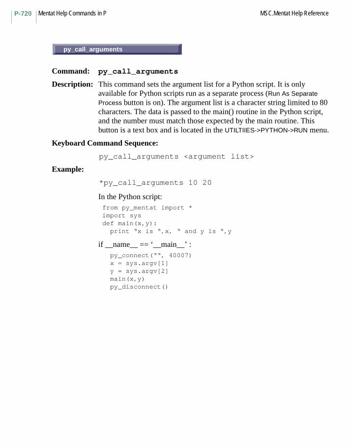
Mentat Help Commands in P MSC.Mentat Help ReferenceP-720
py_call_arguments
Command: py_call_arguments
Description: This command sets the argument list for a Python script. It is only available for Python scripts run as a separate process (Run As Separate Process button is on). The argument list is a character string limited to 80 characters. The data is passed to the main() routine in the Python script, and the number must match those expected by the main routine. This button is a text box and is located in the UTILTIIES->PYTHON->RUN menu.
Keyboard Command Sequence:
py_call_arguments <argument list>
Example:
*py_call_arguments 10 20
In the Python script: from py_mentat import * import sys def main(x,y): print “x is “,x, “ and y is “,y
if __name__ == ‘__main__’ : py_connect(““, 40007) x = sys.argv[1] y = sys.argv[2] main(x,y) py_disconnect()
py_call_arguments

P-721MSC.Mentat Help Reference Mentat Help Commands in P
BUILD
Command: py_call_module
Description: This command calls a named module in a Python script.
When the script is run, Mentat will initiate a socket connection if the RUN AS SEPARATE PROCESS button is on. It uses the current port number setting, which is set with the py_port command. Mentat will wait until it has established a connection with the separate Python process, however, it will still be active (commands may be issued and buttons may be pressed). The Python script must complete the connection with a call to the PyMentat method py_connect. When the Python script completes, it should call the PyMentat method py_disconnect.
If the RUN AS SEPARATE PROCESS button is not on, then the script will be run as an embedded script, meaning that Mentat will not be active until the script runs to completion (similar to executing a Mentat procedure file). No socket connection is initiated.
Keyboard Command Sequence:
py_call_module <python script name> <module name>
py_command
Command: py_command
Description: This command will run a Python command. The command must be given as a quoted string.
Keyboard Command Sequence:
py_command <command>
Example: py_command “R=7; a=5; print R+a”
BUILD
py_command

Mentat Help Commands in P MSC.Mentat Help ReferenceP-722
INITIATE CONNECTION
Command: py_connect
Description: This command will initiate a connection to an external Python process using the port number specified with the py_port command. When the command is issued, it will print the port number to which it is attempting to make the connection. If the connection has been initiated successfully, the “Wait connect” message will appear in the Status window. This button is located in the UTILTIIES->PYTHON menu.
A Python script will subsequently call the PyMentat method py_connect() to complete the connection, such as:
py_connect(“myhost.mydomain.com”,40007)
Keyboard Command Sequence:
py_connect
CLOSE CONNECTION
Command: py_disconnect
Description: This command will terminate a waiting connection to an external Python process using the port number specified with the py_port command. This button is located in the UTILTIIES->PYTHON menu.
This command may be issued from the command prompt, however, the PyMentat method py_disconnect() should be used instead in the Python script.
Keyboard Command Sequence:
py_disconnect
PyMentat Usage:
py_disconnect()
INITIATE CONNECTION
CLOSE CONNECTION

P-723MSC.Mentat Help Reference Mentat Help Commands in P
SCRIPT ECHO
Command: py_echo
Description: This command will enable or disable the echoing of Mentat commands in the dialogue window when a Python script is executed. This button is located in the UTILTIIES->PYTHON menu.
Keyboard Command Sequence:
py_echo <on or off>
PyMentat Example Usage:
py_send("*py_echo off")
RUN
Command: py_file_run
Description: This command will execute a Python script. There must be a module (method/function) named "main" defined in the script. That module will be invoked. This button is located in the UTILTIIES->PYTHON menu.
When the script is run, Mentat will initiate a socket connection if the RUN AS SEPARATE PROCESS button is on. It will use the current port number setting, which can be set with the py_port command. Mentat will wait until it has established a connection with the separate Python process, however, it will still be active (commands may be issued and buttons may be pressed). The Python script must complete the connection with a call to the PyMentat method py_connect. When the Python script completes, it should call the PyMentat method py_disconnect(). You should not exit Mentat until the Python script has completed, as this will cause the port to be remain "in use".
If the RUN AS SEPARATE PROCESS button is not on, then the script will be run as an embedded script, meaning that Mentat will not be active until the script runs to completion (similar to executing a Mentat procedure file). No socket connection is initiated.
Keyboard Command Sequence:
py_file_run <python script name>
SCRIPT ECHO
RUN
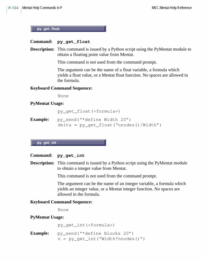
Mentat Help Commands in P MSC.Mentat Help ReferenceP-724
py_get_float
Command: py_get_float
Description: This command is issued by a Python script using the PyMentat module to obtain a floating point value from Mentat.
This command is not used from the command prompt.
The argument can be the name of a float variable, a formula which yields a float value, or a Mentat float function. No spaces are allowed in the formula.
Keyboard Command Sequence:
None
PyMentat Usage:
py_get_float(<formula>)
Example: py_send(“*define Width 20”)delta = py_get_float(“nnodes()/Width”)
py_get_int
Command: py_get_int
Description: This command is issued by a Python script using the PyMentat module to obtain a integer value from Mentat.
This command is not used from the command prompt.
The argument can be the name of an integer variable, a formula which yields an integer value, or a Mentat integer function. No spaces are allowed in the formula.
Keyboard Command Sequence:
None
PyMentat Usage:
py_get_int(<formula>)
Example: py_send(“*define Blocks 20”)n = py_get_int(“Width*nnodes()”)
py_get_float
py_get_int
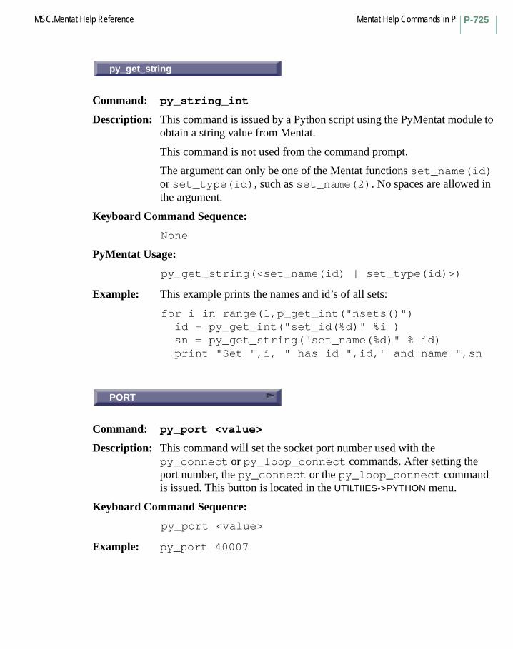
P-725MSC.Mentat Help Reference Mentat Help Commands in P
py_get_string
Command: py_string_int
Description: This command is issued by a Python script using the PyMentat module to obtain a string value from Mentat.
This command is not used from the command prompt.
The argument can only be one of the Mentat functions set_name(id) or set_type(id), such as set_name(2). No spaces are allowed in the argument.
Keyboard Command Sequence:
None
PyMentat Usage:
py_get_string(<set_name(id) | set_type(id)>)
Example: This example prints the names and id’s of all sets:
for i in range(1,p_get_int("nsets()") id = py_get_int("set_id(%d)" %i ) sn = py_get_string("set_name(%d)" % id) print "Set ",i, " has id ",id," and name ",sn
PORT
Command: py_port <value>
Description: This command will set the socket port number used with the py_connect or py_loop_connect commands. After setting the port number, the py_connect or the py_loop_connect command is issued. This button is located in the UTILTIIES->PYTHON menu.
Keyboard Command Sequence:
py_port <value>
Example: py_port 40007
py_get_string
PORT

Mentat Help Commands in P MSC.Mentat Help ReferenceP-726
py_prompt
Command: py_prompt
Description: This command is issued by a Python script using the PyMentat module py_prompt() to display the message at the command prompt. It is typically used inside of a Python script to send a status message to the user.
This command is not used from the command prompt.
Keyboard Command Sequence: py_prompt <string>
PyMentat Usage:str = "Creating Nodes"py_send("*py_prompt " + str)
RESET
Command: py_reset
Description: This command will terminate the Python interpreter. It should be called when a Python error occurs.
Keyboard Command Sequence: py_reset
RUN AS SEPARATE PROCESS
Command: py_separate_process
Description: This command will enable or disable running a Python script in a separate process. It allows a Python script to run outside of Mentat and thus allowing the graphics to be updated as the script proceeds. This button is located in the UTILTIIES->PYTHON->RUN menu.
Note: This option may not be turned on for the IBM platforms.
Keyboard Command Sequence: py_separate_process <on or off>
py_prompt
RESET
RUN AS SEPARATE PROCESS

Mentat Help Commands in QEXIT
Command: quit
Description: This command terminates a Mentat session.
Keyboard Command Sequence:
quit <‘y'or'n'>
Q Commands Begin with Q
EXIT

Mentat Help Commands in Q MSC.Mentat Help ReferenceQ-728

Mentat Help Commands in RLIMITS
Command: range
Description: This command sets the highest and lowest values displayed in contour plots. This range is used if automatic range calculation is turned off. The range is set to the current increment’s min and max values if the COPY LIMITS button (copy_autorange command) is selected.
Also see help: set_autorange and copy_autorange.
Keyboard Command Sequence: range <lowest value> <highest value>
NAME
Command: rbe2_name
Description: This command sets the name for the current rbe2.
Keyboard Command Sequence: rbe2_name <name>
R Commands Begin with R
LIMITS
NAME

Mentat Help Commands in R MSC.Mentat Help ReferenceR-730
NODE
Command: rbe3_ret_node
Description: This command sets the id of the retained (reference) node for the current rbe2.
Keyboard Command Sequence:
rbe2_ret_node <node_id>
DOF
Command: rbe2_tied_dof
Description: This command sets the dof of the retained (reference) node for the current rbe2.
Keyboard Command Sequence:
rbe2_tied_dof <dof_id>
COEF.
Command: rbe3_ret_coef
Description: This command sets the coef of the retained node for the current rbe3.
Keyboard Command Sequence:
rbe3_ret_coef <slot_id> <coef>
DOF
Command: rbe3_ret_dof
Description: This command sets the dof of the retained node for the current rbe3.
Keyboard Command Sequence:
rbe3_ret_dof <dof_id>
NODE
DOF
COEF.
DOF
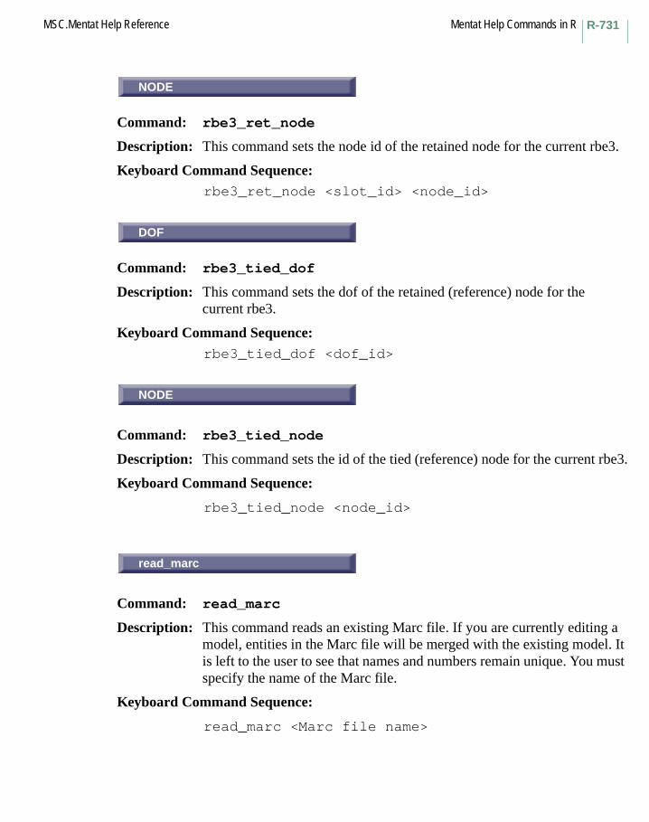
R-731MSC.Mentat Help Reference Mentat Help Commands in R
NODE
Command: rbe3_ret_node
Description: This command sets the node id of the retained node for the current rbe3.
Keyboard Command Sequence: rbe3_ret_node <slot_id> <node_id>
DOF
Command: rbe3_tied_dof
Description: This command sets the dof of the retained (reference) node for the current rbe3.
Keyboard Command Sequence: rbe3_tied_dof <dof_id>
NODE
Command: rbe3_tied_node
Description: This command sets the id of the tied (reference) node for the current rbe3.
Keyboard Command Sequence:
rbe3_tied_node <node_id>
read_marc
Command: read_marc
Description: This command reads an existing Marc file. If you are currently editing a model, entities in the Marc file will be merged with the existing model. It is left to the user to see that names and numbers remain unique. You must specify the name of the Marc file.
Keyboard Command Sequence:
read_marc <Marc file name>
NODE
DOF
NODE
read_marc
Mentat Help Commands in R MSC.Mentat Help ReferenceR-732
REBAR
Subroutine: REBAR
Description: The user subroutine REBAR allows the input of the position, size, and orientation of the single strain rebar elements (23, 46, 47, 48).
REDRAW
Command: redraw
Description: This command redraws the current model. Only the information contained in the display list is redrawn, not any information that may require regeneration of the model to be seen (see the REGENERATE command).
Keyboard Command Sequence: redraw
REFINE
Command: refine_node
Description: This command subdivides elements about a node. The subdivision is such that only edges and faces adjacent to the node are modified, which preserves mesh continuity.
Keyboard Command Sequence: refine_node <node> <element list> #
REGEN
Command: regenerate
Description: This command instructs the program to traverse its database of geometric and mesh entities, in order to regenerate the graphics display lists with those entities, using the current plotting settings. The new display lists are then drawn, bringing the graphical appearance of the program up-to-date.
Keyboard Command Sequence: regenerate
REBAR
REDRAW
REFINE
REGEN
R-733MSC.Mentat Help Reference Mentat Help Commands in R
RELAX
Menu: RELAX
Description: This menu contains commands for modifying the mesh by repositioning nodes. Nodes are moved to reduce the amount of or distortion in the mesh.
NODES
Command: relax_nodes
Description: This command smoothes the mesh by adjusting the coordinates of the specified nodes. After completion, the coordinate of each node moved is the average of its neighbors’ coordinates.
Keyboard Command Sequence: relax_nodes <node list> #
NONE
Command: relax_none_fixed
Description: This command specifies that all nodes given to the relax_nodes command will be relaxed.
Keyboard Command Sequence: relax_none_fixed
OUTLINE
Command: relax_outline_fixed
Description: This command specifies that all nodes on the outline of the mesh will be excluded from the list given to the relax_nodes command and will therefore be unchanged.
Keyboard Command Sequence: relax_outline_fixed
RELAX
NODES
NONE
OUTLINE

Mentat Help Commands in R MSC.Mentat Help ReferenceR-734
RESET
Command: relax_reset
Description: This command resets the relaxation parameters to their default settings.
Keyboard Command Sequence: relax_reset
SURFACE
Command: relax_surface_fixed
Description: This command specifies that all nodes on the surface of the mesh will be excluded from the list given to the relax_nodes command and will therefore remain unchanged.
Keyboard Command Sequence:
relax_surface_fixed
relax_tolerance
Command: relax_tolerance
Description: This command sets the relaxation tolerance. The tolerance is used to terminate the relaxation iteration process and specifies the greatest node movement allowed (sum of the squares) before termination of the process. A limit of ten iterations is imposed.
Keyboard Command Sequence: relax_tolerance <tolerance>
MESH ADAPTIVITY
Menu: MESH ADAPTIVITY
Description: This menu contains the commands for specifying the criteria for global remeshing and local adaptivity.
Global remeshing allows different parts of the model to be remeshed. A new mesh is automatically created, relevant solution quantities are transferred to the new mesh and the analysis continues.
RESET
SURFACE
relax_tolerance
MESH ADAPTIVITY
R-735MSC.Mentat Help Reference Mentat Help Commands in R
Local adaptivity provides the capability to increase the number of elements and nodes to improve the accuracy of the solution. The capability is applicable for both linear elastic analysis and for nonlinear analysis. The capability can be used for lower-order elements, 3-node triangular, 4-node quadrilateral, 4-node tetrahedral, and 8-node hexahedral elements.
REM
Command: remove_adapt_elements
Description: This command removes elements from the current adapt. The elements in the list will no longer be adaptively meshed during the analysis according to the parameters in this adapt. This button is located in the MESH ADAPTIVITY->LOCAL ADAPTIVITY menu.
Keyboard Command Sequence: remove_adapt_elements <element list> #
REMOVE ALL BOUND CONDS
Command: remove_all_applys
Description: This command deletes all boundary conditions.
Keyboard Command Sequence: remove_all_applys
REMOVE ALL CAVITIES
Command: remove_all_cavities
Description: This command removes all cavities from the model. It is located under the MESH GENERATION->CAVITIES (CURVES) menu.
Keyboard Command Sequence:
remove_all_cavities
REM
REMOVE ALL BOUND CONDS
REMOVE ALL CAVITIES
Mentat Help Commands in R MSC.Mentat Help ReferenceR-736
REMOVE ALL INITIAL CONDS
Command: remove_all_iconds
Description: This command deletes all initial conditions.
Keyboard Command Sequence: remove_all_iconds
REMOVE ALL RBE2’S
Command: remove_all_rbe2s
Description: This command removes all existing RBE2’s.
Keyboard Command Sequence:
remove_all_rbe2s
REMOVE ALL RBE’S
Command: remove_all_rbe3s
Description: This command removes all existing RBE3’s.
Keyboard Command Sequence:
remove_all_rbe3s
REM ALL SERVOS
Command: remove_all_servos
Description: This command deletes all servo links.
Keyboard Command Sequence: remove_all_servos
REMOVE ALL INITIAL CONDS
REMOVE ALL RBE2’S
REMOVE ALL RBE3’S
REM ALL SERVOS

R-737MSC.Mentat Help Reference Mentat Help Commands in R
REMOVE ALL SETS
Command: remove_all_sets
Description: This command removes all sets from the model.
Keyboard Command Sequence: remove_all_sets
REM ALL SPRINGS
Command: remove_all_springs
Description: This command deletes all servo links.
Keyboard Command Sequence: remove_all_springs
REM ALL TIES
Command: remove_all_ties
Description: This command deletes all ties.
Keyboard Command Sequence: remove_all_ties
REMOVE
Command: remove_annotation
Description: This command is used to remove annotations from a view. Annotations are strings of text that can be used to describe what is being displayed in a view. You must specify a list of annotations to remove. This button is located in the UTILITIES->MORE menu.
Keyboard Command Sequence: remove_annotation <annotation list> #
REMOVE ALL SETS
REM ALL SPRINGS
REM ALL TIES
REMOVE

Mentat Help Commands in R MSC.Mentat Help ReferenceR-738
REM
Command: remove_apply_cavities
Description: This command removes cavities from the current boundary condition cavity pressure/mass load. This button is located in the BOUNDARY CONDITIONS->MECHANICAL->CAVITY PRESSURE/MASS LOAD menus.
Keyboard Command Sequence:
remove_apply_cavities <cavity list> #
REM
Command: remove_apply_curves
Description: This command removes curves from the current boundary condition application. You must specify a list of curves. This button is located in the BOUNDARY CONDITIONS->MECHANICAL->FIXED DISPLACEMENT and other boundary condition class menus.
Keyboard Command Sequence:
remove_apply_curves <curve list> #
REM
Command: remove_apply_edges
Description: This command removes edges from the current boundary condition application. You must specify a list of edges. This button is located in the BOUNDARY CONDITIONS->MECHANICAL->EDGE LOAD and other boundary condition class menus.
Keyboard Command Sequence:
remove_apply_edges <edge list> #
REM
REM
REM
R-739MSC.Mentat Help Reference Mentat Help Commands in R
REM
Command: remove_apply_elements
Description: This command removes elements from the current boundary condition application. You must specify a list of elements. This button is located in the BOUNDARY CONDITIONS->MECHANICAL->GLOBAL LOAD and other boundary condition class menus.
Keyboard Command Sequence: remove_apply_elements <element list> #
REM
Command: remove_apply_faces
Description: This command removes faces from the current boundary condition application. You must specify a list of faces. This button is located in the BOUNDARY CONDITIONS->MECHANICAL->FACE LOAD and other boundary condition class menus.
Keyboard Command Sequence: remove_apply_faces <face list> #
REM
Command: remove_apply_nodes
Description: This command removes nodes from the current boundary condition application. You must specify a list of nodes. This button is located in the BOUNDARY CONDITIONS->MECHANICAL->FIXED DISPLACEMENT and other boundary condition class menus.
Keyboard Command Sequence: remove_apply_nodes <node list> #
REM
Command: remove_apply_points
Description: This command removes points from the current boundary condition application. You must specify a list of points. This button is located in the
REM
REM
REM
REM
Mentat Help Commands in R MSC.Mentat Help ReferenceR-740
BOUNDARY CONDITIONS->MECHANICAL->FIXED DISPLACEMENT and other boundary condition class menus.
Keyboard Command Sequence:
remove_apply_points <point list> #
REM
Command: remove_apply_surfaces
Description: This command removes surfaces from the current boundary condition application. You must specify a list of surfaces. This button is located in the BOUNDARY CONDITIONS->MECHANICAL->FIXED DISPLACEMENT and other boundary condition class menus.
Keyboard Command Sequence: remove_apply_surfaces <surface list> #
REM
Command: remove_cavity_curves
Description: This command removes curves from the current cavity. It is located under the MESH GENERATION->CAVITIES (CURVES) menu.
Keyboard Command Sequence: remove_cavity_curves <curve list> #
REM
Command: remove_cavity_edges
Description: This command removes element edges from the current cavity. It is located under the MESH GENERATION->CAVITIES (EDGES) menu.
Keyboard Command Sequence: remove_cavity_edges <edge list> #
REM
REM
REM
R-741MSC.Mentat Help Reference Mentat Help Commands in R
REM
Command: remove_cavity_faces
Description: This command removes element faces from the current cavity. It is located under the MESH GENERATION->CAVITIES (FACES) menu.
Keyboard Command Sequence: remove_cavity_faces <face list> #
REM
Command: remove_cavity_surfaces
Description: This command removes surfaces from the current cavity. It is located under the MESH GENERATION->CAVITIES (SURFACES) menu.
Keyboard Command Sequence: remove_cavity_surfaces <surface list> #
REM
Command: remove_cbody_dc_edges
Description: This command removes edges from the list of edges defining discontinuities in the analytical formulation for deformable bodies. You must specify a list of edges. This button is located in the CONTACT-> CONTACT BODIES->DEFORMABLE and RIGID w HEAT TRANSFER menus with ANALYTIC option on.
Keyboard Command Sequence: remove_cbody_dc_edges <edge list> #
REM
Command: remove_cbody_dc_nodes
Description: This command removes nodes from the list of nodes defining discontinuities in the analytical formulation for deformable bodies. You must specify a list of nodes. This button is located in the CONTACT-> CONTACT BODIES->DEFORMABLE and RIGID w HEAT TRANSFER menus with ANALYTIC option on.
REM
REM
REM
REM
Mentat Help Commands in R MSC.Mentat Help ReferenceR-742
Keyboard Command Sequence: remove_cbody_dc_nodes <node list> #
REM
Command: remove_contact_body_curves
Description: This command removes curves from the current contact body. You must specify a list of curves. This button is located in the CONTACT->CONTACT BODIES->RIGID and SYMMETRY menus.
Keyboard Command Sequence: remove_contact_body_curves <curve list> #
REM
Command: remove_contact_body_elem
Description: This command removes elements from the current contact body. You must specify a list of elements. This button is located in the CONTACT->CONTACT BODIES->DEFORMABLE and other contact body type menus.
Keyboard Command Sequence: remove_contact_body_elem <element list> #
REM
Command: remove_contact_body_surf
Description: This command removes surfaces from the current contact body. You must specify a list of surfaces. This button is located in the CONTACT->CONTACT BODIES->RIGID and SYMMETRY menus.
Keyboard Command Sequence: remove_contact_body_surf <surface list> #
REM
REM
REM
R-743MSC.Mentat Help Reference Mentat Help Commands in R
REM
Command: remove_crack_rigreg_nodes
Description: This command removes nodes from the current rigid region of the current crack. This button is located in the FRACTURE MECHANICS->2-D CRACKS/3-D CRACKS->MANUAL menu.
Keyboard Command Sequence: remove_crack_rigreg_nodes <rigid region><node list> #
REM
Command: remove_csect_elements
Description: This command removes elements from the current cross-section. This button is located in the BOUNDARY CONDITIONS->MECHANICAL->CROSS SECTIONS menu.
Keyboard Command Sequence: remove_csect_elements <element list> #
REM
Command: remove_csect_nodes
Description: This command removes nodes from the current cross-section. This button is located in the BOUNDARY CONDITIONS->MECHANICAL->CROSS SECTIONS menu.
Keyboard Command Sequence: remove_csect_nodes <node list> #
REM
REM
REM

Mentat Help Commands in R MSC.Mentat Help ReferenceR-744
REM
Command: remove_current_adapg
Description: This command removes the current entry of remeshing criteria. Upon removal, the previous entry becomes the current one. If there is no previous entry, the next one will become the current one. This button is located in the MESH ADAPTIVITY->GLOBAL REMESHING menu.
Keyboard Command Sequence: remove_current_adapg
REM
Command: remove_current_adapt
Description: This command removes the current adapt. Upon removal, the previous adapt becomes the current one. If there is no previous adapt, the next one will become the current one. This button is located in the MESH ADAPTIVITY->LOCAL ADAPTIVITY menu.
Keyboard Command Sequence: remove_current_adapt
REM
Command: remove_current_apply
Description: This command removes the current boundary condition application. Upon removal, the previous application becomes the current one. If there is no previous application, the next one will become the current one. This button is located in the BOUNDARY CONDITIONS menu.
Keyboard Command Sequence: remove_current_apply
REM
REM
REM
R-745MSC.Mentat Help Reference Mentat Help Commands in R
REM
Command: remove_current_cavity
Description: This command removes the current cavity. Upon removal, the previous cavity becomes the current one. If there is no previous cavity, the next one will become the current one. It is located under the MESH GENERATION-> CAVITIES menu.
Keyboard Command Sequence: remove_current_cavity
REM
Command: remove_current_contact_area
Description: This command removes the current contact area. Upon removal, the previous contact area becomes the current one. If there is no previous contact area, the next one becomes the current one. This button is located in the CONTACT->CONTACT AREAS menu.
Keyboard Command Sequence: remove_current_contact_area
REM
Command: remove_current_contact_body
Description: This command removes the current contact body. Upon removal, the previous contact body becomes the current one. If there is no previous contact body, the next one becomes the current one. This button is located in the CONTACT->CONTACT BODIES menu.
Keyboard Command Sequence: remove_current_contact_body
REM
REM
REM
Mentat Help Commands in R MSC.Mentat Help ReferenceR-746
REM
Command: remove_current_contact_table
Description: This command removes the current contact table. Upon removal, the previous contact table becomes the current one. If there is no previous contact table, the next one becomes the current one. This button is located in the CONTACT->CONTACT TABLES menu.
Keyboard Command Sequence: remove_current_contact_table
REM
Command: remove_current_crack
Description: This command removes the current crack. Upon removal, the previous crack becomes the current one. If there is no previous crack, the next one will become the current one.
Keyboard Command Sequence: remove_current_crack
REM
Command: remove_current_csect
Description: This command removes the current cross-section. Upon removal, the previous cross-section becomes the current one. If there is no previous cross-section, the next one will become the current one. This button is located in the BOUNDARY CONDITIONS->MECHANICAL->CROSS SECTIONS menu.
Keyboard Command Sequence: remove_current_csect
REM
REM
REM
R-747MSC.Mentat Help Reference Mentat Help Commands in R
REM
Command: remove_current_descon
Description: This command removes the current design constraint. Upon removal, the previous design constraint becomes the current one. If there is no previous design constraint, the next one will become the current one. This button is located in the DESIGN->DESIGN CONSTRAINTS menu.
Keyboard Command Sequence:
remove_current_descon
REM
Command: remove_current_desvar
Description: This command removes the current design variable. Upon removal, the previous design variable becomes the current one. If there is no previous design variable, the next one will become the current one. This button is located in the DESIGN->DESIGN VARIABLES menu.
Keyboard Command Sequence:
remove_current_desvar
REM
Command: remove_current_exseg
Description: This command removes the current exclude segment. Upon removal, the previous exclude segment becomes the current one. If there is no previous exclude segment, the next one becomes the current one. This button is located in the CONTACT->EXCLUDE SEGMENTS menu.
Description:
Keyboard Command Sequence:
remove_current_exseg
REM
REM
REM

Mentat Help Commands in R MSC.Mentat Help ReferenceR-748
REM
Command: remove_current_geometry
Description: This command removes the current geometry property. Upon removal, the previous geometry becomes the current one. If there is no previous geometry property, the next one will become the current one. This button is located in the GEOMETRIC PROPERTIES menu.
Keyboard Command Sequence:
remove_current_geometry
REM
Command: remove_current_icond
Description: This command removes the current initial condition. Upon removal, the previous initial condition becomes the current one. If there is no previous initial condition, the next one will become the current one. This button is located in the INITIAL CONDITIONS menu.
Keyboard Command Sequence:
remove_current_icond
REM
Command: remove_current_insert
Description: This command removes the current insert. Upon removal, the previous insert becomes the current one. If there is no previous insert, the next one will become the current one.
Keyboard Command Sequence:
remove_current_insert
REM
REM
REM

R-749MSC.Mentat Help Reference Mentat Help Commands in R
REM
Command: remove_current_job
Description: This command removes the current job. Upon removal, the previous job becomes the current one. If there is no previous job, the next one will become the current one. This button is located in the JOBS menu.
Keyboard Command Sequence:
remove_current_job
REM
Command: remove_current_link
Description: This command removes the current link. Upon removal, the previous link becomes the current one. If there is no previous boundary condition, the next one will become the current one. This button is located in the LINKS->NODAL TIES, SERVO LINKS, and SPRINGS/DASHPOTS menus.
Keyboard Command Sequence:
remove_current_link
REM
Command: remove_current_loadcase
Description: This command removes the current loadcase. Upon removal, the previous loadcase becomes the current one. If there is no previous loadcase, the next one will become the current one. This button is located in the LOADCASES menu.
Keyboard Command Sequence:
remove_current_loadcase
REM
REM
REM

Mentat Help Commands in R MSC.Mentat Help ReferenceR-750
REM
Command: remove_current_material
Description: This command removes the current material. Upon removal, the previous material becomes the current one. If there is no previous material, the next one will become the current one. This button is located in the MATERIAL PROPERTIES menu.
Keyboard Command Sequence:
remove_current_material
NEW
Command: remove_current_rbe2
Description: This command the current rbe2. Upon removal, the previous rbe2 becomes the current one. If there is no previous rbe2, the next one will become the current one.This button is located in the LINKS->RBE2’S menu.
Keyboard Command Sequence:
remove_current_rbe2
NEW
Command: remove_current_rbe3
Description: This command the current rbe3. Upon removal, the previous rbe3 becomes the current one. If there is no previous rbe3, the next one will become the current one.This button is located in the LINKS->RBE3’S menu.
Keyboard Command Sequence:
remove_current_rbe3
REM
NEW
NEW
R-751MSC.Mentat Help Reference Mentat Help Commands in R
REM
Command: remove_current_section
Description: This command removes the current beam section. Upon removal, the previous section becomes the current one. If there is no previous section, the next one will become the current one. This button is located in the GEOMETRIC PROPERTIES->MECHANICAL->BEAM SECTIONS menu.
Keyboard Command Sequence:
remove_current_section
REM
Command: remove_current_table
Description: This command removes the current tables. Upon removal, the previous table becomes the current one. If there is no previous table, the next one will become the current one. This button is located in the MATERIAL PROPERTIES->TABLES or any other link to the TABLES menu.
Keyboard Command Sequence:
remove_current_table
CURVE
Command: remove_curve_sets
Description: This command removes all curve sets from the model. This button is located in the MESH GENERATION->SELECT->REMOVE SETS or any other link to the SELECT menu.
Keyboard Command Sequence:
remove_curve_sets
REM
REM
CURVE

Mentat Help Commands in R MSC.Mentat Help ReferenceR-752
REM
Command: remove_curves
Description: This command removes curves from the model. You must specify a list of curves. This button is located in the MESH GENERATION menu.
Keyboard Command Sequence: remove_curves <curve list> #
EDGE
Command: remove_edge_sets
Description: This command removes all edge sets from the model. This button is located in the MESH GENERATION->SELECT->REMOVE SETS or any other link to the SELECT menu.
Keyboard Command Sequence: remove_edge_sets
ELEMENT
Command: remove_element_sets
Description: This command removes all element sets from the model. This button is located in the MESH GENERATION->SELECT->REMOVE SETS or any other link to the SELECT menu.
Keyboard Command Sequence: remove_element_sets
REM
Command: remove_elements
Description: This command removes elements from the model. You must specify a list of elements. This button is located in the MESH GENERATION menu.
Keyboard Command Sequence: remove_elements <element list> #
REM
EDGE
ELEMENT
REM

R-753MSC.Mentat Help Reference Mentat Help Commands in R
REMOVE EMPTY SETS
Command: remove_empty_sets
Description: This command removes all empty sets from the model. This button is located in the MESH GENERATION->SELECT->REMOVE SETS or any other link to the SELECT menu.
Keyboard Command Sequence:
remove_empty_sets
FACE
Command: remove_face_sets
Description: This command removes all face sets from the model. This button is located in the MESH GENERATION->SELECT->REMOVE SETS or any other link to the SELECT menu.
Keyboard Command Sequence:
remove_face_sets
REM
Command: remove_geometry_elements
Description: This command removes elements from the current geometry property. You must specify a list of elements. This button is located in the GEOMETRIC PROPERTIES->3D and other geometric properties menus.
Keyboard Command Sequence:
remove_geometry_elements <element list> #
REMOVE EMPTY SETS
FACE
REM

Mentat Help Commands in R MSC.Mentat Help ReferenceR-754
REM
Command: remove_icond_curves
Description: This command removes curves from the current initial condition. You must specify a list of curves. This button is located in the INITIAL CONDITIONS->MECHANICAL and other initial conditions menus.
Keyboard Command Sequence:
remove_icond_curves <curve list> #
REM
Command: remove_icond_edges
Description: This command removes edges from the current initial condition. You must specify a list of edges. This button is located in the INITIAL CONDITIONS->MECHANICAL and other initial conditions menus.
Keyboard Command Sequence:
remove_icond_edges <edge list> #
REM
Command: remove_icond_elements
Description: This command removes elements from the current initial condition. You must specify a list of elements. This button is located in the INITIAL CONDITIONS->MECHANICAL and other initial conditions menus.
Keyboard Command Sequence:
remove_icond_elements <element list> #
REM
REM
REM
R-755MSC.Mentat Help Reference Mentat Help Commands in R
REM
Command: remove_icond_faces
Description: This command removes faces from the current initial condition. You must specify a list of faces. This button is located in the INITIAL CONDITIONS->MECHANICAL and other initial conditions menus.
Keyboard Command Sequence:
remove_icond_faces <face list> #
REM
Command: remove_icond_nodes
Description: This command removes nodes from the current initial condition. You must specify a list of nodes. This button is located in the INITIAL CONDITIONS->MECHANICAL and other initial conditions menus.
Keyboard Command Sequence:
remove_icond_nodes <node list> #
REM
Command: remove_icond_points
Description: This command removes points from the current initial condition. You must specify a list of points. This button is located in the INITIAL CONDITIONS->MECHANICAL and other initial conditions menus.
Keyboard Command Sequence:
remove_icond_points <point list> #
REM
REM
REM
Mentat Help Commands in R MSC.Mentat Help ReferenceR-756
REM
Command: remove_icond_surfaces
Description: This command removes surfaces from the current initial condition. You must specify a list of surfaces. This button is located in the INITIAL CONDITIONS->MECHANICAL and other initial conditions menus.
Keyboard Command Sequence:
remove_icond_surfaces <surface list> #
stress
Command: remove_ideas_elem_var
Description: This command removes results ideas variables from the list of requested variables for the current job. You must specify a variable by name. The button text will be the name of the results variable. This button is located in the JOBS->MECHANICAL->JOB RESULTS->I-DEAS and other analysis class menus.
Keyboard Command Sequence:
remove_ideas_elem_var <variable name>
stress
Command: remove_ideas_elnod_var
Description: This command removes results ideas variables from the list of requested variables for the current job. You must specify a variable by name. The button text will be the name of the results variable. This button is located in the JOBS->MECHANICAL->JOB RESULTS->I-DEAS and other analysis class menus.
Keyboard Command Sequence:
remove_ideas_elnod_var <variable name>
REM
stress
stress
R-757MSC.Mentat Help Reference Mentat Help Commands in R
displacement
Command: remove_ideas_node_var
Description: This command removes results ideas variables from the list of requested variables for the current job. You must specify a variable by name. The button text will be the name of the results variable. This button is located in the JOBS->MECHANICAL->JOB RESULTS->I-DEAS and other analysis class menus.
Keyboard Command Sequence:
remove_ideas_node_var <variable name>
REM
Command: remove_insert_embedded
Description: This command removes embedded elements or embedded nodes from current insert.
Keyboard Command Sequence:
remove_insert_embedded <elements list> or<nodes list>
REM
Command: remove_insert_host_elements
Description: This command removes host elements from current insert.
Keyboard Command Sequence:
remove_insert_host_elements <elements list>
displacement
REM
REM
Mentat Help Commands in R MSC.Mentat Help ReferenceR-758
apply1
Command: remove_job_applys
Description: This command removes initial load applications from the current job. Load applications are specified by name. The button text will be the name of the initial condition. This button is located in the JOBS-> MECHANICAL->INITIAL LOADS and other analysis class menus.
Keyboard Command Sequence:
remove_job_applys <load apply name>
carea1
Command: remove_job_careas
Description: This command removes contact areas from the current job. The specified contact areas will no longer be used as initial contact areas for the job. Contact areas are specified by name. The button text will be the name of the contact area. This button is located in the JOBS->MECHANICAL-> CONTACT CONTROL->INITIAL CONTACT and other analysis class menus.
Keyboard Command Sequence:
remove_job_careas <contact area names>
icond1
Command: remove_job_iconds
Description: This command removes initial conditions from the current job. The specified conditions will no longer be used as initial load conditions for the job. Initial conditions are specified by name. The text on the button will be the name of the initial condition. This button is located in the JOBS->MECHANICAL->INITIAL LOADS and other analysis class menus.
Keyboard Command Sequence:
remove_job_iconds <initial condition names>
apply1
carea1
icond1

R-759MSC.Mentat Help Reference Mentat Help Commands in R
lcase1
Command: remove_job_loadcases
Description: This command removes loadcases from the current job. Loadcases are specified by name. The button text will be the name of the loadcase. This button is located in the JOBS->MECHANICAL->AVAILABLE and other analysis class menus.
Keyboard Command Sequence: remove_job_loadcases <loadcase name>
carea1
Command: remove_loadcase_careas
Description: This command deactivates contact areas in the current loadcase. Only activated contact areas are considered during analysis. Contact areas are specified by name. The button text will be the name of the contact area. This button is located in the LOADCASES->MECHANICAL->STATIC-> CONTACT->CONTACT AREAS and other loadcase class menus.
Keyboard Command Sequence: remove_loadcase_careas <contact area names>
cbody1
Command: remove_loadcase_cbodies
Description: This command allows adhesion between the specified contact bodies and all other contact bodies for the current loadcase. Releasing a contact body (see add_loadcase_cbodies) during an analysis forces a separation between that body and any other body touching it. The button text will be the name of the contact area. This button is located in the LOADCASES-> MECHANICAL->STATIC->CONTACT->CONTACT AREAS and other loadcase class menus.
Keyboard Command Sequence: remove_loadcase_cbodies <contact body names>
lcase1
carea1
cbody1
Mentat Help Commands in R MSC.Mentat Help ReferenceR-760
apply1
Command: remove_loadcase_loads
Description: This command deactivates boundary conditions applications (loads) in the current loadcase. Deactivated applications are ignored during analysis. You must specify a boundary condition application name. The button text will be the name of the load. This button is located in the LOADCASES-> MECHANICAL->STATIC->LOADS and other loadcase class menus
Keyboard Command Sequence:
remove_loadcase_loads <application name>
REMOVE
Command: remove_marc_history_text
Description: This command allows removing a line that will be placed in the Marc data file at the end of the history definition section.
The command input consists of the line number that you want to remove.
Keyboard Command Sequence:
remove_marc_history_text <line number>
REMOVE
Command: remove_marc_model_text
Description: This command allows removing a line that will be placed in the Marc data file at the end of the model definition section.
The command input consists of the line number that you want to remove.
Keyboard Command Sequence:
remove_marc_model_text <line number>
apply1
REMOVE
REMOVE
R-761MSC.Mentat Help Reference Mentat Help Commands in R
REMOVE
Command: remove_marc_param_text
Description: This command allows removing a line that will be placed in the Marc data file at the end of the parameter definition section.
The command input consists of the line number that you want to remove.
Keyboard Command Sequence:
remove_marc_param_text <line number>
REM
Command: remove_material_elements
Description: This command removes elements from the current material. This has the effect of removing the material from the elements. You must specify a list of elements. This button is located in the MATERIAL PROPERTIES menu.
Keyboard Command Sequence:
remove_material_elements <element list> #
NODE
Command: remove_node_sets
Description: This command removes all node sets from the model. This button is located in the MESH GENERATION->SELECT->REMOVE SETS or any other link to the SELECT menu.
Keyboard Command Sequence:
remove_node_sets
REMOVE
REM
NODE
Mentat Help Commands in R MSC.Mentat Help ReferenceR-762
REM
Command: remove_nodes
Description: This command removes nodes from the model. You must specify a list of nodes. Only the nodes which are not used by any element will be removed. This button is located in the MESH GENERATION menu.
Keyboard Command Sequence:
remove_nodes <node list> #
REM
Command: remove_normal_edges
Description: This command is used to specify which element edges contribute to the computation of node normals used in post plotting. This button is located in the RESULTS->TOOLS menu.
Keyboard Command Sequence:
remove_normal_edges <element edge list>
REM
Command: remove_normal_faces
Description: This command is used to specify which element faces contribute to the computation of node normals used in post plotting. This button is located in the RESULTS->TOOLS menu.
Keyboard Command Sequence:
remove_normal_faces <element face list>
REM
REM
REM
R-763MSC.Mentat Help Reference Mentat Help Commands in R
REM
Command: remove_orient
Description: This command removes the current orientation. Upon removal, the previous orientation becomes the current one. If there is no previous orientation, the next one will become the current one. This button is located in the MATERIAL PROPERTIES->ORIENTATIONS menu.
Keyboard Command Sequence:
remove_orient
REM
Command: remove_orient_elements
Description: This command removes the current orientation from the specified elements. This button is located in the MATERIAL PROPERTIES-> ORIENTATIONS menu.
Keyboard Command Sequence:
remove_orient_elements <elements list> #
POINT
Command: remove_point_sets
Description: This command removes all point sets from the model. This button is located in the MESH GENERATION->SELECT->REMOVE SETS or any other link to the SELECT menu.
Keyboard Command Sequence:
remove_point_sets
REM
REM
POINT
Mentat Help Commands in R MSC.Mentat Help ReferenceR-764
REM
Command: remove_points
Description: This command removes points from the model. You must specify a list of points. Only those points not used by any curve or surface will be removed. This button is located in the MESH GENERATION menu.
Keyboard Command Sequence:
remove_points <point list> #
Stress
Command: remove_post_tensor
Description: This command removes results tensors from the list of requested tensors for the current job. You must specify a tensor name. The button text will be the name of the element tensor. This button is located in the JOBS-> MECHANICAL->JOB RESULTS and other analysis class menus.
Keyboard Command Sequence:
remove_post_tensor <tensor name>
Equivalent Von Mises
Command: remove_post_var
Description: This command removes results variables from the list of requested variables for the current job. You must specify a variable name. The button text will be the name of the element variable. This button is located in the JOBS->MECHANICAL->JOB RESULTS and other analysis class menus.
Keyboard Command Sequence:
remove_post_var <variable name>
REM
Stress
Equivalent Von Mises
R-765MSC.Mentat Help Reference Mentat Help Commands in R
REM
Command: remove_rbe2_tied_nodes
Description: This command removes tied nodes by list of node id’s. This button is located in the LINKS->RBE2’S menu.
The nodes are entered directly on the command line, by picking them with the mouse.
Keyboard Command Sequence:
remove_rbe2_tied_nodes <node list> #
REM
Command: remove_rbe3_ret_nodes
Description: This command removes retained nodes by list of node id’s. This button is located in the LINKS->RBE3’S menu.
The nodes are entered directly on the command line, by picking them with the mouse.
Keyboard Command Sequence:
remove_rbe3_ret_nodes <node list> #
DEL ENTRIES
Command: remove_set_entries
Description: This command removes entries from the specified set. The type of entries specified in the list must correspond to the type of set; e.g. a list of nodes should be given for a node set. This command is used for types of sets for which there is a store command (as in store_nodes, store_elements, etc). This button is located in the MESH GENERATION->SELECT or any other link to the SELECT menu.
Keyboard Command Sequence:
remove_set_entries <set name> <entry list> #
REM
REM
DEL ENTRIES

Mentat Help Commands in R MSC.Mentat Help ReferenceR-766
REMOVE ONE SET
Command: remove_sets
Description: This command removes stored sets. You must specify a list of sets. This button is located in the MESH GENERATION->SELECT->REMOVE SETS or any other link to the SELECT menu.
Keyboard Command Sequence:
remove_sets <set list> #
SOLID EDGE
Command: remove_solid_edge_sets
Description: This command removes all solid edge sets from the model. This button is located in the MESH GENERATION->SELECT->REMOVE SETS or any other link to the SELECT menu.
remove_solid_edge_sets
SOLID FACE
Command: remove_solid_face_sets
Description: This command removes all solid face sets from the model. This button is located in the MESH GENERATION->SELECT->REMOVE SETS or any other link to the SELECT menu.
Keyboard Command Sequence:
remove_solid_face_sets
REMOVE ONE SET
SOLID EDGE
SOLID FACE
R-767MSC.Mentat Help Reference Mentat Help Commands in R
SOLID
Command: remove_solid_sets
Description: This command removes all solid sets from the model. This button is located in the MESH GENERATION->SELECT->REMOVE SETS or any other link to the SELECT menu.
Keyboard Command Sequence: remove_solid_sets
SOLID VERTEX
Command: remove_solid_vertex_sets
Description: This command removes all solid vertex sets from the model. This button is located in the MESH GENERATION->SELECT->REMOVE SETS or any other link to the SELECT menu.
Keyboard Command Sequence: remove_solid_vertex_sets
REM
Command: remove_solids
Description: This command removes solids from the model. You must specify a list of solids. This button is located in the MESH GENERATION menu.
Keyboard Command Sequence: remove_solids <solid list> #
SURFACE
Command: remove_surface_sets
Description: This command removes all surface sets from the model. This button is located in the MESH GENERATION->SELECT->REMOVE SETS or any other link to the SELECT menu.
Keyboard Command Sequence:remove_surface_sets
SOLID
SOLID VERTEX
REM
SURFACE
Mentat Help Commands in R MSC.Mentat Help ReferenceR-768
REM
Command: remove_surfaces
Description: This command removes surfaces from the model. You must specify a list of surfaces. This button is located in the MESH GENERATION menu.
Keyboard Command Sequence:
remove_surfaces <surface list> #
REM
Command: remove_transform
Description: This command removes the current node transform. All nodes which were transformed by the transformation will no longer be transformed. After the transform is removed, the previous transform will become the current transform. If there is no previous transform, the next one will become the current one. A transform may not be deleted if nodes are still being transformed by it. This button is located in the BOUNDARY CONDITIONS->MECHANICAL->TRANSFORMS and other boundary conditions menus.
Keyboard Command Sequence:
remove_transform
REM
REM

R-769MSC.Mentat Help Reference Mentat Help Commands in R
REM
Command: remove_transform_nodes
Description: This command removes the specified nodes from the current transformation. This button is located in the BOUNDARY CONDITIONS-> MECHANICAL->TRANSFORMS and other boundary conditions menus.
Keyboard Command Sequence:
remove_transform_nodes <node list> #
NODES
Command: remove_unused_nodes
Description: This command removes from the model all nodes which are not being used by any element. This button is located in the MESH GENERATION-> SWEEP menu.
Keyboard Command Sequence:
remove_unused_nodes
REMOVE UNUSED
Command: remove_unused_orients
Description: This command removes all orientations that have not been applied to elements from the list of orientations. This button is located in the MATERIAL PROPERTIES->ORIENTATIONS menu.
Keyboard Command Sequence:
remove_unused_orients
REM
NODES
REMOVE UNUSED
Mentat Help Commands in R MSC.Mentat Help ReferenceR-770
POINTS
Command: remove_unused_points
Description: This command removes from the model all points which are not being used by any curve or surface. This button is located in the MESH GENERATION->SWEEP menu.
Keyboard Command Sequence:
remove_unused_points
REMOVE UNUSED
Command: remove_unused_transforms
Description: This command removes from the model all transforms which are not being used by any node. This button is located in the BOUNDARY CONDITIONS->MECHANICAL->TRANSFORMS and other boundary conditions menus.
Keyboard Command Sequence:
remove_unused_transforms
render
Command: render
Description: This command starts a rendering job in the background, which creates a photorealistic image of the 3-D geometry in a view. Mentat first writes out a render file with information for the render program. This file contains the current render settings, view settings, lighting settings, colormap information, and 3-D geometry. Then an external process is started, which reads in this file, and writes out the completed image file. When the image is complete, a new window displaying the image appears.
To remove the image window, move the mouse to the image window, and press "q" or the ESC key.
POINTS
REMOVE UNUSED
render

R-771MSC.Mentat Help Reference Mentat Help Commands in R
You must specify which view to render (1, 2, 3, or 4). A base file name must also be specified. Then, file name .ren will be the render file, and file name .rgb will be the image file.
Also see: image_display, image_slide, and image_save.
Keyboard Command Sequence:
render <view> <file name> <yes/no>
DEPTH
Command: render_antialias_depth
Description: This command allows you to specify the antialias depth for subsequent rendered images. Antialiasing is a technique which attempts to minimize the jaggedness and other unwanted artifacts that sometimes appear in raster images.
The Mentat renderer uses adaptive supersampling as its antialiasing technique. The exact color is computed at the four corners and center of each pixel. If any of these five colors differs from the average of the five by more than the antialias color tolerance, the pixel is divided into four sub-pixels, and the process is repeated for each sub-pixel, until the antialias depth has been reached. Thus the greater the depth is, the more times a pixel may be subdivided. A higher depth may make an image look better, while making it take longer to create.
You must specify the depth (one or greater).
Also see: render, render_antialias, and render_antialias_tol.
Keyboard Command Sequence:
render_antialias_depth <depth>
DEPTH

Mentat Help Commands in R MSC.Mentat Help ReferenceR-772
TOLERANCE
Command: render_antialias_tol
Description: This command allows you to specify the antialias color tolerance for subsequent rendered images. Antialiasing is a technique which attempts to minimize the jaggedness and other unwanted artifacts that sometimes appear in raster images.
The Mentat renderer uses adaptive supersampling as its antialiasing technique. The exact color is computed at the four corners and center of each pixel. If any of these five colors differs from the average of the five by more than the antialias color tolerance, the pixel is divided into four sub-pixels, and the process is repeated for each sub-pixel, until the antialias depth has been reached. Thus the smaller the tolerance is, the more likely a pixel will be subdivided. A lower tolerance may make an image look better, while making it take longer to create.
You must specify the color tolerance (0.0 to 1.0). A color tolerance of 0.0 forces all pixels to be subdivided up to the antialias depth.
Also see: render, render_antialias, and render_antialias_depth.
Keyboard Command Sequence: render_antialias_tol <tolerance>
COLOR
Command: render_atmosphere
Description: This command sets a colored atmosphere for subsequent rendered images. Thus, atmospheric depth cueing will be present. This means that the further away an object is, the more it will be obscured by the atmosphere color.
You must specify the red, green, and blue components of the color. These values range from zero to one, where zero means completely OFF, and one means completely ON. Setting the atmosphere color to black (0, 0, 0) turns off the atmosphere effect.
Also see: render, render_clear, render_fog, render_haze, render_smog, render_atmosphere_len, and render_atmosphere_index_ref.
TOLERANCE
COLOR

R-773MSC.Mentat Help Reference Mentat Help Commands in R
Keyboard Command Sequence: render_atmosphere <red> <green> <blue>
INDEX OF REFRACTION
Command: render_atmosphere_index_ref
Description: This command allows you to specify the atmosphere index of refraction for subsequent rendered images. Whenever the atmosphere color is not black (0, 0, 0), atmospheric depth cueing will be present in rendered images. This means that the further away an object is, the more it will be obscured by the atmosphere color. Light traveling through the atmosphere will be bent by an angle determined by its index of refraction.
You must specify the index of refraction.
Also see: render_atmosphere and render_atmosphere_len.
Keyboard Command Sequence: render_atmosphere_index_ref <index of refraction>
LENGTH
Command: render_atmosphere_len
Description: This command allows you to specify the half-atmosphere length for subsequent rendered images. Whenever the atmosphere color is not black (0, 0, 0), atmospheric depth cueing will be present in rendered images. This means that the further away an object is, the more it will be obscured by the atmosphere color. The half-atmosphere length is the distance that light must travel in view space, for its color to change halfway to the atmosphere color. Thus the smaller this number is, the thicker the atmosphere will appear.
You must specify the half-atmosphere length in view space.
Also see: render_atmosphere and render_atmosphere_index_ref.
Keyboard Command Sequence: render_atmosphere_len <length>
INDEX OF REFRACTION
LENGTH
Mentat Help Commands in R MSC.Mentat Help ReferenceR-774
AWESOME
Command: render_awesome
Description: This command sets a variety of rendering parameters so that subsequent rendered images will be produced with awesome quality. This mode is appropriate for important images, where the high quality is worth waiting for. In awesome mode highlights, shadows and antialiasing are turned on. The reflection depth is set to eight, and the pixel size is set to one.
Also see: render, render_quick, render_standard, set_render_ highlights, set_render_shadows, set_render_antialias, render_depth, and render_pixel_size.
Keyboard Command Sequence: render_awesome
BLACK SKY
Command: render_black_sky
Description: This command sets a black sky background for subsequent rendered images. The render zenith, horizon, and ground colors are set to black.
Also see: render, render_blue_sky, render_sunset, render_overcast, render_zenith, render_horizon, and render_ground.
Keyboard Command Sequence: render_black_sky
BLUE SKY
Command: render_blue_sky
Description: This command sets a blue sky background for subsequent rendered images. The render zenith, horizon, and ground colors are set to shades of blue.
Also see: render, render_black_sky, render_sunset, render_overcast, render_zenith, render_horizon, and render_ground.
Keyboard Command Sequence: render_blue_sky
AWESOME
BLACK SKY
BLUE SKY
R-775MSC.Mentat Help Reference Mentat Help Commands in R
CLEAR
Command: render_clear
Description: This command clears the atmosphere for subsequent rendered images. Thus, no atmospheric depth cueing will be present.
Also see: render, render_fog, render_haze, render_smog, and render_atmosphere.
Keyboard Command Sequence: render_clear
REFLECTIONS
Command: render_depth
Description: This command allows you to specify the maximum number of reflections and refractions that will be followed along each ray, starting at the camera, for subsequent rendered images. During rendering, a light ray is traced backwards from the camera through each image pixel to the scene. Each time the ray hits an object in the scene, it can reflect off the object, and it can refract through the object (depending on the lighting material properties of the object). This command lets you specify how many times a light ray can be reflected or refracted before the rendering program terminates it. When this limit has been reached, the rendering program simply computes the color of the last object hit, by considering how all the lights in the scene illuminate the object at that point.
A high maximum number of reflections improves the quality of an image, at the expense of time needed to create the image.
You must specify the number of reflections.
Also see: render and render_standard.
Keyboard Command Sequence: render_depth <# of reflections>
CLEAR
REFLECTIONS

Mentat Help Commands in R MSC.Mentat Help ReferenceR-776
FOG
Command: render_fog
Description: This command sets a gray atmosphere for subsequent rendered images. Thus, atmospheric depth cueing will be present. This means that the further away an object is, the more it will be obscured by fog.
Also see: render, render_clear, render_haze, render_smog, and render_atmosphere.
Keyboard Command Sequence:
render_fog
GROUND COLOR
Command: render_ground
Description: This command sets the ground color for subsequent rendered images. The ground color appears at infinity, below the horizon, which is 90 degrees away from the overhead up-vector direction.
You must specify the red, green, and blue components of the color. These values range from zero to one, where zero means completely OFF, and one means completely ON.
Also see: render, render_black_sky, render_blue_sky, render_sunset, render_overcast, render_zenith, and render_horizon.
Keyboard Command Sequence:
render_ground <red> <green> <blue>
FOG
GROUND COLOR
R-777MSC.Mentat Help Reference Mentat Help Commands in R
HAZE
Command: render_haze
Description: This command sets a blue atmosphere for subsequent rendered images. Thus, atmospheric depth cueing will be present. This means that the further away an object is, the more it will be obscured by haze.
Also see: render, render_clear, render_fog, render_smog, and render_atmosphere.
Keyboard Command Sequence:
render_haze
HEIGHT
Command: render_height
Description: This command allows you to specify the pixel height of subsequent rendered images.
You must specify the image height.
Also see: render and render_width.
Keyboard Command Sequence:
render_height <height>
HORIZON COLOR
Command: render_horizon
Description: This command sets the horizon color for subsequent rendered images. The horizon color appears 90 degrees away from the overhead up-vector direction, at infinity. This color fades into the zenith color in rendered images.
You must specify the red, green, and blue components of the color. These values range from zero to one, where zero means completely OFF, and one means completely ON.
HAZE
HEIGHT
HORIZON COLOR

Mentat Help Commands in R MSC.Mentat Help ReferenceR-778
Also see: render, render_black_sky, render_blue_sky, render_sunset, render_overcast, render_zenith, and render_ground.
Keyboard Command Sequence:
render_horizon <red> <green> <blue>
LINE RADIUS
Command: render_line_radius
Description: This command allows you to specify the radius of lines in view space for subsequent rendered images. All 3-D lines in a view are rendered as cylinders. This command lets you set the radius of those cylinders. Setting the radius to zero turns OFF the rendering of lines completely.
You must specify the line radius in view space.
Also see: render and render_symbol_radius.
Keyboard Command Sequence:
render_line_radius <radius>
OVERCAST SKY
Command: render_overcast
Description: This command sets an overcast sky background for subsequent rendered images. The render zenith, horizon, and ground colors are set to shades of gray.
Also see: render, render_black_sky, render_blue_sky, render_sunset, render_zenith, render_horizon, and render_ground.
Keyboard Command Sequence:
render_overcast
LINE RADIUS
OVERCAST SKY
R-779MSC.Mentat Help Reference Mentat Help Commands in R
PIXEL SIZE
Command: render_pixel_size
Description: This command allows you to specify the pixel size of subsequent rendered images. In standard mode, the pixel size is one, which means that a separate color is computed for every pixel in an image. If the pixel size is set to a higher number, an image can be created much faster, but with a lower resolution. For example, a pixel size of four means that the image resolution is now 16 times lower than in standard mode, and that such an image may be created in as little as 1/16 of the standard time.
You must specify the pixel size.
Also see: render and render_standard.
Keyboard Command Sequence:
render_pixel_size <size>
QUICK
Command: render_quick
Description: This command sets a variety of rendering parameters so that subsequent rendered images will be produced quickly. This can be helpful for getting a rough idea of how an image will turn out. In quick mode: highlights, shadows, and antialiasing are turned off. The reflection depth is set to one, and the pixel size is set to four.
With the reflection depth set to one, transparent materials such as glass and reflective materials such as chrome won’t look right. A higher depth is required for them to look correct.
Also see: render, render_standard, render_awesome, set_render_highlights, set_render_shadows, set_render_antialias, render_depth, and render_pixel_size.
Keyboard Command Sequence:
render_quick
PIXEL SIZE
QUICK

Mentat Help Commands in R MSC.Mentat Help ReferenceR-780
SMOG
Command: render_smog
Description: This command sets a brownish atmosphere for subsequent rendered images. Thus, atmospheric depth cueing will be present. This means that the further away an object is, the more it will be obscured by smog.
Also see: render, render_clear, render_fog, render_haze, and render_atmosphere.
Keyboard Command Sequence:
render_smog
STANDARD
Command: render_standard
Description: This command sets a variety of rendering parameters so that subsequent rendered images will be produced with standard quality. In standard mode, highlights and shadows are turned on, while antialiasing is turned off. The reflection depth is set to four, and the pixel size is set to one.
Also see: render, render_quick, render_awesome, set_render_highlights, set_render_shadows, set_render_antialias, render_depth, and render_pixel_size.
Keyboard Command Sequence:
render_standard
SMOG
STANDARD
R-781MSC.Mentat Help Reference Mentat Help Commands in R
SUNSET SKY
Command: render_sunset
Description: This command sets a sunset sky background for subsequent rendered images. The render zenith, horizon, and ground colors are set to sunset shades.
Also see: render, render_black_sky, render_blue_sky, render_overcast, render_zenith, render_horizon, and render_ground.
Keyboard Command Sequence:
render_sunset
SYMBOL RADIUS
Command: render_symbol_radius
Description: This command allows you to specify the radius of symbols in view space for subsequent rendered images. All 3-D symbols (nodes, points, etc.) in a view are rendered as spheres. This command lets you set the radius of those spheres. Setting the radius to zero turns off the rendering of symbols completely.
You must specify the symbol radius in view space.
Also see: render and render_line_radius.
Keyboard Command Sequence:
render_symbol_radius <radius>
SUNSET SKY
SYMBOL RADIUS
Mentat Help Commands in R MSC.Mentat Help ReferenceR-782
WIDTH
Command: render_width
Description: This command allows you to specify the pixel width of subsequent rendered images.
You must specify the image width.
Also see: render and render_height.
Keyboard Command Sequence: render_width <width>
ZENITH COLOR
Command: render_zenith
Description: This command sets the zenith color for subsequent rendered images. The zenith color appears overhead at infinity in the direction of the view up-vector. This color fades into the horizon color in rendered images.
You must specify the red, green, and blue components of the color. These values range from zero to one, where zero means completely OFF, and one means completely ON.
Also see: render, render_black_sky, render_blue_sky, render_sunset, render_overcast, render_horizon, and render_ground.
Keyboard Command Sequence: render_zenith <red> <green> <blue>
RENUMBER
Menu: RENUMBER
Description: This menu contains commands that renumber geometric and mesh entities.
WIDTH
ZENITH COLOR
RENUMBER
R-783MSC.Mentat Help Reference Mentat Help Commands in R
ALL
Command: renumber_all
Description: This command renumbers all entities in the model starting at the start id (see set_renumber_start) and incrementing by the specified increment (see set_renumber_increment).
Keyboard Command Sequence: renumber_all
Another Button with the same description:RENUMBER ALL
CURVES
Command: renumber_curves
Description: This command renumbers curves starting at the specified start id (see set_renumber_start) and incrementing by the specified increment (see set_renumber_increment).
Keyboard Command Sequence: renumber_curves
ELEMENTS
Command: renumber_elements
Description: This command renumbers elements starting at the specified start id (see set_renumber_start) and incrementing by the specified increment (see set_renumber_increment).
Keyboard Command Sequence: renumber_elements
ALL
CURVES
ELEMENTS
Mentat Help Commands in R MSC.Mentat Help ReferenceR-784
ELEMS DIRECTED
Command: renumber_elements_directed
Description: This command renumbers elements in the specified direction starting at the start id (see set_renumber_start) and incrementing by the specified renumber increment (see set_renumber_increment).
Keyboard Command Sequence:
renumber_elements <direction vector>
NODES
Command: renumber_nodes
Description: This command renumbers nodes starting at the specified start id (see set_renumber_start) and incrementing by the specified increment (see set_renumber_increment).
Keyboard Command Sequence:
renumber_nodes
NODES DIRECTED
Command: renumber_nodes_directed
Description: This command renumbers nodes in the specified direction starting at the start id (see set_renumber_start) and incrementing by the specified renumber increment (see set_renumber_increment).
Keyboard Command Sequence:
renumber_nodes_directed <direction vector>
ELEMS DIRECTED
NODES
NODES DIRECTED

R-785MSC.Mentat Help Reference Mentat Help Commands in R
POINTS
Command: renumber_points
Description: This command renumbers points starting at the specified start id (see set_renumber_start) and incrementing by the specified increment (see set_renumber_increment).
Keyboard Command Sequence:
renumber_points
SOLIDS
Command: renumber_solids
Description: This command renumbers solids starting at the specified start id (see set_renumber_start) and incrementing by the specified increment (see set_renumber_increment).
Keyboard Command Sequence:
renumber_solids
SURFACES
Command: renumber_surfaces
Description: This command renumbers surfaces starting at the specified start id (see set_renumber_start) and incrementing by the specified increment (see set_renumber_increment).
Keyboard Command Sequence:
renumber_surfaces
POINTS
SOLIDS
SURFACES

Mentat Help Commands in R MSC.Mentat Help ReferenceR-786
REPAIR GEOMETRY
Menu: REPAIR GEOMETRY
Description: This menu contains commands used to repair curves and surfaces for meshing.
Other Buttons with the same description:
MANUALOPTIONS
repair_model
Command: repair_model
Description: This command resets internal consistency data in the model. This command is only to be used after the command check_model indicates a corrupted data structure.
Keyboard Command Sequence:
repair_model
RESET PROGRAM
Command: reset
Description: This command resets all program variables to their default values.
Keyboard Command Sequence:
reset
REPAIR GEOMETRY
repair_model
RESET PROGRAM

R-787MSC.Mentat Help Reference Mentat Help Commands in R
ALL
Command: reset_all_views
Description: This command resets all views to their original (program startup) state. The camera position and settings, and model viewing transformations are all reset. This command does not alter translation, rotation, scale, or zoom increments.
This command acts on all views.
Also see: reset_camera, reset_trans, load_view, and the topic viewing for a general discussion of viewing.
Keyboard Command Sequence: reset_all_views
RESET CAMERA
Command: reset_camera
Description: This command restores the camera position and settings to their original (program startup) values.
This command acts on all the currently active views.
Also see: reset_view, reset_trans, load_camera, and the topic viewing for a general discussion of viewing.
Keyboard Command Sequence: reset_camera
RESET DEFAULT
Command: reset_colors
Description: This command returns the program to its original color appearance. All colors are reset to their original values.
Keyboard Command Sequence: reset_colors
ALL
RESET CAMERA
RESET DEFAULT

Mentat Help Commands in R MSC.Mentat Help ReferenceR-788
RESET
Command: reset_font
Description: This command instructs the program to use its original text font. The -font command line switch is used to specify the original font for the program.
Keyboard Command Sequence:
reset_font
RESET
Command: reset_lighting
Description: This command resets lighting in a view. The positions and colors and other settings of all the lights, and the overall lighting model are reset to the original values. You must specify the view.
Keyboard Command Sequence:
reset_lighting <view>
RESET MODEL
Command: reset_trans
Description: This command resets the model viewing transformations to their original (program startup) state.
This command acts on all the currently active views.
Also see: reset_view, reset_camera, load_trans, and the topic viewing for a general discussion of viewing.
Keyboard Command Sequence:
reset_trans
RESET
RESET
RESET MODEL

R-789MSC.Mentat Help Reference Mentat Help Commands in R
RESET VIEW
Command: reset_view
Description: This command resets the view to its original (program startup) state. The view’s camera position and settings, and model viewing transformations are all reset. This command does not alter translation, rotation, scale, or zoom increments.
This command acts on all the currently active views.
Also see: reset_camera, reset_trans, load_view, and the topic viewing for a general discussion of viewing.
Keyboard Command Sequence:
reset_view
RESTORE
Command: restore_model
Description: This command restores the model to the condition at the last save (see save_model). All changes to the model subsequent to saving it are deleted. To restore the model to its state before the last command, use the undo command.
Keyboard Command Sequence:
restore_model
RESULTS
Menu: RESULTS
Description: The RESULTS menu contains commands that control the viewing of Marc results. There are commands for selecting and manipulating Marc results files, selecting the results quantity for viewing, and for setting the viewing style and associated parameters.
RESET VIEW
RESTORE
RESULTS

Mentat Help Commands in R MSC.Mentat Help ReferenceR-790
DOF
Command: retained_dof
Description: This command sets the retained nodes’ degrees of freedom for servo link class links. You must specify the number of the retained node (slot) you wish to set and the retained degree of freedom.
Keyboard Command Sequence:
retained_dof <slot> <retained dof>
NODE
Command: retained_node
Description: This command sets the retained nodes for nodal tie and servo link class links. You must specify the number of the retained node (slot) you wish to set and the retained node.
Keyboard Command Sequence:
retained_node <slot> <retained node>
Other Buttons with the same description:
NODE 1 through NODE 8
RETURN
Menu: RETURN
Description: This button returns the program to the previous menu.
DOF
NODE
RETURN
R-791MSC.Mentat Help Reference Mentat Help Commands in R
REVOLVE
Menu: REVOLVE
Description: This menu contains commands for creating surfaces of revolution from curves.
For these commands to work correctly observe the following:
1. The local coordinate system’s y-axis (010) is used to revolve the curves around.
2. The curves should lie in the z=0 plane.
3. All the curves to be revolved must lie entirely to the right of the local coordinate systems y-axis (no portion of any curve should have negative x).
ANGLES
Command: revolve_angles
Description: This command sets the angles used by the revolve_curves command when creating surfaces of revolution. You must specify the starting and ending angles in degrees.
For correct surfaces of revolution, observe the following:
1. The local coordinate system’s y-axis (010) is used to revolve the curves around.
2. The curves should lie in the z=0 plane.
3. All the curves to be revolved must lie entirely to the right of the local coordinate system’s y-axis (no portion of any curve should have negative x).
Keyboard Command Sequence: revolve_angles <start angle> <end angle>
REVOLVE
ANGLES

Mentat Help Commands in R MSC.Mentat Help ReferenceR-792
CURVES
Command: revolve_curves
Description: This command creates a surface of revolution by revolving curves. Each curve is rotated in a positive direction about the local coordinate system’s y-axis from a specified start angle to a specified end angle (see revolve_angles). You must specify a list of curves.
For correct surfaces of revolution, observe the following:
1. The local coordinate systems y-axis (010) is used to revolve the curves around.
2. The curves should lie in the z=0 plane.
3. All the curves to be revolved must lie entirely to the right of the local coordinate systems y-axis (no portion of any curve should have negative x).
Keyboard Command Sequence: revolve_curves <curve list> #
RESET
Command: revolve_reset
Description: This command resets the angles used by the revolve_curves command when creating surfaces of revolution to their initial values.
For correct surfaces of revolution, observe the following:
1. The local coordinate system’s y-axis (010) is used to revolve the curves around.
2. The curves should lie in the z=0 plane.
3. All the curves to be revolved must lie entirely to the right of the local coordinate system’s y-axis (no portion of any curve should have negative x).
Keyboard Command Sequence:
revolve_reset
CURVES
RESET
R-793MSC.Mentat Help Reference Mentat Help Commands in R
REMOVE FREE CURVES
Command: rm_free_curves
Description: This command is used to remove curves that are not attached to any surfaces.
Keyboard Command Sequence:
rm_free_curves
ALL+
Command: rot_camera_cspace_c_for
Description: This command rotates the camera about the current rotation/scale center point, along axes parallel to the camera space X, Y, then Z-axes, each in the positive sense, and each by an angle set with the rot_camera_increment command.
This command acts on all the currently active views.
Also see: rot_scale_center_lookat, rot_camera_increment, activate_view, and the topic viewing for a general discussion of viewing.
Keyboard Command Sequence:
rot_camera_cspace_c_for
REMOVE FREE CURVES
ALL+
Mentat Help Commands in R MSC.Mentat Help ReferenceR-794
ALL-
Command: rot_camera_cspace_c_rev
Description: This command rotates the camera about the current rotation/scale center point, along axes parallel to the camera space Z, Y, then X-axes, each in the negative sense, and each by an angle set with the rot_camera_increment command.
This command acts on all the currently active views.
Also see: rot_scale_center_lookat, rot_camera_increment, activate_view, and the topic viewing for a general discussion of viewing.
Keyboard Command Sequence:
rot_camera_cspace_c_rev
X+
Command: rot_camera_cspace_x_for
Description: This command rotates the camera about the current rotation/scale center point, along an axis parallel to the camera space X-axis, in the positive sense, by an angle set with the rot_camera_increment command.
This command acts on all the currently active views.
Also see: rot_scale_center_lookat, rot_camera_increment, activate_view, and the topic viewing for a general discussion of viewing.
Keyboard Command Sequence:
rot_camera_cspace_x_for
ALL-
X+
R-795MSC.Mentat Help Reference Mentat Help Commands in R
X-
Command: rot_camera_cspace_x_rev
Description: This command rotates the camera about the current rotation/scale center point, along an axis parallel to the camera space X-axis, in the negative sense, by an angle set with the rot_camera_increment command.
This command acts on all the currently active views.
Also see: rot_scale_center_lookat, rot_camera_increment, activate_view, and the topic viewing for a general discussion of viewing.
Keyboard Command Sequence:
rot_camera_cspace_x_rev
Y+
Command: rot_camera_cspace_y_for
Description: This command rotates the camera about the current rotation/scale center point, along an axis parallel to the camera space Y-axis, in the positive sense, by an angle set with the rot_camera_increment command.
This command acts on all the currently active views.
Also see: rot_scale_center_lookat, rot_camera_increment, activate_view, and the topic viewing for a general discussion of viewing.
Keyboard Command Sequence:
rot_camera_cspace_y_for
X-
Y+
Mentat Help Commands in R MSC.Mentat Help ReferenceR-796
Y-
Command: rot_camera_cspace_y_rev
Description: This command rotates the camera about the current rotation/scale center point, along an axis parallel to the camera space Y-command.
This command acts on all the currently active views.
Also see: rot_scale_center_lookat, rot_camera_increment, activate_view, and the topic viewing for a general discussion of viewing.
Keyboard Command Sequence:
rot_camera_cspace_y_rev
Z+
Command: rot_camera_cspace_z_for
Description: This command rotates the camera about the current rotation/scale center point, along an axis parallel to the camera space Z-axis, in the positive sense, by an angle set with the rot_camera_increment command.
This command acts on all the currently active views.
Also see: rot_scale_center_lookat, rot_camera_increment, activate_view, and the topic viewing for a general discussion of viewing.
Keyboard Command Sequence:
rot_camera_cspace_z_for
Y-
Z+
R-797MSC.Mentat Help Reference Mentat Help Commands in R
Z-
Command: rot_camera_cspace_z_rev
Description: This command rotates the camera about the current rotation/scale center point, along an axis parallel to the camera space Z-axis, in the negative sense, by an angle set with the rot_camera_increment command.
This command acts on all the currently active views.
Also see: rot_scale_center_lookat, rot_camera_increment, activate_view, and the topic viewing for a general discussion of viewing.
Keyboard Command Sequence:
rot_camera_cspace_z_rev
ROTATE
Command: rot_camera_increment
Description: This command allows you to set the rotation increment angle that is used by subsequent camera rotation commands such as rot_camera_cspace_x_for.
See the topic viewing for a general discussion of viewing.
Keyboard Command Sequence:
rot_camera_increment <angle>
Z-
ROTATE

Mentat Help Commands in R MSC.Mentat Help ReferenceR-798
ALL+
Command: rot_camera_mspace_c_for
Description: This command rotates the camera about the current rotation/scale center point, along axes parallel to the model space X, Y, then Z-axes, each in the positive sense, and each by an angle set with the rot_camera_increment command.
This command acts on all the currently active views.
Also see: rot_scale_center_lookat, rot_camera_increment, activate_view, and the topic viewing for a general discussion of viewing.
Keyboard Command Sequence:
rot_camera_mspace_c_for
ALL-
Command: rot_camera_mspace_c_rev
Description: This command rotates the camera about the current rotation/scale center point, along axes parallel to the model space Z, Y, then X-axes, each in the negative sense, and each by an angle set with the rot_camera_increment command.
This command acts on all the currently active views.
Also see: rot_scale_center_lookat, rot_camera_increment, activate_view, and the topic viewing for a general discussion of viewing.
Keyboard Command Sequence:
rot_camera_mspace_c_rev
ALL+
ALL-

R-799MSC.Mentat Help Reference Mentat Help Commands in R
X+
Command: rot_camera_mspace_x_for
Description: This command rotates the camera about the current rotation/scale center point, along an axis parallel to the model space X-axis, in the positive sense, by an angle set with the rot_camera_increment command.
This command acts on all the currently active views.
Also see: rot_scale_center_lookat, rot_camera_increment, activate_view, and the topic viewing for a general discussion of viewing.
Keyboard Command Sequence:
rot_camera_mspace_x_for
X-
Command: rot_camera_mspace_x_rev
Description: This command rotates the camera about the current rotation/scale center point, along an axis parallel to the model space X-axis, in the negative sense, by an angle set with the rot_camera_increment command.
This command acts on all the currently active views.
Also see: rot_scale_center_lookat, rot_camera_increment, activate_view, and the topic viewing for a general discussion of viewing.
Keyboard Command Sequence:
rot_camera_mspace_x_rev
X+
X-

Mentat Help Commands in R MSC.Mentat Help ReferenceR-800
Y+
Command: rot_camera_mspace_y_for
Description: This command rotates the camera about the current rotation/scale center point, along an axis parallel to the model space Y-axis, in the positive sense, by an angle set with the rot_camera_increment command.
This command acts on all the currently active views.
Also see: rot_scale_center_lookat, rot_camera_increment, activate_view, and the topic viewing for a general discussion of viewing.
Keyboard Command Sequence:
rot_camera_mspace_y_for
Y-
Command: rot_camera_mspace_y_rev
Description: This command rotates the camera about the current rotation/scale center point, along an axis parallel to the model space Y-axis, in the negative sense, by an angle set with the rot_camera_increment command.
This command acts on all the currently active views.
Also see: rot_scale_center_lookat, rot_camera_increment, activate_view, and the topic viewing for a general discussion of viewing.
Keyboard Command Sequence:
rot_camera_mspace_y_rev
Y+
Y-
R-801MSC.Mentat Help Reference Mentat Help Commands in R
Z+
Command: rot_camera_mspace_z_for
Description: This command rotates the camera about the current rotation/scale center point, along an axis parallel to the model space Z-axis, in the positive sense, by an angle set with the rot_camera_increment command.
This command acts on all the currently active views.
Also see: rot_scale_center_lookat, rot_camera_increment, activate_view, and the topic viewing for a general discussion of viewing.
Keyboard Command Sequence:
rot_camera_mspace_z_for
Z-
Command: rot_camera_mspace_z_rev
Description: This command rotates the camera about the current rotation/scale center point, along an axis parallel to the model space Z-axis, in the negative sense, by an angle set with the rot_camera_increment command.
This command acts on all the currently active views.
Also see: rot_scale_center_lookat, rot_camera_increment, activate_view, and the topic viewing for a general discussion of viewing.
Keyboard Command Sequence:
rot_camera_mspace_z_rev
Z+
Z-
Mentat Help Commands in R MSC.Mentat Help ReferenceR-802
ALL+
Command: rot_camera_vspace_c_for
Description: This command rotates the camera about the current rotation/scale center point, along axes parallel to the view space X, Y, then Z-axes, each in the positive sense, and each by an angle set with the rot_camera_increment command.
This command acts on all the currently active views.
Also see: rot_scale_center_lookat, rot_camera_increment, activate_view, and the topic viewing for a general discussion of viewing.
Keyboard Command Sequence:
rot_camera_vspace_c_for
ALL-
Command: rot_camera_vspace_c_rev
Description: This command rotates the camera about the current rotation/scale center point, along axes parallel to the view space Z, Y, then X-axes, each in the negative sense, and each by an angle set with the rot_camera_increment command.
This command acts on all the currently active views.
Also see: rot_scale_center_lookat, rot_camera_increment, activate_view, and the topic viewing for a general discussion of viewing.
Keyboard Command Sequence:
rot_camera_vspace_c_rev
ALL+
ALL-

R-803MSC.Mentat Help Reference Mentat Help Commands in R
X+
Command: rot_camera_vspace_x_for
Description: This command rotates the camera about the current rotation/scale center point, along an axis parallel to the view space X-axis, in the positive sense, by an angle set with the rot_camera_increment command.
This command acts on all the currently active views.
Also see: rot_scale_center_lookat, rot_camera_increment, activate_view, and the topic viewing for a general discussion of viewing.
Keyboard Command Sequence:
rot_camera_vspace_x_for
X-
Command: rot_camera_vspace_x_rev
Description: This command rotates the camera about the current rotation/scale center point, along an axis parallel to the view space X-axis, in the negative sense, by an angle set with the rot_camera_increment command.
This command acts on all the currently active views.
Also see: rot_scale_center_lookat, rot_camera_increment, activate_view, and the topic viewing for a general discussion of viewing.
Keyboard Command Sequence:
rot_camera_vspace_x_rev
X+
X-

Mentat Help Commands in R MSC.Mentat Help ReferenceR-804
Y+
Command: rot_camera_vspace_y_for
Description: This command rotates the camera about the current rotation/scale center point, along an axis parallel to the view space Y-axis, in the positive sense, by an angle set with the rot_camera_increment command.
This command acts on all the currently active views.
Also see: rot_scale_center_lookat, rot_camera_increment, activate_view, and the topic viewing for a general discussion of viewing.
Keyboard Command Sequence:
rot_camera_vspace_y_for
Y-
Command: rot_camera_vspace_y_rev
Description: This command rotates the camera about the current rotation/scale center point, along an axis parallel to the view space Y-axis, in the negative sense, by an angle set with the rot_camera_increment command.
This command acts on all the currently active views.
Also see: rot_scale_center_lookat, rot_camera_increment, activate_view, and the topic viewing for a general discussion of viewing.
Keyboard Command Sequence:
rot_camera_vspace_y_rev
Y+
Y-

R-805MSC.Mentat Help Reference Mentat Help Commands in R
Z+
Command: rot_camera_vspace_z_for
Description: This command rotates the camera about the current rotation/scale center point, along an axis parallel to the view space Z-axis, in the positive sense, by an angle set with the rot_camera_increment command.
This command acts on all the currently active views.
Also see: rot_scale_center_lookat, rot_camera_increment, activate_view, and the topic viewing for a general discussion of viewing.
Keyboard Command Sequence:
rot_camera_vspace_z_for
Z-
Command: rot_camera_vspace_z_rev
Description: This command rotates the camera about the current rotation/scale center point, along an axis parallel to the view space Z-axis, in the negative sense, by an angle set with the rot_camera_increment command.
This command acts on all the currently active views.
Also see: rot_scale_center_lookat, rot_camera_increment, activate_view, and the topic viewing for a general discussion of viewing.
Keyboard Command Sequence:
rot_camera_vspace_z_rev
Z+
Z-

Mentat Help Commands in R MSC.Mentat Help ReferenceR-806
ALL+
Command: rot_model_cspace_c_for
Description: This command rotates the model about the current rotation/scale center point, along axes parallel to the camera space X, Y, then Z-axes, each in the positive sense, and each by an angle set with the rot_model_increment command.
This command acts on all the currently active views.
Also see: rot_scale_center_lookat, rot_model_increment, activate_view, and the topic viewing for a general discussion of viewing.
Keyboard Command Sequence:
rot_model_cspace_c_for
ALL-
Command: rot_model_cspace_c_rev
Description: This command rotates the model about the current rotation/scale center point, along axes parallel to the camera space Z, Y, then X-axes, each in the negative sense, and each by an angle set with the rot_model_increment command.
This command acts on all the currently active views.
Also see: rot_scale_center_lookat, rot_model_increment, activate_view, and the topic viewing for a general discussion of viewing.
Keyboard Command Sequence:
rot_model_cspace_c_rev
ALL+
ALL-

R-807MSC.Mentat Help Reference Mentat Help Commands in R
RX+
Command: rot_model_cspace_x_for
Description: This command rotates the model about the current rotation/scale center point, along an axis parallel to the camera space X-axis, in the positive sense, by an angle set with the rot_model_increment command.
This command acts on all the currently active views.
Also see: rot_scale_center_lookat, rot_model_increment, activate_view, and the topic viewing for a general discussion of viewing.
Keyboard Command Sequence:
rot_model_cspace_x_for
Another Button with the same description:
X+
RX-
Command: rot_model_cspace_x_rev
Description: This command rotates the model about the current rotation/scale center point, along an axis parallel to the camera space X-axis, in the negative sense, by an angle set with the rot_model_increment command.
This command acts on all the currently active views.
Also see: rot_scale_center_lookat, rot_model_increment, activate_view, and the topic viewing for a general discussion of viewing.
Keyboard Command Sequence:
rot_model_cspace_x_rev
Another Button with the same description:
X-
RX+
RX-
Mentat Help Commands in R MSC.Mentat Help ReferenceR-808
RY+
Command: rot_model_cspace_y_for
Description: This command rotates the model about the current rotation/scale center point, along an axis parallel to the camera space Y-axis, in the positive sense, by an angle set with the rot_model_increment command.
This command acts on all the currently active views.
Also see: rot_scale_center_lookat, rot_model_increment, activate_view, and the topic viewing for a general discussion of viewing.
Keyboard Command Sequence:
rot_model_cspace_y_for
Another Button with the same description:
Y+
RY-
Command: rot_model_cspace_y_rev
Description: This command rotates the model about the current rotation/scale center point, along an axis parallel to the camera space Y-axis, in the negative sense, by an angle set with the rot_model_increment command.
This command acts on all the currently active views.
Also see: rot_scale_center_lookat, rot_model_increment, activate_view, and the topic viewing for a general discussion of viewing.
Keyboard Command Sequence:
rot_model_cspace_y_rev
Another Button with the same description:
Y-
RY+
RY-

R-809MSC.Mentat Help Reference Mentat Help Commands in R
RZ+
Command: rot_model_cspace_z_for
Description: This command rotates the model about the current rotation/scale center point, along an axis parallel to the camera space Z-axis, in the positive sense, by an angle set with the rot_model_increment command.
This command acts on all the currently active views.
Also see: rot_scale_center_lookat, rot_model_increment, activate_view, and the topic viewing for a general discussion of viewing.
Keyboard Command Sequence:
rot_model_cspace_z_for
Another Button with the same description:
Z+
RZ-
Command: rot_model_cspace_z_rev
Description: This command rotates the model about the current rotation/scale center point, along an axis parallel to the camera space Z-axis, in the negative sense, by an angle set with the rot_model_increment command.
This command acts on all the currently active views.
Also see: rot_scale_center_lookat, rot_model_increment, activate_view, and the topic viewing for a general discussion of viewing.
Keyboard Command Sequence:
rot_model_cspace_z_rev
Another Button with the same description:
Z-
RZ+
RZ-

Mentat Help Commands in R MSC.Mentat Help ReferenceR-810
ROTATE
Command: rot_model_increment
Description: This command allows you to set the rotation increment angle that will be used by subsequent viewing model rotation commands such as rot_model_cspace_x_for.
See the topic viewing for a general discussion of viewing.
Keyboard Command Sequence:
rot_model_increment <angle>
ALL+
Command: rot_model_mspace_c_for
Description: This command rotates the model about the current rotation/scale center point, along axes parallel to the model space X, Y, then Z-axes, each in the positive sense, and each by an angle set with the rot_model_increment command.
This command acts on all the currently active views.
Also see: rot_scale_center_lookat, rot_model_increment, activate_view, and the topic viewing for a general discussion of viewing.
Keyboard Command Sequence:
rot_model_mspace_c_for
ROTATE
ALL+

R-811MSC.Mentat Help Reference Mentat Help Commands in R
ALL-
Command: rot_model_mspace_c_rev
Description: This command rotates the model about the current rotation/scale center point, along axes parallel to the model space Z, Y, then X-axes, each in the negative sense, and each by an angle set with the rot_model_increment command.
This command acts on all the currently active views.
Also see: rot_scale_center_lookat, rot_model_increment, activate_view, and the topic viewing for a general discussion of viewing.
Keyboard Command Sequence:
rot_model_mspace_c_rev
X+
Command: rot_model_mspace_x_for
Description: This command rotates the model about the current rotation/scale center point, along an axis parallel to the model space X-axis, in the positive sense, by an angle set with the rot_model_increment command.
This command acts on all the currently active views.
Also see: rot_scale_center_lookat, rot_model_increment, activate_view, and the topic viewing for a general discussion of viewing.
Keyboard Command Sequence:
rot_model_mspace_x_for
ALL-
X+

Mentat Help Commands in R MSC.Mentat Help ReferenceR-812
X-
Command: rot_model_mspace_x_rev
Description: This command rotates the model about the current rotation/scale center point, along an axis parallel to the model space X-axis, in the negative sense, by an angle set with the rot_model_increment command.
This command acts on all the currently active views.
Also see: rot_scale_center_lookat, rot_model_increment, activate_view, and the topic viewing for a general discussion of viewing.
Keyboard Command Sequence:
rot_model_mspace_x_rev
Y+
Command: rot_model_mspace_y_for
Description: This command rotates the model about the current rotation/scale center point, along an axis parallel to the model space Y-axis, in the positive sense, by an angle set with the rot_model_increment command.
This command acts on all the currently active views.
Also see: rot_scale_center_lookat, rot_model_increment, activate_view, and the topic viewing for a general discussion of viewing.
Keyboard Command Sequence:
rot_model_mspace_y_for
X-
Y+

R-813MSC.Mentat Help Reference Mentat Help Commands in R
Y-
Command: rot_model_mspace_y_rev
Description: This command rotates the model about the current rotation/scale center point, along an axis parallel to the model space Y-axis, in the negative sense, by an angle set with the rot_model_increment command.
This command acts on all the currently active views.
See also rot_scale_center_lookat, rot_model_increment, activate_view, and the topic viewing for a general discussion of viewing.
Keyboard Command Sequence:
rot_model_mspace_y_rev
Z+
Command: rot_model_mspace_z_for
Description: This command rotates the model about the current rotation/scale center point, along an axis parallel to the model space Z-axis, in the positive sense, by an angle set with the rot_model_increment command.
This command acts on all the currently active views.
Also see: rot_scale_center_lookat, rot_model_increment, activate_view, and the topic viewing for a general discussion of viewing.
Keyboard Command Sequence:
rot_model_mspace_z_for
Y-
Z+
Mentat Help Commands in R MSC.Mentat Help ReferenceR-814
Z-
Command: rot_model_mspace_z_rev
Description: This command rotates the model about the current rotation/scale center point, along an axis parallel to the model space Z-axis, in the negative sense, by an angle set with the rot_model_increment command.
This command acts on all the currently active views.
Also see: rot_scale_center_lookat, rot_model_increment, activate_view, and the topic viewing for a general discussion of viewing.
Keyboard Command Sequence:
rot_model_mspace_z_rev
ALL+
Command: rot_model_vspace_c_for
Description: This command rotates the model about the current rotation/scale center point, along axes parallel to the view space X, Y, then Z-axes, each in the positive sense, and each by an angle set with the rot_model_increment command.
This command acts on all the currently active views.
Also see: rot_scale_center_lookat, rot_model_increment, activate_view, and the topic viewing for a general discussion of viewing.
Keyboard Command Sequence:
rot_model_vspace_c_for
Z-
ALL+
R-815MSC.Mentat Help Reference Mentat Help Commands in R
ALL-
Command: rot_model_vspace_c_rev
Description: This command rotates the model about the current rotation/scale center point, along axes parallel to the view space Z, Y, then X-axes, each in the negative sense, and each by an angle set with the rot_model_increment command.
This command acts on all the currently active views.
Also see: rot_scale_center_lookat, rot_model_increment, activate_view, and the topic viewing for a general discussion of viewing.
Keyboard Command Sequence:
rot_model_vspace_c_rev
X+
Command: rot_model_vspace_x_for
Description: This command rotates the model about the current rotation/scale center point, along an axis parallel to the view space X-axis, in the positive sense, by an angle set with the rot_model_increment command.
This command acts on all the currently active views.
Also see: rot_scale_center_lookat, rot_model_increment, activate_view, and the topic viewing for a general discussion of viewing.
Keyboard Command Sequence:
rot_model_vspace_x_for
ALL-
X+

Mentat Help Commands in R MSC.Mentat Help ReferenceR-816
X-
Command: rot_model_vspace_x_rev
Description: This command rotates the model about the current rotation/scale center point, along an axis parallel to the view space X-axis, in the negative sense, by an angle set with the rot_model_increment command.
This command acts on all the currently active views.
Also see: rot_scale_center_lookat, rot_model_increment, activate_view, and the topic viewing for a general discussion of viewing.
Keyboard Command Sequence:
rot_model_vspace_x_rev
Y+
Command: rot_model_vspace_y_for
Description: This command rotates the model about the current rotation/scale center point, along an axis parallel to the view space Y-axis, in the positive sense, by an angle set with the rot_model_increment command.
This command acts on all the currently active views.
Also see: rot_scale_center_lookat, rot_model_increment, activate_view, and the topic viewing for a general discussion of viewing.
Keyboard Command Sequence:
rot_model_vspace_y_for
X-
Y+
R-817MSC.Mentat Help Reference Mentat Help Commands in R
Y-
Command: rot_model_vspace_y_rev
Description: This command rotates the model about the current rotation/scale center point, along an axis parallel to the view space Y-axis, in the negative sense, by an angle set with the rot_model_increment command.
This command acts on all the currently active views.
Also see: rot_scale_center_lookat, rot_model_increment, activate_view, and the topic viewing for a general discussion of viewing.
Keyboard Command Sequence:
rot_model_vspace_y_rev
Z+
Command: rot_model_vspace_z_for
Description: This command rotates the model about the current rotation/scale center point, along an axis parallel to the view space Z-axis, in the positive sense, by an angle set with the rot_model_increment command.
This command acts on all the currently active views.
Also see: rot_scale_center_lookat, rot_model_increment, activate_view, and the topic viewing for a general discussion of viewing.
Keyboard Command Sequence:
rot_model_vspace_z_for
Y-
Z+
Mentat Help Commands in R MSC.Mentat Help ReferenceR-818
Z-
Command: rot_model_vspace_z_rev
Description: This command rotates the model about the current rotation/scale center point, along an axis parallel to the view space Z-axis, in the negative sense, by an angle set with the rot_model_increment command.
This command acts on all the currently active views.
Also see: rot_scale_center_lookat, rot_model_increment, activate_view, and the topic viewing for a general discussion of viewing.
Keyboard Command Sequence:
rot_model_vspace_z_rev
LOCATION
Command: rot_scale_center
Description: This command sets the current rotation/scale center point location. Thus, after issuing this command, rotations of the model or camera (using commands like rot_model_cspace_x_for) will take place in the camera space.
Also see: rot_scale_center_lookat, rot_scale_center_morigin, rot_scale_center_viewpoint, rot_scale_center_vorigin, and rot_scale_center_fixed.
Keyboard Command Sequence:
rot_scale_center <x> <y> <z>
Z-
LOCATION

R-819MSC.Mentat Help Reference Mentat Help Commands in R
CAMERA SPACE
Command: rot_scale_center_cspace
Description: This command sets the current rotation/scale center point to be in camera space. Thus, after issuing this command, rotations of the model or camera (using commands like rot_model_cspace_x_for) will take place in the camera space.
Also see: rot_scale_center_fixed and the topic viewing for a general discussion of viewing.
Keyboard Command Sequence:
rot_scale_center_cspace
LOOKAT
Command: rot_scale_center_lookat
Description: This command sets the current rotation/scale center point to be the lookat point. Thus, after issuing this command, rotations of the model or camera (using commands like rot_model_cspace_x_for) will take place about the lookat point. Subsequent scaling of the model (using commands like scale_model_up) will also be about this point.
Also see: view_lookat, rot_scale_center_viewpoint, and the topic viewing for a general discussion of viewing.
Keyboard Command Sequence:
rot_scale_center_lookat
CAMERA SPACE
LOOKAT
Mentat Help Commands in R MSC.Mentat Help ReferenceR-820
MODEL ORIGIN
Command: rot_scale_center_morigin
Description: This command sets the current rotation/scale center point to be the model space origin. Thus, after issuing this command, rotations of the model or camera (using commands like rot_model_cspace_x_for) will take place about the model space origin. Subsequent scaling of the model (using commands like scale_model_up) will also be about this point.
Also see: rot_scale_center_vorigin and the topic viewing for a general discussion of viewing.
Keyboard Command Sequence:
rot_scale_center_morigin
MODEL SPACE
Command: rot_scale_center_mspace
Description: This command sets the current rotation/scale center point to be in model space. Thus, after issuing this command, rotations of the model or camera (using commands like rot_model_cspace_x_for) will take place in the model space.
Also see: rot_scale_center_vorigin and the topic viewing for a general discussion of viewing.
Keyboard Command Sequence:
rot_scale_center_mspace
MODEL ORIGIN
MODEL SPACE
R-821MSC.Mentat Help Reference Mentat Help Commands in R
VIEWPOINT
Command: rot_scale_center_viewpoint
Description: This command sets the current rotation/scale center point to be the viewpoint. Thus, after issuing this command, rotations of the model or camera (using commands like rot_model_cspace_x_for) will take place about the viewpoint. Subsequent scaling of the model (using commands like scale_model_up) will also be about this point.
Also see: view_viewpoint, rot_scale_center_morigin, and the topic viewing for a general discussion of viewing.
Keyboard Command Sequence:
rot_scale_center_viewpoint
VIEW ORIGIN
Command: rot_scale_center_vorigin
Description: This command sets the current rotation/scale center point to be the view space origin. Thus, after issuing this command, rotations of the model or camera (using commands like rot_model_cspace_x_for) will take place about the view space origin. Subsequent scaling of the model (using commands like scale_model_up) will also be about this point.
Also see: rot_scale_center_fixed and the topic viewing for a general discussion of viewing.
Keyboard Command Sequence:
rot_scale_center_vorigin
VIEWPOINT
VIEW ORIGIN
Mentat Help Commands in R MSC.Mentat Help ReferenceR-822
VIEW SPACE
Command: rot_scale_center_vspace
Description: This command sets the current rotation/scale center point to be in view space. Thus, after issuing this command, rotations of the model or camera (using commands like rot_model_cspace_x_for) will take place in the view space.
Also see: rot_scale_center_fixed and the topic viewing for a general discussion of viewing.
Keyboard Command Sequence:
rot_scale_center_vspace
ELASTOMERS
Menu: rubber_fitting
Description: Fit elastomeric model to data set.
VIEW SPACE
ELASTOMERS
Mentat Help Commands in SSAMPLE ELEMENT
Command: sample
Description: This command samples nodal values over the specified element, giving both local coordinates of the sample and the value at those coordinates.
Keyboard Command Sequence:
sample <element> <XYZ coordinates>
sample_volume
Command: sample_volume
Description: This command samples the elements of an entire model placing the results in the specified file. The samples are located over the bounding cube with the number of divisions specified.
Keyboard Command Sequence:
sample_volume <file name> <divisions>
S Commands Begin with S
SAMPLE ELEMENT
sample_volume

Mentat Help Commands in S MSC.Mentat Help ReferenceS-824
SAVE AS
Command: save_as_model
Description: This command saves a model under the specified name. All subsequent save_model commands will use the name given in this command. The format for the model file is affected by by the style set with the set_save_as_version command. This button is located next to the SAVE AS button.
Keyboard Command Sequence:
save_as_model <name>
SAVE
Command: save_colors
Description: This command saves the current color table to a file. You must specify the name of the file in which to save the color table.
Keyboard Command Sequence:
save_colors <file name> <yes/no>
SAVE
Command: save_lighting
Description: This command saves the lighting model in a view to a file. You must specify the view and the name of the file.
Also see: load_lighting.
Keyboard Command Sequence:
save_lighting <view> <file name> <yes or no>
SAVE AS
SAVE
SAVE

S-825MSC.Mentat Help Reference Mentat Help Commands in S
SAVE (DEFAULT STYLE)
Command: save_model
Description: This command saves the model under its current name. By default, the current name is set to model#x. where x is a digit. To save the model under a different name, use the save_as_model command. The format of the model file is always the default style and is not affected by the set_save_as_version command.
Keyboard Command Sequence:
save_model
Other Buttons with the same description:
SAVESAVE & EXITSAVE MODEL
SAVE VIEW
Command: save_view
Description: This command saves a view’s settings into a view file. The view’s camera position and settings and model viewing transformations are stored in the file. You must specify the view to be saved. Views are specified by number, 1 to 4. You must also specify the name of the view file.
Also see: load_camera, load_trans, and the topic viewing for a general discussion of viewing.
Keyboard Command Sequence:
save_view <view> <filename>
SAVE (DEFAULT STYLE)
SAVE VIEW
Mentat Help Commands in S MSC.Mentat Help ReferenceS-826
SCALE DOWN
Command: scale_model_down
Description: This command scales all active views using the current scale factor set by the scale_model_increment command. Scaling down divides the views’ scale factors by the scale increment.
Also see: scale_model_increment.
Keyboard Command Sequence:
scale_model_down
SCALE
Command: scale_model_increment
Description: This command allows you to set the scale factor that is used by subsequent scale_model_up and scale_model_down commands.
See the topic viewing for a general discussion of viewing.
Keyboard Command Sequence:
scale_model_increment <factor>
SCALE UP
Command: scale_model_up
Description: This command scales all active views using the current scale factor set by the scale_model_increment command. Scaling up multiplies the views’ scale factors by the scale increment.
Also see: scale_model_increment.
Keyboard Command Sequence:
scale_model_up
SCALE DOWN
SCALE
SCALE UP

S-827MSC.Mentat Help Reference Mentat Help Commands in S
SECOND ORDER INVARIANT
Command: xcv_modelsecond_order_invariant
Description: This command is used if experimental data must be fitted using the second order invariant strain energy function W, which is given by:
W = C10*(I1 - 3) + C01*(I2 - 3) + C11*(I1 - 3)*(I2 - 3) + C20*(I1 - 3)^2
where I1 and I2 are the first and second invariant of the right Cauchy-Green strain tensor and C10, C01, C11, and C20 are the material parameters to be determined.
For this model, a volumetric test cannot be supplied. The user may enter a bulk modulus (material_type mechanical: mooney). If no bulk modulus is given, Marc assumes (nearly) incompressible material behavior.
Keyboard Command Sequence:
xcv_modelsecond_order_invariant
ADD ARC
Command: section_add_arc
Description: This command adds an arc branch to the current beam section.
Note that branches must be ordered heat-to-toe in such a way that the entire cross-section is traversed. This means that zero thickness sections may be necessary to complete the traversal.
Keyboard Command Sequence:
section_add_arc <center point X, Y> <radius><beginning thickness> <ending thickness><number of stress divisions (must be even)>
SECOND ORDER INVARIANT
ADD ARC
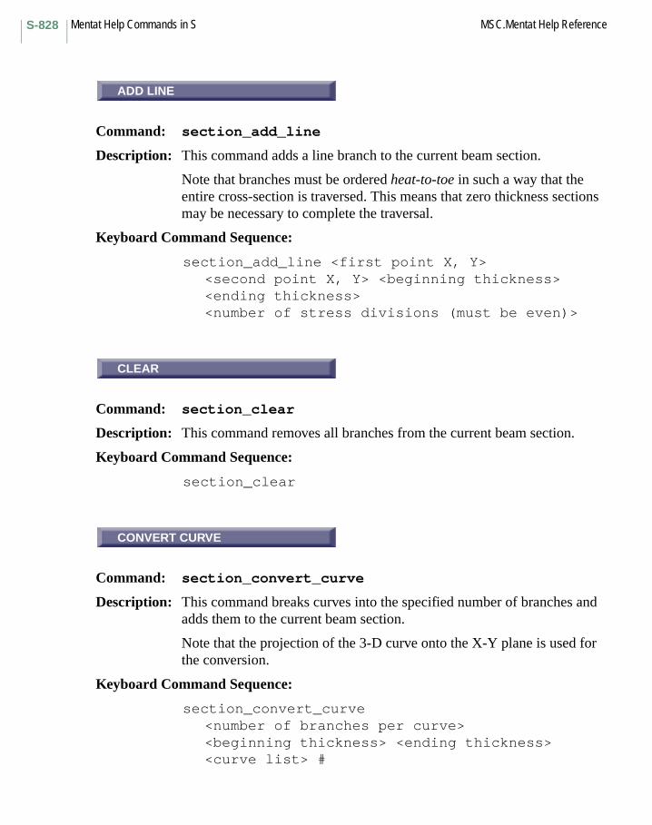
Mentat Help Commands in S MSC.Mentat Help ReferenceS-828
ADD LINE
Command: section_add_line
Description: This command adds a line branch to the current beam section.
Note that branches must be ordered heat-to-toe in such a way that the entire cross-section is traversed. This means that zero thickness sections may be necessary to complete the traversal.
Keyboard Command Sequence:
section_add_line <first point X, Y><second point X, Y> <beginning thickness><ending thickness><number of stress divisions (must be even)>
CLEAR
Command: section_clear
Description: This command removes all branches from the current beam section.
Keyboard Command Sequence:
section_clear
CONVERT CURVE
Command: section_convert_curve
Description: This command breaks curves into the specified number of branches and adds them to the current beam section.
Note that the projection of the 3-D curve onto the X-Y plane is used for the conversion.
Keyboard Command Sequence:
section_convert_curve<number of branches per curve><beginning thickness> <ending thickness><curve list> #
ADD LINE
CLEAR
CONVERT CURVE
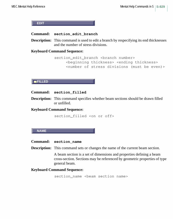
S-829MSC.Mentat Help Reference Mentat Help Commands in S
EDIT
Command: section_edit_branch
Description: This command is used to edit a branch by respecifying its end thicknesses and the number of stress divisions.
Keyboard Command Sequence:
section_edit_branch <branch number><beginning thickness> <ending thickness><number of stress divisions (must be even)>
FILLED
Command: section_filled
Description: This command specifies whether beam sections should be drawn filled or unfilled.
Keyboard Command Sequence:
section_filled <on or off>
NAME
Command: section_name
Description: This command sets or changes the name of the current beam section.
A beam section is a set of dimensions and properties defining a beam cross-section. Sections may be referenced by geometric properties of type general beam.
Keyboard Command Sequence:
section_name <beam section name>
EDIT
FILLED
NAME

Mentat Help Commands in S MSC.Mentat Help ReferenceS-830
REMOVE
Command: section_remove_branch
Description: This command removes branches from the current beam section.
Note that branches must be ordered heat-to-toe in such a way that the entire cross-section is traversed. This means that zero thickness sections may be necessary to complete the traversal.
Keyboard Command Sequence:
section_remove_branch <branch numbers>
SELECT
Menu: SELECT
Description: This menu contains commands for selecting model entities and for creating sets of entities.
ALL IN LIST
Command: select_by_all
Description: This command specifies that the select by commands operate in ALL IN LIST mode. The influence of the select by mode is explained in the help texts on the select by commands.
Also see: select_by_any.
Keyboard Command Sequence:
select_by_all
REMOVE
SELECT
ALL IN LIST
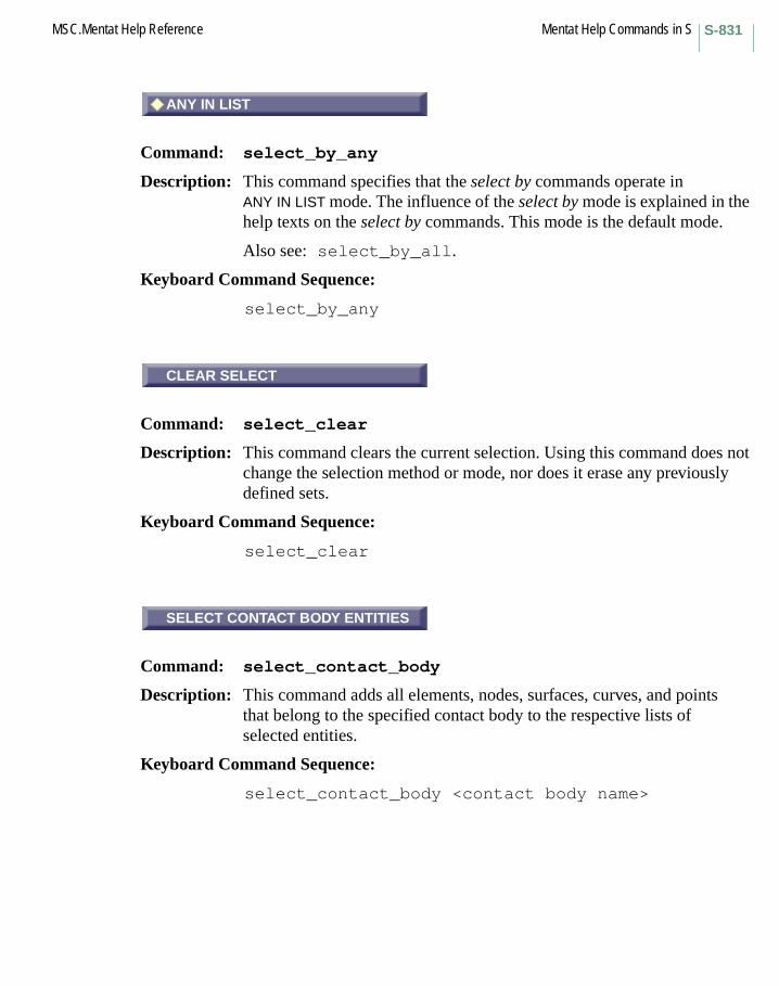
S-831MSC.Mentat Help Reference Mentat Help Commands in S
ANY IN LIST
Command: select_by_any
Description: This command specifies that the select by commands operate in ANY IN LIST mode. The influence of the select by mode is explained in the help texts on the select by commands. This mode is the default mode.
Also see: select_by_all.
Keyboard Command Sequence:
select_by_any
CLEAR SELECT
Command: select_clear
Description: This command clears the current selection. Using this command does not change the selection method or mode, nor does it erase any previously defined sets.
Keyboard Command Sequence:
select_clear
SELECT CONTACT BODY ENTITIES
Command: select_contact_body
Description: This command adds all elements, nodes, surfaces, curves, and points that belong to the specified contact body to the respective lists of selected entities.
Keyboard Command Sequence:
select_contact_body <contact body name>
ANY IN LIST
CLEAR SELECT
SELECT CONTACT BODY ENTITIES

Mentat Help Commands in S MSC.Mentat Help ReferenceS-832
CURVES
Command: select_curves
Description: This command adds curves to the list of selected curves. Once curves are selected, they are used to define a set with the store_curves command.
The method for specifying curves depends on the select method being used (see select_method_single, select_method_path, select_method_box, select_method_user_box, select_method_plane, select_method_flood, select_method_point_dist, select_method_curve_dist, select_method_surface_dist).
Keyboard Command Sequence:
select_curves
CONT BODY
Command: select_curves_cbody
Description: This command adds all curves that belong to the specified contact body to the list of selected curves. Once curves are selected, they are used to define a set with the store_curves command.
Keyboard Command Sequence:
select_curves_cbody <contact body name>
CURVES
CONT BODY

S-833MSC.Mentat Help Reference Mentat Help Commands in S
NODES
Command: select_curves_nodes
Description: This command adds curves to the list of selected curves, based on a list of nodes given by the user. Which curves are added depends on the value of the select by mode:
ANY IN LIST: curves to which any node in the list is attachedALL IN LIST: curves to which all nodes in the list are attached
Once curves are selected, they are used to define a set with the store_curves command.
Keyboard Command Sequence:
select_curves_nodes <node list> #
POINTS
Command: select_curves_points
Description: This command adds curves to the list of selected curves, based on a list of points given by the user. Which curves are added depends on the value of the select by mode:
ANY IN LIST: curves for which any point is included in the listALL IN LIST: curves for which all points are included in the list
Once curves are selected, they are used to define a set with the store_curves command.
Keyboard Command Sequence:
select_curves_points <point list> #
NODES
POINTS
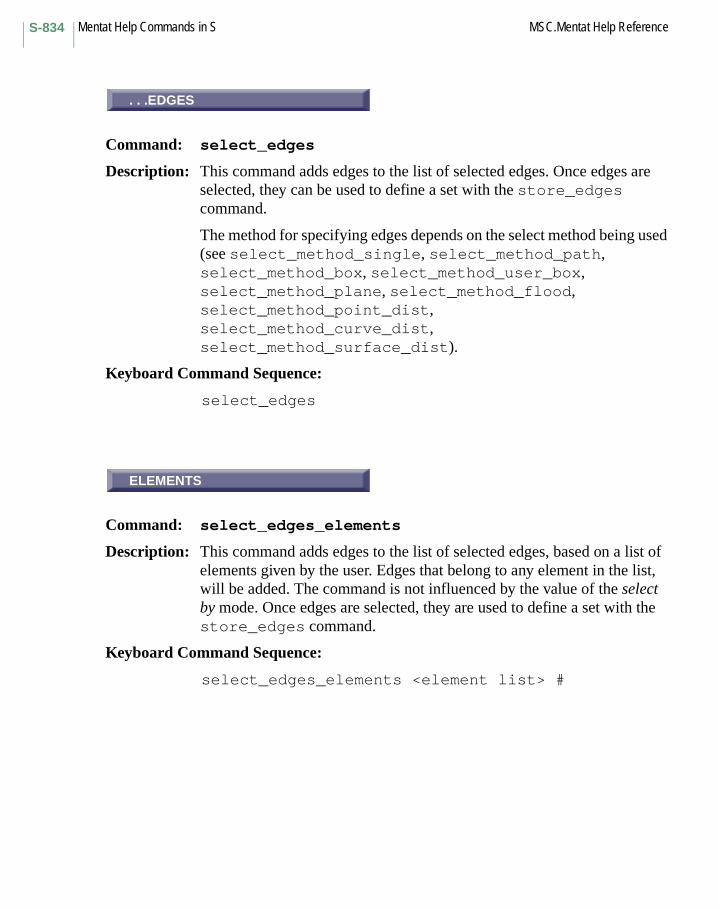
Mentat Help Commands in S MSC.Mentat Help ReferenceS-834
...EDGES
Command: select_edges
Description: This command adds edges to the list of selected edges. Once edges are selected, they can be used to define a set with the store_edges command.
The method for specifying edges depends on the select method being used (see select_method_single, select_method_path, select_method_box, select_method_user_box, select_method_plane, select_method_flood, select_method_point_dist, select_method_curve_dist, select_method_surface_dist).
Keyboard Command Sequence:
select_edges
ELEMENTS
Command: select_edges_elements
Description: This command adds edges to the list of selected edges, based on a list of elements given by the user. Edges that belong to any element in the list, will be added. The command is not influenced by the value of the select by mode. Once edges are selected, they are used to define a set with the store_edges command.
Keyboard Command Sequence:
select_edges_elements <element list> #
. . .EDGES
ELEMENTS
S-835MSC.Mentat Help Reference Mentat Help Commands in S
FACES
Command: select_edges_faces
Description: This command adds edges to the list of selected edges, based on a list of faces given by the user. Which edges are added depends on the value of the select by mode:
ANY IN LIST: edges that belong to any face in the listALL IN LIST: edges that belong to all faces in the list; a maximum of two faces may be given.
Once edges are selected, they are used to define a set with the store_edges command.
Keyboard Command Sequence:
select_edges_faces <face list> #
NODES
Command: select_edges_nodes
Description: This command adds edges to the list of selected edges, based on a list of nodes given by the user. Which edges are added depends on the value of the select by mode:
ANY IN LIST: edges for which any node is included in the listALL IN LIST: edges for which all nodes are included in the list
Once edges are selected, they are used to define a set with the store_edges command.
Keyboard Command Sequence:
select_edges_nodes <node list> #
FACES
NODES
Mentat Help Commands in S MSC.Mentat Help ReferenceS-836
ELEMENTS
Command: select_elements
Description: This command adds elements to the list of selected elements. Once elements are selected, they are used to define a set with the store_elements command.
The method for specifying elements depends on the select method being used (see select_method_single, select_method_path, select_method_box, select_method_user_box, select_method_plane, select_method_flood, select_method_point_dist, select_method_curve_dist, select_method_surface_dist).
Keyboard Command Sequence: select_elements
CONT BODY
Command: select_elements_cbody
Description: This command adds all elements that belong to the specified contact body to the list of selected elements. Once elements are selected, they are used to define a set with the store_elements command.
Keyboard Command Sequence: select_elements_cbody <contact body name>
OK
Command: select_elements_class
Description: This command adds all elements in the model of the specified class to the list of selected elements. Once elements are selected, they are used to define a set with the store_elements command.
Keyboard Command Sequence: select_elements_class <element class>
ELEMENTS
CONT BODY
OK
S-837MSC.Mentat Help Reference Mentat Help Commands in S
FACES
Command: select_elements_faces
Description: This command adds elements to the list of selected elements, based on a list of faces given by the user. Which elements are added depends on the value of the select by mode:
ANY IN LIST: elements for which any face is included in the listALL IN LIST: elements for which all faces are included in the list
Once elements are selected, they are used to define a set with the store_elements command.
Keyboard Command Sequence:
select_elements_faces <face list> #
GEOMETRY
Command: select_elements_geometry
Description: This command adds all elements in the model with the specified geometric property to the list of selected elements. Once elements are selected, they are used to define a set with the store_elements command.
Keyboard Command Sequence:
select_elements_geometry <geometry name>
MATERIAL
Command: select_elements_material
Description: This command adds all elements in the model with the specified material to the list of selected elements. Once elements are selected, they are used to define a set with the store_elements command.
Keyboard Command Sequence: select_elements_material <material name>
FACES
GEOMETRY
MATERIAL
Mentat Help Commands in S MSC.Mentat Help ReferenceS-838
NODES
Command: select_elements_nodes
Description: This command adds elements to the list of selected elements, based on a list of nodes given by the user. Which elements are added depends on the value of the select by mode:
ANY IN LIST: elements for which any node is included in the listALL IN LIST: elements for which all nodes are included in the list
Once elements are selected, they are used to define a set with the store_elements command.
Keyboard Command Sequence: select_elements_nodes <node list> #
ORIENT
Command: select_elements_orient
Description: This command adds all elements in the model with the specified orientation to the list of selected elements. Once elements are selected, they are used to define a set with the store_elements command.
Keyboard Command Sequence:
select_elements_orient <orient name>
TYPE
Command: select_elements_type
Description: This command adds all elements in the model with the specified Marc element type to the list of selected elements. Once elements are selected, they are used to define a set with the store_elements command.
Keyboard Command Sequence:
select_elements_type <Marc element type>
NODES
ORIENT
TYPE

S-839MSC.Mentat Help Reference Mentat Help Commands in S
...FACES
Command: select_faces
Description: This command adds faces to the list of selected faces. Once faces are selected, they are used to define a set with the store_faces command.
The method for specifying faces depends on the select method being used (see select_method_single, select_method_path, select_method_box, select_method_user_box, select_method_plane, select_method_flood, select_method_point_dist, select_method_curve_dist, select_method_surface_dist).
Keyboard Command Sequence:
select_faces
EDGES
Command: select_faces_edges
Description: This command adds faces to the list of selected faces, based on a list of edges given by the user. Which faces are added depends on the value of the select by mode:
ANY IN LIST: faces for which any edge is included in the listALL IN LIST: faces for which all edges are included in the list
Once faces are selected, they are used to define a set with the store_faces command.
Keyboard Command Sequence:
select_faces_edges <edge list> #
...FACES
EDGES
Mentat Help Commands in S MSC.Mentat Help ReferenceS-840
ELEMENTS
Command: select_faces_elements
Description: This command adds faces to the list of selected faces, based on a list of elements given by the user. Faces that belong to any element in the list, are added. The command is not influenced by the value of the select by mode. Once faces are selected, they are used to define a set with the store_faces command.
Keyboard Command Sequence: select_faces_elements <element list> #
NODES
Command: select_faces_nodes
Description: This command adds faces to the list of selected faces, based on a list of nodes given by the user. Which faces are added depends on the value of the select by mode:
ANY IN LIST: faces for which any node is included in the listALL IN LIST: faces for which all nodes are included in the list
Once faces are selected, they are used to define a set with the store_faces command.
Keyboard Command Sequence: select_faces_nodes <node list> #
NONE
Command: select_filter_none
Description: This command specifies that no filters will be used by the select commands. You may specify filtering with the select_filter_outline and select_filter_surface commands.
Keyboard Command Sequence: select_filter_none
ELEMENTS
NODES
NONE
S-841MSC.Mentat Help Reference Mentat Help Commands in S
OUTLINE
Command: select_filter_outline
Description: This command specifies that outline filtering are used by the select command. With outline filtering, only those entities on the outline of the model are selected by the select commands.
Keyboard Command Sequence:
select_filter_outline
SURFACE
Command: select_filter_surface
Description: This command specifies that surface filtering are used by the select command. With surface filtering, only those entities on the surface of the model are selected by the select commands.
Keyboard Command Sequence:
select_filter_surface
ASSOCIATION
Command: select_method_association
Description: This command specifies that select commands use the association method. This method allows the user to select items and other items in the set that those items belong to will also become selected.
Keyboard Command Sequence:
select_method_association
OUTLINE
SURFACE
ASSOCIATION
Mentat Help Commands in S MSC.Mentat Help ReferenceS-842
BOX
Command: select_method_box
Description: This command specifies that select commands use the box method. This method allows the user to select items within a specified region in space. All items that fall within the specified box (global coordinate system) become selected.
Keyboard Command Sequence: select_method_box
CURVE DIST.
Command: select_method_curve_dist
Description: This command specifies that select commands use the curve distance method. This method allows the user to select items that fall within the SELECT DISTANCE of a curve. The SELECT DISTANCE can be specified using the *set_select_distance command. Only items that fall entirely within the specified distance will be selected.
This button is located under the UTILS->SELECT->METHOD menu.
Keyboard Command Sequence: select_method_curve_dist
FLOOD
Command: select_method_flood
Description: This command specifies that select commands use the flood method. To use this method, first define a boundary of selected nodes and then activate the flood method. The method then works by selecting all entities of the desired type (points, curves, surfaces, nodes, or elements) that are connected to the specified node and are within the boundary of previously selected nodes.
Keyboard Command Sequence: select_method_flood
BOX
CURVE DIST.
FLOOD
S-843MSC.Mentat Help Reference Mentat Help Commands in S
PATH
Command: select_method_path
Description: This command specifies that select commands use the path method. This method allows the user to select connected nodes or points along a path from the first entity specified to the last. You may specify only the beginning and end of the path, or choose entities at various location along the path.
Keyboard Command Sequence: select_method_path
PLANE
Command: select_method_plane
Description: This command specifies that select commands use the plane method. This method allows the user to select nodes or elements in a specified plane by choosing an element face. All nodes or elements which are in the plane specified by the centroid of the face and the face normal at the centroid will be selected.
Keyboard Command Sequence: select_method_plane
POINT DIST.
Command: select_method_point_dist
Description: This command specifies that select commands use the point distance method. This method allows the user to select items that fall within the SELECT DISTANCE of a point in space. The SELECT DISTANCE can be specified using the *set_select_distance command. Only items that fall entirely within the specified distance will be selected.
This button is located under the UTILS->SELECT->METHOD menu.
Keyboard Command Sequence: select_method_point_dist
PATH
PLANE
POINT DIST.
Mentat Help Commands in S MSC.Mentat Help ReferenceS-844
SINGLE
Command: select_method_single
Description: This command specifies that select commands use the single method. This method allow the user to select entities singly by specifying their ids. This method is the default method.
Keyboard Command Sequence: select_method_single
SURFACE DIST.
Command: select_method_surface_dist
Description: This command specifies that select commands use the surface distance method. This method allows the user to select items that fall within the SELECT DISTANCE of a surface. The SELECT DISTANCE can be specified using the *set_select_distance command. Only items that fall entirely within the specified distance will be selected.
This button is located under the UTILS->SELECT->METHOD menu.
Keyboard Command Sequence: select_method_surface_dist
USER BOX
Command: select_method_user_box
Description: This command specifies that select commands use the box method in the current user coordinate system. This is similar to the select_method_box command, except that coordinates are first transformed to the user coordinate system before being checked if they fall within the specified box. Only items that fall entirely within the box are selected.
If the user coordinate system is RECTANGULAR, the box is defined by specifying the ranges in the X-, Y-, and Z-direction of the coordinate system.
If the user coordinate system is CYLINDRICAL, the box is defined by specifying the ranges in the R-, PHI-, and Z-direction of the coordinate system.
SINGLE
SURFACE DIST.
USER BOX
S-845MSC.Mentat Help Reference Mentat Help Commands in S
If the user coordinate system is SPHERICAL, the box is defined by specifying the ranges in the R-, PHI-, and THETA-direction of the coordinate system. The angles that specify the range in the THETA direction must be between -90 and +90 degrees.
This button is located under the UTILS->SELECT->METHOD menu.
Keyboard Command Sequence: select_method_user_box
AND
Command: select_mode_and
Description: This command specifies that select commands operate in and mode. In this mode, additionally selected entities are and-ed with those already in the selected list, thus adding them to the list. This mode is the default mode.
Also see: select_mode_except, select_mode_invert, and select_mode_intersect.
Keyboard Command Sequence: select_mode_and
EXCEPT
Command: select_mode_except
Description: This command specifies that select commands operate in except mode. In this mode, additionally selected entities are removed from the list of selected entities.
Also see: select_mode_and, select_mode_invert, and select_mode_intersect.
Keyboard Command Sequence:select_mode_except
AND
EXCEPT
Mentat Help Commands in S MSC.Mentat Help ReferenceS-846
INTERSECT
Command: select_mode_intersect
Description: This command specifies that select commands operate in intersect mode. In this mode, additionally selected entities are intersected with the current list of selected entities to form the new list.
Also see: select_mode_and, select_mode_except, and select_mode_invert.
Keyboard Command Sequence: select_mode_intersect
INVERT
Command: select_mode_invert
Description: This command specifies that select commands operate in invert mode. In this mode, additionally selected entities are added to the list of selected entities if they do NOT belong to it and are removed if they do already belong to it.
Also see: select_mode_and, select_mode_except, and select_mode_intersect.
Keyboard Command Sequence: select_mode_invert
NODES
Command: select_nodes
Description: This command adds nodes to the list of selected nodes. Once nodes are selected, they are used to define a set with the store_nodes command.
The method for specifying nodes depends on the select method being used (see select_method_single, select_method_path, select_method_box, select_method_user_box, select_method_plane, select_method_flood, select_method_point_dist,
INTERSECT
INVERT
NODES
S-847MSC.Mentat Help Reference Mentat Help Commands in S
select_method_curve_dist, select_method_surface_dist).
Keyboard Command Sequence: select_nodes
CURVES
Command: select_nodes_curves
Description: This command adds nodes to the list of selected nodes, based on a list of curves given by the user. Nodes that are attached to any curve in the list, will be added. The command is not influenced by the value of the select by mode. Once nodes are selected, they are used to define a set with the store_nodes command.
Keyboard Command Sequence:
select_nodes_curves <curve list> #
EDGES
Command: select_nodes_edges
Description: This command adds nodes to the list of selected nodes, based on a list of edges given by the user. Which nodes are added depends on the value of the select by mode:
ANY IN LIST: nodes that belong to any edge in the listALL IN LIST: nodes that belong to all edges in the list
Once nodes are selected, they are used to define a set with the store_nodes command.
Keyboard Command Sequence:
select_nodes_edges <edge list> #
CURVES
EDGES

Mentat Help Commands in S MSC.Mentat Help ReferenceS-848
ELEMENTS
Command: select_nodes_elements
Description: This command adds nodes to the list of selected nodes, based on a list of elements given by the user. Which nodes are added depends on the value of the select by mode:
ANY IN LIST: nodes that belong to any element in the listALL IN LIST: nodes that belong to all elements in the list
Once nodes are selected, they are used to define a set with the store_nodes command.
Keyboard Command Sequence: select_nodes_elements <element list> #
FACES
Command: select_nodes_faces
Description: This command adds nodes to the list of selected nodes, based on a list of faces given by the user. Which nodes are added depends on the value of the select by mode:
ANY IN LIST: nodes that belong to any face in the listALL IN LIST: nodes that belong to all faces in the list
Once nodes are selected, they are used to define a set with the store_nodes command.
Keyboard Command Sequence: select_nodes_faces <face list> #
POINTS
Command: select_nodes_points
Description: This command adds nodes to the list of selected nodes, based on a list of points given by the user. Nodes that are attached to any point in the list, are added. The command is not influenced by the value of the select by mode.
ELEMENTS
FACES
POINTS
S-849MSC.Mentat Help Reference Mentat Help Commands in S
Once nodes are selected, they are used to define a set with the store_nodes command.
Keyboard Command Sequence:
select_nodes_points <point list> #
SURFACES
Command: select_nodes_surfaces
Description: This command adds nodes to the list of selected nodes, based on a list of surfaces given by the user. Which nodes are added depends on the value of the select by mode:
ANY IN LIST: nodes that are attached to any surface in the listALL IN LIST: nodes that are attached to all surfaces in the list; a maximum of two surfaces may be given.
Once nodes are selected, they are used to define a set with the store_nodes command.
Keyboard Command Sequence:
select_nodes_surfaces <surface list> #
TRANSFORM
Command: select_nodes_transform
Description: This command adds all nodes in the model with the specified transformation to the list of selected nodes.
Once nodes are selected, they are used to define a set with the store_nodes command.
Keyboard Command Sequence:
select_nodes_transform <transform name>
SURFACES
TRANSFORM
Mentat Help Commands in S MSC.Mentat Help ReferenceS-850
POINTS
Command: select_points
Description: This command adds points to the list of selected points. Once points are selected, they are used to define a set with the store_points command.
The method for specifying points depends on the select method being used (see select_method_single, select_method_path, select_method_box, select_method_user_box, select_method_plane, select_method_flood, select_method_point_dist, select_method_curve_dist, select_method_surface_dist).
Keyboard Command Sequence:
select_points
CURVES
Command: select_points_curves
Description: This command adds points to the list of selected points, based on a list of curves given by the user. Which points are added depends on the value of the select by mode:
ANY IN LIST: points that belong to any curve in the listALL IN LIST: points that belong to all curves in the list
Once points are selected, they are used to define a set with the store_points command.
Keyboard Command Sequence:
select_points_curves <curve list> #
POINTS
CURVES

S-851MSC.Mentat Help Reference Mentat Help Commands in S
NODES
Command: select_points_nodes
Description: This command adds points to the list of selected points, based on a list of nodes given by the user. Which points are added depends on the value of the select by mode:
ANY IN LIST: points to which any node in the list is attachedALL IN LIST: points to which all nodes in the list are attached
Once points are selected, they are used to define a set with the store_points command.
Keyboard Command Sequence: select_points_nodes <node list> #
SURFACES (DFN)
Command: select_points_surfaces
Description: This command adds points to the list of selected points, based on a list of surfaces given by the user. Which points are added depends on the value of the select by mode:
ANY IN LIST: defining points that belong to any surface in the listALL IN LIST: defining points that belong to all surfaces in the list
Once points are selected, they are used to define a set with the store_points command.
Keyboard Command Sequence: select_points_surfaces <surface list> #
RESET
Command: select_reset
Description: This command resets select parameters, method, mode, filter, and select by mode to their default values. This command does not alter the lists of currently selected entities.
Keyboard Command Sequence: select_reset
NODES
SURFACES (DFN)
RESET
Mentat Help Commands in S MSC.Mentat Help ReferenceS-852
SELECT BY SCALAR VALUE
Menu: SELECT BY SCALAR VALUE
Description: This menu provides tools for adding nodes or elements to the list of selected nodes or elements based upon the values of the scalar quantity that is currently being post processed. Only nodes or elements that are currently visible and that are not removed from post plotting using the unpost_nodes or unpost_elements commands are considered. The commands always consider the extrapolated values of the scalar quantity at the nodes of the elements based on the current extrapolation scheme, even when selecting elements.
If some elements have been isolated using the post_isolated command (i.e. averaging of element values across element edges is switched off between the set of isolated elements and the set of non isolated elements) the commands will consider the isolated values and the nodes of those elements.
SELECT BY EXTREMES
These tools add all nodes or elements to the list of selected nodes or elements in which the scalar quantity assumes its minimum or maximum value.
SELECT NODES IN RANGESELECT ELEMENTS IN RANGE
These commands add nodes or elements to the list of selected nodes or elements in which the scalar quantity assumes values in a given RANGE.
Keyboard Command Sequence: select_elements_scalar_minselect_elements_scalar_max
select_nodes_scalar_minselect_nodes_scalar_max
select_scalar_range <lower_bound> <upper_bound> select_nodes_scalar_rangeselect_elements_scalar_range
Related Commands:post_extrap_linear/post_extrap_translate/post_extrap_average
SELECT BY SCALAR VALUE
S-853MSC.Mentat Help Reference Mentat Help Commands in S
post_elements/unpost_elementspost_nodes/unpost_nodespost_isolate
Other Buttons with the same description:MINIMUMRANGESELECT ELEMENTS IN RANGESELECT NODES IN RANGE
SELECT SET
Command: select_sets
Description: This command selects a previously defined set of entities (see store_curves, store_edges, store_elements, store_faces, store_nodes, store_points, and store_surfaces) and applies them to the current list of selected entities with the current select method, mode, and filter. You must specify the name of a previously defined set.
Keyboard Command Sequence: select_set <set name>
SURFACES
Command: select_surfaces
Description: This command adds surfaces to the list of selected surfaces. Once surfaces are selected, they are used to define a set with the store_surfaces command.
The method for specifying surfaces depends on the select method being used (see select_method_single, select_method_path, select_method_box, select_method_user_box, select_method_plane, select_method_flood, select_method_point_dist, select_method_curve_dist, select_method_surface_dist).
Keyboard Command Sequence: select_surfaces
SELECT SET
SURFACES
Mentat Help Commands in S MSC.Mentat Help ReferenceS-854
CONT BODY
Command: select_surfaces_cbody
Description: This command adds all surfaces that belong to the specified contact body to the list of selected surfaces. Once surfaces are selected, they are used to define a set with the store_surfaces command.
Keyboard Command Sequence: select_surfaces_cbody <contact body name>
NODES
Command: select_surfaces_nodes
Description: This command adds surfaces to the list of selected surfaces, based on a list of nodes given by the user. Which surfaces are added depends on the value of the select by mode:
ANY IN LIST: surfaces to which any node in the list is attachedALL IN LIST: surfaces to which all nodes in the list are attached
Once surfaces are selected, they are used to define a set with the store_surfaces command.
Keyboard Command Sequence:
select_surfaces_nodes <node list> #
POINTS (DFN)
Command: select_surfaces_points
Description: This command adds surfaces to the list of selected surfaces, based on a list of points given by the user. Which surfaces are added depends on the value of the select by mode:
ANY IN LIST: surfaces for which any defining point is included in the listALL IN LIST: surfaces for which all defining points are included in the list
CONT BODY
NODES
POINTS (DFN)

S-855MSC.Mentat Help Reference Mentat Help Commands in S
Once surfaces are selected, they are used to define a set with the store_surfaces command.
Keyboard Command Sequence: select_surfaces_points <point list> #
CURVES
Command: select_surfaces_trim_curves
Description: This command adds surfaces to the list of selected surfaces, based on a list of curves given by the user. Which surfaces are added depends on the value of the select by mode:
ANY IN LIST: surfaces for which any trimming curve is included in the listALL IN LIST: surfaces for which all trimming curves are included in the list
Once surfaces are selected, they are used to define a set with the store_surfaces command.
Keyboard Command Sequence: select_surfaces_trim_curves <curve list> #
POINTS (TRIM)
Command: select_surfaces_trim_points
Description: This command adds surfaces to the list of selected surfaces, based on a list of points given by the user. Which surfaces are added depends on the value of the select by mode:
ANY IN LIST: surfaces for which any trimming point is included in the listALL IN LIST: surfaces for which all trimming points are included in the list
Once surfaces are selected, they are used to define a set with the store_surfaces command.
Keyboard Command Sequence: select_surfaces_trim_points <point list> #
CURVES
POINTS (TRIM)

Mentat Help Commands in S MSC.Mentat Help ReferenceS-856
SURFACES
Command: select_trim_curves_surfaces
Description: This command adds curves to the list of selected curves, based on a list of surfaces given by the user. The trimming curves of any surface in the list are added. The command is not influenced by the value of the select by mode.
Once curves are selected, they are used to define a set with the store_curves command.
Keyboard Command Sequence: select_trim_curves_surfaces <surface list> #
SURFACES (TRIM)
Command: select_trim_points_surfaces
Description: This command adds points to the list of selected points, based on a list of surfaces given by the user. The trimming points of any surface in the list are added. The command is not influenced by the value of the select by mode.
Once points are selected, they are used to define a set with the store_points command.
Keyboard Command Sequence: select_trim_points_surfaces <surface list> #
SEPFOR
Subroutine: SEPFOR
Description: The user subroutine SEPFOR allows you to define the separation force in conjunction with the model definition option CONTACT. The separation forces, FNORM and FTANG, are either calculated by the program or entered through the CONTACT option, and are then passed into this subroutine. You decide whether this magnitude at the current increment is good enough to determine whether separation will occur.
FNORM is the normal reaction force above which a node in contact will separate from a surface. Any compressive or negative value indicates
SURFACES
SURFACES (TRIM)
SEPFOR

S-857MSC.Mentat Help Reference Mentat Help Commands in S
real contact, while a positive reaction force indicates a tendency to separate. The default is taken as the maximum value of the residual force in the structure for the current increment. This value can be reset in the input deck. Defining a small value may result in an increased number of iterations. Defining a large value will eliminate the possibility of separation.
set_acis_formatted
Command: set_acis_formatted
Description: This command sets the format of acis files read and written with the read_acis and write_acis commands. Formatted acis files are ascii text files and are editable and portable across machine architectures. Unformatted (binary) database files are not always architecture independent but are smaller and are processed more quickly.
Keyboard Command Sequence: set_acis_formatted <on or off>
ANNOTATIONS
Command: set_annotations
Description: This command toggles the display of annotations. When ON, all annotations are displayed. When OFF, no annotations are displayed. Annotations are strings of text that are used to describe what is being displayed in a view.
Keyboard Command Sequence: set_annotations <on or off>
Another Button with the same description:DISPLAY ANNOTATIONS
set_acis_formatted
ANNOTATIONS
Mentat Help Commands in S MSC.Mentat Help ReferenceS-858
CORIOLIS
Command: set_apply_coriolis
Description: This command specifies whether or not Coriolis type loading will be applied for the current centrifugal boundary condition.
Keyboard Command Sequence:
set_apply_coriolis <on or off>
ENTERED VALUES
Command: set_apply_entered
Description: This command specifies that values for the current boundary condition are being entered by the user (as opposed to being provided through a user subroutine; see set_apply_usersub).
Keyboard Command Sequence:
set_apply_entered
BOUND CONDS
Command: set_apply_labels
Description: This command toggles the display of boundary condition labels.
Keyboard Command Sequence:
set_apply_labels <on or off>
POST FILE
Command: set_apply_post_tape
Description: This command specifies that values for the current state variable boundary condition will be determined at run time by reading a previously generated post file.
Keyboard Command Sequence: set_apply_post_tape
CORIOLIS
ENTERED VALUES
BOUND CONDS
POST FILE

S-859MSC.Mentat Help Reference Mentat Help Commands in S
USER SUB.
Command: set_apply_usersub
Description: This command specifies that Marc should call the appropriate user subroutine for this boundary condition during the analysis. If the user subroutine has been invoked, there is no need to enter values for the application since they will be ignored by Marc in lieu of the values provided by the subroutine.
If the user subroutine is used, the FORTRAN source code file must exist in your current working directory, so that it can be compiled and linked in with Marc when you submit the job (see job_usersub_file).
Keyboard Command Sequence:
set_apply_usersub <on or off>
BOUND CONDS
Command: set_applys
Description: This command toggles the display of boundary conditions.
Keyboard Command Sequence:
set_applys <on or off>
EDGES
Command: set_arrow_heads
Description: This command toggles the plotting of head of the arrows when pre- and postprocessing are plotted. By default, heads are on. You will need to do a DRAW, REDRAW, or REGEN to display the change.
Also see: arrows_solid and arrow_wireframe.
Keyboard Command Sequence:
set_arrow_heads <on or off>
USER SUB.
BOUND CONDS
HEADS

Mentat Help Commands in S MSC.Mentat Help ReferenceS-860
EDGES
Command: set_arrow_lines
Description: This command toggles the plotting of facet edges when pre- and postprocessing arrows are plotted in solid mode. Be sure to also use the arrows_solid command to select solid plotting of arrows (wireframe plotting is the default). By default, facet edges are on. You may wish to turn them off if you have turned lighting on. You will need to do a DRAW, REDRAW, or REGEN to display the change.
Also see: arrows_solid and arrow_facets.
Keyboard Command Sequence:
set_arrow_lines <on or off>
DIRECTION
Command: set_attach_direction
Description: This command sets the attach direction to be used in directed mode, while attaching edges to curves and faces to surfaces. You must specify the components of a vector defining the attach direction.
Also see: attach_mode_directedattach_edges_curveattach_faces_surfaceattach_elements_curveattach_elements_surface
Keyboard Command Sequence: set_attach_direction <XYZ components of
direction>
EDGES
DIRECTION

S-861MSC.Mentat Help Reference Mentat Help Commands in S
DISTANCE
Command: set_attach_distance
Description: This command sets the distance limit for attaching nodes to points, edges to curves, and faces to surfaces. Items that fall (either totally or partially) beyond the specified distance will not be attached if the attach limit has been activated.
Also see: set_attach_limitattach_nodes_pointattach_edges_curveattach_faces_surfaceattach_elements_curveattach_elements_surface
Keyboard Command Sequence: set_attach_distance <distance>
DIVISIONS
Command: set_attach_divisions
Description: This command sets the number of curve (surface) divisions used by the attach commands for determining node locations, when moving nodes to curves (surfaces). The higher the specified divisions the more accurately the nodes or elements will be attached.
Also see: attach_edges_curveattach_faces_surfaceattach_elements_curveattach_elements_surface
Keyboard Command Sequence: set_attach_divisions <divisions>
DISTANCE
DIVISIONS
Mentat Help Commands in S MSC.Mentat Help ReferenceS-862
ON
Command: set_attach_limit
Description: This command toggles the attach limit mode. If this mode is activated, attaching of nodes, edges and faces will be limited to those items that fall entirely within the distance limit specified by the set_attach_distance command (DISTANCE button).
Also see: set_attach_distanceattach_nodes_pointattach_edges_curveattach_faces_surfaceattach_elements_curveattach_elements_surface
Keyboard Command Sequence:t set_attach_limit <on or off>
TOLERANCE
Command: set_attach_tolerance
Description: This command sets the tolerance used by the attach commands for determining node locations when moving nodes to curves and surfaces. The smaller the specified tolerance the more accurately the nodes will be attached.
Also see: attach_edges_curveattach_faces_surfaceattach_elements_curveattach_elements_surface
Keyboard Command Sequence: set_attach_tolerance <tolerance>
ON
TOLERANCE
S-863MSC.Mentat Help Reference Mentat Help Commands in S
AUTOMATIC
Command: set_auto_arrow
Description: This command toggles the automatic scaling of preprocessing arrows. By default, the mode is ON making the arrow length a fraction of the overall model size. This fraction may be changed from the default value of 0.1 with the auto_arrow_length command. When the mode is OFF, this fraction is ignored and the arrow length is then an absolute value, independent of the model size. This length may also be changed from its default value of 0.2 with the arrow_length command.
Also see: auto_arrow_length and arrow_length.
Keyboard Command Sequence:
set_auto_arrow <on or off>
Another Button with the same description:
MANUAL
AUTOMATIC
Command: set_automag
Description: This command toggles the automatic deformation scaling for results viewing. By default, the mode is OFF and the magnification is 1.0 (actual displacements). When the mode is ON, the user specified magnification is ignored and the deformation scaling is set such that displacements are easily viewed on the screen.
Keyboard Command Sequence: set_automag <on or off>
Another Button with the same description:
MANUAL
AUTOMATIC
AUTOMATIC
Mentat Help Commands in S MSC.Mentat Help ReferenceS-864
AUTOMATIC
Command: set_autorange
Description: This command toggles automatic plotting range for contour plots. The default is on which means that the global maximum and minimum will be used. When the option is off, the user specified scale will be used, which is set by using the SET LIMITS button (range command). By using the COPY LIMITS button (copy_autorange command), the range will be set to the current increment’s min and max values.
Also see help: copy_autorange and range.
Keyboard Command Sequence: set_autorange <on or off>
Another Button with the same description:MANUAL
AUTOMATIC
Command: set_autovec
Description: This command toggles automatic vector scaling during post plotting. When on, the vectors are scaled to be 5 percent of the size of the model. When off, the vectors are scaled by the magnification factor set by the set_vecmag command.
Keyboard Command Sequence: set_autovec <on or off>
Another Button with the same description:MANUAL
BREAK CURVES
Command: set_break_crvs
Description: This command toggles the break_curves parameter which tells that the command clean_surface_loops will break curves or not.
Keyboard Command Sequence: set_break_crvs <on or off>
AUTOMATIC
AUTOMATIC
BREAK CURVES

S-865MSC.Mentat Help Reference Mentat Help Commands in S
BUFFERED
Command: set_buffered
Description: This command toggles graphics double-buffering.
– When double-buffering is ON, graphical changes to the program are made to an out-of-sight area, and then copied to the screen upon completion. Thus, only finished images are seen.
– When double-buffering is OFF, all graphical changes to the program are seen as they occur.
Double-buffering makes the program look smoother, but on some systems, it makes the program run slower, requires more memory, or displays its images with too much halftoning, which degrades image quality. By default, double-buffering is ON.
Keyboard Command Sequence:
set_buffered <on or off>
Another Button with the same description:
DIRECT
2-D
Command: cavity_option
Description: This command toggles the dimension of cavity between two-dimensional and three-dimensional. It is located under the MESH GENERATION-> CAVITIES (DIMENSION) menu.
Keyboard Command Sequence:
cavity_option <dimension> <2D or 3D>
Another Button with the same description:
3-D
BUFFERED
2-D

Mentat Help Commands in S MSC.Mentat Help ReferenceS-866
QUAD (4)
Command: set_change_class
Description: This command sets the element class to which elements will be changed by the change_class command. Valid classes, grouped by family are as follows:
Keyboard Command Sequence: set_change_class <class>
Other Buttons with the same description:HEX (12)HEX (20)HEX (27)HEX (8)LINE (2)LINE (3)PENTA (15)PENTA (6)QUAD (6)QUAD (8)QUAD (9)TETRA (10)TETRA (4)TRIA (3)TRIA (6)
SPECIAL MODE
Command: set_change_mode
Description: This command specifies a special mode of operation for the *change_elements_class command:
– When changing quad4 elements into tria3 elements, only two tria3 elements will be generated for every quad4 rather than the normal four. The converse operation changes one tria3 element into three quad4 elements, instead of into a single collapsed element.
Lines: line2, line3Triangles: tria3, tria6Quads: quad4, quad6, quad8, quad9 Tetras: tetra4, tetra10Hexahedrals: hex8, hex12, hex20, hex27Pentas: penta6, penta15
QUAD (4)
SPECIAL MODE
S-867MSC.Mentat Help Reference Mentat Help Commands in S
– When changing tetra4 and penta6 elements into hex8 elements, the tetra4 elements are replaced by four hex8 elements and the penta6 elements are replaced by three hex 8 element, instead of by collapsed hex8 elements.
Keyboard Command Sequence:set_change_mode <on or off>
BIAS FACTORS
Command: set_convert_bias_factors
Description: This command sets the bias factors in the U and V- directions used by convert commands. Bias factors are numbers between -1 and 1. Positive bias factors skew new entity creation locations in the positive direction, i.e. more entities are created in the positive direction. Negative bias factors skew new entity creation locations in the negative direction. Biasing is parabolic. Zero factors produce evenly distributed entities.
Singularities may occur if the magnitude of the bias factor is greater than one third.
Keyboard Command Sequence: set_convert_bias_factors <U-direction factor>
<V-direction factor>
DIVISIONS
Command: set_convert_divisions
Description: This command sets the number of divisions used by convert commands, i.e. the number of entities created from each specified entity.
Keyboard Command Sequence: set_convert_divisions <number in U-direction>
<number in V-direction>
BIAS FACTORS
DIVISIONS

Mentat Help Commands in S MSC.Mentat Help ReferenceS-868
SET
Command: set_csect_control_node
Description: This command sets the control node of the current cross-section. The control node has one degree of freedom, which is seen as the shortening of the cross-section elements in the normal direction of the cross-section. Alternatively, the option generate_csect_control_node can be used to create a control node and assign it to the current cross-section.
Keyboard Command Sequence:
set_csect_control_node <node>
DIRECTION
Command: set_curve_direction
Description: This command toggles the drawing of an arrowhead on each curve, which points in the direction the curve is defined in. Thus, for a given curve, the arrowhead points in the direction its curve is traversed when that curve is evaluated in an increasing direction in parametric space.
Keyboard Command Sequence:
set_curve_direction <on or off>
set_curve_divisions
Command: set_curve_divisions
Description: This command sets the number of subdivisions to be used when plotting curves.
Keyboard Command Sequence:
set_curve_divisions <divisions>
SET
DIRECTION
set_curve_divisions

S-869MSC.Mentat Help Reference Mentat Help Commands in S
CURVES
Command: set_curve_labels
Description: This command toggles the labeling of curves with their ids.
Keyboard Command Sequence:
set_curve_labels <on or off>
CURVE TYPE
Menu: CURVE TYPE
Description: This button toggles the type of curve to create. Subsequent add_curves commands will create curves of this type. Available curve types are:
Miscellaneous types:
LINE A straight line between two points.
BEZIER A bezier curve defined by a list of control points.
CUBIC SPLINE A cubic spline curve that interpolates a list of vertex points.
INTERPOLATE A cubic NURBS curve that interpolates a list of vertex points.
NURB A general NURBS curve given by a complete definition: the number of control points, the curve order, a list of control points, a list of homogeneous coordinates, and a knot vector.
POLY LINE A piecewise straight line between given points.
COMPOSITE A curve that combines a list of curves into one single curve. The curves must lie end-to-end to each other and can be given in any order.
TANGENT A straight line that is tangent to an existing curve. Input is an end point of a curve and the length of the new curve.
CURVES
CURVE TYPE
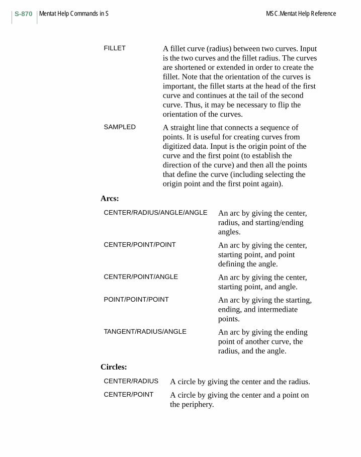
Mentat Help Commands in S MSC.Mentat Help ReferenceS-870
Arcs:
Circles:
FILLET A fillet curve (radius) between two curves. Input is the two curves and the fillet radius. The curves are shortened or extended in order to create the fillet. Note that the orientation of the curves is important, the fillet starts at the head of the first curve and continues at the tail of the second curve. Thus, it may be necessary to flip the orientation of the curves.
SAMPLED A straight line that connects a sequence of points. It is useful for creating curves from digitized data. Input is the origin point of the curve and the first point (to establish the direction of the curve) and then all the points that define the curve (including selecting the origin point and the first point again).
CENTER/RADIUS/ANGLE/ANGLE An arc by giving the center, radius, and starting/ending angles.
CENTER/POINT/POINT An arc by giving the center, starting point, and point defining the angle.
CENTER/POINT/ANGLE An arc by giving the center, starting point, and angle.
POINT/POINT/POINT An arc by giving the starting, ending, and intermediate points.
TANGENT/RADIUS/ANGLE An arc by giving the ending point of another curve, the radius, and the angle.
CENTER/RADIUS A circle by giving the center and the radius.
CENTER/POINT A circle by giving the center and a point on the periphery.
S-871MSC.Mentat Help Reference Mentat Help Commands in S
Other Buttons with the same description:
BEZIERCOMPOSITECUBIC SPLINEFILLETINTERPOLATENURBPOLY LINESAMPLEDTANGENT
CENTER/POINT
Command: set_curve_type circle_cp
Curve type: Circle: CENTER/POINT
Description: A circle defined by the center and a point on the periphery.
The coordinates are given in the currently active local coordinate system.
Keyboard Command Sequence: set_curve_type <type>
CENTER/POINT/ANGLE
Command: set_curve_type arc_cpa
Curve type: Arc: CENTER/POINT/ANGLE
Description: An arc defined by its center, starting point, and swept angle.
The arc starts at the point and sweeps through the given angle in counterclockwise direction (in the current coordinate system).
The coordinates are given in the currently active local coordinate system.
Keyboard Command Sequence: set_curve_type arc_cpa
CENTER/POINT
CENTER/POINT/ANGLE
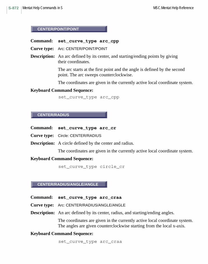
Mentat Help Commands in S MSC.Mentat Help ReferenceS-872
CENTER/POINT/POINT
Command: set_curve_type arc_cpp
Curve type: Arc: CENTER/POINT/POINT
Description: An arc defined by its center, and starting/ending points by giving their coordinates.
The arc starts at the first point and the angle is defined by the second point. The arc sweeps counterclockwise.
The coordinates are given in the currently active local coordinate system.
Keyboard Command Sequence: set_curve_type arc_cpp
CENTER/RADIUS
Command: set_curve_type arc_cr
Curve type: Circle: CENTER/RADIUS
Description: A circle defined by the center and radius.
The coordinates are given in the currently active local coordinate system.
Keyboard Command Sequence:
set_curve_type circle_cr
CENTER/RADIUS/ANGLE/ANGLE
Command: set_curve_type arc_craa
Curve type: Arc: CENTER/RADIUS/ANGLE/ANGLE
Description: An arc defined by its center, radius, and starting/ending angles.
The coordinates are given in the currently active local coordinate system. The angles are given counterclockwise starting from the local x-axis.
Keyboard Command Sequence:
set_curve_type arc_craa
CENTER/POINT/POINT
CENTER/RADIUS
CENTER/RADIUS/ANGLE/ANGLE
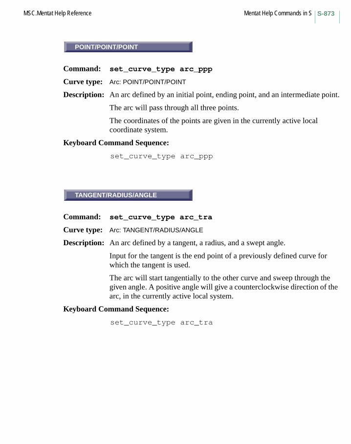
S-873MSC.Mentat Help Reference Mentat Help Commands in S
POINT/POINT/POINT
Command: set_curve_type arc_ppp
Curve type: Arc: POINT/POINT/POINT
Description: An arc defined by an initial point, ending point, and an intermediate point.
The arc will pass through all three points.
The coordinates of the points are given in the currently active local coordinate system.
Keyboard Command Sequence:
set_curve_type arc_ppp
TANGENT/RADIUS/ANGLE
Command: set_curve_type arc_tra
Curve type: Arc: TANGENT/RADIUS/ANGLE
Description: An arc defined by a tangent, a radius, and a swept angle.
Input for the tangent is the end point of a previously defined curve for which the tangent is used.
The arc will start tangentially to the other curve and sweep through the given angle. A positive angle will give a counterclockwise direction of the arc, in the currently active local system.
Keyboard Command Sequence:
set_curve_type arc_tra
POINT/POINT/POINT
TANGENT/RADIUS/ANGLE

Mentat Help Commands in S MSC.Mentat Help ReferenceS-874
BEZIER
Command: set_curve_type bezier
Curve type: BEZIER
Description: A Bezier curve defined by a list of control points.
Note that this type of curve generally, does not pass through all the control points.
Keyboard Command Sequence:
set_curve_type bezier
COMPOSITE
Command: set_curve_type composite
Curve type: COMPOSITE
Description: A curve that combines a list of curves into one single curve.
The curves to join must lie end-to-end but can be input in any order. The old curves are removed and replaced by the composite curve.
Keyboard Command Sequence:
set_curve_type composite
BEZIER
COMPOSITE
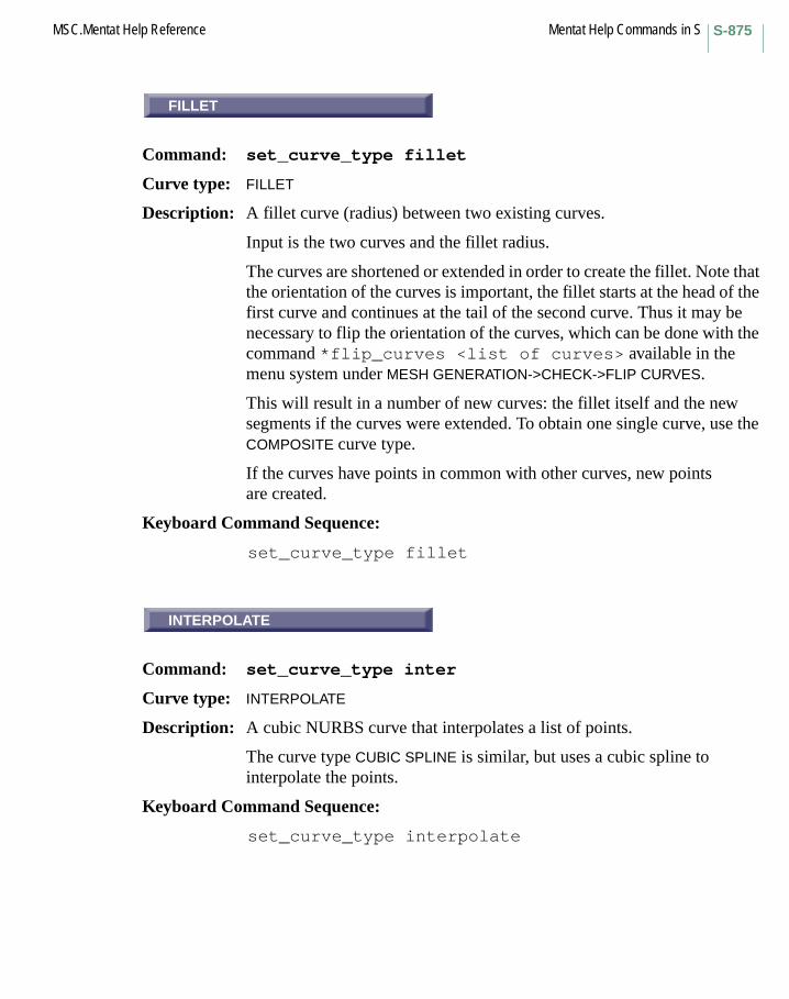
S-875MSC.Mentat Help Reference Mentat Help Commands in S
FILLET
Command: set_curve_type fillet
Curve type: FILLET
Description: A fillet curve (radius) between two existing curves.
Input is the two curves and the fillet radius.
The curves are shortened or extended in order to create the fillet. Note that the orientation of the curves is important, the fillet starts at the head of the first curve and continues at the tail of the second curve. Thus it may be necessary to flip the orientation of the curves, which can be done with the command *flip_curves <list of curves> available in the menu system under MESH GENERATION->CHECK->FLIP CURVES.
This will result in a number of new curves: the fillet itself and the new segments if the curves were extended. To obtain one single curve, use the COMPOSITE curve type.
If the curves have points in common with other curves, new points are created.
Keyboard Command Sequence:
set_curve_type fillet
INTERPOLATE
Command: set_curve_type inter
Curve type: INTERPOLATE
Description: A cubic NURBS curve that interpolates a list of points.
The curve type CUBIC SPLINE is similar, but uses a cubic spline to interpolate the points.
Keyboard Command Sequence:
set_curve_type interpolate
FILLET
INTERPOLATE

Mentat Help Commands in S MSC.Mentat Help ReferenceS-876
LINE
Command: set_curve_type line
Curve type: LINE
Description: A straight line between two points.
The line is defined by giving the end points.
Keyboard Command Sequence:
set_curve_type line
NURB
Command: set_curve_type nurb
Curve type: NURB
Description: A general NURBS curve.
The whole definition of the NURBS curve is given (NURBS – Nonuniform Rational B-Spline):
the number of control points (npoints)the curve order (order)a list of control points (npoints)a list of homogeneous coordinates (npoints)a knot vector (npoints+order)
Keyboard Command Sequence:
set_curve_type nurb
LINE
NURB

S-877MSC.Mentat Help Reference Mentat Help Commands in S
POLY LINE
Command: set_curve_type polyline
Curve type: POLY LINE
Description: A piecewise linear curve.
The curve is defined by a list of points and consists of straight line segment between these points.
Keyboard Command Sequence:
set_curve_type polyline
SAMPLED
Command: set_curve_type sampled
Curve type: SAMPLED
Description: A straight line that connects a sequence of points.
It is useful for creating curves from digitized data.
Input is the origin point of the curve and the first point (to establish the direction of the curve) and then all the points that define the curve (including selecting the origin point and the first point again).
Keyboard Command Sequence:
set_curve_type tangent
POLY LINE
SAMPLED

Mentat Help Commands in S MSC.Mentat Help ReferenceS-878
CUBIC SPLINE
Command: set_curve_type spline
Curve type: CUBIC SPLINE
Description: A cubic spline that interpolates a list of points.
The curve type INTERPOLATE is similar, but uses a more general NURBS curve to interpolate the points.
Keyboard Command Sequence:
set_curve_type spline
TANGENT
Command: set_curve_type tangent
Curve type: TANGENT
Description: A straight line that is tangent to an existing curve.
Input is an end point of an existing curve and the length of the tangent curve.
If more than one curve has this point as an end point, the curve with the lowest number will be chosen.
Keyboard Command Sequence:
set_curve_type tangent
CURVES
Command: set_curves
Description: This command toggles the drawing of curves.
Keyboard Command Sequence:
set_curves <on or off>
CUBIC SPLINE
TANGENT
CURVES
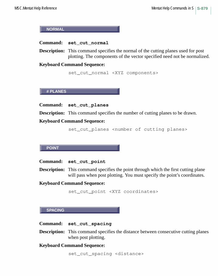
S-879MSC.Mentat Help Reference Mentat Help Commands in S
NORMAL
Command: set_cut_normal
Description: This command specifies the normal of the cutting planes used for post plotting. The components of the vector specified need not be normalized.
Keyboard Command Sequence:
set_cut_normal <XYZ components>
# PLANES
Command: set_cut_planes
Description: This command specifies the number of cutting planes to be drawn.
Keyboard Command Sequence:
set_cut_planes <number of cutting planes>
POINT
Command: set_cut_point
Description: This command specifies the point through which the first cutting plane will pass when post plotting. You must specify the point’s coordinates.
Keyboard Command Sequence:
set_cut_point <XYZ coordinates>
SPACING
Command: set_cut_spacing
Description: This command specifies the distance between consecutive cutting planes when post plotting.
Keyboard Command Sequence:
set_cut_spacing <distance>
NORMAL
# PLANES
POINT
SPACING
Mentat Help Commands in S MSC.Mentat Help ReferenceS-880
METIS BEST
Command: set_decomposition_type
Description: This button choose type of domain decomposition algorithm.
Domain decomposition is a special Marc feature that enables Marc analyses to be run in parallel on certain machines or networks. The user must divide the model into sets of elements called domains. The analysis is performed by iteratively solving systems of equations for each domain on separate CPUs and integrating the results when the solution converges.
For more information see the MSC.Marc User’s Guide or call MSC Customer Support.
Keyboard Command Sequence:
set_decomposition_type <metis_best/ metis_element_based/ metis_node_based/ geometric/ simple>
Other Buttons with the same description:
METIS ELEMENT BASEDMETIS NODE BASEDGEOMETRICSIMPLE
metis_best performs metis element based and node based decomposition, and picks the better solution.
metis_element_based performs metis element based decomposition.
metis_node_based performs metis node based decomposition.
geometric performs decomposition based on coordinates (previously domains_decompose); the algorithm tries to anneal domains.
simple performs decomposition based on ids of elements (previously domains_generate). The command renumber_elements_directed may be used to renumber the elements to help control the grouping of elements within domains.
METIS BEST

S-881MSC.Mentat Help Reference Mentat Help Commands in S
FACTOR
Command: set_defmag
Description: This command specifies the magnification of deformations when post plotting. This value is used when in manual deformation mode only (see set_automag).
Keyboard Command Sequence:
set_defmag <magnification factor>
OFF
Command: set_deformed
Description: This command specifies the mode of display of the deformed model when post plotting. The set_autmag and set_defmag commands control the degree of exaggeration of the actual deformations. You must specify whether the mode should be deformed shape only (on), deformed and undeformed shape (both), or none (off).
Keyboard Command Sequence:
set_deformed <on, off, or both>
Other Buttons with the same description:
DEF ONLYDEF & ORIG
FACTOR
OFF

Mentat Help Commands in S MSC.Mentat Help ReferenceS-882
INTERRUPTIBLE DRAWING
Command: set_draw_interrupt_onset_draw_interrupt_off
Description: These commands specify whether or not interruptible drawing is enabled. The advantage of having interruptible drawing disabled is that the model is always displayed completely drawn. However, interruptible drawing of the model makes certain Mentat features like dynamic model more user-responsive.
When interruptible drawing is ON, if the model is currently being drawn, the drawing may be interrupted at any time by new user input that would change the way the model is drawn. Thus, the user is not forced to wait for an unwanted draw of the model to complete before a more desirable draw of the model may begin.
Interruptible drawing makes it easier to correctly position a large model, using the dynamic model feature. The draw-time responsiveness may be adjusted with the draw_interrupt_time command.
By default, interruptible drawing is ON.
Also see: dynamic_model_on and draw_interrupt_time.
Keyboard Command Sequence:
set_draw_interrupt_onset_draw_interrupt_off
POINT
Command: set_duplicate_point
Description: This command sets the point about which objects will be rotated and scaled during duplication. You must specify the coordinates of the point.
Keyboard Command Sequence:
set_duplicate_point <XYZ coordinates>
INTERRUPTIBLE DRAWING
POINT

S-883MSC.Mentat Help Reference Mentat Help Commands in S
REPETITIONS
Command: set_duplicate_repetitions
Description: This command sets the number of times objects will be duplicated.
Keyboard Command Sequence:
set_duplicate_repetitions <number of repetitions>
ROTATIONS
Command: set_duplicate_rotations
Description: This command sets the amount of object rotation about the X,Y, and Z-axes during duplication. Each repetition of the duplication will rotate objects about the X, Y, and Z-axes, in that order. You must specify the angles in degrees.
Keyboard Command Sequence:
set_duplicate_rotations <X-axis rotation><Y-axis rotation> <Z-axis rotation>
SCALE FACTORS
Command: set_duplicate_scale_factors
Description: This command sets the scale factors in the X, Y, and Z-directions for duplication of objects.
Keyboard Command Sequence:
set_duplicate_scale_factors <X-direction factor><Y-direction factor> <Z-direction factor>
REPETITIONS
ROTATIONS
SCALE FACTORS
Mentat Help Commands in S MSC.Mentat Help ReferenceS-884
FROM / TO
Command: set_duplicate_trans_from_to
Description: This command sets the translation vector for duplication of objects as the displacement vector that arises when travelling from a location (FromX,FromY,FromZ) to another location (ToX,ToY,ToZ), as follows:
TX = ToX - FromXTY = ToY - FromYTZ = ToZ - FromZ
Both locations can be entered by clicking on grid points, nodes or points.
This button is located in the MESH GENERATION->DUPLICATE menu.
Keyboard Command Sequence: set_duplicate_trans_from_to
<FromX> <FromY> <FromZ><ToX> <ToY> <ToZ>
TRANSLATIONS
Command: set_duplicate_translations
Description: This command sets the translations in the X, Y, and Z-directions for duplication of objects.
Keyboard Command Sequence:
set_duplicate_translations <X-direction translation> <Y-direction translation> <Z-direction translation>
FROM / TO
TRANSLATIONS
S-885MSC.Mentat Help Reference Mentat Help Commands in S
...ATTACH INFO
Command: set_edge_attach_labels
Description: This command toggles the inclusion of attach information in the element edge labels. If switched on, the label of an attached edge includes the curve number to which the edge is attached, separated by an @-sign from the edge number.
Also see: attach_edges_curvedetach_edges
Keyboard Command Sequence: set_edge_attach_labels <on or off>
...EDGES
Command: set_edge_labels
Description: This command toggles the display of element edge labels. Edge labels are of the format element:edge.
Keyboard Command Sequence: set_edge_labels <on or off>
...EDGES
Command: set_edges
Description: This command toggles the display of element edges.
Keyboard Command Sequence: set_edges <on or off>
QUAD (4)
Command: set_element_class
Description: This command sets the element creation class (see add_elements). Available classes are as follows:
line2, line3tria3, tria6
ATTACH INFO
...EDGES
...EDGES
QUAD (4)
Mentat Help Commands in S MSC.Mentat Help ReferenceS-886
quad4, quad6, quad8, quad9tetra4, tetra10penta6, penta15hex8, hex12, hex20, hex27
Keyboard Command Sequence: set_element_class <class>
Other Buttons with the same description:HEX (12)HEX (20)HEX (27)HEX (8)LINE (2)LINE (3)PENTA (15)PENTA (6)QUAD (6)QUAD (8)QUAD (9)TETRA (10)TETRA (4)TRIA (3)TRIA (6)
ELEMENTS
Command: set_element_labels
Description: This command toggles the drawing of element labels. Labeling is only available in wireframe mode (see elements_solid, elements_wireframe).
Keyboard Command Sequence: set_element_labels <on or off>
100% SIZE
Command: set_element_size
Description: This command specifies the relative size at which elements should be displayed. If less than 100% is specified, elements will be displayed with a size less than their actual size. This feature allows you to shrink displayed elements so that other model features will be visible.
Keyboard Command Sequence: set_element_size <percent size>
ELEMENTS
100% SIZE
S-887MSC.Mentat Help Reference Mentat Help Commands in S
ELEM’S
Command: set_elements
Description: This command toggles the display of elements.
Keyboard Command Sequence: set_elements <on or off>
Another Button with the same description:ELEMENTS
INCREMENT
Command: set_expand_axito3d_upd_load
Description: With this command, the user can specify the time or the increment number at which the 3-D job starts. The load table curves are shifted based on the user input value if UPDATE LOAD TABLES button is on.
After the table curve is shifted at the origin, the time value will be zero, the apply value is the one at the user specified time if the apply is in type of load, or it will be zero if the apply is in type of displacement.
Keyboard Command Sequence:set_expand_axito3d_upd_load <on/off>
Other Buttons with the same description:TIMEUPDATE LOAD TABLES
POINT
Command: set_expand_point
Description: This command sets the point about which objects will be rotated and scaled during expansion. You must specify the coordinates of the point.
Keyboard Command Sequence: set_expand_point <XYZ coordinates>
ELEM’S
INCREMENT
POINT
Mentat Help Commands in S MSC.Mentat Help ReferenceS-888
REPETITIONS
Command: set_expand_repetitions
Description: This command sets the number of times objects will be expanded.
Keyboard Command Sequence: set_expand_repetitions <number of repetitions>
ROTATIONS
Command: set_expand_rotations
Description: This command sets the amount of object rotation about the X,Y, and Z-axes during expansion. Each repetition of the expansion will rotate objects about the X, Y, and Z-axes, in that order. You must specify the rotations in degrees.
Keyboard Command Sequence: set_expand_rotations <X-axis rotation>
<Y-axis rotation> <Z-axis rotation>
SCALE FACTORS
Command: set_expand_scale_factors
Description: This command sets the scale factors in the X, Y, and Z-directions for expansion of objects.
Keyboard Command Sequence: set_expand_scale_factors <X-direction factor>
<Y-direction factor> <Z-direction factor>
REPETITIONS
ROTATIONS
SCALE FACTORS

S-889MSC.Mentat Help Reference Mentat Help Commands in S
FROM / TO
Command: set_expand_trans_from_to
Description: This command sets the translation vector for expansion of objects as the displacement vector that arises when travelling from a location (FromX,FromY,FromZ) to another location (ToX,ToY,ToZ), as follows:
TX = ToX - FromXTY = ToY - FromYTZ = ToZ - FromZ
Both locations can be entered by clicking on grid points, nodes or points.
This button is located in the MESH GENERATION->EXPAND menu.
Keyboard Command Sequence: set_expand_trans_from_to
<FromX> <FromY> <FromZ><ToX> <ToY> <ToZ>
TRANSLATIONS
Command: set_expand_translations
Description: This command sets the translations in the X, Y, and Z-directions for expansion of objects.
Keyboard Command Sequence: set_expand_translations <X-direction translation>
<Y-direction translation> <Z-direction translation>
FROM / TO
TRANSLATIONS
Mentat Help Commands in S MSC.Mentat Help ReferenceS-890
...ATTACH INFO
Command: set_face_attach_labels
Description: This command toggles the inclusion of attach information in the element face labels. If switched on, the label of an attached face includes the surface number to which the face is attached, separated by an @-sign from the face number.
Also see: attach_faces_surfacedetach_faces
Keyboard Command Sequence: set_face_attach_labels <on or off>
...FACES
Command: set_face_labels
Description: This command toggles the display of element face labels. Face labels are of the format element:face.
Keyboard Command Sequence: set_face_labels <on or off>
...FACES
Command: set_faces
Description: This command toggles the display of element faces.
Keyboard Command Sequence: set_faces <on or off>
OK
Command: set_font
Description: This command selects the text font the program will use. This font is used for drawing text in the dialogue, menu, status, help, and graphics areas. To reset the font to the default, use the reset_font command.
Keyboard Command Sequence: set_font <font name>
ATTACH INFO
...FACES
...FACES
OK
S-891MSC.Mentat Help Reference Mentat Help Commands in S
GRID
Command: set_grid
Description: This command toggles the drawing of a grid representing the local coordinate system. Grids enable the specification of coordinates by picking gridpoints.
Keyboard Command Sequence:
set_grid <on or off>
set_grid_size
Command: set_grid_size
Description: This command sets the size of the grid, in user local coordinates u and v. The grid will range from -u_size to +u_size in the U-direction, and from -v_size to +v_size in the V-direction, where u_size and v_size are the sizes you specify.
Keyboard Command Sequence:
set_grid_size <u size> <v size>
set_grid_spacing
Command: set_grid_spacing
Description: This command sets the spacing between gridpoints. The specified values will be the spacings in the U and V-directions.
Keyboard Command Sequence:
set_grid_spacing <u spacing> <v spacing>
GRID
set_grid_size
set_grid_spacing

Mentat Help Commands in S MSC.Mentat Help ReferenceS-892
SHOW IDS
Command: set_history_increment_id
Description: This command sets step size between history point labels to the specified value. If the step size is 0, no history point labels will be displayed. If step size is 1, all labels will be displayed. If step size is 3, every third label will be displayed, etc.
Keyboard Command Sequence:
set_history_increment_id <step size>
SET NODES
set_history_nodes
Command: set_history_nodes
Description: This command specifies a list of nodes for use in history plots. You must specify a list of nodes.
Keyboard Command Sequence:
set_history_nodes <node list> #
set_history_sort
Command: set_history_sort
Description: This command instructs the program whether or not it should sort the curves in your history plot. Sorting is useful in filled mode, so that the curves will be arranged such that larger curves do not obscure smaller curves. By default, history curve sorting is ON.
Keyboard Command Sequence:
set_history_sort <on or off>
SHOW IDS
SET NODES
set_history_sort
S-893MSC.Mentat Help Reference Mentat Help Commands in S
XMAX
Command: set_history_xmax
Description: This command specifies the maximum X value to be shown in the history plot. By default, this value is one.
Keyboard Command Sequence: set_history_xmax <max x>
XMIN
Command: set_history_xmin
Description: This command specifies the minimum X value to be shown in the history plot. By default, this value is zero.
Keyboard Command Sequence: set_history_xmin <min x>
XSTEP
Command: set_history_xstep
Description: This command specifies the number of steps in X to be used in the history plot. By default, the number of steps is ten.
Keyboard Command Sequence: set_history_xstep <number of steps>
YMAX
Command: set_history_ymax
Description: This command specifies the maximum Y value to be shown in the history plot. By default, this value is one.
Keyboard Command Sequence: set_history_ymax <max y>
XMAX
XMIN
XSTEP
YMAX
Mentat Help Commands in S MSC.Mentat Help ReferenceS-894
YMIN
Command: set_history_ymin
Description: This command specifies the minimum Y value to be shown in the history plot. By default, this value is zero.
Keyboard Command Sequence:
set_history_ymin <min y>
YSTEP
Command: set_history_ystep
Description: This command specifies the number of steps in Y to be used in the history plot. By default, the number of steps is ten.
Keyboard Command Sequence:
set_history_ystep <number of steps>
HUE
Command: set_hue
Description: This command sets a range of hues between the colors of two color indices. You must specify the starting index, the ending index, and the hue value to be applied to the range. Hue is specified as a number between zero and one.
Keyboard Command Sequence:
set_hue <start index> <end index> <hue value>
YMIN
YSTEP
HUE

S-895MSC.Mentat Help Reference Mentat Help Commands in S
ENTERED VALUES
Command: set_icond_entered
Description: This command specifies that values for the current initial condition are being entered by the user (as opposed to being provided through a user subroutine; see set_icond_usersub).
Keyboard Command Sequence: set_icond_entered
INIT CONDS
Command: set_icond_labels
Description: This command toggles the display of initial condition labels.
Keyboard Command Sequence: set_icond_labels <on or off>
POST FILE
Command: set_icond_post_tape
Description: This command specifies that values for the current state variable initial condition are determined at run time by reading a previously generated post file.
Keyboard Command Sequence: set_icond_post_tape
USER SUB.
Command: set_icond_usersub
Description: This command specifies that MSC.Marc should call the appropriate user subroutine for this initial condition during the analysis. If the user subroutine has been invoked, there is no need to enter values for the application since they are ignored by MSC.Marc in lieu of the values provided by the subroutine.
ENTERED VALUES
INIT CONDS
POST FILE
USER SUB.
Mentat Help Commands in S MSC.Mentat Help ReferenceS-896
If the user subroutine is used, the FORTRAN source code file must exist in your current working directory, so that it is compiled and linked in with MSC.Marc when you submit the job (see job_usersub_file).
Keyboard Command Sequence: set_icond_usersub <on or off>
INIT CONDS
Command: set_iconds
Description: This command toggles the display of initial conditions.
Keyboard Command Sequence: set_iconds <on or off>
COLOR
Command: set_image_ps_color
Description: This command sets whether or not color should be used in subsequent PostScript plotting of image files. The alternative is gray scale.
Also see: image_save, render, and image_ps_print.
Keyboard Command Sequence: set_image_ps_color <on/off>
Another Button with the same description:GRAY
REPORT FILE
Command: set_import_report
Description: Selects the import report file.
Keyboard Command Sequence: set_import_report <report file name>
INIT CONDS
COLOR
REPORT FILE

S-897MSC.Mentat Help Reference Mentat Help Commands in S
INFO
Command: set_info_labels
Description: This command toggles the display of information labels.
Keyboard Command Sequence:
set_info_labels <on or off>
CREATE INSERTS
Command: set_insert_create
Description: This command toggles the creation of inserts during rebar meshing.
It is located in the MESH GENERATION->AUTOMESH->2D REBAR MESHING menu.
Keyboard Command Sequence:
set_insert_create <on or off>
ELEMENTS
Command: set_insert_embedded_type
Description: This command toggles the embedded entity type between elements and nodes.
It is located in the LINKS->INSERTS menu.
Keyboard Command Sequence:
set_insert_embedded_type <on or off>
Another Button with the same description:
NODES
INFO
CREATE INSERTS
ELEMENTS

Mentat Help Commands in S MSC.Mentat Help ReferenceS-898
TOLERANCE
Command: set_insert_tolerance
Description: This command sets the Exterior Tolerance for current insert. A node is considered within a host element if the distance between the element and the node is smaller than the tolerance times average edge length of the element, unless the node is actually inside another host element.
It is located in the LINKS->INSERTS menu.
Keyboard Command Sequence:set_insert_tolerance <value>
TOLERANCE
Command: set_intersect_tol
Description: This command sets the tolerance value for curve intersection checking.
Keyboard Command Sequence: set_intersect_tol
1
Command: set_light
Description: This command turns a light on or off in a view. You must specify the view and the number of the light to turn on or off. There are eight lights, numbered 1 through 8. Lighting must be ON in the view in order to see the effect.
Also see: set_lighting.
Keyboard Command Sequence: set_light <view> <light> <on or off>
Other Buttons with the same description:2 through 8LIGHT OFFLIGHT ON
TOLERANCE
TOLERANCE
1

S-899MSC.Mentat Help Reference Mentat Help Commands in S
SPOTLIGHT OFF
Command: set_light_spotlight
Description: This command sets whether or not a light is a spotlight in a view. Also, the light must be local for the spotlight characteristic to be relevant. You must specify the view and the number of the light. There are eight lights, numbered 1 through 8. Lighting and the given light must be ON, and it must be local in a view in order to see the effect.
Also see: set_lighting, set_light, light_local, light_spot_direction, and light_spot_angles.
Keyboard Command Sequence:
set_light_spotlight <view> <light> <on or off>
Another Button with the same description:
SPOTLIGHT ON
LIGHTING OFF
Command: set_lighting
Description: This command toggles the lighting feature in a view giving the model a more realistic, three-dimensional appearance. When turned ON, the default light source is from infinity, on the positive Z-axis, in view space.
Currently, lighting is implemented graphically only in the OpenGL version of Mentat.
Also see: set_light.
Keyboard Command Sequence:
set_lighting <view> <on or off>
Other Buttons with the same description:
LIGHTING ONOFFON
SPOTLIGHT OFF
LIGHTING OFF
Mentat Help Commands in S MSC.Mentat Help ReferenceS-900
ATTENUATION OFF
Command: set_lighting_attenuation
Description: This command toggles lighting attenuation in a view. Lighting attenuation is relevant when lighting is on, and it affects only the local lights in a view.
When attenuation is OFF, the strength of a local light is independent of its distance from any geometry it is illuminating.
When attenuation is ON, the strength of a local light may diminish as its distance from geometry increases.
Also see: set_lighting, lighting_attenuation, and light_local.
Keyboard Command Sequence:
set_lighting_attenuation <view> <on or off>
Another Button with the same description:
ATTENUATION ON
LIGHTNESS
Command: set_lightness
Description: This command changes the intensity of a range of colors between two color indices. You must specify the starting index, the ending index, and the lightness value to be applied to the range. Lightness is specified as a number between zero and one.
Keyboard Command Sequence:
set_lightness <start index> <end index><lightness value>
ATTENUATION OFF
LIGHTNESS
S-901MSC.Mentat Help Reference Mentat Help Commands in S
LINKS
Command: set_link_labels
Description: This command toggles the drawing of link labels.
Keyboard Command Sequence:
set_link_labels <on or off>
NUMERICAL STABILIZER
Command: spring_optionspring_multi_option
Description: If set to ON, the spring and damper force are always zeroed out and the spring only acts as a link. This can be used for both linear and nonlinear springs. In the latter case, the stabilizer flag can only be set when the stiffness option is used for the spring.
Keyboard Command Sequence:
spring_option stabilizer:on | offspring_multi_option stabilizer:on | off
LINKS
NUMERICAL STABILIZER

Mentat Help Commands in S MSC.Mentat Help ReferenceS-902
PROPERTIES
Command: spring_optionspring_multi_option
Description: This option opens a sub-window to set the electrical properties of the spring. Either linear or nonlinear springs can be defined through these commands.
Linear Spring:A linear spring with electrical conductivity E is specified through the following options – the other options can be ignored:
Nonlinear Spring:A nonlinear spring can be specified through one of two options – the conductivity option or the current option:
OR
Note: If the CURRENT option is used, use of a table with voltage as one of the independent variables is mandatory so that the table gradient can be internally calculated.
Keyboard Command Sequence:
spring_option electrical_type:conductivity | currentspring_multi_option
CONDUCTIVITY SET: E
CONDUCTIVITY SET: E TABLE: table defined as function of time, inc. no., voltage, temp. in joule heating
CURRENT SET: C TABLE: table defined as function of time, inc. no., voltage, temp. in joule heating
PROPERTIES

S-903MSC.Mentat Help Reference Mentat Help Commands in S
PROPERTIES
Command: spring_optionspring_multi_option
Description: This option opens a sub-window to set the mechanical properties of the spring. Either linear or nonlinear springs and dashpots can be defined through these commands.
NUMERICAL STABILIZER:If set to ON, the spring and damper force are always zero and the spring only acts as a link. This can be used for both linear and nonlinear springs, with the stiffness option used to define the nonlinear spring.
Linear Spring:A linear spring with stiffness K and initial force F0 is specified through the following options – the other options can be ignored:
Nonlinear Spring:A nonlinear spring can be specified through one of two options – the stiffness option or the force option:
OR
Note: If the FORCE option is used, use of a table with displacement as one of the independent variables is mandatory so that the table gradient can be internally calculated.
Linear Dashpot:A linear dashpot with damping C is specified through the following options – the other options can be ignored:
STIFFNESS SET: K
INITIAL FORCE: F0
STIFFNESS SET: K TABLE: table defined as function of time, inc. no., displacement, temp. in coupled analysis
FORCE SET: F TABLE: table defined as function of time, inc. no., displacement, temp. in coupled analysis
DAMPING COEFFICIENT SET: C
PROPERTIES

Mentat Help Commands in S MSC.Mentat Help ReferenceS-904
Nonlinear Dashpot:A nonlinear dashpot can be specified through one of two options – the coefficient option or the force option:
OR
Note: If the FORCE option is used, use of a table with velocity as one of the independent variables is mandatory so that the table gradient can be internally calculated.
Keyboard Command Sequence:
spring_option static_type:stiffness | forcespring_multi_option dynamic_type:damping | force
DAMPING COEFFICIENT SET: C TABLE: table defined as function of time, inc. no., velocity, temp. in coupled analysis
FORCE SET: C TABLE: table defined as function of time, inc. no., velocity, temp. in coupled analysis
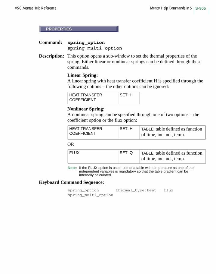
S-905MSC.Mentat Help Reference Mentat Help Commands in S
PROPERTIES
Command: spring_optionspring_multi_option
Description: This option opens a sub-window to set the thermal properties of the spring. Either linear or nonlinear springs can be defined through these commands.
Linear Spring:A linear spring with heat transfer coefficient H is specified through the following options – the other options can be ignored:
Nonlinear Spring:A nonlinear spring can be specified through one of two options – the coefficient option or the flux option:
OR
Note: If the FLUX option is used, use of a table with temperature as one of the independent variables is mandatory so that the table gradient can be internally calculated.
Keyboard Command Sequence:
spring_option thermal_type:heat | fluxspring_multi_option
HEAT TRANSFER COEFFICIENT
SET: H
HEAT TRANSFER COEFFICIENT
SET: H TABLE: table defined as function of time, inc. no., temp.
FLUX SET: Q TABLE: table defined as function of time, inc. no., temp.
PROPERTIES
Mentat Help Commands in S MSC.Mentat Help ReferenceS-906
FIXED DOF
Command: set_link_spring_typelink_multi_spring_type
Description: These commands set the type of the current spring or the type of the springs that will be created by subsequent calls to the link_multi_spring_n_to_1 and link_multi_spring_n_to_n commands. These springs can be used for mechanical, thermal, or electrical (joule) analysis. Three types are available:
1. Fixed DOF
2. To Ground
3. True Direction - only available for mechanical springs
WARNING: For coupled runs with multiple analysis passes, it is highly recommended to define mechanical, thermal, and electrical springs individually to avoid possible discrepancies in the DOF or spring types between the passes.
FIXED DOFThis is a spring that acts on selected degrees of freedom of the begin and end nodes of the spring. The force F in the spring is defined as
F = K*(ue-ub) + C*(ve-vb) + F0
where ub and ue are the displacement (or rotation) values of the degrees of freedom of the begin and end nodes, vb and ve the corresponding velocities, K and C the stiffness and damping coefficient of the spring and F0 the initial force.
TO GROUNDThis is a spring between a selected degree of freedom of a node and the fixed ground. The force F in the spring is defined as
F = K*ub + C*vb + F0
TRUE DIRECTIONThis is a true spring between the begin and end nodes. The spring acts on all displacement degrees of freedom of the nodes and the force points in the direction of the relative position of the end node with respect to the begin node of the spring. The force F in the spring is defined as
F = K*|Ue-Ub| + C*|Ve-Vb| + F0
FIXED DOF
S-907MSC.Mentat Help Reference Mentat Help Commands in S
where Ub and Ue are displacement vectors of begin and end nodes, Ve and Vb the velocities of the nodes and where |A| is the length of the vector A.
Note that the definitions given above are valid only if user subroutine USPRNG is not being used. The latter allows general nonlinear springs to be defined, in which the spring force depends in one of the three following nonlinear ways on the degrees of freedom of the begin and end nodes of the springs:
F = F( ue-ub , ve-vb ) + F0, for fixed dof springsF = F( ub , vb ) + F0, for springs to groundF = F(|Ue-Ub|,|Ve-Vb|) + F0, for true direction springs
Keyboard Command Sequence:
set_link_spring_type fixed_dof|to_ground|true_dirlink_multi_spring_type fixed_dof|to_ground|true_dir
Other Buttons with the same description:
TO GROUNDTRUE DIRECTION
USER SUBROUTINE USPRNG
Command: set_link_usersub
Description: This command enables and disables the use of the user subroutine USPRNG in Marc jobs involving links.
If the user subroutine is used, the FORTRAN source code file must exist in your current working directory, so that it can be compiled and linked in with Marc when you submit the job.
Keyboard Command Sequence:
set_link_usersub <on or off>
USER SUBROUTINE USPRNG

Mentat Help Commands in S MSC.Mentat Help ReferenceS-908
LINKS
Command: set_links
Description: This command toggles the display of links.
Keyboard Command Sequence:
set_links <yes or no>
GROUND BODY
Command: set_loadcase_ground_body
Description: This command sets the ground body for steady state rolling.Only rigid body can be selected as ground body.
Keyboard Command Sequence:
set_loadcase_ground_body <cbody>
LOADCASES
Command: set_loadcase_labels
Description: This command toggles the drawing of loadcase labels. When ON, labels of boundary conditions belonging to this loadcase are displayed.
Keyboard Command Sequence:
set_loadcase_labels <on or off>
LINKS
GROUND BODY
LOADCASES
S-909MSC.Mentat Help Reference Mentat Help Commands in S
SPINNING BODY
Command: set_loadcase_spinning_body
Description: This command sets the spinning body for steady state rolling.Only deformable body can be selected as spinning body.
Keyboard Command Sequence:
set_loadcase_spinning_body <cbody>
LOADCASES
Command: set_loadcases
Description: This command toggles the display of loadcases. When ON, boundary conditions belonging to this loadcase are displayed.
Keyboard Command Sequence:
set_loadcases <yes or no>
MATCH CURVES
Command: set_match_crvs
Description: This command toggles the match_curves parameter which tells that the command clean_surface_loops will match neighboring curves or not.
Keyboard Command Sequence:
set_match_crvs <on or off>
SPINNING BODY
LOADCASES
MATCH CURVES

Mentat Help Commands in S MSC.Mentat Help ReferenceS-910
MERGE RENUMBER
Command: set_merge_renumber
Description: This command controls the renumbering of model entities during a model merge operation. When a model is renumbered, all entities will be assigned new ids based upon their creation order. A merged model will receive higher ids than the existing model.
Keyboard Command Sequence:
set_merge_renumber <on or off>
MAX TOLERANCE
Command: set_mesh_max_tol
Description: This command sets the max. tolerance value. Max. tolerance is used for surface geometry clean. If distance between surface trimming curve points are shorter than max. tolerance, trimming curves are added to the surface.
Keyboard Command Sequence:
set_mesh_max_tol
MIN TOLERANCE
Command: set_mesh_min_tol
Description: This command sets the min. tolerance value. Min. tolerance is used as a tolerance for 2-D and 3-D geometry clean.
Keyboard Command Sequence:
set_mesh_min_tol
MERGE RENUMBER
MAX TOLERANCE
MIN TOLERANCE
S-911MSC.Mentat Help Reference Mentat Help Commands in S
SURF PARAM TOL
Command: set_mesh_param_tol
Description: This command sets the surface parametric space tolerance (param tolerance) value. Param tolerance is used for surface geometry clean.
Keyboard Command Sequence:
set_mesh_param_tol
FORMULAS
Command: set_move_formulas
Description: This command specifies the formulas used by the move commands. The variables x, y, z, are the coordinates of the node or point being moved. Also, the variable t is the polar coordinate of that node or point.
Keyboard Command Sequence:
set_move_formulas <formula x> <formula y><formula z>
POINT
Command: set_move_point
Description: This command specifies the reference point used by the move commands. You must specify the coordinates of the point.
Keyboard Command Sequence:
set_move_point <XYZ coordinates>
SURF PARAM TOL
FORMULAS
POINT

Mentat Help Commands in S MSC.Mentat Help ReferenceS-912
ROTATIONS
Command: set_move_rotations
Description: This command specifies the amount of rotation about the X, Y, and Z-axes performed by move commands.
Keyboard Command Sequence: set_move_rotations <X-axis rotation>
<Y-axis rotation> <Z-axis rotation>
SCALE FACTORS
Command: set_move_scale_factors
Description: This command sets the scale factors in the X, Y, and Z-directions used by the move commands.
Keyboard Command Sequence: set_move_scale_factors <X-direction factor>
<Y-direction factor> <Z-direction factor>
FROM / TO
Command: set_move_trans_from_to
Description: This command sets the translation vector for moving of objects as the displacement vector that arises when travelling from a location (FromX,FromY,FromZ) to another location (ToX,ToY,ToZ), as follows:
TX = ToX - FromXTY = ToY - FromYTZ = ToZ - FromZ
Both locations can be entered by clicking on grid points, nodes or points.
This button is located in the MESH GENERATION->MOVE menu.
Keyboard Command Sequence: set_move_trans_from_to <FromX> <FromY> <FromZ> <ToX> <ToY> <ToZ>
ROTATIONS
SCALE FACTORS
FROM / TO

S-913MSC.Mentat Help Reference Mentat Help Commands in S
TRANSLATIONS
Command: set_move_translations
Description: This command specifies the amount of translation in the X, Y, and Z-directions performed by move commands.
Keyboard Command Sequence: set_move_translations <X-axis translation>
<Y-axis translation> <Z-axis translation>
ATTACH INFO
Command: set_node_attach_labels
Description: This command toggles the inclusion of attach information in the element node labels. If switched on, the label of an attached node includes the point number to which the node is attached, separated by an @-sign from the node number.
Also see: attach_nodes_pointdetach_nodes
Keyboard Command Sequence: set_node_attach_labels <on or off>
NODES
Command: set_node_labels
Description: This command toggles the display of node ids.
Keyboard Command Sequence: set_node_labels <yes or no>
TRANSLATIONS
ATTACH INFO
NODES

Mentat Help Commands in S MSC.Mentat Help ReferenceS-914
NODES
Command: set_nodes
Description: This command toggles the display of nodes.
Keyboard Command Sequence: set_nodes <yes or no>
XMAX
Command: set_opt_plot_xmax
Description: This command specifies the maximum X value to be shown in the response gradient plot. By default, this value is one.
Keyboard Command Sequence: set_opt_plot_xmax <max x>
XMIN
Command: set_opt_plot_xmin
Description: This command specifies the minimum X value to be shown in the response gradient plot. By default, this value is zero.
Keyboard Command Sequence: set_opt_plot_xmin <min x>
XSTEP
Command: set_opt_plot_xstep
Description: This command specifies the number of steps in X to be used in the response gradient plot. By default, the number of steps is ten.
Keyboard Command Sequence: set_opt_plot_xstep <number of steps>
NODES
XMAX
XMIN
XSTEP

S-915MSC.Mentat Help Reference Mentat Help Commands in S
YMAX
Command: set_opt_plot_ymax
Description: This command specifies the maximum Y value to be shown in the response gradient plot. By default, this value is one.
Keyboard Command Sequence:
set_opt_plot_ymax <max y>
YMIN
Command: set_opt_plot_ymin
Description: This command specifies the minimum Y value to be shown in the response gradient plot. By default, this value is zero.
Keyboard Command Sequence:
set_opt_plot_ymin <min y>
YSTEP
Command: set_opt_plot_ystep
Description: This command specifies the number of steps in Y to be used in the response gradient plot. By default, the number of steps is ten.
Keyboard Command Sequence:
set_opt_plot_ystep <number of steps>
YMAX
YMIN
YSTEP

Mentat Help Commands in S MSC.Mentat Help ReferenceS-916
ANGLE
Command: set_orient_angle
Description: This command sets the orientation angle for the current orientation. The orientation angle is required for all orientation types.
Note that this command is not allowed for orientation type 3d_aniso. The command orient_rotate should be used instead.
Keyboard Command Sequence:
set_orient_angle <angle in degrees>
ORIENTS
Command: set_orient_labels
Description: This command toggles the display of element orientation labels.
Keyboard Command Sequence:
set_orient_labels <on or off>
VECTOR 1
Command: set_orient_vector1
Description: This command sets the first user-defined vector for the current orientation. The first user-defined vector is required for orientation types xu_plane, yu_plane, zu_plane, uu_plane, and 3d_aniso.
Keyboard Command Sequence:
set_orient_vector1 <X, Y, Z vector coordinates>
ANGLE
ORIENTS
VECTOR 1
S-917MSC.Mentat Help Reference Mentat Help Commands in S
VECTOR 2
Command: set_orient_vector2
Description: This command sets the second user-defined vector for the current orientation. The second user-defined vector is required for orientation types uu_plane and 3d_aniso.
Keyboard Command Sequence:
set_orient_vector2 <X, Y, Z vector coordinates>
ORIENTS
Command: set_orients
Description: This command toggles the display of element orientations.
Keyboard Command Sequence:
set_orients <on or off>
BIAS FACTORS
Command: set_overlay_bias_factors
Description: This command sets the bias factors used by the overlay_mesh command. Bias factors are numbers between -1 and 1. Positive bias factors skew element creation locations in the positive direction, i.e. more entities are created in the positive direction. Negative bias factors skew element creation locations in the negative direction. Biasing is parabolic. Zero factors produce evenly distributed elements.
Singularities may occur if the magnitude of the bias factor is greater than one third.
Keyboard Command Sequence:
set_overlay_bias_factors <U-direction factor><V-direction factor>
VECTOR 2
ORIENTS
BIAS FACTORS
Mentat Help Commands in S MSC.Mentat Help ReferenceS-918
DIVISIONS
Command: set_overlay_divisions
Description: This command sets the number of divisions used by the overlay_mesh command, i.e. the number of elements created in each direction.
Keyboard Command Sequence:
set_overlay_divisions <number in U-direction><number in V-direction>
SHOW IDS
Command: set_pathplot_node_id
Description: This command sets step size between path plot node labels to the specified value.
If the step size is 0, no path plot node labels will be displayed.If step size is 1, all labels will be displayed.If step size is 3, every third label will be displayed, etc.
Keyboard Command Sequence:
set_pathplot_node_id <step size>
NODE PATH
Command: set_pathplot_path
Description: This command specifies a path of nodes for use in path plots. You must specify a group of nodes in the order that you wish them to appear in the path plot.
Keyboard Command Sequence:
set_pathplot_path <nodes> #
DIVISIONS
SHOW IDS
NODE PATH

S-919MSC.Mentat Help Reference Mentat Help Commands in S
set_pathplot_sort
Command: set_pathplot_sort
Description: This command instructs the program whether or not it should sort the curves in your path plot. Sorting is useful in filled mode, so that the curves are arranged such that larger curves do not obscure smaller curves. By default, path plot curve sorting is ON.
Keyboard Command Sequence:
set_pathplot_sort <on or off>
XMAX
Command: set_pathplot_xmax
Description: This command specifies the maximum X value to be shown in the path plot. By default, this value is one.
Keyboard Command Sequence:
set_pathplot_xmax <max x>
XMIN
Command: set_pathplot_xmin
Description: This command specifies the minimum X value to be shown in the path plot. By default, this value is zero.
Keyboard Command Sequence:
set_pathplot_xmin <min x>
set_pathplot_sort
XMAX
XMIN
Mentat Help Commands in S MSC.Mentat Help ReferenceS-920
XSTEP
Command: set_pathplot_xstep
Description: This command specifies the number of steps in X to be used in the path plot. By default, the number of steps is ten.
Keyboard Command Sequence: set_pathplot_xstep <number of steps>
YMAX
Command: set_pathplot_ymax
Description: This command specifies the maximum Y value to be shown in the path plot. By default, this value is one.
Keyboard Command Sequence: set_pathplot_ymax <max y>
YMIN
Command: set_pathplot_ymin
Description: This command specifies the minimum Y value to be shown in the path plot. By default, this value is zero.
Keyboard Command Sequence: set_pathplot_ymin <min y>
YSTEP
Command: set_pathplot_ystep
Description: This command specifies the number of steps in Y to be used in the path plot. By default, the number of steps is ten.
Keyboard Command Sequence: set_pathplot_ystep <number of steps>
PLANE TOL.
XSTEP
YMAX
YMIN
YSTEP
PLANE TOL.
S-921MSC.Mentat Help Reference Mentat Help Commands in S
Command: set_plane_tol
Description: This command sets the angular tolerance used by the plane select method.
Keyboard Command Sequence:
set_plane_tol <tolerance>
POINTS
Command: set_point_labels
Description: This command toggles the display of point ids.
Keyboard Command Sequence:
set_point_labels <on or off>
POINTS
Command: set_points
Description: This command toggles the display of points.
Keyboard Command Sequence:
set_points <on or off>
DELTA
Command: set_post_delta
Description: This command toggles the difference results plotting feature, which when turned on plots the difference of the current increment with the previously plotted increment.
Keyboard Command Sequence:
set_post_delta <on/off>
POINTS
POINTS
DELTA
Mentat Help Commands in S MSC.Mentat Help ReferenceS-922
POST PROCEDURE
Command: set_post_procedure
Description: This command toggles the post_procedure_file feature, which when turned on will execute the contents of a procedure file at each increment.
Also see help: post_procedure_file
Keyboard Command Sequence:set_post_procedure <on/off>
USE NODAL TRANSFORMATIONS
Command: set_tform_nqs
Description: This command toggles the transformation of nodal quantities during the post processing of MSC.Marc post files. By default, nodal quantities are displayed in the global coordinate system. If this option is on, the nodal transformations that exist on the post file are applied.
Keyboard Command Sequence: set_tform_nqs <on/off>
USER TENSORS
Command: set_post_user_tensors
Description: This command toggles the plotting of user defined tensors. User tensors are available when all six components of a normal tensor are available as user defined post variables. When user tensors are turned on, the additional tensor scalars and vectors will be computed from the user defined tensor and be made available for plotting.
Keyboard Command Sequence: set_post_user_tensors <on/off>
POST PROCEDURE
USE NODAL TRANSFORMATIONS
USER TENSORS

S-923MSC.Mentat Help Reference Mentat Help Commands in S
set_proc_echo
Command: set_proc_echo
Description: This command toggles procedure command echoing. When executing a procedure with procedure echo on, commands are echoed in the dialogue area as they are executed.
Keyboard Command Sequence:
set_proc_echo <on or off>
COEF.
Command: set_rbe3_ret_coef_def
Description: This command in the RBE3 menu sets the default coefficient for retained nodes.
Keyboard Command Sequence:
set_rbe3_ret_coef_def <coefficient>
1
Command: set_rbe3_ret_dof_def
Description: This command in the RBE3 menu sets the default dof for retained nodes.
Keyboard Command Sequence:
set_rbe3_ret_dof_def <dof_id>
Other buttons with the same description:
2, 3, 4, 5, and 6
set_proc_echo
COEF.
1

Mentat Help Commands in S MSC.Mentat Help ReferenceS-924
TOLERANCE
Command: set_relative_tol
Description: This tolerance parameter is used as a relative tolerance for geometry repair and meshing. The absolute relative value is computed by multiplying the relative tolerance value by the curve length.
Keyboard Command Sequence:
set_relative_tol
TOLERANCE
Command: set_relax_tolerance
Description: This command sets the convergence tolerance used by the relax_nodes command.
Keyboard Command Sequence:
set_relax_tolerance <tolerance>
ANTI-ALIASING
Command: set_render_antialias
Description: This command sets antialiasing on or off for subsequent rendered images. Antialiasing is a technique which attempts to minimize the jaggedness and other unwanted artifacts that sometimes appear in raster images. Images generally look better with antialiasing turned on, but they may take longer to create.
Also see: render, render_antialias_tol, and render_antialias_depth.
Keyboard Command Sequence:
set_render_antialias <on/off>
TOLERANCE
TOLERANCE
ANTI-ALIASING

S-925MSC.Mentat Help Reference Mentat Help Commands in S
HIGHLIGHTS
Command: set_render_highlights
Description: This command sets highlights on or off for subsequent rendered images. Specular highlights can appear on shiny materials, where they reflect a light source. This command sets whether or not such highlights are included in rendered images.
Also see: render, render_standard, and set_render_shadows.
Keyboard Command Sequence: set_render_highlights <on/off>
SHADOWS
Command: set_render_shadows
Description: This command sets shadows on or off for subsequent rendered images. Shadows can appear wherever a material blocks a light source. This command sets whether or not shadows are included in rendered images. Images generally look better with shadows turned on, but they may take longer to create.
Also see: render, render_standard, and set_render_highlights.
Keyboard Command Sequence: set_render_shadows <on/off>
INCREMENT
Command: set_renumber_increment
Description: This command specifies the amount by which each new id number is incremented when entities are renumbered.
Keyboard Command Sequence: set_renumber_increment <increment>
HIGHLIGHTS
SHADOWS
INCREMENT
Mentat Help Commands in S MSC.Mentat Help ReferenceS-926
ELEMENTS
Command: set_renumber_start
Description: This command sets the first id to be used by the renumber commands.
Keyboard Command Sequence:
set_renumber_start <initial id>
Other Buttons with the same description:
ELEMS DIRECTEDNODESSTART
REMOVE FREE CURVES
Command: set_rm_free_crvs
Description: This command toggles the rm_free_curves parameter which tells that the command clean_surface_loops will remove free curves or not.
Keyboard Command Sequence:
set_rm_free_crvs <on or off>
SATURATION
Command: set_saturation
Description: This command changes the saturation of a range of colors between two color indices. You must specify the starting index, the ending index, and the saturation value to be applied to the range. Saturation is specified as a number between zero and one.
Keyboard Command Sequence:
set_saturation <start index> <end index><saturation value>
ELEMENTS
REMOVE FREE CURVES
SATURATION

S-927MSC.Mentat Help Reference Mentat Help Commands in S
set_save_as_version
Command: set_save_as_version
Description: This command specifies the format of the model file. It only affects the save_as_model (SAVE AS) command.
Keyboard Command Sequence:
set_save_as_version <default|ment330|ment320|ment310|ment231>
set_save_formatted
Command: set_save_formatted
Description: This command sets the format of database files created with the save model commands. Formatted database files are ascii text files, and are editable and portable across machine architectures. Unformatted (binary) database files are not always architecture independent but are smaller and processed more quickly.
Keyboard Command Sequence: set_save_formatted <on or off>
SELECT DISTANCE
Command: set_select_distance
Description: This command sets the select distance for selecting items that fall within a certain distance of a point, curve or surface by the select_method_point_dist, select_method_curve_dist, and select_method_surface_dist methods.
This button is located under the UTILS->SELECT->METHOD menu.
Keyboard Command Sequence: set_select_distance
set_save_as_version
set_save_formatted
SELECT DISTANCE

Mentat Help Commands in S MSC.Mentat Help ReferenceS-928
...EDGES
Command: set_solid_edge_labels
Description: This command toggles the labeling of solid edges with their ids.
Keyboard Command Sequence:
set_solid_edge_labels <on or off>
...EDGES
Command: set_solid_edges
Description: This command toggles the drawing of solid edges.
Keyboard Command Sequence: set_solid_edges <on or off>
...FACES
Command: set_solid_face_labels
Description: This command toggles the labeling of solid faces with their ids.
Keyboard Command Sequence: set_solid_face_labels <on or off>
NORMAL DEV.
Command: set_face_normal_dev
Description: This command will set the maximum deviation allowed between 2 normals for adjacent facets generated for the displaying of the solid surface.
Keyboard Command Sequence:set_solid_face_surface_dev <value>
...EDGES
...EDGES
...FACES
NORMAL DEV.
S-929MSC.Mentat Help Reference Mentat Help Commands in S
SURFACE DEV.
Command: set_face_surface_dev
Description: This command will set the allowed value for offset distance from the facets generated for display to the actual solid surface.
Keyboard Command Sequence:set_solid_face_surface_dev <value>
...FACES
Command: set_solid_faces
Description: This command toggles the drawing of solid faces.
Keyboard Command Sequence: set_solid_faces <on or off>
SOLIDS
Command: set_solid_labels
Description: This command toggles the labeling of solids with their ids.
Keyboard Command Sequence: set_solid_labels <on or off>
BLOCK
Command: set_solid_type
Description: This command sets the solid create type to the specified type. Subsequent add_solids commands will create solids of this type. Available solid types are as follows:
block spherecylinder torusprism
Keyboard Command Sequence: set_solid_type <type>
SURACE DEV.
...FACES
SOLIDS
BLOCK

Mentat Help Commands in S MSC.Mentat Help ReferenceS-930
Other Buttons with the same description:CYLINDERPRISMSPHERETORUS
...VERTICES
Command: set_solid_vertex_labels
Description: This command toggles the labeling of solid vertices with their ids.
Keyboard Command Sequence:
set_solid_vertex_labels <on or off>
...VERTICES
Command: set_solid_vertices
Description: This command toggles the drawing of solid vertices.
Keyboard Command Sequence:
set_solid_vertices <on or off>
SOLIDS
Command: set_solids
Description: This command toggles the drawing of solids.
Keyboard Command Sequence:
set_solids <on or off>
...VERTICES
...VERTICES
SOLIDS
S-931MSC.Mentat Help Reference Mentat Help Commands in S
set_surface_divisions
Command: set_surface_divisions
Description: This command sets the number of divisions in each direction to be used when drawing surfaces. The more number of divisions, the more realistic surfaces will appear.
Keyboard Command Sequence:
set_surface_divisions <number of divisions>
SURFACES
Command: set_surface_labels
Description: This command toggles the labeling of surfaces with their ids.
Keyboard Command Sequence:
set_surface_labels <on or off>
LINES
Command: set_surface_lines
Description: This command specifies that surfaces edges should be drawn when in surfaces_solid mode.
Keyboard Command Sequence:
set_surface_lines <on or off>
set_surface_divisions
SURFACES
LINES
Mentat Help Commands in S MSC.Mentat Help ReferenceS-932
SURFACE TYPE
Menu: SURFACE TYPE
Description: This button toggles the type of surface to create. Subsequent add_surfaces commands will create surfaces of this type. Available surface types are as follows:
QUAD A bilinear surface defined by four corner points.
BEZIER A bezier surface defined by a list of control points.
DRIVEN A surface defined by a driven driving curve.
NURB A general NURBS surface given by a complete definition: the number of control points in each direction, the curve order in each direction, a list of control points, a list of homogeneous coordinates, and a knot vector.
RULED A linear surface between two curves.
SPHERE A sphere by giving the center and radius.
CYLINDER A cylindrical (or conical) surface.
SWEPT A surface defined by a swept curve, a sweeping curve, and the number of steps.
INTERPOLATE A cubic NURBS surface that interpolates npu*npv control points.
COONS Coons linear surface defined by four boundary curves.
SKIN Smooth curve passing through a list of curves.
SAMPLED A surface created by a sequence of points. It is useful for creating surfaces from digitized data. Input is the origin point of the surface, a point in the first direction (to establish the first direction of the surface), then a point in the second direction of the surface (to establish the second direction of the surface), and then all the points that will define the surface (including selecting the origin point and the points in the first and second directions again).
SURFACE TYPE

S-933MSC.Mentat Help Reference Mentat Help Commands in S
BEZIER
Command: set_surface_type bezier
Surface Type: BEZIER
Description: A Bezier surface defined by a list of control points.
Note that this type of surface does in general not pass through all the control points.
Input is the point numbers (not the coordinates).
Keyboard Command Sequence:
set_surface_type bezier
COONS
Command: set_surface_type coons
Surface Type: COONS
Description: A Coons (linear) surface is defined by four boundary curves.
It can be described as a combination of two ruled surfaces, defined by the opposite sides.
The four curves must be given in cyclic order around the boundary.
Note that the orientation of the curves is important. They must be placed head-to-tail. Thus, it may be necessary to flip some of the curves, which can be done with the command
*flip_curves <list of curves>
available in the menu system under
MESH GENERATION->CHECK->FLIP CURVES
Keyboard Command Sequence:
set_surface_type coons
BEZIER
COONS

Mentat Help Commands in S MSC.Mentat Help ReferenceS-934
CYLINDER
Command: set_surface_type cylinder
Surface Type: CYLINDER
Description: A cylinder (or actually a cone) defined by two points on the axis and the radii at these points.
Input is the coordinates of the points on the axis (not point numbers).
Keyboard Command Sequence:
set_surface_type cylinder
DRIVEN
Command: set_surface_type driven
Surface Type: DRIVEN
Description: A driven surface is defined by a driven and driving curve.
The surface is generated by moving the driven curve along the driving curve.
The driving curve can be positioned anywhere in space. Thus, a translation of the driving curve does not affect the generated surface.
A surface of revolution can be created by using a circle appropriately oriented as a driving curve.
Keyboard Command Sequence:
set_surface_type driven
CYLINDER
DRIVEN
S-935MSC.Mentat Help Reference Mentat Help Commands in S
INTERPOLATE
Command: set_surface_type interpolate
Surface Type: INTERPOLATE
Description: A cubic NURBS surface that interpolates a list of points.
Input is the number of points in the u- and v-direction and the points. The points (point numbers, not coordinates) are given column wise, i.e. first by looping over rows.
Keyboard Command Sequence: set_surface_type interpolate
NURB
Command: set_surface_type nurb
Surface Type: NURB
Description: A general NURBS surface.
The whole definition of the NURBS surface is given (NURBS – Nonuniform Rational B-Spline):
Keyboard Command Sequence: set_surface_type nurb
the number of control points in u-direction
(npu)
the number of control points in v-direction
(npv)
the curve order in u-direction (ordu)
the curve order in v-direction (ordv)
a list of control points (npu*npv)
a list of homogeneous coordinates
(npu*npv)
a knot vector (npu+ordu+npv+ordv)
INTERPOLATE
NURB

Mentat Help Commands in S MSC.Mentat Help ReferenceS-936
QUAD
Command: set_surface_type quad
Surface Type: QUAD
Description: A bilinear surface defined by four corner points.
Input is the point numbers (not the coordinates).
Keyboard Command Sequence:
set_surface_type quad
RULED
Command: set_surface_type ruled
Surface Type: RULED
Description: A ruled surface is defined by two curves. The surface can be described as generated by a straight line that is connected to the starting ends of the two curves and moved along them.
Note that the orientation of the defining curves is important. It may be necessary to flip one of the curves, which can be done with the command
*flip_curves <list of curves>
available in the menu system under
MESH GENERATION->CHECK->FLIP CURVES
Keyboard Command Sequence:
set_surface_type ruled
QUAD
RULED
S-937MSC.Mentat Help Reference Mentat Help Commands in S
SAMPLED
Command: set_surface_type sampled
Surface Type: SAMPLED
Description: A surface created by a sequence of points.
It is useful for creating surfaces from digitized data. Input is the origin point of the surface, a point in the first direction (to establish the first direction of the surface), then a point in the second direction of the surface (to establish the second direction of the surface), and then all the points that will define the surface (including selecting the origin point and the points in the first and second directions again).
Keyboard Command Sequence:
set_surface_type sampled
SKIN
Command: set_surface_type skin
Surface Type: SKIN
Description: A skinned surface is defined by a list of curves.
The surface passes through all curves producing a smooth surface. If only two curves are given, it gives a ruled surface.
Note that the orientation of the defining curves is important. It may be necessary to flip some of the curves, which can be done with the command
*flip_curves <list of curves>
available in the menu system under
MESH GENERATION->CHECK->FLIP CURVES
Keyboard Command Sequence:
set_surface_type skin
SAMPLED
SKIN
Mentat Help Commands in S MSC.Mentat Help ReferenceS-938
SPHERE
Command: set_surface_type sphere
Surface Type: SPHERE
Description: A sphere defined by the center and the radius.
Input is the coordinates of the center point (not a point number).
Keyboard Command Sequence:
set_surface_type sphere
SWEPT
Command: set_surface_type swept
Surface Type: SWEPT
Description: A swept surface is defined by a swept curve, a sweeping curve, and the number of steps in the surface.
Keyboard Command Sequence:
set_surface_type swept
SURF’S
Command: set_surfaces
Description: This command toggles the drawing of surfaces.
Keyboard Command Sequence:
set_surfaces <on or off>
Another Button with the same description:
SURFACES
SPHERE
SWEPT
SURF’S

S-939MSC.Mentat Help Reference Mentat Help Commands in S
GLOBAL
Command: set_surfint_space
Description: This command controls the construction of the space curve during surface/surface intersection.
Keyboard Command Sequence:
set_surfint_space <on/off>
TRIM 1
Command: set_surfint_trim1
Description: This command controls the construction of the trimming curve for the first surface during surface/surface intersection.
Keyboard Command Sequence:
set_surfint_trim1 <on/off>
TRIM 2
Command: set_surfint_trim2
Description: This command controls the construction of the trimming curve for the second surface during surface/surface intersection.
Keyboard Command Sequence:
set_surfint_trim2 <on/off>
TOLERANCE
GLOBAL
TRIM 1
TRIM 2
TOLERANCE

Mentat Help Commands in S MSC.Mentat Help ReferenceS-940
Command: set_sweep_tolerance
Description: This command sets the tolerance to be used by the sweep commands in determining coincident entities.
Keyboard Command Sequence: set_sweep_tolerance <tolerance>
NORMAL
Command: set_symmetry_normal
Description: This command specifies a normal which, along with a point set by the set_symmetry_point command, defines a plane about which entities are duplicated by the symmetry duplication commands.
Keyboard Command Sequence: set_symmetry_normal <X component> <Y component>
<Z component>
FROM / TO
Command: set_symmetry_plane_normal_from_to
Description: This command sets the normal vector of the plane about which entities are reflected by the symmetry commands as the normalized displacement vector that arises when travelling from a location (FromX,FromY,FromZ) to another location (ToX,ToY,ToZ), as follows:
NX = ToX - FromXNY = ToY - FromYNZ = ToZ - FromZ
Both locations can be entered by clicking on grid points, nodes or points.
This button is located in the MESH GENERATION->SYMMETRY menu.
Keyboard Command Sequence: set_symmetry_plane_normal_from_to
<FromX> <FromY> <FromZ><ToX> <ToY> <ToZ>
NORMAL
FROM / TO
S-941MSC.Mentat Help Reference Mentat Help Commands in S
POINT
Command: set_symmetry_point
Description: This command specifies a point which, along with a normal set by the set_symmetry_normal command, defines a plane about which entities are duplicated by the symmetry duplication commands.
Keyboard Command Sequence:
set_symmetry_point <X coordinate> <Y coordinate><Z coordinate>#END
SHOW IDS
Command: set_table_point_id
Description: This command sets step size between table point labels to the specified value.
If the step size is 0, no table point labels will be displayed.If step size is 1, all labels will be displayed.If step size is 3, every third label will be displayed, etc.
Keyboard Command Sequence:
set_table_point_id <step size>
POINT
SHOW IDS
Mentat Help Commands in S MSC.Mentat Help ReferenceS-942
OK
Command: set_table_type
Description: This command sets the type of the current table to the specified type. The type of information conveyed by a table makes the table accessible to the analysis code for various purposes. The valid table types are as follows:
nonetimetemperaturedensityplastic_strainstressstrain_ratestress_rate
Keyboard Command Sequence:
set_table_type <type>
XMAX
Command: set_table_xmax
Description: This command specifies the maximum X value to be shown in the table. By default, this value is one.
Keyboard Command Sequence:
set_table_xmax <max x>
OK
XMAX

S-943MSC.Mentat Help Reference Mentat Help Commands in S
XMIN
Command: set_table_xmin
Description: This command specifies the minimum X value to be shown in the table. By default, this value is zero.
Keyboard Command Sequence:
set_table_xmin <min x>
X-AXIS
Command: set_table_xname
Description: This command specifies a name for the x-axis of the current table.
Keyboard Command Sequence:
set_table_xname <name>
XSTEP
Command: set_table_xstep
Description: This command specifies the number of steps in X to be used in the table. By default, the number of steps is ten.
Keyboard Command Sequence:
set_table_xstep <number of steps>
XMIN
X-AXIS
XSTEP
Mentat Help Commands in S MSC.Mentat Help ReferenceS-944
YMAX
Command: set_table_ymax
Description: This command specifies the maximum Y value to be shown in the table. By default, this value is one.
Keyboard Command Sequence:
set_table_ymax <max y>
YMIN
Command: set_table_ymin
Description: This command specifies the minimum Y value to be shown in the table. By default, this value is zero.
Keyboard Command Sequence:
set_table_ymin <min y>
Y-AXIS
Command: set_table_yname
Description: This command specifies a name for the y-axis of the current table.
Keyboard Command Sequence:
set_table_yname <name>
YMAX
YMIN
Y-AXIS
S-945MSC.Mentat Help Reference Mentat Help Commands in S
YSTEP
Command: set_table_ystep
Description: This command specifies the number of steps in Y to be used in the table. By default, the number of steps is ten.
Keyboard Command Sequence:
set_table_ystep <number of steps>
set_tetmesh_aspect
Command: set_tetmesh_aspect
Description: This command sets the desired aspect ratio when automatically meshing with tetrahedrals. The aspect ratio is defined such that a value of one is the ideal shape for an element. Values greater than one indicate that elements of less than ideal aspect ratios are allowed.
Keyboard Command Sequence:
set_tetmesh_aspect <aspect ratio>
TRIM BARE SURFACES
Command: set_trim_surfs
Description: This command toggles the trim_surfaces parameter which tells that the command clean_surface_loops will trim bare surfaces or not.
Keyboard Command Sequence:
set_trim_surfs <on or off>
YSTEP
set_tetmesh_aspect
TRIM BARE SURFACES
Mentat Help Commands in S MSC.Mentat Help ReferenceS-946
set_trimesh_aspect
Command: set_trimesh_aspect
Description: This command sets the desired aspect ratio when automatically meshing with triangles. The aspect ratio is defined such that a value of one is the ideal shape for an element. Values greater than one indicate that elements of less than ideal aspect ratios are allowed.
Keyboard Command Sequence:
set_trimesh_aspect <aspect ratio>
UNDO
Command: set_undo
Description: This command toggles the undo feature. When undo is enabled, the user may undo the last operation which changed the model (including a previous undo).
Keyboard Command Sequence:
set_undo <on or off>
FACTOR
Command: set_vecmag
Description: This command sets the vector magnification to be used in a post vector plot.
Keyboard Command Sequence:
set_vecmag <magnification factor>
set_trimesh_aspect
UNDO
FACTOR
S-947MSC.Mentat Help Reference Mentat Help Commands in S
set_view_repeat
Command: set_view_repeat
Description: This command toggles view change repeat mode. When OFF, commands that cause the view to change (e.g. rot_x_for) execute just once. With repeat mode ON, these commands execute repeatedly, until stopped with a mouse-click or keystroke. By default, view change repeat is OFF. Use the command set_view_repeat_pause to set the pause between command executions.
Keyboard Command Sequence:
set_view_repeat <on or off>
REPEAT PAUSE
Command: set_view_repeat_pause
Description: This command specifies the number of seconds to pause between frames when view change repeat mode is ON. By default, this number is zero.
Keyboard Command Sequence:
set_view_repeat_pause <number of seconds>
SHOW IDS
Command: set_xcurve_increment_id
Description: This command sets the number of (x,y) points/increment label.
Keyboard Command Sequence:
set_xcurve_increment_id <value>
set_view_repeat
REPEAT PAUSE
SHOW IDS
Mentat Help Commands in S MSC.Mentat Help ReferenceS-948
TITLE
Command: set_xcurve_title
Description: This command sets the title to the experimental data plot.
Keyboard Command Sequence:
set_xcurve_title <title>
XMAX
Command: set_xcurve_xmax
Description: This command sets the right bound for the abscissa.
Keyboard Command Sequence:
set_xcurve_xmax <value>
XMIN
Command: set_xcurve_xmin
Description: This command sets the left bound for the abscissa.
Keyboard Command Sequence:
set_xcurve_xmin <value>
X-AXIS
Command: set_xcurve_xname
Description: This command sets the label to the abscissa.
Keyboard Command Sequence:
set_xcurve_xname <label>
TITLE
XMAX
XMIN
X-AXIS

S-949MSC.Mentat Help Reference Mentat Help Commands in S
XSTEP
Command: set_xcurve_xstep
Description: This command sets the number gridlines/gridlabel in the abscissa.
Keyboard Command Sequence:
set_xcurve_xstep <value>
YMAX
Command: set_xcurve_ymax
Description: This command sets the upper bound for the ordinate.
Keyboard Command Sequence:
Command: set_xcurve_ymax <value>
YMIN
Command: set_xcurve_ymin
Description: This command sets the lower bound for the ordinate.
Keyboard Command Sequence:
set_xcurve_ymin <value>
Y-AXIS
Command: set_xcurve_yname
Description: This command sets the label to the ordinate.
Keyboard Command Sequence:
set_xcurve_yname <label>
XSTEP
YMAX
YMIN
Y-AXIS
Mentat Help Commands in S MSC.Mentat Help ReferenceS-950
YSTEP
Command: set_xcurve_ystep
Description: This command sets the number gridlines/gridlabel in the ordinate.
Keyboard Command Sequence:set_xcurve_ystep <value>
NAME
Command: set_xy_plot_curve_name
Description: This command sets the name of a curve to be used in the legend of the plot.
Keyboard Command Sequence: set_xy_plot_curve_name <curve> <name>
SHOW IDS
Command: set_xy_plot_point_id
Description: This command sets step size between plot point labels to the specified value.
If the step size is 0, no plot point labels will be displayed.If step size is 1, all labels will be displayed.If step size is 3, every third label will be displayed, etc.
Keyboard Command Sequence: set_xy_plot_point_id <step size>
TITLE
Command: set_xy_plot_title
Description: This command sets the title of the plot.
Keyboard Command Sequence: set_xy_plot_title <title>
YSTEP
NAME
SHOW IDS
TITLE
S-951MSC.Mentat Help Reference Mentat Help Commands in S
XMAX
Command: set_xy_plot_xmax
Description: This command specifies the maximum X value to be shown in the plot. By default, this value is one.
Keyboard Command Sequence:
set_xy_plot_xmax <max x>
XMIN
Command: set_xy_plot_xmin
Description: This command specifies the minimum X value to be shown in the plot. By default, this value is zero.
Keyboard Command Sequence: set_xy_plot_xmin <min x>
X-AXIS
Command: set_xy_plot_xname
Description: This command sets the name of the X axis of the plot.
Keyboard Command Sequence:
set_xy_plot_xname <name>
XSTEP
Command: set_xy_plot_xstep
Description: This command specifies the number of steps in X to be used in the plot. By default, the number of steps is ten.
Keyboard Command Sequence: set_xy_plot_xstep <number of steps>
XMAX
XMIN
X-AXIS
XSTEP
Mentat Help Commands in S MSC.Mentat Help ReferenceS-952
YMAX
Command: set_xy_plot_ymax
Description: This command specifies the maximum Y value to be shown in the plot. By default, this value is one.
Keyboard Command Sequence: set_xy_plot_ymax <max y>
YMIN
Command: set_xy_plot_ymin
Description: This command specifies the minimum Y value to be shown in the plot. By default, this value is zero.
Keyboard Command Sequence: set_xy_plot_ymin <min y>
Y-AXIS
Command: set_xy_plot_yname
Description: This command sets the name of the Y axis of the plot.
Keyboard Command Sequence:
set_xy_plot_yname <name>
YSTEP
Command: set_xy_plot_ystep
Description: This command specifies the number of steps in Y to be used in the plot. By default, the number of steps is ten.
Keyboard Command Sequence: set_xy_plot_ystep <number of steps>
YMAX
YMIN
Y-AXIS
YSTEP
S-953MSC.Mentat Help Reference Mentat Help Commands in S
DIRECT
Command: set_zbuffered
Description: This command toggles z-buffering. Z-buffering performs hidden-object removal so that graphical objects drawn in the graphics area do not cover previously drawn objects that are closer to the viewer. You may want to turn z-buffering off when you’re running Mentat on an X device and you need better performance. For 2-D models and models drawn in wireframe mode, z-buffering is not normally required.
Keyboard Command Sequence: set_zbuffered <on or off>
Another Button with the same description:Z-BUFFERED
OFFSET
Command: shell_offset
Description: This command specifies the shell offset to be used by the expand_lines and expand_shells commands. Shell offset is the offset distance from the existing nodes to their new location when the entity is expanded.
When expanding line elements to shell elements, the offset distance is measured along a line parallel to the line element’s normal axis.
When expanding shell elements to solid elements, the offset distance is measured along a line parallel to the shell element’s normal axis (CCW is positive).
Keyboard Command Sequence: shell_offset <offset>
THICKNESS
Command: shell_thickness
Description: This command specifies the shell thickness to be used by the expand_lines and expand_shells commands.
DIRECT
OFFSET
THICKNESS
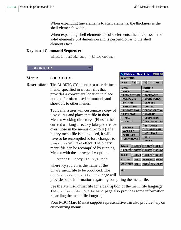
Mentat Help Commands in S MSC.Mentat Help ReferenceS-954
When expanding line elements to shell elements, the thickness is the shell element’s width.
When expanding shell elements to solid elements, the thickness is the solid element’s 3rd dimension and is perpendicular to the shell elements face.
Keyboard Command Sequence: shell_thickness <thickness>
SHORTCUTS
Menu: SHORTCUTS
Description: The SHORTCUTS menu is a user-defined menu, specified in user.ms, that provides a convenient location to place buttons for often-used commands and shortcuts to other menus.
Typically, a user will customize a copy of user.ms and place that file in their Mentat working directory. (Files in the current working directory take preference over those in the menus directory.) If a binary menu file is being used, it will have to be recompiled before changes to user.ms will take effect. The binary menu file can be recompiled by running Mentat with the -compile option:
mentat -compile xyz.msb
where xyz.msb is the name of the binary menu file to be produced. The doc/menu/MenuCompile.html page will provide some information regarding compiling the menu file.
See the Menus/Format file for a description of the menu file language. The doc/menu/MenuGuide.html page also provides some information regarding the menu file language.
Your MSC.Marc Mentat support representative can also provide help on customizing menus.
SHORTCUTS

S-955MSC.Mentat Help Reference Mentat Help Commands in S
ALL
Command: show_all_views
Description: This command specifies that all four views are to be displayed. To show only one model view, use the show_view command.
This command also activates all four views, making them respond to most view setting commands.
Also see: show_view and activate_all_views.
Keyboard Command Sequence: show_all_views
Another Button with the same description:SHOW ALL VIEWS
SHOW
Command: show_annotation
Description: This command displays information about annotations. Annotations are specified by number.
Keyboard Command Sequence: show_annotation <annotation number>
COMPOSITE
Command: show_composite
Description: This command specifies that the current composite material is to be displayed. Material layers and their relative thicknesses can be seen.
Keyboard Command Sequence: show_composite
Another Button with the same description:SHOW COMPOSITE
ALL
SHOW
COMPOSITE
Mentat Help Commands in S MSC.Mentat Help ReferenceS-956
SHOW
Command: show_curves
Description: This command displays information about the specified curve.
Keyboard Command Sequence: show_curves <curve id>
SHOW
Command: show_elements
Description: This command displays information about the specified element.
Keyboard Command Sequence: show_elements <element id>
HISTORY PLOT
Command: show_history
Description: This command specifies that the history plot is to be displayed. To display the model, use the show_model command.
Keyboard Command Sequence: show_history
Another Button with the same description:SHOW HISTORY
SHOW
SHOW
HISTORY PLOT

S-957MSC.Mentat Help Reference Mentat Help Commands in S
MODEL
Command: show_model
Description: This command specifies that the model is to be displayed. This command is particularly useful after viewing table, history, or path plots.
Keyboard Command Sequence: show_model
Another Button with the same description:SHOW MODEL
NODE INFO
Command: show_nodes
Description: This command displays information about the specified node.
Keyboard Command Sequence:
show_nodes <node id>
Another Button with the same description:
SHOW
DESIGN PLOT
Command: show_opt_plot
Description: This command specifies that the response gradient plot is to be displayed. To display the model, use the show_model command.
Keyboard Command Sequence:
show_opt_plot
Another Button with the same description:
SHOW DSGN PLOT
MODEL
NODE INFO
DESIGN PLOT
Mentat Help Commands in S MSC.Mentat Help ReferenceS-958
PATH PLOT
Command: show_pathplot
Description: This command specifies that the path plot is to be displayed. To display the model, use the show_model command.
Keyboard Command Sequence:
show_pathplot
Another Button with the same description:
SHOW PATH PLOT
POINT INFO
Command: show_points
Description: This command displays information about the specified point.
Keyboard Command Sequence:
show_points <point id>
Another Button with the same description:
SHOW
BEAM SECTION
Command: show_section
Description: This command specifies that the current beam section is to be displayed. The branches and their thicknesses are displayed in 2-D space.
Keyboard Command Sequence:
show_section
Another Button with the same description:
SHOW BEAM SECT
PATH PLOT
POINT INFO
BEAM SECTION
S-959MSC.Mentat Help Reference Mentat Help Commands in S
SHOW
Command: show_solids
Description: This command displays information about the specified solid.
Keyboard Command Sequence:
show_solids <solid id>
SHOW
Command: show_surfaces
Description: This command displays information about the specified surface.
Keyboard Command Sequence:
show_surfaces <surface id>
SHOW TABLE
Command: show_table
Description: This command specifies that the table is to be displayed. To display the model, use the show_model command.
Keyboard Command Sequence:
show_table
Another Button with the same description:
TABLE
SHOW
SHOW
SHOW TABLE
Mentat Help Commands in S MSC.Mentat Help ReferenceS-960
1
Command: show_view
Description: This command specifies the graphics area view that is to be displayed. You must specify the number of the view to show. To show all views, use the show_all_views command.
This command also activates the specified view, making it respond to most view setting commands. The previously shown view is deactivated.
Also see: show_all_views and activate_view.
Keyboard Command Sequence:
show_view <1, 2, 3, or 4>
Other Buttons with the same description:
2, 3, and 4
DATA FIT
Command: show_xcurve
Description: Toggle the display from showing the model to the curves supplied by the experimental data capability.
Keyboard Command Sequence:
show_xcurve
Another Button with the same description:
SHOW DATA FIT
1
DATA FIT

S-961MSC.Mentat Help Reference Mentat Help Commands in S
SIGNIORINI
Command: xcv_model signiorini
Description: This command is used if experimental data must be fitted using the Signiorini strain energy function W, which is given by:
W = C10*(I1 - 3) + C01*(I2 - 3) + C20*(I1 - 3)^2
where I1 and I2 are the first and second invariant of the right Cauchy-Green strain tensor and C10, C01, and C20 are the material parameters to be determined.
For this model, a volumetric test cannot be supplied. The user may enter a bulk modulus (material_type mechanical:mooney). If no bulk modulus is given, Marc assumes (nearly) incompressible material behavior.
Keyboard Command Sequence:
xcv_model signiorini
SINCER
Subroutine: SINCER
Description: The user subroutine SINCER allows you to define how much an elastic stress increment exceeds the yield stress. This allows the program to accurately take large increments such that the material goes from elastic to elastic-plastic. You return the value of FPLAS, which is the fraction of the stress increment beyond the yield surface. SINCER should only be used if a yield surface other than the von Mises (J2) is used in conjunction with the Generalized Plasticity option.
SIZE
Menu: SIZES
Description: This menu contains a display of the numbers of entities in the model and the amount of space they occupy in the database.
SIGNIORINI
SINCER
SIZE

Mentat Help Commands in S MSC.Mentat Help ReferenceS-962
MECHANICAL (AURICCHIO’S)
Menu: MATERIAL PROPERTIES->SHAPE MEMORY ALLOYS->MECHANICAL (AURICCHIO’S)
Description: The mechanical shape memory alloy model was implemented based on the works of Auricchio, “A robust integration-algorithm for a finite-strain shape memory–alloy superelastic model”, Int. J. Plasticity, Vol.17, pp. 971-990 (2001).
The input parameters are explained as follows:
sigAS_s: Initial Stress for Austenite to MartensitesigAS_f: Final Stress for Austenite to MartensitesigSA_s: Initial Stress for Martensite to AustenitesigSA_f: Initial Stress for Martensite to Austenite
Alpha:
Alpha is a pressure factor and it is measured from the difference between the response in tension and compression.
Case 1)If the behaviors in tension and compression are the same, the value is set to ZERO.
Case 2)If the behaviors in tension and compression have a difference as in the classical case of SMA, the value is set to 0.1 if there is no compression data for the phase transformation.
One value for the phase transformation in compression, let’s say sigAS_s_compression is available.
Then, alpha is calculated as follows:
alpha = sqrt(2/3) (sigAS_s_compression - sigAS_s) / (sigAS_s_compression + sigAS_s)
epsL:epsL is a scalar parameter representing the maximum deformation obtainable only by detwinning of the multiple-variant martensite (or Maximum strain obtainable by variant orientation).
Classical values for epsL are in the range 0.05 and 0.10.
MSC.Marc sets the default value as 0.07.
MECHANICAL (AURICCHIO’S)
S-963MSC.Mentat Help Reference Mentat Help Commands in S
THERMO-MECHANICAL MODEL
Menu: MATERIAL PROPERTIES->SHAPE MEMORY ALLOWS->THERMO-MECHANICAL MODEL
Description: The material properties for SMA is well described in the website:http://www.sma-inc.com/NiTiProperties.html. The input parameters used for thermo-mechanical shape memory alloy model and recommended values based on literature survey are explained as follows:
1. Young’s modulus, Poisson’s ratios, and thermal expansion coefficients for Austenite and Martensite: E_M, E_A, v_A, v_M, alpha_M, alpha_M.
• The recommended values:E_M = 28000-41000 MpaE_A = 60000-83000 Mpav_A = v_M = 0.33alpha_M: 6.6E-6 /deg Calpha_A: 11.0E-6 / deg C
2. Yield stresses of the pure martensite and austenite phases: sig_M and sig_A.
• The recommended values:sig_M = 70 -140 Mpasig_A = 195 -690 Mpa
Generally, in thermo-mechanical model, total strain is additive form with several strains like
E = E(el: elastic strain) + E(pl: plastic strain)+ E(ph: phase transformation strain)+ E(th: thermo-expansion strain).
If user does not want to consider plastic strain, put sig_M and sig_A with high value as follows:
sig_M = sig_A = 1.0e+20 Mpa
3. The “unstressed transformation temperatures”: Temp_Ms, Temp_Mf, Temp_As, Temp_Af. The Transformation Temperatures (TTRs) are those temperatures at which the alloy changes from the higher temperature Austenite to the lower temperature Martensite or vice versa. The typical tests to determining TTRs are Constant Load method, Differential Scanning Calorimeter (DSC) method, and Active Af method (please see the details in the
THERMO-MECHANICAL MODEL
Mentat Help Commands in S MSC.Mentat Help ReferenceS-964
website: http://www.sma-inc.com/NiTiProperties.html).
The range of transformation temperature is –200 to 100 deg C. So, it is difficult to recommend the default values. However, here is a guideline for two deferent SMA materials.
• The example values for SMA:SMA 1)Temp_Ms: -100 deg C, Temp_Mf: -50 deg C, Temp_As: 5 deg C, Temp_Af: 20 deg C
SMA 2) Temp_Ms: -145.15 deg C, Temp_Mf: -83.15 deg C, Temp_As: -85.15 deg C, Temp Af: -52.15 deg C
4. The coefficients Cm and Ca:
Provide the stress dependency of the transformation temperature as shown in theory manual.
• The recommended values:C_M = 6.0 Mpa / deg C, C_A = 8.0 Mpa / deg C
5. The calibration of the transformation strains: deviatoric transformation strain, volumetric transformation strain and detwinning stress.
• The recommended values:Deviatoric transformation strain: 0.08Volumetric transformation strain: 0 – 0.003.Detwinning stress: 100-150 Mpa
6. The calibration of the detwinning function:
“g” function is to fit the uniaxial stress vs. strain curve for pure, randomly oriented martensite conducted at a temperature below the Mf temperature.
• The recommended values for g-function:g-a = -4.0g-b = 2.0g-c <=0g-d = 2.75g-e <=0g-f = 3.0g-0 = 1.0e+20
(Cut off values)g-max: 1.0stress at g-max: 1.0e+20
S-965MSC.Mentat Help Reference Mentat Help Commands in S
SOLID AREA
Command: solid_area
Description: This command calculates the total surface area of a set of solids. The specified set of solids do not have to be connected; the area is calculated as the sum of the areas of the individual solids.
Keyboard Command Sequence:
solid_area <solid list> #
solid_edge_divisions
Command: solid_edge_divisions
Description: This command specifies the number of element edges desired when automatically meshing a solid. For triangular and tetrahedral meshes, this will be matched exactly. Quadrilateral meshes will only match when the number of divisions is even. If an odd number of edges is specified, then the number of element edges created will be greater than one specified.
Keyboard Command Sequence:
solid_edge_divisions <ndiv> <solid edge list>
solid_edge_length
Command: solid_edge_length
Description: This command specifies the number of element edges desired when automatically meshing a solid. The number of divisions is determined by dividing the length of the edge by the length specified in the command, and rounding up to the next integer.
Keyboard Command Sequence:
solid_edge_length <length> <solid edge list>
SOLID AREA
solid_edge_divisions
solid_edge_length
Mentat Help Commands in S MSC.Mentat Help ReferenceS-966
ELEMENTS
Command: solid_elements
Description: This command causes the specified elements to be drawn in solid color. Elements can be drawn in translucent color with the translucent_elements command.
Keyboard Command Sequence:
solid_elements <element list> #
solid_max_edge_divisions
Command: solid_max_edge_divisions
Description: This command assures that the number of edges divisions on every given solid edge is no greater than the given number.
Keyboard Command Sequence:
solid_max_edge_divisions <Number of Divisions><Solid Edge List>
solid_min_edge_divisions
Command: solid_min_edge_divisions
Description: This command assures that the number of edges divisions on every given solid edge is no less than the given number.
Keyboard Command Sequence:
solid_min_edge_divisions <Number of Divisions><Solid Edge List>
ELEMENTS
solid_max_edge_divisions
solid_min_edge_divisions

S-967MSC.Mentat Help Reference Mentat Help Commands in S
solid_quadmesh_faces
Command: solid_quadmesh_faces
Description: This command automatically creates quadrilateral meshes on the faces of solids. Mesh density is controlled by specifying the number of edge divisions desired on each edge.
Keyboard Command Sequence:
solid_quadmesh_faces <solid face list>
SOLIDS
Command: solid_solids
Description: This command causes the specified solids to be drawn in opaque color. Solids can be drawn in translucent color with the translucent_solids command.
Keyboard Command Sequence:
solid_solids <solids list> #
SOLIDS FACES
Command: solid_solids_faces
Description: This command causes the specified solids’ faces to be drawn in opaque color. Solids’ faces can be drawn in translucent color with the translucent_solids_faces command.
Keyboard Command Sequence:
solid_solids_faces <solids faces list> #
solid_quadmesh_faces
SOLIDS
SOLIDS FACES
Mentat Help Commands in S MSC.Mentat Help ReferenceS-968
SURFACES
Command: solid_surfaces
Description: This command causes the specified surfaces to be drawn in solid color. Surfaces can be drawn in translucent color with the translucent_surfaces command.
Keyboard Command Sequence:
solid_surfaces <surface list> #
solid_tetmesh_solids
Command: solid_tetmesh_solids
Description: This command automatically creates a tetrahedral mesh on solid bodies. Mesh density is controlled by specifying the number of edge divisions desired on each edge. The desired aspect ratio may also be specified.
Keyboard Command Sequence:
solid_tetmesh_solids <solid list>
solid_trimesh_faces
Command: solid_trimesh_faces
Description: This command automatically create triangular meshes on the faces of solids. Mesh density is controlled by specifying the number of edge divisions desired on each edge. The desired aspect ratio may also be specified.
Keyboard Command Sequence:
solid_trimesh_faces <solid face list>
SURFACES
solid_tetmesh_solids
solid_trimesh_faces
S-969MSC.Mentat Help Reference Mentat Help Commands in S
SOLID TYPE
Menu: SOLID TYPE
Description: This menu contains commands for setting the type of solids to be created.
SOLID VOLUME
Command: solid_volume
Description: This command calculates the total volume of a set of solids. The specified set of solids do not have to be connected; the volume is calculated as the sum of the volumes of the individual solids.
Keyboard Command Sequence:
solid_volume <solid list> #
SOLIDS
Menu: SOLIDS
Description: This menu contains commands that perform operations on solids.
SOLID
Command: solids_filledsolids_wireframe
Description: This button allows toggling between solid and wireframe display of solid.
If the toggle is ON, solid faces will be displayed with solid color.
If the toggle is OFF, will be displayed in wireframe mode.
Keyboard Command Sequence:
solids_filledsolids_wireframe
SOLID TYPE
SOLID VOLUME
SOLIDS
SOLID

Mentat Help Commands in S MSC.Mentat Help ReferenceS-970
SURFACES FLAT
Command: solids_flat
Description: This command causes solids faces to be drawn without Gouraud shading (color interpolation to give a smooth appearance).
Keyboard Command Sequence:solids_flat <on or off>
SHEAR RELAXATION
Command: xcv_model relax_spectrum
Description: This command is used if experimental shear relaxation data must be fitted using the following Prony series expansion for the shear modulus G:
NG(t) = G_infinity + sum{G_n*exp(-t/tau_n)} n=1
where t is the time, N is the number of terms and G_infinity, G_n and tau_n are material parameters to be determined.
The data points provided by the user must give the value of the shear modulus at different time stations, which do not need to be equi-spaced.
Keyboard Command Sequence: xcv_model relax_spectrum
BULK RELAXATION
Command: xcv_model relax_spectrum_bulk
Description: This command is used if experimental bulk relaxation data must be fitted using the following Prony series expansion for the bulk modulus K:
NK(t) = K_infinity + sum{K_n*exp(-t/tau_n)} n=1
where t is the time, N is the number of terms and K_infinity, K_n, and tau_n are material parameters to be determined.
SURFACES FLAT
SHEAR RELAXATION
BULK RELAXATION

S-971MSC.Mentat Help Reference Mentat Help Commands in S
The data points provided by the user must give the value of the bulk modulus at different time stations, which do not need to be equi-spaced.
Keyboard Command Sequence: xcv_model relax_spectrum_bulk
ENERGY RELAXATION
Command: xcv_model relax_spectrum_w
Description: This command is used if experimental strain energy relaxation data must be fitted using the following Prony series expansion for the strain energy W:
NW(t) = W_infinity + sum{delta_n*W0*exp(-t/tau_n)} n=1
where t is the time, N is the number of terms, W0 is the instantaneous strain energy, and W_infinity, delta_n, and tau_n are material parameters to be determined.
The data points provided by the user must give the value of the strain energy at different time stations, which do not need to be equi-spaced.
Keyboard Command Sequence: xcv_model relax_spectrum_w
SPLIT CURVES
Command: split_curves
Description: This command splits curves into multiple curves at cusp points. This is useful to assure that vertices are located only at the endpoints, and should be done before using the break_curves command.
Keyboard Command Sequence:
split_curves <curve_list>
ENERGY RELAXATION
SPLIT CURVES
Mentat Help Commands in S MSC.Mentat Help ReferenceS-972
SPLIT FACES
Command: split_solid_faces
Description: This command splits the periodic faces of solids such that they are no longer periodic. This is necessary for automatic meshing and should be used whenever periodic faces are present before meshing is performed.
Keyboard Command Sequence:
split_solid_faces <solid list>
DOF
Command: spring_dof
Description: This command sets the degrees of freedom at each end of the current spring class link. You must specify the slot (end) you wish to set and the degree of freedom. The slots are numbered 0 and 1. Degrees of freedom are specified as integers starting at 1.
Keyboard Command Sequence:
spring_dof <0 or 1> <dof>
NODE
Command: spring_node
Description: This command sets the nodes that make up the ends of the spring for the current spring class link. You must specify the slot (end) you wish to set and a node. The slots are numbered 0 and 1.
Keyboard Command Sequence:
spring_node <0 or 1> <node>
SPLIT FACES
DOF
NODE
S-973MSC.Mentat Help Reference Mentat Help Commands in S
STIFFNESS
Command: spring_optionspring_multi_option
Description: This command in the SPRINGS/DASHPOTS menu sets the property type for the current spring or for springs that will be created by subsequent calls to the link_multi_spring_n_to_1 and link_multi_spring_n_to_n commands.
Valid spring property types are as follows:
Keyboard Command Sequence:spring_option < >spring_multi_option < >
Other Buttons with the same description:DAMPING COEFFICIENT
Property Name Description
static_type:stiffness spring stiffness coefficient. Table used for nonlinear springs. Initial force optionally specified for linear springs. Numerical stabilizer can be turned on to zero out spring force.
static_type:force spring force – table as a function of displacement is mandatory.
dynamic_type:damping dashpot damping coefficient. Table used for nonlinear springs. Numerical stabilizer can be turned on to zero out dashpot force.
dynamic_type:force dashpot force – table as a function of velocity is mandatory.
thermal_type:heat spring heat transfer coefficient. Table used for nonlinear springs.
thermal_type:flux spring thermal flux. Table as a function of temperature is mandatory.
electrical_type:conductivity
spring electrical conductivity. Table used for nonlinear springs.
electrical_type:current spring current. Table as a function of voltage is mandatory.
STIFFNESS
Mentat Help Commands in S MSC.Mentat Help ReferenceS-974
SET
Command: spring_paramspring_multi_param
Description: This command in the SPRINGS/DASHPOTS menu sets the property values for the current spring or for springs that will be created by subsequent calls to the link_multi_spring_n_to_1 and link_multi_spring_n_to_n commands.
For a linear spring, these values are used directly. For a nonlinear spring (i.e. when a table is used in conjunction), these property values scale the values in the table.
Keyboard Command Sequence:
spring_param < >spring_multi_param < >
NUMERICAL STABILIZER
Command: spring_optionspring_multi_option
Description: If set to ON, the spring and damper force are always zeroed out and the spring only acts as a link. This is used for both linear and nonlinear springs. In the latter case, the stabilizer flag can only be set when the stiffness option is used for the spring.
Keyboard Command Sequence:
spring_option stabilizer:on | offspring_multi_option stabilizer:on | off
SET
NUMERICAL STABILIZER

S-975MSC.Mentat Help Reference Mentat Help Commands in S
TABLE
Command: spring_param_tablespring_multi_param_table
Description: This command in the SPRINGS/DASHPOTS menu sets the table for the current spring or for springs that are created by subsequent calls to the link_multi_spring_n_to_1 and link_multi_spring_n_to_n commands.
Valid spring table properties are as follows:
Property Name Description
stiffness spring stiffness table – table can be a function of time, normalized time, increment number, displacement, and/or temperature in a coupled analysis.
static_force spring force table – table as a function of displacement is mandatory. Other variables can be time, normalized time, increment number, and/or temperature in a coupled analysis.
damping dashpot damping table – table can be a function of time, normalized time, increment number, velocity and/or temperature in a coupled analysis.
dynamic_force dashpot force table – table as a function of velocity is mandatory. Other variables can be time, normalized time, increment number, and/or temperature in a coupled analysis.
heat spring heat transfer coefficient table – table can be a function of time, normalized time, increment number and/or temperature.
flux spring flux table – table as a function of temperature is mandatory. Other variables can be time, normalized time, increment number.
conductivity spring electrical conductivity table – table can be a function of time, normalized time, increment number, voltage and/or temperature in a coupled analysis.
TABLE

Mentat Help Commands in S MSC.Mentat Help ReferenceS-976
Keyboard Command Sequence:spring_param_table < >spring_multi_param_table < >
SSTRAN
Subroutine: SSTRAN
Description: The user subroutine SSTRAN allows the transformation of a substructure. The substructure may be either rotated, mirrored, or both.
SSTRAN is called every time you use a previously generated substructure.
STORE
Command: store_curves
Description: This command creates a set from a list of curves. You must specify the set name and a list of curves.
Keyboard Command Sequence:
store_curves <set name> <curve list> #
current spring current table – table as a function of voltage is mandatory. Other variables can be time, normalized time, increment number, and/or temperature in a coupled analysis.
Property Name Description
SSTRAN
STORE
S-977MSC.Mentat Help Reference Mentat Help Commands in S
STORE
Command: store_edges
Description: This command creates a set from a list of edges. You must specify the set name and a list of edges.
Keyboard Command Sequence:
store_edges <set name> <edge list> #
STORE
Command: store_elements
Description: This command creates a set from a list of elements. You must specify the set name and a list of elements.
Keyboard Command Sequence:
store_elements <set name> <element list> #
STORE
Command: store_faces
Description: This command creates a set from a list of faces. You must specify the set name and a list of faces.
Keyboard Command Sequence:
store_faces <set name> <face list> #
STORE
STORE
STORE
Mentat Help Commands in S MSC.Mentat Help ReferenceS-978
STORE NODE PATH
Command: store_node_path
Description: This command creates a set from a path of nodes. You must specify the set name and key nodes in a continuous path of nodes. The order of the nodes is maintained in the set.
Keyboard Command Sequence:
store_node_path <set name> <node path> #
STORE
Command: store_nodes
Description: This command creates a set from a list of nodes. You must specify the set name and a list of nodes.
Keyboard Command Sequence:
store_nodes <set name> <node list> #
STORE ORDERED
Command: store_nodes_ordered
Description: This command creates an ordered set of nodes. You must specify the set name and the nodes in the set. The order of the nodes is maintained in the set.
Keyboard Command Sequence:
store_nodes_ordered <set name> <nodes> #
STORE NODE PATH
STORE
STORE ORDERED
S-979MSC.Mentat Help Reference Mentat Help Commands in S
STORE
Command: store_points
Description: This command creates a set from a list of points. You must specify the set name and a list of points.
Keyboard Command Sequence:
store_points <set name> <point list> #
STORE
Command: store_surfaces
Description: This command creates a set from a list of surfaces. You must specify the set name and a list of surfaces.
Keyboard Command Sequence:
store_surfaces <set name> <surface list> #
STRESS PT ID’s
Command: stress_pt_labels
Description: This command toggles the drawing of stress points on beam sections.
Keyboard Command Sequence:
stress_pt_labels <on or off>
STRETCH
Menu: STRETCH
Description: This menu contains commands that relocate nodes along a straight line.
STORE
STORE
STRESS PT ID’s
STRETCH

Mentat Help Commands in S MSC.Mentat Help ReferenceS-980
BIAS FACTOR
Command: stretch_bias
Description: This command specifies the bias factor used by the stretch_nodes command. The bias factor is a number between -1 and 1 which affects the positioning of nodes. A positive bias factor causes the nodes to be stretched toward the first specified node. A negative bias factor causes the nodes to be stretched toward the last node specified. Biasing is parabolic. A bias factor of zero (the default) causes the nodes to be spaced equally along the path.
Singularities may occur if the magnitude of the bias factor is greater than one third.
Keyboard Command Sequence:
stretch_bias <bias factor>
NODES
Command: stretch_nodes
Description: This command repositions (stretches) nodes along a node path. The positioning of the nodes is affected by the current bias factor set by the stretch_bias command. You must specify a node path of at least three nodes. The first and last nodes in the path determine the endpoints of the line along which nodes are repositioned.
Keyboard Command Sequence:
stretch_nodes <first node> <additional nodes><last node> #
BIAS FACTOR
NODES

S-981MSC.Mentat Help Reference Mentat Help Commands in S
BIAS FACTORS
Command: sub_bias_factors
Description: This command sets the bias factors used by the subdivide command. Bias factors are specified for each of the element’s principle directions. (For line elements, only the U-direction factor is used. For two-dimensional elements, only the U- and V-direction factors are used.) Bias factors are numbers between -1 and 1.
Positive factors skew new element creation position in the element’s positive direction, negative factors skew it in the negative direction, and 0 bias factors produce evenly distributed elements.
Keyboard Command Sequence:
sub_bias_factors <U-direction factor><V-direction factor> <W-direction factor>
DIVISIONS
Command: sub_divisions
Description: This command sets the number of elements that are created from every element specified for the subdivide command.
Keyboard Command Sequence:
sub_divisions <number of elements in U><number of elements in V><number of elements in W>
SUBDIVIDE
Menu: SUBDIVIDE
Description: This menu contains commands that generate elements by subdividing existing one, two, or three-dimensional elements.
BIAS FACTORS
DIVISIONS
SUBDIVIDE
Mentat Help Commands in S MSC.Mentat Help ReferenceS-982
CURVES
Command: subdivide_curves
Description: This command breaks specified curves into smaller curves. The number of curves created is controlled by the number of subdivisions set by the sub_divisions command. The size and location of the created curves is controlled by the bias factors set by the sub_bias_factors command.
Keyboard Command Sequence: subdivide_curves <curve list> #
ELEMENTS
Command: subdivide_elements
Description: This command breaks specified elements into smaller elements. The number of elements created is controlled by the number of subdivisions set by the sub_divisions command. The size and location of the created elements is controlled by the bias factors set by the sub_bias_factors command.
Keyboard Command Sequence: subdivide_elements <element list> #
ELEMENTS TO HEX
Command: subdivide_elements2hex
Description: This command converts TETRA4 and PENTA6 elements into HEX8 elements. Each TETRA4 element is converted into four HEX8 elements, and each PENTA6 element is converted into six HEX8 element.
In order to keep the mesh conformity, each existing HEX8 element is also broken into eight smaller HEX8 elements. The subdivision is not controlled by DIVISION NUMBERS and BIAS FACTORS.
Keyboard Command Sequence: subdivide_elements2hex <element list> #
CURVES
ELEMENTS
ELEMENTS TO HEX

S-983MSC.Mentat Help Reference Mentat Help Commands in S
ELEMENTS TO QUAD
Command: subdivide_elements2quad
Description: This command converts TRIA3 elements into QUAD4 elements by adding one node interior to each triangle and three nodes on the three edges. Therefore, each triangular element is converted into three quad elements.
In order to keep the mesh conformity, each existing QUAD4 element is also broken into four smaller quad elements. The subdivision is not controlled by DIVISION NUMBERS and BIAS FACTORS.
Keyboard Command Sequence:
subdivide_elements2quad <element list> #
RESET
Command: subdivide_reset
Description: This command resets the subdivide divisions and bias factors used by the subdivide command to their default value.
Keyboard Command Sequence:
subdivide_reset
ELEMENTS TO QUAD
RESET

Mentat Help Commands in S MSC.Mentat Help ReferenceS-984
SUBMIT 1
Command: submit_job
Description: This command submits a job to the MSC.Marc analysis program. It first writes an input deck with a name of the form model_job.dat and then starts the job. The job submission files submit1, submit2, and submit3, located in the tools directory, may be tailored by the user. You must specify the job submission number (1, 2, or 3) which specifies which job submission file to use.
If a submit_job is done after opening a database file (mfd file) and MSC.Marc Mentat responds with Job already running!, do a RESET (job_submit_reset) and then submit the job again.
Keyboard Command Sequence:
submit_job <1, 2, or 3>
Other Buttons with the same description:
SUBMIT 2SUBMIT 3
SURFACES TO INTERPOLATED
Command: surface_interpolated
Description: This command converts surfaces into interpolated surfaces. The original surface is sampled at the user defined subdivisions and an interpolated surface is passed through them. The resulting surface is a bicubic NURBS surface with C1 and C2 continuity.
Keyboard Command Sequence:
surface_interpolated <surface list> #
SUBMIT 1
SURFACES TO INTERPOLATED

S-985MSC.Mentat Help Reference Mentat Help Commands in S
SURFACES TO POLYQUADS
Command: surface_polyquads
Description: This command converts the specified surfaces into polyquads (surfaces composed of a regular array quadrilateral patches).
Keyboard Command Sequence: surface_polyquads <surface list> #
SURFACE TYPE
Menu: SURFACE TYPE
Description: This menu contains commands for setting the type of geometric surfaces to be created with the add_surfaces command.
Available surface types are as follows:
QUAD A bilinear surface defined by four corner points.
BEZIER A bezier surface defined by a list of control points.
DRIVEN A surface defined by a driven curve and a driving curve.
NURB A general NURBS surface given by a complete definition: the number of control points in each direction, the curve order in each direction, a list of control points, a list of homogeneous coordinates, and a knot vector.
RULED A linear surface between two curves.
SPHERE A sphere by giving the center and radius.
CYLINDER A cylindrical (or conical) surface.
SWEPT A surface defined by a swept curve, a sweeping curve, and the number of steps.
INTERPOLATE A cubic NURBS surface that interpolates npu*npv control points.
COONS Coons linear surface defined by four boundary curves.
SKIN Smooth curve passing through a list of curves.
SURFACES TO POLYQUADS
SURFACE TYPE
Mentat Help Commands in S MSC.Mentat Help ReferenceS-986
SURFACES FLAT
Command: surfaces_flat
Description: This command causes surface faces to be drawn without Gouraud shading (color interpolation to give a smooth appearance).
Keyboard Command Sequence:
surfaces_flat <on or off>
SOLID
Command: surfaces_solidsurfaces_wireframe
Description: This button allows toggling between solid and wireframe display of surfaces. If the toggle is ON, surfaces will be displayed with solid color. If the toggle is OFF, surfaces will be displayed in wireframe mode. In this mode, surface faces will be represented by a diagonal line indicating the first edge.
Keyboard Command Sequence:
surfaces_solidsurfaces_wireframe
Another Button with the same description:
SURF’S
SAMPLED A surface created by a sequence of points. It is useful for creating surfaces from digitized data. Input is the origin point of the surface, a point in the first direction (to establish the first direction of the surface), then a point in the second direction of the surface (to establish the second direction of the surface), and then all the points that will define the surface (including selecting the origin point and the points in the first and second directions again).
SURFACES FLAT
SOLID

S-987MSC.Mentat Help Reference Mentat Help Commands in S
SWEEP
Menu: SWEEP
Description: This menu contains commands for cleaning up the model. There are commands for removing coincident entities, renumbering entities, and removing unused entities. Entities affected by these commands include points, curves, surfaces, nodes, and elements.
ALL
Command: sweep_all
Description: This command removes coincident points, curves, surfaces, nodes, and elements from the mesh. These entities are considered to be coincident if they occupy the same space within the tolerance distance specified with the set_sweep_tolerance command. This command removes coincident entities throughout the model; i.e. no list of entities is required.
Keyboard Command Sequence:
sweep_all
CURVES
Command: sweep_curves
Description: This command removes coincident curves from the specified list. Curves are coincident if they have identical points, weights, and knots. It is generally recommended to remove coincident points with the sweep_points command before executing this command. All but one of each set of coincident curves are removed.
Keyboard Command Sequence:
sweep_curves <curve list> #
SWEEP
ALL
CURVES
Mentat Help Commands in S MSC.Mentat Help ReferenceS-988
ELEMENTS
Command: sweep_elements
Description: This command removes coincident elements from the specified list. Elements are coincident if they have identical nodes and are of the same class. It is generally recommended to remove coincident nodes with the sweep_nodes command before executing this command. All but one of each set of coincident elements are removed.
Keyboard Command Sequence:
sweep_elements <element list> #
NODES
Command: sweep_nodes
Description: This command removes coincident nodes from the specified list. Nodes are considered to be coincident if they are located closer than the tolerance distance specified with the set_sweep_tolerance command. All but one of each set of coincident nodes are removed.
Keyboard Command Sequence:
sweep_nodes <node list> #
Another Button with the same description:
SWEEP OUTLINE NODES
POINTS
Command: sweep_points
Description: This command removes coincident points from the specified list. Points are considered to be coincident if they are located closer than the tolerance distance specified with the set_sweep_tolerance command. All but one of each set of coincident points are removed.
Keyboard Command Sequence:
sweep_points <point list> #
ELEMENTS
NODES
POINTS
S-989MSC.Mentat Help Reference Mentat Help Commands in S
SURFACES
Command: sweep_surfaces
Description: This command removes coincident surfaces from the specified list. Surfaces are coincident if they have identical points, weights, and knots. It is generally recommended to remove coincident points with the sweep_points command before executing this command.
Keyboard Command Sequence:
sweep_surfaces <surface list> #
SYMMETRY
Menu: SYMMETRY
Description: This menu contains the command for duplicating entities about a plane in space using symmetry.
SYMMETRY
Command: symmetry_combinedset_symmetry_combined
Description: The symmetry_combined command duplicates, by reflection with respect to a plane a mixed list of items simultaneously. The list may contain items of the following types:
Any attach relations that exist between the original mesh and geometry are duplicated for the copies of the mesh and the geometry.
The kind of items that are accepted by the command are controlled by the set_symmetry_combined command. This command activates or deactivates item types for a subsequent combined symmetry operation. Only active types are accepted by the symmetry_combined command and only items of these types are graphically pickable using the usual single
nodes elements points curvessurfaces solids springs servosties rbe2s rbe3s cavities
SURFACES
SYMMETRY
SYMMETRY

Mentat Help Commands in S MSC.Mentat Help ReferenceS-990
pick, box pick, and polygon pick methods if the symmetry_combined command is executed. This allows, for example, to simultaneously duplicate elements and surfaces, but not curves. Wildcards like all_existing and all_selected can also be used with this command to indicate all existing or all selected items of the active types.
The plane of symmetry is defined by a point and a normal vector, set by the set_symmetry_point and set_symmetry_normal commands, respectively.
Also see: symmetry_nodessymmetry_elementssymmetry_pointssymmetry_curvessymmetry_surfacessymmetry_solidssymmetry_tiessymmetry_servossymmetry_springssymmetry_rbe2ssymmetry_rbe3s
This button is located in the MESH GENERATION->SYMMETRY menu.
Keyboard Command Sequence: symmetry_combined <item list> #set_symmetry_combined <item type> <on|off>
CURVES
Command: symmetry_curves
Description: This command duplicates the specified curves about the plane defined by the point set by the set_symmetry_point command and a normal set by the set_symmetry_normal command. The control points associated with the curve are also duplicated.
Keyboard Command Sequence:
symmetry_curves <curve list> #
CURVES
S-991MSC.Mentat Help Reference Mentat Help Commands in S
ELEMENTS
Command: symmetry_elements
Description: This command duplicates the specified elements about the plane defined by the point set by the set_symmetry_point command and a normal set by the set_symmetry_normal command.
Keyboard Command Sequence:
symmetry_elements <element list> #
NODES
Command: symmetry_nodes
Description: This command duplicates the specified nodes about the plane defined by the point set by the set_symmetry_point command and a normal set by the set_symmetry_normal command.
Keyboard Command Sequence:
symmetry_nodes <node list> #
POINTS
Command: symmetry_points
Description: This command duplicates the specified points about the plane defined by the point set by the set_symmetry_point command and a normal set by the set_symmetry_normal command.
Keyboard Command Sequence:
symmetry_points <point list> #
ELEMENTS
NODES
POINTS

Mentat Help Commands in S MSC.Mentat Help ReferenceS-992
RBE2S
Command: symmetry_rbe2s
Description: This command duplicates the specified RBE2’s about the plane defined by the point set by the set_symmetry_point command and a normal set by the set_symmetry_normal command.
This button is located in the MESH GENERATION->SYMMETRY menu.
Keyboard Command Sequence: symmetry_rbe2s <rbe2 list> #
RBE3S
Command: symmetry_rbe3s
Description: This command duplicates the specified RBE3’s about the plane defined by the point set by the set_symmetry_point command and a normal set by the set_symmetry_normal command.
This button is located in the MESH GENERATION->SYMMETRY menu.
Keyboard Command Sequence: symmetry_rbe3s <rbe3 list> #
RESET
Command: symmetry_reset
Description: This command resets the symmetry plane point and normal used by the symmetry commands to their default values.
Keyboard Command Sequence:
symmetry_reset
RBE2S
RBE3S
RESET

S-993MSC.Mentat Help Reference Mentat Help Commands in S
NODES
Command: symmetry_servos
Description: This command duplicates the specified servo links about the plane defined by the point set by the set_symmetry_point command and a normal set by the set_symmetry_normal command.
This button is located in the MESH GENERATION->SYMMETRY menu.
Keyboard Command Sequence: symmetry_servos <servo link list> #
SOLIDS
Command: symmetry_solids
Description: This command duplicates the specified solids about the plane defined by the point set by the set_symmetry_point command and a normal set by the set_symmetry_normal command.
Keyboard Command Sequence:
symmetry_solids <solid list> #
NODES
Command: symmetry_springs
Description: This command duplicates the specified springs about the plane defined by the point set by the set_symmetry_point command and a normal set by the set_symmetry_normal command.
This button is located in the MESH GENERATION->SYMMETRY menu.
Keyboard Command Sequence: symmetry_springs <spring list> #
SERVOS
SOLIDS
SPRINGS
Mentat Help Commands in S MSC.Mentat Help ReferenceS-994
SURFACES
Command: symmetry_surfaces
Description: This command duplicates the specified surfaces about the plane defined by the point set by the set_symmetry_point command and a normal set by the set_symmetry_normal command.
Keyboard Command Sequence:
symmetry_surfaces <surface list> #
TIES
Command: symmetry_ties
Description: This command duplicates the specified nodal ties about the plane defined by the point set by the set_symmetry_point command and a normal set by the set_symmetry_normal command.
This button is located in the MESH GENERATION->SYMMETRY menu.
Keyboard Command Sequence: symmetry_ties <tie list> #
ALIGN
Command: system_align
Description: This command defines a user coordinate system using the three specified points. You must specify the origin, a point on the U-axis, and a point on the V-axis. All three points are specified in global coordinates.
Keyboard Command Sequence:
system_align <XYZ coordinates of origin><XYZ coordinates of U-axis point><XYZ coordinates of V-axis point>
SURFACES
TIES
ALIGN
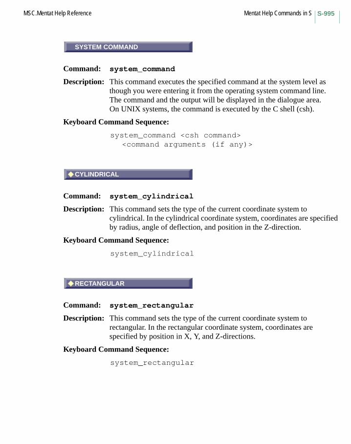
S-995MSC.Mentat Help Reference Mentat Help Commands in S
SYSTEM COMMAND
Command: system_command
Description: This command executes the specified command at the system level as though you were entering it from the operating system command line. The command and the output will be displayed in the dialogue area. On UNIX systems, the command is executed by the C shell (csh).
Keyboard Command Sequence:
system_command <csh command><command arguments (if any)>
CYLINDRICAL
Command: system_cylindrical
Description: This command sets the type of the current coordinate system to cylindrical. In the cylindrical coordinate system, coordinates are specified by radius, angle of deflection, and position in the Z-direction.
Keyboard Command Sequence:
system_cylindrical
RECTANGULAR
Command: system_rectangular
Description: This command sets the type of the current coordinate system to rectangular. In the rectangular coordinate system, coordinates are specified by position in X, Y, and Z-directions.
Keyboard Command Sequence:
system_rectangular
SYSTEM COMMAND
CYLINDRICAL
RECTANGULAR

Mentat Help Commands in S MSC.Mentat Help ReferenceS-996
RESET
Command: system_reset
Description: This command resets the coordinate system to the default global rectangular coordinate system.
Keyboard Command Sequence:
system_reset
ROTATE
Command: system_rotate
Description: This command rotates the coordinate system about the global X, Y, and Z-axes in that order. You must specify the rotations in degrees.
Keyboard Command Sequence:
system_rotate <X-axis rotation> <Y-axis rotation><Z-axis rotation>
SYSTEM SHELL
Command: system_shell
Description: This command invokes an operating system shell from within MSC.Marc Mentat. This allows you to execute system commands without leaving MSC.Marc Mentat. To return from the shell after you have finished with the shell, type a carriage return. On UNIX systems, you must specify the type of shell you want, C shell (csh) or Bourne shell (sh).
Keyboard Command Sequence: system_shell <csh or sh>
RESET
ROTATE
SYSTEM SHELL
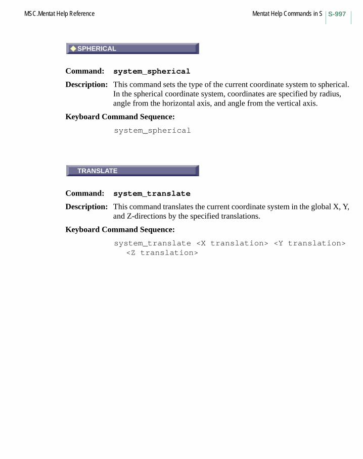
S-997MSC.Mentat Help Reference Mentat Help Commands in S
SPHERICAL
Command: system_spherical
Description: This command sets the type of the current coordinate system to spherical. In the spherical coordinate system, coordinates are specified by radius, angle from the horizontal axis, and angle from the vertical axis.
Keyboard Command Sequence:
system_spherical
TRANSLATE
Command: system_translate
Description: This command translates the current coordinate system in the global X, Y, and Z-directions by the specified translations.
Keyboard Command Sequence:
system_translate <X translation> <Y translation><Z translation>
SPHERICAL
TRANSLATE

Mentat Help Commands in S MSC.Mentat Help ReferenceS-998

Mentat Help Commands in TTABLE
Menu: TABLE
Description: This menu contains commands for defining tables. Tables represent functions that can be used to define the variation of a quantity versus other parameters such as variables can be time, increment, temperature, density, plastic strain, stress, strain rate, and stress rate.
ADD POINT
Command: table_add
Description: This command adds a data point to the current table. The command adds another data point to the function y = f(x). You must specify the tabular x and y coordinates of the point to add.
Keyboard Command Sequence:
table_add <x value> <y value>
T Commands Begin with T
TABLE
ADD POINT

Mentat Help Commands in T MSC.Mentat Help ReferenceT-1000
CLEAR
Command: table_clear
Description: This command clears the current table. All data points are removed from the table.
Keyboard Command Sequence:
table_clear
DIFFERENTIATE
Command: table_differentiate
Description: This command numerically differentiates the function represented by the values in the current table and makes the new values in the table.
Also see the table_integrate command.
Use this command cautiously, as differentiation of tabular values is numerically unstable. (For example, if you differentiate a table twice and integrate twice, you may not end up with the same values that you started with.)
Keyboard Command Sequence:
table_differentiate
EDIT
Command: table_edit
Description: This command edits an existing tabular point. You must specify the point to be edited by number, and new tabular x and y coordinates of the point.
Keyboard Command Sequence:
table_edit <point number> <x value> <y value>
CLEAR
DIFFERENTIATE
EDIT

T-1001MSC.Mentat Help Reference Mentat Help Commands in T
FILL
Command: table_fill
Description: This command shifts and scales all table point values in the x and y-directions, so that the values fill the x and y limits of the current table.
Also see: table_fit, table_shift, and table_scale.
Keyboard Command Sequence:
table_fill
FILLED
Command: table_filledtable_unfilled
Description: These commands specify whether or not areas under tabular functions be filled with color.
Keyboard Command Sequence:
table_filledtable_unfilled
FIT
Command: table_fit
Description: This command adjusts the limits of the current table so that all table point values fit within those limits.
Also see: table_fill, set_table_xmin, set_table_xmax, set_table_ymin, and set_table_ymax.
Keyboard Command Sequence:
table_fit
FILL
FILLED
FIT

Mentat Help Commands in T MSC.Mentat Help ReferenceT-1002
ENTER
Command: table_formula
Description: This command specifies a formula to be used as the function represented by the table. You must specify an arithmetic expression in terms of the variable x.
Formulas should be entered as Fortran-like expressions. The expression can include transcendentals (SIN, COS, TAN, ASIN, ACOS, and ATAN). The LOG keyword returns a natural logarithm. The parameters PI and E are also available. Addition, multiplication, subtraction, and division are represented as +, *, -, /, respectively. The power of a number is represented by the symbol ^. You can use nesting to a level of 20 by enclosing expressions in parentheses.
Examples of legal expressions follow:
1.2e+05 * (3 * (sin(x) / 12.34)) / 2.0x^PI1.23 ^ (PI * sin(3 * 1.0e-02))
Keyboard Command Sequence:
table_formula <formula expression>
INTEGRATE
Command: table_integrate
Description: This command numerically integrates the function represented by the values in the current table and makes the new values in the table.
Also see the table_differentiate command.
Keyboard Command Sequence:
table_integrate
ENTER
INTEGRATE

T-1003MSC.Mentat Help Reference Mentat Help Commands in T
NAME
Command: table_name
Description: This command sets or changes the name of the current table.
Keyboard Command Sequence:
table_name <name>
READ
Command: table_read
Description: This command reads the specified file containing tabular data into a table. Note that this command creates a new entry in the list of tables and makes it the current table. To read tabular data into the current table, use the table_read_curr command.
The file must contain data of the correct form in order to be read successfully.
The tabular data file can be created by hand or produced by the table_write command and is written in free format. Comments are allowed in the file by placing a # at the beginning of the line. The order of the data is significant; its format (i.e. position on the line, number of items on each line) is not.
An example of a tabular data file is given below.
# Titletable1# X-axis LabelX# Y-axis LabelY# Type 0# Steps in X and Y 10 10# X-min, X-max, Y-min, Ymax 0.0 1.0 0.0 1.0# Number of Data Points 11# Data Points: X, Y, Point ID
NAME
READ

Mentat Help Commands in T MSC.Mentat Help ReferenceT-1004
0.000000000000e+00 0.000000000000e+00 1 1.000000000000e-01 1.000000000000e-01 2 2.000000000000e-01 2.000000000000e-01 3 3.000000000000e-01 3.000000000000e-01 4 4.000000000000e-01 4.000000000000e-01 5 5.000000000000e-01 5.000000000000e-01 6 6.000000000000e-01 6.000000000000e-01 7 7.000000000000e-01 7.000000000000e-01 8 8.000000000000e-01 8.000000000000e-01 9 9.000000000000e-01 9.000000000000e-01 10 1.000000000000e+00 1.000000000000e+00 11
Keyboard Command Sequence:
table_read <file name>
REEVALUATE
Command: table_reeval
Description: This command reevaluates the current table’s formula (set with the table_formula command) and redisplays the table. This command is useful after changing table limits and step sizes.
Also see: set_table_xmin, set_table_xmax, set_table_ymin, set_table_ymax, set_table_xstep, and set_table_ystep.
Keyboard Command Sequence:
table_reeval
REMOVE
Command: table_remove
Description: This command removes a data point from the current table. You must specify the point to be removed by number.
Keyboard Command Sequence:
table_remove <point number>
REEVALUATE
REMOVE

T-1005MSC.Mentat Help Reference Mentat Help Commands in T
READ
Command: table_readtable_writetable_read_rawtable_write_raw
Description: These commands read and write tables to a given file. Normally, all information about the table is read or written. In raw mode only xy pairs of data are used, all other information being excluded. This mode is to support transfering data from other programs.
Keyboard Command Sequence:
table_read <filename>table_write <filename>table_read_raw <filename>table_write_raw <filename>
Another Button with the same description:
WRITE
SCALE
Command: table_scale
Description: This command scales all table point values in the x and y-directions by the specified factors.
Keyboard Command Sequence:
table_scale <x factor> <y factor>
READ
SCALE
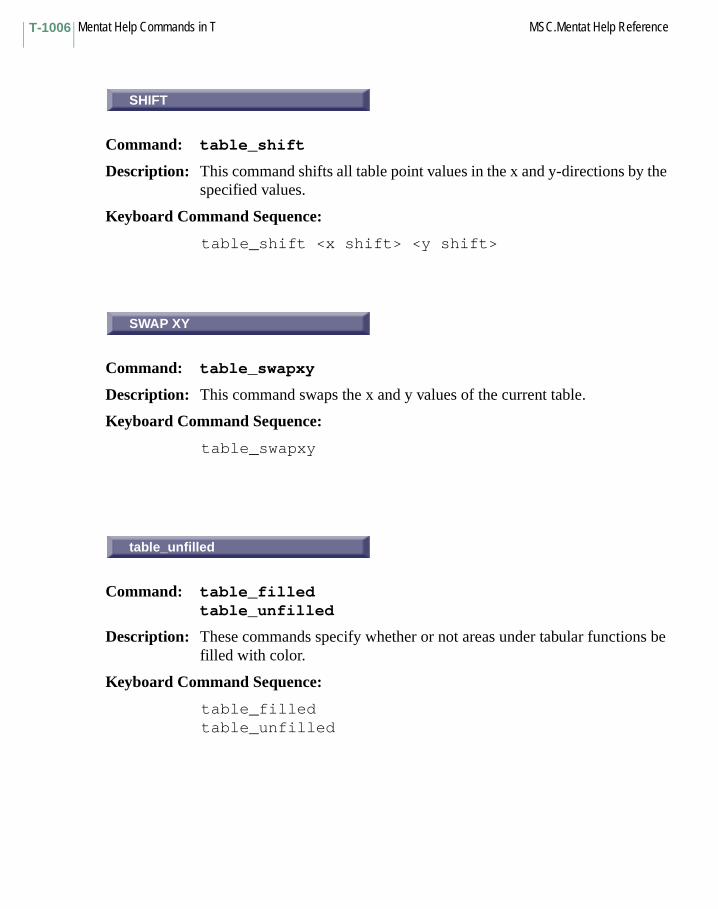
Mentat Help Commands in T MSC.Mentat Help ReferenceT-1006
SHIFT
Command: table_shift
Description: This command shifts all table point values in the x and y-directions by the specified values.
Keyboard Command Sequence:
table_shift <x shift> <y shift>
SWAP XY
Command: table_swapxy
Description: This command swaps the x and y values of the current table.
Keyboard Command Sequence:
table_swapxy
table_unfilled
Command: table_filledtable_unfilled
Description: These commands specify whether or not areas under tabular functions be filled with color.
Keyboard Command Sequence:
table_filledtable_unfilled
SHIFT
SWAP XY
table_unfilled

T-1007MSC.Mentat Help Reference Mentat Help Commands in T
table_write
Command: table_write
Description: This command writes a file that contains tabular data from the current table. Tabular data files can be read into the current table with the table_read command. You must specify the name of the file to write the data to.
Keyboard Command Sequence:
table_write <file name>
X FORMULA
Command: table_xformula
Description: This command specifies the formula that is used for displaying the x values of the current table. The x values are not modified; the formula only affects their plot positions.
Formulas should be entered as Fortran-like expressions. The expression can include transcendentals (SIN, COS, TAN, ASIN, ACOS, and ATAN). The LOG keyword returns a natural logarithm. The parameter PI is also available. Addition, multiplication, subtraction, and division are represented as +, *, -, /, respectively. The power of a number is represented by the symbol **. You can use nesting to a level of 20 by enclosing expressions in parentheses.
Examples of legal expressions follow:
1.2e+05 * (3 * (sin(x) / 12.34)) / 2.0x**PI1.23 ** (PI * sin(3 * 1.0e-02))
Keyboard Command Sequence:
table_xformula <formula expression>
table_write
X FORMULA
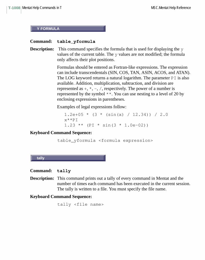
Mentat Help Commands in T MSC.Mentat Help ReferenceT-1008
Y FORMULA
Command: table_yformula
Description: This command specifies the formula that is used for displaying the y values of the current table. The y values are not modified; the formula only affects their plot positions.
Formulas should be entered as Fortran-like expressions. The expression can include transcendentals (SIN, COS, TAN, ASIN, ACOS, and ATAN). The LOG keyword returns a natural logarithm. The parameter PI is also available. Addition, multiplication, subtraction, and division are represented as +, *, -, /, respectively. The power of a number is represented by the symbol **. You can use nesting to a level of 20 by enclosing expressions in parentheses.
Examples of legal expressions follow:
1.2e+05 * (3 * (sin(x) / 12.34)) / 2.0x**PI1.23 ** (PI * sin(3 * 1.0e-02))
Keyboard Command Sequence:
table_yformula <formula expression>
tally
Command: tally
Description: This command prints out a tally of every command in Mentat and the number of times each command has been executed in the current session. The tally is written to a file. You must specify the file name.
Keyboard Command Sequence:
tally <file name>
Y FORMULA
tally
T-1009MSC.Mentat Help Reference Mentat Help Commands in T
TENSOF
Subroutine: TENSOF
Description: The user subroutine TENSOF allows the definition of the post-failure behavior at an integration point. By default, the reduction of the cracking stress to zero is a linear function of the crack strain.
TENSOF is automatically called for every crack in the analysis.
THIRD ORDER DEFORMATION
Command: xcv_model third_order_deformation
Description: This command is used if experimental data must be fitted using the third order deformation strain energy function W, which is given by:
W = C10*(I1 - 3) + C01*(I2 - 3)+ C11*(I1 - 3)*(I2 - 3) + C20*(I1 - 3)^2 + C30*(I1 - 3)^3
where I1 and I2 are the first and second invariant of the right Cauchy-Green strain tensor and C10, C01, C11, C20, and C30 are the material parameters to be determined.
For this model, a volumetric test cannot be supplied. The user may enter a bulk modulus (material_type mechanical:mooney).If no bulk modulus is given, Marc assumes (nearly) incompressible material behavior.
Keyboard Command Sequence:
xcv_model third_order_deformation
TENSOF
THIRD ORDER DEFORMATION
Mentat Help Commands in T MSC.Mentat Help ReferenceT-1010
TYPE
Command: tie_type
Description: This command sets the Marc tie type for the current nodal tie class link. Tie types are specified as integers. See MSC.Marc Volume C: Program Input Manual for valid tie types.
Keyboard Command Sequence:
tie_type <tie type>
DOF
Command: tied_dof
Description: This command sets the tied degree of freedom for the current servo link class link. Degrees of freedom are specified as integers starting at 1.
Keyboard Command Sequence:
tied_dof <tied dof>
NODE
Command: tied_node
Description: This command sets the tied node for the current nodal tie or servo link class link.
Keyboard Command Sequence:
tied_node <tied node>
TYPE
DOF
NODE

T-1011MSC.Mentat Help Reference Mentat Help Commands in T
BODIES
Command: touching_bodies
Description: Sets the current entry in the table to be modified. At least one of the bodies must be deformable.
The bodies are entered either by typing their names on the command line or by clicking on the entries in the pop-up menu.
Keyboard Command Sequence:
touching_bodies <first contact body><second contact body>
ALL+
Command: trans_camera_cspace_c_for
Description: This command translates the camera along the camera space X, Y, and Z-axes, each in the positive direction, and each by a distance set with the trans_camera_increment command.
This command acts on all the currently active views.
Also see: trans_camera_increment, activate_view, and the topic viewing for a general discussion of viewing.
Keyboard Command Sequence:
trans_camera_cspace_c_for
BODIES
ALL+

Mentat Help Commands in T MSC.Mentat Help ReferenceT-1012
ALL-
Command: trans_camera_cspace_c_rev
Description: This command translates the camera along the camera space X, Y, and Z-axes, each in the negative direction, and each by a distance set with the trans_camera_increment command.
This command acts on all the currently active views.
Also see: trans_camera_increment, activate_view, and the topic viewing for a general discussion of viewing.
Keyboard Command Sequence:
trans_camera_cspace_c_rev
X+
Command: trans_camera_cspace_x_for
Description: This command translates the camera along the camera space X-axis, in the positive direction, by a distance set with the trans_camera_increment command.
This command acts on all the currently active views.
Also see: trans_camera_increment, activate_view, and the topic viewing for a general discussion of viewing.
Keyboard Command Sequence:
trans_camera_cspace_x_for
ALL-
X+

T-1013MSC.Mentat Help Reference Mentat Help Commands in T
X-
Command: trans_camera_cspace_x_rev
Description: This command translates the camera along the camera space X-axis, in the negative direction, by a distance set with the trans_camera_increment command.
This command acts on all the currently active views.
Also see: trans_camera_increment, activate_view, and the topic viewing for a general discussion of viewing.
Keyboard Command Sequence:
trans_camera_cspace_x_rev
Y+
Command: trans_camera_cspace_y_for
Description: This command translates the camera along the camera space Y-axis, in the positive direction, by a distance set with the trans_camera_increment command.
This command acts on all the currently active views.
Also see: trans_camera_increment, activate_view, and the topic viewing for a general discussion of viewing.
Keyboard Command Sequence:
trans_camera_cspace_y_for
X-
Y+
Mentat Help Commands in T MSC.Mentat Help ReferenceT-1014
Y-
Command: trans_camera_cspace_y_rev
Description: This command translates the camera along the camera space Y-axis, in the negative direction, by a distance set with the trans_camera_increment command.
This command acts on all the currently active views.
Also see: trans_camera_increment, activate_view, and the topic viewing for a general discussion of viewing.
Keyboard Command Sequence:
trans_camera_cspace_y_rev
Z+
Command: trans_camera_cspace_z_for
Description: This command translates the camera along the camera space Z-axis, in the positive direction, by a distance set with the trans_camera_increment command.
This command acts on all the currently active views.
Also see: trans_camera_increment, activate_view, and the topic viewing for a general discussion of viewing.
Keyboard Command Sequence:
trans_camera_cspace_z_for
Y-
Z+

T-1015MSC.Mentat Help Reference Mentat Help Commands in T
Z-
Command: trans_camera_cspace_z_rev
Description: This command translates the camera along the camera space Z-axis, in the negative direction, by a distance set with the trans_camera_increment command.
This command acts on all the currently active views.
Also see: trans_camera_increment, activate_view, and the topic viewing for a general discussion of viewing.
Keyboard Command Sequence:
trans_camera_cspace_z_rev
TRANSLATE
Command: trans_camera_increment
Description: This command allows you to set the translation increment angle that will be used by subsequent camera translation commands such as trans_camera_cspace_x_for.
See the topic viewing for a general discussion of viewing.
Keyboard Command Sequence:
trans_camera_increment <delta>
Z-
TRANSLATE

Mentat Help Commands in T MSC.Mentat Help ReferenceT-1016
ALL+
Command: trans_camera_mspace_c_for
Description: This command translates the camera along the model space X, Y, and Z-axes, each in the positive direction, and each by a distance set with the trans_camera_increment command.
This command acts on all the currently active views.
Also see: trans_camera_increment, activate_view, and the topic viewing for a general discussion of viewing.
Keyboard Command Sequence:
trans_camera_mspace_c_for
ALL-
Command: trans_camera_mspace_c_rev
Description: This command translates the camera along the model space X, Y, and Z-axes, each in the negative direction, and each by a distance set with the trans_camera_increment command.
This command acts on all the currently active views.
Also see: trans_camera_increment, activate_view, and the topic viewing for a general discussion of viewing.
Keyboard Command Sequence:
trans_camera_mspace_c_rev
ALL+
ALL-
T-1017MSC.Mentat Help Reference Mentat Help Commands in T
X+
Command: trans_camera_mspace_x_for
Description: This command translates the camera along the model space X-axis, in the positive direction, by a distance set with the trans_camera_increment command.
This command acts on all the currently active views.
Also see: trans_camera_increment, activate_view, and the topic viewing for a general discussion of viewing.
Keyboard Command Sequence:
trans_camera_mspace_x_for
X-
Command: trans_camera_mspace_x_rev
Description: This command translates the camera along the model space X-axis, in the negative direction, by a distance set with the trans_camera_increment command.
This command acts on all the currently active views.
Also see: trans_camera_increment, activate_view, and the topic viewing for a general discussion of viewing.
Keyboard Command Sequence:
trans_camera_mspace_x_rev
X+
X-

Mentat Help Commands in T MSC.Mentat Help ReferenceT-1018
Y+
Command: trans_camera_mspace_y_for
Description: This command translates the camera along the model space Y-axis, in the positive direction, by a distance set with the trans_camera_increment command.
This command acts on all the currently active views.
Also see: trans_camera_increment, activate_view, and the topic viewing for a general discussion of viewing.
Keyboard Command Sequence:
trans_camera_mspace_y_for
Y-
Command: trans_camera_mspace_y_rev
Description: This command translates the camera along the model space Y-axis, in the negative direction, by a distance set with the trans_camera_increment command.
This command acts on all the currently active views.
Also see: trans_camera_increment, activate_view, and the topic viewing for a general discussion of viewing.
Keyboard Command Sequence:
trans_camera_mspace_y_rev
Y+
Y-

T-1019MSC.Mentat Help Reference Mentat Help Commands in T
Z+
Command: trans_model_mspace_z_for
Description: This command translates the model along the model space Z-axis, in the positive direction, by a distance set with the trans_model_increment command.
This command acts on all the currently active views.
Also see: trans_model_increment, activate_view, and the topic viewing for a general discussion of viewing.
Keyboard Command Sequence:
trans_model_mspace_z_for
Z-
Command: trans_camera_mspace_z_rev
Description: This command translates the camera along the model space Z-axis, in the negative direction, by a distance set with the trans_camera_increment command.
This command acts on all the currently active views.
Also see: trans_camera_increment, activate_view, and the topic viewing for a general discussion of viewing.
Keyboard Command Sequence:
trans_camera_mspace_z_rev
Z+
Z-
Mentat Help Commands in T MSC.Mentat Help ReferenceT-1020
ALL+
Command: trans_camera_vspace_c_for
Description: This command translates the camera along the view space X, Y, and Z-axes, each in the positive direction, and each by a distance set with the trans_camera_increment command.
This command acts on all the currently active views.
Also see: trans_camera_increment, activate_view, and the topic viewing for a general discussion of viewing.
Keyboard Command Sequence:
trans_camera_vspace_c_for
ALL-
Command: trans_camera_vspace_c_rev
Description: This command translates the camera along the view space X, Y, and Z-axes, each in the negative direction, and each by a distance set with the trans_camera_increment command.
This command acts on all the currently active views.
Also see: trans_camera_increment, activate_view, and the topic viewing for a general discussion of viewing.
Keyboard Command Sequence:
trans_camera_vspace_c_rev
ALL+
ALL-
T-1021MSC.Mentat Help Reference Mentat Help Commands in T
X+
Command: trans_camera_vspace_x_for
Description: This command translates the camera along the view space X-axis, in the positive direction, by a distance set with the trans_camera_increment command.
This command acts on all the currently active views.
Also see: trans_camera_increment, activate_view, and the topic viewing for a general discussion of viewing.
Keyboard Command Sequence:
trans_camera_vspace_x_for
X-
Command: trans_camera_vspace_x_rev
Description: This command translates the camera along the view space X-axis, in the negative direction, by a distance set with the trans_camera_increment command.
This command acts on all the currently active views.
See also: trans_camera_increment, activate_view, and the topic viewing for a general discussion of viewing.
Keyboard Command Sequence:
trans_camera_vspace_x_rev
X+
X-

Mentat Help Commands in T MSC.Mentat Help ReferenceT-1022
Y+
Command: trans_camera_vspace_y_for
Description: This command translates the camera along the view space Y-axis, in the positive direction, by a distance set with the trans_camera_increment command.
This command acts on all the currently active views.
Also see: trans_camera_increment, activate_view, and the topic viewing for a general discussion of viewing.
Keyboard Command Sequence:
trans_camera_vspace_y_for
Y-
Command: trans_camera_vspace_y_rev
Description: This command translates the camera along the view space Y-axis, in the negative direction, by a distance set with the trans_camera_increment command.
This command acts on all the currently active views.
Also see: trans_camera_increment, activate_view, and the topic viewing for a general discussion of viewing.
Keyboard Command Sequence:
trans_camera_vspace_y_rev
Y+
Y-

T-1023MSC.Mentat Help Reference Mentat Help Commands in T
Z+
Command: trans_camera_vspace_z_for
Description: This command translates the camera along the view space Z-axis, in the positive direction, by a distance set with the trans_camera_increment command.
This command acts on all the currently active views.
Also see: trans_camera_increment, activate_view, and the topic viewing for a general discussion of viewing.
Keyboard Command Sequence:
trans_camera_vspace_z_for
Z-
Command: trans_camera_vspace_z_rev
Description: This command translates the camera along the view space Z-axis, in the negative direction, by a distance set with the trans_camera_increment command.
This command acts on all the currently active views.
Also see: trans_camera_increment, activate_view, and the topic viewing for a general discussion of viewing.
Keyboard Command Sequence:
trans_camera_vspace_z_rev
Z+
Z-

Mentat Help Commands in T MSC.Mentat Help ReferenceT-1024
ALL+
Command: trans_model_cspace_c_for
Description: This command translates the model along the camera space X, Y, and Z-axes, each in the positive direction, and each by a distance set with the trans_model_increment command.
This command acts on all the currently active views.
Also see: trans_model_increment, activate_view, and the topic viewing for a general discussion of viewing.
Keyboard Command Sequence:
trans_model_cspace_c_for
ALL-
Command: trans_model_cspace_c_rev
Description: This command translates the model along the camera space X, Y, and Z-axes, each in the negative direction, and each by a distance set with the trans_model_increment command.
This command acts on all the currently active views.
Also see: trans_model_increment, activate_view, and the topic viewing for a general discussion of viewing.
Keyboard Command Sequence:
trans_model_cspace_c_rev
ALL+
ALL-
T-1025MSC.Mentat Help Reference Mentat Help Commands in T
TX+
Command: trans_model_cspace_x_for
Description: This command translates the model along the camera space X-axis, in the positive direction, by a distance set with the trans_model_increment command.
This command acts on all the currently active views.
Also see: trans_model_increment, activate_view, and the topic viewing for a general discussion of viewing.
Keyboard Command Sequence:
trans_model_cspace_x_for
Another Button with the same description:
X+
TX-
Command: trans_model_cspace_x_rev
Description: This command translates the model along the camera space X-axis, in the negative direction, by a distance set with the trans_model_increment command.
This command acts on all the currently active views.
See also trans_model_increment, activate_view, and the topic viewing for a general discussion of viewing.
Keyboard Command Sequence:
trans_model_cspace_x_rev
Another Button with the same description:
X-
TX+
TX-
Mentat Help Commands in T MSC.Mentat Help ReferenceT-1026
TY+
Command: trans_model_cspace_y_for
Description: This command translates the model along the camera space Y-axis, in the positive direction, by a distance set with the trans_model_increment command.
This command acts on all the currently active views.
Also see: trans_model_increment, activate_view, and the topic viewing for a general discussion of viewing.
Keyboard Command Sequence:
trans_model_cspace_y_for
Another Button with the same description:
Y+
TY-
Command: trans_model_cspace_y_rev
Description: This command translates the model along the camera space Y-axis, in the negative direction, by a distance set with the trans_model_increment command.
This command acts on all the currently active views.
See also trans_model_increment, activate_view, and the topic viewing for a general discussion of viewing.
Keyboard Command Sequence:
trans_model_cspace_y_rev
Another Button with the same description:
Y-
TY+
TY-
T-1027MSC.Mentat Help Reference Mentat Help Commands in T
TZ+
Command: trans_model_cspace_z_for
Description: This command translates the model along the camera space Z-axis, in the positive direction, by a distance set with the trans_model_increment command.
This command acts on all the currently active views.
Also see: trans_model_increment, activate_view, and the topic viewing for a general discussion of viewing.
Keyboard Command Sequence:
trans_model_cspace_z_for
Another Button with the same description:
Z+
TZ-
Command: trans_model_cspace_z_rev
Description: This command translates the model along the camera space Z-axis, in the negative direction, by a distance set with the trans_model_increment command.
This command acts on all the currently active views.
Also see: trans_model_increment, activate_view, and the topic viewing for a general discussion of viewing.
Keyboard Command Sequence:
trans_model_cspace_z_rev
Another Button with the same description:
Z-
TZ+
TZ-

Mentat Help Commands in T MSC.Mentat Help ReferenceT-1028
TRANSLATE
Command: trans_model_increment
Description: This command allows you to set the translation increment angle that is used by subsequent viewing model translation command such as trans_model_cspace_x_for.
See the topic viewing for a general discussion of viewing.
Keyboard Command Sequence:
trans_model_increment <delta>
ALL+
Command: trans_model_mspace_c_for
Description: This command translates the model along the model space X, Y, and Z-axes, each in the positive direction, and each by a distance set with the trans_model_increment command.
This command acts on all the currently active views.
Also see: trans_model_increment, activate_view, and the topic viewing for a general discussion of viewing.
Keyboard Command Sequence:
trans_model_mspace_c_for
TRANSLATE
ALL+
T-1029MSC.Mentat Help Reference Mentat Help Commands in T
ALL-
Command: trans_model_mspace_c_rev
Description: This command translates the model along the model space X, Y, and Z-axes, each in the negative direction, and each by a distance set with the trans_model_increment command.
This command acts on all the currently active views.
Also see: trans_model_increment, activate_view, and the topic viewing for a general discussion of viewing.
Keyboard Command Sequence:
trans_model_mspace_c_rev
X+
Command: trans_model_mspace_x_for
Description: This command translates the model along the model space X-axis, in the positive direction, by a distance set with the trans_model_increment command.
This command acts on all the currently active views.
Also see: trans_model_increment, activate_view, and the topic viewing for a general discussion of viewing.
Keyboard Command Sequence:
trans_model_mspace_x_for
ALL-
X+
Mentat Help Commands in T MSC.Mentat Help ReferenceT-1030
X-
Command: trans_model_mspace_x_rev
Description: This command translates the model along the model space X-axis, in the negative direction, by a distance set with the trans_model_increment command.
This command acts on all the currently active views.
Also see: trans_model_increment, activate_view, and the topic viewing for a general discussion of viewing.
Keyboard Command Sequence:
trans_model_mspace_x_rev
Y+
Command: trans_model_mspace_y_for
Description: This command translates the model along the model space Y-axis, in the positive direction, by a distance set with the trans_model_increment command.
This command acts on all the currently active views.
Also see: trans_model_increment, activate_view, and the topic viewing for a general discussion of viewing.
Keyboard Command Sequence:
trans_model_mspace_y_for
X-
Y+

T-1031MSC.Mentat Help Reference Mentat Help Commands in T
Y-
Command: trans_model_mspace_y_rev
Description: This command translates the model along the model space Y-axis, in the negative direction, by a distance set with the trans_model_increment command.
This command acts on all the currently active views.
Also see: trans_model_increment, activate_view, and the topic viewing for a general discussion of viewing.
Keyboard Command Sequence:
trans_model_mspace_y_rev
Z+
Command: trans_model_mspace_z_for
Description: This command translates the model along the model space Z-axis, in the positive direction, by a distance set with the trans_model_increment command.
This command acts on all the currently active views.
Also see: trans_model_increment, activate_view, and the topic viewing for a general discussion of viewing.
Keyboard Command Sequence:
trans_model_mspace_z_for
Y-
Z+
Mentat Help Commands in T MSC.Mentat Help ReferenceT-1032
Z-
Command: trans_model_mspace_z_rev
Description: This command translates the model along the model space Z-axis, in the negative direction, by a distance set with the trans_model_increment command.
This command acts on all the currently active views.
See also trans_model_increment, activate_view, and the topic viewing for a general discussion of viewing.
Keyboard Command Sequence:
trans_model_mspace_z_rev
ALL+
Command: trans_model_vspace_c_for
Description: This command translates the model along the view space X, Y, and Z-axes, each in the positive direction, and each by a distance set with the trans_model_increment command.
This command acts on all the currently active views.
Also see: trans_model_increment, activate_view, and the topic viewing for a general discussion of viewing.
Keyboard Command Sequence:
trans_model_vspace_c_for
Z-
ALL+
T-1033MSC.Mentat Help Reference Mentat Help Commands in T
ALL-
Command: trans_model_vspace_c_rev
Description: This command translates the model along the view space X, Y, and Z-axes, each in the negative direction, and each by a distance set with the trans_model_increment command.
This command acts on all the currently active views.
Also see: trans_model_increment, activate_view, and the topic viewing for a general discussion of viewing.
Keyboard Command Sequence:
trans_model_vspace_c_rev
X+
Command: trans_model_vspace_x_for
Description: This command translates the model along the view space X-axis, in the positive direction, by a distance set with the trans_model_increment command.
This command acts on all the currently active views.
Also see: trans_model_increment, activate_view, and the topic viewing for a general discussion of viewing.
Keyboard Command Sequence:
trans_model_vspace_x_for
ALL-
X+
Mentat Help Commands in T MSC.Mentat Help ReferenceT-1034
X-
Command: trans_model_vspace_x_rev
Description: This command translates the model along the view space X-axis, in the negative direction, by a distance set with the trans_model_increment command.
This command acts on all the currently active views.
Also see: trans_model_increment, activate_view, and the topic viewing for a general discussion of viewing.
Keyboard Command Sequence:
trans_model_vspace_x_rev
Y+
Command: trans_model_vspace_y_for
Description: This command translates the model along the view space Y-axis, in the positive direction, by a distance set with the trans_model_increment command.
This command acts on all the currently active views.
Also see: trans_model_increment, activate_view, and the topic viewing for a general discussion of viewing.
Keyboard Command Sequence:
trans_model_vspace_y_for
X-
Y+
T-1035MSC.Mentat Help Reference Mentat Help Commands in T
Y-
Command: trans_model_vspace_y_rev
Description: This command translates the model along the view space Y-axis, in the negative direction, by a distance set with the trans_model_increment command.
This command acts on all the currently active views.
Also see: trans_model_increment, activate_view, and the topic viewing for a general discussion of viewing.
Keyboard Command Sequence:
trans_model_vspace_y_rev
Z+
Command: trans_model_vspace_z_for
Description: This command translates the model along the view space Z-axis, in the positive direction, by a distance set with the trans_model_increment command.
This command acts on all the currently active views.
Also see: trans_model_increment, activate_view, and the topic viewing for a general discussion of viewing.
Keyboard Command Sequence:
trans_model_vspace_z_for
Y-
Z+
Mentat Help Commands in T MSC.Mentat Help ReferenceT-1036
Z-
Command: trans_model_vspace_z_rev
Description: This command translates the model along the view space Z-axis, in the negative direction, by a distance set with the trans_model_increment command.
This command acts on all the currently active views.
Also see: trans_model_increment, activate_view, and the topic viewing for a general discussion of viewing.
Keyboard Command Sequence:
trans_model_vspace_z_rev
CYLINDRICAL
Command: transform_cylindrical
Description: This command performs cylindrical transformations on boundary condition application values. You must specify two points that define the axis of the cylindrical coordinate system and a list of nodes where values are to be transformed. For each node specified, a new transformation having the proper orientation is created.
Keyboard Command Sequence:
transform_cylindrical <first cylindrical point><second cylindrical point> <node list> #
NAME
Command: transform_name
Description: This command sets or changes the name of the current transform.
Keyboard Command Sequence:
transform_name <name>
Z-
CYLINDRICAL
NAME

T-1037MSC.Mentat Help Reference Mentat Help Commands in T
RESET
Command: transform_reset
Description: This command resets the current transformation to its default state.
Keyboard Command Sequence:
transform_reset
ROTATE
Command: transform_rotate
Description: This command rotates the current transformation about the X, Y, and Z-axes, in that order. You must specify the rotations in degrees.
Keyboard Command Sequence:
transform_rotate <X rotation> <Y rotation><Z rotation>
TRANSFORMS
Menu: TRANSFORMS
Description: This menu contains commands for defining transformations and applying them to boundary condition application values at nodes.
ELEMENTS
Command: translucent_elements
Description: This command specifies that the given elements be drawn with translucent color.
Keyboard Command Sequence:
translucent_elements <element list> #
RESET
ROTATE
TRANSFORMS
ELEMENTS

Mentat Help Commands in T MSC.Mentat Help ReferenceT-1038
SOLIDS
Command: translucent_solids
Description: This command specifies that the given solids be drawn with translucent color.
Keyboard Command Sequence:
translucent_solids <solids list> #
SOLIDS FACES
Command: translucent_solids_faces
Description: This command specifies that the given solids faces be drawn with translucent color.
Keyboard Command Sequence:
translucent_solids_faces <solids faces list> #
SURFACES
Command: translucent_surfaces
Description: This command specifies that the given surfaces be drawn with translucent color.
Keyboard Command Sequence:
translucent_surfaces <surface list> #
SOLIDS
SOLIDS FACES
SURFACES
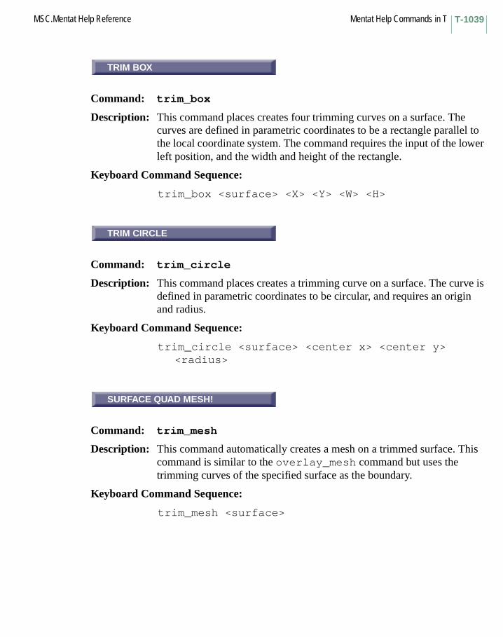
T-1039MSC.Mentat Help Reference Mentat Help Commands in T
TRIM BOX
Command: trim_box
Description: This command places creates four trimming curves on a surface. The curves are defined in parametric coordinates to be a rectangle parallel to the local coordinate system. The command requires the input of the lower left position, and the width and height of the rectangle.
Keyboard Command Sequence:
trim_box <surface> <X> <Y> <W> <H>
TRIM CIRCLE
Command: trim_circle
Description: This command places creates a trimming curve on a surface. The curve is defined in parametric coordinates to be circular, and requires an origin and radius.
Keyboard Command Sequence:
trim_circle <surface> <center x> <center y><radius>
SURFACE QUAD MESH!
Command: trim_mesh
Description: This command automatically creates a mesh on a trimmed surface. This command is similar to the overlay_mesh command but uses the trimming curves of the specified surface as the boundary.
Keyboard Command Sequence:
trim_mesh <surface>
TRIM BOX
TRIM CIRCLE
SURFACE QUAD MESH!

Mentat Help Commands in T MSC.Mentat Help ReferenceT-1040
TRIM OUTER
Command: trim_outer
Description: This command places trimming curves on the edges of surfaces. This is useful when creating trimmed surfaces with holes in them.
Keyboard Command Sequence:
trim_outer <surface list> #
TRIM SURFACES
Command: trim_surfaces
Description: This command places 4 trimming curves on the edges of surfaces.
Keyboard Command Sequence:
trim_surfaces <surface list> #
TRSFAC
Subroutine: TRSFAC
Description: The user subroutine TRSFAC allows you to define a shift function for a particular thermal rheologically simple viscoelastic material group.
TRSFAC is only available in conjunction with the hereditary integral form of viscoelastic constitutive representation.
TRIM OUTER
TRIM SURFACES
TRSFAC

Mentat Help Commands in UUBEAM
Subroutine: UBEAM
Description: The user subroutine UBEAM allows you to define nonlinear elastic cross-section properties as a function of generalized elastic strains and state variables for beam element 52 or beam element 98.
UBEAM is used in conjunction with the hypoelastic option. You must use the HYPOELASTIC model definition option.
U Commands Begin with U
UBEAM
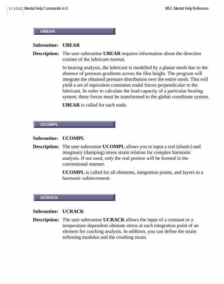
Mentat Help Commands in U MSC.Mentat Help ReferenceU-1042
UBEAR
Subroutine: UBEAR
Description: The user subroutine UBEAR requires information about the direction cosines of the lubricant normal.
In bearing analysis, the lubricant is modelled by a planar mesh due to the absence of pressure gradients across the film height. The program will integrate the obtained pressure distribution over the entire mesh. This will yield a set of equivalent consistent nodal forces perpendicular to the lubricant. In order to calculate the load capacity of a particular bearing system, these forces must be transformed to the global coordinate system.
UBEAR is called for each node.
UCOMPL
Subroutine: UCOMPL
Description: The user subroutine UCOMPL allows you to input a real (elastic) and imaginary (damping) stress strain relation for complex harmonic analysis. If not used, only the real portion will be formed in the conventional manner.
UCOMPL is called for all elements, integration points, and layers in a harmonic subincrement.
UCRACK
Subroutine: UCRACK
Description: The user subroutine UCRACK allows the input of a constant or a temperature dependent ultimate stress at each integration point of an element for cracking analysis. In addition, you can define the strain softening modulus and the crushing strain.
UBEAR
UCOMPL
UCRACK
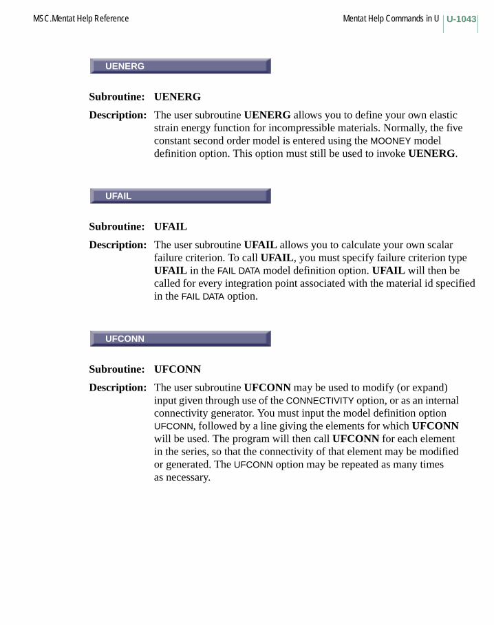
U-1043MSC.Mentat Help Reference Mentat Help Commands in U
UENERG
Subroutine: UENERG
Description: The user subroutine UENERG allows you to define your own elastic strain energy function for incompressible materials. Normally, the five constant second order model is entered using the MOONEY model definition option. This option must still be used to invoke UENERG.
UFAIL
Subroutine: UFAIL
Description: The user subroutine UFAIL allows you to calculate your own scalar failure criterion. To call UFAIL, you must specify failure criterion type UFAIL in the FAIL DATA model definition option. UFAIL will then be called for every integration point associated with the material id specified in the FAIL DATA option.
UFCONN
Subroutine: UFCONN
Description: The user subroutine UFCONN may be used to modify (or expand) input given through use of the CONNECTIVITY option, or as an internal connectivity generator. You must input the model definition option UFCONN, followed by a line giving the elements for which UFCONN will be used. The program will then call UFCONN for each element in the series, so that the connectivity of that element may be modified or generated. The UFCONN option may be repeated as many times as necessary.
UENERG
UFAIL
UFCONN
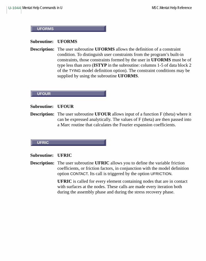
Mentat Help Commands in U MSC.Mentat Help ReferenceU-1044
UFORMS
Subroutine: UFORMS
Description: The user subroutine UFORMS allows the definition of a constraint condition. To distinguish user constraints from the program’s built-in constraints, those constraints formed by the user in UFORMS must be of type less than zero (ISTYP in the subroutine: columns 1-5 of data block 2 of the TYING model definition option). The constraint conditions may be supplied by using the subroutine UFORMS.
UFOUR
Subroutine: UFOUR
Description: The user subroutine UFOUR allows input of a function F (theta) where it can be expressed analytically. The values of F (theta) are then passed into a Marc routine that calculates the Fourier expansion coefficients.
UFRIC
Subroutine: UFRIC
Description: The user subroutine UFRIC allows you to define the variable friction coefficients, or friction factors, in conjunction with the model definition option CONTACT. Its call is triggered by the option UFRICTION.
UFRIC is called for every element containing nodes that are in contact with surfaces at the nodes. These calls are made every iteration both during the assembly phase and during the stress recovery phase.
UFORMS
UFOUR
UFRIC

U-1045MSC.Mentat Help Reference Mentat Help Commands in U
UFRORD
Subroutine: UFRORD
Description: The user subroutine UFRORD may be used to modify (or expand) coordinate change input. You must input the rezoning command UFRORD, followed by a command giving a list of nodes for which UFRORD will be used. The program will then call UFRORD for each node in the list, so that the coordinates for that node may be modified or generated. UFRORD may be repeated as many times as necessary.
UFXORD
Subroutine: UFXORD
Description: The user subroutine UFXORD may be used to modify (or expand) coordinates input through use of the COORDINATE option, or as an internal coordinate generator. You must input the model definition option UFXORD, followed by a line giving the nodes for which UFXORD will be used. The program will then call UFXORD for each node in the list, so that the coordinates of that node may be modified or generated. The UFXORD option may be repeated as many times as necessary.
UGROOV
Subroutine: UGROOV
Description: The user subroutine UGROOV allows you to specify position-dependent groove depths which may need to be included at each integration point in bearing analyses. This allows discontinuous film thicknesses to be applied to increase the load carrying capacity. The grooves may be defined in the GEOMETRY option. UGROOV may also be used for selecting elements which are located at grooves in the event that complex groove patterns have to be modelled.
UGROOV is called for each integration point.
UFRORD
UFXORD
UGROOV

Mentat Help Commands in U MSC.Mentat Help ReferenceU-1046
UHTCOE
Subroutine: UHTCOE
Description: The user subroutine UHTCOE allows you to define variable film coefficients and sink temperatures of free surfaces in conjunction with the options CONTACT and COUPLE. Its call is triggered by the option OHTCOE.
UHTCOE is called at every element surface containing nodes that are on free body boundary, and for each surface at the trapezoidal rule integration points (i.e. the nodes). These calls are made every iteration both during the assembly phase and the recovery phase of the heat transfer pass of a COUPLED analysis.
UHTCON
Subroutine: UHTCON
Description: The user subroutine UHTCON allows you to define variable film coefficients of surfaces that are in contact with other surfaces, in conjunction with the options CONTACT and COUPLE. Its call is triggered by the option OHTCON.
UHTCON is called at every element surface containing nodes that are on free body boundary, and for each surface at the trapezoidal rule integration points (i.e. the nodes). These calls are made every iteration both during the assembly phase and the recovery phase of the heat transfer pass of a COUPLED analysis.
UINSTR
Subroutine: UINSTR
Description: The user subroutine UINSTR is called in a loop over all the elements in the mesh when the ISTRESS option is used. Note that this routine is called twice for each point. During the first call, the user-defined stress vector is used to define the net nodal force. During the second call, the user-defined stress vector is used to define the initial stress at each point.
UHTCOE
UHTCON
UINSTR
U-1047MSC.Mentat Help Reference Mentat Help Commands in U
UMOONY
Subroutine: UMOONY
Description: The user subroutine UMOONY allows you to redefine the constants used in the strain energy function. This data is normally entered through the MOONEY model definition option.
UNALIAS
Command: unalias
Description: This command deletes an alias from the list of aliases.
Keyboard Command Sequence:
unalias <alias name>
UNDEFINE
Command: undefine
Description: This command deletes a parameter from the list of parameters.
Keyboard Command Sequence:
undefine <parameter name>
FULL
Command: undeformed_edges_full
Description: This command specifies that all edges on the outline of the visible portion of undeformed model be displayed.
Keyboard Command Sequence:
undeformed_edges_full
UMOONY
UNALIAS
UNDEFINE
FULL
Mentat Help Commands in U MSC.Mentat Help ReferenceU-1048
OUTLINE
Command: undeformed_edges_outline
Description: This command specifies that only edges on the outline of the visible portion of undeformed model be displayed.
Keyboard Command Sequence:
undeformed_edges_outline
SURFACE
Command: undeformed_edges_surface
Description: This command specifies that only edges on the surface of the visible portion of undeformed model be displayed.
Keyboard Command Sequence:
undeformed_edges_surface
UNDO
Command: UNDO
Description: The command UNDO allows you to cancel the last change made to your model. UNDO works only for actual changes to the model, not for changes made to your view of the model (i.e. UNDO will restore any deleted elements, but will not cancel any rotations or pans).
OUTLINE
SURFACE
UNDO
U-1049MSC.Mentat Help Reference Mentat Help Commands in U
UNEWTN
Subroutine: UNEWTN
Description: The user subroutine UNEWTN allows you to define the viscosity at a particular spatial location when the R-P FLOW option is used to solve Newtonian and Non-Newtonian laminar incompressible fluid analyses. An Eularian approach is then used to solve for the nodal velocities.
UNMAP TRIMMING CURVES
Command: unmap_curves
Description: This command unmaps trimming curves from a chosen surface back to 2-D space. It can help users clean trimming curves manually.
Keyboard Command Sequence:
unmap_curves <surface list>
UNORST
Subroutine: UNORST
Description: The user subroutine UNORST allows you to define the normal stress at each node in contact instead of using the extrapolated value from the integration points.
UNORST is only called for user defined elements and considers the effects of Coulomb friction for CONTACT analysis. The magnitude of the user-defined normal stress must be in the local system of the patch with which the nodal point is in contact.
UNEWTN
UNMAP TRIMMING CURVES
UNORST
Mentat Help Commands in U MSC.Mentat Help ReferenceU-1050
REM
Command: unpost_elements
Description: This command indicates which elements should not be post plotted when a post plotting option is turned on.
Keyboard Command Sequence:
unpost_elements <element list>
REM
Command: unpost_nodes
Description: This command indicates which nodes should not be post plotted when a post plotting option is turned on (for Vectors, Symbols, and Numerics). Normally this is controlled by the unpost_elements command, however, this command allows individual nodes to be controlled. By default, all nodes have been ADDed. Therefore, to view specific nodes use the REM button to remove the nodes that are not to be displayed.
Note that once a node has been removed, it cannot be selected. Therefore, using the ADD button will require that the node numbers be typed in.
Keyboard Command Sequence:
unpost_nodes <node list>
UNTRANSFORM
Command: untransform_nodes
Description: This command clears the transform for the specified list of nodes.
Keyboard Command Sequence:
untransform_nodes <node list> #
REM
REM
UNTRANSFORM

U-1051MSC.Mentat Help Reference Mentat Help Commands in U
UP
Description: This button scrolls the list upward.
update_axito3d
Description: This option allows the axito3d to update load table curves. For applied load, the origin of the table curve coordinate is shifted along the time axis; for displacement boundary condition, the origin is shifted along the curve.
UPDATE
Command: update_job
Description: This command updates the status of the current job.
Keyboard Command Sequence:
update_job
UPDNOD
Subroutine: UPDNOD
Description: The user subroutine UPDNOD is used in conjunction with Eulerian flow solutions (e.g. R-P FLOW) to update the mesh after a velocity field has been found. You may access the velocity field and hence redefine the nodal coordinates.
UPDNOD is called in a loop over all the nodes in the mesh at the end of the convergent step of the flow calculation.
UP
update_axito3d
UPDATE
UPDNOD
Mentat Help Commands in U MSC.Mentat Help ReferenceU-1052
UPHI
Subroutine: UPHI
Description: The user subroutine UPHI allows you to input PHI functions where they can be expressed analytically. The values of PHI are then passed into a routine where they are used in calculation of the Laplace transform for harmonic analysis.
URESTR
Subroutine: URESTR
Description: The user subroutine URESTR allows you to include nonuniform restrictor coefficients and pump pressures, and to modify the restrictor coefficient and pump pressure previously input in the data file.
URESTR is called at each increment for each integration point.
USELEM
Subroutine: USELEM
Description: The user subroutine USELEM allows you to calculate your own finite element stiffness or mass matrix. USELEM may also be used as interface with other numerical techniques.
USELEM is called multiple times for a particular element, since several matrices are generally required in the finite element calculation.
UPHI
URESTR
USELEM

U-1053MSC.Mentat Help Reference Mentat Help Commands in U
CREDE
Subroutine: CREDE
Description: The user subroutine CREDE allows you to input prespecified state variables. The simplest option allows you to specify temperature increments throughout the mesh. Through the use of the STATE VARS parameter line, the number of state variables per point in the structure may be increased. For example, radiation fluxes (in reactor core problems), pore pressures (in soil mechanics) may be included. The program always assumes temperature is the first state variable given at a particular point or since the first state variable is used in conjunction with the tables of temperature dependence input specified in the TEMPERATURE EFFECTS option, and the first state variable is used to compute thermal strains. All state variables are available to all constitutive routines – see subroutines CRPLAW and VSWELL later in this section.
Subroutine CREDE will be called once per element in a loop over the elements when the THERMAL LOADS option is activated.
CRPLAW
Subroutine: CRPLAW
Description: For creep analysis, the user subroutine CRPLAW allows you to specify the creep strain rate. CRPLAW will be called as required during the analysis.
For visco-plasticity analysis, the user subroutine CRPLAW may also be used for calculating the visco-plastic behavior. All the creep quantities are treated as viscoplastic strain quantities when the appropriate flag is set in the CREEP option.
CREDE
CRPLAW
Mentat Help Commands in U MSC.Mentat Help ReferenceU-1054
USER SUB. CRPVIS
Subroutine: CRPVIS
Description: The user subroutine CRPVIS allows you to include a general Kelvin model (in addition to the nonlinear Maxwell-type model allowed in the CREEP option).
CUPFLX
Subroutine: CUPFLX
Description: The user subroutine CUPFLX allows you to modify the default routine for the calculation of the internal heat generated due to inelastic energy dissipation. This routine is only used if a coupled thermal-mechanical analysis is being performed and a distributed FLUX type 101 is chosen.
FILM
Subroutine: FILM
Description: The user subroutine FILM allows you to include nonuniform film coefficients and sink temperatures for the calculation of convection or radiation boundary conditions.
FILM is called at each time step for each integration point on each element surface given in the FILMS model definition set, and allows you to modify the film coefficient and sink temperature.
FLOW
Subroutine: FLOW
Description: The user subroutine FLOW allows you to modify mass flow rate, inlet temperature, and film coefficient in heat transfer analyses involving fluid channel elements. Both the inlet temperature and mass flow rate can be dependent on time; the film coefficient can also be a function of streamline distance.
USER SUB. CRPVIS
CUPFLX
FILM
FLOW

U-1055MSC.Mentat Help Reference Mentat Help Commands in U
FLUX
Subroutine: FLUX
Description: The user subroutine FLUX allows you to specify surface or body fluxes as functions of time, temperature, or position for heat transfer analysis. The use of this subroutine is flagged by the appropriate flux type in the DIST FLUXES or FLUXES input option where the type chosen depends on element type.
FORCDF
Subroutine: FORCDF
Description: The user subroutine FORCDF is used to input frequency dependent point loads or displacement histories. (Use user subroutine FORCEM for distributed loads.)
FORCDF is flagged by introducing a model definition set (FORCDF) listing the node numbers for which this routine is called. Then, at each harmonic increment of the analysis, for each of the nodes on the list, the subroutine is called. Displacement and load arrays are available for stress analysis. For dynamic analysis, velocity, and acceleration are available. For nodes without kinematic boundary conditions, you may define increments of point loads (thus overwriting any point load input in the same nodes in the point loads block). For nodes with kinematic boundary conditions (i.e. listed in the FIXED DISP or DISP CHANGE options) you may define increments of harmonic displacement.
FLUX
FORCDF
Mentat Help Commands in U MSC.Mentat Help ReferenceU-1056
FORCDT
Subroutine: FORCDT
Description: The user subroutine FORCDT is used to input time dependent point loads or displacement histories. (User subroutine FORCEM is used for distributed loads.)
FORCDT is flagged by introducing a model definition set (FORCDT) listing the node numbers for which this routine is called. Then, at each increment of the analysis, for each of the nodes on the list, the subroutine is called. Displacement and load arrays are available for stress analysis. For dynamic analysis, velocity, and acceleration are available. For nodes without kinematic boundary conditions, you may define increments of point loads (thus overwriting any point load input in the same nodes in the point loads block). For nodes with kinematic boundary conditions (i.e. listed in the FIXED DISP or DISP CHANGE options) you may define increments of displacement.
FORCEM
Subroutine: FORCEM
Description: The user subroutine FORCEM is used to input nonuniform distributed loads. This routine may be used to specify the load magnitude as a function of position and/or time.
FORCEM is called during the calculation of the equivalent nodal loads, at each integration point needed to calculate the loads specified in the DIST LOADS. If data blocks are read by the user’s FORCEM, they should therefore appear after the corresponding END OPTION or CONTINUE options in the input deck.
FORCDT
FORCEM

U-1057MSC.Mentat Help Reference Mentat Help Commands in U
GAPT
Subroutine: GAPT
Description: The user subroutine GAPT allows you to redefine gap temperature (TGAP) based on the nodal temperatures T1 and T2 in conjuction with the CONRAD GAP option. If the gap temperature (TGAP) is greater than or equal to the gap closure temperature (TCLOSE), then the gap is closed. Otherwise the gap is open.
GAPU
Subroutine: GAPU
Description: The user subroutine GAPU allows you to input or modify the direction and closure distance of gap element type 12 and 97 based on the current position of the end nodes of the element. This makes it possible to model contact sliding along curved surfaces which may occur in the analysis of metal forming problems. Note that although the gap direction and closing distance can be changed, GAPU does not allow for finite sliding of two meshes with respect to each other, since the load transfer path is unchanged. In addition, GAPU allows for specification of a nonlinear relationship between the normal force and the maximum friction force instead of the regular linear Coulomb relation.
Note: If this option is used to change the direction of the gap, then friction should NOT be included.
GAPU also allows you to specify certain tolerances to control gap closure and friction iterations. Note that this last feature will generally not be used.
GAPT
GAPU
Mentat Help Commands in U MSC.Mentat Help ReferenceU-1058
GENSTR
Subroutine: GENSTR
Description: The user subroutine GENSTR allows you to enter the generalized stress-strain law for shells and beams which are conventionally integrated through their thickness. This is often convenient in composite analysis, where the experimental information is for the total material, not individual plies. GENSTR is activated using the SHELL SECT parameter lines. As no layer integration is performed, the number of layers may be set to one.
HOOKLW
Subroutine: HOOKLW
Description: The user subroutine HOOKLW is an alternative mechanism to user subroutine ANELAS. In this routine, you supply the elastic stress-strain law. This law is given in terms of the coordinate system defined in the ORIENTATION option. You should insure that the stress-strain law is symmetric. Note that this routine will be called for each integration point of those elements that have anisotropic properties. You may define either the stress-strain relation or the compliance strain-stress relation. The returned value of argument IMOD must be set accordingly.
HOOKVI
Subroutine: HOOKVI
Description: The user subroutine HOOKVI allows you to modify the time dependent properties of an orthotropic material specified through the VISCELORTH model definition option.
HOOKVI is automatically called for every material defined in that option.
GENSTR
HOOKLW
HOOKVI

U-1059MSC.Mentat Help Reference Mentat Help Commands in U
HYPELA
Subroutine: HYPELA
Description: The user subroutine HYPELA allows you to define elastic constants as functions of elastic strain and state variables.
INITPL
Subroutine: INITPL
Description: The user subroutine INITPL is called in a loop over all the elements in the mesh when the INITIAL PLASTIC option appears in the model definition options with a 2 in column 10 of the second data blocks of that option. It is often necessary to enter the amount of previously accumulated plastic strain. This initial value is only used in the work (strain) hardening calculation.
INITSV
Subroutine: INITSV
Description: The user subroutine INITSV allows you to define initial values of state variables. This routine will be called in a loop over all the elements in the mesh when the INITIAL STATE option (appears in the model definition options with a 2 in column 10 of the second data blocks of that option).
INTCRD
Subroutine: INTCRD
Description: The user subroutine INTCRD makes the integration point coordinates for the stiffness matrix available at each increment. You may save them in any form convenient for your postprocessing.
HYPELA
INITPL
INITSV
INTCRD
Mentat Help Commands in U MSC.Mentat Help ReferenceU-1060
MOTION
Subroutine: MOTION
Description: The user subroutine MOTION allows you to define nonuniform rigid surface motions, in conjunction with the option CONTACT. Its call is triggered by the model definition option UMOTION.
User subroutine MOTION is called during the calculations at the beginning of each time increment, and you return surface velocities for that increment. Imposed displacement increments at nodal points in contact with rigid surfaces are obtained from the velocity multiplied by the time increment. The surface path becomes an explicit forward integration of velocities. Therefore, caution should be used when there are abrupt changes in surface path direction or abrupt changes in velocity, by making time increments as small as necessary.
If, at the start of the analysis, a surface is placed apart from the body to be deformed, subroutine MOTION will also be used in the approaching phase, in time increments of 0.1 seconds.
NASSOC
Subroutine: NASSOC
Description: The user subroutine NASSOC allows you to calculate a strain increment using a flow rule differing from the normality rule of plasticity, which is the default used by the program.
NEWSV
Subroutine: NEWSV
Description: The user subroutine NEWSV allows you to define the new values of any state variable for the end of the current step. This subroutine will be called in a loop over all the elements in the mesh when requested through the CHANGE STATE option.
MOTION
NASSOC
NEWSV
U-1061MSC.Mentat Help Reference Mentat Help Commands in U
ORIENT
Subroutine: ORIENT
Description: The user subroutine ORIENT allows you to supply a preferred orientation so that ANELAS, HOOKLW, ANPLAS, and ANKOND may supply anisotropic material constants in this orientation.
SEPFOR
Subroutine: SEPFOR
Description: The user subroutine SEPFOR allows you to define the separation force in conjunction with the model definition option CONTACT. The separation forces, FNORM and FTANG, are either calculated by the program or entered through the CONTACT option, and are then passed into this subroutine. You decide whether this magnitude at the current increment is good enough to determine whether separation will occur.
FNORM is the normal reaction force above which a node in contact will separate from a surface. Any compressive or negative value indicates real contact, while a positive reaction force indicates a tendency to separate. The default is taken as the maximum value of the residual force in the structure for the current increment. This value can be reset in the input deck. Defining a small value may result in an increased number of iterations. Defining a very large value will eliminate the possibility of separation.
FTANG is the tangential force used to determine whether a nodal point positioned at a convex corner of a surface should be sliding from patch to patch or remain on its current patch. The default value is half of FNORM. These two default reaction forces vary from increment to increment.
ORIENT
SEPFOR

Mentat Help Commands in U MSC.Mentat Help ReferenceU-1062
SEPSTR
Subroutine: SEPSTR
Description: The user subroutine SEPSTR allows you to define the separation stress in conjunction with the model definition option CONTACT. The separation stresses, SNORM and STANG, are either calculated by the program or entered through the CONTACT option, and are then passed into this subroutine. You decide whether this magnitude at the current increment is good enough to determine whether separation will occur.
SNORM is the stress normal to the surface above which a node in contact will separate from another body. Any compressive or negative value indicates real contact, while a positive reaction stress indicates a tendency to separate. The default is taken as the maximum value of the residual force in the structure for the current increment divided by an effective area. This value can be reset in the input line. Defining a too small value can result in an increased number of iterations. Defining a very large value will eliminate the possibility of separation.
STANG is the tangential stress used to determine whether a nodal point positioned at a convex corner of a surface should be sliding from patch to patch or remain on its current patch. The default value is half of SNORM. These two default values vary from increment to increment.
TRSFAC
Subroutine: TRSFAC
Description: The user subroutine TRSFAC allows you to define a shift function for a particular thermal rheologically simple viscoelastic material group.
TRSFAC is only available in conjunction with the hereditary integral form of viscoelastic constitutive representation.
SEPSTR
TRSFAC

U-1063MSC.Mentat Help Reference Mentat Help Commands in U
UBEAM
Subroutine: UBEAM
Description: The user subroutine UBEAM allows you to define nonlinear elastic cross-section properties as a function of generalized elastic strains and state variables for beam element 52 or beam element 98.
UBEAM is used in conjunction with the hypoelastic option. You must use the HYPOELASTIC model definition option.
UBEAR
Subroutine: UBEAR
Description: The user subroutine UBEAR requires information about the direction cosines of the lubricant normal.
In bearing analysis, the lubricant is modelled by a planar mesh due to the absence of pressure gradients across the film height. The program will integrate the obtained pressure distribution over the entire mesh. This will yield a set of equivalent consistent nodal forces perpendicular to the lubricant. In order to calculate the load capacity of a particular bearing system, these forces must be transformed to the global coordinate system.
UBEAR is called for each node.
UCOMPL
Subroutine: UCOMPL
Description: The user subroutine UCOMPL allows you to input a real (elastic) and imaginary (damping) stress strain relation for complex harmonic analysis. If not used, only the real portion will be formed in the conventional manner.
UCOMPL is called for all elements, integration points, and layers in a harmonic subincrement.
UBEAM
UBEAR
UCOMPL
Mentat Help Commands in U MSC.Mentat Help ReferenceU-1064
UCONTACT
Subroutine: UCONTACT
Description: The user subroutine UCONTACT allows you to calculate your own contact conditions with rigid surfaces based upon the Marc contact algorithm. This subroutine requires the use of the UCONTACT model definition option and is triggered by this option.
In general, the four stages in Marc contact procedures are:
– checking contact– enforce contact constraint– check separation– check penetration.
You can either specify contact conditions at one stage and let the Marc program do the work in the remainder of stages or you can substitute your calculations for all stages.
UCRACK
Subroutine: UCRACK
Description: The user subroutine UCRACK allows the input of a constant or a temperature dependent ultimate stress at each integration point of an element for cracking analysis. In addition, you can define the strain softening modulus and the crushing strain.
UENERG
Subroutine: UENERG
Description: The user subroutine UENERG allows you to define your own elastic strain energy function for incompressible materials. Normally, the five constant second order model is entered using the MOONEY model definition option. This option must still be used to invoke UENERG.
UCONTACT
UCRACK
UENERG
U-1065MSC.Mentat Help Reference Mentat Help Commands in U
UFAIL
Subroutine: UFAIL
Description: The user subroutine UFAIL allows you to calculate your own scalar failure criterion. To call UFAIL, you must specify failure criterion type UFAIL in the FAIL DATA model definition option. UFAIL will then be called for every integration point associated with the material id specified in the FAIL DATA option.
UFCONN
Subroutine: UFCONN
Description: The user subroutine UFCONN may be used to modify (or expand) input given through use of the CONNECTIVITY option, or as an internal connectivity generator. You must input the model definition option UFCONN, followed by a line giving the elements for which UFCONN will be used. The program will then call UFCONN for each element in the series, so that the connectivity of that element may be modified or generated. The UFCONN option may be repeated as many times as necessary.
UFORMS
Subroutine: UFORMS
Description: The user subroutine UFORMS allows the definition of a constraint condition. To distinguish user constraints from the program’s built-in constraints, those constraints formed by the user in UFORMS must be of type less than zero (ISTYP in the subroutine: columns 1-5 of data block 2 of the TYING model definition option). The constraint conditions may be supplied by using the subroutine UFORMS.
UFAIL
UFCONN
UFORMS

Mentat Help Commands in U MSC.Mentat Help ReferenceU-1066
UFOUR
Subroutine: UFOUR
Description: The user subroutine UFOUR allows input of a function F (theta) where it can be expressed analytically. The values of F (theta) are then passed into a Marc routine that calculates the Fourier expansion coefficients.
UFRIC
Subroutine: UFRIC
Description: The user subroutine UFRIC allows you to define the variable friction coefficients, or friction factors, in conjunction with the model definition option CONTACT. Its call is triggered by the option UFRICTION.
UFRIC is called for every element containing nodes that are in contact with surfaces at the nodes. These calls are made every iteration both during the assembly phase and during the stress recovery phase.
UFRORD
Subroutine: UFRORD
Description: The user subroutine UFRORD may be used to modify (or expand) coordinate change input. You must input the rezoning command UFRORD, followed by a command giving a list of nodes for which UFRORD will be used. The program will then call UFRORD for each node in the list, so that the coordinates for that node may be modified or generated. UFRORD may be repeated as many times as necessary.
UFOUR
UFRIC
UFRORD
U-1067MSC.Mentat Help Reference Mentat Help Commands in U
USER SUBROUTINE UFXORD
Subroutine: UFXORD
Description: The user subroutine UFXORD may be used to modify (or expand) coordinates input through use of the COORDINATE option, or as an internal coordinate generator. You must input the model definition option UFXORD, followed by a line giving the nodes for which UFXORD will be used. The program will then call UFXORD for each node in the list, so that the coordinates of that node may be modified or generated. The UFXORD option may be repeated as many times as necessary.
UGROOV
Subroutine: UGROOV
Description: The user subroutine UGROOV allows you to specify position-dependent groove depths which may need to be included at each integration point in bearing analyses. This allows discontinuous film thicknesses to be applied to increase the load carrying capacity. The grooves may be defined in the GEOMETRY option. UGROOV may also be used for selecting elements which are located at grooves in the event that complex groove patterns have to be modelled.
UGROOV is called for each integration point.
UHTCOE
Subroutine: UHTCOE
Description: The user subroutine UHTCOE allows you to define variable film coefficients and sink temperatures of free surfaces in conjunction with the options CONTACT and COUPLE. Its call is triggered by this button.
UHTCOE is called at every element surface containing nodes that are on free body boundary, and for each surface at the trapezoidal rule integration points (i.e. the nodes). These calls are made every iteration, both during the assembly phase and the recovery phase of the heat transfer pass of a COUPLED analysis.
USER SUBROUTINE UFXORD
UGROOV
UHTCOE

Mentat Help Commands in U MSC.Mentat Help ReferenceU-1068
UHTCON
Subroutine: UHTCON
Description: The user subroutine UHTCON allows you to define variable film coefficients of surfaces that are in contact with other surfaces, in conjunction with the options CONTACT and COUPLE. Its call is triggered by this button.
UHTCON is called at every element surface containing nodes that are on free body boundary, and for each surface at the trapezoidal rule integration points (i.e. the nodes). These calls are made every iteration, both during the assembly phase and the recovery phase of the heat transfer pass of a COUPLED analysis.
UINSTR
Subroutine: UINSTR
Description: The user subroutine UINSTR is called in a loop over all the elements in the mesh when the ISTRESS option is used. Note that this routine is called twice for each point. During the first call, the user-defined stress vector is used to define the net nodal force. During the second call, the user-defined stress vector is used to define the initial stress at each point.
UMOONY
Subroutine: UMOONY
Description: The user subroutine UMOONY allows you to redefine the constants used in the strain energy function. This data is normally entered through the MOONEY model definition option.
UHTCON
UINSTR
UMOONY
U-1069MSC.Mentat Help Reference Mentat Help Commands in U
UNEWTN
Subroutine: UNEWTN
Description: The user subroutine UNEWTN allows you to define the viscosity at a particular spatial location when the R-P FLOW option is used to solve Newtonian and Non-Newtonian laminar incompressible fluid analyses. An Eularian approach is then used to solve for the nodal velocities.
UNORST
Subroutine: UNORST
Description: The user subroutine UNORST allows you to define the normal stress at each node in contact instead of using the extrapolated value from the integration points.
UNORST is only called for user defined elements and considers the effects of Coulomb friction for CONTACT analysis. The magnitude of the user-defined normal stress must be in the local system of the patch with which the nodal point is in contact.
UPDNOD
Subroutine: UPDNOD
Description: The user subroutine UPDNOD is used in conjunction with Eulerian flow solutions (e.g. R-P FLOW) to update the mesh after a velocity field has been found. You may access the velocity field and hence redefine the nodal coordinates.
UPDNOD is called in a loop over all the nodes in the mesh at the end of the convergent step of the flow calculation.
UNEWTN
UNORST
UPDNOD
Mentat Help Commands in U MSC.Mentat Help ReferenceU-1070
UPHI
Subroutine: UPHI
Description: The user subroutine UPHI allows you to input PHI functions where they can be expressed analytically. The values of PHI are then passed into a routine where they are used in calculation of the Laplace transform for harmonic analysis.
URESTR
Subroutine: URESTR
Description: The user subroutine URESTR allows you to include nonuniform restrictor coefficients and pump pressures, and to modify the restrictor coefficient and pump pressure previously input in the data file.
URESTR is called at each increment for each integration point.
USELEM
Subroutine: USELEM
Description: The user subroutine USELEM allows you to calculate your own finite element stiffness or mass matrix. USELEM may also be used as interface with other numerical techniques.
USELEM is called multiple times for a particular element, since several matrices are generally required in the finite element calculation.
VSWELL
Subroutine: VSWELL
Description: The user subroutine VSWELL allows you to include pure swelling (dilatational) creep in Marc.
UPHI
URESTR
USELEM
VSWELL
U-1071MSC.Mentat Help Reference Mentat Help Commands in U
WKSLP
Subroutine: WKSLP
Description: The user subroutine WKSLP makes it possible for you to program the yield stress and the corresponding workhardening slope directly as a function of equivalent plastic strain and temperatures. See WORK HARD model definition option. You need to define the value of the slope of the equivalent stress vs. equivalent plastic strain. The current yield stress may be defined also. The specification of the latter is optional. If the value of the current yield is not given here, the program will calculate it from the initial yield value and the workhardening slopes defined in this routine.
YIEL
Subroutine: YIEL
Description: The user subroutine YIEL allows you to define the yield stress based on the current workhardening and other state variables.
ZERO
Subroutine: ZERO
Description: The user subroutine ZERO allows you to calculate the equivalent yield stress based on the current total stresses. The function ZERO in the program applies the von Mises yield criterion as a default. You may substitute another yield criterion by writing a new function ZERO. The MOHRC option should not be used when a new function ZERO is used because of the danger of taking into account the effects of hydrostatic pressure twice.
WKSLP
YIEL
ZERO

Mentat Help Commands in U MSC.Mentat Help ReferenceU-1072
USHELL
Subroutine: USHELL
Description: The user subroutine USHELL allows the specification of the thickness of shell elements for each integration point.
USHELL is called twice for each increment of analysis. It is not advised to change the thickness during an analysis (i.e. after RESTART).
USHRET
Subroutine: USHRET
Description: The user subroutine USHRET allows the definition of the residual shear stiffness for a cracked integration point in a cracking analysis. The factor is defined as the factor with which the initial shear stiffness is multiplied. With this routine, you can define the shear retention factor to be, for instance, a function of the crack strain.
USHRET is automatically called for each existing crack.
USINC
Subroutine: USINC
Description: The user subroutine USINC allows you to input initial displacements and velocities for stress analysis and initial temperatures for heat transfer analysis. You give the values for all degrees of freedom in vector F. This routine is used with either the INITIAL DISPLACEMENTS, INITIAL VELOCITY, or the INITIAL TEMPERATURE option. This routine will be called for every node in the structure if it is used.
USHELL
USHRET
USINC
U-1073MSC.Mentat Help Reference Mentat Help Commands in U
USPRNG
Subroutine: USPRNG
Description: The user subroutine USPRNG allows you to introduce nonlinear spring constants for use with the SPRING and FOUNDATION options, and input of nonlinear damping if the dashpot option is to be used. Your coding must supply both the ratio of the current value of spring stiffness to the data input value and the total spring force.
For dynamic analyses, the ratio of damping coefficient can also be provided. The data value of the spring/dashpot constant, total time, and the element or spring number are made available to the subroutine.
For harmonic analyses, the spring/dashpot constants can be a function of the frequency. USPRNG is accessible whenever either the SPRING or the FOUNDATION option is used.
USSD
Subroutine: USSD
Description: The user subroutine USSD allows you to input the spectral density function for the frequencies required in the spectrum response calculation. These frequencies will be obtained by performing a modal analysis.
UTHICK
Subroutine: UTHICK
Description: The user subroutine UTHICK allows you to define, or to redefine, previously specified nodal thicknesses. In addition, UTHICK may be used to defined thickness increments in incremental analysis or within subincrements when evaluating damping and/or stiffness coefficients. In order to enable the specification of thickness increments as a function of previously calculated bearing properties, you have access to the latter quantities in this routine.
UTHICK is called for each node in the mesh.
USPRNG
USSD
UTHICK
Mentat Help Commands in U MSC.Mentat Help ReferenceU-1074
UTILITY
Menu: UTILS
Description: This menu contains utility Mentat commands.
UTRANS
Subroutine: UTRANS
Description: The user subroutine UTRANS allows the specification of a local coordinate system for user-specified nodes. The node numbers are given in the UTRANFORM model definition option.
UTRANS is called multiple times for each increment of analysis. The local coordinate system can be modified (updated) at each increment to facilitate the input of complex boundary conditions. Incremental nodal displacements and reaction forces will be output in both the local and global coordinate systems. All total nodal quantities will be output in the global system.
UVELOC
Subroutine: UVELOC
Description: The user subroutine UVELOC allows you to specify or redefine previously specified nodal velocity vectors.
UVELOC is called for each node.
UTILITY
UTRANS
UVELOC
Mentat Help Commands in VVERSION
Command: version
Description: This command prints the current version name of the program.
Keyboard Command Sequence:
version
3D
Description: These commands perform the computation of viewfactors for radiation boundary conditions. This computation must be performed before an analysis job is submitted which involves the effects of radiation heat transfer. A file is written containing the viewfactors for this purpose.
The computation of viewfactors is implemented using the Monte Carlo scheme. Rays are emitted randomly from each surface and intersected with every other radiating surface, finding the first intersecting surface for
V Commands Begin with V
VERSION
3D

Mentat Help Commands in V MSC.Mentat Help ReferenceV-1076
each ray. The viewfactor for each incident surface is simply the fraction of emitted rays which have hit that surface.
Commands: vfc_sym_activate <plane>vfc_sym_deactivate <plane>vfc_sym_point <plane> <x y z>vfc_sym_normal <plane> <x y z>
Three symmetry planes, defined by a position and a normal, are provided. Each plane may be individually activated and deactivated.
vfc_type_2dvfc_type_3dvfc_type_ax
The geometry may be interpreted as being two-dimensional, three-dimensional, or axisymmetric. For the two-dimensional and axisymmetric cases, only the element edges which are part of a radiation boundary condition are used in the computation. For three dimensions, only element faces are used.
vfc_nray
This command controls the number or rays emitted by each object. A larger number of emitted rays gives a more accurate estimate of the viewfactor.
vfc_startvfc_stopvfc_reset
These commands control the computation itself. Obviously, vfc_start begins or restarts the computation and vfc_top halts the computation.vfc_reset stops the computation and resets it to the beginning, throwing away all previously computed results. A reset is automatically done whenever any of the above commands is issued.
vfc_file
This command sets the name of the file where the results are to be placed. This must be set before the beginning of viewfactor computation. The format of the file is:
Block 1 – HeaderLine 110 int iver Version #

V-1077MSC.Mentat Help Reference Mentat Help Commands in V
where: out – outer normal of element according to connectivityin – the other side
Notes: For line elements out means the right hand side as you travel from node 1 to node 2.
For shells out is defined by the right hand rule for the connectivity of the nodes. This is the same as the front side in Mentat.
10 int nobj Number of objects10 int nray Number of rays used in computation
Block 2 – ObjectsLine 1 repeated nobj times10 int obj Object number10 int eid Element id10 int face Face or edge number15 float tinf Temperature at infinity top15 float tinf Temperature at infinity bottom
Block 3 – View Factors repeated nobj timesLine 110 int obj Emitting object number10 int nz Number of nonzero viewfactorsLine 2 repeated nz times10 int obj Incident object number15 float vfs[4] Four viewfactors
1234
Emit Incident out out out in in out in in

Mentat Help Commands in V MSC.Mentat Help ReferenceV-1078
LOOKAT POINT DISTANCE
Command: view_lookat_distance
Description: For all active views, this command moves the lookat point to a specified distance from the viewpoint. The lookat point is moved towards or away from the viewpoint along the line which connects them.
This command is useful for changing the depth of the lookat point, so that dynamic rotations will take place about a specified depth. You can use the left mouse button to pick an item which is at the desired depth from your viewpoint.
Keyboard Command Sequence:
view_lookat_distance <distance>view_lookat_distance <ML>
SET ANGLES
Command: view_model_angles
Description: This command sets absolutely the viewing rotation angles for the model, while leaving the viewing model scale and translations alone. All camera settings remain unchanged by this command. You must specify separate X, Y, and Z-rotation angles in degrees.
First, the model is realigned with the view space axes, thus establishing absolutely no rotation for the model. Then the model is rotated about the view space X-axis by the specified X-angle, then rotated about the view space Y-axis by the specified Y-angle, then rotated about the view space Z-axis by the specified Z-angle.
This command acts on all the currently active views.
Also see: activate_view, view_scale_factor, view_model_translation, and the topic viewing for a general discussion of viewing.
Keyboard Command Sequence:
view_model_angles <x angle> <y angle> <z angle>
LOOKAT POINT DISTANCE
SET ANGLES

V-1079MSC.Mentat Help Reference Mentat Help Commands in V
SET TRANSLATION
Command: view_model_translation
Description: This command sets absolutely the viewing translation for the model, while leaving the viewing model scale and rotations alone. All camera settings remain unchanged by this command. You must specify the absolute translation X, Y, and Z in view space from the view space origin. Any preexisting viewing translation is replaced by the given translation.
This command acts on all the currently active views.
Also see: activate_view, view_scale_factor, view_model_angles, and the topic viewing for a general discussion of viewing.
Keyboard Command Sequence:
view_model_translation <x> <y> <z>
ORTHOGRAPHIC
Command: view_orthographic
Description: This command specifies that all active views be displayed with orthographic projection. With orthographic projection, lines that are parallel in the model will appear parallel in the view. Views can be made to be shown in perspective with the view_perspective command.
Views are activated and deactivated with the commands activate_view, deactivate_view, and activate_all_views.
Keyboard Command Sequence:
view_orthographic
SET TRANSLATION
ORTHOGRAPHIC

Mentat Help Commands in V MSC.Mentat Help ReferenceV-1080
PERSPECTIVE
Command: view_perspective
Description: This command specifies that all active views be displayed with perspective projection. With perspective projection, lines that are parallel in the model will appear to converge towards a point at infinity.
Views are activated and deactivated with the commands activate_view, deactivate_view, and activate_all_views.
Keyboard Command Sequence:
view_perspective
SCALE FACTOR
Command: view_scale_factor
Description: This command sets the current viewing scale setting for the model. The scale_model_up and scale_model_down commands will increase or decrease this setting.
This command acts on all the currently active views.
Also see: activate_view, view_scale_factor, view_model_angles, and the topic viewing for a general discussion of viewing.
Keyboard Command Sequence:
view_scale_factor <value>
VIEW SETTINGS
Menu: SETTINGS
Description: This menu contains commands for setting the rotation, translation, and zoom increments.
PERSPECTIVE
SCALE FACTOR
VIEW SETTINGS

V-1081MSC.Mentat Help Reference Mentat Help Commands in V
VIEWPOINT DISTANCE
Command: view_viewpoint_distance
Description: For all active views, this command moves the viewpoint to a specified distance from the lookat point. The viewpoint is moved towards or away from the lookat point along the line which connects them.
You can use the left mouse button to pick an item which is at the desired depth from your lookat point.
Keyboard Command Sequence:
view_viewpoint_distance <distance>view_viewpoint_distance <ML>
ZOOM FACTOR
Command: view_zoom_factor
Description: This command sets the current viewing scale setting for the model. The zoom_model_in and zoom_model_out commands will increase or decrease this setting.
This command acts on all the currently active views.
Also see: activate_view, view_zoom_factor, view_model_angles, and the topic viewing for a general discussion of viewing.
Keyboard Command Sequence:
view_zoom_factor <value>
VIEWPOINT DISTANCE
ZOOM FACTOR
Mentat Help Commands in V MSC.Mentat Help ReferenceV-1082
VIEW
Menu: VIEW
Description: This menu contains commands for changing the view of the model. The viewing commands refer to three different spaces called model space, view space, and camera space.
View space can be thought of as a room containing the model, a virtual camera, and the lights used in lighting and rendering.
Model space is the database space of the model, with the origin always at the model origin, and its axes always aligned with the model’s axes.
Camera space is the space of the graphics window, with its origin at the viewpoint, and Y pointing up, X pointing to the right, and Z pointing out of the screen.
Certain viewing commands move the model around the room (view space), while other commands move the camera around. All the lighting commands which control the location of lights are also referring to view space.
ALL
Command: visible_all
Description: This command makes the all nodes, elements, points, curves, surfaces, and solids visible.
Keyboard Command Sequence: visible_all
CURVES
Command: visible_curves
Description: This command causes the specified curves to be made visible. Curves can be made invisible with the invisible_curves command.
Keyboard Command Sequence: visible_curves <curve list> #
VIEW
ALL
CURVES
V-1083MSC.Mentat Help Reference Mentat Help Commands in V
ELEMENTS
Command: visible_elements
Description: This command causes the specified elements to be made visible. Elements can be made invisible with the invisible_elements command.
Keyboard Command Sequence:
visible_elements
MAKE VISIBLE
Command: visible_selected
Description: This command causes the currently selected entities to be made visible. Selected entities can be made invisible with the invisible_selected command.
Keyboard Command Sequence:
visible_selected
SOLIDS
Command: visible_solids
Description: This command causes the specified solids to be made visible. Solids can be made invisible with the invisible_solids command.
Keyboard Command Sequence:
visible_solids <solid list> #
ELEMENTS
MAKE VISIBLE
SOLIDS
Mentat Help Commands in V MSC.Mentat Help ReferenceV-1084
SURFACES
Command: visible_surfaces
Description: This command causes the specified surfaces to be made visible. Surfaces can be made invisible with the invisible_surfaces command.
Keyboard Command Sequence:
visible_surfaces <surface list> #
VISUALIZATION
Menu: VISUALIZATION
Description: This menu contains menus for PLOT, COLORS, VIEW, LIGHTING, and RENDER settings.
PLOTContains commands for plotting nodes, elements, points, curves, surfaces, solids, cavities, boundary conditions, initial conditions, links, rbe2’s, rbe3’s, material orientations, and loadcases. Elements, surfaces, and solids may be plotted in wireframe or solid mode.
Visibility, opaqueness, and translucency of entities may be specified. The legend toggled on or off, and annotations may be specified at user defined locations.
The identification of backfaces, element classes and types, boundary conditions, initial conditions, inserts, materials, geometric properties, contact bodies, global and local remeshing bodies, domains and sets may be selected.
COLORSThe colors for the background, graphs, annotations, contour lines, grid, points, curves, surfaces, elements, backfaces, boundary conditins, selected entities and attached entities may be specified.
VIEWThis menu contains commands for setting the camera view options, model view options, displaying views 1-4 or showing all views. The view repeat mode, zooming in/out, scaling up/down, and viewing in either orthographic or perspective mode may be specified.
SURFACES
VISUALIZATION
V-1085MSC.Mentat Help Reference Mentat Help Commands in V
LIGHTINGThe light settings (OpenGL version only) may be specified for any of the views. Up to 8 lights may be enabled and their color may be specified. The lights may be static or dynamic, local, infinite, or a spotlight. The light direction may be specified directly or moved using the mouse.
RENDERThis menu contains commands for setting the renderer options, such as renderer resolution, anti-aliasing on/off, anti-aliasing tolerance and depth, pixel size, line and symbol radius. The render view may also be selected and also the image size.
VSWELL
Subroutine: VSWELL
Description: The user subroutine VSWELL allows you to include pure swelling (dilatational) creep in Marc.
VSWELL

Mentat Help Commands in V MSC.Mentat Help ReferenceV-1086
Mentat Help Commands in WWRITE
Command: write_marc
Description: This command writes a Marc input file with data from the current model database. You must specify the name of the file. Conventionally, Marc input file names end with .dat.
Keyboard Command Sequence:
write_marc <MARC file name>
COLOR FILE
Command: write_postscript_color
Description: This command writes a color PostScript file with data currently displayed in the graphics window. You must specify the name of the PostScript file.
Keyboard Command Sequence:
write_postscript_color <file name>
W Commands Begin with W
WRITE
COLOR FILE
Mentat Help Commands in W MSC.Mentat Help ReferenceW-1088
GRAY FILE
Command: write_postscript_gray
Description: This command writes a gray scale PostScript file with data currently displayed in the graphics window. You must specify the name of the PostScript file.
Keyboard Command Sequence:
write_postscript_gray <file name>
GRAY FILE
Mentat Help Commands in XCLEAR CURVES
Command: xcurve_clear
Description: Clear all curves.
Keyboard Command Sequence:
xcurve_clear
BIAXIAL
Command: xcurve_dual_biax
Description: Toggle the plotting of the predicted stress response for the biaxial deformation mode ON/OFF.
Keyboard Command Sequence:
xcurve_dual_biax <on or off>
X Commands Begin with X
CLEAR CURVES
BIAXIAL

Mentat Help Commands in X MSC.Mentat Help ReferenceX-1090
PLANAR SHEAR
Command: xcurve_dual_plshr
Description: Toggle the plotting of the predicted stress response for the planar shear deformation mode ON/OFF.
Keyboard Command Sequence:
xcurve_dual_plshr <on or off>
SIMPLE SHEAR
Command: xcurve_dual_sishr
Description: Toggle the plotting of the predicted stress response for the simple shear deformation mode ON/OFF.
Keyboard Command Sequence:
xcurve_dual_sishr <on or off>
UNIAXIAL
Command: xcurve_dual_uniax
Description: Toggle the plotting of the predicted stress response for the uniaxial deformation mode ON/OFF.
Keyboard Command Sequence:
xcurve_dual_uniax <on or off>
PLANAR SHEAR
SIMPLE SHEAR
UNIAXIAL

X-1091MSC.Mentat Help Reference Mentat Help Commands in X
VOLUMETRIC
Command: xcurve_dual_vol
Description: Toggle the plotting of the predicted stress response for the volumetric deformation mode ON/OFF.
Keyboard Command Sequence:
xcurve_dual_vol <on or off>
SCALE AXES
Command: xcurve_fill
Description: Set both the abscissa and ordinate bounds.
Keyboard Command Sequence:
xcurve_fill
SAVE CURVES
Command: xcurve_save
Description: This command will make a response curve provided by subsequent calibrations to supplant those of an earlier fit.
Keyboard Command Sequence:
xcurve_save <on or off>
APPLY
Command: xcv_apply
Description: This command copies the computed material model coefficients into a material model: it either creates a new one or changes the existing one.
Keyboard Command Sequence:
xcv_apply
VOLUMETRIC
SCALE AXES
SAVE CURVES
APPLY

Mentat Help Commands in X MSC.Mentat Help ReferenceX-1092
V/V0
Command: xcv_biax_vol
Description: Volumetric data of an equibiaxial test can be given as:
• The ratio of the current thickness and the original thickness (t/t0). The button text for this case will be t/t0.
or:
• The ratio of the current volume and the original volume (V/V0). The button text for this case will be V/V0
By default, Mentat expects the volumetric data to be in terms of t/t0. If the actual data is in terms of V/V0, use xcv_biax_vol to switch to this type of input.
Keyboard Command Sequence:
xcv_biax_vol <on or off>
MATHEMATICAL CHECKS
Command: xcv_checks
Description: This command activates mathematical checks for Ogden and Foam materials and causes the data fitter to discard the coefficients when one of the mathematical conditions on them is not satisfied. These conditions are considered to be very strict and at times no set of coefficients may be found, or the fit may be very poor.
Keyboard Command Sequence:
xcv_checks <on/off>
V/V0
MATHEMATICAL CHECKS
X-1093MSC.Mentat Help Reference Mentat Help Commands in X
UNIAXIAL
Command: xcv_color
Description: This command set the red, green, and blue color for the index of the associated Experimental Curve Fitting line.
Keyboard Command Sequence:
color <index> <red> <green> <blue>
Other Buttons with the same description:
BIAXIALPLANAR SHEARSIMPLE SHEARVOLUMETRICCONSTANT STRAIN DAMAGEINCREASING STRAIN DAM.STRESS RELAXATIONBULK RELAXATIONW RELAXATION192-207
COMPUTE
Command: xcv_compute
Description: This command starts the data fitting program with the selected data. Upon fitting, the measured and fitted curves are displayed and the corresponding material model coefficients and the least squares error are reported.For the Mooney-Rivlin, Ogden, Foam, Arruda-Boyce, and Gent models, the response in the modes for which no data is measured, is predicted. Notice that if volumetric data is relevant in order to predict a uniaxial, biaxial or planar shear mode, this is calculated using the constraint of a zero stress component in a direction perpendicular to the direction of the measured stress component. If this calculation fails, the predicted mode will contain zero stresses.
If the data set contains a large number of entries, or if the model is highly nonlinear and/or contains many coefficients, then the fitting procedure may take some time.
UNIAXIAL
COMPUTE
Mentat Help Commands in X MSC.Mentat Help ReferenceX-1094
Since the curve fitting procedure does not use weighting factors per data point, it might be useful to have many data points near regions where an accurate response is desired.
Keyboard Command Sequence:
xcv_compute
EXTRAPOLATE
Command: xcv_extrapolation
Description: For Mooney-Rivlin, Ogden, Foam, Arruda-Boyce, and Gent models, this command gives the possibility to get the response of the material outside the range of measurements. This might be important if the deformations of the structure to be analyzed exceed those of the experiments.The user needs to set the new left and right bounds up to which the extrapolation will be performed.Notice that when volumetric information is provided, outside the range of measurements the volumetric data is calculated based on linear extrapolation using the two closest measured data points.
Keyboard Command Sequence:
xcv_extrapolation <on/off>
Another Button with the same description:
EXTRAPOLATION
CUSTOM - 1
Command: xcv_custom
Description: Customized material model.
Keyboard Command Sequence:
xcv_custom
EXTRAPOLATE
CUSTOM - 1

X-1095MSC.Mentat Help Reference Mentat Help Commands in X
CONTINUOUS DAMAGE
Command: xcv_discontinuous
Description: This command tells the data fitter that one is fitting the data set to the discontinuous damage model. The defauls setting is on. Also it is useful to compare single data set between the two modes. When turned off, it confirms that the correct value for the free energy at maximum strain, has been entered.
Keyboard Command Sequence:xcv_discontinuous <yes or no>
Another Button with the same description:DISCONTINUOUS DAMAGE
FREE ENERGY
Command: xcv_energy
Description: This command enters value of free energy at maximum strain amplitude. This value is needed to calibrate the continuous damage model. The code utilizes this value to calculate the arclength of the strain energy path.
Keyboard Command Sequence:xcv_energy <value>
xcv_err_abs
Command: xcv_err_abs
Description: The least squares error to be minimized during data fitting can be based on absolute or relative errors:* Err_Abs = sum {[data_measured(i)-data_calculated(i)]^2} i* Err_Rel = sum {[1-data_calculated(i)/data_measured(i)]^2} i
This command can be used to switch between relative (default) and absolute errors.
Keyboard Command Sequence: xcv_err_abs <on or off>
CONTINUOUS DAMAGE
FREE ENERGY
xcv_err_abs

Mentat Help Commands in X MSC.Mentat Help ReferenceX-1096
ERROR LIMIT
Command: xcv_err_lim
Description: During curve fitting, an optimal set of material coefficients is searched for using the Downhill Simplex method. If the least squares error (also see xcv_err_abs) corresponding to a set of material coefficients is larger than the error limit, a new minimum will be searched for, unless the maximum number of iterations has been reached (also see xcv_niter).
This command sets the error limit. If, upon fitting, the reported error is larger than the error limit, searching for a new minimum has been terminated due to reaching the maximum number of iterations.
Keyboard Command Sequence: xcv_err_lim <error limit>
SLOW CONVERGENCE
Command: xcv_fast
Description: This command toggles the step size of the trial coefficients between a small and a large value. The default is a large step size. At times, this feature may assist the engineer. Usually there is no perceptible difference.
Keyboard Command Sequence:xcv_fast <yes or no>
FICTIVE POISSON’S RATIO
Command: xcv_fpois
Description: Enter the value for the fictive Poisson’s ratio.
To use this value, the toggle below this button must be turned ON.
This value is to be used if the user is unable to supply volumetric information (the third column of the input table).
Keyboard Command Sequence: xcv_fpois <fictive Poisson’s ratio>
ERROR LIMIT
SLOW CONVERGENCE
FICTIVE POISSON’S RATIO
X-1097MSC.Mentat Help Reference Mentat Help Commands in X
FICTIVE POISSON’S RATIO
Command: xcv_ipois
Description: Toggle this value to ON in order to use the fictive Poisson’s ratio to create volumetric information.
Keyboard Command Sequence:
xcv_ipois <on or off>
LEFT BOUND
Command: xcv_left_bound
Description: Specify the left bound up to which to perform the extrapolation. If the user prescribes a value within the range of the data set, it will be ignored.
Keyboard Command Sequence:
xcv_left_bound <extrapolation left bound>
USE ALL DATA
Command: xcv_mode_all
Description: This command uses all the available data sets in fitting the model.
Keyboard Command Sequence:
xcv_all_modes <on/off>
FICTIVE POISSON’S RATIO
LEFT BOUND
USE ALL DATA
Mentat Help Commands in X MSC.Mentat Help ReferenceX-1098
BIAXIAL
Command: xcv_mode_biaxial
Description: This command uses the available biaxial data set in fitting the model.
If this button is cross-hatched, then the specific test does not have a table associated with it and cannot be selected. Go back to the EXPERIMENTAL DATA FITTING menu and associate a table with the experiment if you wish to activate it.
Keyboard Command Sequence:
xcv_mode biaxial <on/off>
CONSTANT STRAIN
Command: xcv_mode_damage
Description: This command uses the available damage data set in fitting the model.
If this button is cross-hatched, then the specific test does not have a table associated with it and cannot be selected. Go back to the EXPERIMENTAL DATA FITTING menu and associate a table with the experiment if you wish to activate it.
Keyboard Command Sequence:
xcv_mode_damage <on or off>
Another Button with the same description:
INCREASING STRAIN
BIAXIAL
CONSTANT STRAIN

X-1099MSC.Mentat Help Reference Mentat Help Commands in X
PLANAR SHEAR
Command: xcv_mode_planarshear
Description: This command uses the available planar shear data set in fitting the model.
If this button is cross-hatched, then the specific test does not have a table associated with it and cannot be selected. Go back to the EXPERIMENTAL DATA FITTING menu and associate a table with the experiment if you wish to activate it.
Keyboard Command Sequence:
xcv_mode planar_shear <on/off>
RELAXATION
Command: xcv_mode_relaxation
Description: This command uses the available (shear) relaxation data set in fitting the model.
If this button is cross-hatched, then the specific test does not have a table associated with it and cannot be selected. Go back to the EXPERIMENTAL DATA FITTING menu and associate a table with the experiment if you wish to activate it.
Keyboard Command Sequence:
xcv_mode_relaxation <on or off>
PLANAR SHEAR
RELAXATION

Mentat Help Commands in X MSC.Mentat Help ReferenceX-1100
RELAXATION
Command: xcv_mode_relaxation_bulk
Description: This command uses the available (bulk) relaxation data set in fitting the model.
If this button is cross-hatched, then the specific test does not have a table associated with it and cannot be selected. Go back to the EXPERIMENTAL DATA FITTING menu and associate a table with the experiment if you wish to activate it.
Keyboard Command Sequence:
xcv_mode_relaxation_bulk <on or off>
RELAXATION
Command: xcv_mode_relaxation_w
Description: This command uses the available (energy) relaxation data set in fitting the model.
If this button is cross-hatched, then the specific test does not have a table associated with it and cannot be selected. Go back to the EXPERIMENTAL DATA FITTING menu and associate a table with the experiment if you wish to activate it.
Keyboard Command Sequence:
xcv_mode_relaxation_w <on or off>
RELAXATION
RELAXATION

X-1101MSC.Mentat Help Reference Mentat Help Commands in X
SIMPLE SHEAR
Command: xcv_mode_simpleshear
Description: This command uses the available simple shear data set in fitting the model.
If this button is cross-hatched, then the specific test does not have a table associated with it and cannot be selected. Go back to the EXPERIMENTAL DATA FITTING menu and associate a table with the experiment if you wish to activate it.
Keyboard Command Sequence:
xcv_mode simple_shear <on/off>
UNIAXIAL
Command: xcv_mode_uniaxial
Description: This command uses the available uniaxial data set in fitting the model.
If this button is cross-hatched, then the specific test does not have a table associated with it and cannot be selected. Go back to the EXPERIMENTAL DATA FITTING menu and associate a table with the experiment if you wish to activate it.
Keyboard Command Sequence:
xcv_mode uniaxial <on/off>
SIMPLE SHEAR
UNIAXIAL
Mentat Help Commands in X MSC.Mentat Help ReferenceX-1102
VOLUMETRIC
Command: xcv_mode_volumetric
Description: This command uses the available volumetric data set in fitting the model.
If this button is cross-hatched, then the specific test does not have a table associated with it and cannot be selected. Go back to the EXPERIMENTAL DATA FITTING menu and associate a table with the experiment if you wish to activate it. This type of test data cannot be used for Mooney-Rivlin, Arruda-Boyce, and Gent material models.
Keyboard Command Sequence:
xcv_mode volumetric <on/off>
NUMBER OF ITERATIONS
Command: xcv_niter
Description: At times, the data fitter may arrive at coefficients which correspond to a minimum in the objective function, not fulfilling the least squares error limit (also see xcv_err_lim). This command defines how many attempts the program will make to exit the minimum. The maximum number of iterations is 500.
Keyboard Command Sequence:
xcv_niter <number of iterations>
NUMBER OF TERMS
Command: xcv_nterm
Description: This command sets the number of terms in the series expansion used to describe the material model.
Keyboard Command Sequence:
xcv_nterm <number of terms>
VOLUMETRIC
NUMBER OF ITERATIONS
NUMBER OF TERMS

X-1103MSC.Mentat Help Reference Mentat Help Commands in X
V/V0
Command: xcv_plshr_vol
Description: Volumetric data of a planar shear test can be given as:
• The ratio of the current thickness and the original thickness (t/t0). The button text for this case will be t/t0.
or:
• The ratio of the current volume and the original volume (V/V0). The button text for this case will be V/V0.
By default, Mentat expects the volumetric data to be in terms of t/t0. If the actual data is in terms of V/V0, use xcv_plshr_vol to switch to this type of input.
Keyboard Command Sequence:
xcv_plshr_vol <on or off>
POSITIVE COEFFICIENTS
Command: xcv_positive
Description: Since curve fitting is a mathematical operation, the fitted material model coefficients may be physical nonrealistic. This command forces the fitting procedure to return coefficients which are all positive. The quality of the fit may be worse than that without this restriction.
Keyboard Command Sequence:
xcv_positive <on/off>
V/V0
POSITIVE COEFFICIENTS

Mentat Help Commands in X MSC.Mentat Help ReferenceX-1104
EVALUATE
Command: xcv_recalc
Description: This option prompts the user to enter the coefficients of the material model and displays the response curves. Notice that, although no fit is performed, at least one set of test data must be selected. This feature is available for the Mooney-Rivlin, Ogden, Foam, Arruda-Boyce, and Gent material models.
Keyboard Command Sequence:
xcv_recalc <coefficients of material model>
RESET
Command: xcv_reset
Description: This command resets the experimental data fitting parameters to their default values and clears the results.
Keyboard Command Sequence:
xcv_reset
RIGHT BOUND
Command: xcv_right_bound
Description: Specify the right bound up to which to perform the extrapolation. If the user prescribes a value within the range of the data set, it will be ignored.
Keyboard Command Sequence:
xcv_right_bound <extrapolation right bound>
EVALUATE
RESET
RIGHT BOUND

X-1105MSC.Mentat Help Reference Mentat Help Commands in X
UNIAXIAL
Command: xcv_table
Description: Associate a table with the specified test. Depending on the test data, the table should contain the following data:
• For time independent elastomeric materials (uniaxial, biaxial, planar shear, simple shear, and volumetric test):
eng. strain_1, eng. stress_1, volumetric data_1
eng. strain_2, eng. stress_2, volumetric data_2 . . . . . . . . .eng. strain_n, eng. stress_n, volumetric data_n
If, for uniaxial, biaxial or planar shear data, the third column is left empty, the material is assumed to be incompressible.
• For continuous damage (resulting from a constant strain amplitude test):
cycle_1, str_energy_d_1
cycle_2, str_energy_d_2 . . . . . .cycle_n, str_energy_d_n
In addition, before fitting the data, the free energy (which is the strain energy density corresponding to the undamaged state) is required. Notice that the data points should not include the range of cycles at which damage did not start to evaluate.
• For discontinuous damage (resulting from an increasing strain amplitude test):
str_energy_d_1, strain_energy_d_1/str_energy_d_1_undamaged
str_energy_d_2, strain_energy_d_2/str_energy_d_2_undamaged . . . . . . . . .str_energy_d_n, strain_energy_d_n/str_energy_d_n_undamaged
Notice that the data points should not include the range of cycles at which damage did not start to evaluate.
UNIAXIAL
Mentat Help Commands in X MSC.Mentat Help ReferenceX-1106
• For viscoelastic material behavior (shear relaxation, bulk relaxation, and energy relaxation test):
time_1, value_1 (shear modulus, bulk modulus or strain energy)
time_2, value_2 (shear modulus, bulk modulus or strain energy) . . . . . . . . .time_n, value_n (shear modulus, bulk modulus or strain energy)
Keyboard Command Sequence:
xcv_table <data fit mode> <table name>
Other Buttons with the same description:
BIAXIALPLANAR SHEARSIMPLE SHEARVOLUMETRICBULK RELAX.CONSTANTENERGY RELAX.INCREASINGSHEAR RELAX.
CONVERGENCE TOLERANCE
Command: xcv_tol
Description: The data fitter uses the Downhill Simplex method to find a (local) minimum. This method uses several sets of material coefficients and calculates the corresponding objective functions. Based on the values of the objective functions, the sets of material coefficients are modified. This process is terminated when:
2*abs{(fh-fl)/(abs(fh)+abs(fl))} < convergence tolerance
in which fh is the highest and fl is the lowest objective function found so far. The process is also terminated after 2000 trials if the convergence tolerance has not been reached. This command sets the convergence tolerance.
Keyboard Command Sequence:
xcv_tol <convergence tolerance>
CONVERGENCE TOLERANCE

X-1107MSC.Mentat Help Reference Mentat Help Commands in X
A/A0
Command: xcv_uniax_vol
Description: Volumetric data of a uniaxial test can be given as:
• The ratio of the current cross sectional area and the original cross sectional area (A/A0).
or:
• The ratio of the current volume and the original volume (V/V0).
By default, Mentat expects the volumetric data to be in terms of A/A0. If the actual data is in terms of V/V0, use xcv_uniax_vol to switch to this type of input.
Keyboard Command Sequence:
xcv_mode_damage <on or off>
Another Button with the same description:
V/V0
XDUMP 1
Command: xdump
Description: This command dumps the invokes of the Xwindow dumper from within Mentat. The utility uses the Xwindows utilities xwd and xpr. The xwd utility is invoked from the xdump.gen script located in the tools directory.
After you enter the xdump command you will have five seconds to refresh the display and click on the window you wish to dump. If everything is set up correctly, your window’s contents will be printed on the device connected to your system.
IMPORTANT:The xdump.gen script must be tailored to your specific hardware and software environment by someone who is familiar with the use of shell scripts and redirection of I/O to ports or to devices on a network. Since the specifics of such environments are often very complicated, we cannot supply a definitive set of tools for general use.
A/A0
XDUMP 1

Mentat Help Commands in X MSC.Mentat Help ReferenceX-1108
Keyboard Command Sequence:
xdump1
Another Button with the same description:
XDUMP 2
CURVES
Command: set_xy_draw_crv_histplot curve_type
Description: This command sets the curve type for history plot.
Keyboard Command Sequence:
set_xy_draw_crv_histplot <curve or bar or scatter>
Other Buttons with the same description:
BARSSCATTER
CURVES
Command: set_xy_draw_crv_pathplot curve_type
Description: This command sets the curve type for path plot.
Keyboard Command Sequence:
set_xy_draw_crv_pathplot <curve or bar or scatter>
Other Buttons with the same description:
BARSSCATTER
CURVES
CURVES
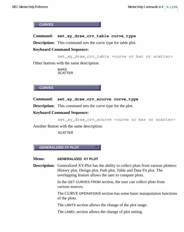
X-1109MSC.Mentat Help Reference Mentat Help Commands in X
CURVES
Command: set_xy_draw_crv_table curve_type
Description: This command sets the curve type for table plot.
Keyboard Command Sequence:
set_xy_draw_crv_table <curve or bar or scatter>
Other buttons with the same description:
BARSSCATTER
CURVES
Command: set_xy_draw_crv_xcurve curve_type
Description: This command sets the curve type for the plot.
Keyboard Command Sequence:
set_xy_draw_crv_xcurve <curve or bar or scatter>
Another Button with the same description:
SCATTER
GENERALIZED XY PLOT
Menu: GENERALIZED XY PLOT
Description: Generalized XY-Plot has the ability to collect plots from various plotters: History plot, Design plot, Path plot, Table and Data Fit plot. The overlapping feature allows the user to compare plots.
In the GET CURVES FROM section, the user can collect plots from various sources.
The CURVE OPERATIONS section has some basic manipulation functions of the plots.
The LIMITS section allows the change of the plot range.
The LABEL section allows the change of plot setting.
CURVES
CURVES
GENERALIZED XY PLOT

Mentat Help Commands in X MSC.Mentat Help ReferenceX-1110
CURVES
Command: xy_plot_draw_crv curve_type
Description: This command sets the curve type for the plot.
Keyboard Command Sequence:
xy_plot_draw_crv_xy_plot <curves or bar or scatter>
Other Buttons with the same description:
BARSSCATTER
FILLED
Command: xy_plot_filledxy_plot_unfilled
Description: These commands specify whether or not areas under tabular functions be filled with color.
Keyboard Command Sequence:
xy_plot_filledxy_plot_unfilled
FIT
Command: xy_plot_fit
Description: This command adjusts the limits of the current plots so that all point values fit within those limits.
Keyboard Command Sequence:
xy_plot_fit
CURVES
FILLED
FIT

X-1111MSC.Mentat Help Reference Mentat Help Commands in X
HISTORY PLOT
Command: get_history_plots
Description: This command sends all of the plots in the respective plotter to the Generalized XY plotter. Here are the respective plotters:
Keyboard Command Sequence:
get_history_plotsget_path_plotsget_opt_plotsget_table_plotsget_xcurve_plots
Other Buttons with the same description:
PATHDESIGN PLOTTABLE PLOTEXPERIMENTAL DATA FIT
Button Command
HISTORY get_history_plots
PATH get_path_plots
RESPONSE GRAD/DESIGN VAR get_opt_plots
TABLE get_table_plots
EXPERIMENTAL DATA FIT get_xcurve_plots
HISTORY PLOT
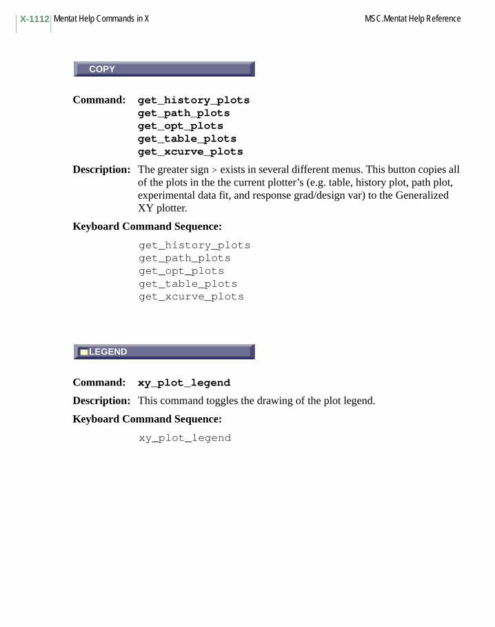
Mentat Help Commands in X MSC.Mentat Help ReferenceX-1112
COPY
Command: get_history_plotsget_path_plotsget_opt_plotsget_table_plotsget_xcurve_plots
Description: The greater sign > exists in several different menus. This button copies all of the plots in the the current plotter’s (e.g. table, history plot, path plot, experimental data fit, and response grad/design var) to the Generalized XY plotter.
Keyboard Command Sequence:
get_history_plotsget_path_plotsget_opt_plotsget_table_plotsget_xcurve_plots
LEGEND
Command: xy_plot_legend
Description: This command toggles the drawing of the plot legend.
Keyboard Command Sequence:
xy_plot_legend
COPY
LEGEND
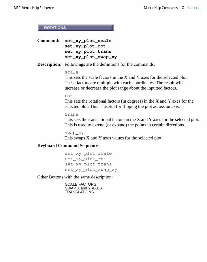
X-1113MSC.Mentat Help Reference Mentat Help Commands in X
ROTATIONS
Command: set_xy_plot_scaleset_xy_plot_rotset_xy_plot_transset_xy_plot_swap_xy
Description: Followings are the definitions for the commands.
scaleThis sets the scale factors in the X and Y axes for the selected plot. These factors are multiple with each coordinates. The result will increase or decrease the plot range about the inputted factors.
rotThis sets the rotational factors (in degrees) in the X and Y axes for the selected plot. This is useful for flipping the plot across an axis.
transThis sets the translational factors in the X and Y axes for the selected plot. This is used to extend (or expand) the points in certain directions.
swap_xyThis swaps X and Y axes values for the selected plot.
Keyboard Command Sequence:
set_xy_plot_scaleset_xy_plot_rotset_xy_plot_transset_xy_plot_swap_xy
Other Buttons with the same description:
SCALE FACTORSSWAP X and Y AXESTRANSLATIONS
ROTATIONS

Mentat Help Commands in X MSC.Mentat Help ReferenceX-1114
CLEAR
Command: xy_plot_copyxy_plot_removexy_plot_clearcopy_to_clipboard
Description: Followings are the definitions for the commands.
Keyboard Command Sequence: xy_plot_copyxy_plot_removexy_plot_clearcopy_to_clipboard
RESET
Command: xy_plot_reset_label
Description: This command resets the title of the plot, the name of the X-axis and the name of the Y-axis to their default values.
Keyboard Command Sequence: xy_plot_reset_label
SHOW XY PLOT
Command: show_xy_plot
Description: This command specifies that the XY Plot is to be displayed. It is particularly useful for toggling between different plot settings.
Keyboard Command Sequence: show_xy_plot
CLEAR
copy Duplicating a plot.
remove Deleting a plot.
clear Delete all plots.
copy_to_clipboard On NT, copy the tabular data to the OS’s clipboard.
RESET
SHOW XY PLOT
Y Commands Begin with Y

Mentat Help Commands in Y MSC.Mentat Help ReferenceY-1116
Mentat Help Commands in YYEOH
Command: xcv_model yeoh
Description: This command is used if experimental data must be fitted using the Yeoh strain energy function W, which is given by:
W = C10*(I1 - 3) + C20*(I1 - 3)^2 + C30*(I1 - 3)^3
where I1 is the first invariant of the right Cauchy-Green strain tensor and C10, C20, and C30 are the material parameters to be determined.
For this model, a volumetric test cannot be supplied. The user may enter a bulk modulus (material_type mechanical: mooney). If no bulk modulus is given, Marc assumes (nearly) incompressible material behavior.
Keyboard Command Sequence:
xcv_model yeoh
YIEL
Subroutine: YIEL
Description: The user subroutine YIEL allows you to define the yield stress based on the current workhardening and other state variables.
YEOH
YIEL

Mentat Help Commands in ZZERO
Subroutine: ZERO
Description: The user subroutine ZERO allows you to calculate the equivalent yield stress based on the current total stresses. The function ZERO in the program applies the von Mises yield criterion as a default. You may substitute another yield criterion by writing a new function ZERO. The MOHRC option should not be used when a new function ZERO is used because of the danger of taking into account the effects of hydrostatic pressure twice.
Z Commands Begin with Z
ZERO
Mentat Help Commands in Z MSC.Mentat Help ReferenceZ-1118
ZOOM BOX
Command: zoom_box
Description: This command zooms in on the selected portion of the model.
Keyboard Command Sequence:
zoombox <use mouse to select box coordinates>
IN
Command: zoom_in
Description: This command zooms in all active views using the current zoom increment set by the zoom_increment command. Zooming in multiplies the views’ zoom factors by the zoom increment.
Keyboard Command Sequence:
zoom_in
Another Button with the same description:
ZOOM IN
ZOOM
Command: zoom_increment
Description: This command sets the zoom factor used by the commands zoom_in and zoom_out.
Keyboard Command Sequence:
zoom_increment <zoom increment>
ZOOM BOX
IN
ZOOM
Z-1119MSC.Mentat Help Reference Mentat Help Commands in Z
OUT
Command: zoom_out
Description: This command zooms out all active views using the current zoom increment set by the zoom_increment command. Zooming out divides the views’ zoom factors by the zoom increment.
Keyboard Command Sequence:
zoom_out
Another Button with the same description:
ZOOM OUT
OUT

Mentat Help Commands in Z MSC.Mentat Help ReferenceZ-1120
Appendix A: MSC.Marc Mentat Arithmetic and Database Functions
APPENDIX
A MSC.Marc Mentat Arithmetic and Database Functions
■ Arithmetic and Database Functions
❑ Arithmetic Functions❑ Database Functions❑ Post File Database Functions❑ Set Functions
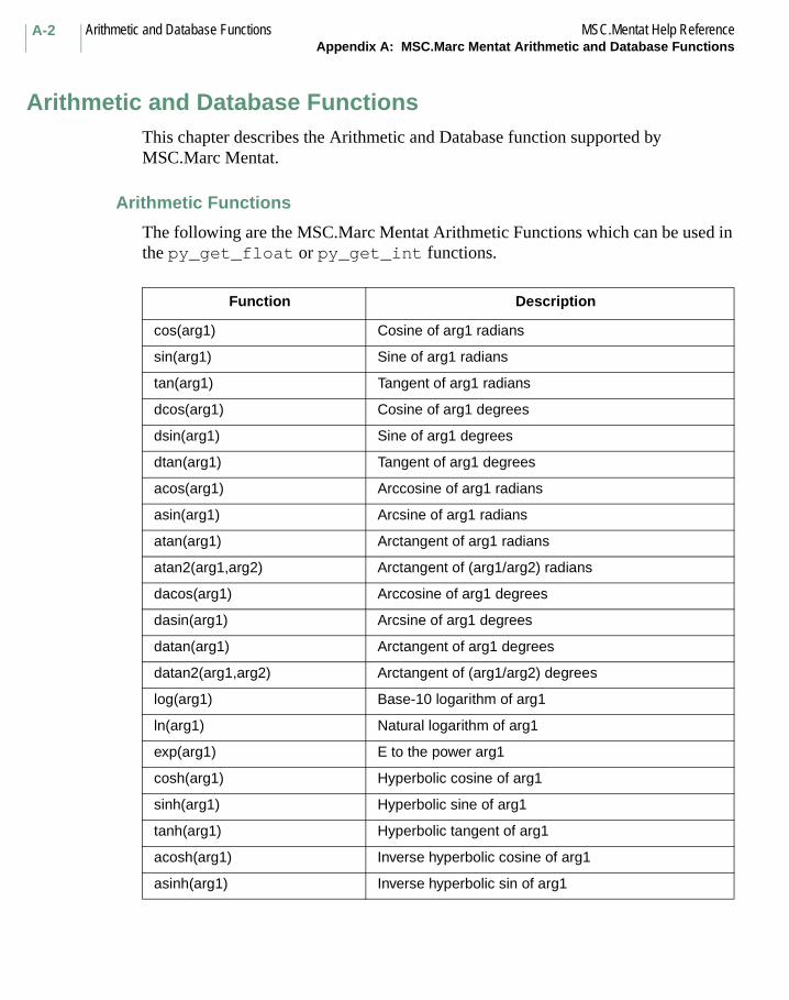
Arithmetic and Database Functions MSC.Mentat Help ReferenceAppendix A: MSC.Marc Mentat Arithmetic and Database Functions
A-2
Arithmetic and Database FunctionsThis chapter describes the Arithmetic and Database function supported by MSC.Marc Mentat.
Arithmetic Functions
The following are the MSC.Marc Mentat Arithmetic Functions which can be used in the py_get_float or py_get_int functions.
Function Description
cos(arg1) Cosine of arg1 radians
sin(arg1) Sine of arg1 radians
tan(arg1) Tangent of arg1 radians
dcos(arg1) Cosine of arg1 degrees
dsin(arg1) Sine of arg1 degrees
dtan(arg1) Tangent of arg1 degrees
acos(arg1) Arccosine of arg1 radians
asin(arg1) Arcsine of arg1 radians
atan(arg1) Arctangent of arg1 radians
atan2(arg1,arg2) Arctangent of (arg1/arg2) radians
dacos(arg1) Arccosine of arg1 degrees
dasin(arg1) Arcsine of arg1 degrees
datan(arg1) Arctangent of arg1 degrees
datan2(arg1,arg2) Arctangent of (arg1/arg2) degrees
log(arg1) Base-10 logarithm of arg1
ln(arg1) Natural logarithm of arg1
exp(arg1) E to the power arg1
cosh(arg1) Hyperbolic cosine of arg1
sinh(arg1) Hyperbolic sine of arg1
tanh(arg1) Hyperbolic tangent of arg1
acosh(arg1) Inverse hyperbolic cosine of arg1
asinh(arg1) Inverse hyperbolic sin of arg1
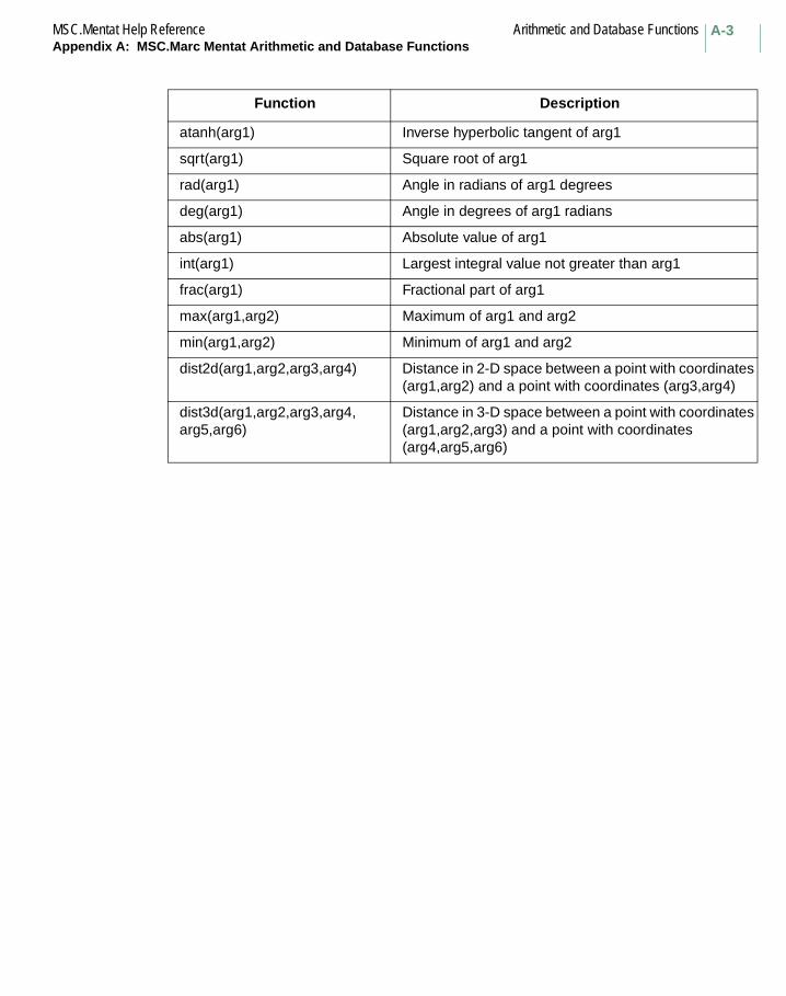
A-3MSC.Mentat Help Reference Arithmetic and Database FunctionsAppendix A: MSC.Marc Mentat Arithmetic and Database Functions
Function Description
atanh(arg1) Inverse hyperbolic tangent of arg1
sqrt(arg1) Square root of arg1
rad(arg1) Angle in radians of arg1 degrees
deg(arg1) Angle in degrees of arg1 radians
abs(arg1) Absolute value of arg1
int(arg1) Largest integral value not greater than arg1
frac(arg1) Fractional part of arg1
max(arg1,arg2) Maximum of arg1 and arg2
min(arg1,arg2) Minimum of arg1 and arg2
dist2d(arg1,arg2,arg3,arg4) Distance in 2-D space between a point with coordinates (arg1,arg2) and a point with coordinates (arg3,arg4)
dist3d(arg1,arg2,arg3,arg4,arg5,arg6)
Distance in 3-D space between a point with coordinates (arg1,arg2,arg3) and a point with coordinates (arg4,arg5,arg6)
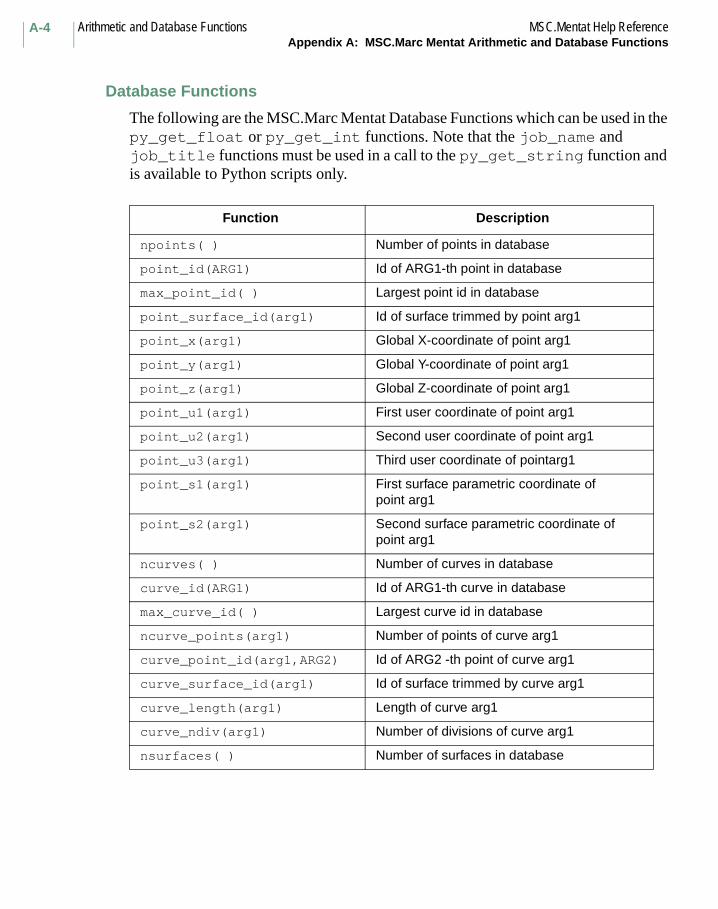
Arithmetic and Database Functions MSC.Mentat Help ReferenceAppendix A: MSC.Marc Mentat Arithmetic and Database Functions
A-4
Database Functions
The following are the MSC.Marc Mentat Database Functions which can be used in the py_get_float or py_get_int functions. Note that the job_name and job_title functions must be used in a call to the py_get_string function and is available to Python scripts only.
Function Description
npoints( ) Number of points in database
point_id(ARG1) Id of ARG1-th point in database
max_point_id( ) Largest point id in database
point_surface_id(arg1) Id of surface trimmed by point arg1
point_x(arg1) Global X-coordinate of point arg1
point_y(arg1) Global Y-coordinate of point arg1
point_z(arg1) Global Z-coordinate of point arg1
point_u1(arg1) First user coordinate of point arg1
point_u2(arg1) Second user coordinate of point arg1
point_u3(arg1) Third user coordinate of pointarg1
point_s1(arg1) First surface parametric coordinate of point arg1
point_s2(arg1) Second surface parametric coordinate of point arg1
ncurves( ) Number of curves in database
curve_id(ARG1) Id of ARG1-th curve in database
max_curve_id( ) Largest curve id in database
ncurve_points(arg1) Number of points of curve arg1
curve_point_id(arg1,ARG2) Id of ARG2 -th point of curve arg1
curve_surface_id(arg1) Id of surface trimmed by curve arg1
curve_length(arg1) Length of curve arg1
curve_ndiv(arg1) Number of divisions of curve arg1
nsurfaces( ) Number of surfaces in database
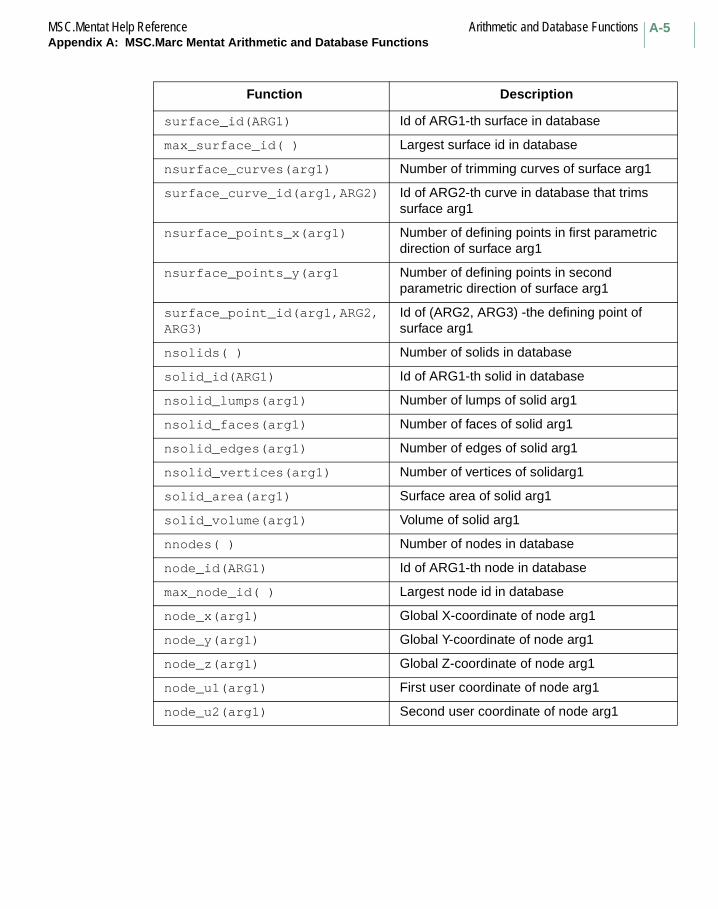
A-5MSC.Mentat Help Reference Arithmetic and Database FunctionsAppendix A: MSC.Marc Mentat Arithmetic and Database Functions
Function Description
surface_id(ARG1) Id of ARG1-th surface in database
max_surface_id( ) Largest surface id in database
nsurface_curves(arg1) Number of trimming curves of surface arg1
surface_curve_id(arg1,ARG2) Id of ARG2-th curve in database that trims surface arg1
nsurface_points_x(arg1) Number of defining points in first parametric direction of surface arg1
nsurface_points_y(arg1 Number of defining points in second parametric direction of surface arg1
surface_point_id(arg1,ARG2,ARG3)
Id of (ARG2, ARG3) -the defining point of surface arg1
nsolids( ) Number of solids in database
solid_id(ARG1) Id of ARG1-th solid in database
nsolid_lumps(arg1) Number of lumps of solid arg1
nsolid_faces(arg1) Number of faces of solid arg1
nsolid_edges(arg1) Number of edges of solid arg1
nsolid_vertices(arg1) Number of vertices of solidarg1
solid_area(arg1) Surface area of solid arg1
solid_volume(arg1) Volume of solid arg1
nnodes( ) Number of nodes in database
node_id(ARG1) Id of ARG1-th node in database
max_node_id( ) Largest node id in database
node_x(arg1) Global X-coordinate of node arg1
node_y(arg1) Global Y-coordinate of node arg1
node_z(arg1) Global Z-coordinate of node arg1
node_u1(arg1) First user coordinate of node arg1
node_u2(arg1) Second user coordinate of node arg1

Arithmetic and Database Functions MSC.Mentat Help ReferenceAppendix A: MSC.Marc Mentat Arithmetic and Database Functions
A-6
Function Description
node_u3(arg1) Third user coordinate of node arg1
nelements( ) Number of elements in database
element_id(ARG1) Id of ARG1-th element in database
max_element_id( ) Largest element id in database
element_node_id(arg1,ARG2) Id of ARG2-th node of element arg1
job_name( ) Name of the job (py_get_string only).
job_title( ) Title of the job (py_get_string only)

A-7MSC.Mentat Help Reference Arithmetic and Database FunctionsAppendix A: MSC.Marc Mentat Arithmetic and Database Functions
Post File Database Functions
The following are the MSC.Marc Post File Database Functions which can be used in the py_get_float or py_get_int functions.
Function Description
displace_x(arg1) Global X displacement of node arg1
displace_y(arg1) Global Y displacement of node arg1
displace_z(arg1) Global Z displacement of node arg1
post_increments() If a post file is opened, it returns the number of increments in the post file.
post_node_extra(arg1) Returns 1 if node arg1 is an extra (dummy) node, 0 if a valid node
scalar_1(arg1) First scalar component of node arg1
scalar_2(arg1) Second scalar component of node arg1
scalar_max_element() Returns the first element in which the scalar quantity is the maximum value.
scalar_min_element() Returns the first element in which the scalar quantity is the minimum value.
scalar_max_node() Returns the first node in which the scalar quantity is the maximum value.
scalar_min_node() Returns the first node in which the scalar quantity is the minimum value.
scalar_pos(x,y,z) Returns the value of the scalar quantity that is being postprocessed at position (x,y,z), if that position is located somewhere in the finite element mesh or 0 if the position is outside the finite element mesh. The value is obtained by interpolating the closest element.

Arithmetic and Database Functions MSC.Mentat Help ReferenceAppendix A: MSC.Marc Mentat Arithmetic and Database Functions
A-8
Set Functions
The following are the MSC.Marc Mentat Set functions, available to Python scripts only, which can be used in a call to the py_get_float or py_get_int functions. The set_name and set_type functions must be used in a call to the py_get_string function.
Function Description
is_curve_set(arg1) Returns 1 if set arg1 is a curve set, 0 otherwise.
is_edge_set(arg1) Returns 1 if set arg1 is a edge set, 0 otherwise.
is_element_set(arg1) Returns 1 if set arg1 is a element set, 0 otherwise.
is_face_set(arg1) Returns 1 if set arg1 is a face set, 0 otherwise.
is_node_set(arg1) Returns 1 if set arg1 is a node set, 0 otherwise.
is_point_set(arg1) Returns 1 if set arg1 is a point set, 0 otherwise.
is_surface_set(arg1) Returns 1 if set arg1 is a surface set, 0 otherwise.
nsets() Number of sets in database
nset_entries(arg1) Number of set entries for set arg1
set_edge(arg1, ARG2) The id of the ARG2-th edge set entry in edge set arg1.
set_entry(arg1, ARG2) The value of the ARG2-th set entry in set arg1.
set_face(arg1, ARG2) The id of the ARG2-th face set entry in face set arg1.
set_id(ARG1) Id of ARG1-th set in database
set_name(arg1) Name of set arg1. This is a string value, and can only be used in py_get_string.
set_type(arg1) Type of set arg1. This is a string value, and can only be used in py_get_string. Returned values will be one of the following strings: node, element, point, edge, curve, face, surface.


