Publication 246D-EN – September 2017
Setup and Operating Instructions
MPT Electric Fire Pump Controller
This manual provides general information, installation, operation, maintenance,
and system setup information for Metron MPT Electric Fire Pump Controllers
and MPT Electric Fire Pump Controllers with Metron Transfer Switch.
Section Page
Introduction 3
Installation 4
Operator Interface Device (OID) Use and Navigation 9
Set Point List 16
Test Procedure 18
Disposal 22
Replacement Parts & Technical Support 23
2 MPT Electric Fire Pump Controller
Publication 246D-EN – September 2017
History of Changes
Rev. No. Date Description of Changes
A October 2015 Initial Release
B July 2016 Added “Unloaded Run Time” set point.
C October 2016 Update text so manual can be used with non-
MTS controllers
Changed “Alternate” to “Emergency”
Removed “top entry” restriction
D September 2017 Updated Eledyne contact info
MPT Electric Fire Pump Controller 3
Publication 246D-EN – September 2017
Introduction Metron MPT Electric Fire Pump Controllers are microprocessor based
controllers intended for use with electric motor driver fire pumps. The
controller's purpose is to automatically start the fire pump electric motor upon a
drop in pressure in the water main or from a number of other demand signals.
The MPT provides alarm and/or alarm shutdown protection for various motor
and power failures. Stopping the motor after the demand period is over may be
performed either manually or automaticly.
Approvals
Metron MPT controllers are listed by Underwriter's Laboratories, Inc., in
accordance with UL218, Standard for Industrial Controls; and CSA, Standard
for Industrial Control Equipment (cUL); and Approved by Factory Mutual and
New York City. They are built to meet or exceed the requirments of NFPA 20
(Installation of Centrifugal Fire Pumps).
NOTICE Read these instructions thoroughly before
installing and operating the controller. If there
are still questions, contact your Metron factory
representative for assistance.
4 MPT Electric Fire Pump Controller
Publication 246D-EN – September 2017
Installation The controller has been assembled and wired at the factory with the highest
workmanship standards. All wiring and functions have been thoroughly tested to
ensure correct operation when properly installed. The installed should be
completely familiar with the external hookup of the pump junction box to the
fire pump controller. All national and local electric codes should be used for
proper installation, wiring, and grounding of the controller prior to startup.
Receiving, Handling, and Storage
1. Immediately upon receipt, carefully unpack and inspect the controller
for damage that may have occurred in shipment. If damage or rough
handling is evident, file a damage claim with the transportation carrier
immediately.
2. If the controller must be stored, cover it and then place it in a clean, dry
location. Avoid unheated locations, where condensation can result in
damage to the insulation or corrosion of metal parts.
Precautions
CAUTION To avoid risk of SERIOUS INJURY or DEATH, and to
avoid damage to the controller, READ THIS SECTION
CAREFULLY. If questions or concerns still exist,
contact the Metron factory for further
clarification.
ARC FLASH
HAZARD
Do not operate controls or open covers without
appropriate personal protection equipment.
Failure to comply may result in SERIOUS INJURY
or DEATH! Refer to NFPA70E for PPE requirements.
If work must be carried out on the motor or controller, ensure the controller is
ISOLATED AND LOCKED OFF from the AC mains supply before work
commences. Lockout/Tag out procedures should be followed in accordance
with NFPA standard and any local standards that may apply.
During installation and maintenance, to prevent automatic starting of the motor
press and hold the S T O P key. The system will be in a configuration mode and
MPT Electric Fire Pump Controller 5
Publication 246D-EN – September 2017
will not start the motor. Configuration mode will last for five (5) minutes, unless
the on-screen "Exit Config Mode" button is pressed.
Installation Instructions
Mounting The controller should be mounted using appropriate fixing methods:
A. If the controller is mounted directly to the pump skid, anti-vibration
mounts should be used.
B. If the controller is mounted to a wall, it should use the four (4) external
mounting holes of the controller cabinet. Suitable fixings to the wall
should be used taking into consideration the weight of the controller. It
is recommended that the controller be mounted at least 12 inches
(300mm) above floor level.
Electrical Connections
DANGER
SHOCK HAZARD
Electric shock may result in SERIOUS INJURY
OR DEATH. Electrical connections should be
made by a qualified electrical engineer only.
Refer to Field Connection drawing supplied with the controller.
All national and local electric codes should be used for proper
installation, wiring, and grounding of the controller prior to startup.
Warning: The installer is responsible for ensuring no metallic foreign
objects (such as drilling chips, etc.) fall inside the controller onto the
electrical circuit. Failure to observe this could result in damage to the
controller and will void the controller warranty.
The cabinet should be properly grounded per the requirements of
NFPA 70.
NOTE: It is highly recommended, although not essential, that the
following recommendations are considered:
o All signal wiring should be separated from power feeds and
supplies. Where the two must be in close proximity, it is
advisable that they are located at right angles to each other.
o Signal wiring will be less prone to disturbances if contained
within grounded conductive conduit or trunking. Avoid
6 MPT Electric Fire Pump Controller
Publication 246D-EN – September 2017
passing signal cables in close proximity of known interference
sources, or high power electrical equipment where possible.
o Refer to the Field Connection diagram for wiring sizes.

MPT Electric Fire Pump Controller 7
Publication 246D-EN – September 2017
Installation
Cabinet Overview
Item Description
1 Operator Interface Device (OID)
2 Normal Power Source Isolation Switch Circuit Breaker
3 USB Port
4 Emergency Power Source Isolation Switch Circuit Breaker (MTS Only)
5 Cabinet Door Handle
6 Emergency Start Handle
7 Horn/Sounder
Drawing not to scale
2
4
6
5
1
37
8 MPT Electric Fire Pump Controller
Publication 246D-EN – September 2017
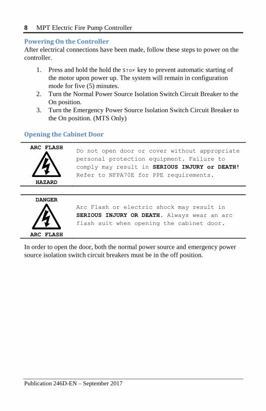
Powering On the Controller After electrical connections have been made, follow these steps to power on the
controller.
1. Press and hold the hold the S T O P key to prevent automatic starting of
the motor upon power up. The system will remain in configuration
mode for five (5) minutes.
2. Turn the Normal Power Source Isolation Switch Circuit Breaker to the
On position.
3. Turn the Emergency Power Source Isolation Switch Circuit Breaker to
the On position. (MTS Only)
Opening the Cabinet Door
ARC FLASH
HAZARD
Do not open door or cover without appropriate
personal protection equipment. Failure to
comply may result in SERIOUS INJURY or DEATH!
Refer to NFPA70E for PPE requirements.
DANGER
ARC FLASH
Arc Flash or electric shock may result in
SERIOUS INJURY OR DEATH. Always wear an arc
flash suit when opening the cabinet door.
In order to open the door, both the normal power source and emergency power
source isolation switch circuit breakers must be in the off position.
MPT Electric Fire Pump Controller 9
Publication 246D-EN – September 2017
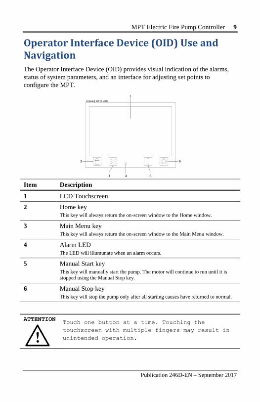
Operator Interface Device (OID) Use and Navigation The Operator Interface Device (OID) provides visual indication of the alarms,
status of system parameters, and an interface for adjusting set points to
configure the MPT.
Item Description
1 LCD Touchscreen
2 Home key
This key will always return the on-screen window to the Home window.
3 Main Menu key
This key will always return the on-screen window to the Main Menu window.
4 Alarm LED
The LED will illumunate when an alarm occurs.
5 Manual Start key
This key will manually start the pump. The motor will continue to run until it is stopped using the Manual Stop key.
6 Manual Stop key
This key will stop the pump only after all starting causes have returned to normal.
ATTENTION Touch one button at a time. Touching the
touchscreen with multiple fingers may result in
unintended operation.
1
Drawing not to scale
2
3 5
6
4
10 MPT Electric Fire Pump Controller
Publication 246D-EN – September 2017
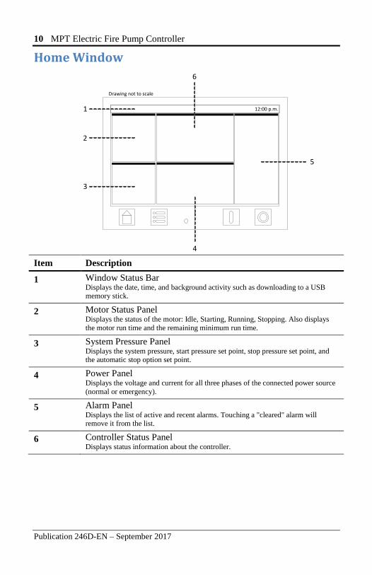
Home Window
Item Description
1 Window Status Bar Displays the date, time, and background activity such as downloading to a USB memory stick.
2 Motor Status Panel Displays the status of the motor: Idle, Starting, Running, Stopping. Also displays
the motor run time and the remaining minimum run time.
3 System Pressure Panel Displays the system pressure, start pressure set point, stop pressure set point, and the automatic stop option set point.
4 Power Panel Displays the voltage and current for all three phases of the connected power source
(normal or emergency).
5 Alarm Panel Displays the list of active and recent alarms. Touching a "cleared" alarm will remove it from the list.
6 Controller Status Panel Displays status information about the controller.
Drawing not to scale
2
3
4
5
6
1 12:00 p.m.
MPT Electric Fire Pump Controller 11
Publication 246D-EN – September 2017
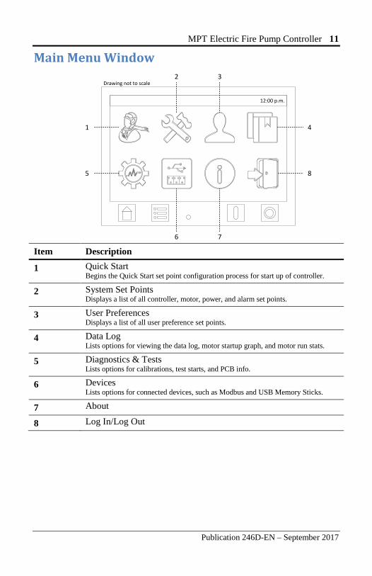
Main Menu Window
Item Description
1 Quick Start Begins the Quick Start set point configuration process for start up of controller.
2 System Set Points Displays a list of all controller, motor, power, and alarm set points.
3 User Preferences Displays a list of all user preference set points.
4 Data Log Lists options for viewing the data log, motor startup graph, and motor run stats.
5 Diagnostics & Tests Lists options for calibrations, test starts, and PCB info.
6 Devices Lists options for connected devices, such as Modbus and USB Memory Sticks.
7 About
8 Log In/Log Out
1
Drawing not to scale
5
2 3
4
8
6 7
12:00 p.m.
12 MPT Electric Fire Pump Controller
Publication 246D-EN – September 2017
User Log In
Navigating and viewing set point configurations is allowed at all times;
however, changing any set point configuration requires the user password. The
user password is shown below. This password is also on a label affixed to the
cabinet door on the inside.
When prompted for the user password, enter the following pin number:
1 2 3 3 3 3
Logging Out If there is no user activity on the OID after five minutes, the login state is
automatically logged out.
To manually log out:
From the Main Menu window, touch the Log Out button.
MPT Electric Fire Pump Controller 13
Publication 246D-EN – September 2017
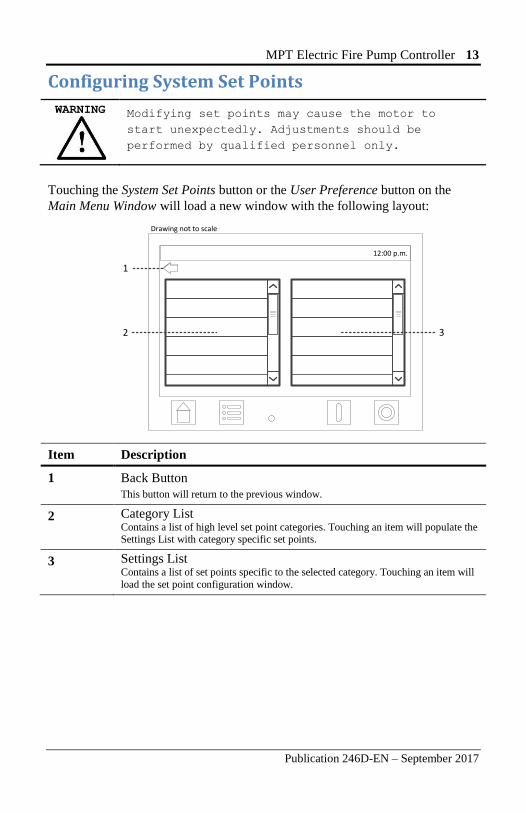
Configuring System Set Points
WARNING
Modifying set points may cause the motor to
start unexpectedly. Adjustments should be
performed by qualified personnel only.
Touching the System Set Points button or the User Preference button on the
Main Menu Window will load a new window with the following layout:
Item Description
1 Back Button
This button will return to the previous window.
2 Category List Contains a list of high level set point categories. Touching an item will populate the Settings List with category specific set points.
3 Settings List Contains a list of set points specific to the selected category. Touching an item will
load the set point configuration window.
Drawing not to scale
12:00 p.m.
1
2 3
14 MPT Electric Fire Pump Controller
Publication 246D-EN – September 2017
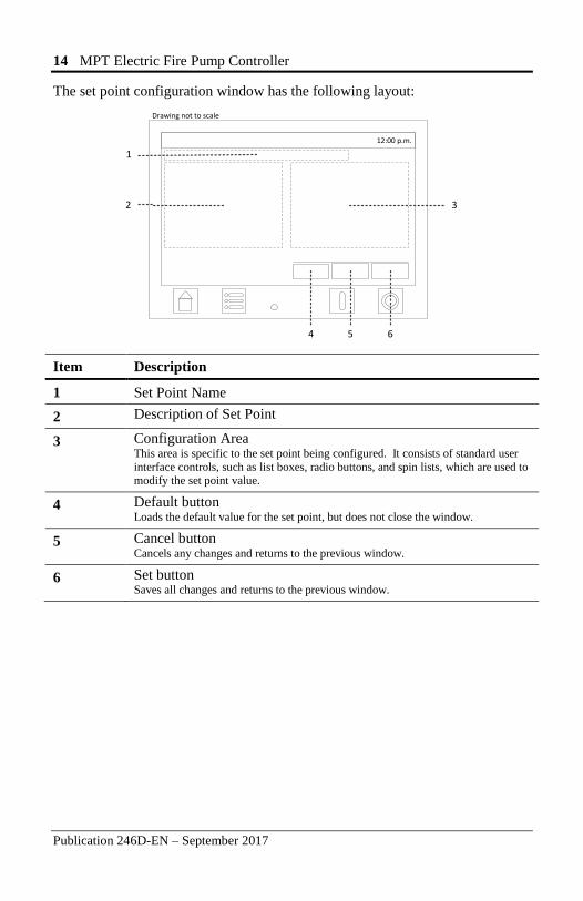
The set point configuration window has the following layout:
Item Description
1 Set Point Name
2 Description of Set Point
3 Configuration Area This area is specific to the set point being configured. It consists of standard user
interface controls, such as list boxes, radio buttons, and spin lists, which are used to modify the set point value.
4 Default button Loads the default value for the set point, but does not close the window.
5 Cancel button Cancels any changes and returns to the previous window.
6 Set button Saves all changes and returns to the previous window.
2
Drawing not to scale
4
3
5 6
12:00 p.m.
1
MPT Electric Fire Pump Controller 15
Publication 246D-EN – September 2017
Quick Start
The quick start feature is used to sequentially configure the primary system set
points without having the navigate through the onscreen menu. The following
set points are configured: Language, Pressure Unit, Date & Time, Start Pressure,
Stop Pressure, Start Delay, Automatic Stop, Min Run Time, and Auto Weekly Test Option. Refer to Main Menu Window, Item 1, on page 11 above.
To perform a quick start:
1. From the Main Menu window, touch Quick Start.
2. Configure each set point one at a time, pressing the Next button to
move to the next set point.
3. The window will return to the Main Menu after the last Quick Start set
point has been configured.
NOTE: Canceling the Quick Start process will discard all changes.
16 MPT Electric Fire Pump Controller
Publication 246D-EN – September 2017
Set Points List
System Set Point Window
Pressure Settings
Start Pressure
Stop Pressure
High Pressure Option
High Pressure Level
High Pressure Alarm Delay
Low Pressure Option
Low Pressure Level
Low Pressure Alarm Delay
Pressure Change Data Log
Event
Max Time Between Pressure
Event
Test Start Settings
Dump Valve Timeout
Shutdown on Alarm
Auto Weekly Test Option
Auto Weekly Test Day of Week
Auto Weekly Test Start Time
Auto Weekly Test Duration
Motor Start Settings
Start Delay
Pressure Sensor Failure Start
Deluge Valve Start
Restart Time Delay
Start Transition Time Delay
(MPT700)
Allow Start with Phase Loss
Remote Start Option
Remote Start Normal Contact
Supervisory Power Fail Start
Supervisory Power Fail Start
Delay
Motor Stop Settings
Auto Stop
Minimum Run Time
Low Intake Shutdown
Low Intake Trip Time
Low Intake Auto Reset
Low Intake Contact
Normal Power Settings
Phase Order
Low Voltage Trip Percent
Low Voltage Time Delay
High Voltage Trip Percent
High Voltage Time Delay
Phase Loss Time Delay
Under Frequency Percent
Under Frequncy Time Delay
Over Frequency Percent
Over Frequency Time Delay
Emergency Power Settings1
Low Voltage Trip Percent
Low Voltage Time Delay
High Voltage Trip Percent
High Voltage Time Delay
Phase Loss Time Delay
Under Frequency Percent
Under Frequncy Time Delay
Over Frequency Percent
Over Frequency Time Delay
Transfer Switch Settings1
Transfer to Emergency Delay
Retransfer Delay
Unloaded Run Time
Emergency Source Type
High Zone Settings
High Zone Option
Start Contact to Low Zone
Lockout Contact from Low
Zone
Start Delay
Always Start
Aux Programs
Aux Program 1–48
1 MTS Only for all set points under category
MPT Electric Fire Pump Controller 17
Publication 246D-EN – September 2017
User Preference Window
User Preferences
Language
GUI Theme
Pressure Unit
Temperature Unit
Date Format
Time Format
Idle Timeout
Change User Password
Date & Time
Set Date
Set Time
Set Timezone
Daylight Saving Time Option
DST Start Date
DST End Date
Screen Settings
Brightness
LCD Auto Dim
Calibrate Touch Screen
18 MPT Electric Fire Pump Controller
Publication 246D-EN – September 2017
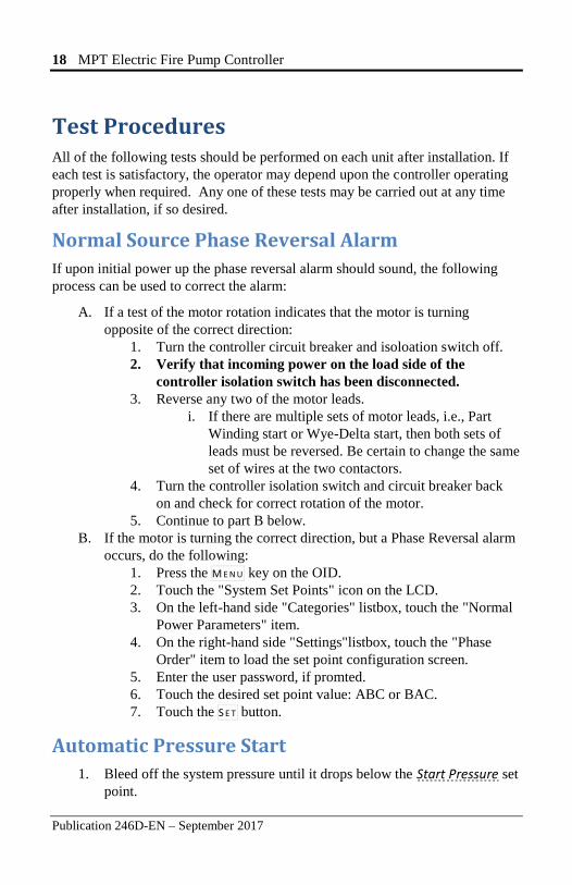
Test Procedures All of the following tests should be performed on each unit after installation. If
each test is satisfactory, the operator may depend upon the controller operating
properly when required. Any one of these tests may be carried out at any time
after installation, if so desired.
Normal Source Phase Reversal Alarm
If upon initial power up the phase reversal alarm should sound, the following
process can be used to correct the alarm:
A. If a test of the motor rotation indicates that the motor is turning
opposite of the correct direction:
1. Turn the controller circuit breaker and isoloation switch off.
2. Verify that incoming power on the load side of the
controller isolation switch has been disconnected.
3. Reverse any two of the motor leads.
i. If there are multiple sets of motor leads, i.e., Part
Winding start or Wye-Delta start, then both sets of
leads must be reversed. Be certain to change the same
set of wires at the two contactors.
4. Turn the controller isolation switch and circuit breaker back
on and check for correct rotation of the motor.
5. Continue to part B below.
B. If the motor is turning the correct direction, but a Phase Reversal alarm
occurs, do the following:
1. Press the M E N U key on the OID.
2. Touch the "System Set Points" icon on the LCD.
3. On the left-hand side "Categories" listbox, touch the "Normal
Power Parameters" item.
4. On the right-hand side "Settings"listbox, touch the "Phase
Order" item to load the set point configuration screen.
5. Enter the user password, if promted.
6. Touch the desired set point value: ABC or BAC.
7. Touch the S E T button.
Automatic Pressure Start
1. Bleed off the system pressure until it drops below the Start Pressure set
point.
MPT Electric Fire Pump Controller 19
Publication 246D-EN – September 2017
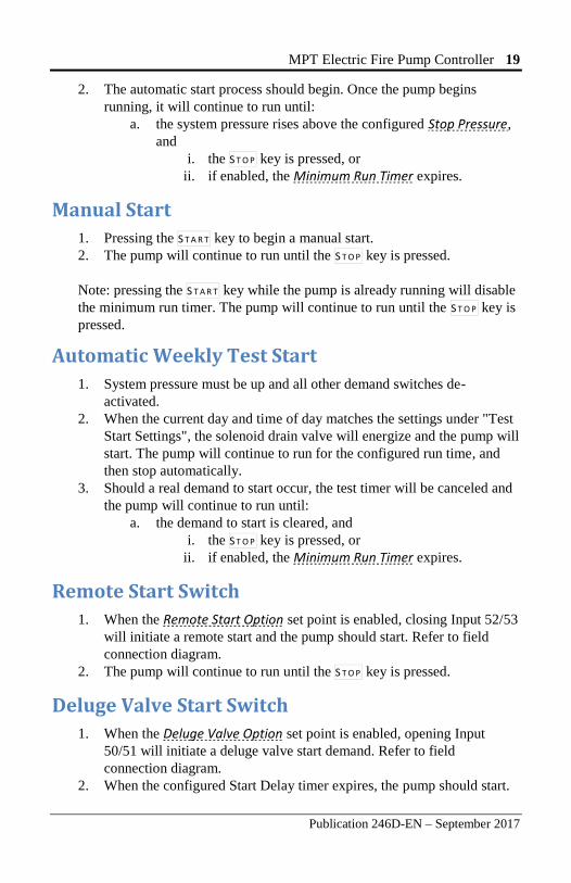
2. The automatic start process should begin. Once the pump begins
running, it will continue to run until:
a. the system pressure rises above the configured Stop Pressure,
and
i. the S T O P key is pressed, or
ii. if enabled, the Minimum Run Timer expires.
Manual Start
1. Pressing the S T A R T key to begin a manual start.
2. The pump will continue to run until the S T O P key is pressed.
Note: pressing the S T A R T key while the pump is already running will disable
the minimum run timer. The pump will continue to run until the S T O P key is
pressed.
Automatic Weekly Test Start
1. System pressure must be up and all other demand switches de-
activated.
2. When the current day and time of day matches the settings under "Test
Start Settings", the solenoid drain valve will energize and the pump will
start. The pump will continue to run for the configured run time, and
then stop automatically.
3. Should a real demand to start occur, the test timer will be canceled and
the pump will continue to run until:
a. the demand to start is cleared, and
i. the S T O P key is pressed, or
ii. if enabled, the Minimum Run Timer expires.
Remote Start Switch
1. When the Remote Start Option set point is enabled, closing Input 52/53
will initiate a remote start and the pump should start. Refer to field
connection diagram.
2. The pump will continue to run until the S T O P key is pressed.
Deluge Valve Start Switch
1. When the Deluge Valve Option set point is enabled, opening Input
50/51 will initiate a deluge valve start demand. Refer to field
connection diagram.
2. When the configured Start Delay timer expires, the pump should start.
20 MPT Electric Fire Pump Controller
Publication 246D-EN – September 2017
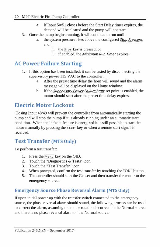
a. If Input 50/51 closes before the Start Delay timer expires, the
demand will be cleared and the pump will not start.
3. Once the pump begins running, it will continue to run until:
a. the system pressure rises above the configured Stop Pressure,
and
i. the S T O P key is pressed, or
i. if enabled, the Minimum Run Timer expires.
AC Power Failure Starting
1. If this option has been installed, it can be tested by disconnecting the
supervisory power 115 VAC to the controller.
a. After the preset time delay the horn will sound and the alarm
message will be displayed on the Home window.
b. If the Supervisory Power Failure Start set point is enabled, the
motor should start after the preset time delay expires.
Electric Motor Lockout
Closing Input 48/49 will prevent the controller from automatically starting the
pump and will stop the pump if it is already running under an automatic start
condition. When the lockout feature is energized it is still possible to start the
motor manually by pressing the S T A R T key or when a remote start signal is
received.
Test Transfer (MTS Only)
To perform a test transfer:
1. Press the M E N U key on the OID.
2. Touch the "Diagnostics & Tests" icon.
3. Touch the "Test Transfer" icon.
4. When prompted, confirm the test transfer by touching the "OK" button.
5. The controller should start the Genset and then transfer the motor to the
emergency source.
Emergency Source Phase Reversal Alarm (MTS Only)
If upon initial power up with the transfer switch connected to the emergency
source, the phase reversal alarm should sound, the following process can be used
to correct the alarm, assuming the motor rotation is correct on the Normal source
and there is no phase reversal alarm on the Normal source:
MPT Electric Fire Pump Controller 21
Publication 246D-EN – September 2017
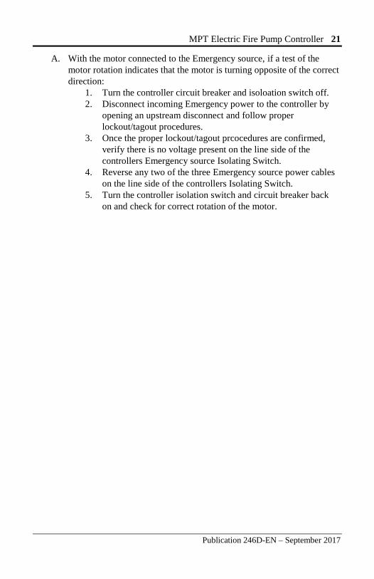
A. With the motor connected to the Emergency source, if a test of the
motor rotation indicates that the motor is turning opposite of the correct
direction:
1. Turn the controller circuit breaker and isoloation switch off.
2. Disconnect incoming Emergency power to the controller by
opening an upstream disconnect and follow proper
lockout/tagout procedures.
3. Once the proper lockout/tagout prcocedures are confirmed,
verify there is no voltage present on the line side of the
controllers Emergency source Isolating Switch.
4. Reverse any two of the three Emergency source power cables
on the line side of the controllers Isolating Switch.
5. Turn the controller isolation switch and circuit breaker back
on and check for correct rotation of the motor.
22 MPT Electric Fire Pump Controller
Publication 246D-EN – September 2017
Disposal Metron Eledyne is a member of a compliance scheme under the Waste Electrical
and Electronic Equipment regulations which is applicable in all EC countries. At
the end of the service life of the equipment the company offers to collect and
dispose of this equipment in accordance with regulations in force under the
Registration Number WEE/CF0105WV. (Equipment must be suitably packed
for collection by courier if outside the UK).
Contact:
Tel: +44 (0) 1476 516120
Fax: +44 (0) 1476 516121
MPT Electric Fire Pump Controller 23
www.metroninc.com www.metroneledyne.co.uk
Hubbell Industrial Controls, Inc. Metron Fire Pump Controls Division 4301 Cheyenne Drive, Archdale NC 27263 USA, Tel: (336) 434-2800, Fax: (336) 434-2803
Hubbell Limited incorporating Metron Eledyne, Stretton Business Park, Brunel Drive, Burton-on-Trent Staffordshire, DE13 0BZ, United Kingdom Tel: +44 (0) 1283 500 500, Fax: +44 (0) 1283 500 400
Publication 246D-EN – September 2017 Printed in USA
Replacement Parts For replacement parts, contact your local Metron sales office or the Metron
factory at:
United States Telephone: +1 (336) 434-2800 ext. 202
FAX: +1 (336) 434-2809
Email: [email protected]
Europe Telephone: +44 (0) 7730 050 100
Email: [email protected]
Technical Support
United States For 24-hour technical support:
Telephone: +1 (336) 434-2800 ext. 183
Email: [email protected]
Europe Service & Commissioning
Telephone: +44 (0) 1283 493 215
Email: [email protected]
Emergency Contact:
Telephone: +44 (0) 7730 050100


