Download - Modelling Of Automobile Brake Pad Wear

© OCT 2019 | IRE Journals | Volume 3 Issue 4 | ISSN: 2456-8880
IRE 1701714 ICONIC RESEARCH AND ENGINEERING JOURNALS 227
Modelling Of Automobile Brake Pad Wear
OGBEIDE S. O.1, PH.D ANWULE LIBERTY
2
1Ambrose Alli University, Faculty of Engineering and Engineering Technology, Department of
Mechanical Engineering, Ekpoma, Edo State, Nigeria 2College of Education, Agbor, Delta State, Nigeria
Abstract- In the optimization of wear resistance of
automotive brake pads, the braking temperature as
a result of contact surface of the disc and the pads
of a friction brake during its operation has
significant impact on brake performance. An
interaction between a brake disc and brake pads of
automobile brake is characterized by a number of
dry contact phenomena; these phenomena are
influenced by brake operation conditions (applied
pressure, speed and brake interface temperature)
and material characteristics of friction couple at a
given time. The temperature measurement
techniques, which are always available under
laboratory test conditions at different radial
distance enable obtaining relatively accurate values
of temperature at the friction surface using thermo
couples. However, measuring the sliding surface
temperature at different radial distance during the
entire lifetime of the brake pads is very necessary
due to the demanding operating conditions of the
brakes. Therefore, an appropriate mathematical
model was developed in order to enable estimate of
the sliding surface temperature between the brake
disc and brake pads throughout the entire duration
of brake application. This is achieve by infinite
element method using the results of the of
temperature measurement at different radial and
axial distance within the brake pad and its
processing, by means of an originally developed
mathematical model which aided the analysis of
results and validation of the mathematical model.
The finite element analysis is simplified by utilizing
the inherent symmetry of disc brake and applying
symmetric boundary conditions. The finite element
analysis results presented herein illustrate that the
brake pads temperature varies at different radial
distance. While making comparison of temperature
at different radial distance of the pad and disc ,the
maximum and minimum values and the difference
between them were: pad highest surface
temperature was 8800C and the lowest surface
temperature value was 700°C, the difference of
temperature was 130°C. Considering the wearing
rate in radial and axial distance when the rate of
wear rises most in radial direction, the temperature
occurring on the surface and the temperature
difference between two surfaces also rises. At a time
of 1.5 to 2.5 sec maximum heat was generated and
the temperature of pad and disc rises. Above 2.5
however, convection heat lost set in, this is as a
result of nature trying to obey Newton’s law of
cooling which reduced the temperature in the
interval 2.5 to 4 sec. Disc surface temperature in the
radial interval 75-85 mm, where the disc is exposed
to air flow is relatively low. But in the interval 85-
105 mm, where the disc is in contact with friction
linings, the temperature increased because in the
case of uniform pressure distribution, heat
generation grows in the radial distance. It was
finally observed that if the thickness of the pad is
reduced due to excessive wear, influence of heat
into the pad and caliper assembly increases and the
risk of brake fluid vaporization will increase leading
to brake temperature rise. Therefore, it was
recommended that the material with low thermal
conductivity for the pad and caliper components be
used and to build a test rig for real braking system
to study the heat dissipation experimentally so that
the analysis result obtained from finite element
method can be validated.
Indexed Terms- Modelling, Automobile, Brake Pad,
braking temperature, Wear
I. INTRODUCTION
The overall aim of this study is allow for prediction
of pad performance based on intrinsic external
influences such as temperature and heat dissipations
and assess its thermal performance in the early design
stage. The study would seek to fulfill the following
objectives; To determine the contact temperature

© OCT 2019 | IRE Journals | Volume 3 Issue 4 | ISSN: 2456-8880
IRE 1701714 ICONIC RESEARCH AND ENGINEERING JOURNALS 228
distribution on the working surface of a brake with
the aid of thermocouples. Develop mathematical
models for describing the thermal behavior of a disc
brake wear in a vehicle. Develop a time dependent
heat equation from energy balance for the brake rotor
and the pads.
The automobile industry is one of the most
economically vibrant industries in national
development. Development of durable, effective,
healthy and reduced cost brake pads is not only going
to satisfy environmental and safety requirements but
will contribute to national development. In this study,
analytical and finite element analysis approach will
be conducted in order to identify the temperature
distributions and behaviors of disc brake rotor in
transient response of automobile brake system will be
developed and some experiment will be carried out
on the brake pad materials to understand heat
mechanism with related variables and the
performance. To characterize the temperature fields
of the solid rotor with appropriate thermal boundary
conditions to ascertain the heat conduction in a disk
brake system in respect to time.
An automotive brake functions by converting the
vehicle’s kinetic energy into heat energy. During
braking, the heat energy is first born by the two
contact surfaces of the brake, namely the brake disc
and the brake pad (or drum and shoe in the case of
the drum brake), and is the transferred to the
contacting components brake such as calipers of the
brake, as well as the surroundings. According to a
research study by (Frost, N.& Sullivan F.2002), there
is likelihood that after 2010, the global automotive
industry will start using brake-by-wire systems
instead of hydraulic braking systems. The various
technologies such as electro mechanical braking
system and the electronic wedges brake are soon
going to replace the older braking systems. With the
help of these brake-by-wire systems, automobile
drivers will be having more control on their vehicles
particularly in case of sheer emergency. The braking
system used in automobiles is mainly used for
helping the driver control the deceleration of the
vehicle. It is one of the crucial systems, which is
especially designed for decreasing the speed of the
fast moving vehicle. Shahril,K., Monarita N., and
Aliff , S., 2012).
According to (Mr. Ajit B. Jain, Dr. S.G. Taji and
Prof. H.S. Bawiskar, 2008). For Better transportation
there is need for automobile manufacturers to provide
good safety systems. The brake system has become
important active safety systems. The disc brake is a
device for deaccelerating or stopping the rotation of a
wheel. This work presents the analysis of the contact
pressure at the disc interfaces using a detailed 3-
dimensional model of a brake in FEM. Finite element
(FE) model of the brake-disc is created using solid
modeling Software i.e. Pro-E and Analyzed in
ANSYS which is based on the finite element method
(FEM). It also investigates contact pressure
distributions at varying load. Due to rise in
temperature the change in angular velocity and the
contact pressure is also studied. Wear reduces the life
of friction material. Due High wear, the frictional
material needs to be replaced Continuously. Problems
such as Continuous wear of brake pads and thermal
cracks in brake discs are due to high temperatures.
Continuously controlling the temperature and thermal
and mechanical stresses are critical to proper
functioning of the braking system. Cooling of Brake
System is further an important aspect to consider for
brake disc durability and performance. Different
materials for brake pads is tested as compared with
the existing one. Finally comparison between
analytical results and result obtained from Analyses
is carried out and all the values obtained from the
analysis are less than their Permissible values. Hence
on the basis of thermal and contact stress analysis
best suitable material is suggested.
Nagy et al. (1994) pioneered the transient analysis of
disc brakes using the finite element method. The
nonlinearity of the friction at the rotor/pads contact
was considered. They found that the stability of the
system was mainly influenced by the friction
coupling the rotor and the pads. Hu and Nagy (1997)
developed the method of Nagy et al. (1994) and
tackled large finite element models of disc brakes.
Dynamic contact was considered by incorporating a
penalty function to model the contact surface in the
virtual work statement. Another merit of this work
was the use of pressure-dependent friction coefficient
obtained from dynamometer tests. To speed up the
explicit numerical integration and yet maintain
accuracy, they used a one-point-integration solid

© OCT 2019 | IRE Journals | Volume 3 Issue 4 | ISSN: 2456-8880
IRE 1701714 ICONIC RESEARCH AND ENGINEERING JOURNALS 229
element with stiffness hourglass control that they
developed with Belytschko. The numerical time-
domain information was converted to power spectral
density data through FFT. Several predicted
frequencies of high sound level compared well with
squeal frequencies found from experiments. Chargin
et al. (1997) also performed a transient analysis for a
simple finite element model of a brake. They used
implicit integration with tangent matrices of the
steady-state solution. This was the point to start the
complex eigenvalue analysis. Again, the contact
constraint was imposed by the Lagrange multiplier. A
stiff equation solver was necessary to solve the
resultant differential equations. Hu et al. (1999)
investigated the effects of friction characteristics and
structural modifications (such as pad chamfer or
slot). An optimal design was found using Taguchi
method. Mahajan et al. (1999) used the same method
of Nagy et al. (1994) and the procedure of Hu et al.
(1999) and compared the transient analysis, complex
eigenvalue analysis and normal mode analysis and
found that they were useful at different stages of
design. Following Nagy and Hu’s approach, Chern et
al. (2002) performed a nonlinear transient analysis of
a disc brake including rotor, pads, two pistons,
sliding pins, and anchor bracket using LS/DYNA
with constant dynamic friction coefficient’s the
squeal frequency and the corresponding operational
deflection shape of the rotor, respectively.
A moving vehicle possesses an amount of kinetic
energy depending on the weight and speed of the
vehicle. This energy must be dissipated in order for
the vehicle to slow down or stop. Brakes serve to
reduce the velocity of a vehicle in this scenario. The
focus of this project is on the mechanisms of braking,
primarily the physical interaction between the friction
components in a disc brake system. Braking torque
and contact forces of different brake pad materials
under a constant brake pressures are studied in order
to analyze this interaction. The goal of this project is
to allow for the prediction of pad performance based
on intrinsic material properties. While such an
approach does not completely study the external
influences or sophisticated details of wear and heat
dissipation, it will still provide a firm basis and
potential starting point for the study of brake pad
materials (Jared Feist, 2014).
Voller, et al.(2003) perform a Analysis of automotive
disc brake cooling characteristics. The aim of this
investigation was to study automotive disc brake
cooling characteristics experimentally using a
specially developed spin rig and numerically using
finite element (FE) and computational fluid dynamics
(CFD) methods. All three modes of heat transfer
(conduction, convection and radiation) have been
analyzed along with the design features of the brake
assembly and their interfaces. The influence of brake
cooling parameters on the disc temperature has been
investigated by FE modelling of a long drag brake
application. The thermal power dissipated during the
drag brake application has been analysed to reveal
the contribution of each mode of heat transfer.
Zaid, et al. (2009) presented a paper on an
investigation of disc brake rotor by Finite element
analysis. In this paper, the author has conducted a
study on ventilated disc brake rotor of normal
passenger vehicle with full load of capacity . The
study is more likely concern of heat and temperature
distribution on disc brake rotor. In this study, finite
element analysis approached has been conducted in
order to identify the temperature distributions and
behaviors of disc brake rotor in transient response.
ABAQUS/CAE has been used as finite elements
software to perform the thermal analysis on transient
response. Thus, this study provide better
understanding on the thermal characteristic of disc
brake rotor and assist the automotive industry in
developing optimum and effective disc brake rotor.
In a study, where the heat conduction problems of the
disk brake components (pad and rotor) are modeled
mathematically and was solved numerically using
Finite Difference Method. In the discretization of
time dependant equations the implicit method is
taken into account. In the derivation of the heat
equations, parameters such as the duration of braking,
vehicle velocity, geometries and the dimensions of
the brake components, materials of the disk brake
rotor and the pad and contact pressure distribution
have been taken into account. Results show that there
is a heat partition at the contact surface of two sliding
components, because of thermal resistance due to the
accumulation of wear particles between contact
surfaces. This phenomenon prevents absorption of
more heat by the discs and causes brake lining to be

© OCT 2019 | IRE Journals | Volume 3 Issue 4 | ISSN: 2456-8880
IRE 1701714 ICONIC RESEARCH AND ENGINEERING JOURNALS 230
hot. As a result, heat soaking to the brake fluid
increases and may cause brake fluid to evaporate
(Mazidi, S.Jalalifar, S. And Chakhoo, J. 2010).
Recently, disk brakes have been widely used in light
vehicles (Faramarz, T.,Salman J. 2009). Proper
performance of a vehicle brake system is one of its
advantages. Long repetitive braking leads to
temperature rise of various brake components of the
vehicle that reduces the performance of the brake
system. Long repetitive braking, such as one which
occurs during a mountain descent, will result in a
brake fluid temperature rise and may cause brake
fluid vaporization. This may be a concern particularly
for passenger cars equipped with aluminum calipers
and with a limited air flow to the wheel brake
systems. Braking performance of a vehicle can be
significantly affected by the temperature rise in the
brake components. High temperature during braking
may cause brake fade, premature wear, brake fluid
vaporization, bearing failure, thermal cracks, and
thermally excited vibration. Therefore, it is important
to predict the temperature rise of a given brake
system and assess its thermal performance in the
early design stage. Recently, brake fluid vaporization
has been suspected as a possible cause of some
collisions and a proper inspection procedure has been
recommended.
Currently, brake pads in automobiles are made of
composite materials composed of more than ten
different ingredients. Sometimes, up to 20 or 25
different constituents are used. These ingredients are
categorized into four broad classes: binders,
structural materials, fillers and frictional
additives/modifiers (Mohanty, and Chugh, 2007).
The binders bind together rest of the ingredients,
structural materials provide the structural
reinforcement to the composite matrix, fillers make
up the volume of the brake lining, while keeping the
cost down, and friction modifiers stabilize the
coefficient of friction (Eriksson and Jacobson, 2000).
Investigations into the effect of different ingredients
on brake performance are available in literatures (
Hee K W, Filip, 2005, Cho et al., 2005, Cho et al.,
2006, Gudmand- Hoyer and Bach, 1999, Bijwe et al.,
2005, Jang et al., 2000, Kim and Jang, 200, Jang et
al., 2001, Jang et al., 2003).
A mathematical model to describe the thermal
behavior of a brake system ( Naji et al,2002) was
presented which consists of the shoe and the drum.
The model was solved analytically using Green’s
function method for any type of the stopping braking
action. The thermal behavior is investigated for three
specified braking actions which were the impulse, the
unit step and trigonometric stopping action.
An analytical model presented by (Gao and Lin,
2002) for the determination of the contact
temperature distribution on the working surface of a
brake. To consider the effects of the moving heat
source (the pad) with relative sliding speed variation,
a transient finite element technique is used to
characterize the temperature fields of the solid rotor
with appropriate thermal boundary conditions.
Numerical results shows that the operating
characteristics of the brake exert an essentially
influence on the surface temperature distribution and
the maximal contact temperature.
In a study by (Talati and Jalalifar, 2008), two major
models are used for calculation of frictional heat
generation: namely macroscopic and microscopic
model. In the macroscopic model, the law of
conservation of energy or first law of
thermodynamics is taken into account. And for the
microscopic model, parameters such as the duration
of braking, velocity of the vehicle, dimensions and
geometry of the braking system, material of the disk
brake rotor and the pad are taken into account. For
calculation of prescribed heat flux boundary
condition in their model, two kinds of pressure
distribution are considered: uniform wear and
uniform pressure.
II. MATERIALS
Brake disc are traditionally made from grey cast iron
due to its strength and durability, stable mechanical
and frictional properties, wear resistance, heat
absorption, thermal conductivity, vibration damping
capacity and low cost. While brake pads are typically
a manufacturer proprietary composite of different
friction materials based on the desired performance.
Brake pads material blends are categorized as
metallic, semi-metallic, organic, or carbon/ceramic
depending upon the material composition. The Finite

© OCT 2019 | IRE Journals | Volume 3 Issue 4 | ISSN: 2456-8880
IRE 1701714 ICONIC RESEARCH AND ENGINEERING JOURNALS 231
Element Analysis (FEA) applied elastic material
properties of Society of Automotive Engineer (SAE)
SAE J430 G10H19 grey cast iron for the disc. The
brake pad material compositions are varied
throughout this project to investigate the variation in
braking performance. The material properties used in
the FEA for each component are summarized in
Table 1.
Table 1: The material properties used in the FEA
Friction
component
Mass
Density
(Kg/m3)
Elastic
Modulus
(Gpa)
Poission
Ratio
Disc (Steel) 7150 140 0.24
Pad
(Ceramic Al
204)
3800 325 0.22
A mathematical model is use for the determination of
the contact temperature distribution on the working
surface of the brake. First to consider the effects of
the moving heat source (the pad) with relative sliding
speed variation, a transient finite element technique is
used to characterize the temperature fields of the
solid rotor with appropriate thermal boundary
conditions.
For calculation of heat generation due to friction, rate
of dissipated heat via friction should be taken into
account. This is all to do with the calculation of
friction force and rate of work done by friction force.
III. METHODOLOGY
As previously stated, temperature measurement in the
friction surfaces of a brake is a difficult task. This is
due to numerous influencing factors specific to
rubbing surfaces such as those in friction brakes,
especially since it is necessary to provide temperature
measurement with an appropriate accuracy and
minimum delay. When comparing all the available
techniques of temperature measurement, the method
using thermocouples shows significant advantages
over others; they are very effective for measuring the
temperature in the contact of the friction pair. In this
case, a so-called “hot end” or hot junction is located
very close to the friction surface. However, it must be
taken into consideration that the thermocouple should
not at any time be exposed to direct rubbing over the
friction surface in order to eliminate the potential
impact on the quality of the measuring signal of the
thermocouple sliding itself over the metal surface as
much as possible. This kind of problems may be
avoided if the thermocouple is positioned within the
pad, very close to the sliding surface, e.g. 0.5 mm
deep from it (SAE J843). In the present study, one
temperature sensor was located in such a position,
and it will be used to measure the temperature on the
friction surface (T1). However, given the requirement
that the temperature at the friction surface be
measured throughout the lifespan of brake pads, this
position is not satisfactory due to wearing
phenomena.
Therefore, another thermocouple (T2) will be
positioned 12.5 mm deep from the contact surface,
within the pad. The position of this thermocouple is
close to the backing plate, and it is defined by the
thickness of the brake lining material. This
thermocouple is not exposed to the effects of
wearing, which ensures its use throughout the
operating period. It is important to note that both
thermocouples were placed at the friction radius of
the pad. The measurement was carried out at the
Kaduna automobile brake system laboratory, with a
car disc brake tested at a single-ended full-scale
inertia dynamometer. Temperature measurements
were carried out repeated with full-stop brake
applications over a total time of 600 seconds, with an
initial brake speed corresponding to linear vehicle
speed of 60 km/h, and with the control line pressure
of 60 bar, while the initial brake temperature at the
beginning of the measurement cycle was 100 ºC (±3
ºC). The brake was subject to cooling by means of
the fan operating throughout the measurement period.
In each brake application, a brake disc was first
accelerated until it reached the predetermined initial
brake speed, and consequently braked to a full stop.
After completing a single brake application, the brake
disc remained at a standstill.
IV. FINITE ELEMENT MODEL
The finite element method is a tool to get the
numerical solution of wide range of engineering
problem. The method is capable to handle any
complex shape or geometry, for any material under

© OCT 2019 | IRE Journals | Volume 3 Issue 4 | ISSN: 2456-8880
IRE 1701714 ICONIC RESEARCH AND ENGINEERING JOURNALS 232
different boundary and loading conditions. The
analysis requirement of engineering problems is
overcome with help of finite element method. The
difference between the analytical solution and finite
difference method is that the solution is obtained only
at discrete points. Therefore, dividing the region into
small regions and assigning each region a reference
index will be provide very accurate results. Solving
the circular boundary problem solved using the finite
difference approach defined in polar co-ordinates
(r,θ) is more convenient than using cartesian co-
ordinates as it avoids the use of awkward
differentiation formulae near the curved boundary.
Defining the mesh in the r-θ plane by the points of
intersection of the circles r=r1 + i*h, where i=0, 1, 2,
3 ..., r1 is the inner radius of the disc and h=(r2-
r1)/M, M is the number of
circles defined for the mesh and the straight lines θ= j
* l where j=0, 1, 2, 3.... and l=(θ2-θ1)/N , where N is
the number of divisions. These lines and circles are
called grid lines and their intersections are referred to
as mesh points of the grid or nodal points. The
distance between two nodal points is the grid sizes.
The developed finite element analysis model contains
a total of 278 elements and 597 degrees of freedom,
while the time step used during the numerical
computation was 0.01sec. The initial temperature
used during the simulation was set as 20ºC. Table
3.1 and 3.2 shows how the temperature increases
further from the centre of the disk rotor to the point
of the maximum temperature within the contact area
between the disk and the pad, and then it decreases.
There are two methods to solve finite element
problems, implicit and explicit. The implicit method
requires solving for a static or quasi-steady state
processes, while the explicit method uses an explicit
direct-integration procedure to solve dynamic
response problems. The finite element code used to
analyzed the disc and pad brake system herein
utilizes ABCQUS/Explicit, Abaqus 6.12 –EF3 to
solve a dynamic simulation of brake pad to disc
contact.
The assumption detailed to this point significantly
simplify the numerical analysis. However, a disc
brake has fairly symmetric configuration about Z-
axis as shown in Figure 2. The final finite element
model (FEM) assembly developed for this study is
thus 3D axisymmetric representation of disc brake.
The FEM geometry has half of the disc thickness,
and engages the disc on one surface with one pad,
utilizing a symmetric boundary condition about the
Z-axis.
Figure 2 – End View of Disc Brake Highlighting the
Symmetry
V. FINITE ELEMENT FORMULATION FOR
HEAT CONDUCTION
The unsteady heat conduction equation of each body
for an axisymmetric problem described in the
cylindrical coordinate system is given as follows;
𝜚𝑐𝜕𝑇
𝜕𝑡 =
1
𝑟 ∂∂r 𝑟𝑘𝑟
𝜕𝑇
𝜕𝑡 +
𝜕
𝜕𝑧 𝑘𝑧
𝜕𝑇
𝜕𝑧 (1)
With the boundary conditions and initial condition
T= T* on T0, (2)
qn=h(T-T∞) on T1 (3)
qn=q*n onT2(4)
T=T0attime=0(5)
Where,
Q, c. Kr and kz are the density, specific heat and
thermal conductivities in r and z direction of the
material respectively.
T* is the prescribed temperature
h is the heat transfer coefficient

© OCT 2019 | IRE Journals | Volume 3 Issue 4 | ISSN: 2456-8880
IRE 1701714 ICONIC RESEARCH AND ENGINEERING JOURNALS 233
q*n is the heat flux at each contact interface caused
by friction
T∞ is the ambient temperature
T0 is the initial temperature
ṭ0 , ṭ1 and ṭ2 are the boundaries on which temperature,
convection and heat flux are imposed.
A finite element formulation of unsteady heat
equation can be written in the following matrix form
as;
CTṪ + KHTT = R, (6 )
Where CT is the capacity matrix
KHT is the conductivity matrix
T and R are the nodal temperature and heat source
vector
The above equation is solved with the direct
integration method based on the assumption that the
temperature Tt at time t and the temperature Tt + Δt
at time t + ΔT have the following relation:
Tt + Δt = Tt +[ (1 – β) Ṫt + βṪt + Δt ] Δt. ( 7 )
Equation above can be used to reduce the ordinary
differential equation of equ. (7) to the following
implicit algebraic equation:
( CT + b1 KHT ) Tt+ Δt = ( CT – b2 KHT ) Tt+ b2Rt +
b1Rt + Δt , (8)
Where the variable b1and b2are given by
b1= β Δt, b2 = (1- β) Δt (9)
For different values of β, a well-known numerical
integration scheme can be obtained.
β ranges from 0.5 <β < 1.0
Bearing all this in mind, the model for the brake
contact surface temperature estimation was
developed in the following general form based on
polynomial regression:
TE(t) = T2 (t).k + dt2/dt .t.kv + d2T2 / dt
2.t
2/2 .ka. (10)
Where TE is the estimated brake interface
temperature, T2 the temperature measured within the
pad, t the time, k the temperature ratio, and kv, and
ka are coefficients representing speed and
acceleration of temperature increase intensity, i.e.
representing the coefficients of heat transfer through
the friction material. These coefficients also depend
on the composition of the brake pad friction material,
wear status, brake geometry and operating
conditions, as well as the position of thermocouple T2
in the depth of the friction material. The coefficient
of the speed of temperature increase intensity kv is
determined by fitting the estimated temperature TE to
the measured temperature T1. This process is
performed in the sequence of monotonous
temperature change in order to avoid the influence of
coefficient ka from Eq. (2). Because the estimated
temperature TE change does not fully correlate to that
of the temperature T1, neither by value nor by shape,
the value of the coefficient kv was calculated with a
simple linear regression method based on the least
squares criterion using measurement data of T1 and
T2 temperatures. Now, the coefficient ka remains the
only unknown parameter in Eq. (2). The least squares
criterion will give best value for parameter ka for the
process model using the polynomial regression
method and between the measured temperatures T1
and T2. After this procedure, the estimated
temperature TE could be calculated. The thus
obtained estimated (i.e. calculated) brake contact
surface temperature TE is presented and it can be seen
that estimated temperature TE follows both the shape
and the character of the behaviour of measured
temperature T1 very well, which seems to deviate
from the actual value by not more than ± 3 ºC. This
deviation can be assumed to come from the noise of
the measurement signal, being the result of
conditions by which measurement was carried out,
and a high sampling rate selected, even though it is a
relatively slow process.
VI. PART GEOMETRY AND MESH
The brake FEM uses a simplified version of a typical
domestic passenger vehicle’s disc brake system.
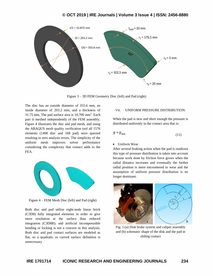
Figure 3 shows a simplified 3D solid disc, which
allows the model to use coarser meshes than would
be normally required to model the details of a typical
brake disc, given its complicated geosmetrical
features such as cooling ducts and bolt holes. Figure
3 also shows simplified 3D pad geometry and is
modeled such that it can only contact part of the
friction surface of the disc.
© OCT 2019 | IRE Journals | Volume 3 Issue 4 | ISSN: 2456-8880
IRE 1701714 ICONIC RESEARCH AND ENGINEERING JOURNALS 234
Figure 3 – 3D FEM Geometry Disc (left) and Pad (right)
The disc has an outside diameter of 355.6 mm, an
inside diameter of 203.2 mm, and a thickness of
31.75 mm. The pad surface area is 10,700 mm2. Each
part is meshed independently of the FEM assembly.
Figure 4 illustrates the disc and pad mesh, and using
the ABAQUS mesh quality verification tool all 1576
elements (1408 disc and 168 pad) were queried
resulting in zero analysis errors. The simplicity of the
uniform mesh improves solver performance
considering the complexity that contact adds to the
FEA.
Figure 4 – FEM Mesh Disc (left) and Pad (right)
Both disc and pad utilize eight-node linear brick
(C3D8) fully integrated elements in order to give
more resolution at the surface than reduced
integration (C3D8R); and artificial incompressible
bending or locking is not a concern in this analysis.
Both disc and pad contact surfaces are modeled as
flat, so a quadratic or curved surface definition is
unnecessary
VII. UNIFORM PRESSURE DISTRIBUTION:
When the pad is new and short enough the pressure is
distributed uniformly in the contact area that is:
(11)
Uniform Wear
After several braking action when the pad is rundown
this type of pressure distribution is taken into account
because work done by friction force grows when the
radial distance increases and eventually the farther
radial position is more encountered to wear and the
assumption of uniform pressure distribution is no
longer dominant.
Fig. 1:(a) Disk brake system and caliper assembly
and (b) schematic shape of the disk and the pad in
sliding contact

© OCT 2019 | IRE Journals | Volume 3 Issue 4 | ISSN: 2456-8880
IRE 1701714 ICONIC RESEARCH AND ENGINEERING JOURNALS 235
In this situation pressure distribution in the pad is
proportional to 1/r and maximum pressure occurs at r
= r2.
(12)
Where, δ is wear, pmax is the maximum pressure
distributed in the pad and p is the pressure at radial
position r.
VIII. HEAT GENERATION DUE TO FRICTION
In the contact area of brake components; the pads and
the disk; heat is generated due to friction. For
calculation of heat generation at the interface of these
two sliding bodies’ two methods is suggested:
At the basis of law of conservation of energy the
kinetic energy of the vehicle during motion is
equal to the dissipated heat after vehicle stop
By knowing the friction coefficient, pressure
distribution at the contact area, geometric
characteristics of the pad and the disk, relative
sliding velocity and duration of braking action
one can calculate the heat generated due to
friction
IX. HEAT EQUATION
Contact surface element of the disk and the pad is
shown in Fig. 2a and b, respectively. The rate of heat
generated due to friction between these surfaces is
calculated as follows:
(12a)
(12b)
(12c)
(12d)
where, is the rate of heat generated due to friction
between two sliding components, V is the relative
sliding velocity and dFf is the friction force. The
terms and are the amount of absorbed heat
by the pad and the disk, respectively. The parameter
σ is defined as:
(13)
where, ξp and ξd are the thermal effusivities of the
pad and the disk and Sp and Sd are frictional contact
surfaces of the pad and the disk, respectively.
Thermal effusivity is defined as:
(14)
Heat flux: To obtain the heat flux at the surfaces of
two components of the brake system, we divide rate
of thermal energy by the surface contact area of each
component.
Heat flux in the pad
(15)
Fig. 2:Contact surface element of two components (a)
the disk and (b) the pad
Heat flux in the disk
(16)
Heat flux for uniform pressure is a function of time
and space variable r; the angular velocity decreases
with time during braking action and the work done by
friction force grows as radial space variable
increases. Heat flux obtained for the uniform wear is
just a function of time and it is independent of the
space variable; the work done by friction force is the
same at radial direction.

© OCT 2019 | IRE Journals | Volume 3 Issue 4 | ISSN: 2456-8880
IRE 1701714 ICONIC RESEARCH AND ENGINEERING JOURNALS 236
X. HEAT EQUATION FOR THE PAD
Figure 3shows the two dimensional thermal problem
of the pad for two assumption of pressure
distribution; uniform wear and uniform pressure in
Fig. 3a and b, respectively. Heat equation and the
appropriate boundary conditions for the pad may be
written in the following form:
(16a)
(16b)
(16c)
(16d)
(16e)
(16f)
Discretization of heat conduction problem of the
pad
Figure 4 shows meshing of the finite difference
method of the pad. For discretization of the equations
the variables r, z and t are defined as:
(16g)
Fig. 3:Boundary conditions for the pad (a) uniform
wear and (b) uniform pressure
Fig. 4:Finite difference discretization of the pad
(16h)
(16i)
Energy absorbed by the brake
Energy absorbed by a brake depends on the type of
motion either pure translation or pure rotation or
combination of both.
When it is pure translation;
E1 = 1
2 M {(V1)
2 – (V2)
2 } (17a)
At a stop,
E1 = 1
2 M {(V1)
2 (17b)
When pure rotation;
E2 = 1
2 I { (Ѡ1)
2 –( Ѡ2)
2} (17c)
At a stop,
E2 = 1
2 I { (Ѡ1)
2 (17d)
XI. RESULTS AND DISCUSSION
From Table 3.1, the pad highest surface temperature
value is 780°C and the lowest surface temperature
value is 500°C, the difference of temperature is
280°C. The reason for this is that the thermal
conductivity parameter is low and specific heat value
is not high. Taking the wearing rate into account, the
surface temperature of the axial position from Table
3.2 the pad highest surface temperature is 8800C
tand the lowest surface temperature value is 700°C,
the difference of temperature is 130°C. Considering
the wearing rate in radial and axial distance when the
rate of wear rises most in radial direction, the
temperature occurring on the surface and the
temperature difference between two surfaces also
rises. In other radial distance as well, with the
increase of wear rate, the temperature value occurring
on the pad surface and the temperature difference
between two surfaces rises as well.
Table 3.1 Temperature of Pad and Disc at different
time (uniform wear)
Max Disc
Temp
Max Pad
Temp
Time (sec)
100 500 0.5
180 730 1.0
190 770 1.5
200 780 2.0
200 760 2.5
205 730 3.0
205 700 3.5
205 700 4.0
© OCT 2019 | IRE Journals | Volume 3 Issue 4 | ISSN: 2456-8880
IRE 1701714 ICONIC RESEARCH AND ENGINEERING JOURNALS 237
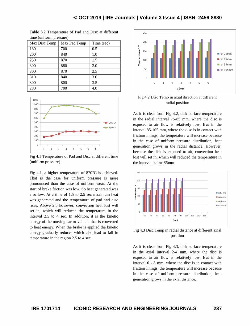
Table 3.2 Temperature of Pad and Disc at different
time (uniform pressure)
Max Disc Temp Max Pad Temp Time (sec)
180 700 0.5
200 840 1.0
250 870 1.5
300 880 2.0
300 870 2.5
310 840 3.0
300 800 3.5
280 700 4.0
Fig 4.1 Temperature of Pad and Disc at different time
(uniform pressure)
Fig 4.1, a higher temperature of 870°C is achieved.
That is the case for uniform pressure is more
pronounced than the case of uniform wear. At the
start of brake friction was low. So heat generated was
also low. At a time of 1.5 to 2.5 sec maximum heat
was generated and the temperature of pad and disc
rises. Above 2.5 however, convection heat lost will
set in, which will reduced the temperature in the
interval 2.5 to 4 sec. In addition, it is the kinetic
energy of the moving car or vehicle that is converted
to heat energy. When the brake is applied the kinetic
energy gradually reduces which also lead to fall in
temperature in the region 2.5 to 4 sec
Fig 4.2 Disc Temp in axial direction at different
radial position
As it is clear from Fig 4.2, disk surface temperature
in the radial interval 75-85 mm, where the disc is
exposed to air flow is relatively low. But in the
interval 85-105 mm, where the disc is in contact with
friction linings, the temperature will increase because
in the case of uniform pressure distribution, heat
generation grows in the radial distance. However,
because the disk is exposed to air, convection heat
lost will set in, which will reduced the temperature in
the interval below 85mm
Fig 4.3 Disc Temp in radial distance at different axial
position
As it is clear from Fig 4.3, disk surface temperature
in the axial interval 2-4 mm, where the disc is
exposed to air flow is relatively low. But in the
interval 6 - 8 mm, where the disc is in contact with
friction linings, the temperature will increase because
in the case of uniform pressure distribution, heat
generation grows in the axial distance.

© OCT 2019 | IRE Journals | Volume 3 Issue 4 | ISSN: 2456-8880
IRE 1701714 ICONIC RESEARCH AND ENGINEERING JOURNALS 238
XII. CONCLUSIONS AND
RECOMMENDATION
Results for contact surface temperature of the pad
and the disc show that there is a heat partition at the
contact surface of two sliding components. This is
because of thermal resistance due to the accumulation
of wear particles between contact surfaces of the pad
and the disc and lack of necessary provisions to
convection heat loss through the disk to the
surrounding.
Contact thermal resistance at the surfaces of the pad
and the disk prevent absorption of more heat by the
discs and causes brake lining to be hot. As a result,
heat soaking to the brake fluid increases and may
cause brake fluid to evaporate. So, the brake fluid
regarding to minimum wet and dry boiling point with
appropriate DOT ratings should be used.
As you know, caliper assembly is located at the end
of the pad. If the pad becomes too hot, it may
increase the temperature of the brake fluid and causes
evaporation. Therefore, it is recommended that the
material with low thermal conductivity for the pad
and caliper components is used.
If the thickness of the pad is reduced due to excessive
wear, influence of heat into the pad and caliper
assembly increases and the risk of brake fluid
vaporization will increase.
In this study, the temperature distributions and stress
situations of the pad materials during 2s occurring as
a result of permanently braking were examined using
finite element method. In the study, in order to
consider the impact of pad’s wear, the pad
thicknesses were examined as well.
In this paper, the governing heat equations for the
disk and the pad are extracted in the form of transient
heat equations with heat generation that is dependant
to time and space. In the derivation of the heat
equations, parameters such as the duration of braking,
vehicle velocity, geometries and the dimensions of
the brake components, materials of the disk brake
rotor and the pad and contact pressure distribution
have been taken into account. The problem is solved
analytically using Green’s function approach. It is
concluded that the heat generated due to friction
between the disk and the pad should be ideally
dissipated to the environment to avoid decreasing the
friction coefficient between the disk and the pad and
to avoid the temperature rise of various brake
components and brake fluid vaporization due to
excessive heating.
It is recommended building a test rig for real braking
system to study the heat dissipation experimentally so
that the analysis result obtained from finite element
software package can be validated. This small step
towards the development of a more thermally stable
brake system will give design engineers a hands on
quick on the go option during the initial stages of
prototype designing for the dimension and material
selection which could be further modified during the
later stages of product development.
REFERENCES
[1] Herbert Frood (1897), Investigation of cotton-
based Material Impregnated with Butimen
Solutions.
[2] Talati, F. and Jalalifar, S. (2008). Investigation of
Heat Transfer Phenoomena in a ventilated disk
brake rotor with straight radial rounded vanes.
Journal of Applied Science, Vol. 8, No. 20, P
3583-3590.
[3] Boz, M. and Kurt, A. (2007). The Effect of
AL2O3 on the Friction Performance of
Automotive Brake Friction Materials. J. Tribo.
Int., 40 : 1161 -11169.
[4] Jared Feist, (2014). Finite Element Modeling of
Brake Pad Materials Performance. Rensselaer
Polytechnic Institute Harford, Connecticut.
[5] SAE International J430, Surface Vehicle Standard
(2000). Automotive Gray Iron Casting.
[6] Gao and Lin (2002). The Determination of the
contact temperature distribution on the working
surface of a brake.
[7] Naji et al, (2002). Mathematical Model to
describe the thermal behaviour of a brake system.
© OCT 2019 | IRE Journals | Volume 3 Issue 4 | ISSN: 2456-8880
IRE 1701714 ICONIC RESEARCH AND ENGINEERING JOURNALS 239
[8] Cho et al ( 2003). Performance of a brake system
depends on the interaction of rotor with frction
materials at their sliding interfaces.
[9] Eriksson and Bergman (2000). Investigations into
the effect of different ingredients on brake pad
performance.
[10] Cheonan Daero et al (2015).Analyses of Structure
and Heat Transfer for Brake Pad and Shoe
Models .Advanced Science and Technology
Letters Vol.108 (Mechanical Engineering 2015),
pp.19-23
http://dx.doi.org/10.14257/astl.2015.108.05
[11] Huajiang Ouyang (2005). Numerical Analysis of
Automotive Disc Brake Squeal, Int. J. Vehicle
Noise and Vibration, Vol. 1, Nos. 3/4, 2005 207.
Fax: 0044 151 79 44848 E-mail:
[12] Er. N. B. Shinde1et al (2015). C.A.D. & F.E.M.
Analysis of Disc Brake System, International
Journal Of Engineering And Computer Science
ISSN:2319-7242 Volume 4 Issue 3 March
2015, Page No. 10697-10706.
[13] Shahril K.et al (2012). Temperature Analysis of
Automotive Modeling Parts. International
Conference on Metallurgical, Manufacturing and
Mechanical Engineering (ICMMME'2012)
December 26-27, 2012 Dubai (UAE)
[14] Eltoukhy, M.; Asfour, S.; Almakky, M. & Huang,
C. (2006). Thermoelastic Instability in Disk
Brakes: Simulation of the Heat Generation
Problem, Proceedings of the COMSOL Users
Conference,
[15] Boston Inoue, H. (1986). Analysis of brake judder
caused by thermal deformation of brake discs,
SAE Technical Paper Series, no. 865131.
[16] Jacobsson, H. (2003). Aspects of Disc Brake
Judder, Proceedings of the Institution of
Mechanical Engineers, Journal of Automobile
Engineering, 217, 419-430
[17] Jang, J.Y. & Khonsari, M.M. (2003). A
generalized thermoelastic instability analysis,
Proceedings of the royal society, A459, 309-329.
[18] Abdelahamid, M. K. (1997). Brake judder
analysis: Case studies, SAE, Technical Paper
Series, no. 972027.
[19] Anderson, E., et al. (1990). Hot spotting in
automotive friction systems, Wear, v. 135, pp.
319–337.
[20] Barber, J.R. (1967). The influence of thermal
expansion on the friction and wear process, Wear,
10, 155–159.
[21] Faramarz Talati and Salman Jalalifar (2009).
Analysis of heat conduction in a disk brake
system.Heat Mass Transfer (2009) 45:1047–1059
DOI 10.1007/00231-009-0476-y.
[22] Tianku Fu, (2000).Modeling and Performance
Analysis of ABS Systems with Nonlinear
Control. A Thesis in The Department of
Mechanical Engineering, Concordia University
Montreal, Quebec, Canada.
[23] Anurag Dey (2015). Thermal Analysis of Disk
Brake in order to study the Brake Fluid
Vaporization Phenomenon of a Formula SAE
Car.
[24] Rabia M. Et al (2013). Experimental Studies of
Automotive Disc Brake Noise and Vibration.
International Journal of Modern Engineering
Research (IJMER) www.ijmer.com
Vol.3, Issue.1, Jan-Feb. 2013 pp-199-203, ISSN:
2249-6645.
[25] F. N. Onyeneke( 2014). Production of Motor
Vehicle Brake Pad Using Local Materials
(Perriwinkle and Coconut Shell).The International
Journal Of Engineering And Science (IJES)
Volume 3, Pages 17-24 ISSN (e): 2319 – 1813
ISSN (p): 2319 – 1805.www.theijes.com


