
Armstrong Consulting, Inc.511 Second Street, Suite 100
Hudson, WI 54016(800) 575-4160
www.armstrongconsulting.com
Modeling Legacy Architecture with UMLCopyright 2001 Armstrong Consulting, Inc., All rights reserved
Modeling Legacy Architecture with UMLModeling Legacy Architecture with UML
Jeroen van Tyn

Modeling Legacy Architecture with UMLCopyright 2001 Armstrong Consulting, Inc., All rights reserved
Goal of Today’s PresentationGoal of Today’s Presentation
!What our mission was!What the presenting situation was!What we tried!What we settled on
To present and discuss the process of modelingnon-OO software architecture using UML and Rose
To present and discuss the process of modelingnon-OO software architecture using UML and Rose

Modeling Legacy Architecture with UMLCopyright 2001 Armstrong Consulting, Inc., All rights reserved
AgendaAgenda
!Overview of legacy system!Situation,management charter, stakeholder requests!Challenges!Existing source constructs!Various modeling approaches!Modified 4+1 View of Architecture!Summary and questions

Modeling Legacy Architecture with UMLCopyright 2001 Armstrong Consulting, Inc., All rights reserved
Context: Motorola’s OMCContext: Motorola’s OMC--R SystemR System! Operations Management Center - Radio! Manages and configures radio wave-based wireless
communications networks! Cell sites, transmitters, etc. that carry radio transmissions to/from cell
phones, 2-way pagers, wireless Internet devices! Largest customer is Nextel
! Major product releases twice per year! Fast pace of wireless technology development demands software
support for new features! 1 million+ lines of procedural (non-OO) code
! C, stored procedures

Modeling Legacy Architecture with UMLCopyright 2001 Armstrong Consulting, Inc., All rights reserved
SituationSituation! No big picture of the product’s software architecture
! Existing documentation uneven and very low-level! Lack of reliable brain-based system knowledge
! Staff migration, staff turnover over software lifespan (1993 to the present)
! Distributed development team! Chicago, Texas, India
! No effective repository of project artifacts! Largely textual (Framemaker): very little visual modeling! No modeling tools other than sequence diagram drawing tool! Document management (CCM) ineffective
Modeling Legacy Architecture with UMLCopyright 2001 Armstrong Consulting, Inc., All rights reserved
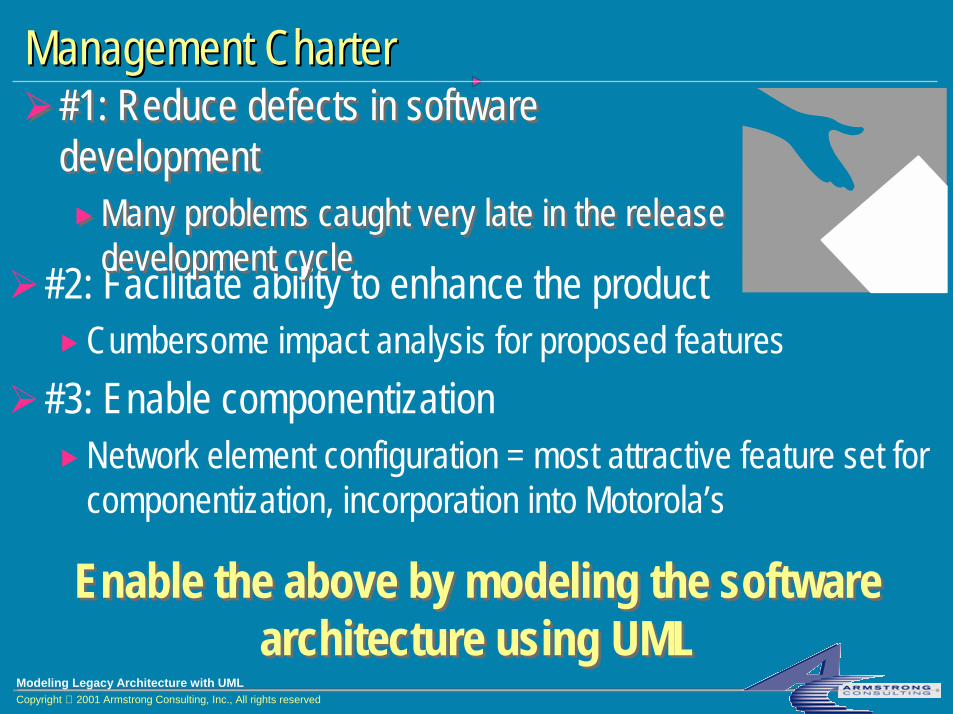
Management CharterManagement Charter
!#2: Facilitate ability to enhance the product!Cumbersome impact analysis for proposed features
!#3: Enable componentization!Network element configuration = most attractive feature set for
componentization, incorporation into Motorola’s
!#1: Reduce defects in software development!Many problems caught very late in the release
development cycle
!#1: Reduce defects in software development!Many problems caught very late in the release
development cycle
Enable the above by modeling the software architecture using UML
Enable the above by modeling the software architecture using UML

Modeling Legacy Architecture with UMLCopyright 2001 Armstrong Consulting, Inc., All rights reserved
Stakeholder RequestsStakeholder Requests! Management
! Previous slide! Provide basis for establishing formal architectural analysis into the
software development workflow! Architects
! Big picture of the system: major components & structures, relationships between them
! Support impact analysis for adding new features! Context for documenting, developing and educating others about the
system! Single-source repository for all architectural and design artifacts

Modeling Legacy Architecture with UMLCopyright 2001 Armstrong Consulting, Inc., All rights reserved
Stakeholder Requests Stakeholder Requests (cont’d)(cont’d)
!Subsystem Leads!Show how subsystems interact on a high level!Provide clear definition of subsystem boundaries (interfaces
provided, interfaces required)!Support impact analysis for designing and implementing
new features!Context for educating new developers about the system
!Developers!Roadmap for learning the design of the system

Modeling Legacy Architecture with UMLCopyright 2001 Armstrong Consulting, Inc., All rights reserved
ChallengesChallenges! Non-OO source constructs
! Implementation of functional decomposition (!)! Sparsely documented C programs, stored procedures
! Design artifacts largely out of date! Wide variety of detail, format, completeness
! No analysis artifacts! Heterogeneous requirements artifacts
! Combine high-level requirements with low-level design! Many disparities and contradictions across artifacts! Architects new to the system
! No “gray-hairs” to rely on: everyone learning

Modeling Legacy Architecture with UMLCopyright 2001 Armstrong Consulting, Inc., All rights reserved
Existing Source ConstructsExisting Source Constructs
!C programs!Processes (EXE’s) communicating via modified IPC
!Asynchronous messaging simulating synchronous behavior via coded “wait” loops
!Large numbers of complex stored procedures!Several hundred business rules
!No traceability to design, implementation: all done by hand analysis

Modeling Legacy Architecture with UMLCopyright 2001 Armstrong Consulting, Inc., All rights reserved
Status: 4+1 View of ArchitectureStatus: 4+1 View of Architecture
Process View Deployment View
Logical View
Use-Case View
Implementation View
End-user Functionality
PerformanceScalabilityThroughput
System integratorsSystem topology
Delivery, installationcommunication
System engineering
Analysts/DesignersStructure
ProgrammersSoftware management

Modeling Legacy Architecture with UMLCopyright 2001 Armstrong Consulting, Inc., All rights reserved
!Use Case View!System functionality poorly documented from an outside
perspective!No visual modeling
!Logical View!No analysis model: everyone has their own concept of key
abstractions!Design model spotty, mostly textual and very detailed
Status: 4+1 View of Architecture Status: 4+1 View of Architecture (cont’d)(cont’d)
Use-Case View
End-user Functionality
LogicalView
Analysts/DesignersStructure

Modeling Legacy Architecture with UMLCopyright 2001 Armstrong Consulting, Inc., All rights reserved
Status: 4+1 View of Architecture Status: 4+1 View of Architecture (cont’d)(cont’d)
! Implementation View!Software constructs already in place, so not a priority
!Process View!Processes in place!Communication between them documented, but not up to
date
Implementation View
ProgrammersSoftware management
Process ViewPerformanceScalabilityThroughput
System integrators

Modeling Legacy Architecture with UMLCopyright 2001 Armstrong Consulting, Inc., All rights reserved
Status: 4+1 View of Architecture Status: 4+1 View of Architecture (cont’d)(cont’d)
!Deployment View!Very well understood!Fairly well documented
Deployment View
System topologyDelivery, installation
communication
System engineering

Modeling Legacy Architecture with UMLCopyright 2001 Armstrong Consulting, Inc., All rights reserved
ApproachApproach!Raise the level of abstraction
!Focus on Use Case View and Logical View!Gain agreement on basic functionality, key concepts!Define modeling levels
!What will be in the Logical View?!Adapt and extend UML as needed!Work top-down and bottom-up simultaneously
!Top-down: create requirements artifacts, analyze from there!Bottom-up: start with existing code, abstract upward

Modeling Legacy Architecture with UMLCopyright 2001 Armstrong Consulting, Inc., All rights reserved
TopTop--down Effortdown Effort! Existing system = implementation of functional decomposition
(!)! Use Case modeling
! Looked to user interface for Use Cases! Actors fairly readily identified! Challenge: keep Use Cases at a high enough level, yet with enough
detail to decide which are architecturally significant! Analysis Modeling/Use Case Realizations
! Big challenge: no agreement on key abstractions (big surprise to team members)
! Very difficult to separate conceptual entities from implementation

Modeling Legacy Architecture with UMLCopyright 2001 Armstrong Consulting, Inc., All rights reserved
BottomBottom--up Effortup Effort
!Goal: meet the top-down model somewhere in the middle
!Where to start? What equals a UML “splat” (classifier)?
Three major tries at this...Three major tries at this...

Modeling Legacy Architecture with UMLCopyright 2001 Armstrong Consulting, Inc., All rights reserved
Try #1: C Program Try #1: C Program ≅≅ UML ClassUML Class
!C program is a collection of (more or less) related functions!Corollary to class with operations
!State is an issue!State captured in files, tables, other data structures: requires
further modeling conventions

Modeling Legacy Architecture with UMLCopyright 2001 Armstrong Consulting, Inc., All rights reserved
Class DiagramsClass Diagrams
!C function = operation on class!Parameters = function parameters
!No attributes: programs themselves are stateless!Structural relationships
!No instances, so association, aggregation, composition are irrelevant
!Dependencies between caller & “callee” (next slides…)<<C program>>
sys_dist.c
abort_dist(…)val_dist_acg(…)
<<C program>>dist_mgr.c

Modeling Legacy Architecture with UMLCopyright 2001 Armstrong Consulting, Inc., All rights reserved
! Interaction diagrams!Message = invocation of function in another C program
Interaction DiagramsInteraction Diagrams
: sys_dist.c: dist_mgr.c
val_dist_acg(…)

Modeling Legacy Architecture with UMLCopyright 2001 Armstrong Consulting, Inc., All rights reserved
PackagesPackages
!Packages!Package structure parallels UNIX directory structure!Package dependencies required significant hand analysis of
code

Modeling Legacy Architecture with UMLCopyright 2001 Armstrong Consulting, Inc., All rights reserved
Rose Demo: C Programs as UML ClassesRose Demo: C Programs as UML Classes

Modeling Legacy Architecture with UMLCopyright 2001 Armstrong Consulting, Inc., All rights reserved
Evaluation of Try #1Evaluation of Try #1
!Pro:! “Classes” easy to identify!Automatic reverse engineering
! Custom program converts C headers to C++ format! Rose C++ reverse engineering capability! Interaction diagramming easily done in Rose

Modeling Legacy Architecture with UMLCopyright 2001 Armstrong Consulting, Inc., All rights reserved
Evaluation of Try #1 Evaluation of Try #1 (cont’d)(cont’d)
!Con:!Too many classes: not an effective big picture!Not architectural in nature: too constrained by
implementation!Doesn’t effectively show communication between larger
constructs!Doesn’t yield new information
! Code profiling tools, UNIX commands, MAKE files just as effective

Modeling Legacy Architecture with UMLCopyright 2001 Armstrong Consulting, Inc., All rights reserved
Try #2: OMCTry #2: OMC--R Process R Process ≅≅ UML SubsystemUML Subsystem!OMC-R process = EXE “instance”
!Process “contains” C programs!Processes communicate via IPC
!Motorola-extended version of standard IPC! Implemented as C functions making calls to common IPC
library: parameters include receiving process ID, message ID and message parameters
ipc_mq_send_msg ( <receiver ID>, LMGI_I_CMD_MSG, … )Sender code fragment (inside LMUI process):
Receiver code fragment (inside LMGI process):ipc_mq_receive_msg ( <my process ID>, LMGI_I_CMD_MSG, … )

Modeling Legacy Architecture with UMLCopyright 2001 Armstrong Consulting, Inc., All rights reserved
Class DiagramsClass Diagrams
!Subsystem encapsulation parallels implementation!C programs make direct function calls only to other C
programs within the same containing process!Calls to other processes requires IPC call
! Interface = functionally coupled set of IPC messages received by contained C programs! Interfaces are purely conceptual: no direct physical
counterpart<<interface>>iLMGI_Download Manager
<<IPC>> LMGI_R_ISOCHK_MSG ( )<<IPC>> LMGI_I_RMV_MSG ( )<<IPC>> LMGI_I_CMD_MSG ( )
<<subsystem>LMGI

Modeling Legacy Architecture with UMLCopyright 2001 Armstrong Consulting, Inc., All rights reserved
Class DiagramsClass Diagrams (cont’d)(cont’d)
!Subsystem dependency: C program inside a sub-system sends IPC message to some other process
!Sender and receiver both dependent on IPC subsystem
<<subsystem>LMUI
<<subsystem>LMGI
iLMGI_Download Manager
<<subsystem>IPC subsystem
iIPC
Modeling Legacy Architecture with UMLCopyright 2001 Armstrong Consulting, Inc., All rights reserved
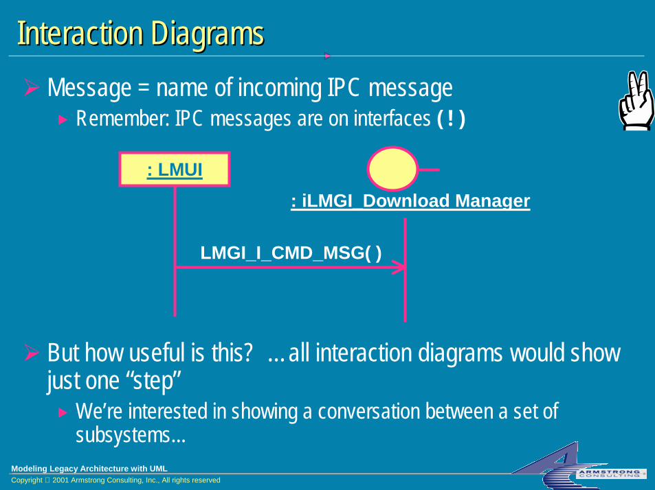
! Message = name of incoming IPC message! Remember: IPC messages are on interfaces ( ! )
! But how useful is this? …all interaction diagrams would show just one “step”! We’re interested in showing a conversation between a set of
subsystems...
Interaction DiagramsInteraction Diagrams
: LMUI
LMGI_I_CMD_MSG( )
: iLMGI_Download Manager

Modeling Legacy Architecture with UMLCopyright 2001 Armstrong Consulting, Inc., All rights reserved
Subsystem Interaction DiagramsSubsystem Interaction Diagrams! Rose can’t show subsystem directly on an interaction diagram! “Subsystem stand-ins” solve the problem
! Subsystem stand-in = class the realizes same set of interfaces that the subsystem realizes
<<subsystem>LMGI
LMGI stand-in<<subsystem stand-in>>
iLMGI_Download Manager
Additional Class Diagram:

Modeling Legacy Architecture with UMLCopyright 2001 Armstrong Consulting, Inc., All rights reserved
Subsystem Interaction DiagramsSubsystem Interaction Diagrams! Interaction diagram using subsystem stand-ins:
! This is a non-standard (non-RUP) interaction diagram! Combines external view of subsystems receiving messages with
internal view of interface message realizations ! !! But it models what we wanted to show ! !
: LMGI stand-in: LMUI stand-in
LMGI_I_CMD_MSG( )
: DL stand-in
DL_I_DLSTRQ_MSG( )

Modeling Legacy Architecture with UMLCopyright 2001 Armstrong Consulting, Inc., All rights reserved
Rose Demo: Processes as UML SubsystemsRose Demo: Processes as UML Subsystems

Modeling Legacy Architecture with UMLCopyright 2001 Armstrong Consulting, Inc., All rights reserved
Evaluation of Try #2Evaluation of Try #2! Pro:
! Larger-grained picture = helpful! Grouping IPC messages into interfaces = helpful! Can flesh out subsystem realizations as needed for understanding! Interaction diagrams (using subsystem stand-ins) = useful
! Con:! Processes still too fine-grained and implementation-constrained! Stakeholders want info on incoming AND outgoing messages! Architecture should show “externally visible properties”
! Received messages are only part of the story

Modeling Legacy Architecture with UMLCopyright 2001 Armstrong Consulting, Inc., All rights reserved
Try #3: “Subsystem” Try #3: “Subsystem” ≅≅ Conceptual ComponentConceptual Component!OMC-R “subsystems”: larger conceptual chunks
! “Subsystem” (“TNM functional area”) = a collection of C programs
!Run in (perhaps) several processes!Are functionally distinct!Conceptually layered
! Application (CM, FM, PM)! Infrastructure (IPC, SNMP, event handling) = collections of
implemented architectural mechanisms!Communicate strictly via IPC messages!Arguably “own” important data structures/stores (state)

Modeling Legacy Architecture with UMLCopyright 2001 Armstrong Consulting, Inc., All rights reserved
NotationNotation
!Blend of two sources:!Applied Software Architecture by Hofmeister, Nord & Soni!Rational’s UML Profile for Real-time Modeling
!Concepts:! component! port! connector! protocol! binding

Modeling Legacy Architecture with UMLCopyright 2001 Armstrong Consulting, Inc., All rights reserved
Conceptual ComponentConceptual Component
!UML definition: “a physical, replaceable part of a system that packages implementation and conforms to and provides the realizations of a set of interfaces”
!Conceptual component:! is conceptual, not (necessarily) physical! decomposable into other components
<<ccomponent>>Load Mgmt
Load Mgmt
Elided notation Canonic notation

Modeling Legacy Architecture with UMLCopyright 2001 Armstrong Consulting, Inc., All rights reserved
PortPort
!An interaction point for a conceptual component! In context of a particular collaboration with another
component! Is different from a UML interface in that it:
! defines both incoming and outgoing messages!may have its own implementation! is associated with a protocol that mandates how the
incoming and outgoing messages can be ordered

Modeling Legacy Architecture with UMLCopyright 2001 Armstrong Consulting, Inc., All rights reserved
PortPort (cont’d)(cont’d)
<<ccomponent>>LMGILMGI
Elided notation Canonic notation
Download Control
<<cport>>Download Control

Modeling Legacy Architecture with UMLCopyright 2001 Armstrong Consulting, Inc., All rights reserved
ConnectorConnector
!Represents a communication channel between two ports that play complementary roles in a protocol
! Is different from a UML association in that it! connects ports instead of classes! places the protocol restriction on the ports that it connects

Modeling Legacy Architecture with UMLCopyright 2001 Armstrong Consulting, Inc., All rights reserved
Class Diagram: Components, Ports, ConnectorsClass Diagram: Components, Ports, Connectors
LMGI
Elided notation:Download
ControlDownload Ack
LMUI
<<ccomponent>>LMGI
<<cport>>Download Control
<<ccomponent>>LMUI
<<cport>>Download Ack
Canonic notation:
<<cconnector>>
Modeling Legacy Architecture with UMLCopyright 2001 Armstrong Consulting, Inc., All rights reserved
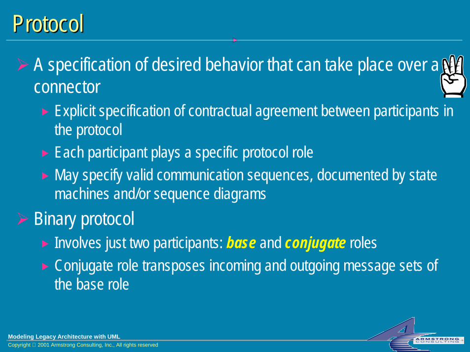
ProtocolProtocol! A specification of desired behavior that can take place over a
connector! Explicit specification of contractual agreement between participants in
the protocol! Each participant plays a specific protocol role! May specify valid communication sequences, documented by state
machines and/or sequence diagrams! Binary protocol
! Involves just two participants: base and conjugate roles! Conjugate role transposes incoming and outgoing message sets of
the base role
Modeling Legacy Architecture with UMLCopyright 2001 Armstrong Consulting, Inc., All rights reserved
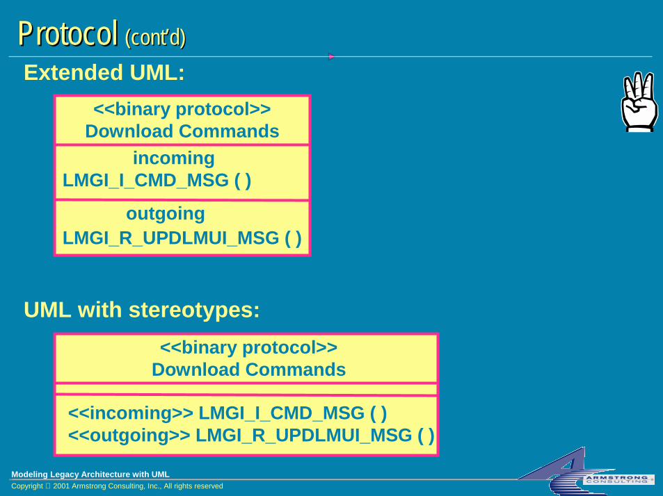
ProtocolProtocol (cont’d)(cont’d)
LMGI_R_UPDLMUI_MSG ( )
LMGI_I_CMD_MSG ( )incoming
outgoing
Download Commands<<binary protocol>>
<<outgoing>> LMGI_R_UPDLMUI_MSG ( )<<incoming>> LMGI_I_CMD_MSG ( )
Download Commands<<binary protocol>>
Extended UML:
UML with stereotypes:

Modeling Legacy Architecture with UMLCopyright 2001 Armstrong Consulting, Inc., All rights reserved
Class Diagram: Ports and ProtocolsClass Diagram: Ports and Protocols<<cport>>
Download Control<<cport>>
Download Ack<<cconnector>>
<<outgoing>> LMGI_R_UPDLMUI_MSG ( )<<incoming>> LMGI_I_CMD_MSG ( )
Download Commands<<binary protocol>>
<<obeys>> <<obeys conjugate>>We use stereotyped “realizes” relationships so that ports “inherit” the operations from the protocol

Modeling Legacy Architecture with UMLCopyright 2001 Armstrong Consulting, Inc., All rights reserved
Class Diagram: Rose SupportClass Diagram: Rose Support
<<ccomponent>>LMGI
<<cport>>Download Control
<<outgoing>> LMGI_R_UPDLMUI_MSG ( )<<incoming>> LMGI_I_CMD_MSG ( )
Download Commands<<binary protocol>>
<<obeys>>Extra “realizes” relationship required: allows us to draw interaction diagrams where components send messages to one another
<<Rose support>>

Modeling Legacy Architecture with UMLCopyright 2001 Armstrong Consulting, Inc., All rights reserved
Interaction Diagrams (new slide!!)Interaction Diagrams (new slide!!)
! I’ll show an example in Rose here…

Modeling Legacy Architecture with UMLCopyright 2001 Armstrong Consulting, Inc., All rights reserved
Notation: ScalabilityNotation: Scalability
LMGI
NE Status
LMUI
Load Management
Elided notation:
Canonic notation (component containment excerpt):
<<ccomponent>>Load Management
<<ccomponent>>LMGI
<<ccomponent>>LMGI

Modeling Legacy Architecture with UMLCopyright 2001 Armstrong Consulting, Inc., All rights reserved
Notation: Port BindingNotation: Port Binding
LMGI NE Status
Load Management
Elided notation:
NE Status
! Port of enclosed component may be bound to port of enclosing component! Enclosing component’s port may or may not obey the exact same
protocol as enclosed component’s port obeys! Multiple ports from enclosed components may bind to a single port
of an enclosing component
! Port of enclosed component may be bound to port of enclosing component! Enclosing component’s port may or may not obey the exact same
protocol as enclosed component’s port obeys! Multiple ports from enclosed components may bind to a single port
of an enclosing component

Modeling Legacy Architecture with UMLCopyright 2001 Armstrong Consulting, Inc., All rights reserved
Notation: Port BindingNotation: Port Binding (cont’d)(cont’d)
Canonic notation: <<ccomponent>>Load Management
<<ccomponent>>LMGI
<<cport>>NE Status(from LMGI)
<<cport>>NE Status
(from Load Management)
<<cbinding>>

Modeling Legacy Architecture with UMLCopyright 2001 Armstrong Consulting, Inc., All rights reserved
Rose Demo: Conceptual ComponentsRose Demo: Conceptual Components

Modeling Legacy Architecture with UMLCopyright 2001 Armstrong Consulting, Inc., All rights reserved
Evaluation of Try #3Evaluation of Try #3! Pro:
! Notation is conceptually scaleable! Captures constraints on interactions between components! Fits with the real-time, asynchronous nature of OMC-R system! Provides big-picture view of system
! Con:! Difficult to model in Rose: Rose Realtime is better, but UML
stereotypes mean somewhat different things! Interaction diagrams difficult, error-prone! Modeling state is still a big issue

Modeling Legacy Architecture with UMLCopyright 2001 Armstrong Consulting, Inc., All rights reserved
Modified 4+1 View of ArchitectureModified 4+1 View of Architecture! Use Case View
! Captured functional requirements separate from solutions! Logical View
! Analysis model! Crucial element for gaining understanding, agreement on the fundamental
system concepts! Architectural model
! High-level functional abstractions in the solution space! Design model
! Combination of abstract elements and concrete elements directly traceable to code
! Process, Implementation, Deployment Views

Modeling Legacy Architecture with UMLCopyright 2001 Armstrong Consulting, Inc., All rights reserved
Summary ReflectionsSummary Reflections!Architectural modeling is an immature art
!Many different approaches, all have strengths and weaknesses
!Modeling non-OO constructs with UML presents special challenges!We couldn’t find anyone else who was doing this…!How to capture state?
!Visual modeling with Rose!Complicated diagrams!Model organization is crucial (deep package structure)

Modeling Legacy Architecture with UMLCopyright 2001 Armstrong Consulting, Inc., All rights reserved
Summary ReflectionsSummary Reflections (cont’d)(cont’d)
!Extended UML notation for architectural modeling!Conceptual modeling was very useful, scaleable! Lower-level modeling (Hofmeister/Nord/Soni’s Module and
Execution views) was confusing, so we omitted it!The notational conventions we ultimately adopted served
main purpose of showing big picture of legacy architecture!Ongoing refinement of notational conventions
! In short: if it promotes clarity, use it; else leave it out

Modeling Legacy Architecture with UMLCopyright 2001 Armstrong Consulting, Inc., All rights reserved
QuestionsQuestions
Thank you for your attention and participation!


