1
Mobile robot electronic system with a network and
micro-controller based interface
Filipe Campos Meira Castro [email protected]
António Fernando Macedo Ribeiro [email protected]
Günther Starke [email protected]
Christoph Dreyer [email protected]
Universidade do Minho, Departamento de Electrónica Industrial, Guimarães, Portugal [11]
APS – European Center for Mechatronics, Aachen, Germany[12]
Abstract - This paper describes the electronic system used to a
mobile tank-robot and the network and micro-controlled based interface proceeding to drive it.
Key Words – Tank Robot, Client/Server, Qt, Atmega16,
Encoder, MD03 Driver, I2C (Inter Integrated Circuit)
I. INTRODUCTION
The key objective was to design and develop an embedded
system able to control a mobile platform. I2C communications
drives and encoders reading were developed using ATMega
microcontroller technology and Client/Server protocol carried
out using Qt libraries.
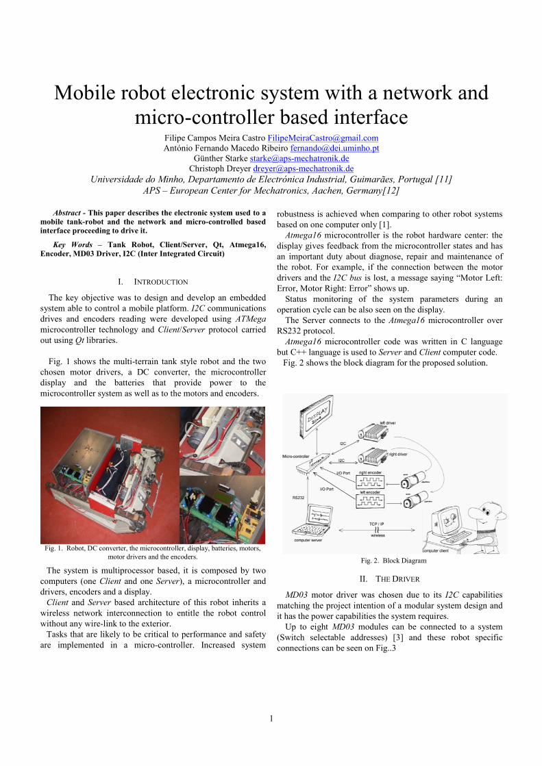
Fig. 1 shows the multi-terrain tank style robot and the two
chosen motor drivers, a DC converter, the microcontroller
display and the batteries that provide power to the
microcontroller system as well as to the motors and encoders.
The system is multiprocessor based, it is composed by two
computers (one Client and one Server), a microcontroller and
drivers, encoders and a display.
Client and Server based architecture of this robot inherits a
wireless network interconnection to entitle the robot control
without any wire-link to the exterior.
Tasks that are likely to be critical to performance and safety
are implemented in a micro-controller. Increased system
robustness is achieved when comparing to other robot systems
based on one computer only [1].
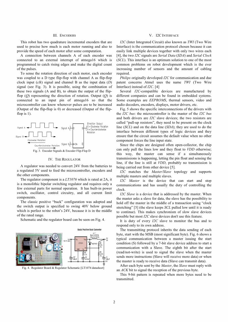
Atmega16 microcontroller is the robot hardware center: the
display gives feedback from the microcontroller states and has
an important duty about diagnose, repair and maintenance of
the robot. For example, if the connection between the motor
drivers and the I2C bus is lost, a message saying “Motor Left:
Error, Motor Right: Error” shows up.
Status monitoring of the system parameters during an
operation cycle can be also seen on the display.
The Server connects to the Atmega16 microcontroller over
RS232 protocol.
Atmega16 microcontroller code was written in C language
but C++ language is used to Server and Client computer code.
Fig. 2 shows the block diagram for the proposed solution.
II. THE DRIVER
MD03 motor driver was chosen due to its I2C capabilities
matching the project intention of a modular system design and
it has the power capabilities the system requires.
Up to eight MD03 modules can be connected to a system
(Switch selectable addresses) [3] and these robot specific
connections can be seen on Fig..3
Fig. 1. Robot, DC converter, the microcontroller, display, batteries, motors,
motor drivers and the encoders. Fig. 2. Block Diagram
2
III. ENCODERS
This robot has two quadrature incremental encoders that are
used to precise how much is each motor running and also to
provide the speed of each motor after some computation.
A connection between channels A of each encoder was
connected to an external interrupt of atmega16 which is
programmed to catch rising edges and make the digital count
of the pulses.
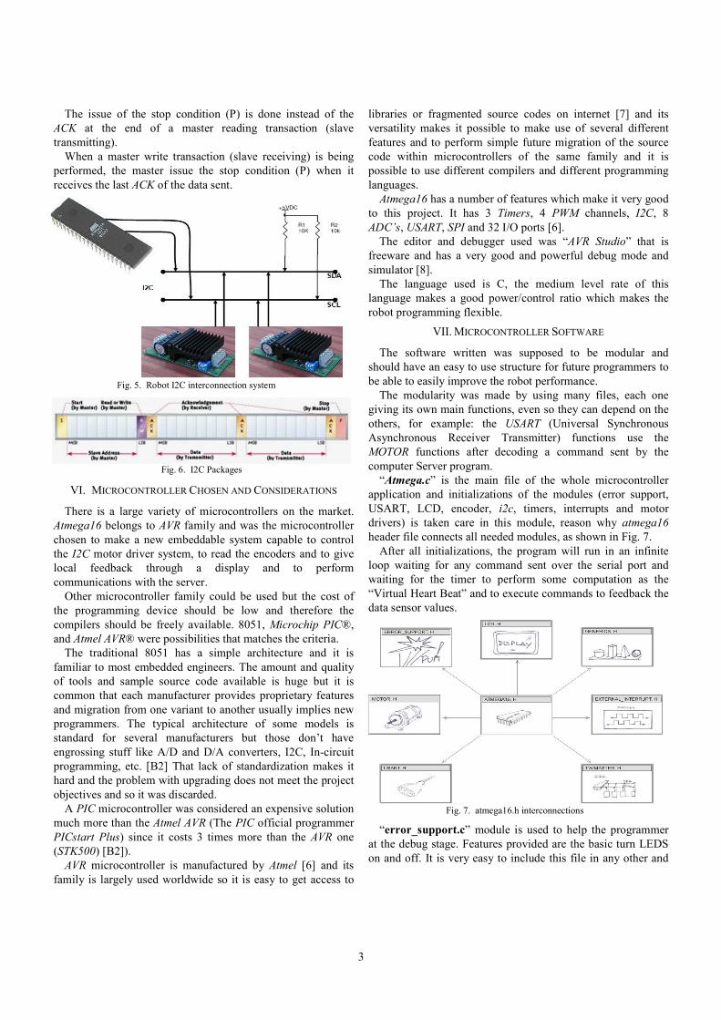
To sense the rotation direction of each motor, each encoder
was coupled to a D type flip-flop with channel A as flip-flop
clock input (clk) signal and channel B as the input data (D)
signal (see Fig. 3). It is possible, using the combination of
these two signals (A and B), to obtain the output of the flip-
flop (Q) representing the direction of rotation. Output (Q) is
connected to an input pin of atmega16 so that the
microcontroller can know whenever pulses are to be increased
(Output of the flip-flop is 0) or decreased (Output of the flip-
flop is 1).
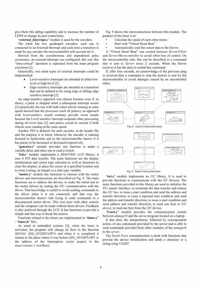
IV. THE REGULATOR
A regulator was needed to convert 24V from the batteries to
a regulated 5V used to feed the microcontroller, encoders and
the other components.
The regulator component is a LT1076 which is rated at 2A, it
is a monolithic bipolar switching regulator and requires only a
few external parts for normal operation. It has built-in power
switch, oscillator, control circuitry, and all current limit
components.
The classic positive “buck” configuration was adopted and
the switch output is specified to swing 40V below ground
which is perfect to the robot’s 24V, because it is in the middle
of the rated range.
Schematic and the regulator board can be seen on Fig. 4.
V. I2C INTERFACE
I2C (Inter Integrated Circuit) also known as TWI (Two Wire
Interface) is the communication protocol chosen because it can
easily link multiple devices together with only two wires each
[4], the two I2C signals are Serial Data (SDA) and Serial Clock
(SCL). This interface is an optimum solution to one of the most
common problems on robot development which is the ever
increasing number of sensors and the amount of cabling
required.
Philips originally developed I2C for communication and due
patent concerns Atmel uses the name TWI (Two Wire
Interface) instead of I2C. [4]
Several I2C-compatible devices are manufactured by
different companies and can be found in embedded systems.
Some examples are EEPROMS, thermal sensors, video and
audio decoders, encoders, displays, motor drivers, etc.
Fig. 5 shows the specific interconnections of the drivers with
the I2C bus: the microcontroller is the master of the I2C bus
and both drivers are I2C slave devices; the two resistors are
called “pull-up resistors”, they need to be present on the clock
line (SCL) and on the data line (SDA); they are used to do the
interface between different types of logic devices and they
ensure that the circuit assumes the default value when no other
component forces the line input state.
Since the chips are designed often open-collector, the chip
can only pull the lines low and they float to VDD otherwise;
this way, the master can sense if a simultaneously
transmissions is happening, letting the pin float and sensing the
line, if the line is still at VDD, probably no transmission is
being carried out from other device [5].
I2C matches the Master/Slave topology and supports
multiple masters and multiple slaves.
I2C Master is the device that can start and stop
communications and has usually the duty of controlling the
clock.
I2C Slave is a device that is addressed by the master. When
the master asks a slave for data, the slave has the possibility to
hold off the master in the middle of a transaction using “clock
stretching” [5] (the slave keeps SCL pulled low until it is ready
to continue). This makes synchronism of slow slave devices
possible but most I2C slave devices don't use this feature.
It is duty of every I2C slave to monitor the bus and to
respond only to its own address.
The transmitting protocol inherits the data sending of each
byte, start with the MSB (most significant byte). Fig. 6 shows a
typical communication between a master issuing the start
condition (S) followed by a 7-bit slave device address to start a
communication with a Slave. The eighth bit after the start
(read/not-write) is used to signal the slave when the master
sends more instructions (Slave will receive more data) or when
the master is ready to receive data (Slave can transmit data).
After each byte sent by the Master, the Slave must reply with
an ACK bit to signal the reception of the previous byte.
This 9-bit pattern is repeated when more bytes need to be
transmitted.
Fig. 3. Encoder Signals & Encoder Flip-Flop D
Fig. 4. Regulator Board & Regulator Schematic [LT1074 datasheet]
3
The issue of the stop condition (P) is done instead of the
ACK at the end of a master reading transaction (slave
transmitting).
When a master write transaction (slave receiving) is being
performed, the master issue the stop condition (P) when it
receives the last ACK of the data sent.
VI. MICROCONTROLLER CHOSEN AND CONSIDERATIONS
There is a large variety of microcontrollers on the market.
Atmega16 belongs to AVR family and was the microcontroller
chosen to make a new embeddable system capable to control
the I2C motor driver system, to read the encoders and to give
local feedback through a display and to perform
communications with the server.
Other microcontroller family could be used but the cost of
the programming device should be low and therefore the
compilers should be freely available. 8051, Microchip PIC®,
and Atmel AVR® were possibilities that matches the criteria.
The traditional 8051 has a simple architecture and it is
familiar to most embedded engineers. The amount and quality
of tools and sample source code available is huge but it is
common that each manufacturer provides proprietary features
and migration from one variant to another usually implies new
programmers. The typical architecture of some models is
standard for several manufacturers but those don’t have
engrossing stuff like A/D and D/A converters, I2C, In-circuit
programming, etc. [B2] That lack of standardization makes it
hard and the problem with upgrading does not meet the project
objectives and so it was discarded.
A PIC microcontroller was considered an expensive solution
much more than the Atmel AVR (The PIC official programmer
PICstart Plus) since it costs 3 times more than the AVR one
(STK500) [B2]).
AVR microcontroller is manufactured by Atmel [6] and its
family is largely used worldwide so it is easy to get access to
libraries or fragmented source codes on internet [7] and its
versatility makes it possible to make use of several different
features and to perform simple future migration of the source
code within microcontrollers of the same family and it is
possible to use different compilers and different programming
languages.
Atmega16 has a number of features which make it very good
to this project. It has 3 Timers, 4 PWM channels, I2C, 8
ADC’s, USART, SPI and 32 I/O ports [6].
The editor and debugger used was “AVR Studio” that is
freeware and has a very good and powerful debug mode and
simulator [8].
The language used is C, the medium level rate of this
language makes a good power/control ratio which makes the
robot programming flexible.
VII. MICROCONTROLLER SOFTWARE
The software written was supposed to be modular and
should have an easy to use structure for future programmers to
be able to easily improve the robot performance.
The modularity was made by using many files, each one
giving its own main functions, even so they can depend on the
others, for example: the USART (Universal Synchronous
Asynchronous Receiver Transmitter) functions use the
MOTOR functions after decoding a command sent by the
computer Server program.
“Atmega.c” is the main file of the whole microcontroller
application and initializations of the modules (error support,
USART, LCD, encoder, i2c, timers, interrupts and motor
drivers) is taken care in this module, reason why atmega16
header file connects all needed modules, as shown in Fig. 7.
After all initializations, the program will run in an infinite
loop waiting for any command sent over the serial port and
waiting for the timer to perform some computation as the
“Virtual Heart Beat” and to execute commands to feedback the
data sensor values.
“error_support.c” module is used to help the programmer
at the debug stage. Features provided are the basic turn LEDS
on and off. It is very easy to include this file in any other and
Fig. 5. Robot I2C interconnection system
Fig. 6. I2C Packages
Fig. 7. atmega16.h interconnections
4
give them this debug capability and to increase the number of
LEDS or change its port connections.
“external_interrupt.c” module is used for the encoders.
The robot has two quadruped encoders, each one is
connected to an External Interrupt and each time a transition is
made by any encoder the microcontroller will account for it.
Derived from the asynchronous and unpredicted pulse
occurrence, an external interrupt was configured, this way this
“time-critical” operation is separated from the main program
execution [2].
Generically, two main types of external interrupts could be
implemented:
• Level-sensitive interrupts are attended at either low-
level or high-level [2].
• Edge-sensitive interrupts are attended at a transition
that can be defined to be rising edge or falling edge
sensitive interrupt [2].
An edge-sensitive approach was chosen because even if, in
theory, a pulse is skipped when a subsequent interrupt occurs
[2] (practically the test with both robot wheels running at same
speed showed that the processor catch all pulses); an approach
with level-sensitive would certainty provide worst results
because the Level sensitive interrupt suspends other processing
during all level time [2] and pulses would be missed if both
wheels were running at the same speed.
Another PIN is defined, for each encoder, at the header file
and the purpose is to know whenever the encoder is running
forward or backwards and so the microcontroller knows if it
has pulses to be increased or decreased respectively.
“generics.c” module provides one function to make a
variable delay and other one to read a switch.
“lcd.c” module implements a HD44780U LCD library; it
uses 4 PIN data transfer. The main functions are the display
initialization and cursor type selection as well as functions to
clear the display, to place the cursor at a specified location and
to write a string, an integer or a char type variable.
“motor.c” module has functions to interact with the motor
drivers and interconnections are described on Fig. 8. The main
functions are to address the drivers, to make the initial test to
the motor drivers by testing the I2C communication with the
driver. That knowledge is useful to avoid sending commands to
the driver when it is not connected, and that way the
microcontroller doesn’t halt trying to send commands to a
disconnected motor driver. This way tests with other sensors
and the computer can be made without these drivers. Feedback
is also archived through the LCD. It has functions to provide a
simple and fast way to break the motors.
Functions related to the timers are implemented in “timer.c”
/ “timer.h” files.
As usual at embedded systems [2], when the timer is
activated, the program will change its flow to the function
SIGNAL (SIG_OVERFLOW1) and when it is completed it
returns to the place where it was before (SIG_OVERFLOW1 is
the address of the interruption vector respect to the
timer/counter 1 overflow).
Fig. 9 shows the interconnections between this module. The
purpose of the timer is to:
• Calculate the speed of each robot motor.
• Deal with “Virtual Heart Beat”.
• Automatically send the sensor data to the Server.
A “Virtual Heart Beat” was created between Server/Client
and Server/Microcontroller to avoid robot loss of control. On
the microcontroller side, this can be described as a command
that is sent to Server every 2 seconds. When the Server
receives it has the duty to resend that command.
If, after four seconds, no acknowledge of the previous ping
is received then a command to stop the motors is sent by the
microcontroller to avoid damages caused by an uncontrolled
robot.
“twi.c” module implements an I2C library. It is used to
provide functions to communicate with the I2C devices. The
main functions provided in this library are used to initialize the
I2C master interface; to terminate the data transfer and release
the I2C bus; to issue a start condition and send the address and
transfer direction; to issue a repeated start condition and send
the address and transfer direction; to issue a start condition and
send address and transfer direction; to send one byte to I2C
device; to read one byte from the I2C device.
“Usart.c” module provides the communication system
between atmega16 and the server program located on a laptop.
It also does the interpretation, followed by correspondent
action, of any commands provided by the server and is able to
send commands provided from other modules of the atmega16
to the server.
The Serial Ports communication is dealt with functions that
provide the device initialization and sends a character or a
string using USART.
Fig. 8. motor.h interconnections
Fig. 9. timer.h interconnections
5
The command is interpreted and then executed. The
developed commands are used to send the sensors data to the
USART, data is relative to the “Virtual Heart Beat” and to each
motor, position, velocity, current and temperature.
VIII. PROTOCOL OF COMMUNICATION BETWEEN THE SERVER COMPUTER AND THE ATMEGA16
Each command received by the atmega16 USART, to be well
interpreted, must have at least one alphanumeric byte followed
by at least one numerical value and a ‘Z’ character to flag the
end of each command/value frame.
All characters must be in ASCII format.
Table I shows the word composition layout.
TABLE I WORD COMPOSITION LAYOUT
Word Composition nr. 1 ……. Word Composition nr. n
Function Value ‘Z’ ……. Function Value ‘Z’
x bytes y bytes 1 byte …… u bytes v bytes 1 byte
With this protocol the communication stability is archived
because if a lack of communication occurs, the command is
misunderstood but at least synchronism loss is avoided.
The flexibility is also archived by this method because
commands and values can have different sizes.
IX. PROTOCOL OF COMMUNICATION FROM THE ATMEGA16 TO THE SERVER COMPUTER
The protocol of sending data from atmega16 to the server
computer is different from the opposite direction.
The server wants either all sensors data or a considerable
amount of data and not just a specific value. Therefore, instead
of sending an extra character to signal the end of a specific
frame (like the ‘Z’ character in the communication from server
to the atmega16), the process is implemented to validate a
frame each time a new alphanumeric character appears. This
way, to process the last received frame, the server must receive
an extra frame: that last frame is “END0” and does nothing
except handling the possibility to the server know that previous
value received has been completed.
The “END0” frame is, in fact, an undefined command/value
by the server and so it can be replaced by any other appearance
as “E0” or any other undefined command/value.
After a command/value is identified another function is
called to execute it.
Resuming, atmega16 can send several sets of commands and
values with different sizes and when the server receives the
command/value “END0” it guarantees the process of the last
command/value.
To ensure a correct explanation of the whole communication
process, it needs to keep in mind that inherent the serial port
process, the operating system gets a variable amount of data
from the serial port buffer and the server applications get that
frame which can contain several sets of commands/value. To
deal with all amount and unpredictable data, every time the
server gets data, a copy to a new variable is done and a reset is
performed of the old buffer to a null value and starts the
process of indentifying commands/values. This way the buffer
does not get too long and the process of indentifying
commands/values has a static data within the process (the
buffer update is in other thread, reason why it has a dynamic
growth).
X. DESKTOP PROCESSING
The system proposed uses two computers based at a server-
client architecture. The client computer is not critical but the
server used is, at the moment, a common laptop although later
on it will be replaced by an industrial and low-power
consumption one.
Since the QT libraries are used, this system is platform
independent, which means that the operating system can be
Windows, Windows CE, MAC, LINUX or an embedded Linux
environment.
The necessity for a computer in the system is due to the
computer archive plug and play updates through USB ports,
can make some parallel computation and the space of a laptop
in the robot is not critical since the robot is large and a lot of
space is still free for other components.
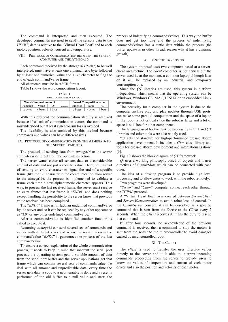
The language used for the desktop processing is C++ and QT
libraries and other tools were also widely used.
“Qt sets the standard for high-performance cross-platform
application development. It includes a C++ class library and
tools for cross-platform development and internationalization”
[9].
Fig. 10 shows the block diagram of QT framework.
Qt uses a working philosophy based on objects and it uses
directives of Signal/Slots which can be connected with each
other.
The idea of a desktop program is to provide high level
processing and to allow users to work with the robot remotely.
Two programs were developed:
“Server” and “Client” computer connect each other through
the TCP/IP protocol.
A “Virtual Heart Beat” was created between Server/Client
and Server/Microcontroller to avoid robot loss of control. In
the Client/Server concern, it can be described as a specific
command that is sent from the Server to the Client every 2
seconds. When the Client receives it, it has the duty to resend
that command.
If, after four seconds, no acknowledge of the previous
command is received then a command to stop the motors is
sent from the server to the microcontroller to avoid damages
caused by an uncontrolled robot.
XI. THE CLIENT
The client is used to transfer the user interface values
directly to the server and it is able to interpret incoming
commands proceeding from the server to provide users to
know the values of temperature and current of each motor
drives and also the position and velocity of each motor.
6
Client also to interpret the “Virtual Heart Beat” between the
server and the client to avoid a loss of control of the robot
derived from a lack of energy that could turn off the wireless
router or even the client computer.
“Client” class makes possible to create a client based on an
IP address and a PORT by use of its constructor.
Functions to make possible to send a QString to the server
are provide as well as respective Signals that are also used to
provide a way to log the data sent by the client.
The client has a socket to receive data as well as respective
Signals; that signal is connected to a Slot that provides a way
to log the data received.
Others private Slots of each Client can be used to close a
connection, connect a server, close a connection, read, archive
socket errors, etc.
Client needs to interact with the Server in order to send
commands that the user wants the robot to have and needs to
listen to data from the Server, that data can be provided from
the robot sensors but it is the server that transmits it (if the
Server options are defined to).
The interface includes a QgroupBox named “Client” which
has Qbuttons to connect to an IP address that can be chosen
through a QlineEdit.
The data is sent as ASCII format and the protocol adopted
for command exchanged between the server and the client is
the same as from atmega16 to the server:
Several sets of commands and values with different sizes are
being concatenated every time a character is received and
when the word “END” appears the processing starts.
The client will interpret all commands/data it receives and
send it, one by one, to a function that will perform those
commands.
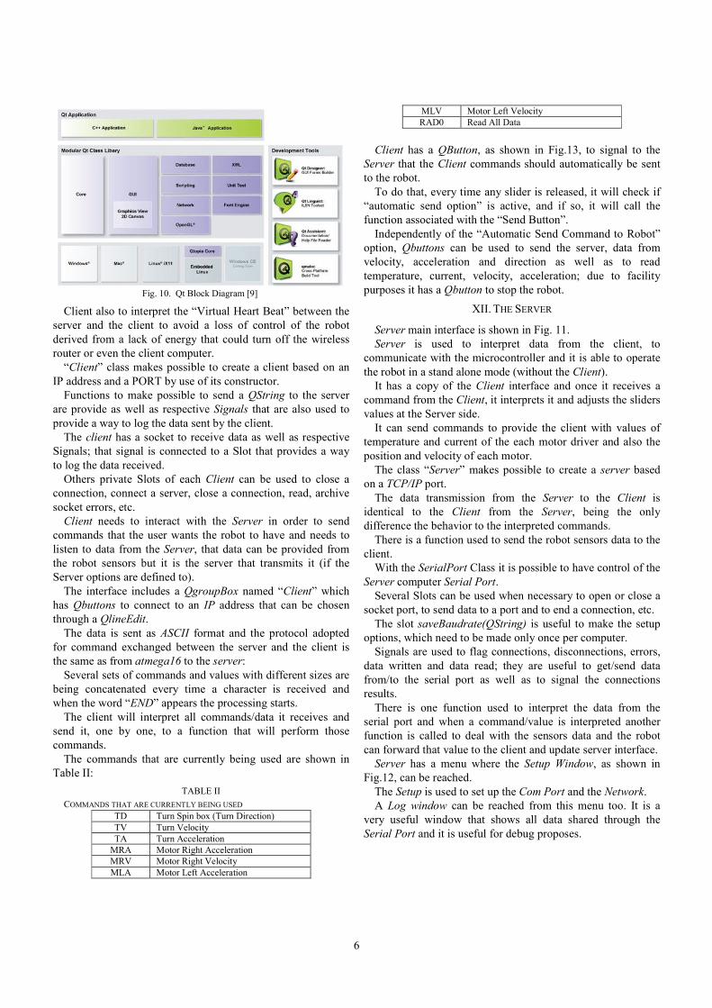
The commands that are currently being used are shown in
Table II:
TABLE II
COMMANDS THAT ARE CURRENTLY BEING USED TD Turn Spin box (Turn Direction)
TV Turn Velocity
TA Turn Acceleration
MRA Motor Right Acceleration
MRV Motor Right Velocity
MLA Motor Left Acceleration
MLV Motor Left Velocity
RAD0 Read All Data
Client has a QButton, as shown in Fig.13, to signal to the
Server that the Client commands should automatically be sent
to the robot.
To do that, every time any slider is released, it will check if
“automatic send option” is active, and if so, it will call the
function associated with the “Send Button”.
Independently of the “Automatic Send Command to Robot”
option, Qbuttons can be used to send the server, data from
velocity, acceleration and direction as well as to read
temperature, current, velocity, acceleration; due to facility
purposes it has a Qbutton to stop the robot.
XII. THE SERVER
Server main interface is shown in Fig. 11.
Server is used to interpret data from the client, to
communicate with the microcontroller and it is able to operate
the robot in a stand alone mode (without the Client).
It has a copy of the Client interface and once it receives a
command from the Client, it interprets it and adjusts the sliders
values at the Server side.
It can send commands to provide the client with values of
temperature and current of the each motor driver and also the
position and velocity of each motor.
The class “Server” makes possible to create a server based
on a TCP/IP port.
The data transmission from the Server to the Client is
identical to the Client from the Server, being the only
difference the behavior to the interpreted commands.
There is a function used to send the robot sensors data to the
client.
With the SerialPort Class it is possible to have control of the
Server computer Serial Port.
Several Slots can be used when necessary to open or close a
socket port, to send data to a port and to end a connection, etc.
The slot saveBaudrate(QString) is useful to make the setup
options, which need to be made only once per computer.
Signals are used to flag connections, disconnections, errors,
data written and data read; they are useful to get/send data
from/to the serial port as well as to signal the connections
results.
There is one function used to interpret the data from the
serial port and when a command/value is interpreted another
function is called to deal with the sensors data and the robot
can forward that value to the client and update server interface.
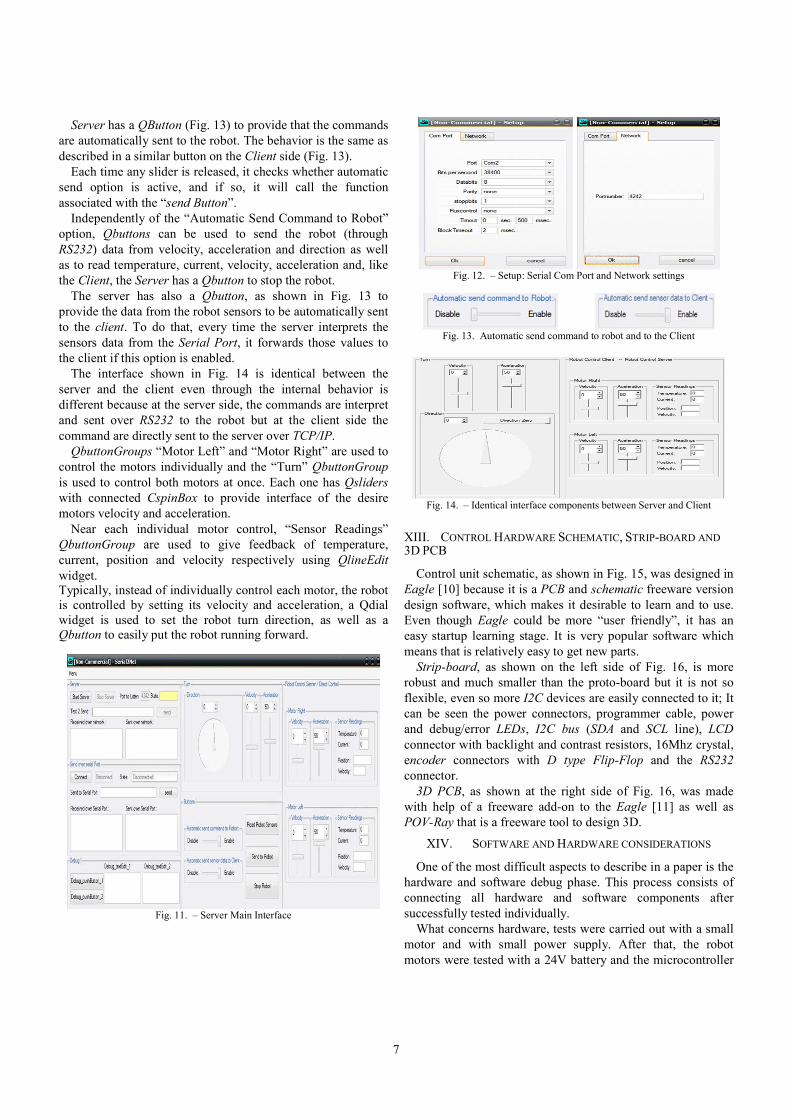
Server has a menu where the Setup Window, as shown in
Fig.12, can be reached.
The Setup is used to set up the Com Port and the Network.
A Log window can be reached from this menu too. It is a
very useful window that shows all data shared through the
Serial Port and it is useful for debug proposes.
Fig. 10. Qt Block Diagram [9]
7
Server has a QButton (Fig. 13) to provide that the commands
are automatically sent to the robot. The behavior is the same as
described in a similar button on the Client side (Fig. 13).
Each time any slider is released, it checks whether automatic
send option is active, and if so, it will call the function
associated with the “send Button”.
Independently of the “Automatic Send Command to Robot”
option, Qbuttons can be used to send the robot (through
RS232) data from velocity, acceleration and direction as well
as to read temperature, current, velocity, acceleration and, like
the Client, the Server has a Qbutton to stop the robot.
The server has also a Qbutton, as shown in Fig. 13 to
provide the data from the robot sensors to be automatically sent
to the client. To do that, every time the server interprets the
sensors data from the Serial Port, it forwards those values to
the client if this option is enabled.
The interface shown in Fig. 14 is identical between the
server and the client even through the internal behavior is
different because at the server side, the commands are interpret
and sent over RS232 to the robot but at the client side the
command are directly sent to the server over TCP/IP.
QbuttonGroups “Motor Left” and “Motor Right” are used to
control the motors individually and the “Turn” QbuttonGroup
is used to control both motors at once. Each one has Qsliders
with connected CspinBox to provide interface of the desire
motors velocity and acceleration.
Near each individual motor control, “Sensor Readings”
QbuttonGroup are used to give feedback of temperature,
current, position and velocity respectively using QlineEdit
widget. Typically, instead of individually control each motor, the robot
is controlled by setting its velocity and acceleration, a Qdial
widget is used to set the robot turn direction, as well as a
Qbutton to easily put the robot running forward.
Fig. 11. – Server Main Interface
Fig. 12. – Setup: Serial Com Port and Network settings
Fig. 13. Automatic send command to robot and to the Client
Fig. 14. – Identical interface components between Server and Client
XIII. CONTROL HARDWARE SCHEMATIC, STRIP-BOARD AND 3D PCB
Control unit schematic, as shown in Fig. 15, was designed in
Eagle [10] because it is a PCB and schematic freeware version
design software, which makes it desirable to learn and to use.
Even though Eagle could be more “user friendly”, it has an
easy startup learning stage. It is very popular software which
means that is relatively easy to get new parts.
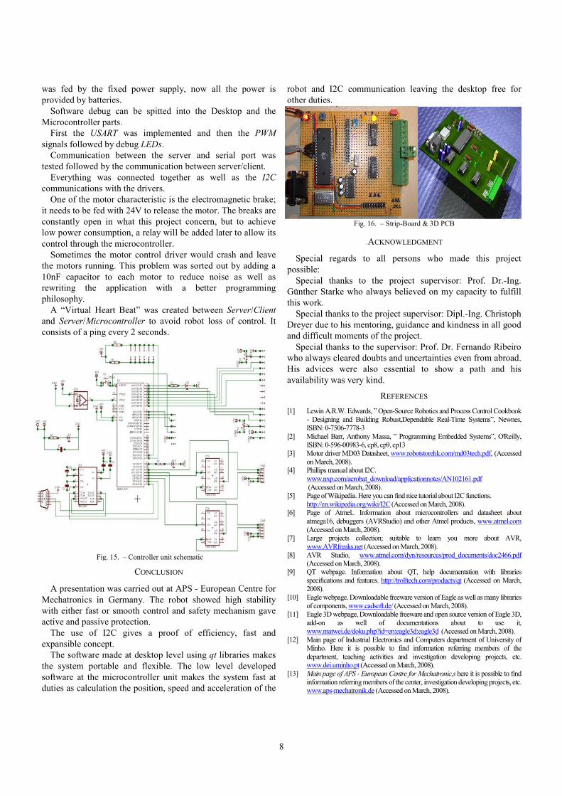
Strip-board, as shown on the left side of Fig. 16, is more
robust and much smaller than the proto-board but it is not so
flexible, even so more I2C devices are easily connected to it; It
can be seen the power connectors, programmer cable, power
and debug/error LEDs, I2C bus (SDA and SCL line), LCD
connector with backlight and contrast resistors, 16Mhz crystal,
encoder connectors with D type Flip-Flop and the RS232
connector.
3D PCB, as shown at the right side of Fig. 16, was made
with help of a freeware add-on to the Eagle [11] as well as
POV-Ray that is a freeware tool to design 3D.
XIV. SOFTWARE AND HARDWARE CONSIDERATIONS
One of the most difficult aspects to describe in a paper is the
hardware and software debug phase. This process consists of
connecting all hardware and software components after
successfully tested individually.
What concerns hardware, tests were carried out with a small
motor and with small power supply. After that, the robot
motors were tested with a 24V battery and the microcontroller
8
was fed by the fixed power supply, now all the power is
provided by batteries.
Software debug can be spitted into the Desktop and the
Microcontroller parts.
First the USART was implemented and then the PWM
signals followed by debug LEDs.
Communication between the server and serial port was
tested followed by the communication between server/client.
Everything was connected together as well as the I2C
communications with the drivers.
One of the motor characteristic is the electromagnetic brake;
it needs to be fed with 24V to release the motor. The breaks are
constantly open in what this project concern, but to achieve
low power consumption, a relay will be added later to allow its
control through the microcontroller.
Sometimes the motor control driver would crash and leave
the motors running. This problem was sorted out by adding a
10nF capacitor to each motor to reduce noise as well as
rewriting the application with a better programming
philosophy.
A “Virtual Heart Beat” was created between Server/Client
and Server/Microcontroller to avoid robot loss of control. It
consists of a ping every 2 seconds.
CONCLUSION
A presentation was carried out at APS - European Centre for
Mechatronics in Germany. The robot showed high stability
with either fast or smooth control and safety mechanism gave
active and passive protection.
The use of I2C gives a proof of efficiency, fast and
expansible concept.
The software made at desktop level using qt libraries makes
the system portable and flexible. The low level developed
software at the microcontroller unit makes the system fast at
duties as calculation the position, speed and acceleration of the
robot and I2C communication leaving the desktop free for
other duties.
.ACKNOWLEDGMENT
Special regards to all persons who made this project
possible:
Special thanks to the project supervisor: Prof. Dr.-Ing.
Günther Starke who always believed on my capacity to fulfill
this work.
Special thanks to the project supervisor: Dipl.-Ing. Christoph
Dreyer due to his mentoring, guidance and kindness in all good
and difficult moments of the project.
Special thanks to the supervisor: Prof. Dr. Fernando Ribeiro
who always cleared doubts and uncertainties even from abroad.
His advices were also essential to show a path and his
availability was very kind.
REFERENCES
[1] Lewin A.R.W. Edwards, ” Open-Source Robotics and Process Control Cookbook - Designing and Building Robust,Dependable Real-Time Systems”, Newnes,
ISBN: 0-7506-7778-3
[2] Michael Barr, Anthony Massa, ” Programming Embedded Systems”, O'Reilly, ISBN: 0-596-00983-6, cp8, cp9, cp13
[3] Motor driver MD03 Datasheet, www.robotstorehk.com/md03tech.pdf, (Accessed on March, 2008).
[4] Phillips manual about I2C.
www.nxp.com/acrobat_download/applicationnotes/AN102161.pdf
(Accessed on March, 2008). [5] Page of Wikipedia. Here you can find nice tutorial about I2C functions.
http://en.wikipedia.org/wiki/I2C (Accessed on March, 2008). [6] Page of Atmel.. Information about microcontrollers and datasheet about
atmega16, debuggers (AVRStudio) and other Atmel products, www.atmel.com
(Accessed on March, 2008). [7] Large projects collection; suitable to learn you more about AVR,
www.AVRfreaks.net (Accessed on March, 2008).
[8] AVR Studio, www.atmel.com/dyn/resources/prod_documents/doc2466.pdf (Accessed on March, 2008).
[9] QT webpage. Information about QT, help documentation with libraries
specifications and features. http://trolltech.com/products/qt (Accessed on March, 2008).
[10] Eagle webpage. Downloadable freeware version of Eagle as well as many libraries
of components, www.cadsoft.de/ (Accessed on March, 2008). [11] Eagle 3D webpage, Downloadable freeware and open source version of Eagle 3D,
add-on as well of documentations about to use it,
www.matwei.de/doku.php?id=en:eagle3d:eagle3d (Accessed on March, 2008). [12] Main page of Industrial Electronics and Computers department of University of
Minho. Here it is possible to find information referring members of the
department, teaching activities and investigation developing projects, etc. www.dei.uminho.pt (Accessed on March, 2008).
[13] Main page of APS - European Centre for Mechatronic,s here it is possible to find
information referring members of the center, investigation developing projects, etc. www.aps-mechatronik.de (Accessed on March, 2008).
Fig. 15. – Controller unit schematic
Fig. 16. – Strip-Board & 3D PCB


