Minto Mine
Mill Operations Plan
Prepared by:
Minto Explorations Ltd.
Minto Mine
June 2014

Minto Explorations Ltd. Minto Mine
2014 Mill Operations Plan
June 2014 i
Table of Contents
1 Introduction ...............................................................................................................................1
1.1 Project Description .......................................................................................................................... 1
2 Mill and Ancillary Facilities ..........................................................................................................3
2.1 Mill Facilities .................................................................................................................................... 3
2.2 Ore Stockpiles .................................................................................................................................. 3
2.3 Tailings Facilities .............................................................................................................................. 5
2.4 Water Management System ........................................................................................................... 5
3 Milling Methods .........................................................................................................................6
3.1 Plant Design ..................................................................................................................................... 8
3.1.1 Crushing Facilities and Sequence .......................................................................................... 9
3.1.2 Grinding Circuit ..................................................................................................................... 9
3.1.3 Flotation Circuit ................................................................................................................... 10
3.1.4 Concentrate ........................................................................................................................ 10
3.1.5 Tailings Disposal .................................................................................................................. 10
3.1.6 Reagent Handling and Preparation ..................................................................................... 11
4 Concentrate Production ............................................................................................................ 11
5 Concentrate Storage and Haulage ............................................................................................. 12
6 References ............................................................................................................................... 13

Minto Explorations Ltd. Minto Mine
2014 Mill Operations Plan
June 2014 ii
List of Tables
Table 2-1: Ore Stockpiles .............................................................................................................................. 5
Table 3-1: Grinding Media Consumption .................................................................................................... 10
Table 3-2: Processing Reagents .................................................................................................................. 11
Table 4-1: Expected Recoveries and concentrate grades (example based on 2013 results) ..................... 11
List of Figures
Figure 1-1: Minto Mine Area Overview with Phase V/VI Expansion Facilities.............................................. 2
Figure 2-1: Minto Mine Area Overview with ore stockpiles ......................................................................... 4
Figure 3-1: Minto Mill General Flow Sheet with Slurry Tailings ................................................................... 7
List of Appendices
Appendix A Mill Facility Schematics (Mill building, milling equipment, water storage pond, water
treatment plant)
Appendix B Crushing, Grinding, Flotation, Concentrate, Tailings and Reagent Process Flowsheets
Minto Explorations Ltd. Minto Mine
2014 Mill Operations Plan
June 2014 1
1 Introduction
The Mill Operations Plan (MOP) is a requirement of Quartz Mining Licence QML-0001 (QML), which
requires “A plan that details the activities for the operation and monitoring of the mill.” The content of
this MOP is derived from the Plan Requirement Guidance for Quartz Mining Projects (Yukon
Government, 2013).
The purpose of the MOP is to summarize mill design, milling and production rates, plans for and
identification of stockpiles, details on reagent use and storage and the requirements for load-out and
trucking. Typically the MOP would include the development and construction details of the mill;
however, as Minto Mine has been operating since 2007, this plan will only describe the operations and
as-constructed details for the mill and associated facilities.
1.1 Project Description
Minto Mine is a high-grade copper and gold mine that is located 240 km north of Whitehorse, Yukon.
Operations are ongoing at this time and began in October 2007. Minto processes both open-pit and
underground ore using conventional crushing, grinding, and flotation to produce copper concentrates
with significant gold and silver credits. Since commencement of commercial production in 2007,
processing plant design throughput has increased from 1,563 tonnes per day (tpd) to the present
throughput of 4,200 tpd. Concentrates are exported internationally via the Port of Skagway, Alaska for
smelting and sale.
In July 2013, the Phase V/VI expansion project proposal was submitted to the Yukon Environmental and
Socio-Economic Assessment Board (YESAB), which includes three new open pits and expansion of an
existing, and additional underground reserves (Figure 1-1). As part of the Phase V/VI expansion, Minto
intends to continue operating the mill as it is currently being operated for Phase IV mining.

Minto Explorations Ltd. – Minto Mine 2014 Mill Development and Operations Plan
June 2014 2
Figure 1-1: Minto Mine Area Overview with Phase V/VI Expansion Facilities

Minto Explorations Ltd. Minto Mine
2014 Mill Development and Operations Plan
June 2014 3
2 Mill and Ancillary Facilities
The process plant at Minto has been operating since 2007 and has undergone several significant
upgrades that have increased throughput and recoveries. Minto was authorized to process 1,800 tpd of
ore containing copper, gold and silver to produce a copper concentrate in its Phase 1 plant design. In
Phase 2, changes were made to the plant layout and design to accommodate the increased throughput
to 2,400 tpd. The main changes included a new building extension to contain a second ball mill circuit,
three additional rougher flotation cells, and also the use of the new re‐cleaner cells in the main mill
building. Other equipment initially installed in Phase 1 was sized to handle both Phase 1 and 2 tonnages;
only minor modifications to the grinding circuit were required to increase the milling rate in Phase 2 to
2,400 tpd and then in Phase 3 to 3,200 tpd, involving grate sizes inside the SAG mill and trommel screen
size. Minto is currently authorized to mill ore at a rate of up to 4,200 tpd.
2.1 Mill Facilities
The processing plant consists of the following main unit operations, a detailed arrangement of which
provided in Appendix B:
Two-stage grinding circuit comprised of a single SAG (semi-autogenous grinding) mill and two
ball mills.
Bulk flotation in rougher and scavenger stages, followed by cleaner flotation.
Centrifugal gravity concentration of coarse gold.
Concentrate thickening and pumping.
Concentrate filtration.
Concentrate storage (on-site).
Tailings thickening and pumping to an in-pit deposition location. and,
Water reclamation.
The primary crusher was originally designed to operate six hours per day, 365 days per year at 75%
availability but, due to increased throughput, now operates 24 hours per day, 365 days per year at an
availability of 75%. The mill circuit operates 24 hours per day, 365 days per year at an availability of
approximately 93%. Availability is defined as the operating hours in a 24‐hour day.
2.2 Ore Stockpiles
Several ore stockpiles exist on the property. Southeast of the mill complex are four adjacent stockpile
pads, three of which are generally used for sulfide ore and the fourth for partially oxidized ore. West of
the Main pit, adjacent to the Main Waste Dump, are two additional stockpile pads used to store low-
grade and partially oxidized ore. A map of stockpile areas is presented in Figure 2-1.
Ore is segregated according to copper grade and percentage of acid-soluble copper as shown in Table 2‐
1 below.

Minto Explorations Ltd. – Minto Mine 2014 Mill Development and Operations Plan
June 2014 4
Figure 2-1: Minto Mine Area Overview with ore stockpiles

Minto Explorations Ltd. – Minto Mine 2014 Mill Development and Operations Plan
June 2014 5
Table 2-1: Ore Stockpiles
Material Type Copper Grade Range Soluble Copper
Blue Ore 0.50 – 1.00% Cu <15.0%
Green Ore 1.00 – 2.00% Cu <15.0%
Yellow Ore 2.00 – 4.00% Cu <15.0%
Red Ore >4.00% Cu <15.0%
Partially Oxidized Ore >1.00% Cu >15.0%
Low-Grade Partially Oxidized Ore 0.50 – 1.00% Cu >15.0%
The higher-grade ores are fed to the mill as they are mined in order to maintain the highest possible
head grade while mining ore. The lower-grade and partially oxidized stockpiles are depleted gradually
and are used to supplement mill feed during periods of waste stripping.
2.3 Tailings Facilities
Tailings produced in Phases I – III were filtered and dry-stacked in the Dry Stack Tailings Storage Facility
(Figure 1-1). Tailings produced in Phase IV are thickened and then discharged as slurry to the Main pit;
the use of the Area 2 pit is also licensed but has not yet begun. Phase V/VI will continue to use the Main
Pit, the expanded Area 2 pit, and add the Ridgetop North pit. Tailings may also be used for underground
backfill in selected areas depending on the outcome of future engineering evaluations. There will be
sufficient storage capacity in the in-pit facilities for all Phase V/VI tailings should tailings backfill not be
required for underground support.
As discussed in the 2014 Minto Mine Tailings Management Plan, waste rock with NP:AP<3 will be co-
disposed with tailings in locations that will be saturated post-closure. Additional storage volume beyond
the natural capacity of the existing and future pits is required. To increase the available storage capacity
in the Main Pit, Minto intends construct a dam on the east side of the existing pit. Details of the tailings
management facilities and processes are contained within the 2014 Minto Mine Tailings Management
Plan.
2.4 Water Management System
Water used for grinding and flotation is currently sourced from the Main Pit (Error! Reference source
ot found.). After flotation is complete, water is returned to the Area 2 pit as part of the slurry tailings
stream or discharged to the mill pond to be recycled. A small amount of water remains as moisture
content in concentrate.
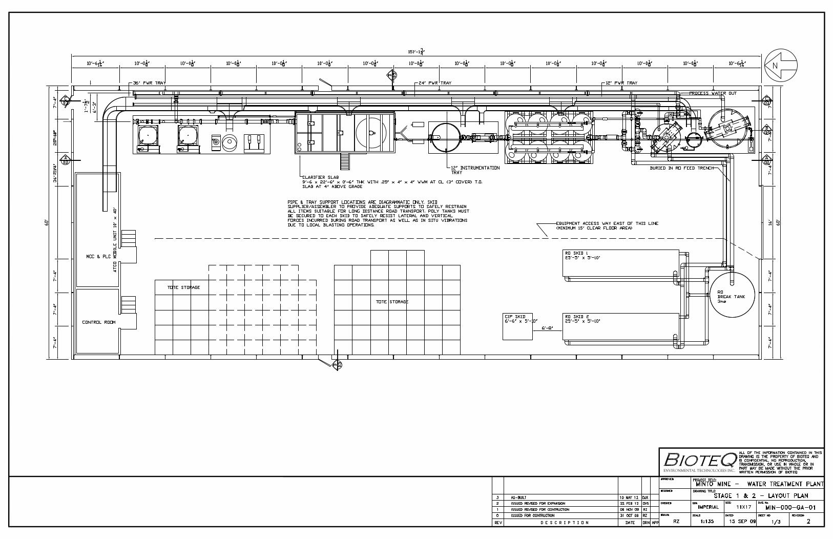
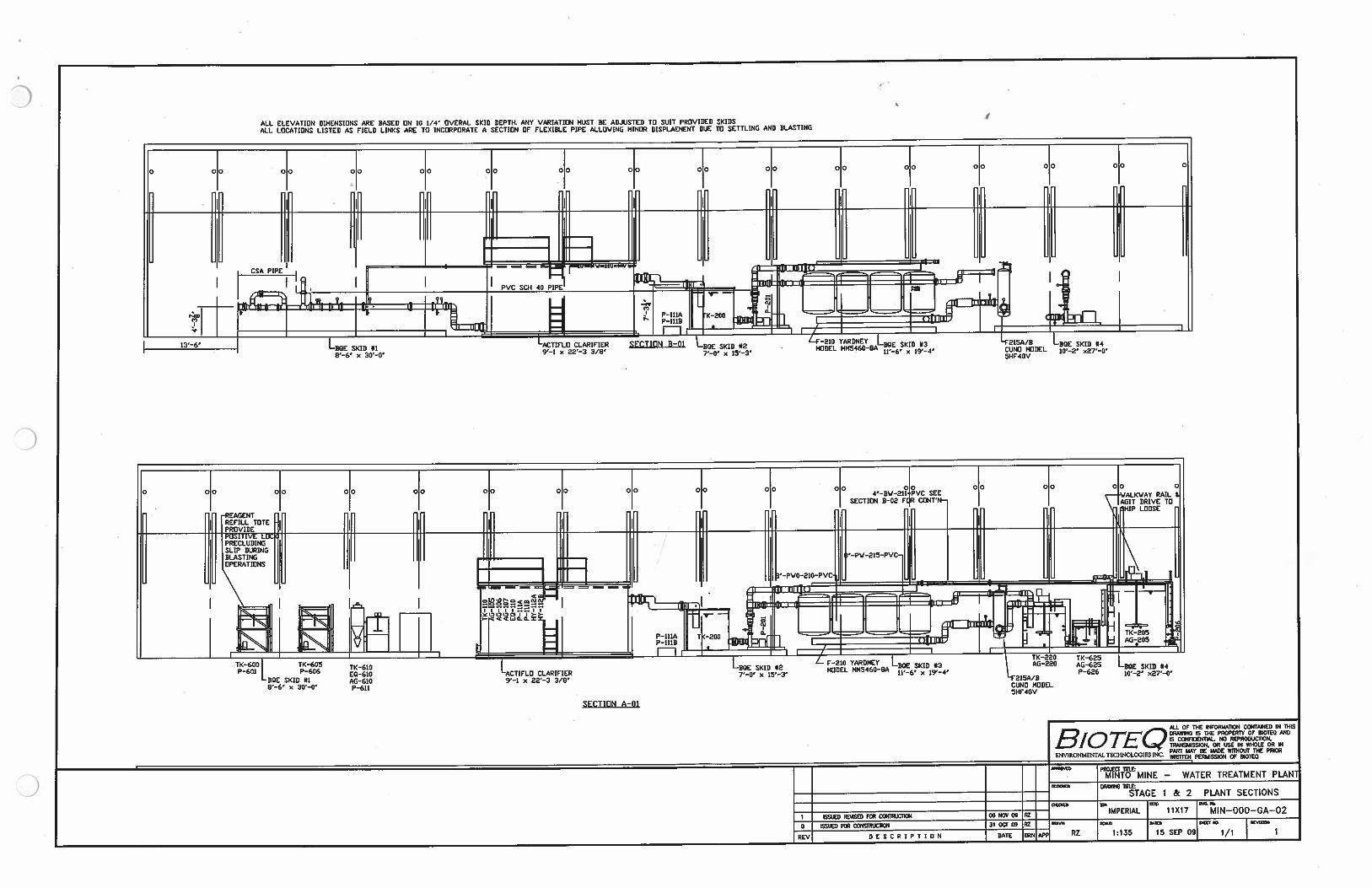
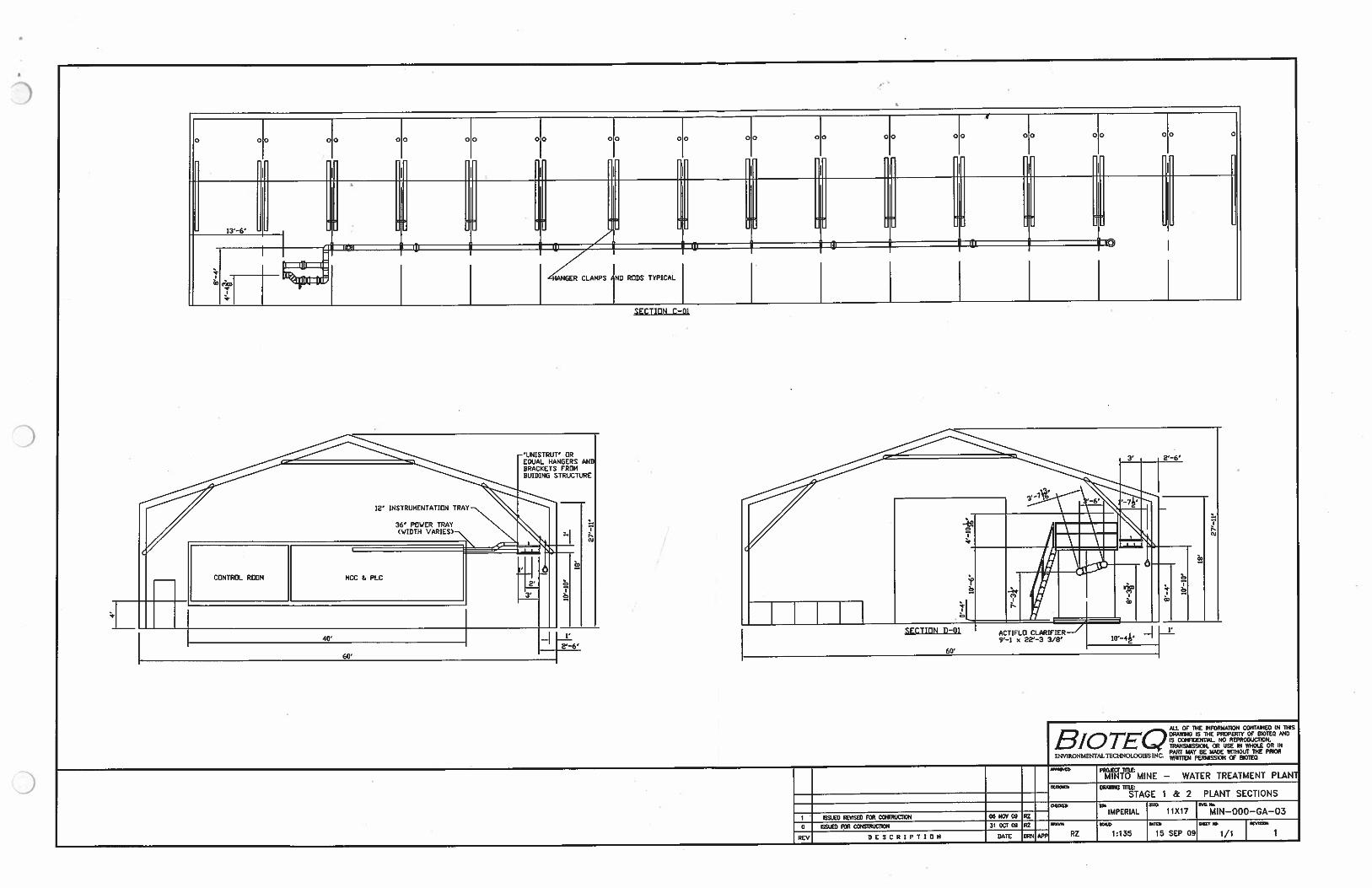
Water from the Main Pit has been treated through the Water Treatment Plant for discharge to the
receiving environment during the freshet periods in 2012, 2013 and in 2014. Treatment of water from
the Area 2 pit is also likely to occur as that pit becomes a water and tailings management facility.
The Water Treatment Plant accepts feed water from the Main Pit or WSP and discharges treated water
to the Main Pit, WSP or Minto Creek. Sludge and the reverse osmosis plant concentrate stream
produced in the treatment process are pumped to the Main Pit. The first stage of the water treatment
plant at Minto was constructed in 2010. The water treatment process included a ballasted lamella
clarifier unit (Actiflo®) system for removal of TSS, total metals and dissolved copper.
Minto Explorations Ltd. – Minto Mine 2014 Mill Development and Operations Plan
June 2014 6
In 2012, two reverse osmosis (RO) trains were added to the treatment process downstream of the
existing clarification and filtration units to treat nitrate and selenium, based on water quality limits
received in the Water Use Licence Amendment 7. Treated effluent from the RO units may also be
amended, when necessary, with sodium bicarbonate to adjust the pH and add salinity and alkalinity.
The RO process removes 95–99% of all constituents in the feed water. The feed water for the RO unit is
the effluent from clarification and filtration unit, which is operated as a pre-treatment step. The RO unit
produces a clean effluent stream that consists of approximately 75% of the feed water (the RO
permeate). The by-product of the process is a brine stream, which consists of about 25% of the feed
water and 95–99% of constituent loadings. The brine stream is pumped to the Main Pit Tailings
Management Facility or will be pumped to the Area 2 Pit Tailings Management Facility. Because of this
brine by-product, RO cannot be considered a true water treatment process but is rather a process that
concentrates mine water into a smaller volume with higher constituent concentrations.
A schematic of the water treatment plant is provided in Appendix A. More detail about the water
management at the Minto mine is provided in the 2014 Minto Mine Water Management Plan.
3 Milling Methods
The Minto Mine process plant design incorporates standard crushing, grinding, flotation, and
dewatering circuits to produce a final copper concentrate product. Ore from the Phase V/VI deposits will
be processed through the process plant as it currently operates.
The process schematic for the current Minto process plant is shown in Figure 3-1.

Minto Explorations Ltd. Minto Mine
2014 Mill Development and Operations Plan
April 2014 7
Figure 3-1: Minto Mill General Flow Sheet with Slurry Tailings
Na2S
MIBC addition point
(Dose = as required, ~20L/t)
PAX addition point
Sampling Point
Knelson Concentrate
Rougher Scavanger
Cleaner
Recleaner
Ball Mill 1 Ball Mill 2
Concentrate Thickener
Larox
Concentrates
Process Water
Tailings Thickener
Minto Pit
Process water
SAG
Recleaner
Concentrate Thickener
SAGSAGPhase 1 cyclones
Phase 2 cyclones
Pump Box
O/F tank
5g/t
1g/t
10g/t
20g/t
Apron Feeder
Knelson
100 g/t
100 g/t
Minto Explorations Ltd. Minto Mine
2014 Mill Development and Operations Plan
June 2014 8
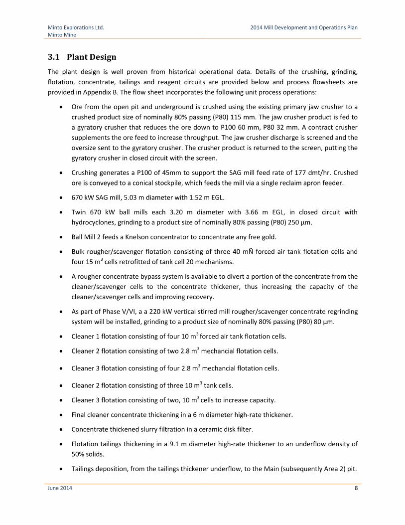
3.1 Plant Design
The plant design is well proven from historical operational data. Details of the crushing, grinding,
flotation, concentrate, tailings and reagent circuits are provided below and process flowsheets are
provided in Appendix B. The flow sheet incorporates the following unit process operations:
Ore from the open pit and underground is crushed using the existing primary jaw crusher to a
crushed product size of nominally 80% passing (P80) 115 mm. The jaw crusher product is fed to
a gyratory crusher that reduces the ore down to P100 60 mm, P80 32 mm. A contract crusher
supplements the ore feed to increase throughput. The jaw crusher discharge is screened and the
oversize sent to the gyratory crusher. The crusher product is returned to the screen, putting the
gyratory crusher in closed circuit with the screen.
Crushing generates a P100 of 45mm to support the SAG mill feed rate of 177 dmt/hr. Crushed
ore is conveyed to a conical stockpile, which feeds the mill via a single reclaim apron feeder.
670 kW SAG mill, 5.03 m diameter with 1.52 m EGL.
Twin 670 kW ball mills each 3.20 m diameter with 3.66 m EGL, in closed circuit with
hydrocyclones, grinding to a product size of nominally 80% passing (P80) 250 μm.
Ball Mill 2 feeds a Knelson concentrator to concentrate any free gold.
Bulk rougher/scavenger flotation consisting of three 40 mÑ forced air tank flotation cells and
four 15 m3 cells retrofitted of tank cell 20 mechanisms.
A rougher concentrate bypass system is available to divert a portion of the concentrate from the
cleaner/scavenger cells to the concentrate thickener, thus increasing the capacity of the
cleaner/scavenger cells and improving recovery.
As part of Phase V/VI, a a 220 kW vertical stirred mill rougher/scavenger concentrate regrinding
system will be installed, grinding to a product size of nominally 80% passing (P80) 80 μm.
Cleaner 1 flotation consisting of four 10 m3 forced air tank flotation cells.
Cleaner 2 flotation consisting of two 2.8 m3 mechancial flotation cells.
Cleaner 3 flotation consisting of four 2.8 m3 mechancial flotation cells.
Cleaner 2 flotation consisting of three 10 m3 tank cells.
Cleaner 3 flotation consisting of two, 10 m3 cells to increase capacity.
Final cleaner concentrate thickening in a 6 m diameter high-rate thickener.
Concentrate thickened slurry filtration in a ceramic disk filter.
Flotation tailings thickening in a 9.1 m diameter high-rate thickener to an underflow density of
50% solids.
Tailings deposition, from the tailings thickener underflow, to the Main (subsequently Area 2) pit.
Minto Explorations Ltd. Minto Mine
2014 Mill Development and Operations Plan
June 2014 9
Plant reagent preparation and distribution systems.
Raw process plant water supply from the existing site water storage facility reticulated
throughout the plant as required.
Process water dam and distribution system for reticulation of process water throughout the
plant as required per the existing facilities. Process water is supplied from water reclaimed from
tailings deposition in the Minto Main pit, from process operations and site run‐off with raw
water used as make‐up water as required.
Plant, instrument and flotation air services and associated infrastructure.
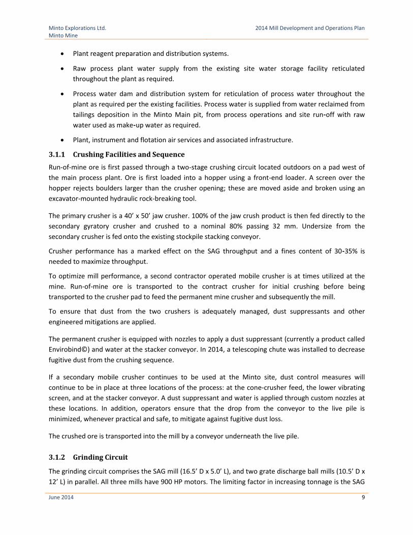
3.1.1 Crushing Facilities and Sequence
Run-of-mine ore is first passed through a two-stage crushing circuit located outdoors on a pad west of
the main process plant. Ore is first loaded into a hopper using a front-end loader. A screen over the
hopper rejects boulders larger than the crusher opening; these are moved aside and broken using an
excavator-mounted hydraulic rock-breaking tool.
The primary crusher is a 40’ x 50’ jaw crusher. 100% of the jaw crush product is then fed directly to the
secondary gyratory crusher and crushed to a nominal 80% passing 32 mm. Undersize from the
secondary crusher is fed onto the existing stockpile stacking conveyor.
Crusher performance has a marked effect on the SAG throughput and a fines content of 30‐35% is
needed to maximize throughput.
To optimize mill performance, a second contractor operated mobile crusher is at times utilized at the
mine. Run-of-mine ore is transported to the contract crusher for initial crushing before being
transported to the crusher pad to feed the permanent mine crusher and subsequently the mill.
To ensure that dust from the two crushers is adequately managed, dust suppressants and other
engineered mitigations are applied.
The permanent crusher is equipped with nozzles to apply a dust suppressant (currently a product called
Envirobind©) and water at the stacker conveyor. In 2014, a telescoping chute was installed to decrease
fugitive dust from the crushing sequence.
If a secondary mobile crusher continues to be used at the Minto site, dust control measures will
continue to be in place at three locations of the process: at the cone‐crusher feed, the lower vibrating
screen, and at the stacker conveyor. A dust suppressant and water is applied through custom nozzles at
these locations. In addition, operators ensure that the drop from the conveyor to the live pile is
minimized, whenever practical and safe, to mitigate against fugitive dust loss.
The crushed ore is transported into the mill by a conveyor underneath the live pile.
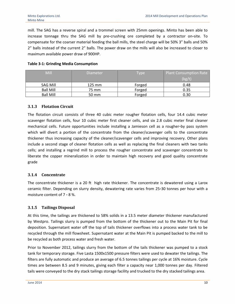
3.1.2 Grinding Circuit
The grinding circuit comprises the SAG mill (16.5’ D x 5.0’ L), and two grate discharge ball mills (10.5’ D x
12’ L) in parallel. All three mills have 900 HP motors. The limiting factor in increasing tonnage is the SAG
Minto Explorations Ltd. Minto Mine
2014 Mill Development and Operations Plan
June 2014 10
mill. The SAG has a reverse spiral and a trommel screen with 25mm openings. Minto has been able to
increase tonnage thru the SAG mill by pre‐crushing ore completed by a contractor on‐site. To
compensate for the coarser material feeding the ball mills, the steel charge will be 50% 3” balls and 50%
2” balls instead of the current 2” balls. The power draw on the mills will also be increased to closer to
maximum available power draw of 900HP.
Table 3-1: Grinding Media Consumption
Mill Diameter Type Plant Consumption Rate
(kg/t)
SAG Mill 125 mm Forged 0.48 Ball Mill 75 mm Forged 0.35 Ball Mill 50 mm Forged 0.30
3.1.3 Flotation Circuit
The flotation circuit consists of three 40 cubic meter rougher flotation cells, four 14.4 cubic meter
scavenger flotation cells, four 10 cubic meter first cleaner cells, and six 2.8 cubic meter final cleaner
mechanical cells. Future opportunities include installing a Jamieson cell as a rougher‐by pass system
which will divert a portion of the concentrate from the cleaner/scavenger cells to the concentrate
thickener thus increasing capacity of the cleaner/scavenger cells and improving recovery. Other plans
include a second stage of cleaner flotation cells as well as replacing the final cleaners with two tanks
cells; and installing a regrind mill to process the rougher concentrate and scavenger concentrate to
liberate the copper mineralization in order to maintain high recovery and good quality concentrate
grade
3.1.4 Concentrate
The concentrate thickener is a 20 ft high rate thickener. The concentrate is dewatered using a Larox
ceramic filter. Depending on slurry density, dewatering rate varies from 25‐30 tonnes per hour with a
moisture content of 7 ‐ 8 %.
3.1.5 Tailings Disposal
At this time, the tailings are thickened to 58% solids in a 13.5 meter diameter thickener manufactured
by Westpro. Tailings slurry is pumped from the bottom of the thickener out to the Main Pit for final
deposition. Supernatant water off the top of tails thickener overflows into a process water tank to be
recycled through the mill flowsheet. Supernatant water at the Main Pit is pumped backed to the mill to
be recycled as both process water and fresh water.
Prior to November 2012, tailings slurry from the bottom of the tails thickener was pumped to a stock
tank for temporary storage. Five Lasta 1500x1500 pressure filters were used to dewater the tailings. The
filters are fully automatic and produce an average of 6.5 tonnes tailings per cycle at 16% moisture. Cycle
times are between 8.5 and 9 minutes, giving each filter a capacity near 1,000 tonnes per day. Filtered
tails were conveyed to the dry stack tailings storage facility and trucked to the dry stacked tailings area.
Minto Explorations Ltd. Minto Mine
2014 Mill Development and Operations Plan
June 2014 11
Minto discontinued dry stacking of tailings in 2012 and has since followed an in‐pit tailings deposition
plan.
While Minto does not intend to dry stack tailings as part of the Phase V/VI plan, the facilities will remain
in place for consideration in future tailings disposal options.
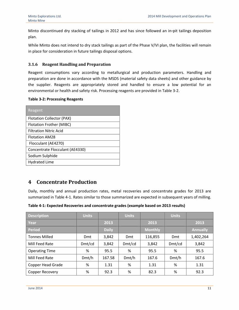
3.1.6 Reagent Handling and Preparation
Reagent consumptions vary according to metallurgical and production parameters. Handling and
preparation are done in accordance with the MSDS (material safety data sheets) and other guidance by
the supplier. Reagents are appropriately stored and handled to ensure a low potential for an
environmental or health and safety risk. Processing reagents are provided in Table 3-2.
Table 3-2: Processing Reagents
Reagent
Flotation Collector (PAX)
Flotation Frother (MIBC)
Filtration Nitric Acid
Flotation AM28
Flocculant (AE4270)
Concentrate Flocculant (AE4330)
Sodium Sulphide
Hydrated Lime
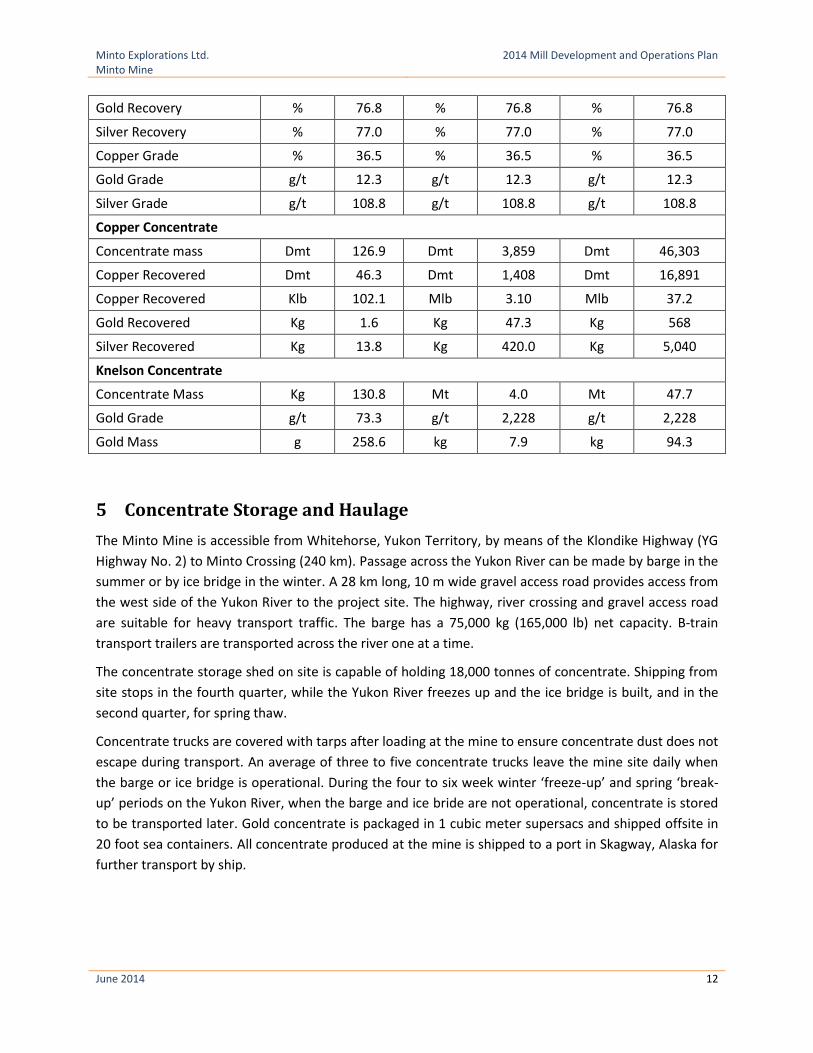
4 Concentrate Production
Daily, monthly and annual production rates, metal recoveries and concentrate grades for 2013 are
summarized in Table 4-1. Rates similar to those summarized are expected in subsequent years of milling.
Table 4-1: Expected Recoveries and concentrate grades (example based on 2013 results)
Description Units Units Units
Year 2013 2013 2013
Period Daily Monthly Annually
Tonnes Milled Dmt 3,842 Dmt 116,855 Dmt 1,402,264
Mill Feed Rate Dmt/cd 3,842 Dmt/cd 3,842 Dmt/cd 3,842
Operating Time % 95.5 % 95.5 % 95.5
Mill Feed Rate Dmt/h 167.58 Dmt/h 167.6 Dmt/h 167.6
Copper Head Grade % 1.31 % 1.31 % 1.31
Copper Recovery % 92.3 % 82.3 % 92.3
Minto Explorations Ltd. Minto Mine
2014 Mill Development and Operations Plan
June 2014 12
Gold Recovery % 76.8 % 76.8 % 76.8
Silver Recovery % 77.0 % 77.0 % 77.0
Copper Grade % 36.5 % 36.5 % 36.5
Gold Grade g/t 12.3 g/t 12.3 g/t 12.3
Silver Grade g/t 108.8 g/t 108.8 g/t 108.8
Copper Concentrate
Concentrate mass Dmt 126.9 Dmt 3,859 Dmt 46,303
Copper Recovered Dmt 46.3 Dmt 1,408 Dmt 16,891
Copper Recovered Klb 102.1 Mlb 3.10 Mlb 37.2
Gold Recovered Kg 1.6 Kg 47.3 Kg 568
Silver Recovered Kg 13.8 Kg 420.0 Kg 5,040
Knelson Concentrate
Concentrate Mass Kg 130.8 Mt 4.0 Mt 47.7
Gold Grade g/t 73.3 g/t 2,228 g/t 2,228
Gold Mass g 258.6 kg 7.9 kg 94.3
5 Concentrate Storage and Haulage
The Minto Mine is accessible from Whitehorse, Yukon Territory, by means of the Klondike Highway (YG
Highway No. 2) to Minto Crossing (240 km). Passage across the Yukon River can be made by barge in the
summer or by ice bridge in the winter. A 28 km long, 10 m wide gravel access road provides access from
the west side of the Yukon River to the project site. The highway, river crossing and gravel access road
are suitable for heavy transport traffic. The barge has a 75,000 kg (165,000 lb) net capacity. B‐train
transport trailers are transported across the river one at a time.
The concentrate storage shed on site is capable of holding 18,000 tonnes of concentrate. Shipping from
site stops in the fourth quarter, while the Yukon River freezes up and the ice bridge is built, and in the
second quarter, for spring thaw.
Concentrate trucks are covered with tarps after loading at the mine to ensure concentrate dust does not
escape during transport. An average of three to five concentrate trucks leave the mine site daily when
the barge or ice bridge is operational. During the four to six week winter ‘freeze-up’ and spring ‘break-
up’ periods on the Yukon River, when the barge and ice bride are not operational, concentrate is stored
to be transported later. Gold concentrate is packaged in 1 cubic meter supersacs and shipped offsite in
20 foot sea containers. All concentrate produced at the mine is shipped to a port in Skagway, Alaska for
further transport by ship.

Minto Explorations Ltd. Minto Mine
2014 Mill Development and Operations Plan
June 2014 13
6 References
Minto Explorations Ltd. . (2011). Decommissioning and Reclamation Plan. Minto Mine.
Minto Explorations Ltd. (2014). Minto Mine Water Management Pan.
Minto Explorations Ltd. (2014). Tailings Management Plan.
Yukon Government. (2013, August). Plan Requirement Guidance for Quartz Mining Projects. From
http://www.yukonwaterboard.ca/forms/quartz/Plan%20Requirement%20Guideline%20for%20Quartz%
20Mining%20Projects%20-%20August%202013-kh.pdf
Yukon Government. (2003, March 25). Quartz Mining Land Use Regulations O.I.C. 2003/64. Whitehorse,
Yukon.

Minto Explorations Ltd. Minto Mine
2014 Mill Development and Operations Plan
June 2014
Appendix A
Mill Facility Schematics (Water Storage Pond, Water Treatment Plant)

Minto Explorations Ltd. Minto Mine
2014 Mill Development and Operations Plan
June 2014
Appendix B
Crushing, Grinding, Flotation, Concentrate, Tailings and Reagent Process Flowsheets


