
• Complete Educational Jet Propulsion Power System
• Suitable for Secondary, University, Technical and Military Education and Training
• Purpose Built Gas Turbine Engine Designed and Manufactured to Aerospace Standards
• Integrated Test Cell ~ Requires No Facilities Modification
• All Key Engine Stations Fully Instrumented for Temperature and Pressure Measurement
• Most Stable and Reliable Operation of any Engine in Size and Thrust Class
• Fully Instrumented Operator Control Panel Featuring OneTouchTM Automatic Start
• DigiDAQTM Data Acquisition System Utilizing USB Technology
• User Configurable Real Time Computer Data Display
• Designed to Meet ABET Criterion 4 and 6 Objectives
• Supplied with a Comprehensive Operator’s Manual, Checklists and Safety Instructions
• Industry Leading Warranty with Unsurpassed End-User Support
• Designed and Manufactured in the USA
MiniLabTM
Gas Turbine Power System
Product Summary
CREATING EDUCATIONAL LABORATORY EQUIPMENT FOR TOMORROW’S ENGINEER
A fully integrated jet propulsion
laboratory ideally suited for
both introductory and
advanced study of
thermodynamic
and operating
principles of
gas turbine
power plants.

CREATING EDUCATIONAL LABORATORY EQUIPMENT FOR TOMORROW’S ENGINEER
MiniLabTM
Gas Turbine Power System
Description
A complete gas turbine power plant designed for engineering, technical and military education as well as advanced research and study. The core
gas-generator is representative of all major gas turbine types and permits ready textbook direct analysis of air equivalent Brayton and Gas
Turbine cycles. Students are able to apply fluids, thermodynamic, combustion and gas turbine theory to the operation of an actual engine.
Laboratory experience gained with the MiniLab™ is directly applicable to aero and marine turbine propulsion and industrial gas turbine applications.
The SR-30 Turbo-Jet engine is designed and manufactured by Turbine Technologies, LTD specifically for the MiniLab™ Gas Turbine Power
System. The compact engine features a centrifugal flow compressor, reverse flow annular combustor and an axial flow turbine stage. The SR-30
follows the fundamental gas turbine cycle: Ambient air enters the engine through the bell shaped inlet. The air is then compressed, diffused and
directed into the combustor can. Kerosene based fuel, introduced via six high-pressure atomization nozzles, is mixed with the compressed air
and ignited. Heated combustion gas expands and accelerates through the vane guide ring causing the turbine to rotate. Useful work is extracted
from this rotation as the turbine powers the compressor. The combustion gases are further accelerated through the thrust nozzle where the
remaining heat energy is converted to kinetic energy in the form of jet thrust. The ejected gas returns to ambient atmospheric conditions thereby
completing the thermodynamic cycle.
For safety and performance reasons, no off-the-shelf, former military or surplus components are used in any portion of the engine. All components
are manufactured in-house to exacting specifications. Electronic controlled vacuum investment casting insures void and impurity free components.
Computer numerically controlled machine centers maximize finished part accuracy. Individual component materials are selected based upon
desired mechanical properties, durability and longevity. Combustor components and the vane guide ring utilize Inconel® 718 alloy. The integral
bladed disk turbine wheel is manufactured from CMR 247 Super Alloy. All material is fully traceable and verified to possess the desired properties
specific to the application. The completed engine undergoes rigorous final operational testing and inspection. Purpose built from the start, the
SR-30 requires no questionable modifications prior to integration into the MiniLab™ Gas Turbine Power System.
The MiniLab™ cabinetry is composed of a rigid steel chassis mounted on rolling castors for portability and ease of storage, requiring no permanent
facility modifications or additions. The SR-30 engine is securely mounted within the cabinet behind protective transparent polycarbonate shields
affording the operator and observers clear, unimpeded viewing of the engine during operation. All engine accessories including fuel and oil
pumps are located in the lower portion of the cabinet. No dedicated engine accessory drive is required, thereby eliminating the distraction of
non-essential engine loading considerations in thermodynamic and performance analysis. Safe and reliable air starting provides for consistent
and easy engine operation without the need for additional electric starters, complicated couplings, heavy cabling, high amperage current or
auxiliary batteries. All fuel atomization is accomplished within the fuel control unit and adjacent nozzles. No gaseous fuels of any type are
required for starting. A wide range of kerosene based or diesel blended fuels may be used without the need for any fuel preheating or conditioning.
A single button initiates automatic engine start. System parameters are monitored during all phases of engine operation by an electronic
engine control unit. Any out-of-limit condition results in the safe shutdown of the engine. Fuel and oil levels are monitored continuously
thereby eliminating the potential for damaged pumps due to dry operation. Engine speed is fully controllable. A liquid crystal display panel
alerts the operator to any system faults. Total run time and cycle counts are digitally recorded. A single button, prominently marked and readily
located safely shuts the system down.
Industrial grade sensors measure all key engine station parameters as
well as overall system variables for real time display on the provided
computer. Direct engine thrust is accurately measured through a
pivoting bearing arrangement utilizing a calibrated load cell, eliminating
problems inherent to linear bearings with critical alignment requirements.
A USB connected digital data acquisition system is fully integrated and
precalibrated. User configurable software allows the creation of custom
data displays without the need for programming. Data can be recorded
for playback or follow-on analysis. The full range of sensors allows
calculations of fuel flow, thrust and pressure ratio to be compared
directly to measured values.
Design, technical and manufacturing information and specifications are
available for specific teaching and research requirements. Actual engine
components and system parts are optionally available for use as teaching
and training aids. As the original engine manufacturer, complete spares
availability is guaranteed. A free, two year warranty is provided on the
entire MiniLab™ system including the SR-30 engine. Additional service
and support is available as necessary. On site operator training is
available at additional cost.
A comprehensive Operator’s Manual details all aspects of system
operation. Summary operating checklists allow rapid mastery of
MiniLab™ Gas Turbine Power System operation. Safety instructions
address all operating conditions.
CREATING EDUCATIONAL LABORATORY EQUIPMENT FOR TOMORROW’S ENGINEER
MiniLabTM
Gas Turbine Power System
Experimental Opportunities
Experimental and research opportunities include scientific, engineering, thermodynamic and environmental investigations. With a wide array of
sensors, experiments relating to secondary education physics and chemistry through graduate level fuels and combustion research are readily
performed. Standard courses in engineering thermodynamics and fluid mechanics benefit from textbook direct examples conducted and
measured in real time. The limitations of theoretical models and the variability of experimental technique can be experienced first hand. In
addition to academics, the MiniLab™ is ideally suited for general gas turbine familiarization and jet engine operational training for aviation and
military professionals.
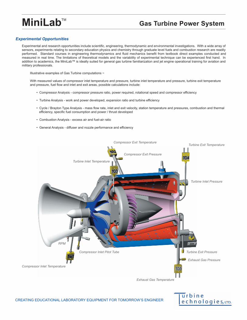
Illustrative examples of Gas Turbine computations ~
With measured values of compressor inlet temperature and pressure, turbine inlet temperature and pressure, turbine exit temperature
and pressure, fuel flow and inlet and exit areas, possible calculations include:
• Compressor Analysis - compressor pressure ratio, power required, rotational speed and compressor efficiency
• Turbine Analysis - work and power developed, expansion ratio and turbine efficiency
• Cycle / Brayton Type Analysis - mass flow rate, inlet and exit velocity, station temperature and pressures, combustion and thermal
efficiency, specific fuel consumption and power / thrust developed
• Combustion Analysis - excess air and fuel-air ratio
• General Analysis - diffuser and nozzle performance and efficiency
Compressor Exit Temperature
Compressor Exit Pressure
Turbine Inlet Temperature
Turbine Exit Temperature
Exhaust Gas Temperature
Compressor Inlet Temperature
Turbine Exit Pressure
Exhaust Gas Pressure
Compressor Inlet Pitot Tube
Turbine Inlet Pressure
RPM

Turbine Technologies Ltd. 410 Phillips St. Chetek, WI U.S.A • Ph: 715-924-4876 Fax: 715-924-2436 www.turbinetechnologies.com [email protected] v1.7 © 2007
CREATING EDUCATIONAL LABORATORY EQUIPMENT FOR TOMORROW’S ENGINEER
MiniLabTM
Gas Turbine Power System
Details Purchase Specifications
•
•
•
•
•
•
•
•
•
•
•
•
•
•
•
•
•
•
•
•
•
•
Dimensions
MiniLab™: 40 W x 42 D x 62 H inches (102 x 107 x 158 cm)
As Shipped: 48 W x 54 D x 70 H inches (122 x 137 x 178 cm)
Weight
MiniLab™: 460 lbs (208 kg)
As Shipped: 614 lbs (276 kg)
Instrumentation
Digital: High Speed Data Acquisition System
Data Acquisition Software with Configurable Data Output
Windows® XP Computer for On-Screen Data Display
Single Cable DigiDAQ™ USB to PC Connection
20 Analog IN - 16 Digital IN/OUT - 4 Frequency/Pulse IN
Sensors (Preinstalled and Calibrated)
• Compressor Inlet Temperature and Pressure (T1/P1)
• Compressor Exit Temperature and Pressure (T02/P02)
• Turbine Stage Inlet Temperature and Pressure (T03/P3)
• Turbine Stage Exit Temperature and Pressure (T04/P04)
• Thrust Nozzle Exit Temperature and Pressure (T05/P05)
• Fuel Flow
• Thrust
• Engine Rotational Speed (RPM)
Digital and Analog: As provided on the Operator Control Panel
• Digital Turbine Inlet Temperature (TIT)
• Digital Exhaust Gas Temperature (EGT)
• Digital Engine Rotational Speed (RPM)
• Analog Oil Pressure
• Analog Engine Pressure
• Analog Air Start Pressure
Operator Panel Controls
Master Switch, Keyed - Secured control of equipment usage
Green Start Button, Push- Initiates Engine Start, Multiple Functions
Red Stop Button, Push- Initiates Engine Shutdown, Multiple Functions
T-Handled Power Lever - Controls Engine RPM
Integral LCD Display - Real Time System Status
Operating Conditions / Limitations
Design Maximum Thrust: 40 lbf (178 N)
Approved Fuels: Jet A, A-1, B; JP-4, 5, 8;
Kerosene, Diesel, Fuel Oil #1 or #2
Exhaust Gas Temperature: 1328˚ F (720˚ C)
Mass Flow: 1.1 lbs/s (0.5 kg/s)
Ignition System: Air gap, high voltage capacitor discharge
type hermetically sealed ignition coil and
igniter plug
Compressor Type: Single Stage Centrifugal (Radial Outflow)
Turbine Type: Single Stage Axial Flow
Design Maximum RPM: 87,000
Engine Mount: Pivot bearing support allowing direct thrust
to be obtained by a load cell
Engine Compression Ratio: 3.4
Engine Pressure Ratio: 30.0
Specific Fuel Consumption: 1.2
Approved Oils: MIL-PRF-23699F-STD
Engine Diameter: 6.8 inches (17 cm)
Engine Length: 10.8 inches (27 cm)
Operating Requirements
Typical Laboratory Setting
Power: 120V single-phase 60Hz (220V upon request)
Air: Typically available 120PSI shop air
A complete gas-turbine power system to
consist of an engine designed and
manufactured for engineering education.
Engine must utilize a centrifugal flow com-
pressor, reverse flow annular combustor and
an axial flow turbine stage.
Engine to be of current manufacture and
consisting of all new components.
All engine components either vacuum investment
cast or precision CNC machined.
All high-heat components manufactured
from 17-4 ph stainless steel, Inconel® 718
or CMR 247 Super Alloy.
Traceable and verifiable material to be used
throughout engine.
All elements comprising the system to be
contained in a rigid steel chassis mounted
on rolling castors.
All system metal surfaces to be stainless
steel, anodized or powder coated to promote
durability and wear resistance.
Complete system not to require any permanent
facility modifications or additions.
Engine situated behind transparent protective
shields allowing clear view during operation.
Operator capable of manual control through-
out entire range of operation.
Operator panel to consist of digital TIT, EGT,
and RPM indicators, analog oil pressure, en-
gine pressure ratio, fuel pressure and air
pressure gauges, keyed master, green start,
red stop and T-handled power control lever.
System to be equipped with calibrated
transducers and thermocouples capable of
measuring compressor inlet, compressor exit,
turbine stage inlet, turbine stage exit and
thrust nozzle exit temperature and pressures,
fuel flow, thrust and engine compressor /
turbine rotational speed.
Engine thrust to be measured by a load cell
permitting direct indication of thrust value.
To be supplied with a USB based digital data
acquisition system complete with computer
and user configurable data acquisition software
capable of measuring and recording analog,
digital and frequency signals.
Fully automatic engine start and operational
health monitoring system provided with
LCD status readout and cumulative run-
time and cycle count.
Representative engine components and
technical data optionally available for
teaching use and training aids.
Manufacturer to guarantee spares availability
and provide technical support services for
core engine and power system.
Provided with a comprehensive Operator’s
Manual.
Provided with summary operating checklist
for all operating conditions.
Provided with safety instruction to address
all operating conditions.
To be covered by a free two year warranty.


