
Applications & Tools
Answers for industry.
Cover
Master Slave Communication via a CM PtP using the Modbus RTU Protocol
S7-1500 CM PtP RS422/485 HF, ET 200SP CM PtP
Application Description March 2013

2 Master-Slave Communication with Modbus RTU
1.0, Entry ID: 68202723
Cop
yrig
ht
Sie
men
s A
G 2
013
All
right
s re
serv
ed
Siemens Industry Online Support This article is taken from the Siemens Industry Online Support. The following link takes you directly to the download page of this document: http://support.automation.siemens.com/WW/view/en/68202723 Caution: The functions and solutions described in this entry are mainly limited to the realization of the automation task. In addition, please note that suitable security measures in compliance with the applicable Industrial Security standards must be taken, if your system is interconnected with other parts of the plant, the company’s network or the Internet. Further information can be found under the Item-ID 50203404. http://support.automation.siemens.com/WW/view/en/50203404

Master-Slave Communication with Modbus RTU 1.0, Entry ID: 68202723 3
Cop
yrig
ht
Sie
men
s A
G 2
013
All
right
s re
serv
ed
s
SIMATIC Master Slave Communication with Modbus RTU
Task 1
Solution 2
Description of the Modbus RTU Protocol
3 Description of the STEP 7 program
4 Configuration and Settings
5 Starting Up the Application
6
Operating the Application 7
Literature 8
History 9

Warranty and Liability
4 Master-Slave Communication with Modbus RTU
1.0, Entry ID: 68202723
Cop
yrig
ht
Sie
men
s A
G 2
013
All
right
s re
serv
ed
Warranty and Liability
Note The Application Examples are not binding and do not claim to be complete regarding the circuits shown, equipping and any eventuality. The application examples do not represent customer-specific solutions. You are responsible for ensuring that the described products are used correctly. These Application Examples do not relieve you of your responsibility to use safe practices in application, installation, operation and maintenance. When using these Application Examples, you recognize that we cannot be made liable for any damage/claims beyond the liability clause described. We reserve the right to make changes to these Application Examples at any time and without prior notice. If there are any deviations between the recommendations provided in this application example and other Siemens publications – e.g. catalogs – the contents of the other documents have priority.
We do not accept any liability for the information contained in this document. Any claims against us – based on whatever legal reason – resulting from the use of the examples, information, programs, engineering and performance data etc., described in this Application Example shall be excluded. Such an exclusion shall not apply in the case of mandatory liability, e.g. under the German Product Liability Act (“Produkthaftungsgesetz”), in case of intent, gross negligence, or injury of life, body or health, guarantee for the quality of a product, fraudulent concealment of a deficiency or breach of a condition which goes to the root of the contract (“wesentliche Vertragspflichten”). The damages for a breach of a substantial contractual obligation are, however, limited to the foreseeable damage, typical for the type of contract, except in the event of intent or gross negligence or injury to life, body or health. The above provisions do not imply a change of the burden of proof to your detriment. Any form of duplication or distribution of these Application Examples or excerpts hereof is prohibited without the expressed consent of Siemens Industry Sector.

Table of Contents
Master-Slave Communication with Modbus RTU 1.0, Entry ID: 68202723 5
Cop
yrig
ht
Sie
men
s A
G 2
013
All
right
s re
serv
ed
Table of Contents Caution: .................................................................................................................... 2 Warranty and Liability .............................................................................................. 4 Table of Contents ..................................................................................................... 5 1 Task................................................................................................................. 6 2 Solution........................................................................................................... 7
2.1 Solution overview .............................................................................. 7 2.2 Hardware and software components used ......................................... 9
3 Description of the Modbus RTU Protocol.................................................... 11
3.1 Operation of ModbusRTU ................................................................ 11 3.2 Configuring in STEP 7 V12 .............................................................. 13
4 Description of the STEP 7 program ............................................................. 15 4.1 Overview ......................................................................................... 15 4.2 Operation of the FB Master_Modbus (FB775) .................................. 17 4.2.1 States and call of the FB Master_Modbus ........................................ 17 4.2.2 "INIT" state ...................................................................................... 19 4.2.3 "Config_Modbus" state .................................................................... 19 4.2.4 "datatransfer" state .......................................................................... 21 4.2.5 UDT Data_for_Master ...................................................................... 23 4.3 Operation of the FB Slave_Modbus (FB776) .................................... 24 4.3.1 Parameter ....................................................................................... 24 4.3.2 Block details .................................................................................... 25 4.3.3 UDT Data_Slave.............................................................................. 27 4.4 DB Comm_Data .............................................................................. 28
5 Configuration and Settings .......................................................................... 29
5.1 Changing the communication settings .............................................. 29 5.2 Changing the existing communication jobs ....................................... 30 5.3 Adding another slave or communication job ..................................... 30 5.4 Adjusting the receive buffer.............................................................. 33
6 Starting Up the Application .......................................................................... 34
6.1 Setup of the hardware ..................................................................... 34 6.2 Configuring the hardware ................................................................. 36 6.3 Opening and loading of the STEP 7 project ...................................... 37
7 Operating the Application ............................................................................ 38
7.1 Monitoring ....................................................................................... 38 7.2 Reading data from the Modbus slave to the Modbus master ............ 39
8 Literature ...................................................................................................... 40
Internet Links .................................................................................................. 40 9 History .......................................................................................................... 40

1 Task
6 Master-Slave Communication with Modbus RTU
1.0, Entry ID: 68202723
Cop
yrig
ht
Sie
men
s A
G 2
013
All
right
s re
serv
ed
1 Task Introduction
This application shows you how to use the Modbus RTU protocol of the CM PtPs in the SIMATIC S7-1500 and the distributed I/O system ET 200SP.
Overview of the automation task The figure below provides an overview of the automation task. Figure 1-1
S7-1500Automation system
Communica-tion interface
S7-1500Controller:
configuration,data storage
RS485
Modbus-Slaves
I/O
Description of the automation task The application is to cover the following requirements: Demonstrate the use with the CM PtP RS422/485 HF and the CM PtP of the
ET 200SP on a concrete application with Modbus RTU. encapsulated, flexible master/slave programming in an example.

2 Solution 2.1 Solution overview
Master-Slave Communication with Modbus RTU 1.0, Entry ID: 68202723 7
Cop
yrig
ht
Sie
men
s A
G 2
013
All
right
s re
serv
ed
2 Solution 2.1 Solution overview
Objective of this application This application shows you the configuration of a CM (communication module) PtP for the communication
with Modbus RTU. the flexible programming of a Modbus master for the communication with
several slaves. the programming of a Modbus slave for the communication with a master.
The precise functionality of the program is described in chapter 4.
Schematic layout The following figure gives a schematic overview of the most important components of the solution: Figure 2-1
STEP7 V12
Engineering station
RS485
ET 200SP
CM PtP1(RTU slave)
CM PtP 2(RTU slave)
CM PtP(RTU master)
S7-1500 CPU:Program forModbus master & Modbus slaves

2 Solution 2.1 Solution overview
8 Master-Slave Communication with Modbus RTU
1.0, Entry ID: 68202723
Cop
yrig
ht
Sie
men
s A
G 2
013
All
right
s re
serv
ed
Core topics of this application The following points are presented in this application: Basics on Modbus RTU protocol Configuring the hardware environment Configuring the serial interfaces for the Modbus RTU protocol Programming the data read in the Modbus RTU master Programming the Modbus slave functionality in a SIMATIC S7 CPU
In the sample project the CM PtP RS422/485 HF alternately reads eight words of data as Modbus master from the two slaves (CM PtPs of the ET 200SP). The user program of the master and the slave is located in the S7-1500 CPU. Programming the Modbus master with the help of the FB Master_Modbus (FB776) and an instance data block (e.g. DB Master_Modbus_DB (DB775)) the DB Comm_Data (DB778)
– with the Param structure – with the PublicParam structure – with the Master_comm array – without the Slave array
For the output parameters the DB Output_Data (DB779) with the master structure
Programming the Modbus slave with the help of the FB Slave_Modbus (FB775) and an instance data block (e.g. DB Slave_Modbus_DB_1 (DB776)) the DB Comm_Data (DB778)
– with the Param structure – with the PublicParam structure – with the Slave array – without the Master_Comm array
For the output parameters the DB Output_Data (DB779) with the SlaveX structure
Advantages The present application offers you the advantage of fast access to the Modbus RTU subject in the SIMATIC S7-1500 environment. You get encapsulated functions for programming either a Modbus slave or a Modbus master.

2 Solution 2.2 Hardware and software components used
Master-Slave Communication with Modbus RTU 1.0, Entry ID: 68202723 9
Cop
yrig
ht
Sie
men
s A
G 2
013
All
right
s re
serv
ed
Validity Software versions from TIA Portal V12 SIMATIC S7-1500 CPUs CM PtP RS422/485 HF, CM PtP of the ET 200SP
Topics not covered by this application This application does not contain an introduction to the issue of SCL programming basics on TIA Portal V12.
Basic knowledge of these topics is assumed.
2.2 Hardware and software components used
This application was generated with the following components:
Hardware components Table 2-1
Component Qty. Ordering number Note PM 70W 120/230 AVC 1 6EP1332-4BA00 CPU 1516-3 PN/DP 1 6ES7516-3AN00-0AB0 Other CPUs from the
S7-1500 spectrum can also be used
CM PtP RS422/485 HF 1 6ES7541-1AB00-0AB0 The basic module (BA) is not Modbus RTU-capable
ET 200SP 1 6ES7155-6AU00-0BN0 CM PtP 2 6ES7137-6AA00-0BA0 BaseUnit 2 6ES7193-6BP00-0xA0 Server module 1 6ES7193-6PA00-0AA0 When ordering the
head station, already included.
Note If you are using a different hardware than the one in the sample project, you have to perform the respective changes in the hardware configuration!

2 Solution 2.2 Hardware and software components used
10 Master-Slave Communication with Modbus RTU
1.0, Entry ID: 68202723
Cop
yrig
ht
Sie
men
s A
G 2
013
All
right
s re
serv
ed
Standard software components Table 2-2
Component Qty. Order number Note STEP 7 V12 (TIA Portal V12)
1 6ES78221AE02-0YA5
Example files and projects The following list includes all files and projects used in this example. Table 2-3
Component Note 68202723_ S7-1500_ModbusRTU_CODE_V1d0.zap12
This zip file contains the archived STEP 7 project.
68202723_S7-1500_ModbusRTU_ DOKU_V1d0_en.pdf
This document.
For further documentation, for example, regarding the distributed I/O ET 200SP, please note chapter 8 Literature.

3 Description of the Modbus RTU Protocol 3.1 Operation of ModbusRTU
Master-Slave Communication with Modbus RTU 1.0, Entry ID: 68202723 11
Cop
yrig
ht
Sie
men
s A
G 2
013
All
right
s re
serv
ed
3 Description of the Modbus RTU Protocol 3.1 Operation of ModbusRTU
Overview Modbus RTU (Remote Terminal Unit) is a standard protocol for the serial communication between master and slave. Other protocols of the Modbus specification, such Modbus ASCII are not supported by the serial SIMATIC S7-1500 CMs.
Master-Slave relationship Modbus RTU uses a master/slave relationship in which the entire communication is based on one single master device, whilst the slaves only respond to the requests of the master. The master sends a request to a slave address and only the slave with this slave address replies to the command. Special case: when using the Modbus slave address 0, the CM PtP sends a broadcast telegram to all slaves (without receiving a slave reply).
Communication sequence The communication with Modbus RTU always occurs according to the following scheme: 1. The Modbus master sends a request to a Modbus slave in the network. 2. The slave replies with an answer telegram which includes the requested data
or which acknowledges the receipt of the request. 3. If the slave cannot process the request of the master, the slave replies with an
error telegram. The following table shows the structure of the telegram as an example, when data is to be read from one or several holding registers of the Modbus slave (Modbus Standard).
Table 3-1
Message frame
Byte 0 Byte 1 Byte 2 Byte 3 Byte 4 Byte 5 …
Request Slave address
Function code
Start address (from what holding register
is to be read)
Number of registers
Valid reply Slave address
Function code
Length Register data
Error message Slave address
0x83 Error code
---
The function code indicates the slave what function it is to execute. Table 3-2 lists the function codes that can be used with the CM PtPs: Table 3-2
Function code Function
01 Reading output bit 02 Reading input bit 03 Reading holding register

3 Description of the Modbus RTU Protocol 3.1 Operation of ModbusRTU
12 Master-Slave Communication with Modbus RTU
1.0, Entry ID: 68202723
Cop
yrig
ht
Sie
men
s A
G 2
013
All
right
s re
serv
ed
Function code Function
04 Reading input words 05 Writing one output bit 06 Writing one holding register 15 Writing one or several output bits 16 Writing one or several holding registers 11 Reading status word and event counter of the slave communication 08 Checking slave state via data diagnostic code/
resetting slave event counter via data diagnostic code
Performance data Number of devices on the bus Table 3-3
Modbus standard Number of addresses
Modbus RTU standard 247 Modbus RTU extended addressing 65535
For cable lengths over 50m a terminating resistor of approx. 330 Ohm has to be welded to the receiver side in order to have uninterrupted data traffic. Data length
Table 3-4
Instruction type Functions codes Maximum number per request
Bit instruction 1, 2, 5, 15 1992 bits Word instruction 3, 4, 6, 16 124 register (words)
The values specified are valid for a CM PtP RS422/485 HF and all serial communication processors of SIMATIC S7-1500.

3 Description of the Modbus RTU Protocol 3.2 Configuring in STEP 7 V12
Master-Slave Communication with Modbus RTU 1.0, Entry ID: 68202723 13
Cop
yrig
ht
Sie
men
s A
G 2
013
All
right
s re
serv
ed
3.2 Configuring in STEP 7 V12
Overview The TIA Portal enables the configuration of a Modbus RTU communication. This chapter shows you what settings you have to make in the hardware configuration. what properties the instructions for the Modbus RTU communication have.
Hardware configuration In the hardware configuration for the CM used, you only set that it is to communicate via the Modbus protocol. Table 3-5 shows the procedure: Table 3-5
No. Procedure Note
1. Open your project. Go to the device configuration and select your CM PtP.
2. Go to “Properties > RS422/485 interface
> Port configuration” and select the “Modbus” protocol. All other settings are made in the user program.

3 Description of the Modbus RTU Protocol 3.2 Configuring in STEP 7 V12
14 Master-Slave Communication with Modbus RTU
1.0, Entry ID: 68202723
Cop
yrig
ht
Sie
men
s A
G 2
013
All
right
s re
serv
ed
Communication blocks (instructions) for Modbus RTU The setting up of a communication module for the Modbus RTU protocol as well as its operation as master or slave is realized via the following instructions: Table 3-6
Instruction Description
Modbus_Comm_Load Configures a communication module for the communication via the Modbus RTU protocol. The instruction sets parameters such as the baud rate Parity Flow control …
Only after the successful configuration of the communication module, does a call of Modbus_Master or Modbus_Slave make sense.
Modbus_Master Communicates as Modbus master via a port that was configured with the Modbus_Comm_Load instruction. The function code of the Modbus RTU protocol (see Table 3-2) is specified via the following inputs: MODE DATA_ADDR DATA_LEN
An overview of what function code corresponds to what input parameters can found in the help for the Modbus_Master instruction in the TIA Portal.
Modbus_Slave With the Modbus_Slave instruction your program can communicate via a PtP port of a CM as Modbus slave. The Modbus_Slave realizes the communication with a Modbus master. The assignment of the parameters can be found in the help for Modbus_Slave instruction in the TIA Portal.
4 Description of the STEP 7 program 4.1 Overview
Master-Slave Communication with Modbus RTU 1.0, Entry ID: 68202723 15
Cop
yrig
ht
Sie
men
s A
G 2
013
All
right
s re
serv
ed
4 Description of the STEP 7 program 4.1 Overview
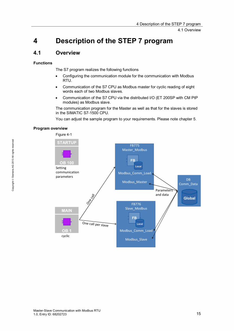
Functions The S7 program realizes the following functions Configuring the communication module for the communication with Modbus
RTU. Communication of the S7 CPU as Modbus master for cyclic reading of eight
words each of two Modbus slaves. Communication of the S7 CPU via the distributed I/O (ET 200SP with CM PtP
modules) as Modbus slave. The communication program for the Master as well as that for the slaves is stored in the SIMATIC S7-1500 CPU. You can adjust the sample program to your requirements. Please note chapter 5.
Program overview Figure 4-1
FB775Master_Modbus
Modbus_Comm_Load
Modbus_MasterDB
Comm_Data
FB776Slave_Modbus
Modbus_Comm_Load
Modbus_Slave
Parameters and data
Settingcommunicationparameters
One call per slave
One ca
ll
cyclic

4 Description of the STEP 7 program 4.1 Overview
16 Master-Slave Communication with Modbus RTU
1.0, Entry ID: 68202723
Cop
yrig
ht
Sie
men
s A
G 2
013
All
right
s re
serv
ed
Blocks and instructions The following blocks are used in the STEP 7-V12 project: Table 4-1
Element Symbolic name Description
OB1 Main Includes the main program. Calls the FB Master_Modbus and
the FB Slave_Modbus. Cyclically reads eight words via the
Modbus master alternately from the Modbus slaves.
Prog
ram
cal
l OB100 Startup The parameters for setting the
communication settings are preset with Modbus_Comm_Load.
Parameters for the master for the communication with the slaves are initialized.
Parameters for the slaves are initialized.
FB775 Master_Modbus Setting up a communication module as Modbus master for the communication with two Modbus slaves.
In-h
ouse
dev
elop
men
t
FB776 Slave_Modbus Per call: Setting up a communication module as Modbus slave for the communication with one Modbus master.
DB775 Master_Modbus_DB Instance DB of the FB Master_Modbus DB776 Slave_Modbus_DB_1 Instance DB of FB Slave_Modbus_DB DB777 Slave_Modbus_DB_2 Instance DB of FB Slave_Modbus_DB DB778 Comm_Data Includes
the parameters of the Modbus communication connection.
an array of Data_for_Master data type that provides the master with the required data for the communication with the slaves.
an array of Data_Slave data type that provides the slaves with the required data for communication.
DB779 Output_Data Includes the output parameters of the function blocks called in OB1
FB640 Modbus_Comm_Load Configuration of a communication module for the communication with the Modbus protocol.
Syst
em b
lock
s
FB641 Modbus_Master Communication of the module as Modbus master via the port that was configured with Modbus_Comm_Load.

4 Description of the STEP 7 program 4.2 Operation of the FB Master_Modbus (FB775)
Master-Slave Communication with Modbus RTU 1.0, Entry ID: 68202723 17
Cop
yrig
ht
Sie
men
s A
G 2
013
All
right
s re
serv
ed
4.2 Operation of the FB Master_Modbus (FB775)
4.2.1 States and call of the FB Master_Modbus
States FB Master_Modbus fulfils the following tasks: Initializing the communication parameters Configuring the master communication module Administering the communication jobs belonging to the Modbus slaves
The functionalities are realized in a simple sequence with the following states: Figure 4-2
New startINIT
initializes
configuresSending/receiving datafrom/to a slave A precise description of the individual states can be found in chapter 4.2.2.
Element Symbolic name Description
FB642 Modbus_Slave Communication of the module as Modbus slave via the port that was configured with Modbus_Comm_Load.
Syst
em b
lock
s
Other system blocks
For example: Receive_Config
Are called by the mentioned system blocks FB640-FB642.

4 Description of the STEP 7 program 4.2 Operation of the FB Master_Modbus (FB775)
18 Master-Slave Communication with Modbus RTU
1.0, Entry ID: 68202723
Cop
yrig
ht
Sie
men
s A
G 2
013
All
right
s re
serv
ed
Call and parameters of the FB Master_Modbus Figure 4-3 shows the call interface of FB Master_Modbus (FB775). The parameters are described in Figure 4-2. Figure 4-3
FB Master_Modbus has the following input and output parameters: Table 4-2
Parameter Type Note
PORT_MASTER IN: HW_SUBMODULE
Hardware identifier of the master communication module
No_Slaves IN: Int
Number of active slaves stored in DB Comm_Data (Master_comm array).
INIT IN: Bool
A positive edge at the INIT input has the effect that the communication parameters are newly accepted from DB Comm_Data.
ERROR OUT Bool
ERROR = TRUE, if an error is pending in the block
STATUS OUT DWORD
STATUS of the block. For more information see below.
Output parameter: STATUS Table 4-3
Status Description
High Word Shows in which station address (in what slave) the status has occurred. Low Word Status of the block where the error occurred or
16#FFFD: No_Slaves = 0. 16#FFFE: transmitted MB_ADDR in DB Comm_Data = 0.

4 Description of the STEP 7 program 4.2 Operation of the FB Master_Modbus (FB775)
Master-Slave Communication with Modbus RTU 1.0, Entry ID: 68202723 19
Cop
yrig
ht
Sie
men
s A
G 2
013
All
right
s re
serv
ed
4.2.2 "INIT" state
Overview The “INIT” state is introduced in the first cycle by calling the FB Master_Modbus in OB1. The “INIT” state is also introduced by a positive edge on the INIT input. In this state the parameters required for the program sequence are initialized.
Description Table 4-4
No. Step Note
1. Resetting the REQ inputs of the instructions used.
It is ensured that a positive edge is created on the controller inputs.
2. Resetting of the counter variables used in the function block which are incremented when ERROR=TRUE or DONE=TRUE occurs.
3. Blocking the slaves with Modbus station address=0.
The address 0 serves in the Modbus communication as broadcast.
4. Specifying with what slave the communication will be started.
The communication is started with the first slave whose Modbus station address in the Master_Comm array is not equal zero.
4.2.3 "Config_Modbus" state
Overview After the successful initialization of the parameters, the FB Master_Modbus goes to the "Config_Modbus" state. In this state the Modbus_Comm_Load instruction for setting the communication parameter is called.

4 Description of the STEP 7 program 4.2 Operation of the FB Master_Modbus (FB775)
20 Master-Slave Communication with Modbus RTU
1.0, Entry ID: 68202723
Cop
yrig
ht
Sie
men
s A
G 2
013
All
right
s re
serv
ed
Program code Figure 4-4 shows the call of the Modbus_Comm_Load instruction.
Figure 4-4
1.
2.
3.…
Description The following step table describes the program code:
Table 4-5
No.
Step Note
1. Presetting public data block variables.
Variable Type DescriptionICHAR_GAP Word Delay of character spacing, additionally to
Modbus default value.
RETRIES Word Number of attempts before the error code0x80C8 is output.
EN_DIAG_ALARM Word Enabling diagnostic message.MODE USInt Operating mode (full or half duplex,
RS232/RS485/RS422).
LINE_PRE USInt Preassignment of the receipt line.
2. The master communication module is configured for the Modbus RTU communication with the Modbus_Comm_Load instruction.
3. Evaluating the ERROR and DONE output. Once the state has been completed, the port of the communication module is ready to communicate via Modbus RTU.
If ERROR=TRUE the error counter is incremented and the status is saved.
If DONE=TRUE the done counter is incremented and the next state is triggered.
For further details you can look in the program code.

4 Description of the STEP 7 program 4.2 Operation of the FB Master_Modbus (FB775)
Master-Slave Communication with Modbus RTU 1.0, Entry ID: 68202723 21
Cop
yrig
ht
Sie
men
s A
G 2
013
All
right
s re
serv
ed
Note A communication module should only be initialized with one Modbus_Comm_Load each.
Per Modbus_Comm_Load only one Modbus_Master or one Modbus_Slave can be called.
4.2.4 "datatransfer" state
Overview After successful configuration the block of the communication module is in the "datatransfer" state. In this state the communication jobs are sent to the Modbus slaves and the communication is administered.
Program code Figure 4-5
4.
3.
2.
1.
…

4 Description of the STEP 7 program 4.2 Operation of the FB Master_Modbus (FB775)
22 Master-Slave Communication with Modbus RTU
1.0, Entry ID: 68202723
Cop
yrig
ht
Sie
men
s A
G 2
013
All
right
s re
serv
ed
Description Table 4-6
No. Step Note
1. The Modbus_Master instruction is called with the parameters from the active UDT Data_for_Master. With the parameters set in the sample program, the instruction causes the reading of eight words from the slave and the storage of the data in the receive buffer of the slave (in UDT Data_for_Master).
If you want to change the jobs to the Modbus slaves, please go to chapter 5.2 for help.
2. The outputs BUSY, NDR and ERROR are evaluated.
For NDR=TRUE or ERROR=TRUE the respective error or success counters are counted up. For details please look in the program code.
3. If a job is completed, the next slave is marked as enabled in the Master_comm array.
Thus, a telegram is sent to this slave in the next OB1 cycle.
4. If the block is not busy (and the old job is therefore completed), a new job is triggered.

4 Description of the STEP 7 program 4.2 Operation of the FB Master_Modbus (FB775)
Master-Slave Communication with Modbus RTU 1.0, Entry ID: 68202723 23
Cop
yrig
ht
Sie
men
s A
G 2
013
All
right
s re
serv
ed
4.2.5 UDT Data_for_Master
Overview The UDT (User Defined Data Type) Data_for_Master includes all relevant information for communication with a Modbus slave for the FB Master_Modbus.
Structure Figure 4-6
Usage The sample project includes an array made up of two UDTs in the DB Comm_Data. An UDT includes parameters for one communication job each of the Modbus master with one Modbus slave. Parameters MODE DATA_ADDR DATA_LEN
specify the job of the master to the slave. Precise information about the Modbus function code used, in dependence of the parameters, can be found in the help of STEP 7 V12 for the Modbus_Master instruction. The buffer area is used as storage of the data that is read by the slave. If you communicate with other slaves or you want to read/write other data areas, please observe chapter 5.

4 Description of the STEP 7 program 4.3 Operation of the FB Slave_Modbus (FB776)
24 Master-Slave Communication with Modbus RTU
1.0, Entry ID: 68202723
Cop
yrig
ht
Sie
men
s A
G 2
013
All
right
s re
serv
ed
4.3 Operation of the FB Slave_Modbus (FB776)
4.3.1 Parameter
Overview The FB Slave_Modbus initializes a CM (Communication Module) configures the communication of the CM as Modbus slave.
Parameter of the FB Slave_Modbus Figure 4-7 shows the call interface of FB Slave_Modbus. The parameters are described in Figure 4-7. Figure 4-7
Table 4-7
Parameter Type Note
Data_Slave IN: Int
Number of the UDT Data_Slave in the array of the DBs Comm_Data (see 4.3.3)
INIT IN: Bool
Through the call with INIT = TRUE the parameters are newly accepted from Comm_Data. Has to be called once, at the start of the program with INIT=TRUE.
NDR OUT Bool
Outputs NDR = TRUE for one cycle if the slave has received data.
PR OUT Bool
Outputs DR = TRUE for one cycle if the slave has sent data.
DONE_LOAD OUT Bool
Returns DONE_LOAD = TRUE for one cycle, if the slave communication module was successfully loaded into the communication settings.
ERROR OUT Bool
ERROR = TRUE, if an error is pending in the block.
STATUS OUT DWORD
STATUS of the block. For more information see below.

4 Description of the STEP 7 program 4.3 Operation of the FB Slave_Modbus (FB776)
Master-Slave Communication with Modbus RTU 1.0, Entry ID: 68202723 25
Cop
yrig
ht
Sie
men
s A
G 2
013
All
right
s re
serv
ed
Output parameter: STATUS The STATUS output parameter is made up of two words: Table 4-8
Status Description
High Word Shows where the error occurred in the FB Slave_Modbus: 16#0001: When calling Modbus_Comm_Load of the slave 16#0002: When calling Modbus_Slave of the slave
Low Word Assumes the value of the status of the instruction in which the error occurred. If the station address (MB_ADDR) or the port is specified with 0 the value 16#FFFE is pending.
4.3.2 Block details
Overview The FB Slave_Modbus initializes a communication module as Modbus slave.
Program code Figure 4-8
……
…
4.
3.
2.
1.

4 Description of the STEP 7 program 4.3 Operation of the FB Slave_Modbus (FB776)
26 Master-Slave Communication with Modbus RTU
1.0, Entry ID: 68202723
Cop
yrig
ht
Sie
men
s A
G 2
013
All
right
s re
serv
ed
Description By cyclically calling the FB Slave_Modbus the following procedure is realized. Figure 4-9
Blockslave
Configurationcommunication
module
CallModbus_Slave
Initialization
Valid parameter Station address=0 |PORT=0
Configurationcompleted
INIT=TRUE
INIT=TRUE
Initialization
3.
2. 1.
4.
Table 4-9
No. Step Note
1. Blocking the slave No configuration of the communication module because PORT or MB_ADDR=0.
2. Configuration of the communication module.
Calling Modbus_Comm_Load with the parameters from Comm_Data.
3. Setting up of the communication module as Modbus slave and waiting for telegrams of the Modbus master.
Call of Modbus_Slave. Refer to the slave buffer (Comm_Data.Slave[X].Slave_data).
4. Initialization Resetting the REQ input Resetting the error and success
counter Resetting the status
For details of the program code, please look in the sample project.

4 Description of the STEP 7 program 4.3 Operation of the FB Slave_Modbus (FB776)
Master-Slave Communication with Modbus RTU 1.0, Entry ID: 68202723 27
Cop
yrig
ht
Sie
men
s A
G 2
013
All
right
s re
serv
ed
Note A communication module should only be initialized with one Modbus_Comm_Load each.
Via Modbus_Comm_Load only one Modbus_Master or one Modbus_Slave can be called.
4.3.3 UDT Data_Slave
Overview The UDT Data_Slave includes the relevant information for the FB Slave_Modbus for setting up the communication with a Modbus master. At the Slave_Number input the FB Slave_Modbus is informed of what element of the “Slave” array the block is to access in DB Comm_Data.
Structure Figure 4-10
Usage In the DB Comm_Data sample project a “Slave” array of two Data_Slave UDTs is available that includes, among others, the parameters PORT and MB_ADDR for the FB Slave_Modbus. If you want to program other calls of the FB Slave_Modbus, you can attach the array to other elements in DB Comm_Data. You then have to transfer the number of the new array element to your FB call. For further information, please observe chapter 5.2.

4 Description of the STEP 7 program 4.4 DB Comm_Data
28 Master-Slave Communication with Modbus RTU
1.0, Entry ID: 68202723
Cop
yrig
ht
Sie
men
s A
G 2
013
All
right
s re
serv
ed
4.4 DB Comm_Data
Overview Data is stored in DB Comm_Data for the FBs Master_Modbus and Slave_Modbus that they need for Modbus RTU communication.
Structure Figure 4-11
Usage
Table 4-10
Name Data type Usage Note
Param Struct Parameter for setting the communication with the Modbus_Comm_Load instruction
The parameters are interconnected in FB Master_Modbus as well as in FB Slave_Modbus. PublicParam
Master_comm array[1..2] of “Data_for_Master”
For the use of the UDTs Data_for_Master see chapter 4.2.5 and chapter 5.2.
Parameters are used in FB Master_Modbus.
Slave array [1..2] of “Data_Slave”
For the use of the UDTs Data_Slave see chapter 4.3.3 and chapter 5.2.
Parameters are used in the FB Slave_Modbus.

5 Configuration and Settings 5.1 Changing the communication settings
Master-Slave Communication with Modbus RTU 1.0, Entry ID: 68202723 29
Cop
yrig
ht
Sie
men
s A
G 2
013
All
right
s re
serv
ed
5 Configuration and Settings Overview
If you want to make changes on the STEP 7-V12 project, this chapter provides you support. The following adjustment options are documented: Changing of communication settings, such as, for example, the baud rate on
the Modbus master and on the two Modbus slaves Changing the existing communication jobs Adding other slaves to the program. Adjusting the receive buffer size in order to send or receive data larger than
eight words.
5.1 Changing the communication settings
Overview In DB Comm_Data (DB778) the data for the communication settings are stored. You can change these parameters. If you have a Modbus slave with fixed communication settings, you have to adjust the settings of your Modbus master to these settings. The FB Master_Modbus as well as the FB Slave_Modbus access these parameters. Make sure only to set parameters that are supported by your devices.
Procedure Table 5-1
No. Procedure Note
1. Adjust the values for the DB Comm_Data in OB100 to your requirements. For the meaning of the individual values, use the help function of the TIA Portal. (help for the Modbus_Comm_Load instruction)
2. Compile your project and load it into the
CPU.

5 Configuration and Settings 5.2 Changing the existing communication jobs
30 Master-Slave Communication with Modbus RTU
1.0, Entry ID: 68202723
Cop
yrig
ht
Sie
men
s A
G 2
013
All
right
s re
serv
ed
5.2 Changing the existing communication jobs
Overview The sample project includes two communication jobs due to which the Modbus master alternately reads 8 words of data each from the two Modbus slaves. The chapter describes how you change the parameters for the communication jobs.
Procedure Table 5-2
No. Procedure Note
1. Open OB 100.
2. Adjust the parameters of DB Comm_Data to your requirements.
Name Meaning MB_ADDR The Modbus station address of the slave.
MODE Specifies the type of request.
DATA_ADDR MODE, DATA_ADDR and DATA_LEN together make up the preciese instructions, what data of the Modbus master is to be received or sent.
DATA_LEN
3. Compile the DB, load it to your
CPU and restart the CPU.
Note The data that the master receives from the slave or sends to the slave are located in the DB Comm_Data in the buffer of the respective communication job (Master_comm array).
5.3 Adding another slave or communication job
Overview If you would like to communicate with more than the two slaves configured here, you have to make changes in the sample project.
Description The UDT Data_for_Master includes information relevant for the FB Master_Modbus for the communication with a
Modbus slave. information relevant for the FB Slave_Modbus for setting up the Modbus RTU
communication as slave.

5 Configuration and Settings 5.3 Adding another slave or communication job
Master-Slave Communication with Modbus RTU 1.0, Entry ID: 68202723 31
Cop
yrig
ht
Sie
men
s A
G 2
013
All
right
s re
serv
ed
Based on the No_Slaves input, the FB Master_Modbus is told with how many slaves it is to communicate. For the communication with each slave a UDT in the Master_comm array has to be created in DB Comm_Data. Based on the Slave_Number input the FB Slave_Modbus is told which element of the "slave" array it has to access in order to obtain the data relevant for the communication as Modbus slave. If data is to be sent and received by a slave, it is recommended to expand the Master_comm array by one more job. In Table 5-3 it is listed what parameters have to be set for the communication with a slave. Figure 5-1
Table 5-3
Variable Function Note
MB_ADDR The Modbus station address of the slave. The slave has to have the same Modbus station address.
MODE Specifies the type of requirement. MODE=0 corresponds to the reading of data
DATA_ADDR MODE, DATA_ADDR and DATA_LEN together result in the precise instruction of what data the Modbus master is to receive or send.
Precise infos can be found in the help for the Modbus_Master instruction in the TIA Portal DATA_LEN
Note Based on the parameters ERROR and STATUS the state of the communication for the respective slave can be read out.

5 Configuration and Settings 5.3 Adding another slave or communication job
32 Master-Slave Communication with Modbus RTU
1.0, Entry ID: 68202723
Cop
yrig
ht
Sie
men
s A
G 2
013
All
right
s re
serv
ed
Procedure slave Table 5-4
No. Procedure Note
1. Add another element to the slave array in DB Comm_Data.
2. Add another program line in OB100 in which
you assign the parameters MB_ADDR and PORT of the attached array element.
The PORT parameter can be found in the hardware configuration of your slave.
3. Call the FB Slave_Modbus in a cyclic OB and
transfer the number of the array Slave added by you. Interconnect the "Comm_Data".Param.INIT parameter at the INIT input. Now the slave is ready for communication with the master once it has been loaded in the project.
Procedure master Table 5-5
No. Procedure Note
1. Add another element to the Master_Comm array in DB Comm_Data.
2. Add other program lines in OB100 by
assigning the following parameters of the attached array element MB_ADDR (identical with station address
under 2.) MODE DATA_ADDR DAT_LEN
More information about the meaning of the individual parameters can be found in the help for the Modbus_Master instruction in the TIA Portal.
3. Increment the No_Slaves input parameter in OB1 by 1.
4. Compile your project and load it into the CPU. Your Modbus master will now work one more communication job respectively communicate with one more Modbus slave.

5 Configuration and Settings 5.4 Adjusting the receive buffer
Master-Slave Communication with Modbus RTU 1.0, Entry ID: 68202723 33
Cop
yrig
ht
Sie
men
s A
G 2
013
All
right
s re
serv
ed
5.4 Adjusting the receive buffer
Overview On request, the sample application will read with eight words from a slave. If you would like to read or write larger data volumes, you have to make changes, as described in chapter 5.2 and you also have to enlarge the buffers used.
Procedure Table 5-6
No. Instruction Note
1. Navigate to “PtP_Modbus > PLC_1> PLC data types > Data_for_Master” in the project navigation and open the data type.
2. Adjust the "buffer" array to the
size desired by you.
3. Navigate to “PtP_Modbus > PLC_1 > PLC data types > Data_Slave” in the project navigation and open the data type.
4. Enlarge the existing Slave_Data
array to the same value as the arrays under 2.
5. Compile the project and reload it into the SIMATIC S7-1500 controller.

6 Starting Up the Application 6.1 Setup of the hardware
34 Master-Slave Communication with Modbus RTU
1.0, Entry ID: 68202723
Cop
yrig
ht
Sie
men
s A
G 2
013
All
right
s re
serv
ed
6 Starting Up the Application 6.1 Setup of the hardware
Overview The figure below shows the hardware setup of the example. Figure 6-1
STEP7 V12
Engineering station
S7-1500 CM PtP
RS485
ET 200SP CM PtPs
230V
PN/IE
24V
Interconnectionsee table 6.2
The tables that follow describe the procedure for the hardware setup of the project. Observe the rules for setting up a S7 station.
Hardware setup of the SIMATIC S7-1500 station Table 6-1
No. Procedure Note
1. Insert the power supply and the CPU in the respective rack
2. Wire the CPU with the power supply. Ensure that the polarity is correct. 3. Connect your power supply with the
electricity-supply system (230V AC)

6 Starting Up the Application 6.1 Setup of the hardware
Master-Slave Communication with Modbus RTU 1.0, Entry ID: 68202723 35
Cop
yrig
ht
Sie
men
s A
G 2
013
All
right
s re
serv
ed
No. Procedure Note
4. Connect the CPU via Ethernet to your engineering station with TIA Portal V12.
5. Set the IP address of the S7-1500 port via the display to the IP address used in the example (192.168.0.1).The IP address can be set under “Settings > Addresses >X1 (IE/PN) > IP address” in the display.
When loading the engineering station into the controller it should be located in the same subnet.
Hardware setup of the ET 200SP Table 6-2
No. Procedure Note
1. Insert the head module as well as the CM PtPs with the base unit and finally the server module onto a top-hat rail.
The instructions from the manual http://support.automation.siemens.com/WW/view/en/58649293 have to be observed!
2. Connect the head module via Ethernet cable with the SIMATIC S7-300.
3. Connect the CM PtPs of the ET 200SP with each other and with the CM PtP of the SIMATIC S7-1500. The assignment of the base unit can be found in the description on the front of the CM PtP.
Pin assignment of two-wire mode:
Pin Name Meaning
12 T(A)/R(A) Receive/send data
14 T(A)/R(A) Receive/Send data
15+16 PE Ground GND signal ground(potential free)
Note! From a length of 50 meters your Modbus bus needs two terminating resistors.
4. Connect the ET 200SP to the power supply.

6 Starting Up the Application 6.2 Configuring the hardware
36 Master-Slave Communication with Modbus RTU
1.0, Entry ID: 68202723
Cop
yrig
ht
Sie
men
s A
G 2
013
All
right
s re
serv
ed
6.2 Configuring the hardware
Configuring the ET 200SP Table 6-3
1. Open the TIA Portal V12 in the project view. Search for “Accessible devices”. For this purpose navigate to “Project Tree > Online Access> [Your_Ethernet_Adapter] > Update accessible devices” Your SIMATIC S7 station is now recognized.
2. Now navigate to “[Your_ET200SP_Station] >
Online & diagnostics” In the graphic area of “Online & diagnostics” now select "Functions > Assign name"
2.2.
1.
3. Enter the following name, used in the project,
in the input field: modbus_slaves_et Confirm the action with "Assign Name". The S7-300 station is now assigned the PROFINET name of your engineering station.

6 Starting Up the Application 6.3 Opening and loading of the STEP 7 project
Master-Slave Communication with Modbus RTU 1.0, Entry ID: 68202723 37
Cop
yrig
ht
Sie
men
s A
G 2
013
All
right
s re
serv
ed
6.3 Opening and loading of the STEP 7 project
Retrieving the project The following table shows you how to open the STEP7 project and how to load it in your S7-Station.
Table 6-4
No. Procedure Note
1. Unzip the "68202723_S7-1500_ModbusRTU_CODE_V1.zap12" file to a local folder of your PC.
2. Navigate into the created folder. Open the STEP 7-project with double click on the file “PtP_Modbus.ap12” Now the project gets opened in TIA Portal.
3. Make sure that your engineering station is
located in the same subnet as the S7-1500 CPU. Example: IP address: 192.168.0.251 Subnet mask: 255.255.255.0
4. Compile the project via "S7-1500 > Compile"
or via the respective icon. In the inspector window the message will appear that the compilation was performed successfully.
5. Load the configuration into your S7-1500 CPU after error-free compilation via the “Download to device” button. After the download the message will appear that the download process was completed successfully.

7 Operating the Application 7.1 Monitoring
38 Master-Slave Communication with Modbus RTU
1.0, Entry ID: 68202723
Cop
yrig
ht
Sie
men
s A
G 2
013
All
right
s re
serv
ed
7 Operating the Application 7.1 Monitoring
Overview Once you have started operating the sample project, your CPU will cyclically process the user program. Data with a length of 8 words is read out by the slaves from the arrays "Comm_Data".Slave[1].slave_data and "Comm_Data".Slave[2].slave_data. The data read out from the master is stored in array "Comm_Data".Master_comm[1].buffer or "Comm_Data".Master_comm[2].buffer. In order to be able to better monitor the actions of the user program, the Modbus_Overview monitoring table is available to you.
Modbus_Overview monitoring table The table below shows you what information you can find in the monitoring table. The monitoring table can be adjusted for your own project.
Table 7-1
No. Variable Note Master_Modbus
1 […].stat_save_comm If an error occurs on the Modbus_Comm_Load instruction, the value of the status is saved here.
2 […].done_count_gen Counts the number of successful instruction calls in the FB. 3 […].err_count_gen Counts the number of error messages of the instructions in the FB. 4 […].STATUS Output Parameter STATUS. 5 […].INIT Input Parameter INIT. Interconnected with "Comm_Data".Param.INIT. 6 […].step Shows in which step of the step chain the FB is. 7 […].number Shows with what slave it is/to be currently communicated in the
Comm_Data array. Slave_Modbus
8 […].stat_save The status is saved if an error occurs in an instruction of slave1. 9 […].stat_save The status is saved if an error occurs in an instruction of slave2.
10 […].err_count_gen Counts the number of error messages of the instructions in the Slave1.
11 […].err_count_gen Counts the number of error messages of the instructions in the Slave2.
12 Comm_Data 13 […].MB_ADDR Array Master_Comm, Slave1: Modbus station address 14 […].STATUS Array Master_Comm, Slave1: Status saved in the event of an error 15 […].buffer[0] Array Master_Comm, Slave1: Read data of the slave is stored here. 16 […].MB_ADDR Array Master_Comm, Slave2: Modbus station address 17 […].STATUS Array Master_Comm, Slave2: Status saved in the event of an error

7 Operating the Application 7.2 Reading data from the Modbus slave to the Modbus master
Master-Slave Communication with Modbus RTU 1.0, Entry ID: 68202723 39
Cop
yrig
ht
Sie
men
s A
G 2
013
All
right
s re
serv
ed
No. Variable Note 18 […].buffer[0] Array Master_Comm, Slave2: Read data of the slave is stored here. 19 […].INIT If INIT=TRUE, the FBs Slave_Modbus and Master_Modbus are
initialized. The block resets after the end of the initialization of the variable.
20 […].Slave_data[0] First word of the buffer of Slave1. 21 […].Slave_data[0] First word of the buffer of Slave2.
7.2 Reading data from the Modbus slave to the Modbus master
This chapter describes how you can transport data from the slaves to the master. The sample program reads data from the Modbus slaves into the Modbus master.
Table 7-2
No. Procedure Note
1. Commission the application, as described in chapter 6.
2. Open the Modbus_Overview monitoring table and select the "Monitor all" option.
Now you can see the actual values of the monitoring table. When you have commissioned the application successfully, the "done_count_gen" variable will be constantly incremented.
3. Enter any value for the slaves in the "Modify value" column.
The values correspond to the station addresses of the slaves.
4. By clicking the "Modify all values once and now" button, the values for the slaves are accepted
5. By processing the sample
project, the master now reads the entered data from the slaves and stores it in the buffer.

8 Literature
40 Master-Slave Communication with Modbus RTU
1.0, Entry ID: 68202723
Cop
yrig
ht
Sie
men
s A
G 2
013
All
right
s re
serv
ed
8 Literature Internet Links
The following list is by no means complete and only provides a selection of appropriate sources. Table 8-1
Topic Title \1\ Link to this
document http://support.automation.siemens.com/WW/view/en/68202723
\2\ Siemens Industry Online Support
http://support.automation.siemens.com
\3\ CM PtP Configurations for Point to Point Connections
http://support.automation.siemens.com/WW/view/en/59057093
\4\ S7-1500 Communication Module CM PtP RS422/485 HF
http://support.automation.siemens.com/WW/view/en/59061372
\5\ ET 200SP Communication Module CM PtP
http://support.automation.siemens.com/WW/view/en/59061378
\6\ ET 200SP Distributed I/O system ET 200SP
http://support.automation.siemens.com/WW/view/en/58649293
9 History Table 9-1
Version Date Modifications
V1.0 03/2013 First version


