
1
MassachusettsEnviro-Septic® Wastewater Treatment System
Quick Reference Guide(Revised & Updated September 2009)
Background Septic tank effluent contains suspended solids that can cause other types ofleaching systems to fail prematurely. Solids can overload bacteria, cut offaeration required for bacterial activity, and/or seal the underlying soil.
What oursystem does
By utilizing simple, yet effective natural processes the Enviro-Septic®
wastewater treatment system treats septic tank effluent in a manner thatprevents solids from entering surrounding soils, increases system aeration, andprovides a greater bacterial area (biomat) than traditional systems.
SystemComponents
This picture shows the various components used in the Enviro-Septic® system.
The Enviro-Septic®
components
The Enviro-Septic® wastewater treatment system is a product consisting ofthree components.
1. A corrugated, perforated, high-density plastic pipe with a unique series ofridges on the peak of each corrugation and plastic “skimmers” extendinginto the pipe’s interior.
2. A thick mat of randomly oriented plastic fibers surrounding the pipe.3. A special non-woven geo-textile plastic fabric around the mat of fibers.
Continued
Enviro-Septic® U.S. Patent Nos. 6,461,078; 5,954,451; 6,290,429; 6,899,359; 6,792,977 with other patentspending. Canadian Patent Nos. 2,228,995; 2,187,126 with other patents pending.
Enviro-Septic® is a registered trademark of Presby Environmental, Inc.© 2009 Presby Environmental, Inc., All rights reserved
2
ORIGINAL SOIL
CORRUGATED PLASTIC PIPEWITH EXTERIOR RIDGES
4 RIDGES
2
SAND
2
1
COARSE FIBERS
GEO-TEXTILE FABRIC
SKIMMERS
5
3
6
SEWN SEAM
TOP SOIL
SCUM
EFFLUENT
SLUDGE
AIR SPACE9
87
Preview, Continued
Enviro-Septic®
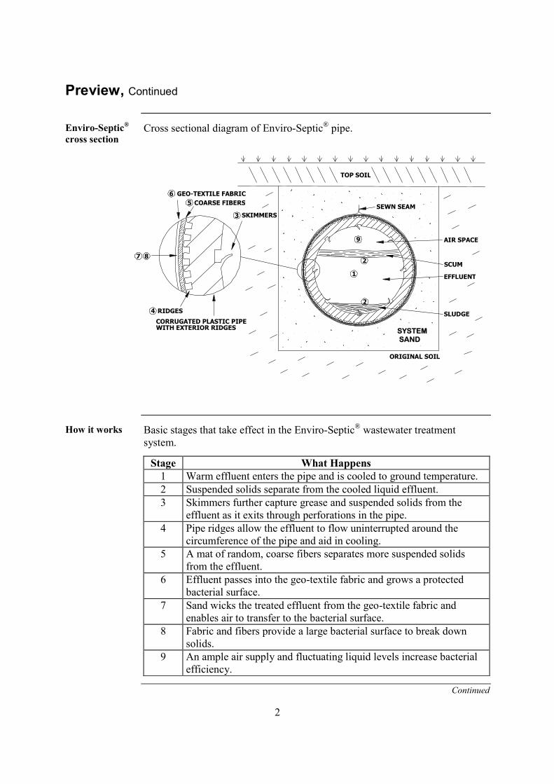
cross sectionCross sectional diagram of Enviro-Septic® pipe.
How it works Basic stages that take effect in the Enviro-Septic® wastewater treatmentsystem.
Stage What Happens1 Warm effluent enters the pipe and is cooled to ground temperature.2 Suspended solids separate from the cooled liquid effluent.3 Skimmers further capture grease and suspended solids from the
effluent as it exits through perforations in the pipe.4 Pipe ridges allow the effluent to flow uninterrupted around the
circumference of the pipe and aid in cooling.5 A mat of random, coarse fibers separates more suspended solids
from the effluent.6 Effluent passes into the geo-textile fabric and grows a protected
bacterial surface.7 Sand wicks the treated effluent from the geo-textile fabric and
enables air to transfer to the bacterial surface.8 Fabric and fibers provide a large bacterial surface to break down
solids.9 An ample air supply and fluctuating liquid levels increase bacterial
efficiency.
Continued
SYSTEMSAND

3
Preview, Continued
In this manual This manual contains the following sections.
Section PageA – TIntroductionT 4B – Design Criteria, Requirements, and Restrictions 5C – Sand and Fill Requirements 9D – Standard System Configurations 10E – Non-Standard System Configurations 19F – Venting Requirements 20G – Inspection Port Requirements 22H – Quick Reference Guide for Percolation Rates Up to 60
Minutes/Inch23
I – Quick Reference Guide for Percolation Rates of 61-90Minutes/Inch
28
System Installation Form Appendix AEnviro-Septic® Wastewater Treatment System TechnologyChecklist
Appendix B

4
Section AIntroduction
Purpose The purpose of this manual is to provide guidance in the design and installationof the Presby Environmental, Inc., Enviro-Septic® wastewater treatmentsystem products.
PresbyEnvironmental,Inc., standards
All systems using Presby Environmental, Inc., Enviro-Septic® wastewatertreatment system products must be designed and installed in compliance withthe procedures and specifications described in the Enviro-Septic®
PMassachusetts Design and Installation Manual (available for download @Twww.presbyenvironmental.comT) and summarized in this Quick ReferenceGuide.
State standards Title 5, 310 CMR 15.000, the State Environmental Code for Massachusettscovers issues not addressed in this manual. Title 5 requirements takeprecedence unless specifically changed by the General Use or Remedial Useapprovals issued for the Enviro-Septic® system.
Certificationrequired
MassDEP requires that all installers be trained and certified by PresbyEnvironmental, Inc.
Presby Environmental, Inc. requires all installers and designers to betrained and certified.
Certification is obtained by attending the “Enviro-Septic® Designer andInstaller Certification Course” presented by Presby Environmental, Inc.,or its sanctioned representatives.
Presby Environmental, Inc. highly recommends that all individualsinvolved in the approval or permitting process also attend thesecertification courses.
Until designers and installers are certified, designs and installations mustbe approved/inspected by Presby Environmental, Inc., or its sanctionedrepresentatives.
UNoteU: While this Quick Reference Guide includes essentials, certificationcourses cover a larger range of topics in much greater detail. Thedocumentation materials provided at these courses is likewise more detailed.
“SystemInstallationForm” required
Installers of Enviro-Septic® systems shall provide Presby Environmental, Inc.,and the local approving authority with a copy of a completed “SystemInstallation Form” for each new or remedial system installed. This form mayalso be downloaded from our website, www.presbyenviromental.com.
UReferenceU: See “Appendix A – System Installation Form.”
Technicalsupport
Presby Environmental, Inc. provides technical support to all individuals usingour products. For questions about the information contained in this manual,please review our website at www.presbyenvironmental.com or contact us at1-800-473-5298.

5
Section BDesign Criteria, Requirements, and Restrictions
Introduction This section contains a variety of criteria, requirements, and restrictions fordesigning Enviro-Septic® wastewater treatment systems.
Subjects covered This table contains the subjects covered and the page location of each.
Subject PageDepth of cover 5Design flow 5Distribution box required 5Documentation required 6Elevation Table required (sloping systems only) 6High flow system configurations 6Inspection Ports 6Line orientation 6Loading limits 6Low flow system configuration 6Maximum/minimum line lengths 6Minimum separation distances 7New construction sizing 7Percolation rate restriction 7Pressure distribution lines 7Raised systems minimum fill extensions 7Remedial bed design restrictions – 61-90 percolation rates 7Reserve area 7System Installation Form 8System size limitation 8Venting requirements 8
Depth of cover The minimum total depth of cover on Enviro-Septic® lines is 10 inches: 6” ofSystem Sand plus 4” of topsoil. Enviro-Septic® pipe with 12” of structuralcover is designed for H-10 loading, and Enviro-Septic® pipe with 18” ofstructural cover is designed for H-20 loading.
Design flow Design flow is defined in Title 5, 310 CMR 15.002. Design flow criteria arepresented in 310 CMR 15.203. When design flow is not established in 310CMR 15.203, water meter readings can be used in accordance with 310 CMR15.203 (6). Residential system design flows below 330 gallons per day requirea deed restriction.
Distribution boxrequired
All systems shall be designed and installed using distribution boxes. Theoutlet of the distribution box shall be at least 2” above the inlet of the highestEnviro-Septic® line with the connecting pipe slope not less than 2%.
6
Design Criteria, Requirements, and Restrictions, Continued
Documentationrequired
The designer must provide the system owner with copies of the State’sCertification for General Use and/or Approval for Remedial Use, an “Enviro-Septic® Wastewater Treatment Operating Manual” and a “TechnologyChecklist.” In addition, a “System Installation Form” must be completed bythe Installer and provided to both the local approving authority and PresbyEnvironmental, Inc. These documents can be downloaded from our website:Twww.presbyenvironmental.comT.
UReferences: See “Appendix A, System Installation Form” and Appendix B,“Technology Checklist.”
Elevation Tablerequired onplans (slopingsystems only)
The construction plan for all sloping systems must include a table listing theelevations for each line in each bed of the Enviro-Septic® system.
High flowsystemconfigurations
High flow is a “design flow” greater than 500 GPD.High flows in soils with perc rates of up to 60 min/inch require combinationor distribution box system configurations or multiple serial beds; each outletline from the distribution box is limited to a maximum of 500 GPD.All high flow systems in soils with perc rates of 61-90 min/inch requiremultiple serial beds each limited to a maximum of 500 GPD.
Inspection Portsrequired
All systems require an inspection port. See Section G, Inspection PortRequirements, p. 21.
Line orientation Enviro-Septic® lines must be laid level and should run parallel to contours(perpendicular to sloping terrain).
Loading limits Each serial bed, line of a distribution box system, and section of acombination system has a maximum design flow of 500 GPD.
Low flow systemconfiguration
Low flow is a “design flow” of 500 GPD or less. Basic serial systemconfiguration is preferred for low flow systems.
Minimum/maxi-mum linelengths
No single line of any system may exceed 100’ or be less than 30’ in length, butthe multiple lines of a basic serial system or section of a combination systemmay total more than 100’ in length when connected in series using raisedconnections.
UNote: In some instances site conditions may require lines shorter than 30’.These are non-standard system configurations.
UReference: See “Section E – Non-Standard System Configurations,” p. 18.

7
Design Criteria, Requirements, and Restrictions, Continued
Minimumseparationdistances
Setback distances are measured from the outer edge of the System Sand. Thedistances to the estimated high groundwater elevation (EHGW) and otherrestrictive features are measured from the bottom of the 6” of System Sandbelow the bottom of the Enviro-Septic® pipe. In sloping systems that require a3’ System Sand extension, setbacks are measured from the outer edge of theSystem Sand extension area.
Newconstructionsizing
For new construction, the system owner initially shall size a soil absorptionsystem in accordance with 310 CMR 15.242 to demonstrate that aconventional Title 5 soil absorption system using aggregate, including areserve area, can be installed on the site. The system owner may then size thesoil absorption system for the Enviro-Septic® system.
Percolation raterestriction
General Use systems for new construction are limited to sites with apercolation rate of 1 to 60 min/inch. Remedial systems can be constructedwhere the percolation rate is from 1 to 90 min/inch.
Pressuredistributionlines
The use of pressure distribution lines in Enviro-Septic® wastewater treatmentsystems is prohibited.
Raised systemsminimum fillextensions
Raised systems that slope 10% or less require 3’ extensions on each side(including System Sand, surrounding sand, and topsoil) before tapering.
Raised systems that slope greater than 10% require 3’ extensions on threesides and a 5’ extension on the down slope side before tapering.
Tapering is to be 3:1 or less (maximum 2:1 with a variance).
Topsoil is required around the fill perimeter of raised systems.
All mounded systems shall be designed and constructed in accordancewith 310 CMR 15.255.UReference: See drawings on pp. 17-18.
Remedial beddesignrestrictions – 61-90 percolationrates
Remedial systems in soils with percolation rates greater than 60 and up to 90minutes per inch must be designed as basic serial systems. A multiple bedsystem uses a distribution box with flow equalizers. No bed in a basic serialmultiple bed system can have a design flow of more than 500 GPD. Bedsshall be separated by at least six feet of naturally occurring undisturbed soil.To accommodate construction access, additional separation distance may benecessary.
Reserve area For new construction a system must contain a reserve area the size of aconventional Title 5 soil absorption system using aggregate. For remedialsystems the system owner must demonstrate that sufficient reserve is notavailable so that the system can be designed without a reserve area.

8
Design Criteria, Requirements, and Restrictions, Continued
SystemInstallationForm
Installers of Enviro-Septic® systems shall provide Presby Environmental, Inc.,and the local approving authority with a copy of a completed “SystemInstallation Form” for each new or replacement system installed. This formcan also be downloaded from our website, www.presbyenvironmental.com.
UReference: See “Appendix A – System Installation Form.”
System sizelimitation
To meet Massachusetts’ requirements, at no time may an Enviro-Septic®
system be designed to have a sand bed area less than 60% of a conventionalTitle 5 aggregate system designed in accordance with 310 CMR 15.252 for thesame site. In addition, the minimum area for a system installed for newconstruction shall be 400 square feet.
Ventingrequirements
All systems must be vented. See Section F, Venting Requirements, p. 19.

9
Section CSand and Fill Requirements
Introduction This section describes the sand requirements for the Enviro-Septic®
wastewater treatment system.
System sandUAll configurationsU of Enviro-Septic® require a minimum of 6” of System Sandsurrounding the circumference of the pipe.UPercentage Restrictions35% or less of the total sand may be gravel.40%-90% of the total sand is to be coarse and very coarse sand.UGravel Quality RestrictionsNo gravel is to exceed ¾” in diameter.No gravel is smaller than 2mm/0.0787” in diameter. (It must not pass througha #10 sieve.)UCoarse Sand Quality RestrictionsNo coarse sand smaller than 0.5mm/0.0196” in diameter. (It must not passthrough a #35 sieve.)UFines Quality RestrictionsNo more than 2% of the total sand may pass through a #200 sieve.
UASTM StandardU: C-33 (concrete sand) meets the above requirements aslong as 2% or less of the sand passes through a #200 sieve.
Surroundingsand
Surrounding sand may be additional System Sand or Title 5 fill. Onlysurrounding sand may be placed under raised systems or where topsoil and soilhorizons with organic matter have been removed. (Surrounding sand should beeither System Sand or Title 5 fill, 310 CMR 15.255 (3))
Clean Fill Select on-site or imported soil material, free of organic matter and deleterioussubstances, free of stones and boulders greater than 6 inches in size. Tailings,clay or similar materials are prohibited. See 310 CMR 15.240 (9).
Perc Rates 1-60Perimeter sandbedrequirements
Systems sloping 10% or less require the System Sand area to extend aminimum of 1 foot around the perimeter of the Enviro-Septic® pipe.
Systems sloping greater than 10% require the System Sand area to extend aminimum of 1 foot around the perimeter of the Enviro-Septic® pipe, and anadditional 6” of System Sand, measured from the bottom of the Enviro-Septic®
pipe, must extend 3’ on the downslope side.
UReferences: See “Inground System Sections” diagrams, p. 16 and “Raised(Mounds) System Sections” diagrams, p. 17-18.

10
Section DStandard System Configurations
Introduction This section presents the standard configurations designs in which Enviro-Septic® systems should be designed and installed.
Elevation andslopeconfigurations
These line configurations may be designed as inground or raised systems onlevel or sloping terrain.
Sloping systems The percentage of slope refers to the slope of the Enviro-Septic® system, UnotU
the existing terrain. The maximum sand bed slope for all systems is 25%. Themaximum site slope is 3:1 (33%). A sloping system can be designed withmore than one distinct slope within the same bed. The minimum center-to-center spacing may vary within a bed depending upon each distinctive slopewithin the bed. Refer to Table B, p. 24.
Line orientation Enviro-Septic® lines must be laid level and should run parallel to contours(perpendicular to sloping terrain).
Distribution boxrequired
A distribution box is used to divide effluent equally to each outlet incombination, distribution box, multiple bed and pump systems.
UNote: MassDEP requires that all systems be designed and installed usingdistribution boxes which serve as observation ports. However, note that thedistribution box cannot serve as the required inspection port.
Velocityreduction
If the slope of piping from the septic tank to the Enviro-Septic® is 10% ormore up to a length of 50’, or 5% or more for lengths over 50’, a velocityreducer is necessary in the distribution box. A baffle or an inlet tee may be anadequate velocity reducer.
Flow equalizersrequired
All distribution boxes that divide effluent flow in pump or gravity systemsrequire flow equalizers in their outlets.
Pump systemdefinition
A pump system uses a pump to elevate effluent to the Enviro-Septic® system.Pump systems require a distribution box with equalizers for velocity reduction.Equalizers must be installed at each distribution box outlet that is dispersingeffluent to the Enviro-Septic® system.
UNote: When there is only one outlet from the distribution box, no equalizersare to be used.

11
In this section This section contains the following subjects.
Subject PageBasic Serial Systems 12Combination Systems 13-14Distribution Box Systems 15Inground System Sections 16Raised (Mound) System Sections 17Raised (Mound) System Sections with Impervious Barriers 18

12
ENVIRO-SEPTIC LINES
RAISED CONNECTIONS
SYSTEM SAND 1' BEYOND LINES
OFFSET ADAPTER TO VENT
OFFSET ADAPTERSOFFSET ADAPTERS COUPLINGS
D-BOX
ADDITIONAL 3' OF SYSTEM SANDDOWN-SLOPE SIDE OF SYSTEMS >10%
INSPECTION PORT
A MINIMUM OF ONE INSPECTION PORT REQUIRED ANDSHALL BE PLACED BETWEEN TWO ROWS. THE DISTRIBUTION
BOX DOES NOT COUNT AS AN INSPECTION PORT.
Basic Serial Systems
Introduction Basic serial distribution is preferred for single beds of 500 GPD or less andmultiple bed systems where each bed receives 500 GPD or less. Basic serialdistribution allows for quick development of a strong biomat in the first line,providing improved effluent treatment. Basic serial distribution provides alonger flow route to allow decomposition of solids, providing improved long-term treatment.
Definition A basic serial system is a single bed with a series of Enviro-Septic® linesconnected at alternating ends by raised connections using PVC sewer and drainpipe. These systems have a single inlet to the first line of the series and a ventat the end of the last line in the series. See diagram below.
Line length Each line of a basic serial system has a maximum length of 100’.
Basic serialsystem diagram
Plan view of an Enviro-Septic® basic serial system.
UNote: All systems require an inspection port. Refer to Section G, InspectionPort Requirements, p. 21.

13
Combination Systems
Introduction Combination distribution is required for systems with design flows greater than500 GPD and for multiple bed systems where each section receives no greaterthan 500 GPD. Combination distribution allows for quick development of astrong biomat in the first line of each section, providing improved effluenttreatment. Combination systems use a distribution box for dividing flowequally to multiple serial sections, providing longer flow routes that allowdecomposition of solids and providing improved long-term treatment.
Definition A combination system is a bed of two or more sections of Enviro-Septic® linesin serial configuration supplied equally through a distribution box. Eachsection of a combination system is a series of Enviro-Septic® lines connectedat the ends with raised connections, using offset adapters and PVC sewer anddrain pipe. An offset adapter is installed at each section inlet, and at the end ofeach section, which is then connected to a vent or vent manifold.
Loading Each section of a combination system has a maximum design flow of 500GPD.
Line length Each line of a combination system has a maximum length of 100’.
Section lengthrequirement
Each section of a combination system must have at least the same minimumlinear feet of pipe. The minimum linear feet of pipe per section is determinedby dividing the total linear feet required by the number of sections. A sectionmay exceed the minimum linear length. Lines within a section may vary inlength to accommodate site constraints.

14
SE
CT
ION
#2
SE
CT
ION
#1
D-BOX / FLOWDIVIDER
OFFSET ADAPTERS
ENVIRO-SEPTIC LINES
COUPLINGSRAISED CONNECTIONS
OFFSET ADAPTERS
SYSTEM SAND 1' BEYOND LINES
OFFSET ADAPTER TO VENT MANIFOLD
ADDITIONAL 3' OF SYSTEM SANDDOWN-SLOPE SIDE OF SYSTEMS >10%
INSPECTION PORT
A MINIMUM OF ONE INSPECTION PORT REQUIRED AND SHALL BE PLACED BETWEENTWO ROWS. THE DISTRIBUTION BOX DOES NOT COUNT AS AN INSPECTION PORT.
Combination Systems
Combinationsystem diagram
Plan view of an Enviro-Septic® combination system.
UNote: All systems require an inspection port. See Section G, Inspection PortRequirements, p. 21.

15
SYSTEM SAND 1' BEYOND LINES
OFFSET ADAPTERS TO VENT MANIFOLD
TO VENT MANIFOLD
ENVIRO-SEPTIC LINES
COUPLINGSOFFSET ADAPTERS
D-BOX /FLOW DIVIDER
OFFSET ADAPTERS
ADDITIONAL 3' OF SYSTEM SANDDOWN-SLOPE SIDE OF SYSTEMS >10%
INSPECTION PORT
A MINIMUM OF ONE INSPECTION PORT REQUIRED AND SHALL BE PLACED BETWEENTWO ROWS. THE DISTRIBUTION BOX DOES NOT COUNT AS AN INSPECTION PORT.
Distribution Box (“D-Box”) Systems
Introduction The distribution box divides flow equally to individual lines of Enviro-Septic®
pipe.
Definition A distribution box system is a bed with each Enviro-Septic® line suppliedequally through an outlet from the distribution box. Each Enviro-Septic® lineof a distribution box system has one offset adapter at each line inlet and oneoffset adapter at the end of each line, which is connected to a vent or ventmanifold.
Flow equalizersrequired
All distribution boxes that divide effluent flow in pump or gravity systemsrequire flow equalizers in their outlets.
Line lengthrequirement
Each line of a distribution box system has a maximum length of 100’. Eachline of a distribution box system must have the same minimum linear feet ofpipe. The minimum linear feet of each line is determined by dividing the totallinear feet required by the number of lines.
Distributionbox systemdiagram
Plan view of an Enviro-Septic® distribution box system:
UNoteU: All systems require an inspection port. See Section G, Inspection PortRequirements, p. 21.

16
MINIMUM COVER 10"
ENVIRO-SEPTIC LINES
LOW VENT
SEPARATION DISTANCE
SYSTEM SAND 6" ABOVE AND BELOWENVIRO-SEPTIC LINES
CLEAN FILL OVERSYSTEM SAND PER310 CMR 15.240 (9)TOPSOIL
NATURALLY OCCURRINGPERVIOUS MATERIAL
1 2 3 4 5 6
RESTRICTIVE FEATURE
1' MIN. 1' MIN.
SYSTEM SAND 6" ABOVE AND BELOWENVIRO-SEPTIC LINES
NATURALLY OCCURRINGPERVIOUS MATERIAL
TOPSOIL
CLEAN FILL OVERSYSTEM SAND PER310 CMR 15.240 (9)
1 2 3 4 5 6
LOW VENT
RESTRICTIVE FEATURE
SEPARATION DISTANCE
1' MIN. 1' MIN.
ENVIRO-SEPTIC LINES
MINIMUM COVER 10"
RESTRICTIVE FEATURE
LOW VENT
SEPARATION DISTANCE
MINIMUMCOVER 10"
ENVIRO-SEPTIC LINES1' MIN. 1' MIN.
SYSTEM SAND 3'AT DEPTH OF 6"
SYSTEM SAND 6" ABOVE ANDBELOW ENVIRO-SEPTIC LINES
TOPSOIL
CLEAN FILL OVER SYSTEMSAND PER 310 CMR 15.240 (9)
NATURALLY OCCURRINGPERVIOUS MATERIAL
12
34
56
Inground System Sections
Introduction Inground Enviro-Septic® systems are the preferred configuration for sites withno soil constraints to limit placement.
Definition Inground systems are configurations where the bottom of the System Sand bedis below the existing grade.
Inground level section
Inground sloping to 10%
Inground sloping >10%
17
ENVIRO-SEPTIC LINES
LOW VENT
EXISTINGGROUND
1' MIN. 1' MIN.
LEVELMINIMUM COVER 10"
3:1
TO INV. EL. AT 15'
15'
ESHGW
CLEAN FILLFREE OF STONES
AND BOULDERS > 6"
SYSTEM SAND6" ABOVE AND BELOWENVIRO-SEPTIC LINES
CLEAN FILL
SEPARATION DISTANCE
SURROUNDING SANDIN OVERDIG AREA
(TYPICAL) SURROUNDING SAND(WHEN NEEDED)
OVERDIGAREA TYP
5'OVERDIG AREA TYP
NATURALLY OCCURRINGPERVIOUS MATERIAL
TOPSOIL2 3 4 5 6
15'
EXISTINGGROUND
ESHGW
ENVIRO-SEPTIC LINES
LOW VENT
EXISTINGGROUND
1' MIN.1' MIN.
MINIMUM COVER 10"
3:1
LEVELLEVEL
3:1
15'15'
2 3 4 5 6
SEPARATION DISTANCE
SYSTEM SAND 6" ABOVE ANDBELOW-ENVIRO-SEPTIC LINES
CLEAN FILLFREE OF STONES
AND BOULDERS > 6"
5'OVERDIG AREA TYP
SURROUNDINGSAND IN OVERDIGAREAS (TYPICAL)
SURROUNDING SAND(WHEN NEEDED)
CLEAN FILL
TOPSOIL
NATURALLY OCCURRINGPERVIOUS MATERIAL
1' MIN. 1' MIN.
4:1
3:1
MINIMUM COVER 10"
15'
TO INV. EL. AT 15'
ESHGW
CLEAN FILLFREE OF STONES
AND BOULDERS > 6"
SYSTEM SAND6" ABOVE AND BELOWENVIRO-SEPTIC LINES
CLEAN FILL
RESTRICTIVE FEATURE
SEPARATION DISTANCE
5'(if required)
SURROUNDINGSAND IN OVERDIGAREA (TYPICAL)
SURROUNDING SAND(WHEN NEEDED)
NATURALLY OCCURING
PERVIOUS MATERIAL
TOPSOIL
23
45
6
ENVIRO-SEPTIC LINES
LOW VENT
EXISTINGGROUND
SYSTEM SAND 3'AT DEPTH OF 6"
LEVEL
Raised (Mounds) System Sections
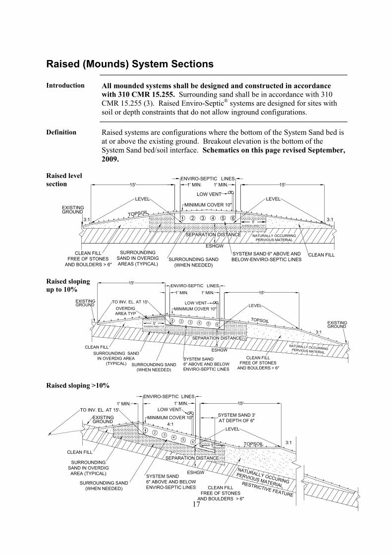
Introduction All mounded systems shall be designed and constructed in accordancewith 310 CMR 15.255. Surrounding sand shall be in accordance with 310CMR 15.255 (3). Raised Enviro-Septic® systems are designed for sites withsoil or depth constraints that do not allow inground configurations.
Definition Raised systems are configurations where the bottom of the System Sand bed isat or above the existing ground. Breakout elevation is the bottom of theSystem Sand bed/soil interface. Schematics on this page revised September,2009.
Raised levelsection
Raised slopingup to 10%
Raised sloping >10%

18
5'
6" MIN.
IMPERVIOUSBARRIER
3:1 SLOPEAFTER BARRIER
SURROUNDING SANDIN OVERDIG AREA
(TYPICAL)
SURROUNDING SAND(WHEN NEEDED)
OVERDIG AREA TYP
SEPARATION DISTANCE 1' MIN.
5'
NATURALLY OCCURRINGPERVIOUS MATERIAL
TOPSOIL
ESHGW
ENVIRO-SEPTIC LINES
LOW VENT
EXISTINGGROUND
1' MIN.1' MIN.
MINIMUM COVER 10"
3:1
LEVELLEVEL
3:1
15'15'
2 3 4 5 6
SYSTEM SAND 6" ABOVE ANDBELOW ENVIRO-SEPTIC LINES
CLEAN FILLFREE OF STONES
AND BOULDERS > 6"
15'
ESHGW
CLEAN FILLFREE OF STONES AND
BOULDERS > 6"
SYSTEM SAND6" ABOVE AND BELOWENVIRO-SEPTIC LINES
CLEAN FILL
5'
5'
6" MIN.
IMPERVIOUSBARRIER
1' MIN.
RESTRICTIVE FEATURE
ENVIRO-SEPTIC LINES
LOW VENT
EXISTINGGROUND
1' MIN. 1' MIN.
LEVELMINIMUM COVER 10"
3:1
OVERDIG AREA TYP
SURROUNDING SANDIN OVERDIG AREA
(TYPICAL)SURROUNDING SAND
(WHEN NEEDED)
SEPARATION DISTANCE
3:1 SLOPEAFTER BARRIER
TOPSOIL
NATURALLY OCCURRINGPERVIOUS MATERIAL
2 3 4 5 6
SLOPE TO MATCHINV. EL. AT 15'
Raised (Mounds) Sections with Impervious Barriers
Application To be used in conjunction with MassDEP’s UGuidelines for Design andInstallation of Impervious Barriers and Slope Stabilization For Title 5SystemsU, which supplements UTitle 5, 310 CMR 15.255U, Systems Constructedin Fill.
Note Height of impervious barrier is to, or just below, intersection of sloped fill designed tomeet breakout elevation at 15'. Title 5 fill (surrounding sand) goes to top of barrier.Breakout elevation is bottom of the System Sand bed/soil interface. Schematics onthis page revised September, 2009.
Raised levelsection
Raised slopingto 10%
Raised sloping >10%

19
SEC #1
SEC #2
SEC #3
SEC #4
D-BOX IN A COMBINATION SYSTEM
MANIFOLD TO LOW VENT
10'-30'
INSPECTION PORT
100' LINE MAXIMUM 100' LINE MAXIMUM
100' LINE MAXIMUM100' LINE MAXIMUM
MANIFOLD TO LOW VENT
LOW VENT
D-BOX IN A COMBINATION SYSTEM
DBOX
PREFERRED CONFIGURATION
LESS PREFERRED CONFIGURATION
4" PVC S&D Pipe
OFFSET ADAPTERSOFFSET ADAPTERS
SIDE VIEW
FLOW
LEVELROTATE TO
22° PVC Bend
ENVIRO-SEPTIC LINES
TOP VIEW
MAX. 4"MAX. 4"
ENVIRO-SEPTIC LINES
MAX. 4" MAX. 4"4" PVC S&D Pipe22° PVC Bend
Section ENon-Standard System Configurations
Introduction Non-standard configurations may accommodate line lengths longer than 100’and pipe lines shorter than 30’. Non-standard configurations can only be usedin soils with perc rates less than 60 min./inch. It is preferable not to have linesshorter than 30’ because this will create more turbulence, interfering with thesettling of solids. It is preferable not to have line lengths longer than 100’since these configurations do not create the ideal conditions for development ofa healthy biomat; insufficient flow in lines over 100’ impedes the wet and drycycling which promotes aerobic activity.
Total linear feetrequirement
Each line of a distribution box system and each section of a combinationsystem must have the same minimum linear feet of pipe.A section or line may be less than the minimum 30’ (if necessitated by siteconstraints) by configuring it as a combination system. However, thecombined length of the first lines in each section must be a minimum of 30’.Where site constraints dictate a long, narrow configuration, two lines of amaximum length of 100’ can be connected by PVC sewer and drain pipe asshown in the drawing below labeled “Less Preferred Configuration.” In thissituation, it would be better to place the distribution box between the linescreating a butterfly configuration as shown in drawing below labeled“Preferred Configuration.”
Non-standardrestriction
Non-standard system configurations are not allowed for soils with percolationrates of 61-90 min/inch.
Combination configuration divides effluentflow evenly to the first line in each section
with pipe lengths less than 30’. Initialloading (cumulative lengths of the first
lines of each section) must be ≥ 30’.
Straight connector (detail below)

20
LOW VENT
MIN. 10'
FINAL GRADE
HIGH VENT
D-BOX
SUPPORT
Section FVenting Requirements
General rule Low and high vents are required for all systems to ensure that air isdrawn completely through the entire Enviro-Septic® system.
No additional vents may be located between the high vent and low vent. The opening of the high vent must be at least 10 feet above the opening
of the low vent. High vents should maintain the same flow capacity as low vents if
possible. Connections within the system must also have similar flowcapacities.
UPurpose: Venting design, installation, and maintenance must ensure that everylinear foot of Enviro-Septic® pipe in all serial beds, sections, or linesreceives oxygen to accommodate natural biologic activity.
Low ventlocations
Low vents are installed through an offset adapter at the end of each: serial system or bed section of a combination system line of a distribution box systemNote: Low vent inlet must be a minimum of 3’ above final grade.
High ventlocations
High vents are installed in a variety of locations based on the system design.
The roof vent can function as the high vent if there are no pumps orrestrictions between the low vent and the roof vent.
If a restriction is placed between the low vent and the roof vent, a high ventis required through an unused distribution box outlet.
In pumped systems a high vent is required through an unused distributionbox outlet.
In a gravity system, do not install a third vent between the high and lowvents, as this will short-circuit the flow, preventing air from passingthrough the Enviro-Septic® System and impairing the natural biologicactivity.
High vent ondistribution box
This diagram shows a high vent installed in a distribution box. Thisconfiguration is required ONLY in pump systems or when other restrictionsinterfere with the flow of air to the high (roof) vent.

21
NO
TA
LL
RO
WS
AR
ES
HO
WN
SLOPE
LO
WV
EN
T
HIG
HV
EN
T
FINAL GRADE
HIGH GROUND WATER TABLE
SLOPESLO
PE
SLOPE
DISTRIBUTION BOX
2" MIN OVER2" MIN OVER
PLACE WASHEDSTONE AROUND
ELBOW
ENVIRO-SEPTICPIPE
HIGH GROUND WATER TABLE
10
'M
IN3
'
MIN
DRILL SEVERAL 1/4"Ø HOLES AT LOW POINT OF ELBOWTO DRAIN CONDENSATION. LOW POINT MUST BE ABOVE
SEASONAL HIGH WATER TABLE.
PLACE WASHED STONEAROUND ELBOW
DISGUISEVENT IN TREEDISGUISE LOW
VENT IN SHRUBS
SCREEN VENTOPENINGS
TOP OFDISTRIBUTION
BOX
REMOTE VENTING(DO NOT SCALE)
OFFSET ADAPTERS
D-BOX VENT MANIFOLD
DISTRIBUTION SYSTEM D-BOX
VENT MANIFOLD
OFFSET ADAPTERS
COMBINATION SYSTEM
Venting Requirements, Continued
Vent manifolds A vent manifold can be incorporated to connect the ends of a number ofsections or lines of Enviro-Septic® pipe to a single vent opening. One 4” ventis required for every 1,000’ of pipe. A 6” manifold and vent stack may vent upto 3,000’ of pipe.
Remote ventpiping slope
Remote vent piping should slope downward toward the system to preventmoisture from collecting in the piping and blocking air passage. If siteconditions do not allow the pipe to slope back toward the system, the low pointof the connecting pipe should be drilled to allow drainage and must be locatedabove the EHGW. The connecting pipe invert must be above the highest pointof the distribution box and all of the connection lines to the Enviro-Septic®
system.
Avoid ShortCircuitingVenting
At no time should there be openings into a distribution box, septic tank, etc.since this will short circuit the flow of air and interfere with the properfunctioning of the vents.
22
6"
SYSTEM SAND
4"Ø PERFORATED INSPECTION PORT TO BOTTOM OFSYSTEM SAND AND THREADED CAP WITHIN 3" OF FINAL
GRADE. WRAP PIPE WITH PERMEABLE GEOTEXTILEFABRIC TO ELIMINATE SAND INFILTRATION.
Section GInspection Port Requirements
Massachusettsrequiresinspection ports
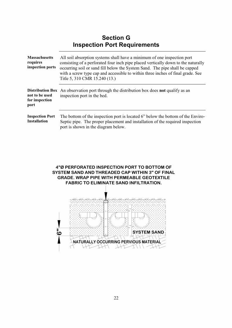
All soil absorption systems shall have a minimum of one inspection portconsisting of a perforated four inch pipe placed vertically down to the naturallyoccurring soil or sand fill below the System Sand. The pipe shall be cappedwith a screw type cap and accessible to within three inches of final grade. SeeTitle 5, 310 CMR 15.240 (13.)
Distribution Boxnot to be usedfor inspectionport
An observation port through the distribution box does not qualify as aninspection port in the bed.
Inspection PortInstallation
The bottom of the inspection port is located 6” below the bottom of the Enviro-Septic pipe. The proper placement and installation of the required inspectionport is shown in the diagram below.

23
Section HQuick Reference Guide for Percolation Rates Up to
60 Minutes/Inch
Purpose The unique Enviro-Septic® design provides an infinite number of systemconfigurations that vary in length, width, slope, and shape. The purpose of thisguide is to help designers compare layouts for any site quickly and easily.
We recommend designers read the entire Enviro- Septic® MassachusettsDesign and Installation Manual (available for download from our website,www.presbyenvironmental.com) before using this Quick Reference Guide.Reminder: Presby Environmental, Inc. requires all designers and installers tobe trained and certified. See “Certification Required,” p. 4.
Exceptionsrequire variance
Exceptions to any requirements used in this Quick Reference Guide require avariance from the local approving authority.
Minimumseparationdistances
Title 5, 310 CMR 15.000 of the Massachusetts State Environmental Codeestablishes rules for minimum vertical and horizontal separation distances.Setback distances are measured from the outer edge of the System Sand. Thedistances to EHGW and other restrictive features are measured from thebottom of the 6” of System Sand below the Enviro-Septic® pipe.
Systemconfiguration
Basic serial configuration is recommended for low flow systems. High flowsystems are preferably designed as combination systems or multiple serial bedsystems, but distribution box systems may also be used.
Procedure Complete these tasks to size a single level Enviro-Septic® system.
Task 1: Determine the linear feet of Enviro-Septic® pipe required.
Use the percolation rate and the number of bedrooms or the commercial GPD inTable A below to determine the linear feet of Enviro-Septic® pipe required.
Table A: Linear FootageNumber of BedroomsPerc rate
Min/Inch 2 3 4 5 6 Add'l RoomCommercialPer 100 GPD
1-9 100 150 200 250 300 50 50
10-13 110 165 220 275 330 55 55
14-19 120 180 240 300 360 60 60
20-30 130 195 260 325 390 65 65
31-40 140 210 280 350 420 70 70
41-50 150 225 300 375 450 75 75
51-60 160 240 320 400 480 80 80
UExample: A three-bedroom home with an 18 min/inch percolation raterequires 180 feet of pipe.
UNote: Each bedroom has a design flow of 110 GPD.

24
Quick Reference Guide for Percolation Rates Up to 60Minutes/Inch, Continued
Task 2: Determine the percentage of slope on the proposed system.
UNoteU: The maximum slope for a sand bed system is 25%. However, the site slopemay be greater if fill or excavation is used to keep the system slope withinthe maximum.
Do you know the percentage of slope on the proposed system?
If yes, go to Task 3.
If no, follow this procedure to determine the percentage of system slope.
Step Action1 Identify the highest elevation of the proposed system site.2 Identify the lowest elevation of the proposed system site.3 Subtract the lowest elevation from the highest elevation = elevation
change.4 Measure the horizontal distance between the two elevations =
horizontal length.5 Divide the elevation change by the horizontal length = percentage of
site slope.6 Choose a percentage of slope to be used for the system.
UNoteU: The system slope does not need to be the same as the site slope.7 Go to Task 3.
Task 3: Determine the minimum center-to-center pipe spacing.
Use the percolation rate and the percentage of system slope in Table B below todetermine the required minimum center-to-center pipe spacing for a sand bed.
Table B: Pipe Spacing
Percentage of Percolation Rate Min/InchSystem Slope 1-10 11-20 21-30 31-40 41-50 51-60
0-10% 1.5’ 1.5’ 1.75’ 2.0’ 2.5’ 3.0’
11-15% 1.5’ 1.75’ 2.0’ 2.25’ 2.75’ 3.25’
16-20% 1.75’ 2.0’ 2.25’ 2.5’ 3.0’ 3.5’
21-25% 2.0’ 2.25’ 2.5’ 2.75’ 3.25’ 3.75’
UExampleU: A slope of ten percent or less with an 18 min/inchpercolation rate requires pipe spacing of 1.5’.
Continued

25
Quick Reference Guide for Percolation Rates Up to 60Minutes/Inch, Continued
Task 4: Determine pipe line layout.
IF... THEN use Table C below to...system length is nota limiting factor(Preferred)
find the pipe “Line Length/Ft” in the left column follow that row across to a number equal to or greater than the
required “Linear Feet of Enviro-Septic®” follow that column down through the “# of Lines” row and across
left to the required “Ctr to Ctr Spacing.”system length is alimiting factor
find the pipe spacing in the bottom left hand column and follow thatrow across to the desired layout width
follow that column up through the “# of Lines” row and up to therequired “Linear Feet of Enviro-Septic®”
follow that row left to determine the pipe line length.
UNote: Dark shading in table highlights figures used in the example.
Line Table C: Length and WidthLength/Ft Linear Feet of Enviro-Septic®
20 40 60 80 100 120 140 160 180 200 220 240 260 280 30025 50 75 100 125 150 175 200 225 250 275 300 325 350 37530 60 90 120 150 180 210 240 270 300 330 360 390 420 45035 70 105 140 175 210 245 280 315 350 385 420 455 490 52540 80 120 160 200 240 280 320 360 400 440 480 520 560 60045 90 135 180 225 270 315 360 405 450 495 540 585 630 67550 100 150 200 250 300 350 400 450 500 550 600 650 700 75055 110 165 220 275 330 385 440 495 550 605 660 715 770 82560 120 180 240 300 360 420 480 540 600 660 720 780 840 90065 130 190 260 325 390 455 520 585 650 715 780 845 910 97570 140 210 280 350 420 490 560 630 700 770 840 910 980 105075 150 225 300 375 450 525 600 675 750 825 900 975 1050 112580 160 240 320 400 480 560 640 720 800 880 960 1040 1120 120085 170 255 340 425 510 595 680 765 850 935 1020 1105 1190 127590 180 270 360 450 540 630 720 810 900 990 1080 1170 1260 135095 190 285 380 475 570 665 760 855 950 1045 1140 1235 1330 1425100 200 300 400 500 600 700 800 900 1000 1100 1200 1300 1400 1500
# of Lines 2 3 4 5 6 7 8 9 10 11 12 13 14 15Ctr to CtrSpacing
1.50 2.50 4.00 5.50 7.00 8.50 10.00 11.50 13.00 14.50 16.00 17.50 19.00 20.50 22.001.75 2.75 4.50 6.25 8.00 9.75 11.50 13.25 15.00 16.75 18.50 20.25 22.00 23.75 25.502.00 3.00 5.00 7.00 9.00 11.00 13.00 15.00 17.00 19.00 21.00 23.00 25.00 27.00 29.002.25 3.25 5.50 7.75 10.00 12.25 14.50 16.75 19.00 21.25 23.50 25.75 28.00 30.25 32.502.50 3.50 6.00 8.50 11.00 13.50 16.00 18.50 21.00 23.50 26.00 28.50 31.00 33.50 36.002.75 3.75 6.50 9.25 12.00 14.75 17.50 20.25 23.00 25.75 28.50 31.25 34.00 36.76 39.503.00 4.00 7.00 10.00 13.00 16.00 19.00 22.00 25.00 28.00 31.00 34.00 37.00 40.00 43.003.25 4.25 7.50 10.75 14.00 17.25 20.50 23.75 27.00 30.25 33.50 36.75 40.00 43.25 46.503.50 4.50 8.00 11.50 15.00 18.50 22.00 25.50 29.00 32.50 36.00 39.50 43.00 46.50 50.003.75 4.75 8.50 12.25 16.00 19.75 23.50 27.25 31.00 34.75 38.50 42.25 46.00 49.75 53.504.00 5.00 9.00 13.00 17.00 21.00 25.00 29.00 33.00 37.00 41.00 45.00 49.00 53.00 57.004.25 5.25 9.50 13.75 18.00 22.25 26.50 30.75 35.00 39.25 43.50 47.75 52.00 56.25 60.504.50 5.50 10.00 14.50 19.00 23.50 28.00 32.50 37.00 41.50 46.00 50.50 55.00 59.50 64.004.75 5.75 10.50 15.25 20.00 24.75 29.50 34.25 39.00 43.75 48.50 53.25 58.00 62.75 67.505.00 6.00 11.00 16.00 21.00 26.00 31.00 36.00 41.00 46.00 51.00 56.00 61.00 66.00 71.00
Layout Width/Ft.
Continued

26
Quick Reference Guide for Percolation Rates Up to 60Minutes/Inch, Continued
Task 5: Calculate the total System Sand bed area.
Massachusetts requires that Enviro-Septic® systems be no less than 60% of thearea of a pipe and aggregate system and no less than 400 square feet. Completethis task to determine minimum sand bed area size.
For systems sloping less than 10%, add two feet to the layout width and two feetto the line length from Table C; multiply these figures to obtain the sand bed areain sq.ft. For systems sloping greater than 10%, add 5 feet to the system width(the required one foot of perimeter sand on each side, plus the 3 foot extension =5 feet total) and add two feet to the pipe length; multiply these two figures toobtain the sand bed area in sq. ft.
If the area calculated above is less than the minimum sand bed area size requiredby Massachusetts in Table D, see “Increasing sand bed area footage,” next page.
Table D – Minimum Sand bed Area Size (sq.ft.)PERC 2 BEDROOM 220 GPD 3 BEDROOM 330 GPD 4 BEDROOM 440 GPD 5 BEDROOM 550 GPD
RATE SOIL CLASS SOIL CLASS SOIL CLASS SOIL CLASS
Min/Inch I II III IV I II III IV I II III IV I II III IV
1-5 400 400 400 400 400 440 446 550
6 400 400 400 400 400 440 471 550
7 400 400 400 400 400 440 485 550
8 400 400 400 400 400 440 500 550
10 400 400 440 550
15 400 400 400 535 471 714 589 892
20 400 400 400 582 498 776 623 971
25 400 400 495 600 660 800 825 1000
30 400 455 600 683 800 910 1000 1138
40 528 792 1056 1320
50 660 660 990 990 1320 1320 1650 1650
60 880 880 1320 1320 1760 1760 2200 2200
PERC 6 BEDROOM 660 GPD ADD'L. BEDROOM 110 GPD COMMERICAL PER 100 GPD
RATE SOIL CLASS SOIL CLASS SOIL CLASS
Min/Inch I II III IV I II III IV I II III IV
1-5 535 660 89 110 81 100
6 566 660 94 110 86 100
7 582 660 97 110 88 100
8 600 660 100 110 91 100
10 660 110 100
15 707 1070 117 178 107 162
20 747 1165 124 194 113 176
25 990 1200 165 200 150 182
30 1200 1366 200 227 182 207
40 1584 264 240
50 1980 1980 330 330 300 300
60 2640 2640 440 440 400 400

27
Quick Reference Guide for Percolation Rates of Up to 60Minutes/Inch, Continued
Increasing sandbed area footage
Our 3-bedroom home with an 18 min/inch perc rate requires 180 linear feet ofpipe with 1.5’ center-to-center spacing. Using Table C, with 30’ lines, theEnviro-Septic® pipe layout width is 8.5’ giving a sand bed area of 32’x 10.5’for a total of 336 square feet of sand bed. To meet the Massachusettsminimum bed area requirement of 400 square feet for soil class II from TableD, our sand bed area must be increased. Our sand bed area may be increasedby adding width and/or length to the system.
UNote: When using Table D, if exact perc rate is not shown, round up to thenearest perc rate. In our example, the 18 min/inch perc rate rounds up to 20min/inch.
UAdding width: To meet the minimum sand bed area size required, theminimum pipe spacing may be increased. Add 2 feet to the pipe length anddivide the minimum sand bed area size by that amount to obtain the minimumsand bed width. Subtract 2 feet from the minimum sand bed width and find theline spacing that provides at least that layout width in Table C. For slopesgreater than 10%, subtract 5 feet from the minimum sand bed width beforereferring to Table C for line spacing.
UAdding width example: To increase the sand bed area footage in our exampleby adding width, divide 400’ by 32’ to obtain a minimum sand bed width of12.5’. Subtract 2’ from that to obtain the minimum Enviro-SepticP
®P pipe layout
width of 10.5’. Table C indicates that a line spacing of 1.75’ center-to-centerprovides a layout width of only 9.75’ for a 6-line system; therefore, a linespacing of 2.0’ center-to-center and a layout width of 11’ is needed to providea sand bed width of 13’ to meet the required 12.5’ minimum sand bed width.This now gives us a sand bed area of 416 square feet (13’x32’) and a systemconfiguration of 6-30’ lines spaced 2’ center-to-center.
UAdding length:U Add 2 feet to the system width (5 feet for slopes over 10%)and divide the minimum sand bed area size by that amount to obtain theminimum sand bed length required. Subtract 2 feet from the minimum sandbed length to obtain the pipe line length.
UAdding length example: To increase the sand bed area footage in our exampleby adding length, divide 400’ by 10.5’ to obtain a sand bed length of 39’.Subtract 2’ from that to obtain a line length of 37’. 39’x10.5’ equals 410square feet of sand bed area. The system configuration would be 6-37’ linesspaced 1.5’ center-to-center.
UNote: This example uses 6-37’ line lengths. Limiting pipe to 5’ and 10’lengths makes systems simpler to construct. This system would bemore easily installed as 6-40’ lines, eliminating the need to cut the pipe.
28
Section IQuick Reference Guide for Percolation Rates of 61-90
Minutes/Inch
Introduction Systems in high-density soils or soils with slow percolation rates are limited inconfiguration to adequately disperse and treat effluent and minimizegroundwater mounding.
Purpose The purpose of this guide is to help designers choose system layouts forpercolation rates in the 61-90 minutes/inch range.
We recommend designers read the entire Enviro-Septic® Massachusetts Designand Installation Manual (available for download from our website,Twww.presbyenvironmental.comT) before using this Quick Reference Guide.Reminder: Presby Environmental, Inc. requires all designers and installers tobe trained and certified. See “Certification Required,” p. 4.
Restriction Installations in soils with percolation rates of 61-90 minutes/inch are restrictedto remedial use systems only.
Exceptionsrequire variance
Exceptions to any requirements used in this Quick Reference Guide require avariance from the local approving authority.
Minimumseparationdistances
Title 5, 310 CMR 15.000 of the State Environmental Code for Massachusettsestablishes rules for minimum vertical and horizontal separation distances.Setback distances are measured from the outer edge of the System Sand. Thedistances to EHGW and other restrictive features are measured from thebottom of the 6” of System Sand below the Enviro-Septic® pipe.
Slopepercentagesallowed
Use Table E below to determine the maximum slope percentages allowed.
Table E – Maximum Slopes for Perc. Rates 61-90 Min./InchPerc. Rate % Slope
61-70 15%71-90 10%

29
TILL SOIL TO A DEPTH OF 12"
INSTALL 12" OF SYSTEM SANDBELOW ENVIRO-SEPTIC PIPES
6" 12"
INSTALL 6" OF SYSTEM SANDON SAND EXTENSIONS
12"12"
EXISTING GROUND
12"
Quick Reference Guide for Percolation Rates of 61-90Minutes/Inch, Continued
Additional sitepreparationrequirement
For these dense soil systems, plow the system bed and sand extension area to adepth of 12” traveling parallel to the contour of the site. Place 12” of SystemSand (as measured from existing ground) on the bed area and 6” on sandextensions immediately to protect the site from damage by precipitation.
This additional requirement must be included on the system plan.
Procedure Complete these tasks to design a single level Enviro-Septic® system withpercolation rates between 61-90 minutes/inch.
Task 1: Determine the percentage of slope on the proposed system.
UNote: The maximum system slope is limited to 15% and is dependant onpercolation rates. However, the site slope may be greater if fill orexcavation is used to keep the system slope within the maximum.
Do you know the percentage of slope on the proposed system?
If yes, go to Task 2.
If no, follow this procedure to determine the percentage of system slope.
Step Action1 Identify the highest elevation of the proposed system site.2 Identify the lowest elevation of the proposed system site.3 Subtract the lowest elevation from the highest elevation = elevation
change.4 Measure the horizontal distance between the two elevations =
horizontal length.5 Divide the elevation change by the horizontal length = percentage of
site slope.6 Choose a percentage of slope to be used for the system.
UNoteU: The system slope does not need to be the same as the site slope.7 Go to Task 2.
INSTALL 12” OF SYSTEM SAND
BELOW ENVIRO-SEPTICP
®P PIPES

30
Quick Reference Guide for Percolation Rates of 61-90Minutes/Inch, Continued
Task 2: Choose the proper sizing table.
Sizing tables use the number of bedrooms for homes or the GPD flow incommercial installations to determine system size. System size is the total squarefootage of System Sand bed area required for a system. Total System Sand bedarea is designed as one or more individual sand beds. Pipe layout widths are pre-established at 12’, 9’, and 6’. System Sand bed lengths vary according topercolation rates and slope percentages.
UReferenceU: See Level and Sloping Bed Diagrams, pp. 37-38.
When the system is for... THEN use the following table to complete Task 3.2-bedrooms 2-Bedroom Sizing, page 323-bedrooms 3-Bedroom Sizing, page 324-bedrooms 4-Bedroom Sizing, page 335-bedrooms 5-Bedroom Sizing, page 336-bedrooms 6-Bedroom Sizing, page 34more than 6 bedrooms Additional Bedroom Sizing, page 34commercial use Commercial System Sizing, page 35
Task 3: Determine bed(s) widths and lengths.
To determine the number and sizes of beds required, use the proper sizing tableidentified in task 2.1. Find your percolation rate and slope in the left hand column.
UNote: Percolation rates/slopes limit pipe layout widths to 12’, 9’, or 6’. Noother pipe layout widths are allowed without approval by the localapproving authority.
2. Follow the row(s) across to the minimum bed length column and choosethe longest bed length your site will accommodate.UNote: Beds must be 32’-102’ in length.
3. If the minimum bed length exceeds 102 feet, divide the system intomultiple beds of equal length.UExample: A minimum bed length of 288’ could be designed as 3 beds of
96’ each.UNote: This example supports using the longest beds possible. Four beds of
72’, five beds of 58’, etc., are other alternatives. Remember that 32’is the minimum bed length allowable.

31
Quick Reference Guide for Percolation Rates of 61-90Minutes/Inch, Continued
Task 4: Design beds.
1. Design as many beds as required, inserting 4, 3, or 2 lines of Enviro-Septic® pipe in each as dictated by the bed width.UNote: Pipe length is measured 1’ from each end of the sand bed. (Pipelength is always 2’ less than the bed length.)UExample: A line of pipe in a 96’ bed would be 94’ long.UReference: See pipe lengths in Table F below
2. Use the bed diagrams on pp. 37-38 to aid in the design of each bed.Pipe line andtotal footagelengths
Based on the bed width and length, this table lists pipe line lengths and totalpipe footage in 5’ increments.
Table F – Pipe Line and Total Footage LengthsBed Number of Bed Length 32 37 42 47 52 57 62 67
Width pipe lines Pipe Length 30 35 40 45 50 55 60 656' 2 Total Pipe Ftg. 60 70 80 90 100 110 120 1309' 3 Total Pipe Ftg. 90 105 120 135 150 165 180 195
12' 4 Total Pipe Ftg. 120 140 160 180 200 220 240 260
Table F – Pipe Line and Total Footage Lengths
Bed Number of Bed Length 72 77 82 87 92 97 102Width pipe lines Pipe Length 70 75 80 85 90 95 100
6' 2 Total Pipe Ftg. 140 150 160 170 180 190 2009' 3 Total Pipe Ftg. 210 225 240 255 270 285 300
12' 4 Total Pipe Ftg. 280 300 320 340 360 380 400
Avoiding cuttingEnviro-Septic®
pipe
It is possible to keep pipe line lengths as multiples of 10’ and avoid cutting a10’ pipe section.
UExample: Let’s say we have a 12’ x 88’ bed (4-lines of pipe) requiring a totalpipe footage of 344’. Dividing 344’ by 4 would suggest 4 lines of86’ each. Extending the bed 4 feet would allow 4 lines of 90 feeteach and eliminate cutting a section of pipe.
Task 5: Increase system size to meet Massachusetts’ requirements.
Massachusetts requires that Enviro-Septic® systems be no less than 60% of thearea of a pipe and aggregate system. Complete this task to determine the areasize required by Massachusetts. Use Table G below to find the appropriateminimum total System Sand bed area size required by the State ofMassachusetts. This added System Sand bed area is referred to as the “SystemSand extension area.”
Table G – Minimum Sand Bed Area Size (sq.ft.)
Perc RateMin/Inch
2-Bedroom 3-Bedroom 4-Bedroom 5-Bedroom 6-BedroomAdd’l
BedroomCommercialPer 100 GPD
61-90 880 1320 1760 2200 2640 440 400

32
Quick Reference Guide for Percolation Rates of 61-90Minutes/Inch, Continued
UExample: Let’s say we have a 4-bedroom system in soil with a perc rate of 66min/inch on a 4% slope. Our 4-bedroom Sizing Table on p. 34indicates a required minimum bed length of 88’ with 4 lines and apipe layout width of 12’.
To meet Massachusetts’ requirements in Table G, p. 31, our 4-bedroom house requires a minimum sand bed area size of 1760 sq.ft. The 88’ x 12’ System Sand bed would provide a total of 1056sq.ft. which does not meet Massachusetts Minimum System Sandbed area of 1760 sq. ft. from Table G. Instead of cutting the last pipeof each line to 6’, the full 10’ should be used to provide 4-90’ lines.The 90’ lines will provide a bed length of 92’. Divide the minimumrequired 1760 sq.ft. by the 92’ bed length to obtain a width of 19.13’,rounded up to 20’. The 4-90’ lines spaced 3’ apart (see SizingTables to determine spacing between lines) should be centered in the20’ by 92’ bed (pipe layout width of 12’ plus a 4’ System Sandextension on each side).
UNote 1: System Sand bed extensions at the pipe ends are limited to 1 foot fromthe end of the lines for purposes of calculating the effective bed size.
UNote 2: System Sand bed extensions on systems sloping 5-15% are limited to1 foot from the upslope side of the highest pipe for purposes ofcalculating bed size. Additional bed width must be added to the downslope side.
Systemconfigurationrequirement
Basic serial configuration is required for systems in soils with perc rates of 61-90 min/inch.
Systems with a design flow greater than 500 GPD must be divided intomultiple beds. No bed in a multiple bed system can accept more than 500GPD.

33
Sizing Tables (percolation rates 61-90 min/inch)
2-BedroomPerc. Rate/Slope
Sand BedArea(sq. ft.)
SandBed
Width
Numberof Lines
Ctr. to Ctr.Spacing
Min. BedLength
61-70 / 0%-<5% 523 12’ 4 3’ 44’61-70 / 0%-<5% 523 9’ 3 3’ 58’61-70 / 0%-<5% 523 6’ 2 3’ 87’
61-70 / 5%-<10% 601 12’ 4 1.5’ 50’61-70 / 5%-<10% 601 9’ 3 1.5’ 67’61-70 / 5%-<10% 601 6’ 2 1.5’ 100’61-70 / 10%-15% 628 12’ 4 1.5’ 53’61-70 / 10%-15% 628 9’ 3 1.5’ 73’
71-80 / 0%-<5% 559 12’ 4 3’ 47’71-80 / 0%-<5% 559 9’ 3 3’ 62’71-80 / 0%-<5% 559 6’ 2 3’ 93’71-80 / 5-10% 643 12’ 4 1.5’ 54’
71-80 / 5%-10% 643 9’ 3 1.5’ 71’71-80 / 5%-10% 643 6’ 2 1.5’ 107’
81-90 / 0%-<5% 602 9’ 3 3’ 67’81-90 / 0%-<5% 602 6’ 2 3’ 100’81-90 / 5%-10% 692 9’ 3 1.5’ 77’81-90 / 5%-10% 692 6’ 2 1.5’ 115’
3-BedroomPerc. Rate/Slope
Sand BedArea
(sq. ft.)
SandBed
Width
Numberof Lines
Ctr. to Ctr.Spacing
Min. BedLength
61-70 / 0%-<5% 784 12’ 4 3’ 65’61-70 / 0%-<5% 784 9’ 3 3’ 87’61-70 / 0%-<5% 784 6’ 2 3’ 131’
61-70 / 5%-<10% 902 12’ 4 1.5’ 75’61-70 / 5%-<10% 902 9’ 3 1.5’ 100’61-70 / 5%-<10% 902 6’ 2 1.5’ 150’61-70 / 10%-15% 941 12’ 4 1.5’ 78’61-70 / 10%-15% 941 9’ 3 1.5’ 105’
71-80 / 0%-<5% 839 12’ 4 3’ 70’71-80 / 0%-<5% 839 9’ 3 3’ 93’71-80 / 0%-<5% 839 6’ 2 3’ 140’71-80 / 5-10% 965 12’ 4 1.5 80’
71-80 / 5%-10% 965 9’ 3 1.5’ 107’71-80 / 5%-10% 965 6’ 2 1.5’ 161’
81-90 / 0%-<5% 902 9’ 3 3’ 100’81-90 / 0%-<5% 902 6’ 2 3’ 150’81-90 / 5%-10% 1038 9’ 3 1.5’ 115’81-90 / 5%-10% 1038 6’ 2 1.5’ 173’
Continued

34
Sizing Tables (percolation rates 61-90 min/inch), Continued
4-BedroomPerc. Rate/Slope
Sand BedArea
(sq. ft.)
SandBed
Width
Numberof Lines
Ctr. to Ctr.Spacing
Min. BedLength
61-70 / 0%-<5% 1046 12’ 4 3’ 88’61-70 / 0%-<5% 1046 9’ 3 3 116’61-70 / 0%-<5% 1046 6’ 2 3’ 174’
61-70 / 5%-<10% 1203 12’ 4 1.5’ 101’61-70 / 5%-<10% 1203 9’ 3 1.5’ 134’61-70 / 5%-<10% 1203 6 2 1.5’ 201’61-70 / 10%-15% 1255 12’ 4 1.5’ 105’61-70 / 10%-15% 1255 9’ 3 1.5’ 139’
71-80 / 0%-<5% 1118 12’ 4 3’ 94’71-80 / 0%-<5% 1118 9’ 3 3’ 124’71-80 / 0%-<5% 1118 6’ 2 3’ 186’71-80 / 5-10% 1286 12’ 4 1.5’ 108’
71-80 / 5%-10% 1286 9’ 3 1.5’ 143’71-80 / 5%-10% 1286 6’ 2 1.5’ 214’
81-90 / 0%-<5% 1203 9’ 3 3’ 134’81-90 / 0%-<5% 1203 6’ 2 3’ 201’81-90 / 5%-10% 1383 9’ 3 1.5’ 154’81-90 / 5%-10% 1383 6’ 2 1.5’ 231’
5-BedroomPerc. Rate/Slope
Sand BedArea
(sq. ft.)
SandBed
Width
Numberof Lines
Ctr. to Ctr.Spacing
Min. BedLength
61-70 / 0%-<5% 1307 12’ 4 3’ 109’61-70 / 0%-<5% 1307 9’ 3 3’ 145’61-70 / 0%-<5% 1307 6’ 2 3’ 218’
61-70 / 5%-<10% 1503 12’ 4 1.5’ 126’61-70 / 5%-<10% 1503 9’ 3 1.5’ 167’61-70 / 5%-<10% 1503 6 2 1.5’ 251’61-70 / 10%-15% 1568 12’ 4 1.5’ 131’61-70 / 10%-15% 1568 9’ 3 1.5’ 174’
71-80 / 0%-<5% 1398 12’ 4 3’ 117’71-80 / 0%-<5% 1398 9’ 3 3’ 155’71-80 / 0%-<5% 1398 6’ 2 3’ 233’71-80 / 5-10% 1608 12’ 4 1.5’ 134’
71-80 / 5%-10% 1608 9’ 3 1.5’ 179’71-80 / 5%-10% 1608 6’ 2 1.5’ 268’
81-90 / 0%-<5% 1504 9’ 3 3’ 168’81-90 / 0%-<5% 1504 6’ 2 3’ 251’81-90 / 5%-10% 1730 9’ 3 1.5’ 193’81-90 / 5%-10% 1730 6’ 2 1.5’ 288’
Continued

35
Sizing Tables (percolation rates 61-90 min/inch), Continued
6-BedroomPerc. Rate/Slope
Sand BedArea
(sq. ft.)
SandBed
Width
Numberof Lines
Ctr. to Ctr.Spacing
Min. BedLength
61-70 / 0%-<5% 1569 12’ 4 3’ 131’61-70 / 0%-<5% 1569 9’ 3 3’ 174’61-70 / 0%-<5% 1569 6’ 2 3’ 262’
61-70 / 5%-<10% 1804 12’ 4 1.5’ 150’61-70 / 5%-<10% 1804 9’ 3 1.5’ 200’61-70 / 5%-<10% 1804 6 2 1.5’ 301’61-70 / 10%-15% 1883 12’ 4 1.5’ 157’61-70 / 10%-15% 1883 9’ 3 1.5’ 209’
71-80 / 0%-<5% 1677 12’ 4 3’ 140’71-80 / 0%-<5% 1677 9’ 3 3’ 186’71-80 / 0%-<5% 1677 6’ 2 3’ 280’71-80 / 5-10% 1929 12’ 4 1.5’ 161’
71-80 / 5%-10% 1929 9’ 3 1.5’ 214’71-80 / 5%-10% 1929 6’ 2 1.5’ 322’
81-90 / 0%-<5% 1805 9’ 3 3’ 201’81-90 / 0%-<5% 1805 6’ 2 3’ 301’81-90 / 5%-10% 2076 9’ 3 1.5’ 231’81-90 / 5%-10% 2076 6’ 2 1.5’ 346’
Additionalbedroom Perc. Rate/Slope
Sand BedArea
(sq. ft.)
SandBed
Width
Numberof Lines
Ctr. to Ctr.Spacing
Min. BedLength
61-70 / 0%-<5% 261 12’ 4 3’ 22’61-70 / 0%-<5% 261 9’ 3 3’ 29’61-70 / 0%-<5% 261 6’ 2 3’ 44’
61-70 / 5%-<10% 300 12’ 4 1.5’ 25’61-70 / 5%-<10% 300 9’ 3 1.5’ 33’61-70 / 5%-<10% 300 6 2 1.5’ 50’61-70 / 10%-15% 313 12’ 4 1.5’ 26’61-70 / 10%-15% 313 9’ 3 1.5’ 35’
71-80 / 0%-<5% 280 12’ 4 3’ 24’71-80 / 0%-<5% 280 9’ 3 3’ 31’71-80 / 0%-<5% 280 6’ 2 3’ 47’71-80 / 5-10% 322 12’ 4 1.5’ 27’
71-80 / 5%-10% 322 9’ 3 1.5’ 36’71-80 / 5%-10% 322 6’ 2 1.5’ 54’
81-90 / 0%-<5% 301 9’ 3 3’ 34’81-90 / 0%-<5% 301 6’ 2 3’ 50’81-90 / 5%-10% 346 9’ 3 1.5’ 39’81-90 / 5%-10% 346 6’ 2 1.5’ 58’
Continued

36
Sizing Tables (percolation rates 61-90 min/inch), Continued
Commercial(per 100 GPD) Perc. Rate/Slope
Sand BedArea
(sq. ft.)
SandBed
Width
Numberof Lines
Ctr. to Ctr.Spacing
Min. BedLength
61-70 / 0%-<5% 261 12’ 4 3’ 22’61-70 / 0%-<5% 261 9’ 3 3’ 29’61-70 / 0%-<5% 261 6’ 2 3’ 44’
61-70 / 5%-<10% 300 12’ 4 1.5’ 25’61-70 / 5%-<10% 300 9’ 3 1.5’ 33’61-70 / 5%-<10% 300 6 2 1.5’ 50’61-70 / 10%-15% 313 12’ 4 1.5’ 26’61-70 / 10%-15% 313 9’ 3 1.5’ 35’
71-80 / 0%-<5% 280 12’ 4 3’ 24’71-80 / 0%-<5% 280 9’ 3 3’ 31’71-80 / 0%-<5% 280 6’ 2 3’ 47’71-80 / 5-10% 322 12’ 4 1.5’ 27’
71-80 / 5%-10% 322 9’ 3 1.5’ 36’71-80 / 5%-10% 322 6’ 2 1.5’ 54’
81-90 / 0%-<5% 301 9’ 3 3’ 34’81-90 / 0%-<5% 301 6’ 2 3’ 50’81-90 / 5%-10% 346 9’ 3 1.5’ 39’81-90 / 5%-10% 346 6’ 2 1.5’ 58’

37
NOTE: SYSTEM MUST ALWAYS INLET TO THE HIGHEST PIPE
VENT VENT
VENT
12"
2.5'
12"
2.5'
12"
2.5'
BE
DLE
NG
TH
LIN
ELE
NG
TH
BE
DLE
NG
TH
BE
DLE
NG
TH
LIN
ELE
NG
TH
LIN
ELE
NG
TH
INS
PE
CT
ION
PO
RT
INS
PE
CT
ION
PO
RT
INS
PE
CT
ION
PO
RT
ENVIRO-SEPTIC PIPE CONSTANT 3.0 FEET ON CENTER AT <5% SLOPE IN RESTRICTIVE SOILS
MIN. 1'
MIN. 1'
6" SYSTEM SAND
MIN. 1'
ENVIRO-SEPTIC PIPE
3'
END VIEW
1.5'
6" SYSTEM SAND
MIN. 1'
ENVIRO-SEPTIC PIPE
SYSTEM SAND
1.5'
1'
3'3'
SYSTEM SAND
12' SAND WIDTH
10'
PLAN VIEW
MIN. 1'
MIN. 1' MIN. 1'
ENVIRO-SEPTIC PIPE
MIN. 1'
6" SYSTEM SAND
1.5'1.5'
END VIEW
1'
3'3'
SYSTEM SAND
1.5'1.5'
END VIEW
1'
3'
MIN. 1'
MIN. 1'
MIN. 1'
9' SAND WIDTHPLAN VIEW
7'
6' SAND WIDTH
PLAN VIEW
MIN. 1'4'
12' WIDE BED 9' WIDE BED 6' WIDE BED
Level Bed Diagrams (percolation rates 61-90 min/inch)
Introduction Level beds for percolation rates 61-90 min/inch installations are designed in 12’, 9’, or 6’ widths. Here are threediagrams.

38
12' WIDE BED
END VIEW
PLAN VIEW12' SAND WIDTH
END VIEW
PLAN VIEW
9' WIDE BED
ENVIRO-SEPTIC PIPE
MIN. 1'
6"
6" SYSTEM SAND
SYSTEM SAND
MIN. 1'
MIN. 1'
PLAN VIEW
END VIEW
6' WIDE BED
9' SAND WIDTH 6' SAND WIDTH
ENVIRO-SEPTIC PIPE CONSTANT 1.5 FEET ON CENTER AT 5-15% SLOPE IN RESTRICTIVE SOILS
5.5' 4' 2.5'2.5'
4'5.5'
1.5'1.5'
1.5'1.5'
1.5'
1.5'1.5'1.5' 1.5'
BE
DLE
NG
TH
BE
DLE
NG
TH
BE
DLE
NG
TH
LIN
ELE
NG
TH
MIN 1'
INSPECTIONPORT
INSPECTIONPORT
INSPECTIONPORT
LIN
ELE
NG
TH
LIN
ELE
NG
TH
MIN. 1'
6'
1' MINIMUM
6" MINIMUM 1'2'
3'
1' MINIMUM
6" MINIMUM
1' MINIMUM
4.5'
6" MINIMUM
NOTE: SYSTEM MUST ALWAYS INLET TO THE HIGHEST PIPE
VENT VENT
VENT
MIN. 1' MIN. 1'
MIN. 1'
SYSTEM SAND
ENVIRO-SEPTIC PIPE
MIN. 1'
SYSTEM SAND
ENVIRO-SEPTIC PIPE
Sloping Bed Diagrams (percolation rates 61-90 min/inch)
Introduction Sloping beds for percolation rates 61-90 min/inch installations are designed in 12’, 9’, or 6’ widths. Here are threediagrams.

Appendix A - System Installation Form
In accordance with the technology approval, or each new or replacement installation,Massachusetts installers of Enviro-Septic® systems must complete and fax or mail acopy of this form to the local approving authority and to:
Presby Environmental, Inc.143 Airport RoadWhitefield, NH 03598Fax: (603) 837-9864
Installer’s Name:
Company Name:
Street Address:
City: State: Zip:
Property Owner:
Site Street Address:
City: State: Zip:
System Type (circle one):
New Construction or Replacement
Design Flow:
Installation Date: System Startup Date:
Permit Number:
Comments:
This form may also be completed online atpresbyenvironmental.com/state approvals/massachusetts/system installation form

Appendix BEnviro-Septic® Wastewater Treatment System Technology Checklist
Purpose This technology checklist is to be completed by an operator trained by PresbyEnvironmental, Inc. to inspect Enviro-Septic® wastewater treatment systems.
UNote: The Department’s technology approval requires all Enviro-Septic®
systems to be inspected annually.
Submit copies tothe localauthority andthe DEP
A completed copy of this checklist and the DEP Approved Inspection andO&M Form for Title 5 I/A Treatment and Disposal Systems must besubmitted to the local approving authority and the Department. Copies of theinspection forms shall be submitted by January 30P
thP for remedial systems
inspected during the prior year and by September 31P
stP for general use systems.
Any required sampling and test results should accompany this completedchecklist.
DEP address Mail a copy of this checklist to:
Department of Environmental ProtectionWastewater Management ProgramOne Winter Street, 5thP
thP Floor
Boston, Massachusetts 02108
1. Facility Owner:
2. Facility Address:
3. Installation Date: Previous Inspection Date:
4. Date of Inspection:
5. Residential Number of Bedrooms: /Commercial Design Flow GPD
6. Inspection Port Locations:
7. Other (Explain):
UInspection data (Complete all fields)U
8. Is daily flow within the system design flow? Yes No If no, explain:
9. Does the owner verify the system use as described above? Yes No
If no, explain:
Over

Enviro-Septic® Wastewater Treatment System Technology Checklist, page 2
10. Septic tank last inspection date: Inspected by:
11. Septic tank last pumped date: Is pumping recommended? Yes No
12. Condition of the soil absorption system: (wet/dry/firm/soft/vegetative/other)
13. Is there evidence of storm water flows or erosion over the septic system?: Yes No
If yes, explain:
14. Is there evidence of soil slump or compaction by traffic or other means in the vicinity ofthe soil absorption system?: Yes No If yes, describe:
15. Is effluent visible through the inspection port?: Yes No If yes, describethe condition and the fluid level:
16. Are solids visible through the inspection port?: Yes No If yes, describe thecondition and depth of solids:
17. Is there evidence of surcharging or effluent ponding in the D-Box?: Yes No
If yes, describe and measure:
18. Are the system vents in place?: Yes No If no, describe:
19. Describe any other pertinent issues:
USystem Pump Inspection data (If applicable)
20. Pump Chamber?: Yes No Condition:
21. Pumps Inspected: ?: Yes No Number of Pumps:
22. Condition of Pumps:
23. System Alarms: Yes No N/A
24. Condition of Alarms:
25. Date of Last Alarm Test:
Inspected by:Date:Time:Signature of Inspector:
I certify: I have inspected the sewage treatment and disposal system at the address above, havecompleted this report, and the information reported is true, accurate, and complete asof the time of the inspection.


