
Mako 4 CTPOperator Guide
AO45134Revision 4

Mako 4 CTP Operator Guide.
© copyright ECRM Incorporated 2008
Additional copies of this guide may be obtained by writing or calling:
ECRM Order Processing554 Clark Road
Tewksbury, MA 01876
Phone No. (US) - (+1) 978-851-0207 — Fax (US) - (+1) 978-851-7016 Phone No. (UK) - (+44) 1923-218255 — Fax (UK) (+44) 1923-218256
Phone No. (Hong Kong) - (+852) 2-564-8989 Fax (Hong Kong) (+852) 2-564-8821
Visit our Web site: www.ecrm.com
Proprietary Notice
The information contained in this publication is the sole property of ECRM. It cannot be reproduced, in whole or in part, without the express written consent of ECRM. The information is believed to be accurate as of the publication date, but it is subject to change without notice due to continuing product development.
ECRM® and Mako® are trademarks of ECRM Imaging Systems. Other brand and product names are trademarks or registered trademarks of their respective owners.
Chapter Page Number
Chapter 1: Requirements and Safety.........................................................1-1
Introduction to the System ................................................................1-1System Requirements .......................................................................1-1Laser Safety ......................................................................................1-2Regulatory Information .....................................................................1-3
Chapter 2: System Operation .....................................................................2-1
Introduction .......................................................................................2-1Main Parts of the Platesetter ............................................................2-2Starting Up the System .....................................................................2-5Shutting Down the System ...............................................................2-5Using the Control Panel ....................................................................2-6Operator Menus ................................................................................2-8Menu Selection ................................................................................2-8User Preferences Menu .....................................................................2-9User Maintenance Menu ...................................................................2-12Test Patterns Menu ...........................................................................2-14Running a Step Wedge Test Pattern .................................................2-19Status Messages ................................................................................2-21Error Messages .................................................................................2-22System Configuration Display ..........................................................2-23
Chapter 3: Media Handling ........................................................................3-1
Introduction .......................................................................................3-1Installing and Removing the Pin Bar ................................................3-3Loading Media ..................................................................................3-7
Chapter 4: Maintenance and Troubleshooting .........................................4-1
Introduction .......................................................................................4-1General Maintenance ........................................................................4-1Clearing Misfeeds .............................................................................4-6Moving the System ...........................................................................4-9


PrefaceScope of this Guide
This guide provides instructions for the operating and maintaining a Mako 4 CTP platesetter. This guide describes all aspects of the operation of the system, from the loading of media, to the delivery of exposed media to an on-line processor.
The Mako 4 CTP employs a Class Four laser. This guide contains important safety information and regulatory information about the laser. You should read this information thoroughly before operating the system or performing the procedures described in this guide.
This guide assumes that the system is already properly installed and plugged into the AC mains. Further, this manual assumes that the system has been calibrated and tested for proper operation and acceptable output. Only procedures necessary for safe and efficient operation are provided in this manual.
Organization of this Guide
Chapter 1: Requirements and Safety
Chapter 1 includes system operating requirements and information about laser safety.
Chapter 2: System Operation
Chapter 2 discusses all operational features and provides complete listings of system operational messages. All of the system menus are described in detail. All of the menu items are mapped in flow diagrams.
AG45134 Rev. 4 v

Chapter 3: Media Handling
Chapter 3 provides instructional information on how to load media. Guidelines for handling media are also provided.
Chapter 4: General Maintenance and Troubleshooting
Chapter 5 covers general maintenance items that can be performed by the operator. This chapter includes troubleshooting tips and a procedure for re-locating or moving the system.
Not Covered in this GuideEngineering Specifications
Alignment and Calibration
Detailed Field Service Information
Terms and Conventions Used in this GuideType This term is an instruction to type data at the
keyboard.
Italic typeface Used to indicate the first mention of an important concept.
Bold typeface Used to highlight important details in text or illustrations and to indicate user actions.
Bold sans-serif typeface Used to represent file names or menu options to be selected. Also refers to section names.
Note: Blocks of text used to advise of related information.
IMPORTANT Notices used to emphasize very important information.
vi AG45134 Rev. 4

1Requirements and SafetyIntroduction to the System
The Mako 4 CTP images printing plates. Plates are manually loaded by positioning the plate in the pin registration system and closing the pinch rollers. Imaging of the plate starts with the push of a button. When the imaging is complete, the exposed plate automatically moves onto the media transport, which feeds the plate into a customer-supplied plate processor.
All operations must be performed in a safe-light environment.
System Requirements
System Power and Heat Dissipation
Power (maximum) 90 - 264 Volts; 3 Amps; 250 Watt 50/60Hz, single phase.
Heat Dissipation 850 BTU/hour
Environmental Requirements
Temperature- 70 - 77 degrees F (21 - 25 degrees C)
Humidity 45 - 65%, non-condensing.
Note: Operating the system outside of the ranges specified above may affect performance.
AG45134 Rev. 4 1 - 1
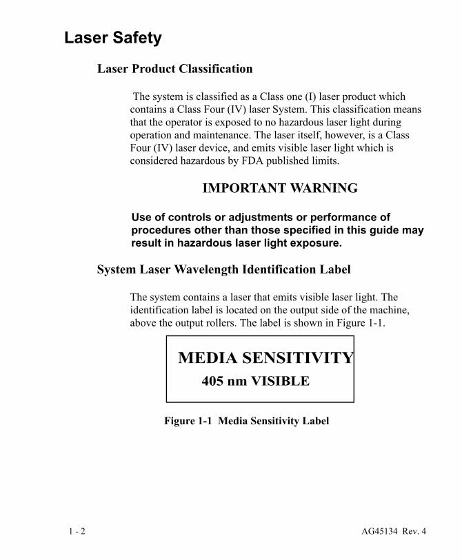
Laser Safety
Laser Product Classification
The system is classified as a Class one (I) laser product which contains a Class Four (IV) laser System. This classification means that the operator is exposed to no hazardous laser light during operation and maintenance. The laser itself, however, is a Class Four (IV) laser device, and emits visible laser light which is considered hazardous by FDA published limits.
IMPORTANT WARNING
Use of controls or adjustments or performance of procedures other than those specified in this guide may result in hazardous laser light exposure.
System Laser Wavelength Identification Label
The system contains a laser that emits visible laser light. The identification label is located on the output side of the machine, above the output rollers. The label is shown in Figure 1-1.
Figure 1-1 Media Sensitivity Label
MEDIA SENSITIVITY405 nm VISIBLE
1 - 2 AG45134 Rev. 4
Regulatory Information
Electromagnetic Emissions
DOC - Canada
The Canadian Department of Communications requires compliance with the Radio Interference Regulations, ICES -003.
This digital apparatus does not exceed the Class A limits for radio noise emissions from digital apparatus set out in the Radio Interference Regulations of the Canadian Department of Communications.
EMC Directive - Europe
Complies with EN 55011: 1998
This is a Class A product. In a domestic environment this product may cause radio interference in which case the user may be required to take adequate measures.
FCC - USA
The standards for electromagnetic emissions are Part 15, Subpart J of the FCC rules. The system was tested to Class A limits. The following statements are required by the FCC:
Changes or modifications to this unit not expressly approved by the party responsible for compliance could void your authority to operate the equipment.
This equipment has been tested and found to comply with the limits for a Class A digital device, pursuant to Part 15 of the FCC Rules. These limits are designed to provide reasonable protection against harmful interference when the equipment is operated in a commercial environment. This equipment generates, uses, and can radiate radio frequency energy and, if not installed and used in accordance with the instruction guide, may cause harmful interference to radio communications. Operation of this equipment in a residential area is likely to cause harmful interference in which
AG45134 Rev. 4 1 - 3
case the user will be required to correct the interference at his or her own expense.
Compliance with applicable regulations depends on the use of shielded cables. It is the user who is responsible for procuring the appropriate cables.
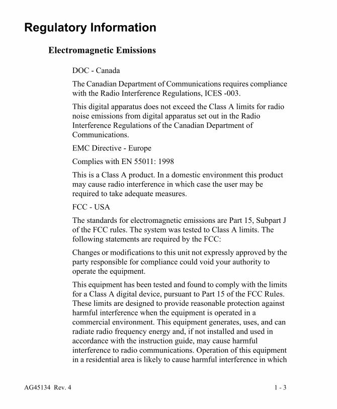
Identification and Certification Label (ratings plate)
The identification and certification label is attached to the back, exterior of the unit, above the pinch rollers.
Figure 1-1 Identification and Certification Label
1 - 4 AG45134 Rev. 4
2 System OperationIntroduction
A complete Mako 4 system includes a control workstation, CtServer software, a power conditioner, and a Mako 4 platesetter.
Workstation
The control workstation connects directly to the platesetter and runs the CtServer software. Operating instructions for the workstation are provided with the workstation.
The operator makes frequent use of the workstation when running the platesetter. For that reason, the workstation should be set up and operated next to the platesetter.
CtServer Software
CtServer is used to send jobs to the platesetter. It is also used to define the plate and pin bar requirements for jobs and communicate that information to the platesetter, which displays the information on the control panel LCD.
The use and operation of CtServer is documented in the CtServer User’s Guide, which is delivered as a PDF document on the CtServer CD.
Power Conditioner
The power conditioner shields the system from as ac power spikes, voltage drops, and other electrical power disturbances.
AG45134 Rev. 4 2 - 1

Platesetter
The platesetter outputs the imaged plates.
Main Parts of the Platesetter
Figure 2-1 Main Parts of the Platesetter
The Power Switch
The power switch controls ac power to the system. To start up the system, turn on the power switch located on the rear right side of the machine. Depress zero (0) to turn OFF, depress one (1) to turn ON. See Figure 1-1.
Note: It is recommended that the system be powered on for a 1-hour warm-up period prior to imaging.
FRONT VIEW
POWER SWITCH
CONTROL PANEL
PINCH ROLLER BAR
MEDIA TRANSPORT
REAR VIEW
INPUT TRAY
PEDESTAL
PIN BAR
FANFILTER FAN
FILTERPOWER CORD
2 - 2 AG45134 Rev. 4

The Power Cord
The power cord plugs into a receptacle located just below the power switch.
Note: In order for the system to work properly, the platesetter, the CtServer computer, and the computer monitor must all be plugged into the system power conditioner. Be advised that if the devices are not plugged into the power condi-tioner, damage resulting from voltage spikes, brownouts, etc., will NOT be covered by the warranty.
The Pin Bar
The pin bar is used for plate registration. There are two types of pin bars: press notch registered and edge registered. Two pin bars come with the system as standard equipment. Additional pin bars can be ordered as an option. Exposing sets of plates with different registration notch requirements is easily accomplished by changing the pin bar.
The Control Panel
The control panel allows you to interact with the platesetter. Commands and options are controlled through this device.
PREV NEXT
MENU SELECT
LCD
OK
CANCEL
keypad
EXPOSE ERRORATTENTIONLEDs
Figure 2-2 Control Panel
AG45134 Rev. 4 2 - 3

The Input Tray
The input tray is used to position the plate for exposing. The plate is placed on the input tray and gently slid to engage the registration pins. A groove is provided in the surface of the input tray to provide a convenient place to push the plate forward. A plate cannot be loaded until the previous plate has been completed.
The Pinch Roller Bar
The pinch roller bar is used to open and close the pinch rollers. These high precision rollers control the plate during exposing. The pinch roller bar must be up (pinch rollers open) to load a plate and down (pinch rollers closed) to expose a plate.
Never raise the pinch roller bar while a plate is being exposed! Doing so will cause the plate to jam inside the platesetter if you are using an edge-registered pin bar.
Note: The pinch roller bar must be up during the initialization process after a power on.
Figure 2-3 Pinch Rollers
PINCH ROLLER BAR *
PINCH ROLLERS
* SHOWN IN THE UP (OPEN) POSITION
2 - 4 AG45134 Rev. 4

Fan Filters
The system uses 2 fan filters. The filters slide into slots on either side of the unit (see Figure 2-1).
The Media Transport
The media transport provides for automated delivery of media to a customer-supplied online processor.
The Pedestal
The pedestal is a specially designed base for the platesetter.
Starting Up the SystemTurn on the power switch located on the rear right side of the machine. Depress one (1) to turn the power ON. When the system completes its initialization, a message appears on the display indicating ONLINE. When ONLINE appears, the host computer can be powered on. Once the host computer is powered on and running CtServer or the RIP, and the Mako CTP is ONLINE, the system is ready to expose images.
Note: It is recommended that the system be powered on for a 1-hour warm-up period prior to imaging.
Shutting Down the SystemTo shut down the system, turn off the power switch located on the lower right side of the machine. Depress zero (0) to turn the power OFF. Shut down the system only when the display reads ONLINE, and the second line is blank. (No operational message visible). Once the machine is turned off, the host computer will have to be rebooted after the machine is turned back on in order to establish communication.
AG45134 Rev. 4 2 - 5

Using the Control PanelWhen you first install the system, you must review and set all the menu parameters. Advance through the menu items and verify or change them as needed. When the menu parameters are completed, the system is ready for use.
Accessing Menus
Access menus from the system control panel. Enter the menu sub-system by pressing MENU from the ONLINE state.
Figure 2-4 Control Panel
PREV NEXT
MENU SELECT
LCD
OK
CANCEL
KEYPAD
EXPOSE ERRORATTENTIONLEDS
2 - 6 AG45134 Rev. 4

Keys
Moves you backward within the menu or moves the cursor backward within the current menu item.
Enter or exit the menu sub-system by pressing MENU from the ONLINE state.
Moves you forward within the menu or moves the cursor forward within the current menu item.
Increments the numeric digit under which the cursor is positioned or scrolls through the options available for the current menu item.
Start exposing the loaded plate. Also, from anywhere in a numeric field, causes the next menu item to be displayed. In the last item of a menu, causes a return to the first item
of the menu.
Cancels a pending “load plate” request, but does not stop a job that is in progress.
The Emergency stop button. This button will stop all moving parts of the platesetter.
LEDs
Green LED that indicates the plate is being exposed when it is flashing. Additionally, indicates registration pin contact when loading a plate.
Yellow LED that indicates there is a condition that requires operator attention. The LCD display indicates what needs to be done.
Red LED that indicates a platesetter error condition. The LCD display indicates what the error is.
PREV
MENU
NEXT
SELECT
OK
CANCEL
EXPOSE
ATTENTION
ERROR
AG45134 Rev. 4 2 - 7
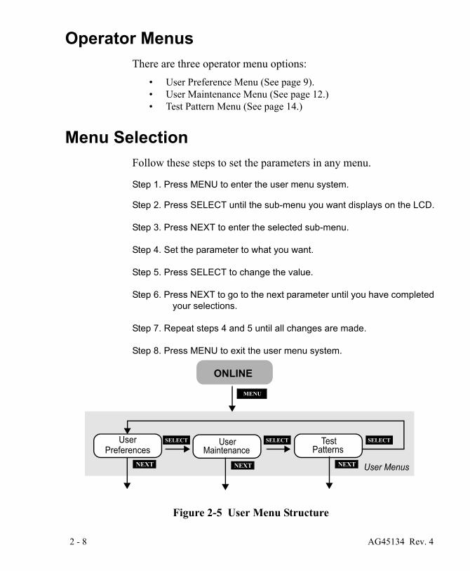
Operator MenusThere are three operator menu options:
• User Preference Menu (See page 9).• User Maintenance Menu (See page 12.)• Test Pattern Menu (See page 14.)
Menu Selection Follow these steps to set the parameters in any menu.
Step 1. Press MENU to enter the user menu system.
Step 2. Press SELECT until the sub-menu you want displays on the LCD.
Step 3. Press NEXT to enter the selected sub-menu.
Step 4. Set the parameter to what you want.
Step 5. Press SELECT to change the value.
Step 6. Press NEXT to go to the next parameter until you have completed your selections.
Step 7. Repeat steps 4 and 5 until all changes are made.
Step 8. Press MENU to exit the user menu system.
Figure 2-5 User Menu Structure
PreferencesTest
PatternsSELECT
NEXT
UserPreferences
UserMaintenance
Test Patterns
TestPatterns
SELECT SELECT
ONLINE
MENU
User Menus NEXT NEXT
2 - 8 AG45134 Rev. 4

User Preferences MenuUNITS OF MEASURE
OPTIONS ENGLISH (inches) or METRIC (millime-ters)
The selected units of measure apply to all numeric measurement values in various menus.
AUDIO ALERTS
OPTIONS ENABLED or DISABLED
This menu item allows you to disable or to enable the audible alarms for the following conditions:
Error conditions, Power-up, Image complete
HORIZONTAL MAGNIFICATION
LIMITS 85.00% to 110.00%
Sets the size of the image in the horizontal direction from 85% to 110% of nominal.
VERTICAL MAGNIFICATION
LIMITS 85.00% to 110.00%
Sets the size of the image in the vertical direction from 85% to 110% of nominal.
AG45134 Rev. 4 2 - 9

Figure 2-6 User Preferences Menu Map
NEXT
Units of
Audio Alerts
User Preferences Menu
Measure
Horizontal
Vertical
Image
Magnification
Magnification
Offset
NEXT
NEXT
NEXT
Ignore LaserTemp. Errors
NEXT
Ignore TheProcessor
NEXT
ProcessorSpeed
NEXT
NEXT
PreferencesTest
PatternsSELECT
NEXT
UserPreferences
UserMaintenance
Test Patterns
TestPatterns
SELECT SELECT
ONLINE
MENU
User Menus
OverlapOutputting &
Imaging
PREV NEXT
MENU SELECT
OK
CANCEL
EXPOSE ERRORATTENTION
2 - 10 AG45134 Rev. 4

IMAGE OFFSET
LIMITS -0.300” to +0.300” (-7.62mm to +7.62mm)
The image may be shifted to the left with a negative (-) value, or to the right with a positive (+) value by up to 0.300 inches. Press PREV to access the (+) and (-) sign.
IGNORE LASER TEMPERATURE ERRORS
OPTIONS YES or NO
If the laser exceeds its target operating temperature an error will be reported. It is recommended that this problem be fixed. However, if critical jobs need to be completed, it is possible to operate the laser at a higher temperature. This operation is enabled by ignoring the laser temperature errors.
Note: Operating the laser at a higher temperature shortens the life of the laser.
OVERLAP OUTPUTTING AND IMAGING
OPTIONS YES or NO
If this option is set “YES,” an operator can begin imaging another plate while the previous plate is feeding into the processor.
IGNORE THE PROCESSOR
OPTIONS YES or NO
“YES” disables the media transport conveyor and effectively makes the transport function as an output tray.
Note: This feature is useful when the online processor is down for maintenance or repairs.
PROCESSOR SPEED
LIMITS 9.5” per minute to 77.9” (241 mm/min. to 1980 mm)
Should be set to match the speed of the online processor.
AG45134 Rev. 4 2 - 11

User Maintenance MenuPROGRAM VERSIONS
This user maintenance option displays version numbers of the installed software and firmware. The versions will be displayed as:
VERSIONS JP0020 n.n JA1126 n
“NEXT” TO CONTINUE
Where JP0020 n.n is the part number and revision level of the controller software, and JA1126 n is the part number and revision level of the controller firmware.
RUN TRANSPORT
This user maintenance option will run the media transport until the STOP button is pressed. This function is used to clean the transport.
RUN MEDIA ROLLERS
This user maintenance option will run the media rollers until the STOP button is pressed. This function is used to clean the rollers.
DISPLAY ERROR LOG
This user maintenance option presents system faults (up to a maximum of 20 faults) in chronological order. TIME is the elapsed time since the latest power on. SESSION # is the total number of times the system has been turned on. DEVICE NAME identifies the system component that failed. ERROR is an indication of the nature of the fault.
DISPLAY LASER LOG
This user maintenance option presents status information about the system laser. The information is useful to service personnel,
2 - 12 AG45134 Rev. 4

who sometime request the information over the phone during service calls.
Figure 2-7 User Maintenance Menu Map
User SELECT
MENU
User Menus
User Maintenance Menu
Program
Run
Version
Run
Display
Media Rollers
Error Log
Transport
MENU
DisplayLaser Log
PreferencesUser
MaintenanceSELECTSELECT
NEXT
Test Patterns
TestPatterns
SELECT
SELECT
SELECT
SELECT
SELECT
ONLINE
ONLINE
PREV NEXT
MENU SELECT
OK
CANCEL
EXPOSE ERRORATTENTION
AG45134 Rev. 4 2 - 13
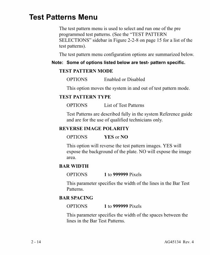
Test Patterns MenuThe test pattern menu is used to select and run one of the pre programmed test patterns. (See the “TEST PATTERN SELECTIONS” sidebar in Figure 2-2-8 on page 15 for a list of the test patterns).
The test pattern menu configuration options are summarized below.Note: Some of options listed below are test- pattern specific.
TEST PATTERN MODE
OPTIONS Enabled or Disabled
This option moves the system in and out of test pattern mode.
TEST PATTERN TYPE
OPTIONS List of Test Patterns
Test Patterns are described fully in the system Reference guide and are for the use of qualified technicians only.
REVERSE IMAGE POLARITY
OPTIONS YES or NO
This option will reverse the test pattern images. YES will expose the background of the plate. NO will expose the image area.
BAR WIDTH
OPTIONS 1 to 999999 Pixels
This parameter specifies the width of the lines in the Bar Test Patterns.
BAR SPACING
OPTIONS 1 to 999999 Pixels
This parameter specifies the width of the spaces between the lines in the Bar Test Patterns.
2 - 14 AG45134 Rev. 4

NEXT
TestPattern
SELECT
EnableSELECT
ModeDisable
NEXT
PreferencesTest
PatternsUser
PreferencesUser
MaintenanceTest
PatternsTest
Patterns
MENU
User MenusNEXT
NEXT
TEST PATTERNS
PLATE WIDTH
PLATE LENGTH
NEXT
MAGNIFICATION(HORizontal)
NEXT
NEXT
REVERSE IMAGEPOLARITY
EXPOSURE LEVEL
TEST PATTERN SELECTIONS
RUN CONTINUOUSLY
DROOP (SCOPE)DROOP (MEDIA)
CHECKERBOARD
BARS (HORIZONTAL)BARS (VERTICAL)
PRESS SELECT TO SCROLLTHROUGH THE SELECTIONOPTIONS. WHEN THE DESIRED
GRID
LASER
NEXT(SEE SIDEBAR AT RIGHT)
SELECTSELECT SELECT
Test Patterns
NEXT
NEXT
PLATE IS NOTCH REGISTERED
NEXT NOTCH DEPTH
Onl
y ap
plie
s if
“Pla
te
is N
otch
Reg
iste
red”
is
set
to Y
ES
.
ONLINE
ONLINE
NEXT
(VERtical)MAGNIFICATION
OK
STEP WEDGE
OPTION APPEARS (FOR EXAMPLE,“CHECKERBOARD”) PRESS NEXT TO SET UP PARAMETERSFOR RUNNING THAT TEST.
NEXT
DISTANCE FROMNOTCH TO
LEADING EDGE
AG45134 Rev. 4 2 - 15
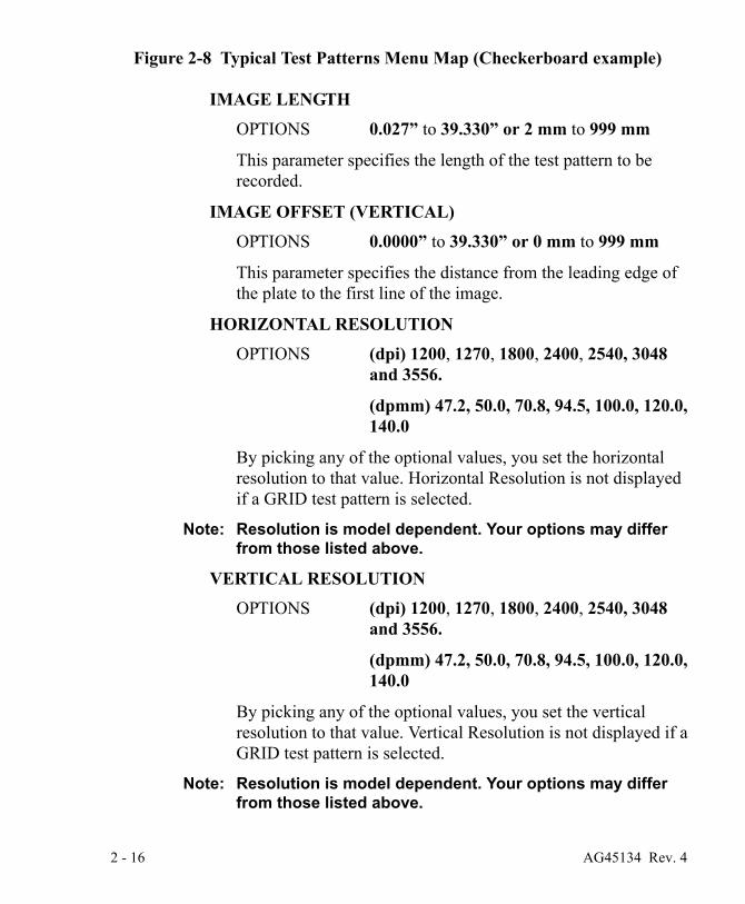
Figure 2-8 Typical Test Patterns Menu Map (Checkerboard example)
IMAGE LENGTH
OPTIONS 0.027” to 39.330” or 2 mm to 999 mm
This parameter specifies the length of the test pattern to be recorded.
IMAGE OFFSET (VERTICAL)
OPTIONS 0.0000” to 39.330” or 0 mm to 999 mm
This parameter specifies the distance from the leading edge of the plate to the first line of the image.
HORIZONTAL RESOLUTION
OPTIONS (dpi) 1200, 1270, 1800, 2400, 2540, 3048 and 3556.
(dpmm) 47.2, 50.0, 70.8, 94.5, 100.0, 120.0, 140.0
By picking any of the optional values, you set the horizontal resolution to that value. Horizontal Resolution is not displayed if a GRID test pattern is selected.
Note: Resolution is model dependent. Your options may differ from those listed above.
VERTICAL RESOLUTION
OPTIONS (dpi) 1200, 1270, 1800, 2400, 2540, 3048 and 3556.
(dpmm) 47.2, 50.0, 70.8, 94.5, 100.0, 120.0, 140.0
By picking any of the optional values, you set the vertical resolution to that value. Vertical Resolution is not displayed if a GRID test pattern is selected.
Note: Resolution is model dependent. Your options may differ from those listed above.
2 - 16 AG45134 Rev. 4

PLATE WIDTH
OPTIONS 9.922” to 25.472” or 253.8 mm to 646.9 mm
By picking a value, you set the plate width for test patterns.
PLATE LENGTH
OPTIONS 9.992” to 36.574” or 253.8 mm to 928.9 mm
By picking a value, you set the plate length for test patterns.
PLATE IS NOTCH REGISTERED
OPTIONS YES or NO
By picking a selection, you set the alignment to be used for test patterns. Punched plates are generally notch registered as opposed to edge registered.
NOTCH DEPTH
OPTIONS 0.000” to 1.000” or 00.0 mm to 25.4 mm
By picking a value, you set the notch depth for test patterns.
DISTANCE FROM NOTCH TO LEADING EDGE
OPTIONS 2.125” to 36.574” or 53.9 mm to 928.9 mm
This options specifies the distance from the leading edge of the plate to the center of the notch that is closest to the leading edge. This parameter is only for notch-registered plates.
EXPOSURE LEVEL
LIMITS 000 to 255
This menu entry sets the exposure level at the media. The higher the number, the higher the exposure.
HORIZONTAL MAGNIFICATION
AG45134 Rev. 4 2 - 17

LIMITS 85.00% to 110.00%
Sets the size of the image in the horizontal direction from 85% to 110% of nominal.
VERTICAL MAGNIFICATION
LIMITS 85.00% to 110.00%
Sets the size of the image in the vertical direction from 85% to 110% of nominal.
2 - 18 AG45134 Rev. 4

Running a Step Wedge Test PatternThe step wedge test pattern is used to set the proper exposure for apolymer plate. Here’s how to run step wedge test plate.
Preparing to Run the Step Wedge Test Pattern
Step 1. Under safelight conditions, place a test plate on the input shelf.
Step 2. Using the plate manufacturer’s recommended step wedge, cen-ter the step wedge on the plate 6 inches (15.2 cm) back from the leading edge, as shown below.
Be sure to use two pieces of tape. Make sure the emulsion side of the step wedge faces the emulsion side of the plate, and that there are no air gaps between the wedge and the plate.
Figure 2-9 Placement of Step Wedge on Test Plate
Running the Step Wedge Test
Step 1. At the control panel, press MENU and then repeatedly press SELECT until the “Test Patterns” Menu displays.
Step 2. Press NEXT, and then press SELECT to Enable.
STEP WEDGE
Centerline of Plate6 inches
TAPE
TAPE
Leading Edge of Plate
15.2 cm
AG45134 Rev. 4 2 - 19

Step 3. Press NEXT, and then repeatedly press SELECT until the Step Wedge pattern displays. Then, press NEXT again.
Step 4. Set Horizontal resolution to the required resolution.
Step 5. Set Vertical resolution to the required resolution.
Step 6. Set Exposure to the value you wish to expose the wedge (range is 0-255.)
Step 7. Set Plate Width to the plate width being used.
Step 8. Set Plate Length to the plate length being used.
Step 9. Set Magnification Horizontal to the magnification being used (nor-mally 100%).
Step 10. Set Magnification Vertical to the magnification being used (nor-mally 100%).
Step 11. Select MENU.
Step 12. Press the SELECT key to begin exposure.
The system exposes the first 8 inches of the plate with 100% laserlight at the exposure setting selected. After exposure, the plate moves into the output tray onto thetransport belt where it advances until the leading edge of theplate is detected by the transport exit sensor. The transportthen stops, the warning light flashes, and a prompt to removethe step wedge displays on the control panel.
Step 13. Making sure to maintain safelight conditions, remove the taped-on step wedge.
Step 14. At the control panel, press OK.
Step 15. If the system has the optional media transport, the transport will start again and feed the plate into the processor.
2 - 20 AG45134 Rev. 4

Status MessagesDuring operation, the system displays information that indicates the current condition of the system and of any jobs in process. The status messages appear on the control display.
PREPARING TO EXPOSE - The system is starting the spinner and moving the plate to the recording start position.
EXPOSING IMAGE - The system is now recording an image.
EJECTING PLATE - Exposing is complete and the plate is being ejected onto the plate transport.
MOVING TO PROCESSOR - Plate has been ejected from the rollers and is moving to the processor.
FEEDING PROCESSOR - Plate is on the transport and the leading edge of the plate is moving into the processor.
EJECTING PLATE - Exposing is complete and the plate is being ejected onto the plate transport.
ONLINE - The normal operating mode for the system.
STARTING SPINNER - This message is accompanied by a progress bar when preparing to start an image and the spinner motor is stopped.
TEST PATTERNS - Test Patterns mode has been selected in the Test Patterns Menu and the system is ready to produce a test pattern. This mode of operation should be used by qualified service technicians only.
INITIALIZING - The system is performing initialization functions prior to going online.
Note: If the Pinch Roller bar is down, you will be instructed to raise it during initialization.
WAITING FOR LASER - The system is waiting for the laser to reach operational temperature.
AG45134 Rev. 4 2 - 21

Error MessagesDuring operation, error conditions may occur that require your intervention. These messages will appear on the system display panel and the error indicator LED will light. Additionally, if enabled, the alarm will also sound.
Operator-Correctable Errors
The error messages that you can clear are listed below.
COVERS ARE NOT SECURE - This error is displayed when one of the system covers are not secure. Locate and close the open cover, and then
OPERATOR ABORT - This error is displayed when the operator aborts a job by using the ‘stop’ button on the control panel.
LASER IS OVER TEMPERATURE - Alerts you that the laser is over temperature. If you override this error in the User Preferences Menu, the laser life will be shortened.
IMAGE OFFSET ERROR, INCOMPATIBLE PARAMETERS - This error is displayed when the combination margin, resolution, magnification, media width, and image offset result in a condition where the image starts before the laser can activate. If you should encounter this error, minor adjustments to the above parameters, to push the image to the center of the plate should resolve the problem
PINCH LEVER OPENED WHILE MOVING MEDIA - This error is displayed if the pinch lever bar is raised while a plate is moving through the machine.
Correcting Errors
Step 1. If a plate is in the machine when the error occurs, remove the plate as explained in “Maintenance and Troubleshooting.”
Step 2. Correct the condition that caused the error.
2 - 22 AG45134 Rev. 4

Step 3. Press the control panel “OK” button.
Step 4. Resume normal operation.
System Configuration DisplayShould you ever call for service, your service provider may ask you to relate the information that appears on the System Configuration display. To view the display:
Step 1. Place the system in ONLINE mode.
Step 2. Press the Select key. The System Configuration Screen displays.
Step 3. Convey the information on the screen to your service provider.
Step 4. Press the select key to clear the display and return to ONLINE mode.
Figure 2-10 System Configuration Display
SELECT
SYSTEMCONFIGURATION
SELECT
THIS SCREEN DISPLAYS THE FOLLOWING INFORMATION ABOUT YOUR SYSTEM:
---------------------------------MACHINE TYPE
---------------------------------FIRMWARE / MACHINE ID--------------------------------
LASER POWER/SENSITIVITY/OPTICAL EFFICIENCY
---------------------------------OUTPUT TYPE / SPINNER
MOTOR---------------------------------
SERVICE PERSONNEL OFTEN REQUEST THIS INFORMATION PRIOR TO MAKING A SERVICE CALL.
ONLINE
AG45134 Rev. 4 2 - 23

2 - 24 AG45134 Rev. 4
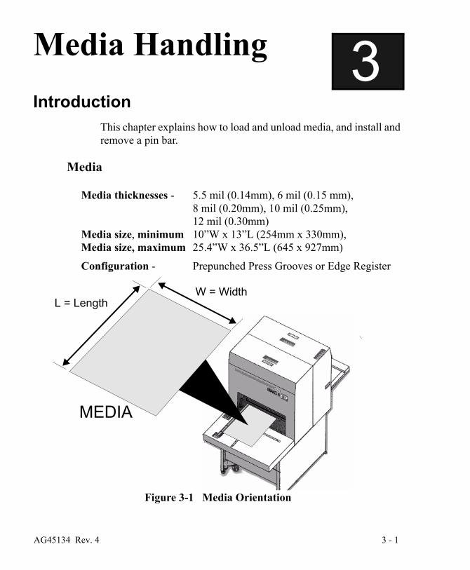
3 Media HandlingIntroduction
This chapter explains how to load and unload media, and install and remove a pin bar.
Media
Media thicknesses - 5.5 mil (0.14mm), 6 mil (0.15 mm), 8 mil (0.20mm), 10 mil (0.25mm), 12 mil (0.30mm)
Media size, minimum 10”W x 13”L (254mm x 330mm),Media size, maximum 25.4”W x 36.5”L (645 x 927mm)
Configuration - Prepunched Press Grooves or Edge Register
Figure 3-1 Media Orientation
L = LengthW = Width
MEDIA
AG45134 Rev. 4 3 - 1
Media Handling
This product is designed to be operated in a safe-light room.
• See plate manufacturer’s specification for safe-light recommenda-tions
• Safe working time varies with manufacturer
The procedure for installing the pin bar and loading the media is covered in this chapter, as well as removing the pin bar and media. This chapter is divided into the following sections.
• Installing and Removing the Pin Bar
• Loading Media
• Removing Media from the Output Tray
Mako 4 CTP does not have the ability to “know” which pin bar is loaded. It is up to you to make sure the pin bar is appropriate for the plate that is being used.
3 - 2 AG45134 Rev. 4
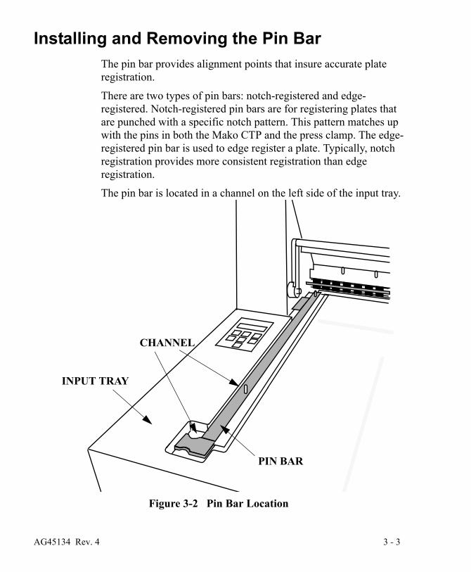
Installing and Removing the Pin BarThe pin bar provides alignment points that insure accurate plate registration.
There are two types of pin bars: notch-registered and edge-registered. Notch-registered pin bars are for registering plates that are punched with a specific notch pattern. This pattern matches up with the pins in both the Mako CTP and the press clamp. The edge-registered pin bar is used to edge register a plate. Typically, notch registration provides more consistent registration than edge registration.
The pin bar is located in a channel on the left side of the input tray.
Figure 3-2 Pin Bar Location
PIN BAR
CHANNEL
INPUT TRAY
AG45134 Rev. 4 3 - 3
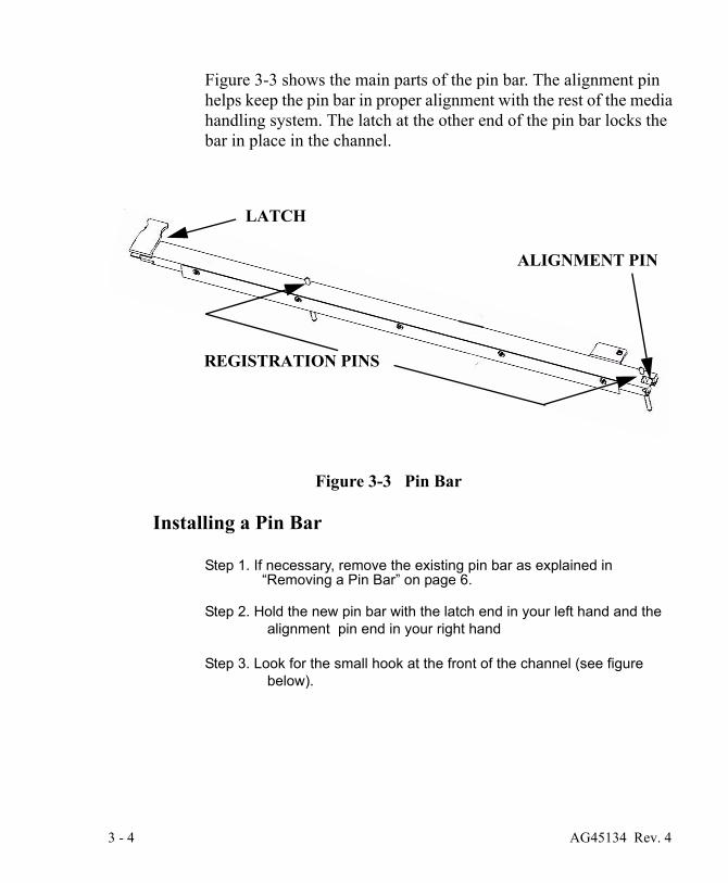
Figure 3-3 shows the main parts of the pin bar. The alignment pin helps keep the pin bar in proper alignment with the rest of the media handling system. The latch at the other end of the pin bar locks the bar in place in the channel.
Figure 3-3 Pin Bar
Installing a Pin Bar
Step 1. If necessary, remove the existing pin bar as explained in “Removing a Pin Bar” on page 6.
Step 2. Hold the new pin bar with the latch end in your left hand and the alignment pin end in your right hand
Step 3. Look for the small hook at the front of the channel (see figure below).
ALIGNMENT PIN
REGISTRATION PINS
LATCH
3 - 4 AG45134 Rev. 4

Figure 3-4 Alignment Pin Hook
Step 4. Position the pin bar over the channel with the alignment-pin end at the front of the channel and the latch at the back of the channel.
Step 5. Holding the pin bar at a 45 degree angle, snap the pin bar align-ment pin into the hook, as shown in Figure 3-5.
Step 6. Press down on the alignment pin so that it stays in the hook; then, lower the other end the pin bar into the channel until the latch snaps and locks the bar in place.
HOOK
FRONT OF
CHANNEL
AG45134 Rev. 4 3 - 5

Step 7. Firmly press the center of the pin bar down to insure that it is seated properly.
Figure 3-5 Setting the Alignment Pin in the Hook
Removing a Pin Bar
Step 1. Push the pin bar latch forward to disengage the latch.
Step 2. Lift the pin bar up by the latch until the bar is at about a 45 degree angle.
Step 3. At the front of the pin bar, disengage the alignment pin from the hook in the channel.
Step 4. Carefully remove the pin bar and store it in a safe place.
HOOK
ALIGNMENT PINBARPIN
CHANNEL
3 - 6 AG45134 Rev. 4

Loading MediaThe host computer will request a pin bar and plate to be loaded, and the Mako CTP will prompt you to load the plate. One of the following prompts appears on the control panel LCD:
LOAD A PLATE<plate name><bar name>
This message indicates that the next plate to be imaged is the same as the preceding plate. It is a prompt for you to load the same kind of plate that was just imaged.
LOAD A NEW PLATE<plate name><bar name>
This message indicates that the next plate to be imaged is different than previous plate, but that it uses the same pin bar. It is a prompt for you to load the new (different) type plate.
VERIFY BAR AND LOAD<plate name><bar name>
The meaning of this message depends on when it appears during the CtServer (host computer) session.
When the session is first opened, it is a prompt for you to ensure that the correct pin bar is installed before loading the first plate, and then to load the plate.
Subsequently in the session, the message indicates that the next plate to be imaged is different than the preceding plate AND requires a different pin bar. Thus, it is a prompt for you to change the pin bar and load the new (different) plate.
The technique used for loading plates is a key in achieving good
AG45134 Rev. 4 3 - 7

plate registration. Always handle and position the plate gently and carefully. Thin plates are especially susceptible to dings and dents.
Figure 3-6 External View of the System
Loading Edge-registered plates
Step 1. Face the front of the recorder.
FRONT VIEW
POWER SWITCH
CONTROL PANEL
PINCH ROLLER BAR
TRANSPORT
REAR VIEW
INPUT TRAYFAN FILTER
PEDESTAL
PIN BAR
3 - 8 AG45134 Rev. 4

Step 2. Raise the pinch roller bar to open the pinch rollers.
Be sure the pinch roller is fully raised. If it is not, the green Expose LED will not light.
Step 3. Verify the requested pin bar is loaded. If it is not, change the pin bar.
Step 4. Place the requested plate on the input tray.
PREV NEXT
MENU SELECT
OK
CANCEL
EXPOSE ERRORATTENTION
GREEN LED
AG45134 Rev. 4 3 - 9

Step 5. Push the plate to the left so that the edge of the plate contacts the registration pins in the pin bar. (See View A, Figure 3-7).
Figure 3-7 Loading Edge-registered Plates
Step 6. Push the plate forward (View B) into the recorder until it comes into contact with a third registration pin that is inside the recorder.
Step 7. Gently adjust the position of the plate as needed to get the green Expose LED to come on and stay on. This shows the plate is maintaining contact with all 3 registration pins (the 2 on the pin bar, plus the 1 inside the recorder).
PLATE
PIN BAR
EDGE
REGISTRATION
PINCH ROLLERS
VIEW A VIEW B
OF PLATE
PIN
3 - 10 AG45134 Rev. 4

If the LED goes out, you have lost pin contact. Move the plate out and to the right slightly, and then back in and to the left until the green LED stays on. Be careful to not apply so much pres-sure to the plate that the registration pins dent the plate. Use one finger/thumb to apply minimal pressure to the center of the plate.
Note: If the green LED is not staying illuminated, the pin bar may not be fully seated. Remove and reinstall the pin bar, following the instructions above.
Step 8. Holding the plate in position, lower the pinch roller bar . The green light will remain on if pin con-tact has been main-tained and the recorder will prompt for the OK button to be pressed to start imaging.
Note: If the green LED does not stay illuminated, open the pinch roller bar and go back to Step 5.
Step 9. Press the OK button. Imaging will begin.
CAUTION - Never raise the pinch roller bar while a plate is being exposed. Doing so will cause the plate to jam inside the platesetter. For details, refer to “Clearing Misfeeds” in the troubleshooting chapter.
Step 10. After the plate is imaged, it will be automatically transported from the Mako to the on-line processor via the media transport.
PREV NEXT
MENU SELECT
OK
CANCEL
EXPOSE ERRORATTENTION
GREEN
OK
LED
AG45134 Rev. 4 3 - 11

Loading Notch-registered plates
Step 1. Face the input tray.
Step 2. Raise the pinch roller bar to open the pinch rollers.
Be sure the pinch roller is fully raised. If it is not, the green Expose LED will not light.
Step 3. Verify the requested pin bar is loaded. If it is not, change the pin bar.
Step 4. Place the requested plate on the input tray.
Step 5. Position the plate so that both notches in the plate fully engage the two registration pins on the pin bar (see Figure 3-8).
3 - 12 AG45134 Rev. 4

Figure 3-8 Loading Notch-registered Plates.
Step 6. Watch for the green Expose LED to come on and stay on. This shows the plate is maintaining contact with the pins.
If the LED goes out, you have lost pin contact. Move the plate slightly away from the registration pins and then back against
PLATE
PIN BAR
REGISTRATION PIN
PINCH ROLLERS
REGISTRATION PIN
NOTCH
PIN BAR
AG45134 Rev. 4 3 - 13

them again until the green LED stays on.Be careful to not apply so much pressure to the plate that the registration pins dent the plate. Use one finger/thumb to apply minimal pressure to the center of the plate while lifting the plate slightly.
Note: If the green LED is not staying illuminated, the pin bar may not be fully seated. Remove and reinstall the pin bar, fol-lowing the instructions above.
Step 7. Holding the plate in position, lower the pinch roller bar. The green light will remain on if pin contact has been maintained and the recorder will prompt for the OK button to be pressed to start imaging.
Note: If the green LED does not stay illuminated, open the pinch roller bar and go back to Step 5.
Step 8. Press the OK button. The plate will be backed up to properly posi-tion the leading edge for exposing.
Step 9. After the plate is imaged, it will automatically be transported out of the platesetter and into the on-line processor.
3 - 14 AG45134 Rev. 4

4 Maintenance and TroubleshootingIntroduction
This chapter discusses:
• General Maintenance
• Moving the System
General MaintenanceThis chapter explains how to keep the system in clean, working order. Remember to shut the power off to the machine prior to performing any internal maintenance procedures. Use only the recommended cleaner. Make sure that cleaning supplies are lint and dirt free.
AG45134 Rev. 4 4 - 1
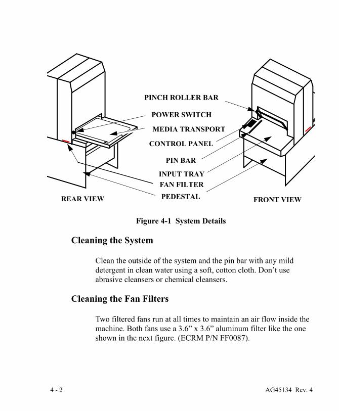
Figure 4-1 System Details
Cleaning the System
Clean the outside of the system and the pin bar with any mild detergent in clean water using a soft, cotton cloth. Don’t use abrasive cleansers or chemical cleansers.
Cleaning the Fan Filters
Two filtered fans run at all times to maintain an air flow inside the machine. Both fans use a 3.6” x 3.6” aluminum filter like the one shown in the next figure. (ECRM P/N FF0087).
FRONT VIEW
POWER SWITCH
CONTROL PANEL
PINCH ROLLER BAR
MEDIA TRANSPORT
REAR VIEW
INPUT TRAYFAN FILTERPEDESTAL
PIN BAR
4 - 2 AG45134 Rev. 4

The filters can become clogged with dust and other debris if it is not cleaned regularly. A clogged filter can result in the loss of internal pressure and increase the possibility of a system malfunction. Clean the filters whenever they show signs of contamination with dust or other debris
Here’s how to remove and replace the filters:
Step 1. Turn the power switch off.
Step 2. From inside the pedestal, reach up and under the machine where the on/off switch is located. See Figure 4-2.
Step 3. Place your fingers on the filter. It has a corrugated feel.
Step 4. Gently push the filter toward the outside of the machine until the filter protrudes from the slot shown below.
Figure 4-2 Fan Filter Removal
FAN FILTER SLOT
ON/OFF SWITCH
PEDESTAL
AG45134 Rev. 4 4 - 3

Step 5. Pull the filter out of its slot.
Step 6. Wash the filter in mild, soapy water, rinse in clean water and dry.
Step 7. Place the filter back into the slot.
Step 8. Push the filter, from the outside, until it is completely in the machine.
Step 9. From inside the pedestal, gently push the filter to the middle of the machine until it is fully seated in the holder.
Step 10. Repeat steps 1 through 10 above for the other filter, which is located on the opposite side of the system.
Cleaning the Media Drive Rollers
Cleaning the rollers will cut down on the contaminants running through the media system. Dirty rollers can cause contamination of the media.
Front Media Roller Cleaning Procedure
Cleaning the Drive Roller
Step 1. Open the pinch roller bar to open the rollers.
Step 2. Use the User Maintenance Menu to run the media rollers.
Step 3. Sparingly apply “Fantastik” (ECRM HB2456) to a clean, lint-free wipe.
Step 4. As the rollers turn, gently wipe both the front and back rollers with the cloth, being careful to not ‘catch’ the cloth in the rollers. Do not touch the rollers with bare hands. The oils and dirt will con-taminate the rollers.
Step 5. After wiping with “Fantastik,” sparingly apply isopropyl alcohol to a clean, lint-free wipe.
Step 6. As the rollers turn, gently wipe both the front and back rollers with
4 - 4 AG45134 Rev. 4

the cloth, being careful to not ‘catch’ the cloth in the rollers. Do not touch the rollers with bare hands. The oils and dirt will con-taminate the rollers.
Cleaning the Pinch Roller
Step 7. Wipe gum-contaminated pinch roller o-rings with a water-damp-ened low-lint cloth.
Step 8. If water fails to remove the gum, use ECRM PH0046 roller cleaner. (Do NOT use alcohol or a general purpose cleaner to clean the rollers.)
Step 9. Replace the covers.
Step 10. Exit the User Maintenance Menu.
Rear Media Roller Cleaning Procedure
The rear media roller is not accessible to an operator. The next time you have the system serviced, ask your service provider to clean the rear roller.
Cleaning the Media Transport Output Sensor
Step 1. Using a cotton tip swab moistened with isopropyl alcohol, gently rub the output sensor to remove any debris buildup.
Figure 4-3 Media Transport
ROLLERS
OUTPUT SENSOR
BELT
AG45134 Rev. 4 4 - 5
Cleaning the Media Transport Belt
Step 1. Use the User Maintenance Menu to run the transport.
Step 2. Using a lint-free cloth moistened with “Fantastik” (ECRM HB2456), remove debris from the belt.
Step 3. Using a second lint-free cloth moistened with alcohol, rub down the belt.
Clearing Misfeeds Two methods for clearing a misfeed are presented below.
• Use Method 1 if you are using a notch-registered pin bar.
• Use Method 2 if you are using an edge-registered pin bar.
Method 1
Step 1. Lift the pinch roller bar to open the roller.
Step 2. Carefully pull the jammed media out of the rollers.
Step 3. Press the OK button on the control panel.
Step 4. Resume normal operation.
Method 2
When an edge-registered pin bar is used, a third “internal” registration pin is activated. The location of this pin (which you can feel but not see when you load a plate) is shown in Figure 4-4. The pin moves up into the media path when the pinch roller bar is raised, and it drops below the media path when the bar is lowered.
4 - 6 AG45134 Rev. 4

Figure 4-4 Internal Registration Pin
During imaging, the pinch roller bar is down and the registration pin is below the plate’s path of travel. If a misfeed or a power failure happens to occur and the plate gets “hung up” in the machine, you are advised not to raise the pinch roller bar. Doing so will raise the registration pin. If the plate happens to be positioned over the registration pin (Figure 4-5 View B), when the pin comes up and it will bend or dent the plate.
PIN BAR
FRONT PINCH ROLLER
REARPINCH ROLLER
REGISTRATION PIN
REGISTRATION PIN
REGISTRATION PIN
INTERNAL
PLATE
NOTE
The Internal Registration Pin goes upwhen the Pinch Roller Bar is raised and goes down when the Pinch Roller Bar is lowered.
AG45134 Rev. 4 4 - 7

Figure 4-5 Plate Positions over the Registration Pin
To insure against this happening, use the following procedure to remove the plate:
Step 1. Do not raise the pinch roller bar or power off the machine.
Step 2. Use the control panel PREV and NEXT buttons as follows to extract the plate:
• Press the PREV button to effect a movement of the plate toward the front of the machine, and then press the but-ton again to stop the movement.
• Press the NEXT button to effect a movement of the plate toward the back of the machine, and then press the but-ton again to stop the movement.
Step 3. Exercise the PREV and NEXT buttons as required until the plate out all the way of the machine.
REGISTRATIONINTERNAL
PIN PLATE PLATE
VIEW A VIEW BPlate not over the pin Plate over the pin
PREV NEXT OK
ERROR
4 - 8 AG45134 Rev. 4

Step 4. Press the OK button. This turns off the blinking error light and clears the the error message from the display.
Step 5. Resume normal operation.
Moving the SystemWhen installing or moving the system, you must level the system at its new location as explained below. See Figure 4-6 for the location of the leveling feet in the pedestal.
Step 1. Unplug the power cable from the (wall) outlet. Leaving one end of the cable plugged into the Mako CTP, gently coil the power cable and store it on the shelf in the pedestal.
Step 2. Disconnect the SCSI cable from the PC attached to the Mako CTP. Leaving the SCSI cable connected to the Mako CTP, gen-tly coil the power cable and store it on the shelf in the pedestal.
Figure 4-6 Levelling Feet Location
Step 3. Retract all four levelling feet so the system rides on its wheels and place the system in its new location.
Step 4. Turn all four levelling feet of the platesetter down until they just touch the floor.
LEVELING FEET
REAR VIEW
AG45134 Rev. 4 4 - 9

Step 5. Continue to turn leveling feet until the system is level, front to back and side to side.
4 - 10 AG45134 Rev. 4


