
Stemme AG - Flugplatzstrasse F2 Nr. 7 - D-15344 Strausberg
A4011121_B21_97.doc-i/29.01.13 14:09/29.01.13 15:12 Doc. No. A40-11-121
MAINTENANCE MANUAL
Powered Sailplane STEMME S10-VT
Document Number: A40-11-121
Date of Issue: Jan. 01, 1998
This Maintenance Manual is based on the original in the German language.
Some statements required by the FAA for US-registered powered gliders are included in this Maintenance Manual. These are marked and need not necessarily be observed outside of USA.
In any case, the specific national laws and regulations are obligatory.
Druck-Info: Gesamt 153 Seiten, davon Abschn.:Seiten: 1:2, 2:3, 3:55, 4:2, 5:10, 6:13, 7:34, 8:7, 9:5, 10:1, 11:1
Airframe: Engine:
Type: STEMME S10-VT Type: ROTAX 914 F2/S1
Type Certificat: EASA.A.054 (former LBA 846) LBA - Data Sheet No.: 5006
Serial No.: 11- Engine Serial No.:
Registration:

Maintenance Manual STEMME S 10-VT Date of Issue: Jan. 01, 1998 Page iii Amendment No. 21 Date: Oct. 15, 2012
A4011121_B21_97.doc-iii/29.01.13 14:09/29.01.13 15:12 Doc. No. A40-11-121
Am. No. pages removed pages inserted
Date of
amendment
Date of
insertion Signature
11 iii, iv, 4-1, 4-2, 4-3 iii, iv, 4-1, 4-2, 4-3 27.01.2003
12 iii, iv, 4-1, 4-2, 4-3 iii, iv, 4-1, 4-2, 4-3 16.03.2005
13 iii, iv, v, 4-1..4-3, 5-8, 9-1.1, 9-1.2, 9-2..9-4
iii, iv, v, 4-1..4-3, 5-8, 9-1.1, 9-1.2, 9-2..9-4
25.05.2005
14 i, iii..v, viii, 1-1, 3-17, 3-19..3-21, 3-37, 3-38, 3-40, 4-1..4-3, 5-2, 6-9, 6-13, 7-9..7-17, 7-23, 7-32, 10-1, Annex E
i, iii..v, viii, 1-1, 3-17, 3-19..3-21, 3-37, 3-38, 3-40, 4-1..4-3, 5-2, 6-9, 6-13, 7-9..7-17, 7-23, 7-32, 10-1, Annex E
30.11.2007
15 iii..vi, 1-2, 4-1..4-3 iii..vi, 1-2, 4-1..4-3 30.11.2008
16 iii, iv, 4-1..4-3 iii, iv, 4-1..4-3 24.02.2010
17 iii, iv, 4-1, 4-3 iii, iv, 4-1, 4-3 10.01.2011
18 iii, iv, v, vii, 5-1, 5-2, cover sheet Annex E
iii, iv, v, vii, 5-1, 5-2, cover sheet Annex E
07.06.2011
19 iii, iv, 4-1...4-3 iii, iv, 4-1...4-3 04.04.2012
20 iii, iv, 4-1…4-3, 5-5 iii, iv, 4-1…4-3, 5-5 13.08.2012
21 iii, iv, vi…viii, 4-1…4-3, 5-1…5-10
iii, iv, vi…viii, 4-1, 4-2, 5-1…5-11
15.10.2012

Maintenance Manual STEMME S 10-VT Date of Issue: Jan. 01, 1998 Page iv Amendment No. 21 Date: Oct. 15, 2012
A4011121_B21_97.doc-iv/29.01.13 14:09/29.01.13 15:12 Doc. No. A40-11-121
0.2 List of Effective Pages
This list is only valid for the Serial No. specified on title page. The list contains all amendments of the Maintenance Manual, effective until final approval of this Serial No. Amendments added later must be recorded.
Page Am. No. Date
i 14 30.11.2007
ii 10 14.12.2001
iii 21 15.10.2012
iv 21 15.10.2012
v 18 07.06.2011
vi 21 15.10.2012
vii 21 15.10.2012
viii 21 15.10.2012
1-1 14 30.11.2007
1-2 15 30.11.2008
2-1
2-2 8 11.11.1999
2-3
3-1
3-2
3-3
3-4
3-5
3-6
3-7
3-8
3-9 4 12.08.1998
3-10 4 12.08.1998
3-11
3-12
3-13
3-14 4 12.08.1998
3-15 10 14.12.2001
3-16 8 11.11.1999
3-17 14 30.11.2007
3-18
3-19 14 30.11.2007
3-20 14 30.11.2007
3-21 14 30.11.2007
3-22
3-23
3-24 8 11.11.1999
Page Am. No. Date
3-25 8 11.11.1999
3-26 8 11.11.1999
3-27 8 11.11.1999
3-28
3-29
3-30
3-31 1 18.03.1998
3-32 10 14.12.2001
3-33
3-34
3-35
3-36
3-37 14 30.11.2007
3-38 14 30.11.2007
3-39
3-40 14 30.11.2007
3-41
3-42
3-43
3-44 10 14.12.2001
3-45 10 14.12.2001
3-46
3-47
3-48
3-49
3-50 6 15.04.1999
3-51 6 15.04.1999
3-52
3-53
3-54
3-55 8 11.11.1999
4-1 21 15.10.2012
4-2 21 15.10.2012
5-1 21 15.10.2012
5-2 21 15.10.2012
5-3 21 15.10.2012
5-4 21 15.10.2012
Page Am. No. Date
5-5 21 15.10.2012
5-6 21 15.10.2012
5-7 21 15.10.2012
5-8 21 15.10.2012
5-9 21 15.10.2012
5-10 21 15.10.2012
5-11 21 15.10.2012
6-1
6-2
6-3
6-4
6-5
6-6
6-7
6-8 8 11.11.1999
6-9 14 30.11.2007
6-10
6-11
6-12
6-13 14 30.11.2007
7-1
7-2
7-3
7-4
7-5 8 11.11.1999
7-6
7-7
7-8
7-9 14 30.11.2007
7-10 14 30.11.2007
7-11 14 30.11.2007
7-12 14 30.11.2007
7-13 14 30.11.2007
7-14 14 30.11.2007
7-15 14 30.11.2007
7-16 14 30.11.2007
7-17 14 30.11.2007
Maintenance Manual STEMME S 10-VT Date of Issue: Jan. 01, 1998 Page vi
Amendment No. 21 Date: Oct. 15, 2012
A4011121_B21_97.doc-vi/29.01.13 14:09/29.01.13 15:12 Doc. No. A40-11-121
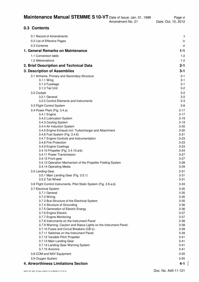
0.3 Contents
0.1 Record of Amendments ii
0.2 List of Effective Pages iv
0.3 Contents vi
1. General Remarks on Maintenance 1-1
1.1 Conversion table 1-2
1.2 Abbreviations 1-2
2. Brief Description and Technical Data 2-1
3. Description of Assemblies 3-1
3.1 Airframe, Primary and Secondary Structure 3-1
3.1.1 Wing 3-1
3.1.2 Fuselage 3-1
3.1.3 Tail Unit 3-2
3.2 Cockpit 3-2
3.2.1 General 3-2
3.2.2 Control Elements and Instruments 3-3
3.3 Flight Control System 3-8
3.4 Power Plant (Fig. 3.4.a) 3-17
3.4.1 Engine 3-17
3.4.2 Lubrication System 3-19
3.4.3 Cooling System 3-19
3.4.4 Air Induction System 3-20
3.4.5 Engine Exhaust incl. Turbocharger and Attachment 3-20
3.4.6 Fuel System (Fig. 3.4.6) 3-21
3.4.7 Engine Controls and Instrumentation 3-23
3.4.8 Fire Protection 3-23
3.4.9 Engine Cowlings 3-23
3.4.10 Propeller (Fig. 3.4.10.a/b) 3-24
3.4.11 Power Transmission 3-27
3.4.12 Front gear 3-27
3.4.13 Operation Mechanism of the Propeller Folding System 3-28
3.4.14 Operating Media 3-29
3.5 Landing Gear 3-31
3.5.1 Main Landing Gear (Fig. 3.5.1) 3-31
3.5.2 Tail Wheel 3-31
3.6 Flight Control Instruments, Pitot Static System (Fig. 3.6.a,b) 3-33
3.7 Electrical System 3-35
3.7.1 General 3-35
3.7.2 Wiring 3-35
3.7.3 Bus-Structure of the Electrical System 3-35
3.7.4 Structure of Grounding 3-36
3.7.5 Generation of Electric Energy 3-36
3.7.6 Engine Electric 3-37
3.7.7 Engine Monitoring 3-37
3.7.8 Instruments on the Instrument Panel 3-38
3.7.9 Warning, Caution and Status Lights on the Instrument Panel: 3-38
3.7.10 Fuses and Circuit Breakers (CB´s): 3-39
3.7.11 Switches on the Instrument Panel: 3-39
3.7.12 Variable Pitch Propeller 3-41
3.7.13 Main Landing Gear 3-41
3.7.14 Landing Gear Warning System 3-41
3.7.15 Avionics 3-41
3.8 COM and NAV Equipment 3-55
3.9 Oxygen System 3-55
4. Airworthiness Limitations Section 4-1

Maintenance Manual STEMME S 10-VT Date of Issue: Jan. 01, 1998 Page vii
Amendment No. 21 Date: Oct 15, 2012
A4011121_B21_97.doc-vii/29.01.13 14:09/29.01.13 15:12 Doc. No. A40-11-121
5. Inspections 5-1
5.1 Life-Limited Components 5-1
5.2 Pre-Flight Inspections 5-1
5.3 Periodical Inspections 5-1
5.3.1 Inspection Intervals 5-1
5.3.2 Additional Calendar related Inspections 5-2
5.3.3 Unscheduled Maintenance 5-2
5.3.4 Type 3 Inspection 5-3
5.3.5 General Remarks on Maintenance 5-3
5.4 Check List for Periodical Inspections 5-4
5.4.1 General 5-4
5.4.2 Wings and Fuel System Components in the Central Wing 5-4
5.4.3 Front Fuselage 5-5
5.4.4 Cockpit 5-5
5.4.5 Centre Fuselage (except for fairings) 5-5
5.4.6 Tail Boom 5-5
5.4.7 Empennage 5-6
5.4.8 Fuel System Components in the Fuselage 5-6
5.4.9 Engine and Engine Mountings 5-6
5.4.10 Lubrication System 5-7
5.4.11 Cooling System (Liquid Cooling, Ram Air Cooling, Ventilator) 5-7
5.4.12 Air Induction System 5-7
5.4.13 Engine Controls & Monitoring 5-8
5.4.14 Centre Fuselage Fairing, Engine Cowlings and Fire-Wall 5-8
5.4.15 Propeller 5-8
5.4.16 Drive Shaft with Front Gear 5-9
5.4.17 Main Landing Gear 5-9
5.4.18 Tail Wheel 5-10
5.4.19 Flight Instrumentation and Pressure Systems 5-10
5.4.20 Electric System (except for engine and TCU) 5-10
5.4.21 COM and NAV Equipment 5-10
5.4.22 Oxygen Equipment 5-10
5.4.23 Completition works 5-10
5.5 Special Inspections 5-11
5.5.1 Inspection Following a Heavy Landing or a Wing Tip Landing 5-11
5.5.2 Inspection Following an Impact to the Rotating Propeller 5-11
6. Maintenance Instructions, Tolerances, Adjustment Data for the Aircraft 6-1
6.1 General Remarks 6-1
6.2 Towing on ground, Jack Points and Lifting 6-1
6.3 Determination of Empty Weight and Corresponding Centre-of-Gravity; Weight Limits 6-2
6.4 Flight Control System 6-7
6.4.1 Deflection of Control Surfaces, Control System Friction, and Control Forces 6-7
6.4.2 Masses and Moments of Control Surfaces 6-8
6.4.3 Free Play in Flight Control System 6-8
6.5 Lubrication 6-9
6.5.1 General Remarks 6-9
6.5.2 Lubrication Plan 6-10
6.6 Surface of Composite Structures 6-11
6.7 Drainage and Ventilation Holes 6-12
6.8 Tightening Torques of Screwed Joints: 6-13
7. Maintenance Instructions, Tolerances and Adjustment Data for Assemblies / Equipment 7-1
7.1 Airframe 7-1
7.1.1 Wing 7-1
7.1.2 Fuselage 7-2
7.1.3 Empennage 7-3

Maintenance Manual STEMME S 10-VT Date of Issue: Jan. 01, 1998 Page viii
Amendment No. 21 Date: Oct. 15, 2012
A4011121_B21_97.doc-viii/04.03.13 10:48/04.03.13 10:48 Doc. No. A40-11-121
7.2 Cockpit 7-5
7.2.1 Canopy 7-5
7.2.2 Equipment and Systems 7-6
7.3 Controls 7-7
7.3.1 Controls in Fuselage 7-7
7.3.2 Controls in the Wing 7-7
7.3.3 Controls in Tail Cone/Vertical Tail 7-8
7.3.4 Deflection of Control Surfaces, Control System Friction, Control Forces 7-8
7.3.5 Slackness of Control System Bearings 7-8
7.4 Powerplant 7-9
7.4.1 Engine 7-9
7.4.2 Lubrication System 7-12
7.4.3 Cooling System 7-12
7.4.4 Air Induction System 7-13
7.4.5 Exhaust System 7-14
7.4.6 Fuel System 7-15
7.4.7 Engine Controls / Monitoring 7-16
7.4.8 Fire Protection 7-17
7.4.9 Cowlings 7-18
7.4.10 Propeller 7-19
7.4.11 Drive Shaft System 7-23
7.4.12 Front Gear, Mounting and Support 7-24
7.4.13 Propeller operation 7-25
7.5 Landing Gear 7-26
7.5.1 Main Landing Gear 7-26
7.5.2 Tailwheel 7-30
7.6 Flight Control Instruments and Pitot and Static Pressure System 7-31
7.6.1 Calibration of Stall Warning System: 7-31
7.6.2 Maintenance on the Static Pressure System 7-31
7.7 Electrical System 7-32
7.7.1 General 7-32
7.7.2 Batteries 7-32
7.7.3 Grounding 7-32
7.7.4 E-Box 7-32
7.8 Communication and Navigation Equipment 7-33
7.9 Oxygen Equipment 7-33
8. List of Placards and their Positions 8-1
9. Equipment 9-1
9.1 Minimum Equipment List 9-1
9.2 Supplementary Equipment 9-2
9.3 Additional Equipment and Systems 9-2
9.3.1 Additional Equipment 9-2
9.3.2 Optional Systems 9-4
10. List of Special Tools 10-1
11. List of Maintenance Documents for Parts Being Approved Independently from the Aircraft. 11-1
Annex A: Supplementary Instructions for Maintenance and Care, Maintenance
Instructions Annex B: Service Bulletins, Airworthiness Directives Annex C: Documents (Inspection and Operation Reports) Annex D: Maintenance and Inspection Forms. Annex E: Maintenance Manual (Line Maintenance) for ROTAX Engine Type 914
Series

Maintenance Manual STEMME S 10-VT Date of Issue: Jan. 01, 1998 Page 5-1
Amendment No. 21 Date: Oct. 15, 2012
A4011121_B21_97.doc-5-1/29.01.13 14:09/29.01.13 15:12 Doc. No. A40-11-121
5. Time Limits / Maintenance Checks
Inspections, preventive maintenance work and repairs must be carried out by qualified personnel. In any case, the specific national laws and regulations are obligatory.
In the USA, the provisions of FAR 43 must be observed. After the Annual Inspection, the aircraft must be approved for return to service by a person who is authorised according to FAR 43 and 65. Major repairs, major alterations and rebuilding (as provided by FAR 43) must be performed and approved for return to service by appropriately rated mechanics or maintenance organisations.
5.1 Life-limited components
For Life limited parts refer to the Airworthiness Limitations section of the manufacturer documentation (applicable Maintenance Manual, Service Bulletin etc.) for permissible service life limits prescribed by the respective manufacturer. These items must be entered in the form Review of Operating times.
5.2 Pre-Flight Inspections
Procedures for rigging, fuelling, daily inspection and pre-flight inspection are defined in the Flight Manual, Doc. No. A40-11-112, sections 4.2 through 4.4. Refer to Flight Manual.
5.3 Periodical Inspections
5.3.1 Inspection Intervals
The intervals for general maintenance depend on operating conditions, climate, hangarage, etc. The types and intervals of the minimum scheduled maintenance established for the S10-VT are indicated in the following table.
In USA, a distinction must be made between aircraft operated privately and those operated commercially, to comply with FAR pt. 91.409 and FAR pt. 43.
Type 1: after first 25 engine operating hours or 100 flight hours, whichever applies first.
Type 2: (In USA: not applicable if the a/c is operated commercially)
Type 2.a: every 100 flight hours
Type 2.b: additionally to the 2.a inspection, every 100 engine operating hours
Type 2.c: additionally to the 2.a and 2.b inspection, every 200 engine operating hours
Type 2.d: additionally to the 2.a, 2.b and 2.c inspection, every 600 engine operating hours
Type 3: In USA: annually and every 100 flight hours if the a/c is operated commercially
CAUTION: In USA: The scheduled maintenance type 2 is not applicable, if the a/c is operated commercially. In this case, in order to comply with FAR pt. 91.409 and FAR pt. 43, the type 3 inspection must be performed every 100 flight hours, regardless of the engine operating time.
However, to allow for some preventive maintenance items included in inspections type 2.c for 200 and 2.d for 600 engine operating hours, respectively, which are not necessarily included in the type 3 inspection program for annual or 100 flight hours, conditional items have been established
in the check list for type 3 inspections. These items are marked by "⊗" and apply to a/c not being subject to type 2 inspections, if the engine operating time requires inspection after 200 or 600 operating hours, respectively.
Even though the operator can decide at each 100 flight hour inspection type 2.a, whether or not the engine hour related inspections (2.b, 2.c and 2.d, respectively) shall be performed simultaneously, the manufacturer recommends simultaneous inspection provided the flight/engine hour ratio is less than 2:1.

Maintenance Manual STEMME S 10-VT Date of Issue: Jan. 01, 1998 Page 5-2
Amendment No. 21 Date: Oct. 15, 2012
A4011121_B21_97.doc-5-2/29.01.13 14:09/29.01.13 15:12 Doc. No. A40-11-121
Basically, any 100 hour inspection (flight or engine hours) may be exceeded by not more than 10 hours while enroute to reach a place where the inspection can be done. The excess time must be included in computing the next 100 hours of time in service.
A scheduled maintenance task may be performed before having reached the hour limit if operational requirements necessitate this. In this case it must be observed, that all higher level inspections also have to be advanced by the same time to avoid enlarged intervals.
If the first 100 flight hours are attained before the first 25 engine hours, in any case the more extensive scheduled maintenance type 1 must be performed. In this case the first type 2 inspection applies after 200 flight hours.
The items to be checked are given in section 5.4 "Check List for Periodical Inspections". A detailed description of maintenance procedures, adjustment data, tolerances etc. may be found in section 6 (for details of the complete aircraft) and section 7 (for specific assemblies). The relevant subsection is indicated in each inspection item.
In addition, special inspections which may be prescribed by the manufacturer or by the Airworthiness Authority must be performed in accordance with the issued directives. For instructions relevant to maintenance of equipment installed refer to Annex A, "Supplementary Instructions for Maintenance and Care, Maintenance Instructions".
The inspection list in section 5.4 for periodical checks covers the complete a/c including propeller and engine and substitutes for Section 05-20 (“Maintenance Schedule”) of the "Maintenance Manual (Line Maintenance) for ROTAX Engine Type 914 Series” (Annex E). The latter section of the original ROTAX Maintenance Manual needs not be observed during maintenance.
5.3.2 Additional Calendar related Inspections
5 year Inspection
After 5 years the Fuel check valves – Plastic have to be checked visually. Indications of a brittleness or change of the original colour must be specially observed. The parts must be untimely replaced if such an indication is found. After 10 years the Fuel check valves – Plastic have to be replaced (refer to section 4).
5.3.3 Unscheduled Maintenance
In addition to scheduled maintenance described above, manufacturers or authorities may require special inspections and additional measures, e. g. if incidents are known. Normally, they are made public by a SB (Service Bulletin of a/c manufacturer or manufacturer of equipment) or AD (Advisory Directive published by the authority) including a deadline for accomplishment. SB and AD are mandatory, and in case of an AD, the Certificate of Airworthiness of the a/c expires if the required corrective action is not performed as instructed prior to the given deadline.
Unscheduled Maintenance for propeller assembly, engine drive section and reduction gear components:
An unscheduled overhaul or replacement additional to expiration of the stated time limit is necessary in each case of:
• Impact stop (possible ground touch of the propeller);
• Non- observance of the periodical inspections as they are fixed in the Maintenance Manual,
In case of damaging by ground contact, bird strike, stone strike or similar which require a „large repair“, the manufacturer decides which parts of the complete drive system are affected and if a repair may be practicable or if an overhaul or replacement has to be performed.

Maintenance Manual STEMME S 10-VT Date of Issue: Jan. 01, 1998 Page 5-3
Amendment No. 21 Date: Oct. 15, 2012
A4011121_B21_97.doc-5-3/29.01.13 14:09/29.01.13 15:12 Doc. No. A40-11-121
5.3.4 Type 3 Inspection
Inspections must be performed by a licensed inspector according to the national legal regulations. In USA, FAR pt. 91.409 requires both 100 h
1) and Type 3 Inspection to be in accordance with FAR pt. 43. The type 3
inspection program includes all issues provided by FAR 43 pt. 43 Annex D.
1)in case of commercial use of the a/c
5.3.5 General Remarks on Maintenance
• Any screws and nuts have to be clean. If a screw connection is disconnected, seats and course of thread must be checked for damage and replaced if necessary.
• Self-locking nuts, disconnected once, must be renewed.
• Observe tightening torques:
- for the airframe refer to Maintenance Manual section 6.8,
- for the engine refer to "Maintenance Manual (Line Maintenance) for ROTAX Engine Type 914 Series” (Annex E) and "Maintenance Manual (Heavy Maintenance) for ROTAX Engine Types ROTAX 912 and 914 Series”
• Renew used gaskets, washers, lock rings, O-rings and shaft seals at re-assembly
• Condition of electrical wires: Checking of condition of electrical wires always includes inspection for chafing, decay of insulation material and wear of terminals or connection to terminals. In case of any deficiency the wire must be renewed, or at least repaired if only the terminal is affected. Investigate and eliminate the cause of defect.
• Condition of flexible hoses: Checking of condition of flexible hoses always includes check for chafing, leakage, decay due to thermal or chemical effects and damage of connections (specially for cracks at clamps). In case of any deficiency the hose should be renewed. Investigate and eliminate cause of defect.
WARNING: Prior to any maintenance work switch OFF Master Switch and Ignition!

Maintenance Manual STEMME S 10-VT Date of Issue: Jan. 01, 1998 Page 5-4
Amendment Nr. 21 Date: Oct. 15, 2012
A4011121_B21_97.doc-5-4/29.01.13 14:09/29.01.13 15:12 Doc. No. A40-11-121
5.4 Check List for Periodical Inspections
NOTE: Read maintenance instructions in sections 6 and 7 before carrying out adjustments! Additionally to maintenance instructions, these sections indicate special maintenance intervals (2 years) allowable for some items of the type 3 inspection program in the following check list.
WARNING: Prior to any maintenance work switch OFF Master Switch and Ignition!
For explanation of type of inspection refer to section 5.3.1 and 5.3.4.
Type and Subject of Inspection
Type 1
Type 2
.a
Type 2
.b
Type 2
.c
Type 2
.d
Type 3
refer to section
5.4.1 General
1. Thoroughly clean a/c and engine, remove or open all necessary inspection plates, access doors, fairings and cowlings
X X -
2. Inspect a/c surfaces and markings (specially registration and national flag), renew if necessary.
X X 6.6, 7.1
3. Check all drain and ventilation holes (see position plan section 6.7). X X X 6.7
4. Check all points of lubrication and grease if required (ref. to section 6.5) X X X 6.5
5. Check function of flight controls X X X 7.3
6. Check slackness of aileron, flap and elevator controls X X 6.4.3
7. Check control deflections, friction and forces in control system (form "Rigging Report", Annex Annex D: )
X 6.4.1
5.4.2 Wings and Fuel System Components in the Central Wing
1. Check fuel system components at spar bridge of centre wing. X X X 7.4.6
2. Check vent line outlets at end ribs of central wing X X X
3. Check function of quick-release couplings (supply lines) X X X 7.4.6
4. Clean both coarse filters. X X 7.4.6
5. Check fuel filler cap for leakage and for signs of leakage of wing tanks X X X 7.4.6
6. Check condition and backlash of wing fittings, check securing device of wing attachment bolts
X X X 7.1.1
7. Check condition of wing flaps and ailerons, check clearance between components spanwise 3 ± 0.5 mm / 0.12 ± 0.02 in. Check gap sealings and fairings on flap/aileron links.
X X 7.1.1
8. Check all control rods and supports in centre wing and wing attachment area, check unlooseable fastening of spring bolt of each quick-connector
X X X 7.3.1
9. Inspect L'Hotellier-connectors of aileron control rod according to manufacturer instructions (Annex A). Check unlooseable fastening of safety pin.
X X X 7.3.2
10. Check bell-crank levers and adjacent components of wing flaps and aileron system in wing.
X 7.3.2
11. Check swaged terminals of all control rods in wing X X 7.3
12. Check condition of airbrakes X X 7.3.2
Maintenance Manual STEMME S 10-VT Date of Issue: Jan. 01, 1998 Page 5-5
Amendment Nr. 21 Date: Oct. 15, 2012
A4011121_B21_97.doc-5-5/29.01.13 14:09/29.01.13 15:12 Doc. No. A40-11-121
Type and Subject of Inspection
Type 1
Type 2
.a
Type 2
.b
Type 2
.c
Type 2
.d
Type 3
refer to section
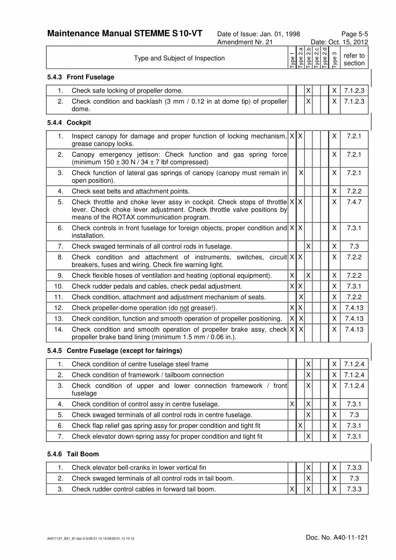
5.4.3 Front Fuselage
1. Check safe locking of propeller dome. X X 7.1.2.3
2. Check condition and backlash (3 mm / 0.12 in at dome tip) of propeller dome.
X X 7.1.2.3
5.4.4 Cockpit
1. Inspect canopy for damage and proper function of locking mechanism, grease canopy locks.
X X X 7.2.1
2. Canopy emergency jettison: Check function and gas spring force (minimum 150 ± 30 N / 34 ± 7 lbf compressed)
X 7.2.1
3. Check function of lateral gas springs of canopy (canopy must remain in open position).
X X 7.2.1
4. Check seat belts and attachment points. X 7.2.2
5. Check throttle and choke lever assy in cockpit. Check stops of throttle lever. Check choke lever adjustment. Check throttle valve positions by means of the ROTAX communication program.
X X X 7.4.7
6. Check controls in front fuselage for foreign objects, proper condition and installation.
X X X 7.3.1
7. Check swaged terminals of all control rods in fuselage. X X 7.3
8. Check condition and attachment of instruments, switches, circuit breakers, fuses and wiring. Check fire warning light.
X X X 7.2.2
9. Check flexible hoses of ventilation and heating (optional equipment). X X X 7.2.2
10. Check rudder pedals and cables, check pedal adjustment. X X X 7.3.1
11. Check condition, attachment and adjustment mechanism of seats. X X 7.2.2
12. Check propeller-dome operation (do not grease!). X X X 7.4.13
13. Check condition, function and smooth operation of propeller positioning. X X X 7.4.13
14. Check condition and smooth operation of propeller brake assy, check propeller brake band lining (minimum 1.5 mm / 0.06 in.).
X X X 7.4.13
5.4.5 Centre Fuselage (except for fairings)
1. Check condition of centre fuselage steel frame X X 7.1.2.4
2. Check condition of framework / tailboom connection X X 7.1.2.4
3. Check condition of upper and lower connection framework / front fuselage
X X 7.1.2.4
4. Check condition of control assy in centre fuselage. X X X 7.3.1
5. Check swaged terminals of all control rods in centre fuselage. X X 7.3
6. Check flap relief gas spring assy for proper condition and tight fit X X 7.3.1
7. Check elevator down-spring assy for proper condition and tight fit X X 7.3.1
5.4.6 Tail Boom
1. Check elevator bell-cranks in lower vertical fin X X 7.3.3
2. Check swaged terminals of all control rods in tail boom. X X 7.3
3. Check rudder control cables in forward tail boom. X X X 7.3.3

Maintenance Manual STEMME S 10-VT Date of Issue: Jan. 01, 1998 Page 5-6
Amendment Nr. 21 Date: Oct. 15, 2012
A4011121_B21_97.doc-5-6/29.01.13 14:09/29.01.13 15:12 Doc. No. A40-11-121
Type and Subject of Inspection
Type 1
Type 2
.a
Type 2
.b
Type 2
.c
Type 2
.d
Type 3
refer to section
5.4.7 Empennage
1. Check rudder fittings. X X X 7.1.3
2. Check connection of antenna cable (bottom of rudder). X X 7.1.3
3. Check adjustment and condition of rudder control. X X X 7.3.3
4. Check free movement of rudder, specially in case of tail wheel blockage. X X X 7.1.3
5. Check front fitting of horizontal stabiliser for spring tension, backlash of bolt, fatigue cracks and corrosion.
X X X 7.1.3
6. Check rear fitting of horizontal stabiliser for wear of pins, fatigue cracks, axial and radial backlash, corrosion.
X X X 7.1.3
7. Check tight fit of screw connections of both horizontal stabiliser fittings X X X 7.1.3
8. Check connection of elevator control rod to rear fitting of elevator. X X X 7.3.3
9. Check backlash in fittings of horizontal stabiliser when installed. X X X 7.1.3
10. Check additional battery (optional): Connections, tight fit and condition of mounting. Check if the Equipment List and Weight and Balance Report correspond with the a/c with regard to the additional battery.
X X 7.1.3
11. Check gap sealings and zigzag tape on empennage. X X 7.1.3
5.4.8 Fuel System Components in the Fuselage
1. Check quick-release couplings in supply line. X X X 7.4.6
2. Check condition of supply, return and drain lines outside the engine compartment, supply and return lines inside the engine compartment.
X X X 7.4.6
3. Check condition, attachment and function of electrical fuel pumps. X X X 7.4.6.2
4. Check fuel- cock, fuel- check- valves and drainer. Check fire- wall penetration assy of supply and return lines for tight connection and leakage.
X X X 7.4.6.2
5. Clean fine filters, check condition and change if necessary X X X 7.4.6.2
6. Change fine filter X X 7.4.6.2
7. Check drain lines of carburetor drip trays and airbox X X X 7.4.6.2
8. Check fire protective sleeves on fuel supply and return lines in engine compartment.
X X X 7.4.8.2
5.4.9 Engine and Engine Mountings
1. Engine cleaning X X X 7.4.1.3
2. Visual inspection of engine and auxiliaries X X X 7.4.1.4
3. Engine check for leakage X X X 7.4.1.5
4. Check of engine auxiliaries X X X 7.4.1.6
5. Check of waste-gate X X X 7.4.1.7
6. Check of engine gearbox X X X 7.4.1.8
7. Check magnetic plug for metal particles or foreign matter X X X 7.4.1.9
8. Check of gear wheels X X 7.4.1.10
9. Check of carburetor X X X 7.4.1.11
10. Check condition of fuel lines, pressure connection lines and compensating tube assy at carburetors and airbox
X X X 7.4.6.2
11. Check of engine wiring and cables X X X 7.4.1.12

Maintenance Manual STEMME S 10-VT Date of Issue: Jan. 01, 1998 Page 5-7
Amendment Nr. 21 Date: Oct. 15, 2012
A4011121_B21_97.doc-5-7/29.01.13 14:09/29.01.13 15:12 Doc. No. A40-11-121
Type and Subject of Inspection
Type 1
Type 2
.a
Type 2
.b
Type 2
.c
Type 2
.d
Type 3
refer to section
12. Check of V-belt tension X X X 7.4.1.13
13. Check spark plugs, renew if required. Radiator can be removed (camlocks) if required
X X 7.4.1.14
14. Check of spark plug connectors for tight fit X ⊗ 7.4.1.15
15. Check of compression pressure X X 7.4.1.16
16. Check mountings of turbocharger / muffler X X X 7.4.5.1
17. Check condition of exhaust bends (incl. attachment and springs) X X X 7.4.5.2
18. Check heat insulation (exhaust bends, muffler, heat protection shields), renew if required
X X X 7.4.5.3
19. Renew heat insulation of exhaust bends X X 7.4.5.3
20. Check of mounting points of engine housing X X X 7.4.1.18
21. Check of upper and lower engine mountings. X X X 7.4.1.18
5.4.10 Lubrication System
1. Check condition of oil radiator and oil tank assies. X X X 7.4.2.1
2. Check oil lines (engine and turbocharger) and oil drain line. X X X 7.4.2.1
3. Check condition and routing of fire protective sleeves. X X X 7.4.8.2
4. Check of oil quantity X X X 7.4.2.2
5. Change of oil. Fold up oil cooler before draining old oil. Check drain screws of oil tank and crankcase for metal particles or foreign matter.
X X X 7.4.2.3
6. Change of oil filter. Check filter insert of old filter for metal particles or foreign matter.
X X X 7.4.2.4
5.4.11 Cooling System (Liquid Cooling, Ram Air Cooling)
1. Check condition of the cooling system assies: expansion reservoir, refill container, overflow container and radiator
X X X 7.4.3
2. Check condition of coolant hoses and pipes. X X X 7.4.3
3. Rinsing of liquid cooling system X ⊗ 7.4.3
4. Renewal of coolant X ⊗ 7.4.3
5. Check of ram air cooling assy of cylinder shafts. X X X 7.4.3
5.4.12 Air Induction System
1. Check of intercooler assy. X X X 7.4.4
2. Check condition of air filter assy: Clean or change airfilter. X X X 7.4.4
3. Change of air filter X ⊗ 7.4.4
Maintenance Manual STEMME S 10-VT Date of Issue: Jan. 01, 1998 Page 5-8
Amendment Nr. 21 Date: Oct. 15, 2012
A4011121_B21_97.doc-5-8/29.01.13 14:09/29.01.13 15:12 Doc. No. A40-11-121
Type and Subject of Inspection
Type 1
Type 2
.a
Type 2
.b
Type 2
.c
Type 2
.d
Type 3
refer to section
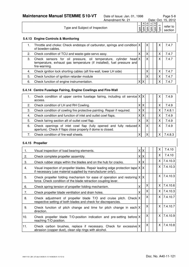
5.4.13 Engine Controls & Monitoring
1. Throttle and choke: Check endstops of carburetor, springs and condition of bowden-cables.
X X X 7.4.7
2. Check condition of TCU and waste-gate-servo assy. X X X 7.4.7
3. Check sensors for oil pressure, oil temperature, cylinder head temperature, exhaust gas temperature (if installed), fuel pressure and fire-warning.
X X X 7.4.7
4. Check ignition lock shorting cables (aft fire-wall, lower LH side) X X 7.4.7
5. Check function of ignition retarder module X X 7.4.7
6. Check function of engine instrumentation. X X X 7.4.7
5.4.14 Centre Fuselage Fairing, Engine Cowlings and Fire-Wall
1. Check condition of upper centre fuselage fairing, including oil service access.
X X X 7.4.9
2. Check condition of LH and RH Cowling. X X X 7.4.9
3. Check condition of cowling fire protective painting. Repair if required. X X X 7.4.8.1
4. Check condition and function of inlet and outlet cowl flaps. X X X 7.4.9
5. Check fairing section aft of outlet cowl flap. X X X 7.4.9
6. Check openings of inlet cowl flap (fully opened and fully reduced aperture). Check if flaps close properly if dome is closed.
X X X 7.4.9
7. Check condition of fire-wall sheets. X X X 7.4.8.3
5.4.15 Propeller
1. Visual inspection of load bearing elements. X X X 7.4.10
2. Check complete propeller assembly. X X X 7.4.10
3. Check rubber stops within the blades and on the hub for cracks. X X X 7.4.10.3
4. Visual inspection of propeller blades. Repair leading edge protection tape if necessary (use material supplied by manufacturer only!).
X X X 7.4.10.3
5. Check propeller folding mechanism for ease of operation and restoring force. Check condition of the blade retraction coupling lever.
X X X 7.4.10.3
6. Check spring tension of propeller folding mechanism. X X X 7.4.10.6
7. Check propeller blade ventilation and drain holes. X X X 7.4.10.3
8. Check adjustment of propeller blade T/O and cruise pitch. Check respective setting of both blades and check for discrepancies.
X X X 7.4.10.7
9. Check function of pitch change and time for pitch change in each direction.
X X X 7.4.10.7
10. Check propeller blade T/O-position indication and pre-setting before reaching T/O position.
X X X 7.4.10.9
11. Check carbon brushes, replace if necessary. Check for excessive abrasion (copper dust), clean slip rings with alcohol.
X X X 7.4.10.8

Maintenance Manual STEMME S 10-VT Date of Issue: Jan. 01, 1998 Page 5-9
Amendment Nr. 21 Date: Oct. 15, 2012
A4011121_B21_97.doc-5-9/29.01.13 14:09/29.01.13 15:12 Doc. No. A40-11-121
Type and Subject of Inspection
Type 1
Type 2
.a
Type 2
.b
Type 2
.c
Type 2
.d
Type 3
refer to section
5.4.16 Drive Shaft with Front Gear
1. Check noise and backlash of front gear (turn propeller by hand). X X X 7.4.12
2. Check condition of front gear suspension and attachment on front fuselage frame in shock mounts.
X X X 7.4.12
3. Check fastening and condition of lower front gear fairing. X X X 7.4.12
4. Check function of freewheel clutch. X X X 7.4.11
5. Check attachment of freewheel clutch on engine flange. X X X 7.4.11
6. Check condition and tight fit of cardanic rubber disc joint on freewheel clutch.
X X X 7.4.11
7. Check condition and tight fit of cardanic rubber disc joint on front gear. X X X 7.4.11
8. Check condition of composite shaft. X X X 7.4.11
9. Check front gear visually for condition and leakage (for inspection type 1 and 2.a with the gear installed).
X X X 7.4.12
10. Check oil quantity in front gear. X X X 7.4.12
11. Check magnetic screw of front gear X X 7.4.12
12. Change oil of front gear. X ⊗ 7.4.12
5.4.17 Main Landing Gear
1. Inspect the main landing gear legs and trailing arms for deformation and possible cracks as an result of overloads
X X X 7.5.1
2. Check the linear actuators for external damages. X X X 7.5.1
3. Check main landing gear tires for condition and creep markings. Check tire pressure: 3.2 ± 0.1 bar / 46.5 ± 1.5 p.s.i. (2.6 ± 0.1 bar / 37.7±1.5 p.s.i. if wide tire landing gear installed).
X X X 7.5.1
4. Check function of rocking arm spring suspension. X X X 7.5.1
5. Check ease of operation and backlash of wheel bearings. X X X 7.5.1
6. Check brake master cylinder and wheel cylinders, hoses and tubes X X X 7.5.1
7. Check brake discs and brake linings (at least 1.5 mm / 0.06 in.) X X 7.5.1
8. Check quantity of brake fluid X X X 7.5.1
9. Renew brake fluid (DOT 4) X ⊗ 7.5.1
10. Check brake efficiency, adjust brake if required. X X X 7.5.1
11. Check condition of gear doors. Clean and grease hinges of gear doors X X 7.5.1
12. Check free movement of doors and actuating mechanism, including bowden cable assy of LH landing gear door
X X X 7.5.1
13. Check function of landing gear (support the aircraft on trestles). Check stop switches, fit of gear doors, bowden-cables for emergency release and the release mechanism on radius strut.
X X 7.5.1
14. Check landing gear position indication and warning (optic and acoustic, during function test).
X X X 7.5.1
15. Check function of emergency gear extension. X X 7.5.1

Maintenance Manual STEMME S 10-VT Date of Issue: Jan. 01, 1998 Page 5-10
Amendment Nr. 21 Date: Oct. 15, 2012
A4011121_B21_97.doc-5-10/29.01.13 14:09/29.01.13 15:12 Doc. No. A40-11-121
Type and Subject of Inspection
Type 1
Type 2
.a
Type 2
.b
Type 2
.c
Type 2
.d
Type 3
refer to section
5.4.18 Tail Wheel
1. Tail wheel: Check ease of operation, clearance to fairing, backlash. X X X 7.5.2
2. Check tire condition, pressure 2.8 ± 0.2 bar / 41 ± 3 p.s.i X X X 7.5.2
3. Check wheel fork for cracks and deformation. X X 7.5.2
4. Check bearing of tail wheel fork. X X 7.5.2
5. Check spring coupling assy between tail wheel and rudder. X X X 7.5.2
5.4.19 Flight Instrumentation and Pressure Systems
1. Check condition of pressure system, renew filters/water separators if required.
X X X 7.6.2
2. Check condition and function - service life limits if applicable- of flight instrumentation (refer to equipment list).
X X 7.6
3. Check adjustment of stall warning. X X 7.6.1
5.4.20 Electric System (except for engine and TCU)
1. Check wiring of electric system X X X 7.7.1
2. Check condition of all electric devices installed. X X X 7.7.1
3. Check condition and function of switches. X X 7.7.1
4. Check of main battery. Observe maintenance instructions of manufacturer (refer to Annex A).
X X 7.7.2
5. Check of additional battery (optional). Observe maintenance instructions of manufacturer (refer to Annex A).
X X 7.7.2
6. Check condition of grounding. X X 7.7.3
7. Visually check electric distribution box (E-box). X X X 7.7.4
5.4.21 COM and NAV Equipment
1. Check NAV and COM equipment for proper installation and safe mounting and compare to equipment list.
X 7.8
2. Check function and, if applicable, service life limits of NAV and COM equipment (refer to records of operating times, Annex C).
X 7.8
3. Check each antenna installed X 7.8
5.4.22 Oxygen Equipment
1. Check oxygen equipment if installed. Observe maintenance instructions of manufacturer (refer to Annex A).
X X 7.9
5.4.23 Completition works
1. After end of maintenance works on the drive system - Engine check-run X X X 7.1.4.17
Maintenance Manual STEMME S 10-VT Date of Issue: Jan. 01, 1998 Page 5-11
Amendment Nr. 21 Date: Oct. 15, 2012
A4011121_B21_97.doc-5-11/29.01.13 14:09/29.01.13 15:12 Doc. No. A40-11-121
5.5 Special Inspections
5.5.1 Inspection Following a Heavy Landing or a Wing Tip Landing
Following a heavy landing or a wing tip landing, the aircraft must be inspected extensively. The inspection may be carried out by a skilled person, but, in case of obvious structural damage, by an authorised inspector with the appropriate rating. The inspection program must be requested from the manufacturer.
5.5.2 Inspection Following an Impact to the Rotating Propeller
If the rotating propeller touched the ground or other obstacles, initially an intense visual inspection is required.
In the event of minor damage to the propeller blades (e.g. shortening of a propeller blade by less than 30 mm / 1.18 in. – areas painted grey on both sides at the tips of the propeller blades are still visible – ) the following procedure should be adopted:
1. Qualified staff must establish whether the propeller blades can be repaired or not. This is not generally the case and the propeller blades have to be replaced.
2. The minimum requirement is that a type 2.b check has to be carried out on the drive system in accordance with Section 5.4.16 (in as far as it applies).
3. After the propeller blades have been repaired or replaced, the drive system must be dynamically balanced, as laid down in A17-10AP-V/2-E “Dynamic Propeller Balancing Stemme S10“ (Maintenance Manual Appendix A).
In the event of major damage to the propeller blades (e.g. shortening of a propeller blade by more than 30 mm / 1.18 in. – areas painted grey on both sides at the tips of the propeller blades are no longer visible – ) the following procedure should be adopted:
1. The propeller blades must be replaced.
2. The propeller must be inspected by the manufacturer or an authorised workshop.
3. The drive system must be inspected by the manufacturer or an authorised workshop (see Chapter 4, notes 3 and 6).
4. After an inspection has been carried out and the propeller blades have been replaced, the drive system must be dynamically balanced, as laid down in A17-10AP-V/2-E “Dynamic Propeller Balancing Stemme S10“ (Maintenance Manual Appendix A).
In contrast to other a/c, a shock-loading inspection of the engine in both events is not required because of an integrated over-load protection in the engine and the freewheel clutch as an additional safety device. Moreover the extension drive shaft system in between propeller and engine prevents the engine drive flange from bending loads in case of propeller contact with obstacles.


![7 3 Sailplane GP-1 [Mode de compatibilité]...Sailplane Grand Prix 2014 World Sailplane Grand Prix Final 2014-2015 Qualifying Sailplane Grand Prix series 2015 World Sailplane Grand](https://cdn.vdocuments.mx/doc/165x107/6023534700029d297b3d533e/7-3-sailplane-gp-1-mode-de-compatibilit-sailplane-grand-prix-2014-world.jpg)


