
1
MACHINE FOR PANDROL
"E-CLIP" FASTENING
PCMD-EC
ENGLISH OPERATION AND MAINTENANCE MANUAL
17
M 0
40
E
2
INDEX page
1. General characteristics ..................................................................................................................................................... 4
2. Unpacking ............................................................................................................................................................................. 5
2.1 Transporting the machine ............................................................................................................................................... 5
3. Description of the machine ............................................................................................................................................. 6
4. Instructions for use ............................................................................................................................................................. 8
4.1 Assembling the machine .................................................................................................................................................. 8
4.1.1 Braking device ...................................................................................................................................................................... 8
4.2 Disassembling the machine ............................................................................................................................................. 10
4.3 Moving the machine ........................................................................................................................................................... 10
4.4 Controls ................................................................................................................................................................................... 11
4.5 Preliminary machine adjustments ................................................................................................................................. 12
4.5.1 Adjusting the rear height of the machine ................................................................................................................... 12
4.5.2 Adjusting the height of the front of the machine .................................................................................................... 13
4.5.3 Adjusting the vertical alignment of the machine .................................................................................................... 13
4.6 Operation ................................................................................................................................................................................ 14
4.6.1 Inserting clips ........................................................................................................................................................................ 14
4.6.2 Extracting clips ..................................................................................................................................................................... 16
5. Display ..................................................................................................................................................................................... 17
5.1 Information screens ............................................................................................................................................................ 17
5.2 Warnings ................................................................................................................................................................................. 17
5.3 Errors ......................................................................................................................................................................................... 18
6. Starting the engine ............................................................................................................................................................. 19
7. Maintenance ......................................................................................................................................................................... 20
7.1 Routine maintenance of the machine ......................................................................................................................... 20
7.1.1 Maintenance of braking device ...................................................................................................................................... 20
7.1.2 Maintenance of clamp unit .............................................................................................................................................. 21
7.1.3 Topping up the oil in the hydraulic pump .................................................................................................................. 22
7.1.4 Replacing the hydraulic pump oil fi lter ......................................................................................................................... 22
7.1.5 Adjusting the work lights ................................................................................................................................................. 22
7.1.6 Changing the gas springs ................................................................................................................................................. 23
7.2 Routine maintenance of the engine ............................................................................................................................. 23
7.3 Long periods of inactivity ................................................................................................................................................. 23
8. Return to Cembre for overhaul .................................................................................................................................... 26

3
- Before using the machine read the instructions contained in this manual carefully.
SAVE THESE INSTRUCTIONS: this manual contains important safety and operating
instructions for the machine.
- During operation keep your hands and all other persons outside the danger area.
- Always use Personal Protective Equipment such as is normally required by your
employer and/or appropriate to your sector of operation.
- Always follow fuelling and refuelling practices and procedures normally required
by your employer and/or appropriate to your sector of operation.
- Only authorised personnel shall start, operate and maintain the machine.
- The design or confi guration of the machine shall not be modifi ed other than by
Cembre.
- Cannot be used over switches and crossings.
- Not to be used near live d.c. conductor rail.
- Not to be used for any purpose other than for which machine is designed. - Do not exceed walking pace when moving the machine along the rail.
WARNINGS

4
Application range suitable for the insertion or extraction of PANDROL* e-clip
on standard gauge sleepers (1435 mm)
Developed force (single clamp) N 30.000
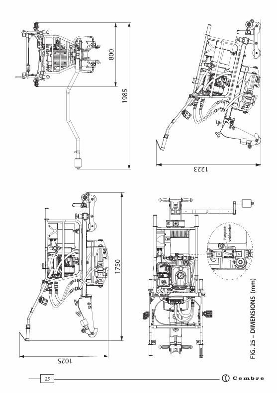
Dimensions see Fig. 25 page 25
Resistance between rail and wheel MΩ ≥ 1
Weight
Complete machine kg 128
Pump unit kg 59
Clamp unit kg 54
Carriage kg 9
3rd wheel bar kg 5
Combustion engine
Type 4-stroke, overhead valve, single cylinder
Model Honda GX200 UT2-SMCR OH
Displacement cm³ 196 cm³
Power kW (HP) 4.1 (5.6)
Revs. rpm 3600
Exhaust emissions the engine is certifi ed Euro 2 and meets U.S. EPA EXH/EVP
and CALIFORNIA SORE EXH/EVP REGS FOR 2013
Fuel unleaded regular grade petrol
Tank capacity lt 3,1
Recommended oil SAE 10W-30 (0,6 litri)
Start by rope pull with automatic rewind
Hydraulic pump
Max. pressure MPa 25
Oil supply 35 litres/minute
Oil capacity kg 4,5
Speed rpm 3500
Recommended oil kg (lbs) PANOLIN HLP SYNTH E68
Acoustic noise (1) dB LpA
86,4 (A) LpCPeak
<130 (C) LWA
101,0 (A)
Vibration (2) m/s2 4,63 max.
1. GENERAL CHARACTERISTICS(*
) "P
an
dro
l" is
a P
an
dro
l Ltd
tra
dem
ark
.
(1) Directive 2006/42/EC, annexe 1, point 1.7.4.2 letter u
LpA
= weighted continuous acoustic pressure level equivalent.
LpCPeak
= maximum value of the weighted acoustic displacement pressure at the work place.
LWA
= acoustic power level emitted by the machine.
(2) Directive 2006/42/EC, annexe 1, point 2.2.1.1
Weighted root mean square in frequency of the acceleration the upper limbs are exposed to for each biodynamic reference axis. Tests carried out in compliance with the indications contained in EN ISO 5349-1/2 Standard, and under operating conditions much more severe than those normally found.

5
2. UNPACKING THE MACHINE
To reduce overall dimensions and weight during transport, the machine is supplied disassembled in sturdy
wooden crates.
The four component units are easily reassembled (Ref. to Fig. 1):
– Pump unit: combustion engine/hydraulic pump for clamp operation.
– Clamp unit: for inserting and extracting clips.
– Carriage: for supporting and moving the machine along the track.
– 3rd wheel bar: for stability and vertical positioning (the third wheel (46) is supplied
disconnected from the bar (48)).
2.1) Transporting the machine
The four units are well balanced for easy transportation in accordance with the table and diagrams in Fig. 1. For
uniform weight distribution when carrying the pump and clamp units, always use the transportation handles
provided.
Ensure appropriate Personal Protective Equipment is used to avoid injury during transportation.
AC
B
A 18 kg
B 18 kg
C 18 kg
D 9 kg
E 5 kg
F 19 kg
G 19 kg
H 21 kg
D F
CR-PCMD PU-PCMDSC-PCMD
EG
H
FIG. 1
CUEC-PCMD

6
3. DESCRIPTION OF THE MACHINE
01 TRANSPORTATION HANDLES
02 OIL COOLING FINS
03 HYDRAULIC PUMP
04 WORKLIGHT ON/OFF SWITCH
06 QUICK RELEASE FEMALE AUTOMATIC HYDRAULIC COUPLER
07 HANDLEBAR LOCKING WINGNUT
08 QUICK RELEASE MALE AUTOMATIC HYDRAULIC COUPLER
09 BRAKE RELEASE CONNECTOR HOLDER (WHEN NOT IN USE)
10 WORKLIGHT
11 HANDLEBAR
12 BRAKE RELEASE LEVER
13 CLAMP DRIVE BUTTON FOR INSERTION/EXTRACTION
14 UPLIFT SETTING BUTTON not enabled for e-clip clamp unit CUEC-PCMD
15 CLAMP CONTROL SWITCH
16 CLAMP RETURN BUTTON
17 STOP/EMERGENCY BUTTON
18 ENGINE
19 WORKLIGHT
20 PUMP UNIT FASTENING/RELEASE KNOB
21 ELECTRICAL TERMINAL BOX
22 DISPLAY
23 FRAME
24 TRANSPORT HANDLE
25 CLAMP UNIT LOCATING PINS
26 PUMP UNIT LOCATING PINS
27 HYDRAULIC FLEXIBLE HOSES
28 KNOB ADJUSTMENT HEIGHT SUSPENSION
29 KNOB ADJUSTMENT INTENSITY SUSPENSION
30 TRANSPORTATION HANDLES
31 REAR ARM WHEEL
32 HYDRAULIC FLEXIBLE HOSES
33 INSERTION/EXTRACTION TOOTH
34 LOCATOR PLATE
35 HYDRAULIC PISTON
36 BRAKE RELEASE CONNECTOR SOCKET
37 GAS SPRING
38 REAR ARM WHEEL LOCK/RELEASE KNOB
39 TRANSPORTATION HANDLES
40 3rd WHEEL ARM FASTENING/RELEASE KNOB
41 FRONT HEIGHT ADJUSTMENT KNOB
42 CLAMP UNIT FASTENING/RELEASE KNOB
43 CARRIAGE WHEELS
44 SUPPORT WHEEL
45 SUPPORT WHEEL ADJUSTMENT LEVER
46 ARM

7
0103 04 06
08
10
13
1819
22
23
14
15
FIG. 2
12
26
25
27
38
30
31
34
46
3rd WHEEL BAR
CLAMP UNIT
CARRIAGE
43
39
42
40
36
PUMP UNIT
02
20 16
37
44
45
09
29
41
17
11
24
07
21
28
33
35
32
8
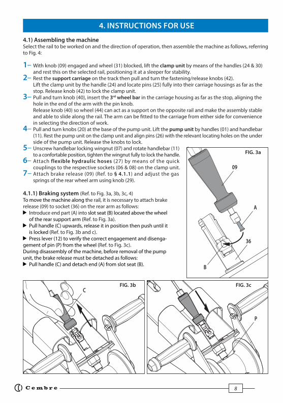
4.1) Assembling the machine Select the rail to be worked on and the direction of operation, then assemble the machine as follows, referring to Fig. 4:
1– With knob (09) engaged and wheel (31) blocked, lift the clamp unit by means of the handles (24 & 30) and rest this on the selected rail, positioning it at a sleeper for stability. 2– Rest the support carriage on the track then pull and turn the fastening/release knobs (42). Lift the clamp unit by the handle (24) and locate pins (25) fully into their carriage housings as far as the stop. Release knob (42) to lock the clamp unit. 3– Pull and turn knob (40), insert the 3rd wheel bar in the carriage housing as far as the stop, aligning the hole in the end of the arm with the pin knob. Release knob (40) so wheel (44) can act as a support on the opposite rail and make the assembly stable and able to slide along the rail. The arm can be fi tted to the carriage from either side for convenience in selecting the direction of work. 4– Pull and turn knobs (20) at the base of the pump unit. Lift the pump unit by handles (01) and handlebar (11). Rest the pump unit on the clamp unit and align pins (26) with the relevant locating holes on the under side of the pump unit. Release the knobs to lock.5– Unscrew handlebar locking wingnut (07) and rotate handlebar (11) to a confortable position, tighten the wingnut fully to lock the handle.6– Attach flexible hydraulic hoses (27) by means of the quick couplings to the respective sockets (06 & 08) on the clamp unit. 7– Attach brake release (09) (Ref. to § 4.1.1) and adjust the gas springs of the rear wheel arm using knob (29).
4.1.1) Braking system (Ref. to Fig. 3a, 3b, 3c, 4)To move the machine along the rail, it is necessary to attach brake release (09) to socket (36) on the rear arm as follows:
Introduce end part (A) into slot seat (B) located above the wheel of the rear support arm (Ref. to Fig. 3a).
Pull handle (C) upwards, release it in position then push until it is locked (Ref. to Fig. 3b and c).
Press lever (12) to verify the correct engagement and disenga-gement of pin (P) from the wheel (Ref. to Fig. 3c).During disassembly of the machine, before removal of the pump unit, the brake release must be detached as follows:
Pull handle (C) and detach end (A) from slot seat (B).
A
B
FIG. 3a
09
FIG. 3b FIG. 3c
4. INSTRUCTIONS FOR USE
36
C
P

9
4
2
7
6
1
3
5
FIG
. 4
01
11
0938 30
31
27
4025
26
44
RA
ILS
SL
EE
PE
R
DIR
ECTI
ON
OF
MO
VEM
ENT
24
39
42
12
06 08
07
41
2928

10
4.2) Disassembling the machine To disassemble the machine:
First lower the rear support arm and lock with
pin (38), block wheel (33) then reverse the process
described in § 4.1.
On the pump unit, disconnect/detach hydraulic
hoses (27) (Ref to Fig. 5a) and brake release (09)
(Ref to Fig. 5b), placing the hoses in their supports
in the clamp unit and the brake release in its
support on the handlebar.
NOTE: Under normal conditions, the time taken to remove the machine from the rail is approximately 60 seconds.
4.3) Moving the machine To move the machine along the rail, the rear
arm must be raised to prevent the clamps
knocking against the e-clips as follows:
1– Pull and turn knob (38). The wheel arm will
be freed (Ref. to Fig. 6).
2– Lift the unit by the handles; the two gas
springs will facilitate full lifting ; the two
springs can be adjusted using knob (29),
turning it clockwise for stiffer springs,
anticlockwise for softer.
3– Press brake release lever (12) against
handlebar (11).
4– Push the machine along the rail.
3
2
4
1
FIG. 6
12
38
FIG. 5a
29
09
27
FIG. 5b
28

11
4.4) Controls When gripping handlebar (11), the operator can easily access all the unit controls and, more specifi cally:
Worklights ON/OFF switch (04): two high effi ciency LED lights allow the clamp area to be eff ectively lit
in poor light conditions and at night.
Brake release lever (12): for safety reasons the machine is equipped with a "dead man's" braking
system on the rear wheel. It is only possible to release the brake by pressing the lever (12), allowing
the machine to move along the rail.
Clamp operation button (13): enables operation of the clamps according to the mode selected with
switch (15).
Settings button (14): not enabled for e-clip clamp unit CUEC-PCMD.
Clamp control selector (15): allows the selection of insertion "IN" or extraction "OUT" of the clamps.
Clamp return button (16): enables the clamps to be brought back to their starting position.
Stop/emergency button (17) in a very visible position and easy to operate to stop the machine normally
and in case of an emergency.
NOTE: when this button is pressed it remains in OFF position. To start the engine, the button should be turned
clockwise so that it lifts automatically into the ON position.
The engine will not start unless the red button (17) is lifted.
FIG. 7
1613
12
0417 15 1411
12
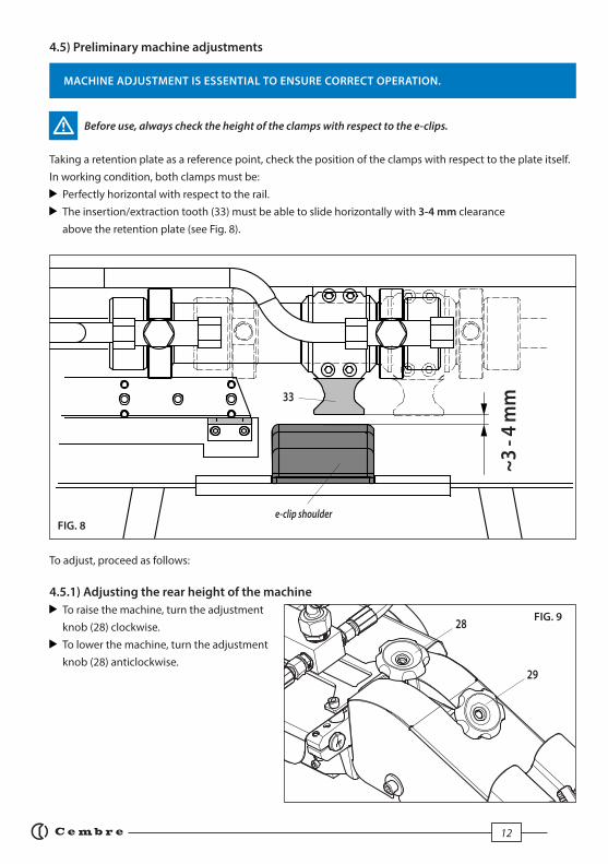
4.5) Preliminary machine adjustments
MACHINE ADJUSTMENT IS ESSENTIAL TO ENSURE CORRECT OPERATION.
Before use, always check the height of the clamps with respect to the e-clips.
Taking a retention plate as a reference point, check the position of the clamps with respect to the plate itself.
In working condition, both clamps must be:
Perfectly horizontal with respect to the rail.
The insertion/extraction tooth (33) must be able to slide horizontally with 3-4 mm clearance
above the retention plate (see Fig. 8).
To adjust, proceed as follows:
4.5.1) Adjusting the rear height of the machine
To raise the machine, turn the adjustment
knob (28) clockwise.
To lower the machine, turn the adjustment
knob (28) anticlockwise.
33
~3
- 4
mm
FIG. 8
FIG. 928
29
e-clip shoulder
13
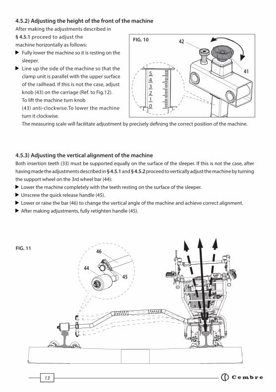
4.5.2) Adjusting the height of the front of the machine
After making the adjustments described in
§ 4.5.1 proceed to adjust the
machine horizontally as follows:
Fully lower the machine so it is resting on the
sleeper.
Line up the side of the machine so that the
clamp unit is parallel with the upper surface
of the railhead. If this is not the case, adjust
knob (43) on the carriage (Ref. to Fig.12).
To lift the machine turn knob
(43) anti-clockwise.To lower the machine
turn it clockwise.
The measuring scale will facilitate adjustment by precisely defi ning the correct position of the machine.
4.5.3) Adjusting the vertical alignment of the machine
Both insertion teeth (33) must be supported equally on the surface of the sleeper. If this is not the case, after
having made the adjustments described in § 4.5.1 and § 4.5.2 proceed to vertically adjust the machine by turning
the support wheel on the 3rd wheel bar (44):
Lower the machine completely with the teeth resting on the surface of the sleeper.
Unscrew the quick release handle (45).
Lower or raise the bar (46) to change the vertical angle of the machine and achieve correct alignment.
After making adjustments, fully retighten handle (45).
FIG. 10
012345
42
41
44
46
45
FIG. 11

14
4.6) Operation
Before use, always check:
Integrity of the machine.
The correct coupling of the units making up the machine.
Correct connection of the quick couplings and braking system.
Correct level of oil in pump.
For any oil leaks in the hydraulic circuit (hoses, pump).
Flexible hoses are in good condition and show no signs of wear or crushing.
Protection devices in the clamp areas are fi rm and show no signs of damage.
That the engine fuel tank cap is tight. Petrol is highly infl ammable and can explode.
Start the engine (see § 6).
4.6.1) Inserting clips
Make sure the locking knob (38) of the rear wheel is released (see § 4.3).
Push the machine to the clips on which operations are to be performed (see § 4.3).
Position the e-clips in the retention plate eyelets, on both sides of the rail.
Make sure the teeth (33) of the clamps are moved fully back.
Completely lower the machine, positioning the locator plates (34) near the e-clip shoulder (see Fig. 13a).
e-clips
34
33
e-clip shoulder
FIG. 12
FIG. 13a

15
Turn the clamp control selector (15) to the insertion position “IN”.
Push the button for insertion (13) to gradually move the teeth forwards with consequent insertion of
both e-clips (see Fig. 13b and 13c).
When performing the insertion operation, each clamp teeth (33) will move in opposite directions.
Movement of one of the clamps is schematically shown in the illustrations;
the other will have an identical and opposite movement.
Once the insertion has been completed, the clamps are retracted automatically while still holding down
the clamp operation button (13)(Ref. to Fig. 13d).
Lift the machine, move to the next clips.
Repeat the above operations.
33
33
33
FIG. 13b
FIG. 13c
FIG. 13d

16
4.6.2) Extracting clips
Push the machine to the clips on which operations are to be performed (see § 4.3).
Make sure the teeth (33) of the clamps are moved fully.
Completely lower the machine, positioning the yellow locator plates (34) near the e-clip shoulder
(see Fig. 14a).
Turn the clamp control selector (15) to the extraction position “OUT”.
Push the button for extraction (13) to gradually move the teeth forwards with consequent extraction
of both e-clips (see Fig. 14b and 14c).
When performing the extraction operation, each clamps teeth (33) will move in opposite directions.
Movement of one of the clamps is schematically shown in the illustrations;
the other will have an identical and opposite movement.
Once the extraction is complete, lift the machine and move on to the next clips.
Repeat the above extraction operations.
33
33
33
34
e-clip
shoulder
33
FIG. 14a
FIG. 14b
FIG. 14c FIG. 14d

17
5. DISPLAY
The OLED display (22) is located on the outer face of the electrical terminal box (21) and is activated when the
machine is switched on and automatically deactivated around 30 secs after turning the machine off .
The display shows:
The main operational parameters of the machine processed by the circuit board, such as number of full
cycles and hours of work.
Indications of the condition of the machine e.g maintenance requirements.
Any operational or procedural ERRORS.
Use the touch button to navigate through the menu screens to manage
INFORMATION.
5.1) INFORMATION SCREENS: display a pre-determined parameter which will then appear each time the
tool is started and during the entire work cycle.
Cembre logo
n° full cycles
n° working hours
(standard factory set screen)
n° of hours since last maintenance
n° of hours until next maintenance
Cembre logo, machine model
Machine serial n°
1000000 h 9999.9
PCM3P
h 9999.9 h 9999.9
The capacitive menu selection button may not work if touched using objects or when wearing
gloves, therefore always operate it using a bare fi nger.
One cycle corresponds to one sleeper.
5.2) WARNINGS: these appear during operation and notify the operator of the status of the machine:
NO. OF CYCLES TO MAINTENANCE REACHED: the machine continues to work however,
it is recommended that it is sent to Cembre for a complete overhaul (see § 8).
NOTE: this message remains on the display.
h 9999.9

18
Message Error description Solution
Accelerator motor reset error. Replace the faulty component, contact Cembre.
Accelerator motor minimum
positioning error.
Replace the faulty component, contact
Cembre.
Accelerator motor maximum
positioning error.
Replace the faulty component, contact
Cembre.
Generator power supply frequency
out of range.
Increase the engine idling speed or replace the generator, contact Cembre.
Motor or pcb driver faulty. Replace the motor or electronics board,
contact Cembre.
Parameter storage failure in eeprom. Retry, if it does not work the memory is
damaged, contact Cembre.
Failure to store work data in eeprom. Electronics board faulty and needs
replacing, contact Cembre.
Pressure sensor disconnected or
faulty at start up.
Check the connection.
If the error persists replace the sensor,
contact Cembre.
Pressure off set error at start up. Replace the pressure sensor, contact
Cembre.
Error can be reset by pressing buttons 13 and 16 simultaneously for 5 seconds;
if the error persists contact Cembre.
Error messages remain on the display until they are reset.
001
002
003
004
005
006
007
009
010
5.3) ERRORS: these appear during operation and notify the operator of procedural or operational errors.

19
6. STARTING THE ENGINE
If the machine has been running the
Exhaust may be very hot, beware when
using the Starting Cable.
The machine is equipped with an automatic
accelerator which serves to accelerate the
combustion engine to bring it to different
engine speeds according to the different work
phases. When the engine is started it will adjust
automatically, by setting the intermediate
and maximum speed then to find and set
its minimum speed. The procedure for
starting the engine is:
After start-up wait for the engine to
regulate the three engine speeds.
Put red stop button (17) (see § 4.3) in
the "ON" position (Ref. to Fig.15a) by turning
it clockwise.
The engine will not start unless the
red button (17) is lifted.
Move the fuel stopcock to "ON" position (Ref. to Fig. 15b).
Move the air lever to "CLOSE" position
(Ref. to Fig. 15b).
Do not use the air lever if the engine is hot
and the air temperature is high enough.
Start the engine by pulling the starting cable
until resistance is felt then pull
with force (Ref. to Fig. 15c).
IMPORTANT: Do not allow the cable knob to
return forcefully and knock against the frame.
Return this slowly to its original position.
To prevent damage to the starting device.
As the engine heats up, gradually move the
air lever to "OPEN" position (Ref. to Fig. 15b).
To stop the engine in emergency condition,
press red button (17).
To stop the engine in normal conditions:
Press the button (17).
Move the fuel stopcock to "OFF".
FIG. 15a
FIG. 15b
FIG. 15c
17
Air lever CLOSE
OPEN
Fuel stopcock OFF ON
Starting cable knob

20
TROUBLESHOOTING
When the starting cable is pulled, the engine fails to start:
Is the Stop/Emergency button (17) released? (see § 4.4).
Is there enough oil in the engine?
– The engine has an oil alert system to prevent damage caused by too little oil. Before the level drops
below safe limits, the alarm system automatically stops the engine.
Refer to the "HONDA owner’s manual" for the recommended oil type and topping up procedure.
THE HYDRAULIC OIL SUPPLIED WITH THE MACHINE IS INTENDED ONLY FOR USE IN THE HYDRAULIC PUMP AND
MUST NOT BE USED IN THE ENGINE.
Is the fuel stopcock open?
Is there fuel in the tank?
Is fuel reaching the carburettor?
– To check, loosen the carburettor drainage screw with fuel stopcock open and refer to the "HONDA owner’s manual".
Is the spark plug producing a spark?
– Remove the plug cap, clean around the plug and remove it using the spanner provided.
– Fit the plug back in the cap.
– Move button (17) to "ON".
– Earth the side electrode then pull the starting cable and check to see if the plug produces a spark.
If the engine still fails to start, contact Cembre (see § 8).
Before servicing or removing any parts of the machine, stop the engine and allow it to cool. Always
remove the spark plug cap from the spark plug when servicing the engine to prevent accidental
starting.
7.1) Routine maintenance of the machineAt the end of each day, wipe the machine carefully using a clean cloth, being careful to eliminate all dirt, espe-
cially near the moving parts such as the clamp teeth, piston rods and wheels. Do not rest the machine or units
directly on dusty or muddy ground.
Regularly perform the following operations or inspections:
Tighten all bolts.
Check the integrity of the rubber dampers under the engine and pump, and on top of the clamp unit
which reduce vibration caused by those components.
Replace the insertion teeth (33) and locator plates (34) as these become worn or damaged by long or
improper use.
7.1.1) Maintenance of braking systemThe braking system is of robust construction and will require very little maintenance, however the following
routine checks should be performed.
Dust, sand and dirt are a danger for any mechanical device. Avoid putting the machine on muddy ground.
After every use, the machine must be wiped with a clean cloth, taking care to remove any residue, especially
around moving parts.
7. MAINTENANCE
All electrical and mechanical maintenance shall only be carried out by authorised persons in accordance
with a safe system of work and Cembre instructions.

21
Before every use:
Check rear wheel for resistance, it should not be free rotating.
Ensure wheel is clean, removing any dirt or mud.
Check for signs of damage.
Every 6 months:
Check for excessive braking on wheel. It should roll along rail when pushed but will slide if excessive
braking occurs.
7.1.2) Maintenance of clamp unit
Before every use:
Check cable, linkages, springs and rear wheel for signs of damage.
Check linkages are free moving.
Ensure brake cable moves without resistance and is not damaged.
With brake released, check the wheel rotates freely.
Check that, when handlebar lever (12) is in the raised position, the brake is engaged.
Ensure the wheel is clean of dirt and mud.
Check that, before assembly, the wheel does not rotate one full turn in either direction.
Ensure brake coupling above rear wheel is free
of dirt and mud.
Every 6 months
Check wheel pockets for excessive wear.
If braking eff ectiveness is compromised, replace
wheel.
Check for wear on pivots.
Ensure fasteners are secure.
Check for wear on brake coupling. Parts should
mate securely.
Clean all moving parts and lubricate as required.
12
FIG. 16
FIG. 17
22
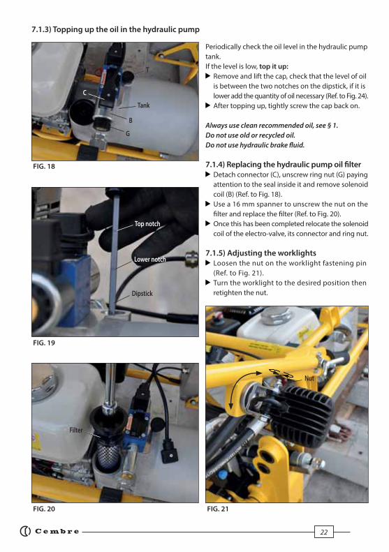
7.1.3) Topping up the oil in the hydraulic pump Periodically check the oil level in the hydraulic pump
tank.
If the level is low, top it up:
Remove and lift the cap, check that the level of oil
is between the two notches on the dipstick, if it is
lower add the quantity of oil necessary (Ref. to Fig. 24).
After topping up, tightly screw the cap back on.
Always use clean recommended oil, see § 1.
Do not use old or recycled oil.
Do not use hydraulic brake fl uid.
7.1.4) Replacing the hydraulic pump oil fi lter Detach connector (C), unscrew ring nut (G) paying
attention to the seal inside it and remove solenoid
coil (B) (Ref. to Fig. 18).
Use a 16 mm spanner to unscrew the nut on the
fi lter and replace the fi lter (Ref. to Fig. 20).
Once this has been completed relocate the solenoid
coil of the electro-valve, its connector and ring nut.
7.1.5) Adjusting the worklights Loosen the nut on the worklight fastening pin
(Ref. to Fig. 21).
Turn the worklight to the desired position then
retighten the nut.
FIG. 18
FIG. 19
FIG. 20 FIG. 21
Tank
T
Top notch
Lower notch
Dipstick
G
B
C
Filter
Nut

23
7.2) Routine maintenance of the engine
Checks and periodic servicing are indispensable to ensure smooth engine operation.
Refer to the "HONDA owner’s manual" supplied with the machine for the following operations:
Oil change (fi rst change after 20 hours of work)
Air fi lter assistance (see double-element type)
Cleaning sediment from sump
Spark plug cleaning; recommended plugs BPR6ES (NGK) or W20EPR-U (DENSE)
Minimum carburettor setting
7.3) Long periods of inactivity
Store the machine in a dry environment and adequately protect it against accidental damage and contamination.
For information on the engine, refer to the "HONDA owner’s manual".
7.1.6) Changing the gas springs Replace the gas springs when required as follows:
On both sites loosen screws (A) with an 8 mm
Allen key and screws (B) with a 6 mm Allen key then
remove the casing (Ref. to Fig. 22).
Unlock the arm in order to extend the springs
(Ref to Fig. 23).
Use a fi nger to release the retaining rings located
at the ends of the spring and simultaneously
detach it from the pins (Ref. to Fig. 24).
Place the new spring on the same pins, pressing
it with force until it is inserted, respecting its
original orientation.
Reposition the retaining rings.
Repeat this process for both springs.
Replace the casing and fasten it by tightening the
screws. FIG. 22
FIG. 24FIG. 23
A
B
Casing
Gas spring
Retaining ring

24
Gen
eral
cle
anin
g w
ith
a c
lean
cl
oth
, pay
ing
att
enti
on
to
re
mo
ve s
ettl
ed d
irt
Sto
re th
e m
ach
ine
in a
dry
pla
ce,
pro
tect
ing
it fr
om
sh
ock
s an
d d
ust
Vis
ual
& m
anu
al c
hec
ks
(tig
hte
n if
nec
essa
ry)
Co
mp
lete
tig
hte
nin
g
Vis
ual
ch
eck
of i
nte
gri
ty
Rep
lace
men
t
Vis
ual
& m
anu
al c
hec
ks(t
igh
ten
if n
eces
sary
)
Co
mp
lete
tig
hte
nin
g
Visu
al &
man
ual c
heck
s of
inte
grity
Rep
lace
men
t
Visu
al &
man
ual c
heck
s of
inte
grity
Rep
lace
men
t
Ch
eck
rese
rvo
ir l
evel
(To
p u
p if
nec
essa
ry)
Rep
lace
men
t
Rep
lace
men
t
Rep
lace
men
t
Rep
lace
men
t
PE
RIO
DIC
OV
ER
HA
UL
Pe
rfo
rmed
at t
he
pre
scri
bed
inte
rval
s o
r at t
he
nu
mb
er o
f in
dic
ated
wor
kin
g h
ours
or a
t th
e oc
curr
ence
of i
nd
icat
ed e
xtra
ord
inar
y ev
ents
At
ev
ery
use
3
00
ho
urs
Pre
sen
ce
of
ev
ide
nt
sig
ns
of
we
ar
ITE
M
A
CT
ION
Co
mp
lete
mac
hin
e
Bo
lts
and
nu
ts
Flex
ible
ho
se
Hyd
rau
lic c
ou
ple
rs
Cla
mp
un
it r
ub
ber
dam
per
s o
f th
e u
nit
Inse
rtin
g a
nd
extr
acti
on
tee
th (3
3)
Hyd
rau
lic o
il
Hyd
rau
lic o
il fi
lter
10
0 h
ou
rs
Gas
sp
rin
gs
Acc
eler
ato
r ca
ble
Lo
ng
pe
rio
ds
of
ina
ctiv
ity
25
FIG
. 25
– D
IME
NS
ION
S (
mm
)
XXXXXX
Pum
p un
it
seria
l num
ber
1223
19
85
80
01
75
0
1025

26
In the case of a breakdown contact our Area Agent who will advise you on the problem and give you the neces-
sary instructions on how to dispatch the machine to our nearest service Centre. If possible, attach a copy of the
Test Certifi cate supplied by Cembre to the machine or fi ll in and attach the form available in the “ASSISTANCE”
section of the Cembre website.
8. RETURN TO Cembre FOR OVERHAUL
---------------------------------------------------------------------------------------------------
---------------------------------------------------------------------------------------------------
---------------------------------------------------------------------------------------------------
---------------------------------------------------------------------------------------------------
---------------------------------------------------------------------------------------------------
---------------------------------------------------------------------------------------------------
---------------------------------------------------------------------------------------------------
---------------------------------------------------------------------------------------------------
---------------------------------------------------------------------------------------------------
---------------------------------------------------------------------------------------------------
---------------------------------------------------------------------------------------------------
---------------------------------------------------------------------------------------------------
---------------------------------------------------------------------------------------------------
---------------------------------------------------------------------------------------------------
NOTE

27

2828
This
ma
nu
al i
s th
e p
rop
erty
of C
embr
e: a
ny
rep
rod
uct
ion
is fo
rbid
den
wit
ho
ut
wri
tten
per
mis
sio
n.
cembre.com
Cembre Ltd.Dunton ParkKingsbury Road, Curdworth - Sutton ColdfieldWest Midlands B76 9EB (UK)Ph. +44 01675 470440 - Fax +44 01675 [email protected]
Cembre S.a.r.l.22 Avenue Ferdinand de Lesseps91420 Morangis (France) Tél. +33 01 60 49 11 90 - Fax +33 01 60 49 29 10CS 92014 - 91423 Morangis Cé[email protected]
Cembre España S.L.U.Calle Verano 6 y 8 - P.I. Las Monjas 28850 Torrejón de Ardoz - Madrid (España)Tel. +34 91 4852580 Fax +34 91 [email protected]
Cembre GmbH Heidemannstraße 16680939 München (Deutschland)Tel. +49 89 [email protected]
Cembre Inc. Raritan Center Business Park300 Columbus Circle - Suite FEdison, New Jersey 08837 (USA)Ph. +1 732 225-7415 - Fax +1 732 [email protected]
Cembre S.p.A. Via Serenissima, 925135 Brescia (Italia)Tel. +39 030 36921Fax +39 030 [email protected]
Cembre GmbH (Betriebsstätte Weinstadt)Boschstraße 771384 Weinstadt (Deutschland)Tel. +49 7151 20536 - [email protected]
cod. 6261425


