Download - LUNAR REGOLITH EXCAVATOR - Auburn University
LUNAR REGOLITH EXCAVATORNASA : Corporation 2
Summer 2009
Instructor : Dr. Beale
Sponsor: Rob Mueller, NASA Lunar Surface Systems Lead Engineer
Evaluator : Dr. Madsen, Dr. Jackson, Dr. Marghitu
Project Manager: Allan Westenhofer
Presenting: Harrison Davis, Dale Braxton
August 4, 2009

Outline
1. Introduction to Design Objective
2. Subsystems Concepts and Analysis
3. Resource BudgetingResource Budgeting
4. Project Management
5. Conclusion and Future Goals
1.1 Mission Objective
� The mission objective is to create an un-manned lunar device that, while being self-propelled, excavates lunar regolith. The vehicle must be able to be driven and operated remotely. It must efficiently excavate 150 kg of regolith per 30 min efficiently excavate 150 kg of regolith per 30 min in semi-lunar conditions.
1.2 Purpose of Design
� The design is to meet requirements for lunar conditions. The regolith excavated will be used by NASA in a process to extract oxygen and create water for a lunar colony. Certain requirements are set for power, size, and mass to ensure a feasible design. These requirements have been set by Rob feasible design. These requirements have been set by Rob Mueller, NASA Lunar Surface Systems Lead Engineer and the committee of the CSEWI competition.
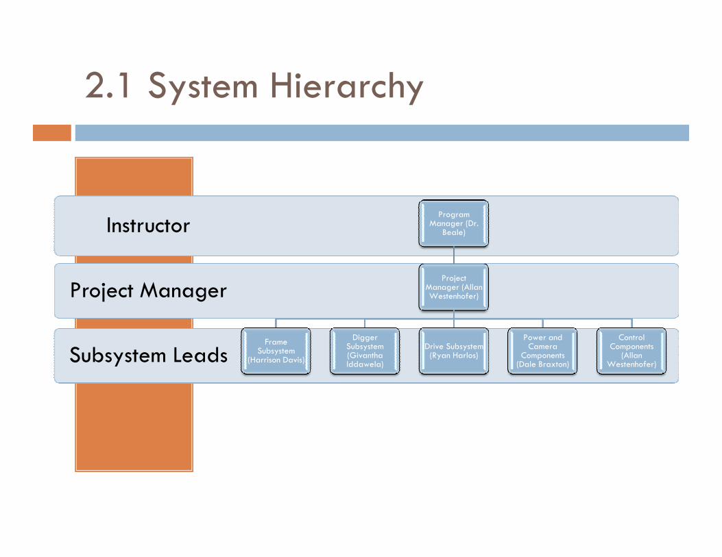
2.1 System Hierarchy
Project Manager
InstructorProgram
Manager (Dr. Beale)
Project
Subsystem Leads
Project ManagerProject
Manager (Allan Westenhofer)
Frame Subsystem
(Harrison Davis)
Digger Subsystem (Givantha Iddawela)
Drive Subsystem (Ryan Harlos)
Power and Camera
Components (Dale Braxton)
Control Components
(Allan Westenhofer)
2.2.1 Digger Subsystem
� Design Objectives
� Ability to raise the bucket above an elevation of 0.5 meters
� The system length should be no longer than 1m
� High bucket capacity
� Light weight design
� Minimal power usage
� Simplicity
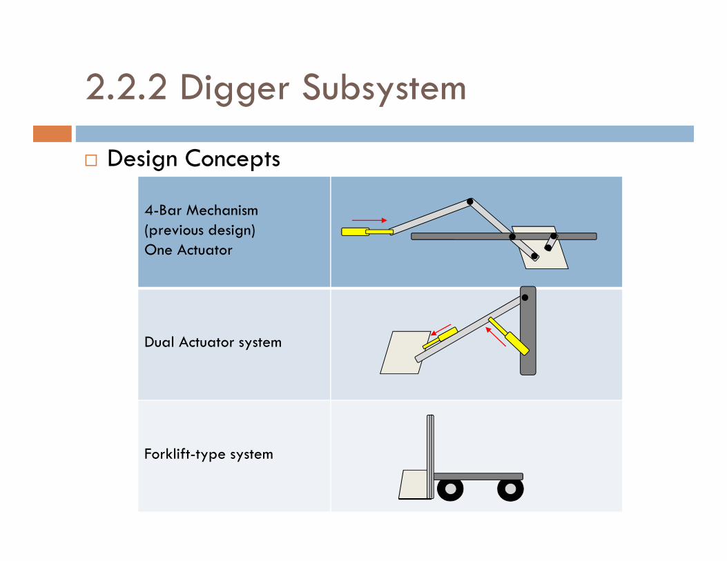
� Design Concepts
4-Bar Mechanism(previous design)One Actuator
2.2.2 Digger Subsystem
Dual Actuator system
Forklift-type system
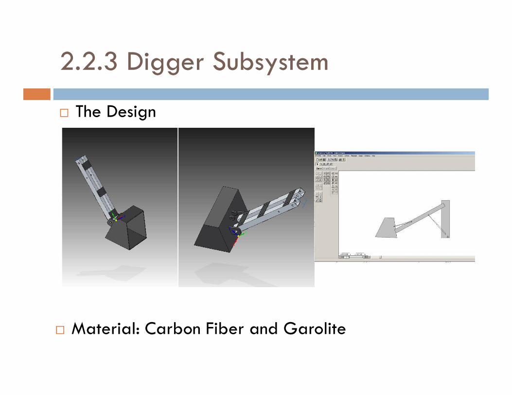
� The Design
2.2.3 Digger Subsystem
� Material: Carbon Fiber and Garolite
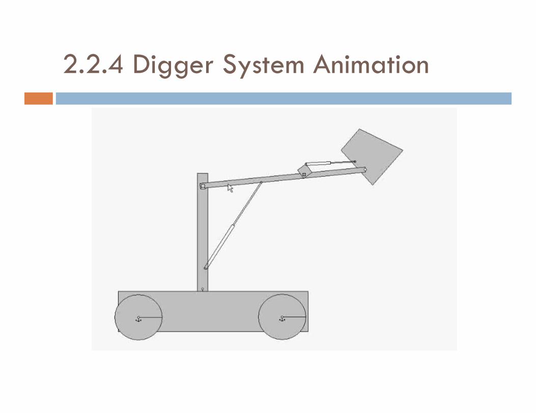
2.2.4 Digger System Animation
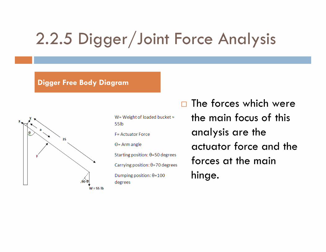
2.2.5 Digger/Joint Force Analysis
� The forces which were the main focus of this analysis are the
Digger Free Body Diagram
analysis are the actuator force and the forces at the main hinge.

2.2.6 Joint Force Analysis (cont.)
MatLabAnalysis:
x vs theta (for a=7in)
As the angle of the arm increases, the force in the x direction decreases
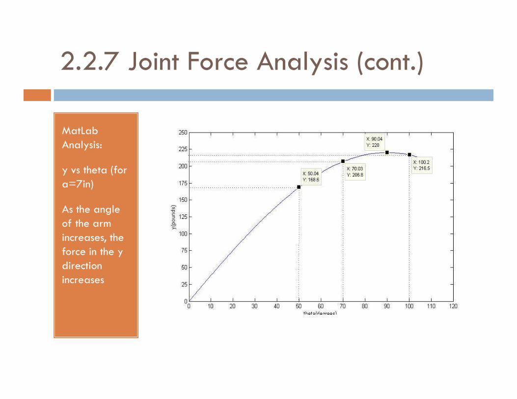
2.2.7 Joint Force Analysis (cont.)
MatLabAnalysis:
y vs theta (for a=7in)
As the angle of the arm increases, the force in the y direction increases

2.2.8 Joint Force Analysis (cont.)
actuator force (F) vs a
As the distance of the arm the arm actuator increases, the amount of force to raise the arm decreases
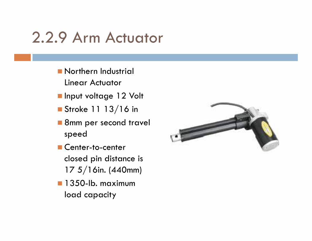
2.2.9 Arm Actuator
� Northern Industrial Linear Actuator
� Input voltage 12 Volt
� Stroke 11 13/16 in
� 8mm per second travel � 8mm per second travel speed
� Center-to-center closed pin distance is 17 5/16in. (440mm)
� 1350-lb. maximum load capacity
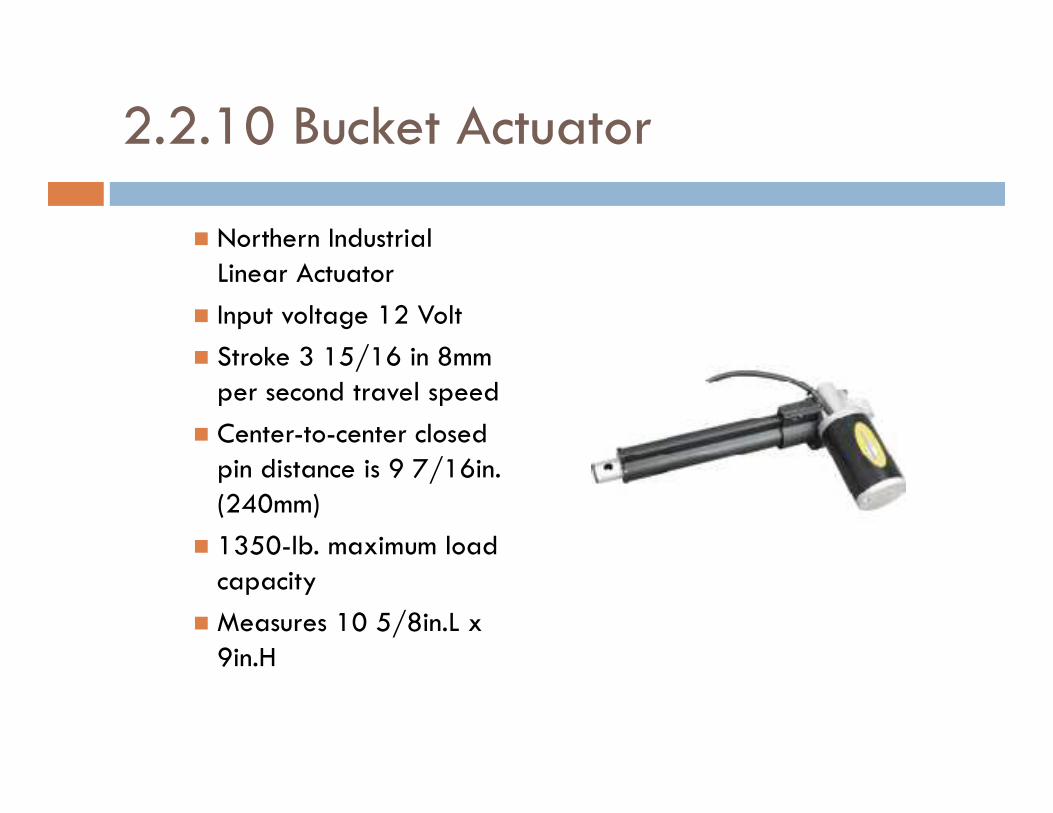
2.2.10 Bucket Actuator
� Northern Industrial Linear Actuator
� Input voltage 12 Volt
� Stroke 3 15/16 in 8mm per second travel speedper second travel speed
� Center-to-center closed pin distance is 9 7/16in. (240mm)
� 1350-lb. maximum load capacity
� Measures 10 5/8in.L x 9in.H
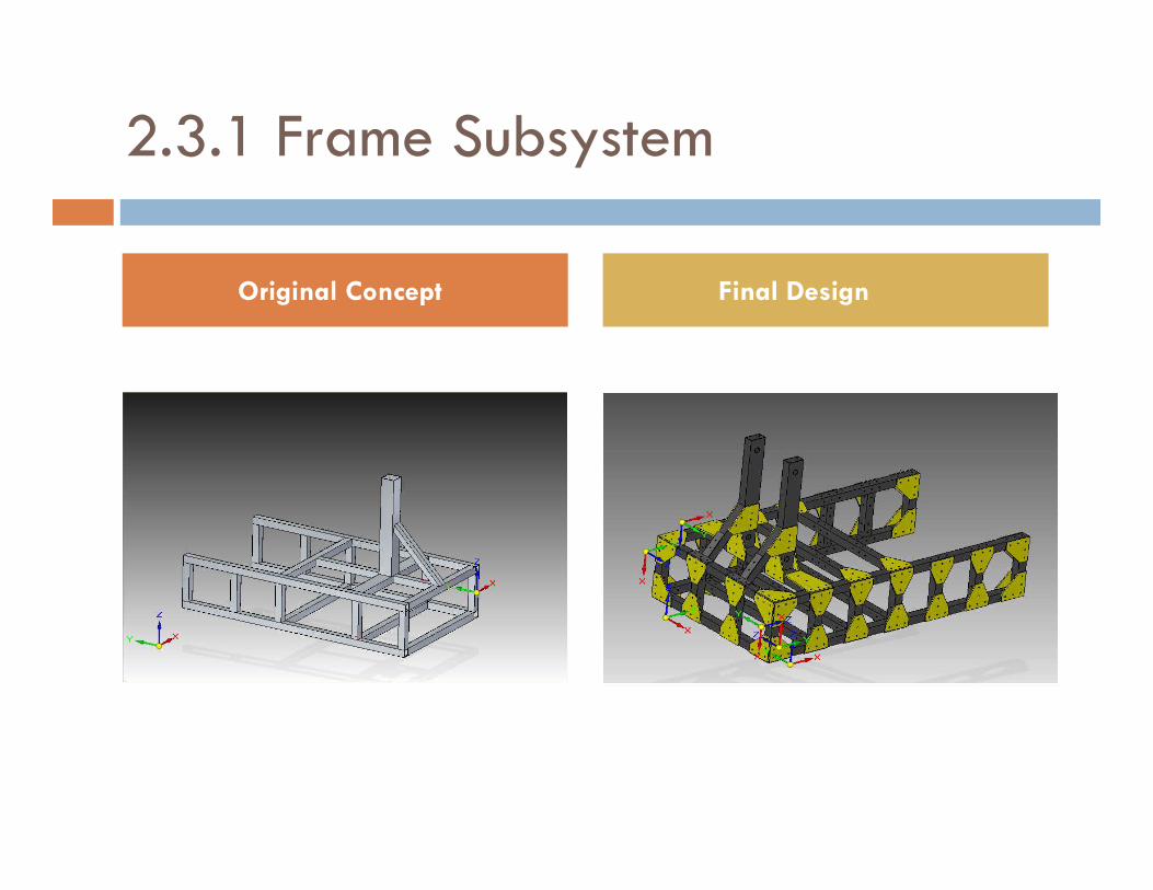
2.3.1 Frame Subsystem
Original Concept Final Design
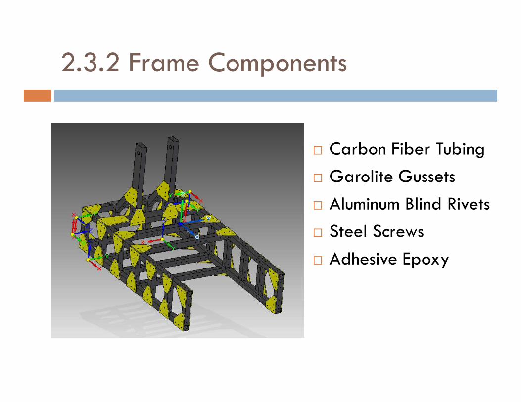
2.3.2 Frame Components
� Carbon Fiber Tubing
� Garolite Gussets
� Aluminum Blind Rivets� Aluminum Blind Rivets
� Steel Screws
� Adhesive Epoxy
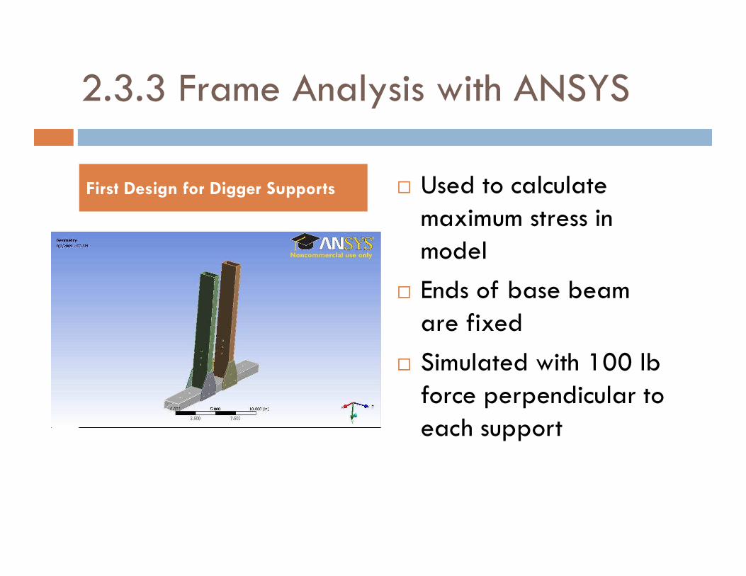
2.3.3 Frame Analysis with ANSYS
� Used to calculate maximum stress in model
� Ends of base beam
First Design for Digger Supports
� Ends of base beam are fixed
� Simulated with 100 lb force perpendicular to each support

2.3.3 Frame Analysis with ANSYS (cont.)
� Wire Meshing created to calculate results from acting loads on model
Wire Mesh Diagram
� Mesh: Patch Conforming Tetrahedrons and Sweeping
� Material properties of carbon fiber used in calculations
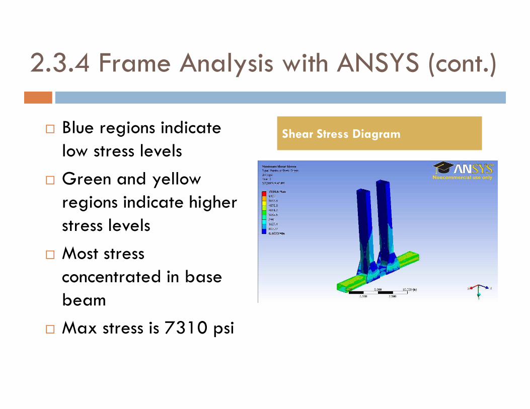
2.3.4 Frame Analysis with ANSYS (cont.)
� Blue regions indicate low stress levels
� Green and yellow regions indicate higher
Shear Stress Diagram
regions indicate higher stress levels
� Most stress concentrated in base beam
� Max stress is 7310 psi
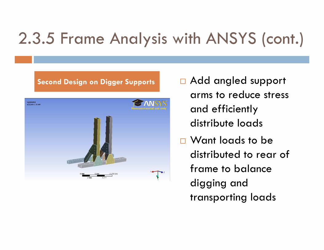
2.3.5 Frame Analysis with ANSYS (cont.)
� Add angled support arms to reduce stress and efficiently distribute loads
Second Design on Digger Supports
distribute loads
� Want loads to be distributed to rear of frame to balance digging and transporting loads
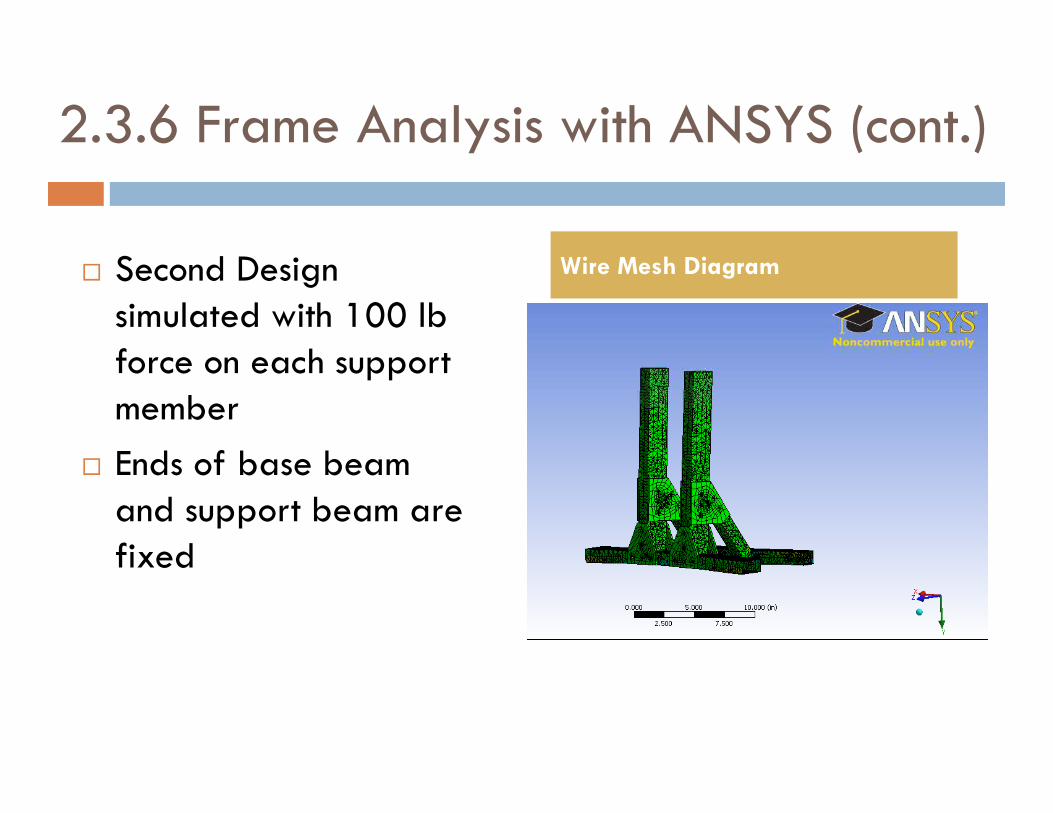
2.3.6 Frame Analysis with ANSYS (cont.)
� Second Design simulated with 100 lb force on each support member
Wire Mesh Diagram
member
� Ends of base beam and support beam are fixed

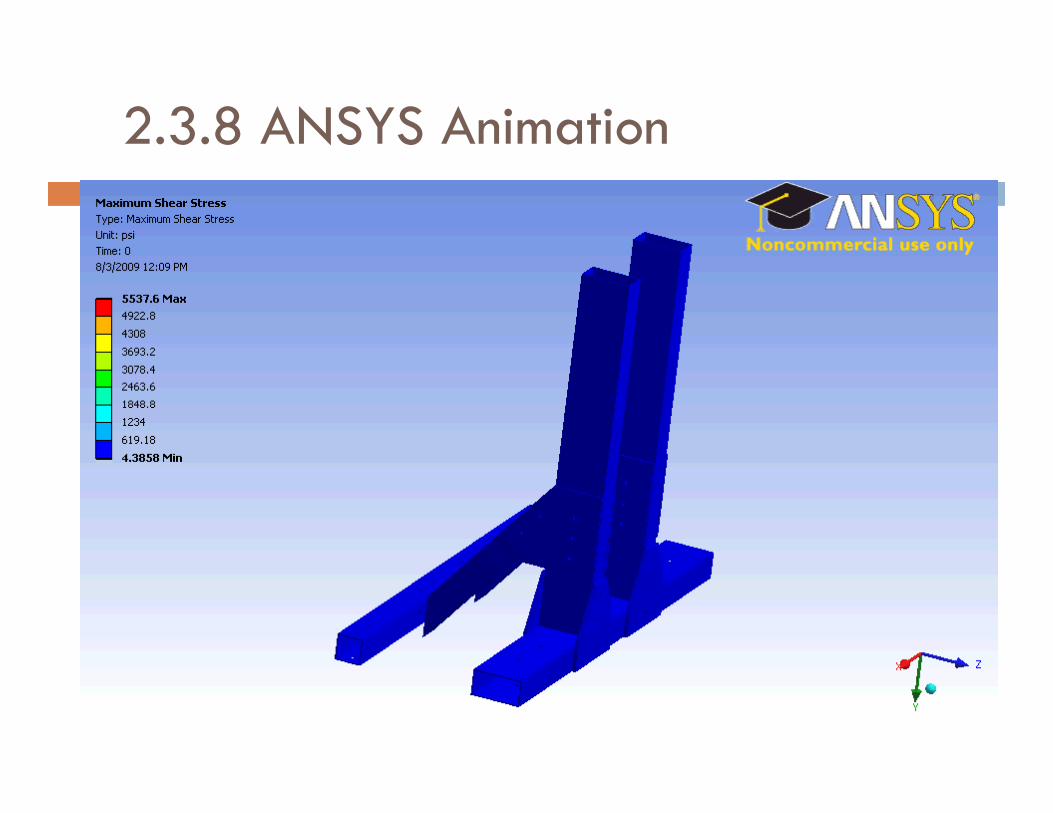
2.3.7 Frame Analysis with ANSYS (cont.)
� Max stress level reduced to 5537 psi
� Stress in base beam reduced
Shear Stress Diagram
reduced
� Load distributed to back support beam and to rear of frame
� Factor of Safety: 115.5
2.3.8 ANSYS Animation
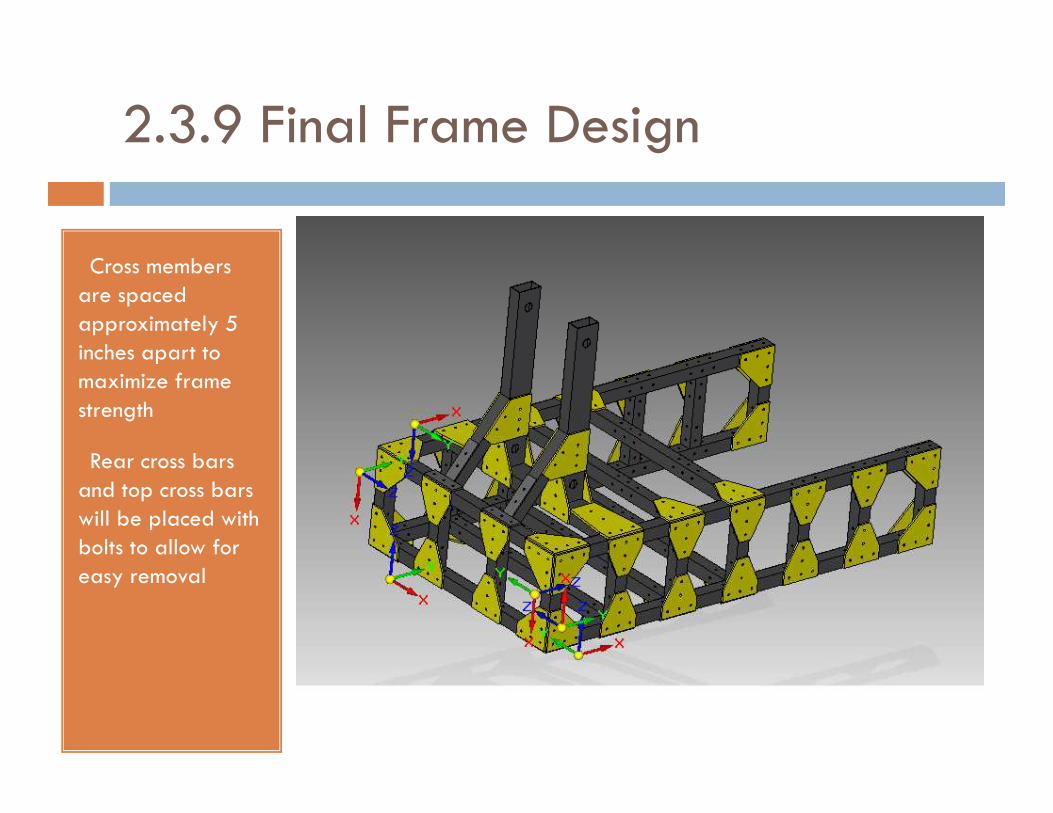
2.3.9 Final Frame Design
• Cross members are spaced approximately 5 inches apart to maximize frame strengthstrength
• Rear cross bars and top cross bars will be placed with bolts to allow for easy removal
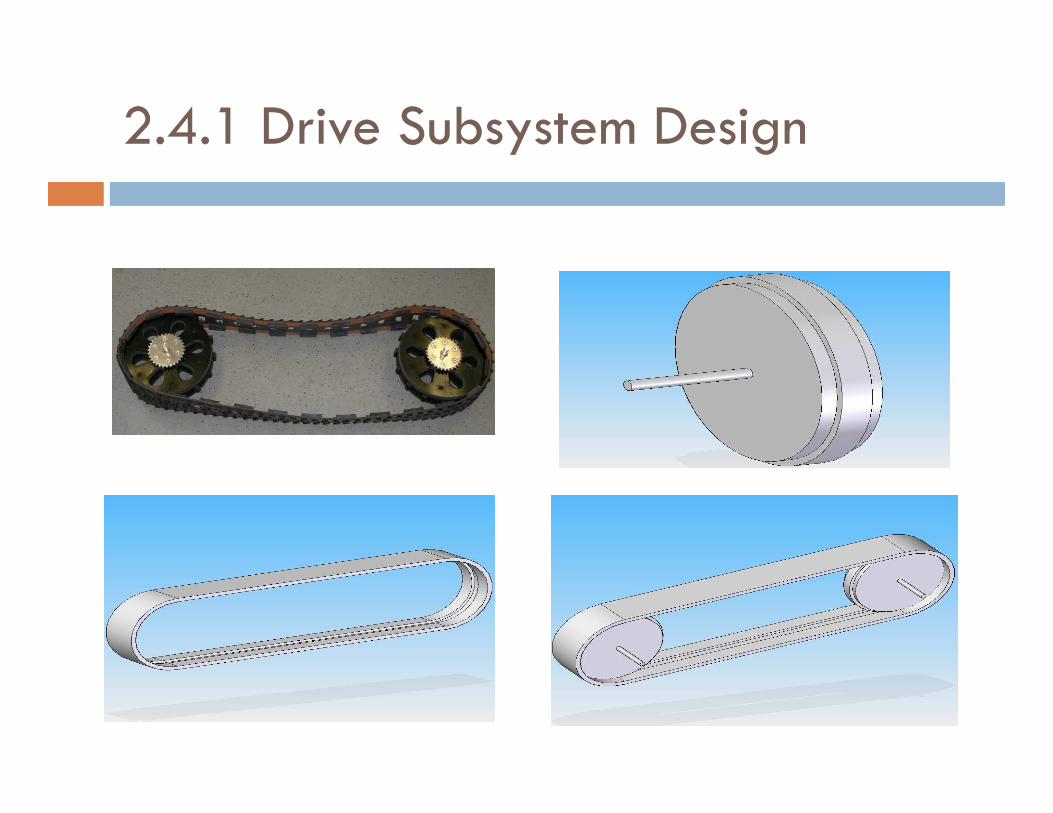
2.4.1 Drive Subsystem Design
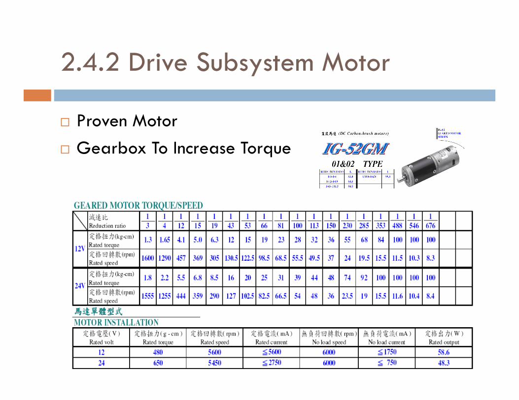
2.4.2 Drive Subsystem Motor
� Proven Motor
� Gearbox To Increase Torque
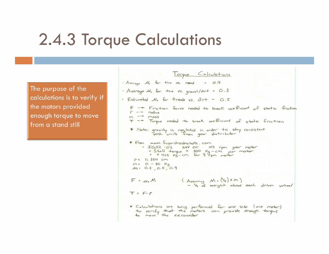
2.4.3 Torque Calculations

2.4.4 Drive Wheel Calculations
(1/4)*m Individual Drive Wheel Calculations
300
350
400
450
0
50
100
150
200
250
10 20 30 40 50 60 70 80
mass
kg-c
m
Tire vs. Road Tire vs. Gravel/Dirt Tread vs. Gravel/Dirt 008 rpm Stall Torque 103 rpm Stall Torque
Torq
ue
Kg

2.4.5 Speed Calculations
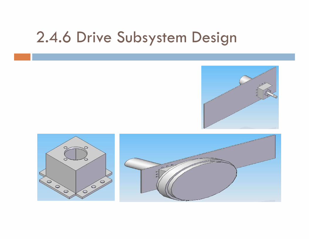
2.4.6 Drive Subsystem Design
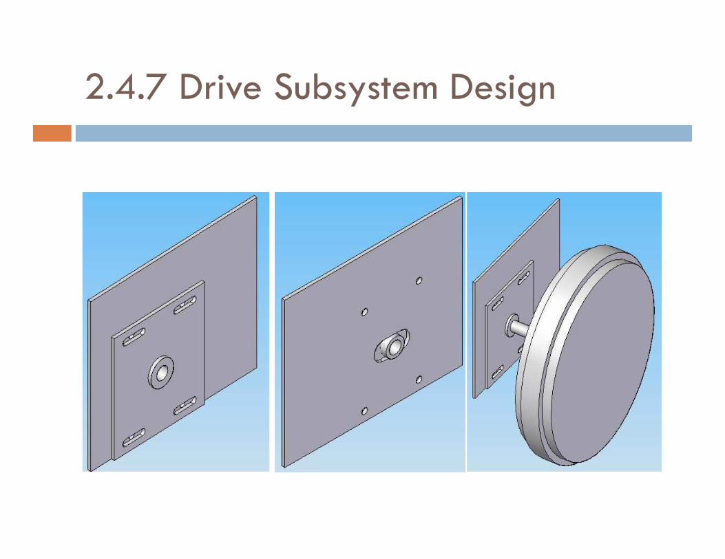
2.4.7 Drive Subsystem Design

2.4.8 Drive Subsystem Design
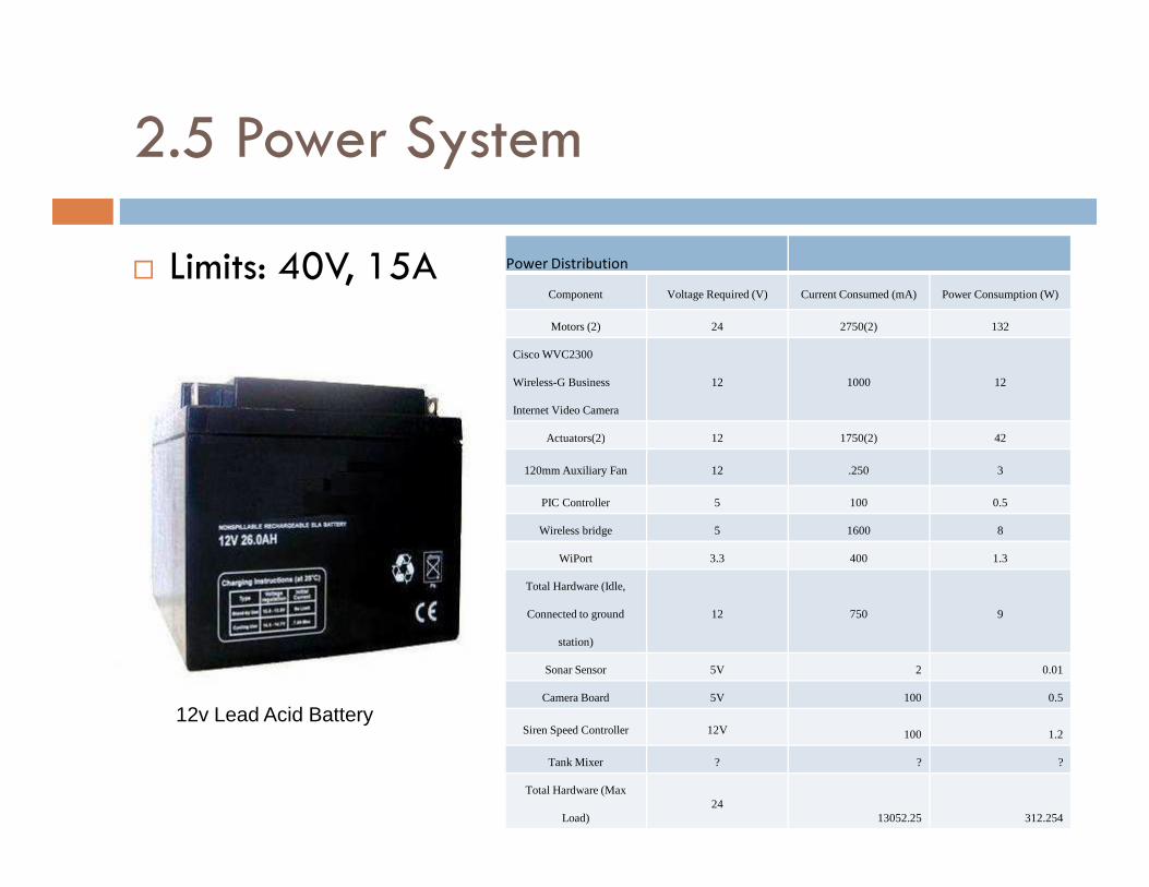
2.5 Power System
� Limits: 40V, 15A Power Distribution
Component Voltage Required (V) Current Consumed (mA) Power Consumption (W)
Motors (2) 24 2750(2) 132
Cisco WVC2300
Wireless-G Business
Internet Video Camera
12 1000 12
Actuators(2) 12 1750(2) 42Actuators(2) 12 1750(2) 42
120mm Auxiliary Fan 12 .250 3
PIC Controller 5 100 0.5
Wireless bridge 5 1600 8
WiPort 3.3 400 1.3
Total Hardware (Idle,
Connected to ground
station)
12 750 9
Sonar Sensor 5V 2 0.01
Camera Board 5V 100 0.5
Siren Speed Controller 12V 100 1.2
Tank Mixer ? ? ?
Total Hardware (Max
Load)24
13052.25 312.254
12v Lead Acid Battery
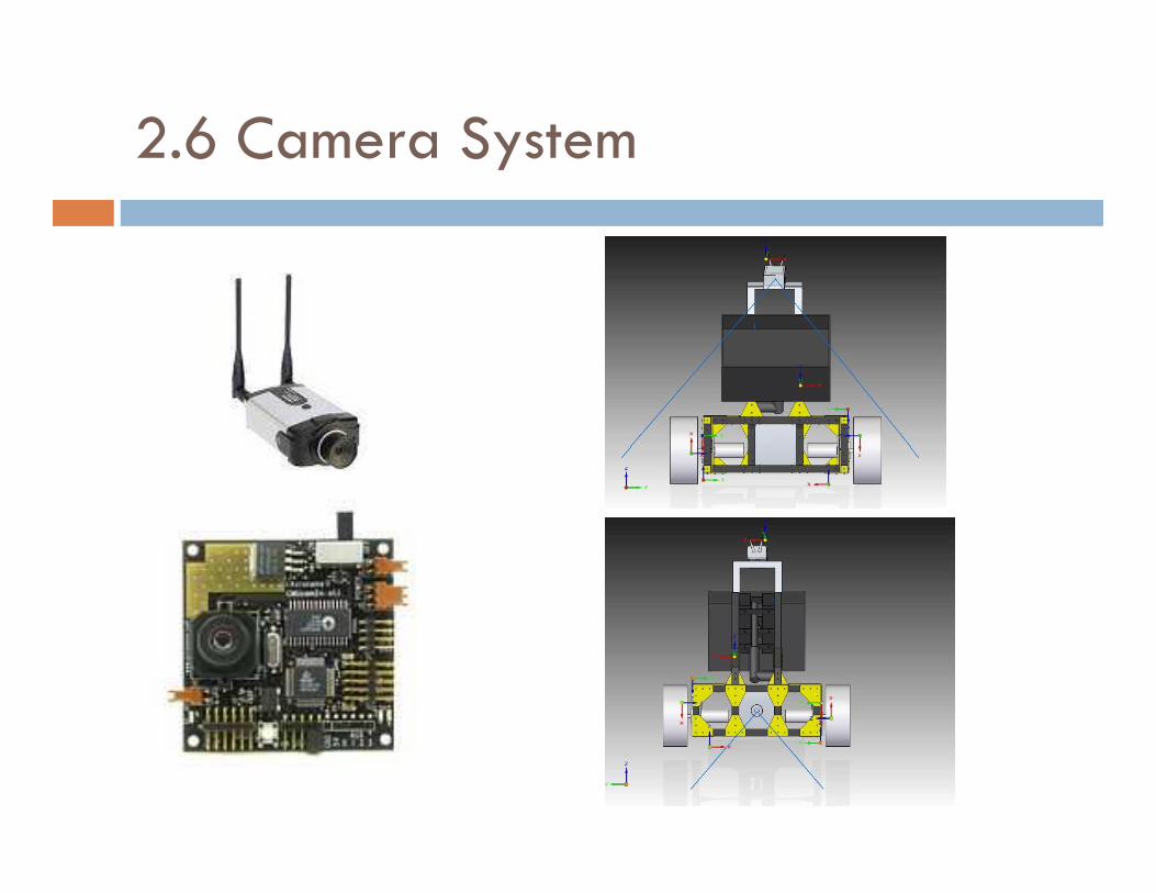
2.6 Camera System
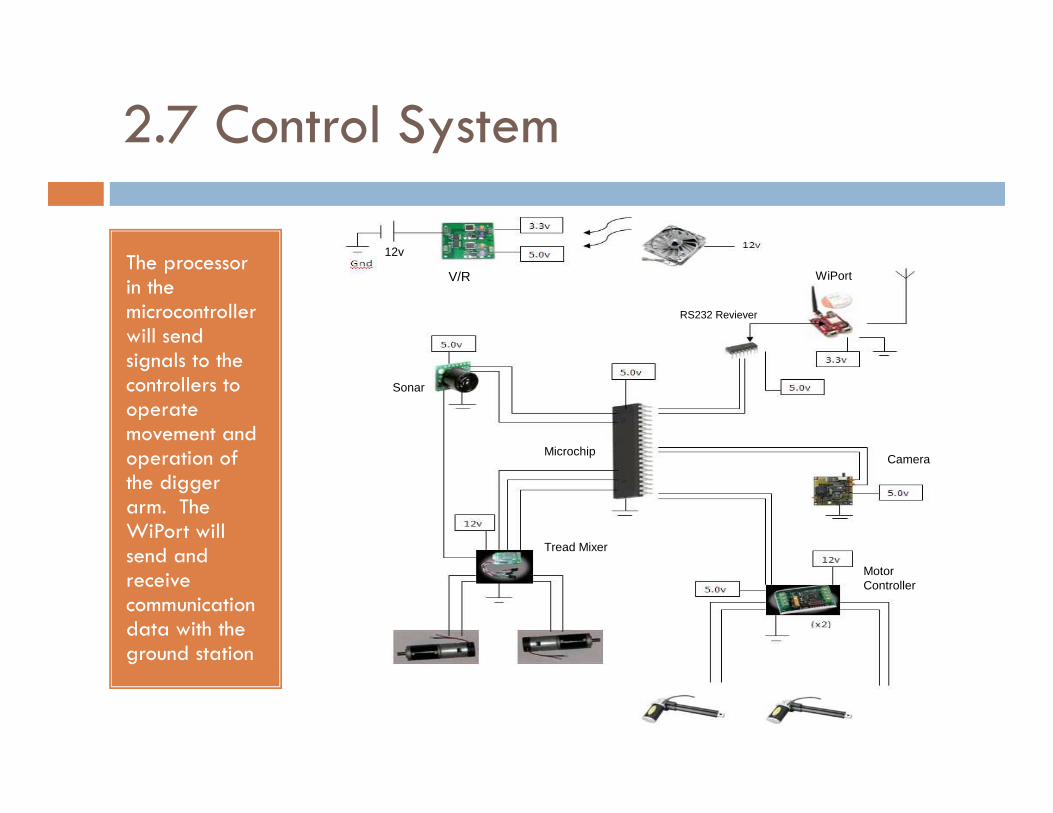
2.7 Control System
The processor in the microcontroller will send signals to the controllers to operate
V/R
12v
WiPort
Sonar
RS232 Reviever
operate movement and operation of the digger arm. The WiPort will send and receive communication data with the ground station
MicrochipCamera
Tread Mixer
MotorController
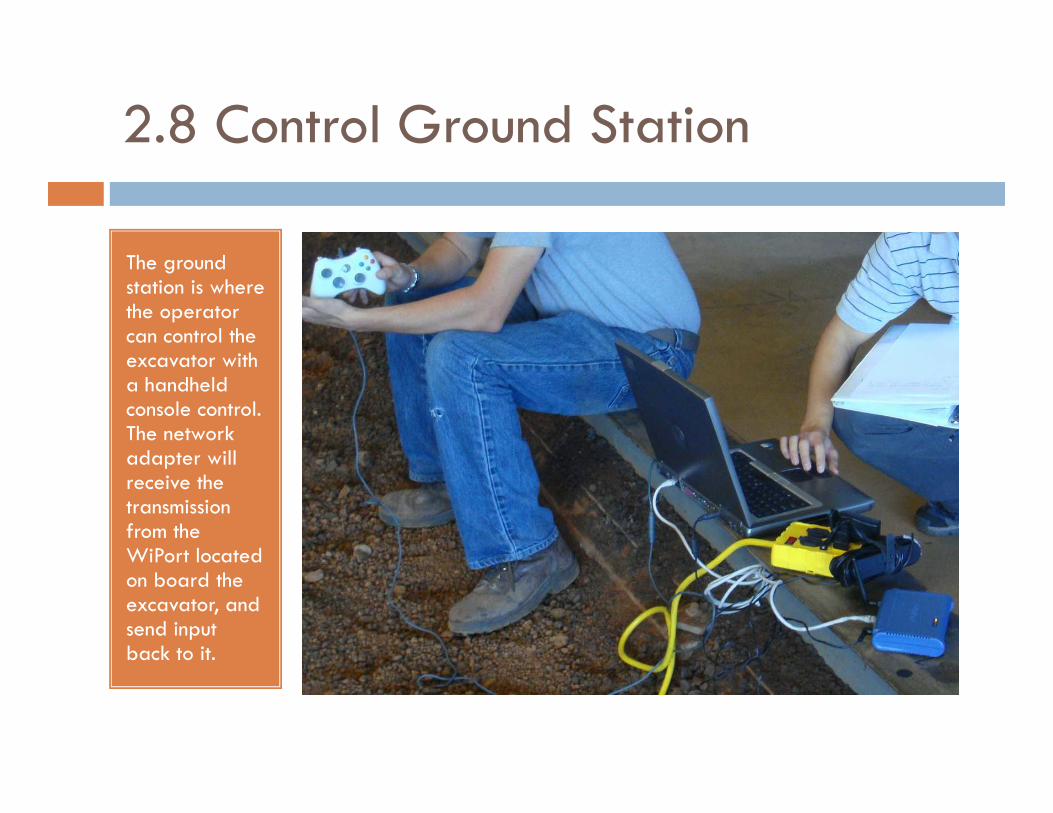
2.8 Control Ground Station
The ground station is where the operator can control the excavator with a handheld console control. console control. The network adapter will receive the transmission from the WiPort located on board the excavator, and send input back to it.
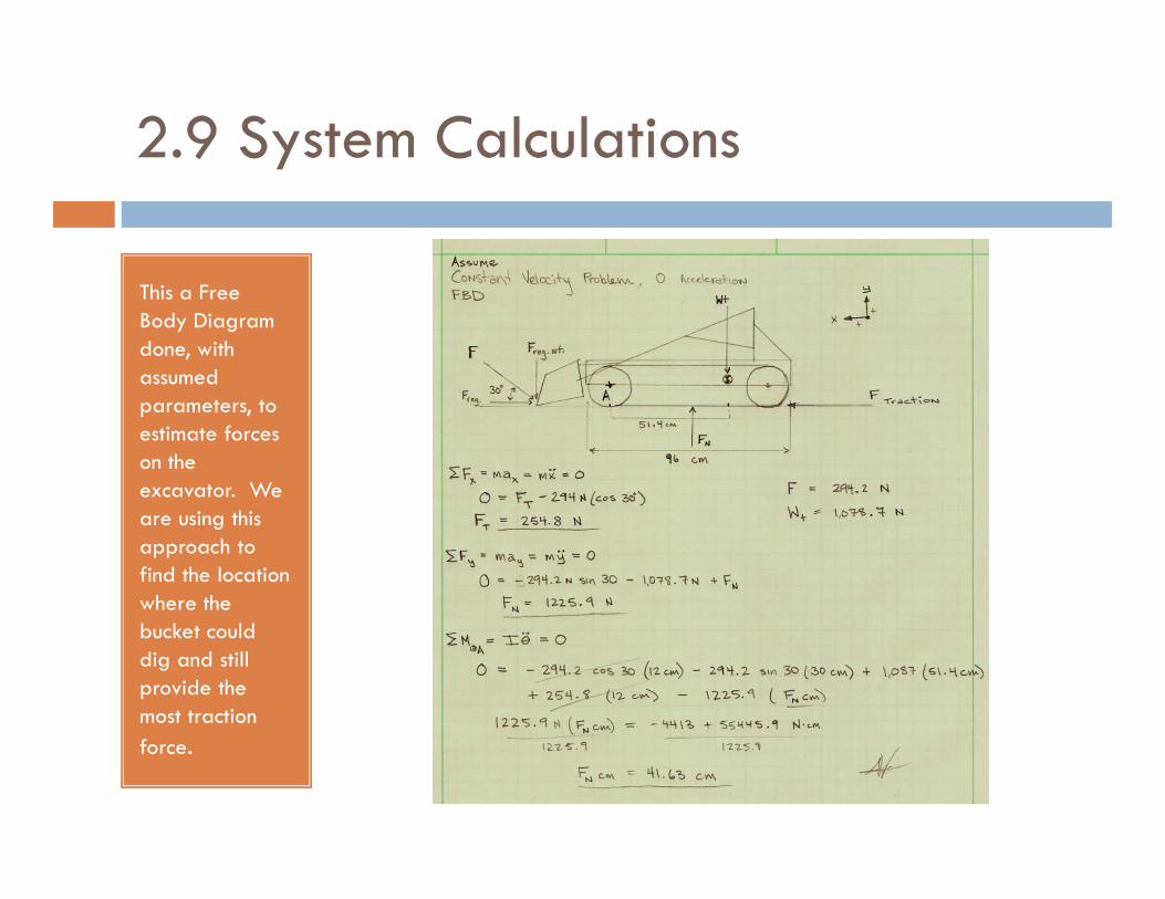
2.9 System Calculations
This a Free Body Diagram done, with assumed parameters, to estimate forces on the on the excavator. We are using this approach to find the location where the bucket could dig and still provide the most traction
force.
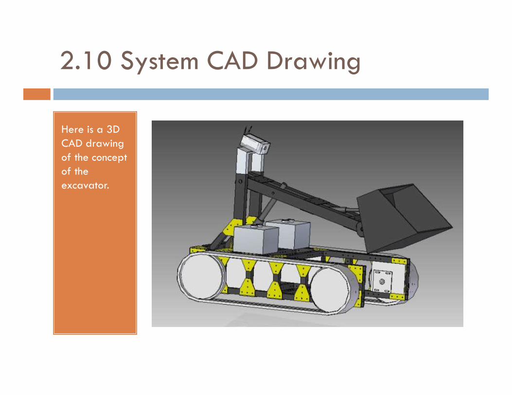
2.10 System CAD Drawing
Here is a 3D CAD drawing of the concept of the excavator.
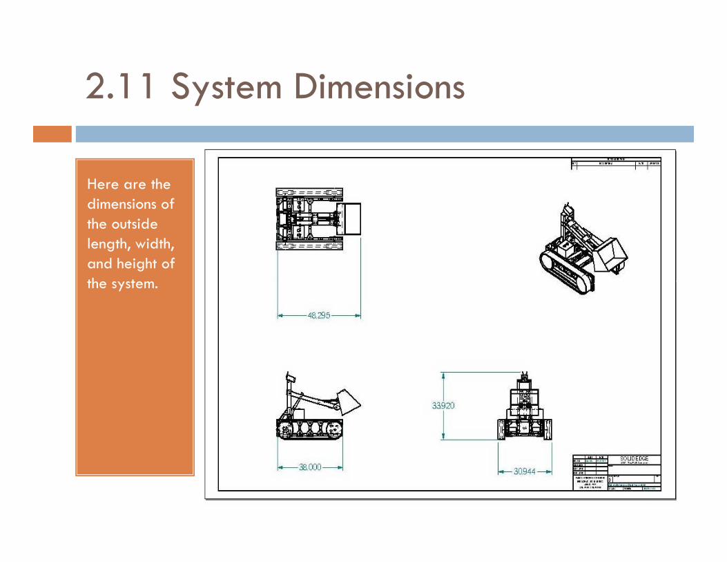
2.11 System Dimensions
Here are the dimensions of the outside length, width, and height of the system.the system.
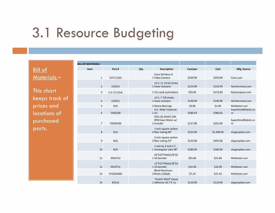
3.1 Resource Budgeting
Bill of Materials –
This chart keeps track of prices and
BILL OF MATERIALS
Item Part # Qty Description Cost/per Cost Mfg. Source
1 WVC2300 1
Cisco Wireless-G
Video Camera $359.99 $359.99 Cisco.com
2 125012 1
12 V, 11 13/16 stroke
linear Actuator $159.99 $159.99 Northerntool.com
3 LA-12v26ah 2 12v Lead acid battery $59.95 $119.90 batteryspace.com
4 125011 1
12 V, 7 7/8 stroke
linear actuator $149.99 $149.99 Northerntool.com
5 N/A 2 Sleeve Bearings $0.80 $1.60 McMaster-carrprices and locations of purchased parts.
5 N/A 2 Sleeve Bearings $0.80 $1.60 McMaster-carr
6 TD05200 1
4 in. Wide Tread set
(2) $580.63 $580.63
SuperDroidRobots.co
m
7 TD036290 2
IG52-02 24VDC 290
RPM Gear Motor w/
encoder $127.80 $255.60
SuperDroidRobots.co
m
8 N/A 4
1 inch square carbon
fiber tubing 96" $325.00 $1,300.00 dragonplate.com
9 N/A 3
2 inch square carbon
fiber tubing 24" $150.00 $450.00 drgaonplate.com
10 N/A 1
1 inch by 2 inch C.F.
rectangular tube 48" $180.00 $180.00 dragonplate.com
11 9910T22 1
24"X24"Plate(1/8")G-
10 Garolite $55.86 $55.86 McMaster-carr
12 9910T21 1
12"X12"Plate(1/8")G-
10 Garolite $16.90 $16.90 McMaster-carr
13 97526A404 3
Blind Aluminum
Rivets (100pk) $7.14 $21.42 McMaster-carr
14 #2216 1
"Scotch-Weld" Epoxy
Adhesive 26.7 fl. oz $119.00 $119.00 drgaonplate.com

3.2 Resource Budgeting(Continued)
Bill of Materials –
This chart keeps track of prices and
BILL OF MATERIALS
15 6659A21 1
Blind Rivet
Installation Tool $25.18 $25.18 McMaster-carr
16 N/A 1 1/4" x 3/4" fasteners $1.00 $1.00 N/A
17 N/A 1 1/2"x18" Shaft $25.08 $25.08 McMaster-carr
18 N/A Aluminum Sheet $0.00 N/A
19 DVREG 1
Dual 5v +3.3v
Switching Voltage
Regulator $74.95 $74.95 Roboticsconnectionprices and locations of purchased parts.
19 DVREG 1 Regulator $74.95 $74.95 Roboticsconnection
20 SK 3720Q1 1
CMUCam2+ robot
camera $169.96 $169.96 Roboticsconnection
21 EZ3LV 1
Maxbotix Maxsonar-
EZ3 Sensor $24.95 $24.95 Roboticsconnection
22 130898 1
Aerocool Turbine
1000 silver 120mm
Fan $14.99 $14.99 xoxide.com
23 RL-IMX1 1
IMX-1 Invertable RC
tank mixer $39.95 $39.95 Robotcombat.com
24 0-SYREN10 2
SyRen 10A
Regenerative Motor
Driver $49.99 $99.98 Robotcombat.com
25 17M0994 2
PIC18LF4682-I/P 8-bit
Microcontroller $8.35 $16.70 Microchip.com
26 N/A 1
Lantronix WiPort Eval
kit $299.99 $299.99 Lantronix.com
27 MAX232ECN 2
TXInst. RS-232 Line
Driver/Reciever $0.86 $1.72 Mouser electronics
$0.00
Total Cost $4,565.33
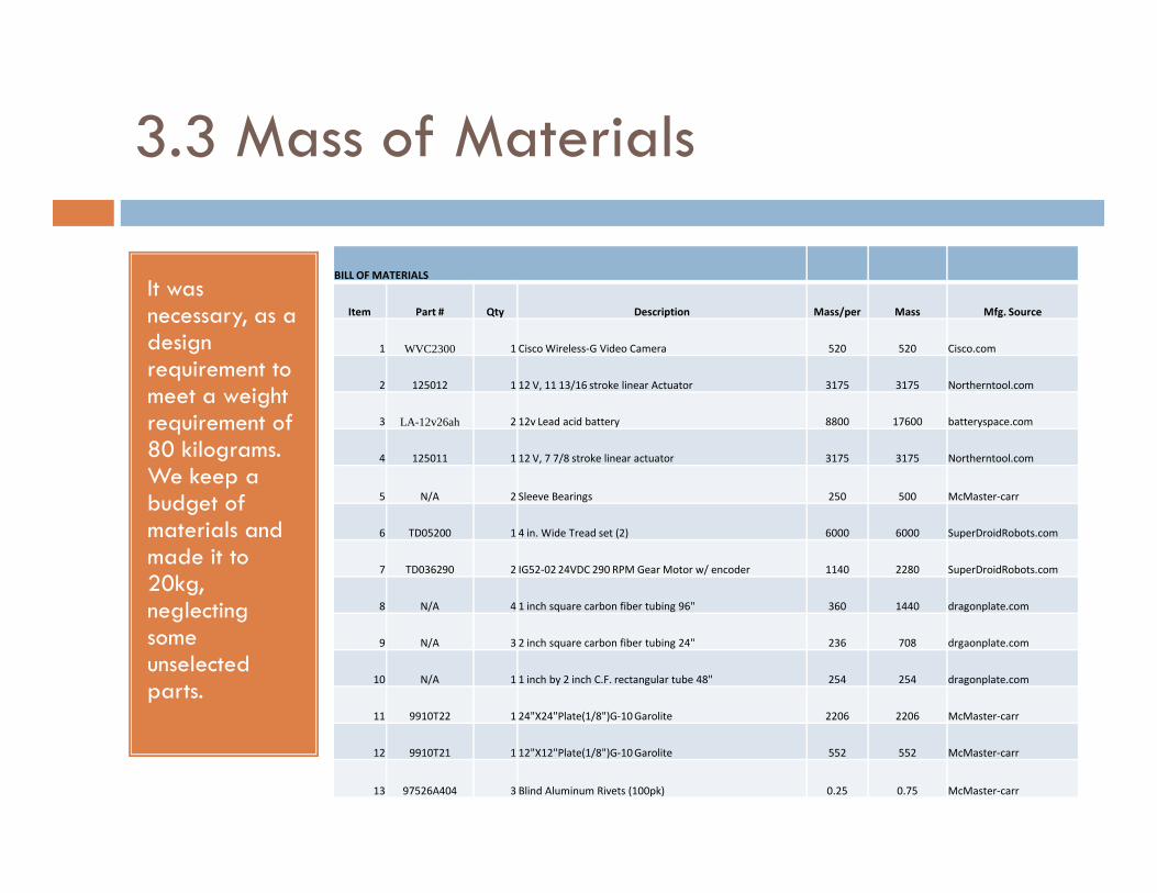
3.3 Mass of Materials
It was necessary, as a design requirement to meet a weight requirement of 80 kilograms.
BILL OF MATERIALS
Item Part # Qty Description Mass/per Mass Mfg. Source
1 WVC2300 1 Cisco Wireless-G Video Camera 520 520 Cisco.com
2 125012 1 12 V, 11 13/16 stroke linear Actuator 3175 3175 Northerntool.com
3 LA-12v26ah 2 12v Lead acid battery 8800 17600 batteryspace.com
80 kilograms. We keep a budget of materials and made it to 20kg, neglecting some unselected parts.
4 125011 1 12 V, 7 7/8 stroke linear actuator 3175 3175 Northerntool.com
5 N/A 2 Sleeve Bearings 250 500 McMaster-carr
6 TD05200 1 4 in. Wide Tread set (2) 6000 6000 SuperDroidRobots.com
7 TD036290 2 IG52-02 24VDC 290 RPM Gear Motor w/ encoder 1140 2280 SuperDroidRobots.com
8 N/A 4 1 inch square carbon fiber tubing 96" 360 1440 dragonplate.com
9 N/A 3 2 inch square carbon fiber tubing 24" 236 708 drgaonplate.com
10 N/A 1 1 inch by 2 inch C.F. rectangular tube 48" 254 254 dragonplate.com
11 9910T22 1 24"X24"Plate(1/8")G-10 Garolite 2206 2206 McMaster-carr
12 9910T21 1 12"X12"Plate(1/8")G-10 Garolite 552 552 McMaster-carr
13 97526A404 3 Blind Aluminum Rivets (100pk) 0.25 0.75 McMaster-carr
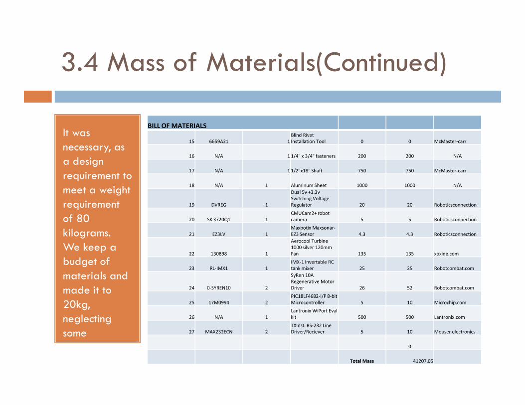
3.4 Mass of Materials(Continued)
It was necessary, as a design requirement to meet a weight requirement
BILL OF MATERIALS
15 6659A21 1
Blind Rivet
Installation Tool 0 0 McMaster-carr
16 N/A 1 1/4" x 3/4" fasteners 200 200 N/A
17 N/A 1 1/2"x18" Shaft 750 750 McMaster-carr
18 N/A 1 Aluminum Sheet 1000 1000 N/A
19 DVREG 1
Dual 5v +3.3v
Switching Voltage
Regulator 20 20 Roboticsconnectionrequirement of 80 kilograms. We keep a budget of materials and made it to 20kg, neglecting some unselected parts.
19 DVREG 1 Regulator 20 20 Roboticsconnection
20 SK 3720Q1 1
CMUCam2+ robot
camera 5 5 Roboticsconnection
21 EZ3LV 1
Maxbotix Maxsonar-
EZ3 Sensor 4.3 4.3 Roboticsconnection
22 130898 1
Aerocool Turbine
1000 silver 120mm
Fan 135 135 xoxide.com
23 RL-IMX1 1
IMX-1 Invertable RC
tank mixer 25 25 Robotcombat.com
24 0-SYREN10 2
SyRen 10A
Regenerative Motor
Driver 26 52 Robotcombat.com
25 17M0994 2
PIC18LF4682-I/P 8-bit
Microcontroller 5 10 Microchip.com
26 N/A 1
Lantronix WiPort Eval
kit 500 500 Lantronix.com
27 MAX232ECN 2
TXInst. RS-232 Line
Driver/Reciever 5 10 Mouser electronics
0
Total Mass 41207.05
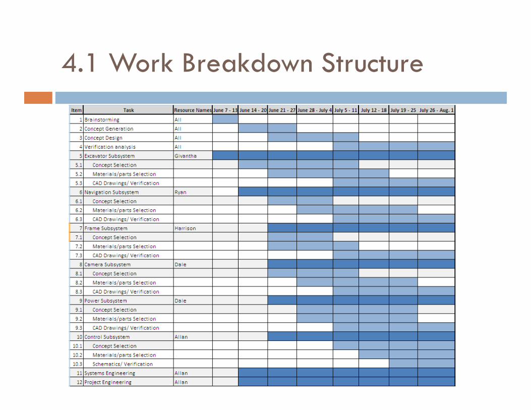
4.1 Work Breakdown Structure
5.0 Conclusion and Future Goals
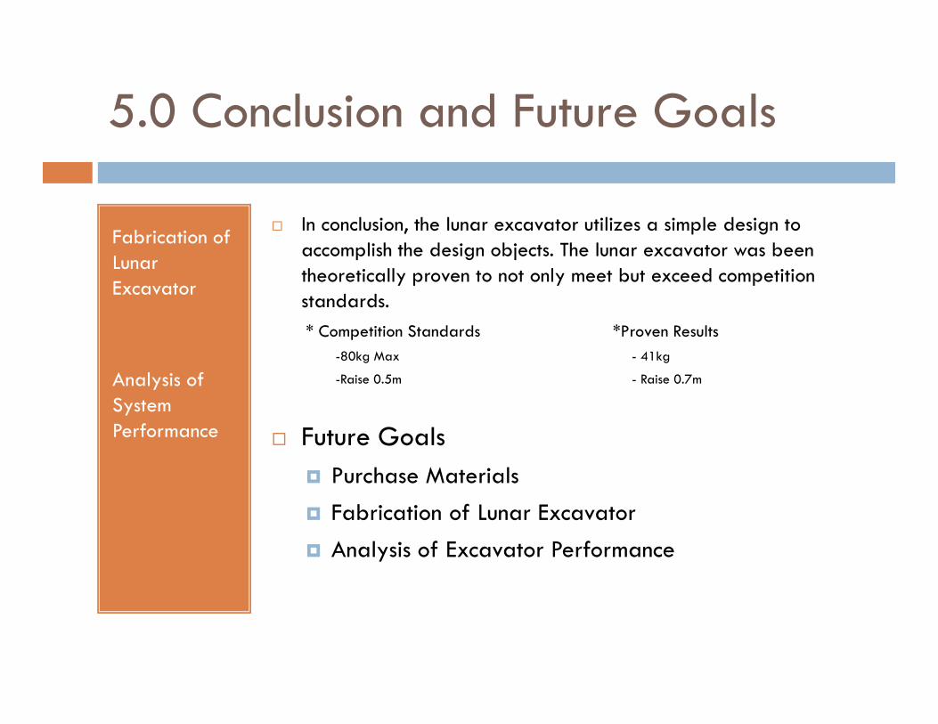
Fabrication of Lunar Excavator
� In conclusion, the lunar excavator utilizes a simple design to accomplish the design objects. The lunar excavator was been theoretically proven to not only meet but exceed competition standards.
* Competition Standards *Proven Results
-80kg Max - 41kg
Analysis of System Performance
-80kg Max - 41kg
-Raise 0.5m - Raise 0.7m
� Future Goals
� Purchase Materials
� Fabrication of Lunar Excavator
� Analysis of Excavator Performance


