Version 03
951-170-235-EN
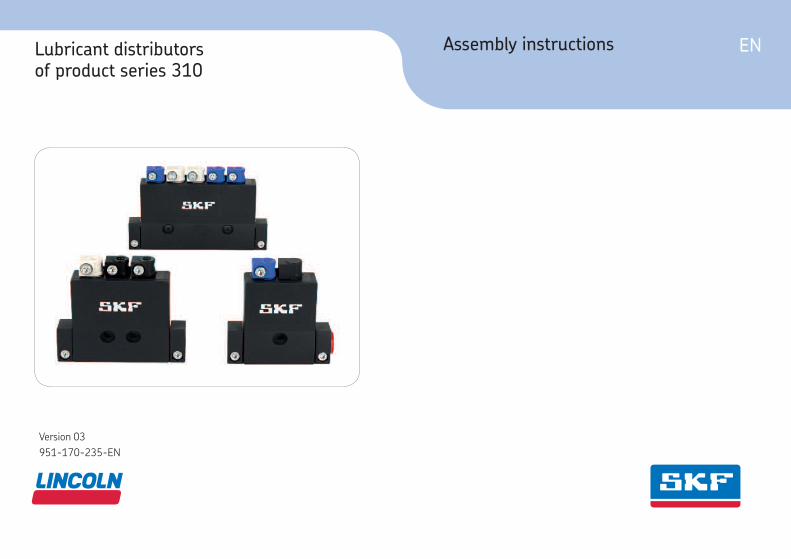
ENAssembly instructionsLubricant distributors of product series 310

- 2 -951-170-235-EN
Version 03

- 3 - 951-170-235-EN
Version 03
ENMasthead
Training
SKF conducts detailed training in order to
enable the maximum safety and efficiency.
SKF recommends taking advantage of this
training. For information, contact the rel-
evant SKF service address.
Copyright
© Copyright SKF
All rights reserved.
Warranty
The instructions do not contain any infor-
mation on the warranty. This can be found in
our General Terms and Conditions.
Disclaimer of liability
The manufacturer shall not be held liable for
damage resulting from:
○ Improper usage, assembly, operation,
configuration, maintenance, repair, or
accidents
○ Improper reaction to malfunctions
○ Unauthorized modifications to the
product
○ Intentional or gross negligence
○ Use of non-original
SKF spare parts
The maximum liability for loss or damage
resulting from the use of our products is
limited to the purchase price. Liability for
indirect damage of any kind is excluded.
Masthead
Manufacturer
SKF Lubrication Systems Germany GmbH
Address of manufacturer plants
Headquarters
Walldorf Plant
Heinrich-Hertz-Str. 2-8
69190 Walldorf
Germany
Tel: +49 (0) 6227 33-0
Fax: +49 (0) 6227 33-259
Berlin Plant
Motzener Straße 35/37
12277 Berlin
Germany
Tel. +49 (0)30 72002-0
Fax +49 (0)30 72002-111
Hockenheim Plant
2. Industriestraße 4
68766 Hockenheim
Germany
Tel. +49 (0)62 05 27-0
Fax +49 (0)62 05 27-101
E-mail: [email protected]
www.skf.com/lubrication
- 4 -951-170-235-EN
Version 03
EN Table of contents
Table of contents
Masthead .................................................................................................... 3
Explanation of symbols and signs .............................................................. 6
1. Safety instructions ........................................................................ 8
1.1 General safety instructions ....................................................................81.2 General behavior when handling the product .....................................81.3 Intended use ............................................................................................91.4 Foreseeable misuse ................................................................................91.5 Painting plastic components ...............................................................101.6 Modifications to the product ................................................................101.7 Prohibition of certain activities ...........................................................101.8 Inspections prior to delivery ................................................................101.9 Referenced documents ........................................................................101.10 Notes on the rating plate .....................................................................111.11 Note on Pressure Equipment Directive 2014/68/EU ......................111.12 Persons authorized to use the product ..............................................11
1.12.1 Operator ...........................................................................................111.12.2 Qualified mechanic .........................................................................121.12.3 Instruction of outside fitters ..........................................................12
1.13 Provision of personal protective gear .................................................121.14 Operation ...............................................................................................121.15 Emergency shutdown ..........................................................................121.16 Transport, assembly, maintenance, malfunction, repair, shutdown, disposal ...............................................................................121.17 Initial commissioning, daily startup ....................................................141.18 Cleaning .................................................................................................141.19 Residual risks ........................................................................................14
2. Lubricants ................................................................................... 15
2.1 General information .............................................................................152.2 Selection of lubricants ..........................................................................152.3 Material compatibility ...........................................................................162.4 Aging of lubricants ................................................................................16
3. Overview, functional description ................................................ 17
3.1 Components of product series 310 ....................................................173.2 General ...................................................................................................183.3 Operation of lubricant distributors of product series 310 ...............18
4. Technical data ............................................................................. 20
4.1 General technical data ..........................................................................204.2 Product code..........................................................................................21
5. Delivery, returns, storage ........................................................... 22
5.1 Delivery ..................................................................................................225.2 Return shipment ..................................................................................225.3 Storage ...................................................................................................22

- 5 - 951-170-235-EN
Version 03
ENTable of contents
6. Assembly ..................................................................................... 23
6.1 General information .............................................................................236.2 Assembly location .................................................................................236.3 Mechanical connection .........................................................................23
6.3.1 Minimum mounting dimensions ..................................................236.3.2 Assembly holes ...............................................................................23
6.4 Assembly of a 2-port lubricant distributor ........................................246.5 Assembly of a 3-or 5-port lubricant distributor ...............................256.6 Connect the lubricant line ....................................................................27
6.6.1 Assembly process ...........................................................................286.7 Venting the lubricant distributors .......................................................31
6.7.1 Venting procedure for main lubricant lines .................................316.7.2 Venting procedure for lubricant distributor and lubrication point lines .....................................................................32
7. Initial commissioning .................................................................. 33
7.1 Inspections before initial commissioning ...........................................337.2 Inspections during initial commissioning ...........................................33
8. Operation .................................................................................... 34
9. Cleaning ...................................................................................... 34
9.1 Cleaning agents.....................................................................................349.2 Exterior cleaning ...................................................................................349.3 Interior cleaning ....................................................................................34
10. Maintenance ............................................................................... 35
11. Malfunctions, causes, and remedies .......................................... 36
12. Repairs ........................................................................................ 36
13. Shutdown, disposal .................................................................... 37
13.1 Temporary shutdown ...........................................................................3713.2 Permanent shutdown, disassembly ...................................................3713.3 Disposal ..................................................................................................37
14. Accessories ................................................................................. 38
14.1 Plugs/clamp connections .....................................................................3814.2 Plastic tubing .........................................................................................38

- 6 -951-170-235-EN
Version 03
EN Explanation of symbols, signs, and abbreviations
Explanation of symbols and signs
General warning Risk of slipping Pressure injection
Wear personal protective gear (gloves)
Disposal, recyclingUnauthorized persons must be kept away.
Wear personal protective gear (protective clothing)
Wear personal protective gear (goggles)
Wear personal protective gear (face mask)
General notesWear personal protective gear (protective footwear)
Warning level Consequence Probability Symbol Meaning
DANGERDeath, serious injury
Immediate Chronological instructions
WARNING Serious injury Possible Bullet list items
CAUTIONMinor injury
Possible Indicates requirements for the action
IMPORTANT NOTE Property damage Possible Refers to other facts, causes, or consequences

- 7 - 951-170-235-EN
Version 03
ENExplanation of symbols, signs, and abbreviations
Abbreviations and conversion factors
re regarding °C degrees Celsius °F degrees Fahrenheitapprox. approximately K Kelvin Oz. ouncei.e. that is N Newton fl. oz. Fluid ounceetc. et cetera h hour in. inchposs. possibly s second psi pound per square inchincl. including d day sq.in. square inchmin. minimum Nm Newton meter cu. in. cubic inchmax. maximum ml milliliter mph miles per hourmin minute ml/d milliliters per day RPM revolutions per minuteetc. et cetera ccm cubic centimeter gal. Gallone.g. for example mm millimeter lb. poundkW kilowatt l liter hp horsepowerU voltage db (A) sound pressure level kp kilopoundR Resistance > greater than fpsec feet per secondI current intensity < less than Conversion factorsV volt ± plus minus Length 1 mm = 0.03937 in.W watt Ø diameter Area 1 cm² = 0.155 sq.inAC alternating current kg kilogram Volume 1 ml = 0.0352 fl.oz.DC direct current RH relative humidity 1 l = 2.11416 pints (US)A ampere ≈ approximately Mass 1 kg = 2.205 lbsAh ampere hour = equal to 1 g = 0.03527 oz.Hz Frequency (Hertz) % percent Density 1 kg/cm³ = 8.3454 lb./gal(US)NC normally closed contact ‰ per mil (thousandth) 1 kg/cm³ = 0.03613 lb./cu.in.NO normally open contact ≥ greater or equal Force 1 N = 0.10197 kp
≤ less or equal Pressure 1 bar = 14.5 psimm2 square millimeter Temperature °C = (°F-32) x 5/9RPM revolutions per minute Power 1 kW = 1.34109 hp
Acceleration 1 m/s² = 3.28084 ft./s²
Speed 1 m/s = 3.28084 fpsec.
1 m/s = 2.23694 mph

- 8 -951-170-235-EN
Version 03
EN 1. Safety instructions
1. Safety instructions
1.1 General safety instructions
○ The operator must ensure that the in-
structions are read by all persons tasked
with working on the product or who
supervise or instruct such persons. The
operator must also ensure that the staff
fully understands the content of the in-
structions. Putting the products into op-
eration or operating them without having
read the instructions is prohibited.
○ Retain the instructions for further use.
○ The products described here were
manufactured according to the state of
the art. Risks may, however, arise from
non-compliant usage and may result in
personal injury or damage to material
assets.
○ Any malfunctions which may affect safety
must be remedied immediately. In ad-
dition to these instructions, the statu-
tory regulations for accident prevention
and environmental protection must be
observed.
○ Responsibilities for different activities
must be clearly defined and observed.
Uncertainty seriously endangers safety.
○ Protective and safety mechanisms must
not be removed, modified, nor disabled
during operation and must be checked
for proper function and completeness at
regular intervals.
○ If protective and safety mechanisms
must be removed, they must be rein-
stalled immediately following conclusion
of work and then inspected for proper
function.
○ Any malfunctions that occur must be
resolved according to responsibility. The
supervisor must be notified immediately
in case of malfunctions outside one's in-
dividual scope of responsibility.
1.2 General behavior when handling the product
○ The product may only be used in aware-
ness of the potential dangers, in proper
technical condition, and according to the
information in this manual.
○ Familiarize yourself with the functions
and operation of the product. The speci-
fied assembly and operating steps and
their sequences must be observed.
○ Any unclear points regarding proper
condition or correct assembly/operation
must be clarified. Operation is prohibited
until issues have been clarified.
○ Unauthorized persons must be kept
away.
○ Wear personal protective equipment.
○ All safety regulations and in-house
instructions relevant to the particular
activity must be observed.

1
- 9 - 951-170-235-EN
Version 03
EN1. Safety instructions
1.3 Intended use
Feed lubricants only in compliance with the
specifications, technical data, and limits pre-
sented in this manual.
The SKF lubricant distributor of product se-
ries 310 is designed for the metering of fluid
greases up to NLGI grade 000-00 and oils
of 20 – 1500 mm2/s in a single-line central-
ized lubrication system. The permissible
operating pressure of the 310 distributor is
between 12 and 38 bar. The relief pressure
is 3 bar. The lubricant used must be suitable
for elastomers (FKM (FPM)).
The technical requirements for the instal-
lation of the 310 lubricant distributor are
set out in Chapter 6, “Assembly.” These
requirements must be complied with. The
same applies to the technical specifications
in Chapter 4.
Usage is permitted exclusively in the context
of commercial or business activity by profes-
sional users.
1.4 Foreseeable misuse
Any usage of the product other than as
specified in this manual is strictly prohibited.
Particularly prohibited are:
○ Use outside the specified pressure range
○ Use outside the specified operating tem-
perature range
○ Use of non-specified equipment
○ Use in areas with aggressive, corrosive
substances (e.g., high ozone loads)
○ in areas with damaging radiation (e.g.,
ionizing radiation)
○ Use to feed, forward, or store hazardous
substances and mixtures as defined in
Annex I Part 2-5 of the CLP Regulation
(EC 1272/2008) that are marked with
hazard pictograms GHS01-GHS 09
○ Use to feed / forward / store gases,
liquefied gases, dissolved gases, va-
pors, or fluids whose vapor pressure
exceeds normal atmospheric pressure
(1013 mbar) by more than 0.5 bar at
their maximum permissible operating
temperature
○ Use in an explosion protection zone

- 10 -951-170-235-EN
Version 03
EN 1. Safety instructions
1.8 Inspections prior to delivery
The following tests were performed prior to
delivery:
○ Safety and functional tests
1.9 Referenced documents
In addition to this manual, the following
documents must be observed by the re-
spective target group:
○ Operational instructions, approval rules
○ The safety data sheet of the lubricant
used
If necessary:
○ Project planning documents
○ Instructions for other components for
setting up the centralized lubrication
system
○ Other relevant documents for integration
of the product into the main machine,
system
1.5 Painting plastic components
The painting of all plastic components and
seals of the products described here is pro-
hibited.
1.6 Modiications to the product
Unauthorized modifications and changes
can have an unpredictable effect on safety.
Unauthorized modifications and changes
are therefore prohibited.
1.7 Prohibition of certain activities
The following activities must be performed
only by employees of the manufacturer or
authorized persons due to possibly unde-
tectable sources of error or due to statutory
requirements:
○ Operation of the distributor in an incom-
pletely assembled condition (e.g., missing
lid)

1
- 11 - 951-170-235-EN
Version 03
EN1. Safety instructions
1.10 Notes on the rating plate
The rating plate is firmly con-
nected to the distributor body
and the lid. Removing the lid
results in destruction of the rat-
ing plate.
The rating plate provides important data
such as the product code and serial number.
To avoid loss of this data in case the rating
plate becomes illegible, these characteristics
should be entered in the manual.
SKF Lubrication Systems Germany GmbHDE 12277 Berlin
distributorlubricant
Product code: ___________________________________
Serial number: ___________________________________
1.11 Note on Pressure Equipment Directive 2014/68/EU
Due to its performance characteristics, the
product does not reach the limit values
defined in Article 4, Paragraph 1, Subpara-
graph (a) item (i) and is, pursuant to Article
4, Paragraph 3, excluded from the scope of
Pressure Equipment Directive 2014/68/EU.
1.12 Persons authorized to use the product
1.12.1 Operator
A person competent due to training, knowl-
edge, and experience to execute the func-
tions and activities associated with normal
operation; this also includes the avoidance
of possible hazards that may arise during
operation.
Product code
Serial number
- 12 -951-170-235-EN
Version 03
EN 1. Safety instructions
1.15 Emergency shutdown
Shut down the product in an emergency by:
○ Switching off the main machine in which
the product is integrated
○ If necessary, pressing the on/off switch
on the main machine
1.16 Transport, assembly, maintenance, malfunction, repair, shutdown, disposal
○ All relevant persons must be informed of
the activity prior to the start of this work.
Precautionary
operational measures, work instructions
must be observed.
○ Maintenance and repair work can be
subject to restrictions at low or high tem-
peratures (e.g., altered flow properties
of the lubricant). Maintenance and repair
1.13 Provision of personal protective gear
The operator must provide personal protec-
tive gear appropriate for the location and
intended application.
1.14 Operation
The following must be observed during
commissioning and operation:
○ All information within this manual and
all information within the referenced
documents
○ All laws and regulations that the operator
must observe
1.12.2 Qualiied mechanic
A person with appropriate technical train-
ing, knowledge, and experience who can
recognize and avoid the hazards that may
occur during transport, assembly, commis-
sioning, operation, maintenance, repair, and
dismantling
1.12.3 Instruction of outside itters
Before commencing work, the operator
must inform outside fitters of the opera-
tional safety regulations, applicable accident
prevention regulations, and the functions of
the main machine and its protective devices.

1
- 13 - 951-170-235-EN
Version 03
EN1. Safety instructions
work should therefore preferably be per-
formed at room temperature.
○ Prior to performing work, the product
and the machine in which the product
will be integrated must be de-energized,
depressurized, and secured against un-
authorized activation.
○ Take appropriate measures to ensure
that moving, detached parts are im-
mobilized during the work and that no
limbs can be pinched by unintended
movements.
○ Assemble the product only outside the
operating range of moving parts, at an
adequate distance from sources of heat
or cold. Other units of the machine, the
vehicle must not be damaged or impaired
in their function by the installation.
○ Dry any wet, slippery surfaces or cover
appropriately.
○ Cover hot or cold surfaces appropriately.
○ Drill required holes only on non-critical,
non-load-bearing parts. Use existing
boreholes. Do not damage lines or cables
when drilling.
○ Observe any possible wearing spots. Pro-
tect components appropriately.
○ All components used must be designed
for:
- The maximum operating pressure
- The maximum/minimum ambient tem-
perature
- The lubricant to be delivered.
○ No parts may be subjected to torsion,
shear, or bending.
○ Check parts for contamination before use
and clean if necessary.
○ Lubricant lines should be filled with lu-
bricant prior to assembly. This simplifies
subsequent venting of the system.
○ Adhere to the specified torques. Use
a calibrated torque wrench when
tightening.
○ Avoid mixing up/incorrectly assembling
disassembled parts. Label parts.
- 14 -951-170-235-EN
Version 03
EN 1. Safety instructions
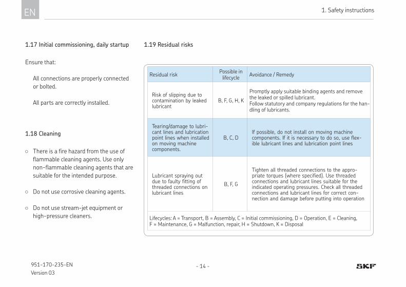
1.19 Residual risks
Residual riskPossible in lifecycle
Avoidance / Remedy
Risk of slipping due to contamination by leaked lubricant
B, F, G, H, K
Promptly apply suitable binding agents and remove the leaked or spilled lubricant.Follow statutory and company regulations for the han-dling of lubricants.
Tearing/damage to lubri-cant lines and lubrication point lines when installed on moving machine components.
B, C, DIf possible, do not install on moving machine components. If it is necessary to do so, use flex-ible lubricant lines and lubrication point lines
Lubricant spraying out due to faulty fitting of threaded connections on lubricant lines
B, F, G
Tighten all threaded connections to the appro-priate torques (where specified). Use threaded connections and lubricant lines suitable for the indicated operating pressures. Check all threaded connections and lubricant lines for correct con-nection and damage before putting into operation
Lifecycles: A = Transport, B = Assembly, C = Initial commissioning, D = Operation, E = Cleaning, F = Maintenance, G = Malfunction, repair, H = Shutdown, K = Disposal
1.17 Initial commissioning, daily startup
Ensure that:
¹ All connections are properly connected
or bolted.
¹ All parts are correctly installed.
1.18 Cleaning
○ There is a fire hazard from the use of
flammable cleaning agents. Use only
non-flammable cleaning agents that are
suitable for the intended purpose.
○ Do not use corrosive cleaning agents.
○ Do not use stream-jet equipment or
high-pressure cleaners.

2
- 15 - 951-170-235-EN
Version 03
EN2.Lubricants
2. Lubricants
2.1 General information
Lubricants are used specially for specific
applications. To fulfill the task, lubricants
must meet various requirements to varying
degrees. The most important requirements
for lubricants are:
○ Reduction in friction and wear
○ Corrosion protection
○ Noise reduction
○ Protection against contamination/
ingress of foreign matter
○ Cooling (primarily for oils)
○ Durability (physical/chemical stability)
○ Compatible with as many materials as
possible
○ Economic and environmental aspects
2.2 Selection of lubricants
SKF Lubrication Systems considers lubri-
cants to be an element of system design.
The selection of a suitable lubricant should
reasonably be made during the design of
the machine and forms the basis for plan-
ning the centralized lubrication system.
The manufacturer/operator of the machine
should preferably make the selection with
the supplier of the lubricant on the basis of
the requirements profile of the specific task.
If you have no or little experience selecting
lubricants for centralized lubrication sys-
tems, please contact SKF.
We gladly assist our customers in the selec-
tion of suitable components for feeding the
selected lubricant and in the planning and
design of a centralized lubrication system.
This will spare you potentially costly down-
time due to damage to the machine/system
and/or damage to the centralized lubrication
system.
Only lubricants speciied for the product may be used (see “Technical data” chapter). Unsuitable lubricants may lead to failure of the product.
Do not mix lubricants. This can
have unpredictable effects on the
usability and this function of the
centralized lubrication system.
- 16 -951-170-235-EN
Version 03
EN 2. Lubricants
Due to the large number of pos-
sible additives, it is possible that
individual lubricants that meet
the required specifications ac-
cording to the manufacturer’s
data sheet are not suitable for
use in centralized lubrication
systems (e.g., incompatibility
between synthetic lubricants and
materials). To avoid this, always
use lubricants that have been
tested by SKF.
2.3 Material compatibility
The lubricants must generally be compatible
with the following materials:
○ Steel, brass, copper
○ FKM (FPM). PA
2.4 Aging of lubricants
In case of extended machine downtime,
check before re-commissioning that the
lubricant is still suitable for use in terms of
chemical and physical signs of aging. We
recommend performing this inspection after
one week of machine downtime.
In case of doubt regarding the suitability of
the lubricant, replace it before re-commis-
sioning and, if necessary, perform an initial
lubrication manually.
It is possible for lubricants to be tested in the
company's laboratory for their suitability for
pumping in centralized lubrication systems
(e.g., "bleeding").
Please contact SKF if you have further ques-
tions regarding lubricants.
An overview of the lubricants we have
tested is available on request.

3
- 17 - 951-170-235-EN
Version 03
EN3. Overview, functional description
Overview of 310 distributor series, Fig. 1
3. Overview, functional description
1 2-port distributor
2 3-port distributor
3 5-port distributor
4
Metering pieces with clipped connection
for lubrication point line
Color of metering pieces
Light blue
Gray white
Light gray
Black
cm3/stroke
0.03
0.06
0.10
0.16
Anthracite gray
(dummy piece)0.00
5 Lubrication point line clamping screw
6 Distributor housing with lid
7Distributor clipped connection for main line connection on left
8Distributor clipped connection for main line connection on right
9 Plug
10 Main line clamping screws
3.1 Components of product series 310
1 2 3
4
5
6
7
10
8
9
left right

- 18 -951-170-235-EN
Version 03
EN 3. Overview, functional description
3.2 General
SKF lubricant distributors of product series
310 are available as two-, three- and five-
port prelubrication distributors.
These are used in single-line centralized
lubrication systems and feed fluid greases
up to NLGI grade 000-00 and oils of
20 – 1500 mm2/s.
SKF lubricant distributors of product series
310 are intended primarily for use in ma-
chine tools and in automation.
SKF lubricant distributors of series 310
are made of plastic (exception: pressure
springs,screws, nuts). The components
made of elastomers inside the distributor
are made of FKM (FPM). The lubricant dis-
tributors are therefore non-corroding.
They are available in a housing design with
a maximum of two metering pieces and in
housing designs with a maximum of three
to five metering pieces. Unneeded lubricant
outlets are closed with a blind plug.
The metering pieces are available with a
non-adjustable delivery volume of 0.16;
0.10; 0.06, and 0.03 cm3 per stroke. The
metering pieces are marked in differ-
ent colors (see Overview, Chapter 3.1 and
Product code, Chapter 4).
Visual monitoring of distributor function is
not intended.
The lubrication point lines are connected
to an SKF lubricant distributor of product
series 310 by inserting the lubrication point
line into the clipped connections of the me-
tering pieces and securely tightening the
associated clamping screws.
The main lubricant line is likewise con-
nected to the main line connection using
clipped connections; see Chapter 6.6.1.
3.3 Operation of lubricant distributors of product series 310
On SKF lubricant distributors of product se-
ries 310, the quantity of lubricant is fed to
the lubrication point while pressure is being
built up in the main lubricant line (1), i.e.,
during the lubrication unit’s run time.
To ensure that the lubricant distributor
functions reliably, the pump pressure at the
lubricant distributor must be between 12
and 38 bar.
After the lubrication unit is switched on, the
lubricant is drawn out of the lubricant res-
ervoir by the lubricant pump and fed to the
lubricant distributor (2) through the main
lubricant line (1). The pressure built up in
the centralized lubrication system opens
the control sleeve (3) and the lubricant
flows into the lower metering chamber (4).
The lubricant flowing into the lower meter-
ing chamber lifts the metering piston (5)
with the lubricant (6) above it toward the
outlet. The lubricant above the metering
piston is pushed out of the upper metering
-See Figure 2

3
- 19 - 951-170-235-EN
Version 03
EN3. Overview, functional description
Single-line system, Fig. 2
Supply to
main lubricant line (1)
Phase 1 Phase 2 Phase 3
(3)
(4)
(5)
(6/7)
(8)
(9)
Distributor in normal
position
Outlet of lubrication point line
Supply to main lubricant line
chamber (7) through the outlet (8), flowing
through the secondary lubrication line to
the lubrication point.
After the lubrication unit is turned off, pres-
sure in the centralized lubrication system
is relieved to below 3 bar, which relieves
pressure in the main lubricant line. In this
process, spring tension (9) causes the me-
tering piston (5) to return to its normal
position. At the same time, the lubricant is
moved out of the lower metering chamber
(4) and into the upper metering chamber
(7). The SKF lubricant distributor of product
series 310 is ready for the next lubrication
cycle.
(2)(1)

EN 4. Technical data
- 20 -951-170-235-EN
Version 03
4. Technical data
4.1 General technical data
Designs 2-port; 3-port; 5-port
Operating temperature range 5°C to 50°C
Operating pressure min. 12 bar to max. 38 bar
Relief pressure < 3 bar
Material of lubricant line/lubrication point line Preferably semi-rigid plastic tubing, optionally metal tubing without claw groove
Line diameter Lubrication point line Ø 4 mm, main line Ø 6 mm
Actuation frequency 1 cycle per minute (depending on lubricant)
Mounting position Any, but not rotating
Protection class according to DIN EN 60529 (VDE 0470-1)
IP 54
Weight2-port:
Approx. 0.065 kg:3-port:
Approx. 0.085kg5-port:
Approx. 0.12kg
Metered quantityNon-adjustable metering pieces with a metered quantity of:
0.16 cm3/stroke0.10 cm3/stroke0.06 cm3/stroke0.03 cm3/stroke
Dummy piece 0.00 cm3/stroke
Feedable lubricantsFluid greases of NLGI grade 000-00 Oils with an operating viscosity of 20 – 1500 mm2/s
Purity level of permissible oils ISO 4066:1999 <= class 19/17/14
NAS 1638 <= class 8, recommended degree of filtration 5 to 10 µm

4
EN4. Technical data
- 21 - 951-170-235-EN
Version 03
4.2 Product code
Product series 310
Design keyElastomer material Ø lubrication point line [mm]
800 FKM (FPM) 4
Number of metering points
2 2 metering points3 3 metering points5 5 metering points
1 2 3 4 5
0,03 cm3
0,06 cm3
0,10 cm3
0,16 cm3
0,00 cm3
left right
Plug Plug
Mai
n li
ne
connec
tion
on r
ight
Mai
n li
ne
connec
tion
on le
ft
Met
erin
g po
int
1
Met
erin
g po
int
2
Met
erin
g po
int
3 *
Met
erin
g po
int
4 *
*
Met
erin
g po
int
5 *
*
Metering point 1 Metering point 5
=>
31 X - 8 0 0 - -
* Not available for 2-port distributor 312 =0 ** Not available for 2- or 3-port distributor 313 =0 / 315 =0
Ø main line [mm]B 6Y closed with plugs
Order example:
Product code for an SKF lubricant distributor of prod-uct series 310 (31)
- with 5 metering points (5) - in FKM (FPM) design, with
4 mm lubrication point con-nection (800)
- Metering for metering point 1 of 0.03 cm³/stroke (2),
- Metering point 2 of 0.06 cm³/stroke (3),
- Metering point 3 of 0.10 cm³/stroke (4),
- Metering point 4 of 0.16 cm³/stroke (5),
- Metering point 5 of 0.00cm³/stroke (closed, Y),
- with 6 mm main line connec-tion on left (B)
- with 6 mm main line on right (B) is:
315-800-2345Y-BB
Note!The product code for the distributors is shown on the rating plate attached to the bottom.
Metered quantity
Metered quantity [cm3/stroke] Color coding
0 Not present -
2 0.03 Light blue
3 0.06 Gray white
4 0.10 Light gray
5 0.16 Black
Y blind plug Anthracite gray

EN 5. Delivery, returns, storage
- 22 -951-170-235-EN
Version 03
5. Delivery, returns, storage
5.1 Delivery
After receipt of the shipment, it must be
inspected for any shipping damage and for
completeness according to the shipping doc-
uments. Immediately inform the transport
carrier of any shipping damage.
The packaging material must be preserved
until any discrepancies are resolved. Safe
handling must be ensured during on-site
transport.
5.2 Return shipment
A lubricant distributor should, if possible, be
returned in the original product packaging.
Before return shipment, all contaminated
parts must be cleaned and properly packed
(i.e., according to the requirements of the
recipient country).
The product must be protected from me-
chanical effects such as impacts. There are
no restrictions for land, air, or sea transport.
The following must be marked on the pack-
aging of return shipments:
5.3 Storage
The following conditions apply to storage:
○ Dry, low-dust, vibration-free, in closed
rooms
○ No corrosive, aggressive substances at
the storage location (e.g., UV rays, ozone)
○ Protected from nearby sources of heat
or cold
○ In case of large temperature fluctua-
tions or high humidity, take appropriate
measures (e.g., heating) to prevent the
formation of condensation water.
○ The permissible storage temperature
range corresponds to the operating tem-
perature range (see “Technical data”).
Before usage, check products for
damage that may have occurred
during storage. This applies in
particular to parts made of plas-
tic and rubber (due to embrittle-
ments) as well as components
prefilled with lubricant (due to
aging).
6
EN6. Assembly
- 23 - 951-170-235-EN
Version 03
6. Assembly
6.1 General information
Only qualified technical personnel may
install the products specified in the
instructions.
During assembly, pay attention to the
following:
○ Other units must not be damaged by as-
sembly work.
○ The product must not be installed within
range of moving parts.
○ The product must be installed at a suf-
ficiently large distance from sources of
heat or cold.
○ Contact with machining chips must be
ruled out due to the housing material
used.
○ Observe the IP protection class of the
product
○ Maintain safety clearances and comply
with statutory regulations for assembly
and accident prevention.
○ Follow the mounting position require-
ments in “Technical data” (Chapter 4).
6.2 Assembly location
The product should, to the extent possible,
be protected from humidity and vibration,
and should be mounted so that it is easily
accessible. This facilitates further installa-
tion, inspection, and maintenance work on
the product.
6.3 Mechanical connection
6.3.1 Minimum mounting dimensions
To ensure enough space for maintenance
work or clearance for possible disassembly
of the product, ensure that the minimum
mounting dimensions specified in the as-
sembly drawings are maintained.
6.3.2 Assembly holes
The product is secured using one (two-port
distributor) or two (three- and five-port dis-
tributors) assembly holes.
Recommended fastening hardware
- Hexagon socket screw acc. to
EN ISO 4762, M4-8.8
- Washer acc. to ISO7092,
nominal size 4
EN 6. Assembly
- 24 -951-170-235-EN
Version 03
Assembly drawing of a 2-port lubricant distributor, Fig. 3
6.4 Assembly of a 2-port lubricant distributor
-See Chapter 3, Figure 1
-See Figure 3
• Check the parallelism of the surface on
which the component is to be installed.
Stress-free installation of the distributor
must be ensured.
• Check for any fouling on the threaded
hole (M4) for distributor installation and
on the surface on which the component is
to be installed, and clean if needed.
• Place the lubricant distributor on the
mounting surface and fasten it finger-
tight using a hexagon socket screw and
washer.
• Align the lubricant distributor
• Tighten the hexagon socket screw with a
torque of 1 Nm (+20%)
20,5
(70)
68
70
121
9
34
B
H
L
40
26,5
4,5
R2,25
R2,25
A
Minimum mounting dimensions
W = width: 40 mmH = height 110 mmL = length 150 mm
Detail A
6
EN6. Assembly
- 25 - 951-170-235-EN
Version 03
Assembly drawing of 3-port lubricant distributor, Fig. 4
Minimum mounting dimensions
W = width: 40 mmH = height 110 mmL = length 165 mm
20,5
(70)
85
70
121
9
34
B
H
L
40
26,5
4,5
R2,25
R2,25
A
17
6.5 Assembly of a 3-or 5-port lubricant distributor
-See Chapter 3, Figure 1
-See Figure 4 and Fig. 5
• Check the parallelism of the surface on
which the component is to be installed.
Stress-free installation of the distributor
must be ensured.
• Check for any fouling on the threaded
holes (M4) for distributor installation and
on the surface on which the component
is to be installed, and clean if needed.
• Place the lubricant distributor on the
mounting surface and fasten it finger-
tight using two hexagon socket screws
and two washers.
• Align the lubricant distributor
• Tighten the hexagon socket screws with
a torque of 1 Nm (+20%)
Detail A

EN 6. Assembly
- 26 -951-170-235-EN
Version 03
Assembly drawing of 5-port lubricant distributor, Fig. 5
20,5
(70)
119
70
121
9
34
B
H
L
40
26,5
4,5
R2,25
R2,25
A
51
Minimum mounting dimensions
W = width: 40 mmH = height 110 mmL = length 200 mm
Detail A

6
EN6. Assembly
- 27 - 951-170-235-EN
Version 03
6.6 Connect the lubricant line
-See Figure 6
CAUTION
Risk of slipping
Exercise caution when handling
lubricants; immediately bind and
remove any leaked lubricants.
Connect the lubricant lines in such a
way that no forces are transferred to
the product (stress-free connection).
All components of the centralized lubrication
system must be designed for:
○ The maximum pressure that occurs
○ The permissible temperature range
○ The delivery rate and the lubricant to be
fed
Secure the centralized lubrication system against excessive pres-sure using an appropriate pressure regulating valve.
Observe the following installation instruc-
tions for safe and trouble-free operation.
○ Use only clean components and prefilled
lubricant lines.
○ The main lubricant line should be ar-
ranged ascending and be ventable at
the highest point. Lubricant lines should
always be arranged so that air pockets
cannot form anywhere.
○ Install lubricant distributor at the end
of the main lubricant line such that the
outlets of the lubricant distributor point
upwards.
○ If the system configuration requires that
the lubricant distributors be arranged
below the main lubricant line, they
should not be placed at the end of the
main lubricant line.
○ The flow of lubricant should not be
impeded by the incorporation of sharp

EN 6. Assembly
- 28 -951-170-235-EN
Version 03
bends, angle valves, flap valves, seals
protruding inward, or changes in cross-
section. Unavoidable changes in the
cross-section in the lubricant lines must
have smooth transitions.
If steel tubing is used, no claw grooves may
be present.
6.6.1 Assembly process
-See Figure 6
Semi-rigid plastic tubing according to the
SKF specification (WVN715) with a tubing
diameter of 6 mm should be used for in-
stallation of the main lubricant lines on the
lubricant metering devices.
In compliance with the technical operat-
ing conditions according to SKF brochure
“Fittings and Accessories,” brochure No.
1-0103-EN, soft plastic tubing according to
the SKF specification (WVN716) with a tub-
ing diameter of 6 mm can also be used in
the individual case to be inspected.
Semi-rigid or soft plastic tubing (WVN
715/-716) with a tubing diameter of 4 mm
can be used for installation of the lubricant
lines. The use of plastic tubing that does
not comply with the SKF specification may
cause functional impairments.

6
EN6. Assembly
- 29 - 951-170-235-EN
Version 03
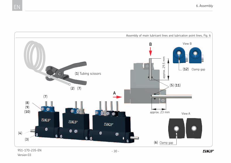
Connecting the lubrication point lines
• Use tubing scissors (1) to cut the lu-
brication point lines (7) to the required
lengths, ensure there are no burrs
• Loosen the hexagon socket screw (8)
(WAF 3) of the clipped connection (9) on
the metering piece (10).
• Insert lubrication point lines (7) into the
clipped connection to the stop position
(9) (approx. 29.5 mm) overcoming the
resistance of the inserted O-ring (11)
• Bring the lubrication point lines into
mounting position
• Tighten the hexagon socket screw (8)
until the clamp gap (12) on the clipped
connection (9) is closed (this is the case
at approx. 1.5 Nm)
• Repeat the assembly procedure on the
other metering pieces
Connecting the main lubricant lines
• Use tubing scissors (1) to cut the main
lubricant lines (2) to the required lengths,
ensure there are no burrs
• Loosen the hexagon socket screw (3)
(WAF 3) of the clipped connection (4) on
the main line connection on the left
• Insert the main lubricant lines (2) into the
clipped connection (4) to the stop posi-
tion (approx. 23 mm), overcoming the
resistance of the inserted O-ring (5)
• Bring the main lubricant lines into
mounting position
• Tighten the hexagon socket screw (3)
until the clamp gap (6) on the clipped
connection (4) is closed (this is the case
at approx. 1.5 Nm)
• If necessary, repeat the assembly proce-
dure on the main line connection on the
right
EN 6. Assembly
- 30 -951-170-235-EN
Version 03
Clamp gap
View A
Assembly of main lubricant lines and lubrication point lines, Fig. 6
(6)
(7)
A
B
(5) (11)
(1) Tubing scissors
(2)
(3)
(4)
approx. 23 mm
(7)
(8)(9)(10)
appr
ox. 29.5
mm
View B
Clamp gap (12)

6
EN6. Assembly
- 31 - 951-170-235-EN
Version 03
6.7 Venting the lubricant distributors
-See Figure 7 and Fig. 8
Requirement
○ Lubricant pump and components of the
single-line centralized lubrication system
have been mounted correctly
○ Lubricant pump is already filled with lu-
bricant and subsequently vented
○ Main lubricant lines and lubrication point
lines are already filled with lubricant
6.7.1 Venting procedure for main lubricant lines
See Figures 7 and 8
The venting procedure for the main lubri-
cant lines is carried out on the main lubri-
cant lines on the lubricant distributor (1)
farthest from the lubrication pump
• Switch on the lubricant pump (2)
• Loosen the hexagon socket screw of the
clipped connection (4) on the distributor
outlet (3) (WAF 3)
• Remove the plug (5)
• Allow the lubricant pump (2) to run until
bubble-free lubricant discharges at the
clipped connection (4).
• Insert the plug (5) into the clipped con-
nection (4) to the stop position, overcom-
ing the resistance of the inserted O-ring
• Tighten the hexagon socket screw (4)
until the clamp gap on the clipped con-
nection is closed (this is the case at ap-
prox. 1.5 Nm)
Repeat if necessary in case of branches.
(2)
(5)
(3 /4)
Single-line system with lubricant distributors
of product series 310, Fig. 7
(1)
EN 6. Assembly
- 32 -951-170-235-EN
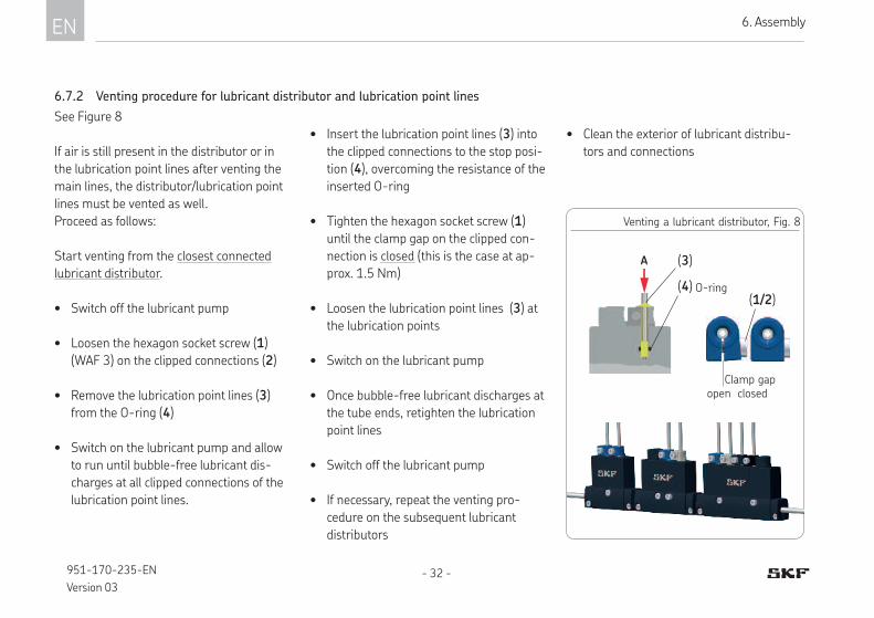
Version 03
• Insert the lubrication point lines (3) into
the clipped connections to the stop posi-
tion (4), overcoming the resistance of the
inserted O-ring
• Tighten the hexagon socket screw (1)
until the clamp gap on the clipped con-
nection is closed (this is the case at ap-
prox. 1.5 Nm)
• Loosen the lubrication point lines (3) at
the lubrication points
• Switch on the lubricant pump
• Once bubble-free lubricant discharges at
the tube ends, retighten the lubrication
point lines
• Switch off the lubricant pump
• If necessary, repeat the venting pro-
cedure on the subsequent lubricant
distributors
Venting a lubricant distributor, Fig. 8
(3)
(4)
See Figure 8
If air is still present in the distributor or in
the lubrication point lines after venting the
main lines, the distributor/lubrication point
lines must be vented as well.
Proceed as follows:
Start venting from the closest connected
lubricant distributor.
• Switch off the lubricant pump
• Loosen the hexagon socket screw (1)
(WAF 3) on the clipped connections (2)
• Remove the lubrication point lines (3)
from the O-ring (4)
• Switch on the lubricant pump and allow
to run until bubble-free lubricant dis-
charges at all clipped connections of the
lubrication point lines.
open closed
O-ring
A
(1/2)
Clamp gap
6.7.2 Venting procedure for lubricant distributor and lubrication point lines
• Clean the exterior of lubricant distribu-
tors and connections

7
EN7. Initial commissioning
6
- 33 - 951-170-235-EN
Version 03
7. Initial commissioning
Checklist for commissioning
7.1 Inspections before initial commissioningYES NO
Mechanical connection established correctly
The performance data for the aforementioned connections matches the specifications in “Technical data”
All components such as lubrication point lines are correctly mounted
No apparent damage or contamination
Any dismantled protective and monitoring equipment is fully reinstalled and functional
7.2 Inspections during initial commissioning
No undesired discharge of lubricant at connections (leaks)
Lubricant is fed without bubbles
The bearings and friction points requiring lubrication receive the planned amount of lubricant
To ensure safety and functionality, the person specified by the operator is required to perform the following inspections. Any detected defi-
ciencies must be resolved immediately. The correction of deficiencies must be done exclusively by a specialist competent and authorized to
do so.

EN 8. Operation / 9. Cleaning
- 34 -951-170-235-EN
Version 03
8. Operation
SKF products operate automatically.
The activities required during normal opera-
tion are limited primarily to cleaning of the
exterior of the product if contaminated.
NOTE!
The lubricant metering device of
product series 310 is made almost
entirely of functional high-per-
formance plastics, some of whose
semi-crystalline basic structure
causes them to react to water-
based media.
To always ensure that the lubricant
metering device functions properly,
it is recommended that you avoid
constant and excessive contact with
water-based media (e.g., cooling
lubricant). Further, contact with
acids or oxidizing chemicals must
be excluded.
9. Cleaning
9.1 Cleaning agents
Only cleaning agents compatible with the
materials can be used for cleaning (see
Chapter 2.3 for materials).
Always completely remove residue
of the cleaning agent on the prod-
uct and rinse with clear water. This
prevents the formation of alkaline
deposits.
9.2 Exterior cleaning
• Mark and secure wet areas.
• Unauthorized persons must be kept
away.
• Thoroughly clean all external surfaces
with a moist cloth.
9.3 Interior cleaning
Cleaning of the interior of the distributor/
metering pieces is prohibited.
During cleaning, pay attention to the
following:
¹ Cleaning, required personal protective
gear, cleaning agents, and equipment are
in accordance with the current operating
rules of the operator.
10
EN10. Maintenance
8
9
- 35 - 951-170-235-EN
Version 03
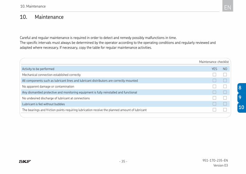
10. Maintenance
Careful and regular maintenance is required in order to detect and remedy possibly malfunctions in time.
The specific intervals must always be determined by the operator according to the operating conditions and regularly reviewed and
adapted where necessary. If necessary, copy the table for regular maintenance activities.
Maintenance checklist
Activity to be performed YES NO
Mechanical connection established correctly
All components such as lubricant lines and lubricant distributors are correctly mounted
No apparent damage or contamination
Any dismantled protective and monitoring equipment is fully reinstalled and functional
No undesired discharge of lubricant at connections
Lubricant is fed without bubbles
The bearings and friction points requiring lubrication receive the planned amount of lubricant

EN 11. Malfunctions / 12. Repairs
- 36 -951-170-235-EN
Version 03
11. Malfunctions, causes, and remedies 12. Repairs
The 310 seires lubricant distributor is not
designed to be repaired.
NOTE! The main lines and lubrication lines are each secured to the lu-bricant metering device of prod-uct series 310 using a clipped connection. If the main line and/or the lubricant lines are to be replaced, SKF recommends also replacing the affected lubricant metering device at the same time.
If replacement is not performed,
the metering device’s function
may be impaired under certain
circumstances.
Malfunctions table
Malfunction: No lubricant at the lubrication point
Possible cause Remedy
Insufficient system pressure at
main line connection
Check system pressure at the main line connection, increase system pressure if necessary (min. 12 bar to max. 38 bar)
Distributor jam/
insufficient pressure relief
Trigger interim lubrication while loosening the clipped con-nection on the lubrication point line of the affected meter-ing piece The distributor is working correctly if lubricant can be clearly seen discharging.
Contamination
hardened grease
Distributor jam:-Switch off lubricant pump, relieve pressure, replace distributor
Lubrication point lines:- Check lubrication point lines for clogging, pinching, kink-ing, hardened grease, or clogging of the lubrication point; remedy the cause..
Main lubricant lines:- Flush the main line; to do so, remove the plug on the last lubricant distributor switch on the pump, and replace the plug only once dirt-free lubricant discharges consistently.
13
EN13. Shutdown, disposal
11
12
- 37 - 951-170-235-EN
Version 03
13. Shutdown, disposal
13.1 Temporary shutdown
Temporary shutdown is performed by:
¹ Switching off the main machine
13.3 Disposal
Waste should be avoided or minimized to
the extent possible. The disposal of prod-
ucts contaminated with lubricant must be
performed by a recognized waste disposal
company in compliance with environmental
protection requirements and waste disposal
regulations as well as the requirements of
local authorities.
The producer of waste is respon-
sible for its specific classification,
as the European Waste Catalog
provides for different disposal
keys for waste that is the same
but of different origin.
Plastic or metallic parts that
have been cleaned of lubricant
can be disposed of as industrial
waste.
13.2 Permanent shutdown, disassembly
Permanent shutdown and disassembly of
the product must be planned properly by the
operator and conducted in compliance with
all applicable requirements.

EN 14. Accessories
- 38 -951-170-235-EN
Version 03
14. Accessories
Fig. 9
14.1 Plugs/clamp connections
Item Designation Units Item number
1 Plug 1 898-210-001
2 M4 clamping screw 1 DIN 912-M4x10-8.8
3 Nut for M4 clamping screw 1 DIN 934-M4-5
1
14.2 Plastic tubing
Designation Tube Ø Units Item number
Plastic tubing (unplasticized)
4 mm
1)
WVN715-R04x0.85
6 mm
WVN715-R06x1
WVN715-R06x1.25
WVN715-R06x1.5
Plastic tubing, flexible (plasticized)4 mm WVN716-R04x0.85
2)6 mm WVN716-R06x1.25
Special scissors for plastic tubing (tubing scissors) 226-12508-5
Note!
You can ind additional technical data in the brochures: Brochure No.:
Lubricant Distributors for SKF MonoFlex Systems 1-5001-EN
Fittings and Accessories 1-0103-EN
Transport of Lubricants in Centralized Lubrication Systems 1-9201-EN
1) Add the desired length, e.g. 30 meters, to
the order number.
Order example:
WVN715-R04x0.85 x30 meters
2) When using flexible plastic tubing, ob-
serve its technical operating conditions ac-
cording to SKF brochure “Fittings and acces-
sories,” brochure No. 1-0103-EN.
2/3
2/3

Notes

951-170-235-EN
June 2018Version 03
SKF Lubrication Systems Germany GmbH Motzener Straße 35/37 · 12277 Berlin · Germany
PO Box 970444 · 12704 Berlin · Germany
Tel. +49 (0)30 72002-0
Fax +49 (0)30 72002-111
www.skf.com/lubrication
Seals
Mechatronics Services
Lubrication Systems
Bearingsand Bearing
Units
The Power of Knowledge Engineering
Over the course of more than a century, SKF has specialized in five fields of competence and
acquired a wide range of application expertise. We utilize this experience to provide innovative
solutions to OEMs and other manufacturers in practically all industrial sectors worldwide.
Our five fields of competence are: Bearings and bearing units, seals, mechatronics (combining
mechanical and electronic components to improve the performance of classic systems), and exten-
sive services from 3-D computer stimulations and modern condition monitoring systems for high
reliability to system management SKF is a leading global company and guarantees its customers
uniform quality standards and global product availability.


