
Low‐Swirl Injectors for High Hydrogen Fuel Gas Turbines
Robert K. Cheng
Environmental Energy Technologies DivisionLawrence Berkeley National Laboratory
Berkeley, CA 94720
Research supported by NETL ‐ Fossil Energy, US Dept. of Energy
Presentation at UTSR Workshop - Oct. 26, 2011
1
Participants and Collaboratorsp
LBNL – Environmental Energy Technology Div.Robert Cheng, David Littlejohn, Peter Therkelsen, Ken Smith, & Sy Ali
United Tech. Research Center – Pratt & Whitney Power SystemsDustin Davis, Justin Locke, Catalin Fotache & Richard Tuthill
Florida Turbine TechnologiesRussell Jones & Joe Brostmeyer
LBNL – Computational Research Div.John Bell & Marc Day
Siemens Energy Inc.Scott Martin & Enrique Portillo Bilbao
University of California, IrvineVince, McDonnell, David Beerer & Adrian A. Narvaez
2
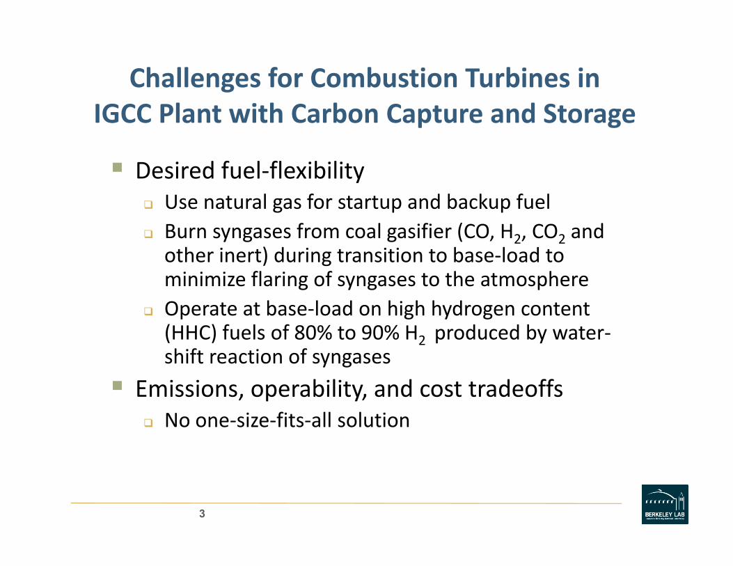
Challenges for Combustion Turbines inIGCC Pl i h C b C d SIGCC Plant with Carbon Capture and Storage
Desired fuel‐flexibilityDesired fuel flexibilityUse natural gas for startup and backup fuelBurn syngases from coal gasifier (CO, H2, CO2 and h ) d b l dother inert) during transition to base‐load to
minimize flaring of syngases to the atmosphereOperate at base‐load on high hydrogen content p g y g(HHC) fuels of 80% to 90% H2 produced by water‐shift reaction of syngases
Emissions operability and cost tradeoffsEmissions, operability, and cost tradeoffsNo one‐size‐fits‐all solution
3
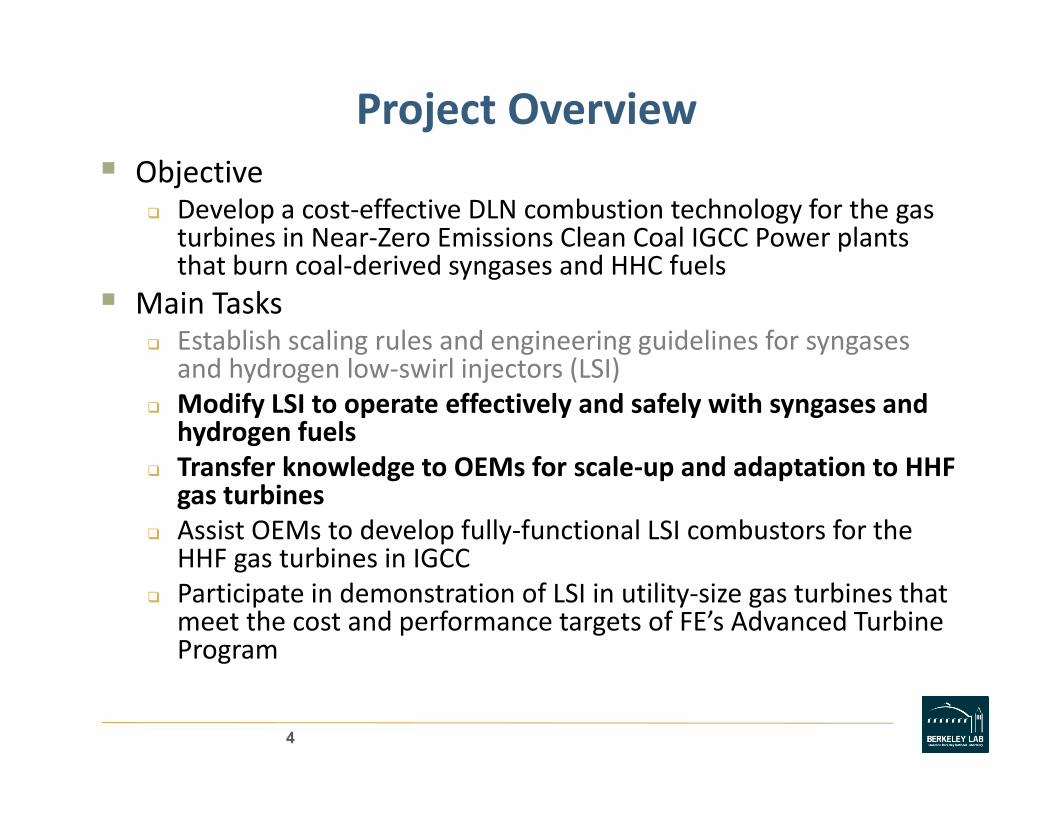
Project OverviewObjective
Develop a cost‐effective DLN combustion technology for the gas turbines in Near‐Zero Emissions Clean Coal IGCC Power plants that burn coal‐derived syngases and HHC fuels
Main TasksEstablish scaling rules and engineering guidelines for syngasesand hydrogen low‐swirl injectors (LSI)Modify LSI to operate effectively and safely with syngases and hydrogen fuelsT f k l d OEM f l d d i HHFTransfer knowledge to OEMs for scale‐up and adaptation to HHF gas turbinesAssist OEMs to develop fully‐functional LSI combustors for the HHF gas turbines in IGCCHHF gas turbines in IGCCParticipate in demonstration of LSI in utility‐size gas turbines that meet the cost and performance targets of FE’s Advanced Turbine Programg
4

Fuel‐Flexible Low‐Swirl InjectorDevelopment Statusp
Demonstrated fuel‐flexible LSI operation at STPModified nozzle exit profile to mitigating
b ti d iLSI swirlerfor CFD studies
combustion dynamicsAddressed issues specific to H2 flame behaviorbehaviorDeveloped and tested a sub‐scale fuel‐flexible LSI at gas turbine relevant gconditions
5

Conceptual Design Study of LSI for 3 fuel Gas TurbineLSI for 3‐fuel Gas Turbine
Subcontract to United Technology Research Center and Pratt & Whitney Power Systems (UTRC/PWPS)
Gas turbine manufacturer participation to address T h l R di L l (TRL)Technology Readiness Level (TRL)
ObjectivesConceptual architecture of a 3‐fuel LSI system and operation modelsDesign and fabricate a fully functional sub‐scale LSI for natural gas and hydrogen‐rich fuel blend V if l d HHF i li i biVerify natural gas and HHF operation at realistic gas turbine conditions
6
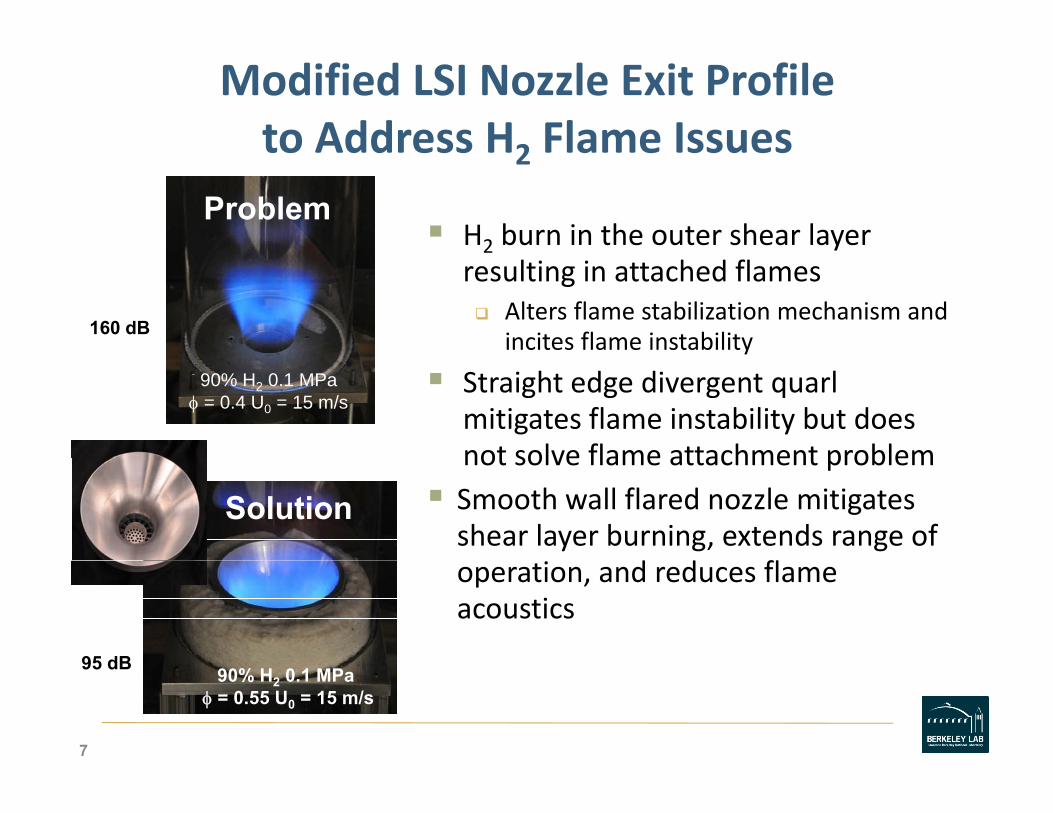
Modified LSI Nozzle Exit Profile to Address H2 Flame Issuesto Address H2 Flame Issues
H2 burn in the outer shear layer Problem
resulting in attached flamesAlters flame stabilization mechanism and incites flame instability
160 dB
Straight edge divergent quarlmitigates flame instability but does not solve flame attachment problem
90% H2 0.1 MPaφ = 0.4 U0 = 15 m/s
not solve flame attachment problemSmooth wall flared nozzle mitigates shear layer burning, extends range of
d d fl
Solution
operation, and reduces flame acoustics
95 dB 90% H2 0.1 MPaφ = 0.55 U0 = 15 m/s
95 dB
7

Verification of Flared Nozzle Operability at Simulated Gas Turbine Conditionsat Simulated Gas Turbine Conditions
LSI with flared nozzle fabricated for U.C. Irvine’s down fired high pressure facility
3 8 cm I D with benchmark3.8 cm I.D. with benchmark swirler design (16 thickened vanes, 37o blade angle) Upstream fuel spoke injectors
Tested with natural gas and HHC fuel of 90% H2 10% CH4
20 < U0 < 30 m/s, 3 < P > 6 Mpa 290 < T < 600KMpa, 290 < T < 600KNOx, flashback and blowoffinvestigatedIGTI paper planned
8

Despite Differences in Swirler Configuration, Premixer and Nozzle Exit Profile NO Emissions atPremixer, and Nozzle Exit Profile, NOx Emissions at
UCI Comparable to Previous NETL Results
• H2 flames have slightly higher Noxat lower Tat lower Tad• Vertical error bars
show uncertainty of Horiba PG250
• Horizontal error bars show uncertainty in equivalence ratio (+/‐0 02)0.02)
9

Sub‐scale LSI Prototype DevelopmentCl BN /UTC
Rapid Screening at LBNL Metal Hardware
•Fuel circuits
• Close LBNL/UTC collaboration critical
Conceptual
•UTR proprietary mixer•Flares nozzle•Swirler
pDesign
Refined Concept
LBNLApproval
CFD Design Tools
Rapid Prototype Resin Solid Models
10

Results from Sub‐Scale 3‐Fuel LSI PrototypeResults from Sub Scale 3 Fuel LSI Prototype
Tested with natural gas and diluted hydrogen NG/H2/N2 H2/N2
at gas turbine relevant conditions
LSI demonstrated stable operation (ease of light‐off, loading, and very low dynamics) at all test points
All NOx emissions well below 10 ppmLow single digit NOx from natural gas matchesLow single digit NOx from natural gas matches Leonard and Seigmaier curve
11

Conclusions of UTRC StudiesConclusions of UTRC Studies
Verified multi‐fuel LSI concept for gas turbineVerified multi fuel LSI concept for gas turbine operation
Found new operating mode for LSIFound new operating mode for LSI
Need some improvement for H2 operation
Design can be further simplified for scale‐up
12

Florida Turbine Technologies DevelopingHigh Efficiency MW size Gas Turbine with LSIHigh Efficiency MW‐size Gas Turbine with LSI
ObjectiveDesign a combustor around the LSI to enable high efficiency (approaching 60% in a combined cycle system) with ultra‐low emissions
RequirementsSingle digit NOxL b t lLow combustor pressure loss
StatusInitial system design completey g pDetailed LSI combustor layout completeLaboratory evaluation of LSI complete
13
Basic Research Supportingpp gTechnology Development
(LSI self‐excited flame instabilities (collaboration with Siemens and UTRC)
Obtain basic understanding of combustion oscillation processes in gas turbinesprocesses in gas turbines
Turbulent displacement flame speed at gas turbine relevant conditions (collaboration with UC Irvine)
Investigate basic properties of premixed turbulent flames g p p prelevant to predicting flashback
Symbiotic experimental/numerical studies of thermal/diffusive effects in turbulent lean HHC flames (collaboration with LBNL Computation Research Division)(collaboration with LBNL Computation Research Division)
Study basic turbulent flame structures to help develop model
14
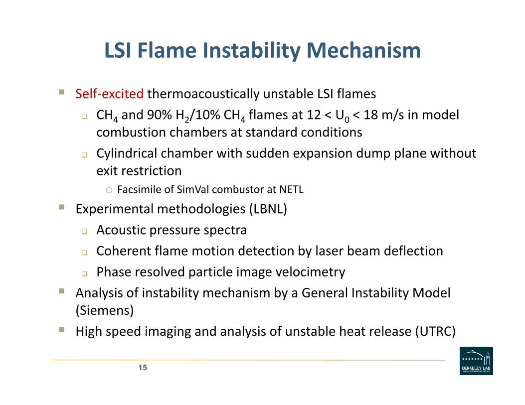
LSI Flame Instability Mechanism
Self‐excited thermoacoustically unstable LSI flames
CH4 and 90% H2/10% CH4 flames at 12 < U0 < 18 m/s in model combustion chambers at standard conditions
Cylindrical chamber with sudden expansion dump plane without exit restriction
o Facsimile of SimVal combustor at NETL
Experimental methodologies (LBNL)
Acoustic pressure spectraAcoustic pressure spectra
Coherent flame motion detection by laser beam deflection
Phase resolved particle image velocimetry
Analysis of instability mechanism by a General Instability Model (Siemens)
High speed imaging and analysis of unstable heat release (UTRC)High speed imaging and analysis of unstable heat release (UTRC)
15

High Swirl vs. Low SwirlHigh Swirl vs. Low Swirl
High swirl Low swirl injector uses a central recirculatio
injector stabilizes flames at the centralrecirculatio
n zone (CRZ) to stabilize fl
the central divergence zone (CDZ)
flames.
L S i lHi h S i l Low SwirlHigh Swirl
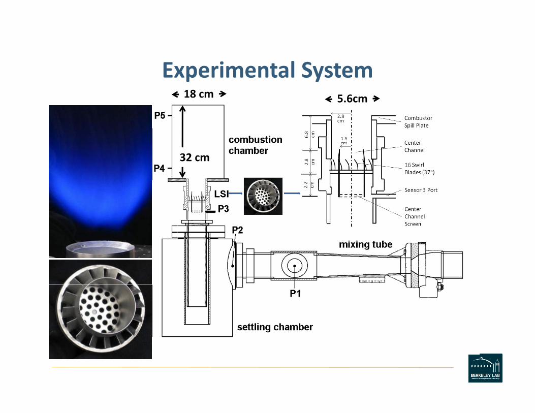
Experimental SystemExperimental System18 cm 5.6cm
32 cm
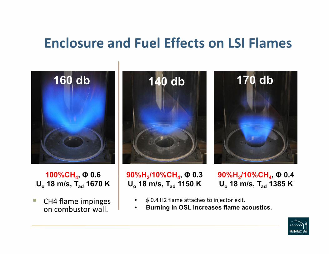
Enclosure and Fuel Effects on LSI FlamesEnclosure and Fuel Effects on LSI Flames
170 db160 db 140 db 170 db160 db 140 db
90%H /10%CH Φ 0 4100%CH Φ 0 6 90%H /10%CH Φ 0 3 90%H2/10%CH4, Φ 0.4Uo 18 m/s, Tad 1385 K
100%CH4, Φ 0.6Uo 18 m/s, Tad 1670 K
CH4 flame impinges b t ll
90%H2/10%CH4, Φ 0.3Uo 18 m/s, Tad 1150 K
• φ 0.4 H2 flame attaches to injector exit.• Burning in OSL increases flame acousticson combustor wall. • Burning in OSL increases flame acoustics.
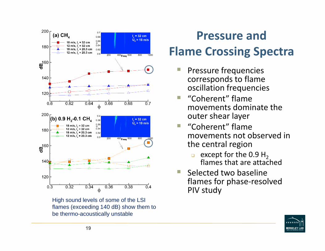
Pressure and Flame Crossing Spectra
Pressure frequencies corresponds to flamecorresponds to flame oscillation frequencies“Coherent” flame movements dominate themovements dominate the outer shear layer “Coherent” flame movements not observed in h l ithe central region
except for the 0.9 H2flames that are attached
Selected two baselineSelected two baseline flames for phase‐resolved PIV study
High sound levels of some of the LSI fl ( di 140 dB) h hflames (exceeding 140 dB) show them to be thermo-acoustically unstable
19
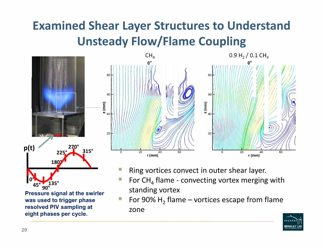
Examined Shear Layer Structures to Understand Unsteady Flow/Flame Couplingy / p g
Ring vortices convect in outer shear layer180°
315°270°
225°p(t)
Ring vortices convect in outer shear layer.For CH4 flame ‐ convecting vortex merging with standing vortexFor 90% H2 flame – vortices escape from flame
0°45° 135°
90°Pressure signal at the swirlerwas used to trigger phase 2 p
zone
20
gg presolved PIV sampling at eight phases per cycle.
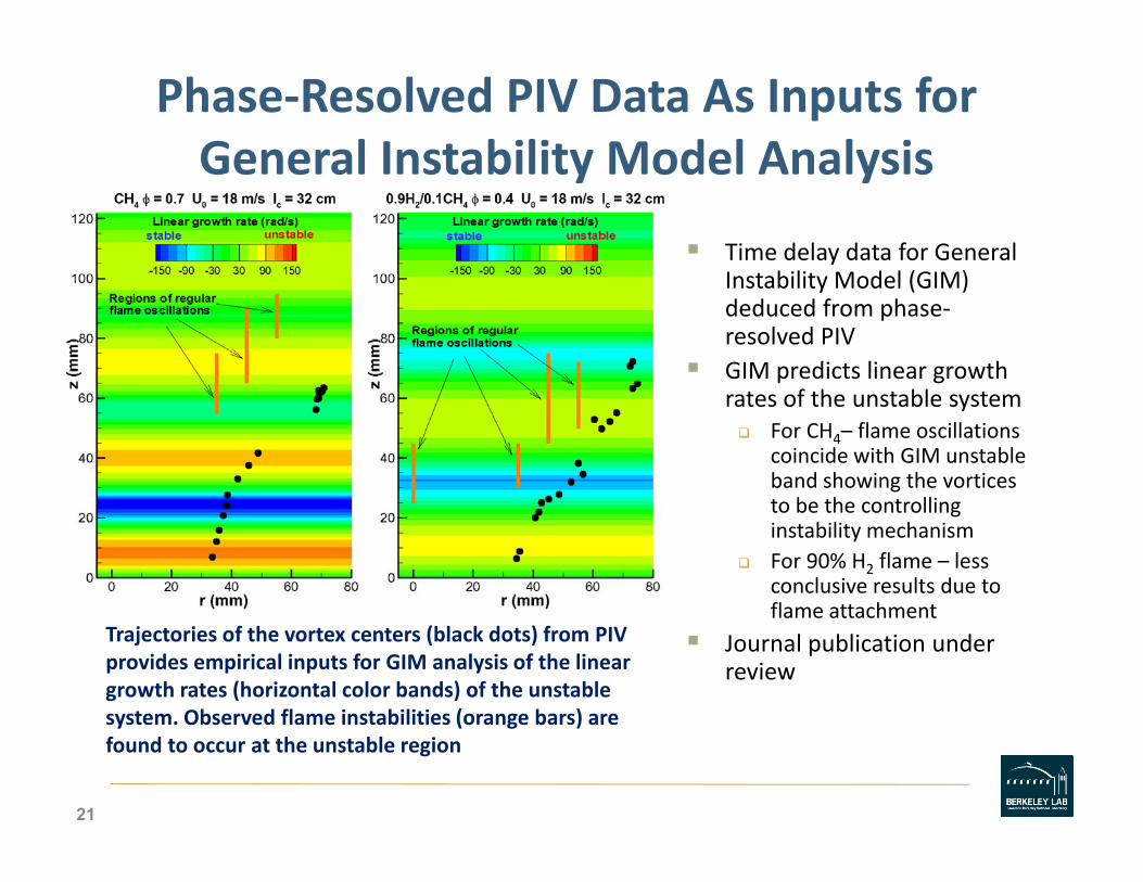
Phase‐Resolved PIV Data As Inputs for General Instability Model AnalysisGeneral Instability Model Analysis
Time delay data for General I t bilit M d l (GIM)Instability Model (GIM) deduced from phase‐resolved PIV GIM predicts linear growth rates of the unstable system
For CH4– flame oscillations coincide with GIM unstable band showing the vortices to be the controlling instability mechanism For 90% H2 flame – less conclusive results due to flame attachmentflame attachment
Journal publication under review
Trajectories of the vortex centers (black dots) from PIV provides empirical inputs for GIM analysis of the linear growth rates (horizontal color bands) of the unstable system Observed flame instabilities (orange bars) aresystem. Observed flame instabilities (orange bars) are found to occur at the unstable region
21

High Speed Imaging of Unstable Heat Releasesof CH and 0 9 H /0 1CH Flamesof CH4 and 0.9 H2/0.1CH4 Flames
Spectral behavior captured by hi h d i i (4K H ) fhigh‐speed imaging (4K Hz) of OH chemiluminescence
Obtained data for a series of flamesflames
Phase dependent heat release profiles deduced from Proper Orthogonal DecompositionOrthogonal Decomposition (POD) analyze
Comparison with phase‐resolved PIV examinesresolved PIV examines coupling of unsteady velocity field with Rayleigh indices
UTC Proprietary
22

Phase Resolved PIV and OH Contours Show Correlation Between Flame and Vortical Structures
U contours vs θOHA B A CB
Ur contours vs θOH
A
C
FEDD
23
D E
F
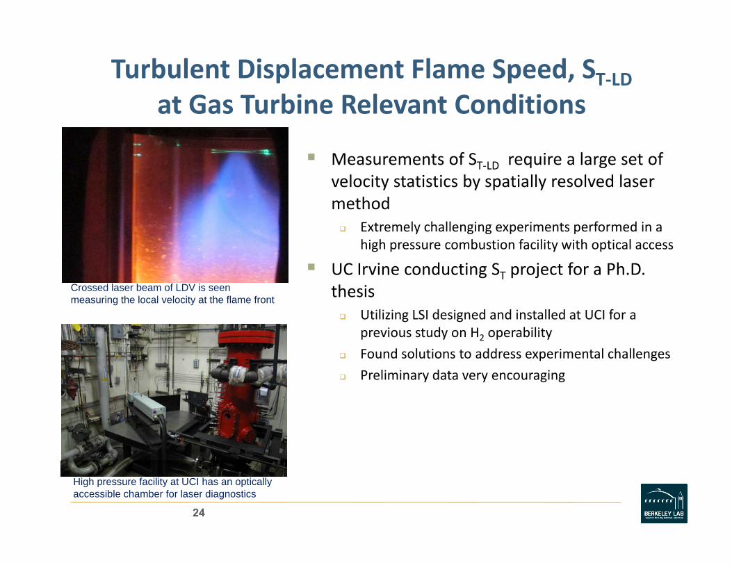
Turbulent Displacement Flame Speed, ST‐LDat Gas Turbine Relevant Conditionsat Gas Turbine Relevant Conditions
Measurements of ST‐LD require a large set of l i i i b i ll l d lvelocity statistics by spatially resolved laser
methodExtremely challenging experiments performed in a high pressure combustion facility with optical accesshigh pressure combustion facility with optical access
UC Irvine conducting ST project for a Ph.D. thesis
Utilizing LSI designed and installed at UCI for a
Crossed laser beam of LDV is seen measuring the local velocity at the flame front
Utilizing LSI designed and installed at UCI for a previous study on H2 operability
Found solutions to address experimental challenges
Preliminary data very encouraging
High pressure facility at UCI has an optically accessible chamber for laser diagnostics
24

Symbiotic Experimental/Numerical Studies toInvestigate Lean Premixed Turbulent H2 FlamesInvestigate Lean Premixed Turbulent H2 Flames
Collaboration with LBNL Center for Computational Science and Engineering ( ) l h(CCSE) at Computational Research DivisionNumerical Approach
Via CCSE’s Low Mach Number Combustion (LMC) codeo Has uniquely capable incorporating experimentally relevant domain (25 cm)3 with detailed chemical kinetics, transport & efficient adaptive numerical methods
o Requires DOE‐BES “INCITE”‐level resources on ORNL’s JaguarPFo Requires DOE‐BES INCITE ‐level resources on ORNLs JaguarPFsupercomuter
ChallengesNeed to establish tremendous confidence in simulationsNeed to establish tremendous confidence in simulationsLarge amount of simulated data requires new diagnostics and experimentalists’ perspective to analyze
25

Extracting Insights from LMC Results
New diagnostics are being developed for g g pthe high dimensionality, large simulation datasets to support the development of turbulent flame modelsRecent diagnostics:Recent diagnostics:
“Flame‐surface” (isotherm) statisticsJoint correlations (flame curvature, strain)Flame‐normal analysis of dynamics in flame frameLagrangian tracer statistics – flame dynamics in the frame of the fluiddynamics in the frame of the fluid
Paper reporting new diagnostics on CH4flames to appear in Comb. & FlameA new Lagrangian tracer method has been developed for
analyzing LMC simulations of the LSB flames. Properties along the tracer paths through the flame (e.g. temperature as show above) are better suited for elucidating H2 flame behavior than the conventional iso‐surface approach
26

H2 Turbulent Flame Structures Do Not Conform toClassic Wrinkled Flamelet AssumptionClassic Wrinkled Flamelet Assumption
LMC simulation domain25 x 25 x 25 cm
LMC FOV1 LMC FOV2
Simulated and measured instantaneous OH concentrations of a PLIF FOV1 PLIF FOV2
LMC simulation of a LSB H2
H2 flames have OH gaps due to thermal/diffusive instability effects
H2/air flame at Uo = 15 m/s, φ = 0.37 show gaps in the concave regionsLMC simulation of a LSB H2flame show hot‐spots in the convex regions
Combustion models for non‐uniform “discontinuous” flame front are not available
Largrangian tracer analysis on simulated results is developed specifically to define proper modeling treatments for H2 flames
27

Next Step for LMC: Pollutant Formation in Lean Premixed Hydrogen Flamesin Lean Premixed Hydrogen Flames
NO formation in cellular flamesNOx formation in cellular flames may explain 1 ppm NOx ‘floor’ of H2 flames
Enhanced burning, local enrichment results from high H2 diffusivity
Simulation quantifies the formation of if NO flnon‐uniform NO over flame
Other fundamental issues of H2flames:
Rethink the “flame front” concept
Applicability of 1D steady flame model
Limits of experimental validationIsovolume showing X(NO) with fuel boundary (red) and vorticity from
i l ( )
28
pswirl (grey)

Parametric Study on LSI Swirler Configuration A D i G id li f G T bito Augment Design Guidelines for Gas Turbines
Comparing performances R = 0 8 R = 0 67 R = 0 52
and flowfields of ten LSI swirlers
320 < α < 420
R = 0.8 R = 0.67 R = 0.52
42o
0.52 < R < 0.8Thick & thin curved vanes
Initial findings37o
Initial findings LBO insensitive to swirlergeometryswirl number directly=
32o
swirl number directly proportional to vane angleΔP/P drops with reducing R
α=
29

Planned Activities:Planned Activities:
Augment Design Guidelines for LSIug e t es g Gu de es o SLaboratory experiments on 9 variants of basic vane LSI swirler
Characterize LSI Flame InstabilitiesContinue collaborations with Siemens and UTRC
Local Displacement Turbulent Flame SpeedComplimentary experiments at UCI and LBNL
I i L l S f CH /H T b lInvestigate Local Structures of CH4/H2 Turbulent Flames
Flowpath analysis of simulated LSB flamesFlowpath analysis of simulated LSB flames
30


